WO2021230197A1 - 点火器組立体及びそれを備えるガス発生器 - Google Patents
点火器組立体及びそれを備えるガス発生器 Download PDFInfo
- Publication number
- WO2021230197A1 WO2021230197A1 PCT/JP2021/017691 JP2021017691W WO2021230197A1 WO 2021230197 A1 WO2021230197 A1 WO 2021230197A1 JP 2021017691 W JP2021017691 W JP 2021017691W WO 2021230197 A1 WO2021230197 A1 WO 2021230197A1
- Authority
- WO
- WIPO (PCT)
- Prior art keywords
- igniter
- peripheral wall
- support portion
- resin molded
- molded body
- Prior art date
Links
Images


Classifications
-
- B—PERFORMING OPERATIONS; TRANSPORTING
- B60—VEHICLES IN GENERAL
- B60R—VEHICLES, VEHICLE FITTINGS, OR VEHICLE PARTS, NOT OTHERWISE PROVIDED FOR
- B60R21/00—Arrangements or fittings on vehicles for protecting or preventing injuries to occupants or pedestrians in case of accidents or other traffic risks
- B60R21/02—Occupant safety arrangements or fittings, e.g. crash pads
- B60R21/16—Inflatable occupant restraints or confinements designed to inflate upon impact or impending impact, e.g. air bags
- B60R21/26—Inflatable occupant restraints or confinements designed to inflate upon impact or impending impact, e.g. air bags characterised by the inflation fluid source or means to control inflation fluid flow
- B60R21/264—Inflatable occupant restraints or confinements designed to inflate upon impact or impending impact, e.g. air bags characterised by the inflation fluid source or means to control inflation fluid flow using instantaneous generation of gas, e.g. pyrotechnic
- B60R21/2644—Inflatable occupant restraints or confinements designed to inflate upon impact or impending impact, e.g. air bags characterised by the inflation fluid source or means to control inflation fluid flow using instantaneous generation of gas, e.g. pyrotechnic using only solid reacting substances, e.g. pellets, powder
-
- B—PERFORMING OPERATIONS; TRANSPORTING
- B60—VEHICLES IN GENERAL
- B60R—VEHICLES, VEHICLE FITTINGS, OR VEHICLE PARTS, NOT OTHERWISE PROVIDED FOR
- B60R21/00—Arrangements or fittings on vehicles for protecting or preventing injuries to occupants or pedestrians in case of accidents or other traffic risks
- B60R21/02—Occupant safety arrangements or fittings, e.g. crash pads
- B60R21/16—Inflatable occupant restraints or confinements designed to inflate upon impact or impending impact, e.g. air bags
- B60R21/26—Inflatable occupant restraints or confinements designed to inflate upon impact or impending impact, e.g. air bags characterised by the inflation fluid source or means to control inflation fluid flow
- B60R2021/26029—Ignitors
Definitions
- the present disclosure relates to an igniter assembly in which an electrically ignitable igniter body is attached to an igniter collar and a gas generator including the igniter assembly.
- Patent Document 1 discloses a metal fixing member and a gas generator in which an igniter is fixed to a lower shell by a resin molding portion.
- the present disclosure aims to provide a technique for improving the withstand voltage performance of the igniter assembly.
- a second support portion is provided on the peripheral wall portion of the igniter collar at a position farther from the ignition portion than the first support portion and the first support portion. ..
- an igniter filled with an igniter an igniter body having a conductive part extending from the igniter, and a tubular peripheral wall that at least surrounds the conductive part of the igniter body.
- An igniter assembly comprising an igniter collar having a portion and a resin molded body interposed between the igniter body and the igniter collar to integrate the igniter body and the igniter collar.
- the igniter collar is provided on the inner peripheral portion of the peripheral wall portion, and is formed in a convex shape toward the radial inward side of the peripheral wall portion so as to be embedded in the resin molded body.
- the peripheral wall is provided at a position away from the ignition portion from the first support portion in the direction along the central axis of the peripheral wall portion so as to be buried in the resin molded body.
- a second support portion formed in a convex shape toward the radial inner side of the portion, or concave toward the radial outer side of the peripheral wall portion so that the resin molded body is filled inside.
- the minimum dimension of the first support portion in the direction along the central axis is equal to or larger than the minimum dimension of the second support portion in the direction along the central axis.
- the igniter assembly In the igniter assembly, cracks are likely to occur in the part where the thickness of the resin molded body is the thinnest due to the impact when the igniter body operates. Even if a crack occurs in the resin molded body, the igniter assembly supports the resin molded body on the ignition part side from the crack by the first support portion, and the resin molded body on the tip side of the conductive part from the crack. It is supported by the second support part. As a result, in the igniter assembly of the present disclosure, even if the resin molded body is cracked and separated, a part of the resin molded body will protrude to the outside of the igniter assembly. Therefore, the withstand voltage performance can be improved.
- the connector connection space for connecting the connector for transmitting the operation signal of the igniter body to the conductive portion is larger than the first support portion in the direction along the central axis.
- the second support portion is formed on the tip end side of the conductive portion, and the second support portion is convex inward in the radial direction of the peripheral wall portion so as to be embedded in the resin molded body and faces the connector connection space. It may be formed at a position where the connector is formed.
- the connector connection space can easily secure a predetermined dimension in the radial direction of the peripheral wall portion of the igniter collar and the direction along the central axis.
- the connector connection space makes it easy to secure a space for forming a second support portion that is convex inward in the radial direction of the peripheral wall portion of the igniter collar.
- a plurality of the second support portions may be discontinuously formed along the circumferential direction of the peripheral wall portion.
- a plurality of second support portions are formed discontinuously along the circumferential direction of the peripheral wall portion, so that the resin molded body 4 rotates with respect to the igniter collar after the resin molded body is cured of the resin. Can be prevented from doing so.
- the present disclosure is a gas generator, which may include an outer shell container having a gas discharge port and the above-mentioned igniter assembly arranged inside the outer shell container.
- the igniter assembly of the present disclosure can be used for a gas generator.
- the outer shell container is formed by combining the first shell and the second shell, and a part of either the first shell or the second shell has the igniter collar.
- the igniter assembly may be fixed to either the first shell or the second shell, which is partly the igniter collar, by the resin molded body. In this way, a part of the outer shell container may be configured as an igniter collar.
- the withstand voltage performance of the igniter assembly can be improved.
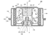
- FIG. 1 is a diagram showing a schematic configuration of a gas generator including the igniter assembly according to the first embodiment.
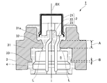
- FIG. 2 is a diagram showing a schematic configuration of the igniter assembly according to the first embodiment.
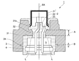
- FIG. 3 is a diagram showing a schematic configuration of the igniter assembly according to the second embodiment.
- FIG. 4 is a diagram showing a schematic configuration of the igniter assembly according to the first modification of the second embodiment.
- FIG. 5 is a diagram showing a schematic configuration of the igniter assembly according to the second modification of the second embodiment.
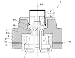
- FIG. 6 is a diagram showing a schematic configuration of a gas generator according to the third embodiment.
- FIG. 1 is an axial sectional view of an airbag gas generator (hereinafter referred to as “gas generator”) 100 using the igniter assembly 1 according to the first embodiment.
- gas generator an airbag gas generator
- FIG. 1 the central axis AX of the gas generator 100 is shown by a alternate long and short dash line.
- the gas generator 100 is not limited to airbags, but may have a known shape suitable for seatbelt pretensioners and curtain airbags, and is known to be used for various actuators and the like. It may be in shape.
- the gas generator 100 includes an upper shell 101 (an example of the "first shell” in the present application) and a lower shell 102 (an example of the "second shell” in the present application).
- the upper shell 101 and the lower shell 102 are made of metal and have a bottomed substantially cylindrical shape. Further, the upper shell 101 is formed with a plurality of gas discharge ports 104 arranged side by side in the circumferential direction. In the gas generator 100, the upper shell 101 and the lower shell 102 are joined to each other with their open ends facing each other, so that both ends in the axial direction are closed to form a short cylindrical housing 103 (referred to as "the present application"). An example of "outer shell container”) is formed.
- the igniter assembly 1 is arranged in the housing 103. Before the operation of the igniter assembly 1, the gas discharge port 104 is closed from the inside of the housing 103 with an aluminum sealing tape 114.
- the gas generating agent 105 filled in the housing 103 is ignited and burned by the operation of the igniter main body 2 (see FIG. 2) included in the igniter assembly 1. For example, it generates combustion gas for inflating an airbag (bag body).
- the inner cylinder member 108 is arranged in the center of the housing 103.
- a plurality of fire transmission holes 107 are provided on the peripheral wall of the inner cylinder member 108.
- a space 109 for accommodating the igniter assembly 1 and the explosive charge 111 is formed inside the inner cylinder member 108.
- the fire transmission hole 107 is closed by the aluminum sealing tape 113. As a result, the airtightness inside the inner cylinder member 108 is ensured.
- a combustion chamber 110 for accommodating the gas generating agent 105 is formed on the outer side in the radial direction of the inner cylinder member 108.
- the gas generating agent 105 is supported by an underplate 115 formed in a substantially ring shape in the combustion chamber 110.
- the propellant 111 a gas generator having good ignitability and a higher combustion temperature than the gas generator 105 can be used.
- the combustion temperature of the propellant 111 is preferably in the range of 1700 to 3000 ° C.
- a power transfer agent 111 known ones containing, for example, nitroguanidine (34% by weight) and strontium nitrate (56% by weight) can be used.
- a known black powder boron saltpeter
- the gas generating agent 105 a gas generating agent having a relatively low combustion temperature can be used.
- the combustion temperature of the gas generating agent 105 is preferably in the range of 1000 to 1700 ° C., for example, guanidine nitrate ( 41% by weight), basic copper nitrate (49% by weight) and known substances containing binders and additives can be used.
- the igniter assembly 1 is fixed to the lower shell 102 side of the inner cylinder member 108.
- a mounting hole 116 is provided in the center of the bottom of the lower shell 102, and the inner cylinder member is in a state where the opening end 108a of the inner cylinder member 108 is exposed to the outside of the lower shell 102 from the mounting hole 116.
- the igniter assembly 1 is inserted into 108. Then, by crimping the opening end portion 108a side of the inner cylinder member 108, the igniter collar 3 (see FIG. 2) of the igniter assembly 1 can be fixed.
- the inner cylinder member 108 is connected to the lower shell 102 by welding or the like in the vicinity of the opening end 108a on the side where the igniter assembly 1 is housed.
- the gas generating agent 105 is housed in the combustion chamber 110, and a filter 106 for collecting the combustion residue contained in the combustion gas generated by the combustion of the gas generating agent 105 and cooling the combustion gas is located outside the gas generating agent 105.
- the filter 106 is formed in a cylindrical shape using a laminated wire mesh or the like, and its outer peripheral surface is arranged so as to face the inner peripheral surface of the housing 103.
- a gap 112, which serves as a gas flow path, is formed between the outer peripheral surface of the filter 106 and the inner peripheral surface of the housing 103, whereby the entire surface of the filter 106 can be used.
- the igniter 111 arranged in the vicinity thereof ignites and burns, and the flame thereof is formed in the inner cylinder member 108. It is ejected from the hole 107 into the combustion chamber 110. This flame ignites and burns the gas generating agent 105 in the combustion chamber 110 to generate combustion gas.
- the combustion gas is filtered and cooled while passing through the filter 106, breaks the sealing tape 114 that closes the gas discharge port 104, and is discharged to the outside from the gas discharge port 104.
- FIG. 2 is an axial sectional view of the igniter assembly 1 according to the present embodiment.
- the central axis BX of the igniter assembly 1 is shown by a alternate long and short dash line.
- the central axis BX of the igniter assembly 1 and the central axis AX of the gas generator 100 coincide with each other.
- the direction along the central axis BX of the igniter assembly 1 is the vertical direction of the igniter assembly
- the upper part of the paper in FIG. 2 is the upper side of the igniter assembly 1
- the opposite side is FIG.
- the lower side of the paper surface is the lower side of the igniter assembly 1.
- the igniter assembly 1 includes an igniter body 2.
- the igniter main body 2 has an ignition portion 21 filled with an igniting agent, and conductive pins 22 and 23 extending from the ignition portion 21 (an example of the “conductive portion” in the present application).
- the igniter main body 2 is an electric ignition type that burns the igniting agent in the ignition portion 21 by the ignition current supplied from the conductive pins 22 and 23.
- the ignition unit 21 has a cup, and a space for accommodating the ignition charge is defined inside.
- the ignition portion 21 is arranged so that a portion corresponding to the bottom of the cup is located on the emission direction side of the combustion product of the igniting agent when the igniter main body 2 is operated.
- the igniter assembly 1 is arranged in the housing 103 so that the portion corresponding to the bottom of the cup faces the filling position of the explosive charge 111.
- the conductive pins 22 and 23 are connected with a bridge wire (not shown) in the ignition portion 21 while being electrically insulated from each other.
- the igniter filled in the ignition portion 21 is in contact with a bridge wire (not shown) connected to the conductive pins 22 and 23.
- the igniter is ignited and burned by the heat generated by the bridge wire, which produces a combustion product. In this way, the igniter body 2 burns the igniter and releases the combustion product.
- the igniter assembly 1 includes a metal igniter collar 3.
- the igniter collar 3 has a cylindrical peripheral wall portion 31 that surrounds the igniter body 2.
- the central axis of the peripheral wall portion 31 coincides with the central axis BX of the igniter assembly 1.
- the inner diameter of the peripheral wall portion 31 is formed to be larger than the outer diameter of the ignition portion 21 of the igniter main body 2.
- the peripheral wall portion 31 of the igniter collar 3 is located on the tip side of the conductive pins 22 and 23 from below the middle of the ignition portion 21. It surrounds the igniter main body 2 over.
- the peripheral wall portion 31 may be formed with dimensions that can at least surround the conductive pins 22 and 23, and may be arranged so as to surround at least the conductive pins 22 and 23.
- the igniter assembly 1 includes a resin molded body 4 that is interposed between the igniter main body 2 and the igniter collar 3 and integrates the igniter main body 2 and the igniter collar 3.
- the resin molded body 4 is formed so as to be continuously interposed between the igniter main body 2 and the igniter collar 3 by injection molding a resin material in the manufacturing process of the igniter assembly 1.
- a resin material having excellent heat resistance, durability, corrosion resistance and the like after curing can be preferably used.
- thermoplastic resins such as polybutylene terephthalate resin, polyethylene terephthalate resin, polyamide resin, polypropylene sulfide resin and polypropylene oxide resin, and thermosetting resins such as epoxy resin.
- the resin molded body 4 may be formed so as to cover the entire circumference of the ignition portion 21.
- the igniter collar 3 is provided on the inner peripheral portion 31a of the peripheral wall portion 31, and has a first support portion 32 formed to be convex inward in the radial direction of the peripheral wall portion 31 so as to be embedded in the resin molded body 4. Have.
- the igniter collar 3 is integrally formed with the first support portion 32 by casting. Further, the first support portion 32 is continuously formed along the circumferential direction of the peripheral wall portion 31. When viewed in the direction along the central axis BX, the first support portion 32 extends to a position below the ignition portion 21 of the igniter main body 2 and overlapping the ignition portion 21. That is, the outer diameter of the ignition portion 21 is larger than the inner diameter of the first support portion 32.
- the igniter assembly 1 is configured so that the ignition portion 21 of the igniter main body 2 cannot pass below the first support portion 32. Therefore, the igniter main body 2 operates, the pressure and temperature on the upper side of the igniter assembly 1 (inside the inner cylinder member 108 shown in FIG. 1) rise, the resin molded body 4 softens, and the igniter assembly 1 Even when a downward force acts on the igniter, it is possible to prevent the ignition portion 21 from passing through the first support portion 32 and jumping out from below the igniter collar 3.
- a plurality of first support portions 32 may be discontinuously formed along the circumferential direction as long as the passage of the ignition portion 21 can be suppressed.
- the igniter collar 3 is provided on the resin molded body 4 at a position of the inner peripheral portion 31a at a position farther from the ignition portion 21 than the first support portion 32 in the direction along the central axis of the peripheral wall portion 31. It has a second support portion 33 formed to be convex inward in the radial direction of the peripheral wall portion 31 so as to be buried. In the radial direction of the peripheral wall portion 31, the second support portion 33 is formed shorter than the first support portion 32. That is, the second support portion 33 is formed so that the length of the peripheral wall portion 31 that is convex inward in the radial direction is shorter than that of the first support portion 32.
- the second support portion 33 is integrally formed with the igniter collar 3 by pushing the mold so as to scrape off the igniter collar 3 from the lower side of the igniter collar 3. Further, a plurality of second support portions 33 are discontinuously formed along the circumferential direction of the peripheral wall portion 31. In the igniter assembly 1, a plurality of second support portions 33 are formed discontinuously along the circumferential direction of the peripheral wall portion 31, so that the resin is formed with respect to the igniter collar 3 after the resin of the resin molded body 4 is cured. It is possible to prevent the molded body 4 from rotating.
- the resin molded body 4 at the portion forming the connector connection space 5 is integrally formed with the resin molded body 4 at the portion surrounding the ignition portion 21 above the first support portion 32.
- the second support portion 33 is formed at a position facing the connector connection space 5.
- the connector connection space 5 can easily secure a predetermined dimension in the radial direction of the peripheral wall portion 31 and the direction along the central axis. Therefore, in the igniter assembly 1 according to the present embodiment, the connector connection space 5 makes it easy to secure a space for forming the second support portion 33 which is convex inward in the radial direction of the peripheral wall portion 31.
- the igniter assembly 1 configured in this way receives an impact when the igniter body 2 operates when a thin portion exists in the portion of the resin molded body 4 forming the connector connection space 5. Cracks are likely to occur in the portion where the thickness of the resin molded body 4 is the thinnest.
- the portion where the thickness of the resin molded body 4 is the thinnest is represented by a virtual line L indicated by a dotted line. If a crack is generated in the portion indicated by the virtual line L, the resin molded body 4 is separated vertically with the virtual line L as a boundary. Since the resin molded body 4 above the virtual line L is supported by the first support portion 32, it is suppressed from moving below the igniter assembly 1.
- the resin molded body 4 below the virtual line L is supported by the second support portion 33 arranged below the first support portion 32, it moves below the igniter assembly 1. Is suppressed. As a result, in the igniter assembly 1 according to the present embodiment, even if the resin molded body 4 is cracked and separated, a part of the resin molded body 4 is outside the igniter assembly 1. It is possible to prevent it from popping out.
- the minimum dimension of the first support portion 32 in the direction along the central axis of the peripheral wall portion 31 is A
- the minimum dimension of the second support portion 33 in the direction along the central axis is B.
- the minimum dimension A of the first support portion 32 is larger than the minimum dimension B of the second support portion 33.
- the minimum dimension A of the first support portion 32 is equal to or larger than the minimum dimension B of the second support portion 33.
- the second support portion 33 can prevent a part of the body 4 from jumping out of the igniter assembly 1.
- most of the material constituting the igniter main body 2 is metal, and it is necessary to increase the minimum dimension of the first support portion 32 to prevent deformation or the like in order to prevent the igniter main body 2 from popping out. ..
- the minimum dimension A of the first support portion 32 is equal to or greater than the minimum dimension B of the second support portion 33, the effect of suppressing popping out of the igniter main body 2 can be enhanced.
- the igniter assembly according to the present embodiment suppresses a part of the resin molded body 4 from jumping out of the igniter assembly 1 even when the resin molded body 4 is cracked. can.
- the withstand voltage performance can be improved.
- FIG. 3 is an axial sectional view of the igniter assembly 1 according to the present embodiment.
- the same reference numerals are given to the configurations substantially the same as those of the above-described first embodiment, and the description thereof will be omitted.
- the igniter assembly 1 according to the present embodiment shown in FIG. 3 is basically different from the igniter assembly 1 according to the first embodiment shown in FIG. 2 except that the configuration of the second support portion is different. It has the same structure.
- the igniter collar 3 of the igniter assembly 1 has a second support portion 34 formed in a concave shape toward the radial outer side of the peripheral wall portion 31 so that the resin molded body 4 is filled inside.
- the second support portion 34 is a hole formed by a drill from the inner peripheral portion 31a side of the igniter collar 3.
- the resin molded body 4 below the virtual line L is supported by the second support portion 34 arranged below the first support portion 32.
- the igniter assembly 1 according to the present embodiment is a part of the resin molded body 4 (connector connection space) even if a crack occurs along the virtual line L in the resin molded body 4 and the resin molded body 4 is separated. Since it is possible to prevent the resin molded body 4) of the formed portion from jumping out to the outside of the igniter assembly 1, the withstand voltage performance can be improved.
- the minimum dimension of the first support portion 32 in the direction along the central axis of the peripheral wall portion 31 is A
- the minimum dimension of the second support portion 34 in the direction along the central axis is B.
- the minimum dimension A of the first support portion 32 is larger than the minimum dimension B of the second support portion 34.
- the minimum dimension A of the first support portion 32 is equal to or larger than the minimum dimension B of the second support portion 34.
- the concave second support portion 34 may be a hole penetrating the peripheral wall portion 31.
- the through hole may be formed by a punch in the peripheral wall portion 31 of the igniter collar 3.
- the igniter assembly 1 can also prevent a part of the resin molded body 4 from jumping out of the igniter assembly 1 by the second support portion 34 formed of the through hole.
- a plurality of second support portions 34 may be discontinuously formed along the circumferential direction of the peripheral wall portion 31. This makes it possible to prevent the resin molded body 4 from rotating with respect to the igniter collar 3 after the resin molded body 4 is cured of the resin.
- FIG. 4 is an axial sectional view of the igniter assembly 1 according to the present modification.
- the second support portion 34 is configured by a through hole penetrating the peripheral wall portion 31.
- the resin molded body 4 has a protruding portion 40 that protrudes radially outward from the outer peripheral portion 31b of the peripheral wall portion 31 in a triangular shape.
- the protrusion 40 prevents the igniter assembly 1 from rotating with respect to the inner cylinder member 108 during the step of crimping the open end 108a after being inserted into the inner cylinder member 108 of the gas generator 100 shown in FIG.
- the protrusion 40 forms the maximum diameter of the igniter assembly 1, and even if the igniter assembly 1 is inserted into the inner cylinder member 108, the metal igniter collar becomes the inner cylinder member 108. Interference can be prevented, and the rotation of the igniter assembly 1 with respect to the gas generator 100 can be sufficiently prevented and held.
- FIG. 5 is an axial sectional view of the igniter assembly 1 according to the present modification.
- the second support portion 34 is configured by a through hole penetrating the peripheral wall portion 31.
- the resin molded body 4 has a protrusion 41 radially outward from the outer peripheral portion 31b of the peripheral wall portion 31.
- the protruding portion 41 is formed so as to cover the entire outer peripheral portion 31b. Further, the protruding portion 41 has a tapered shape in which the diameter on the upper side is reduced so that the igniter assembly 1 can be easily inserted into the inner cylinder member 108.
- the protrusion 41 is used by the igniter assembly 1 during the step of crimping the open end 108a after being inserted into the inner cylinder member 108 of the gas generator 100 shown in FIG. It has a function of increasing the frictional force so as not to rotate with respect to the inner cylinder member 108.
- the protrusion 41 forms the maximum diameter of the igniter assembly 1, and even if the igniter assembly 1 is inserted into the inner cylinder member 108, the metal igniter collar becomes the inner cylinder member 108. Interference can be prevented, and the rotation of the igniter assembly 1 with respect to the gas generator 100 can be sufficiently prevented and held.
- FIG. 6 is an axial sectional view of the gas generator 100 according to the present embodiment.
- the same reference numerals are given to the configurations substantially the same as those of the above-described first embodiment, and the description thereof will be omitted.
- the housing 103 has an upper shell 101 (an example of the “first shell” in the present application) and a lower shell 120 (“second shell” in the present application), similarly to the first embodiment described above. It is formed by combining an example of "shell”).
- the lower shell 120 is made of metal and has a substantially cylindrical shape with a bottom, similar to the lower shell 102 in the first embodiment.
- a part of the lower shell 120 is the igniter collar of the igniter assembly 1.
- the lower shell 120 is provided with an igniter collar 130 so as to extend from the mounting hole 116 to the upper side (upper shell 101 side) of the central axis AX.
- the igniter collar 130 is formed to fit inside the inner cylinder member 108, and is attached to the inner peripheral surface of the inner cylinder member 108 by welding or the like.
- the inner cylinder member 108 is fixed to the igniter collar 130.
- the inner cylinder member 108 may be fixed to the igniter collar 130 by caulking or press-fitting the inner cylinder member 108 to the igniter collar 130.
- the igniter assembly 1 is fixed to the igniter collar 130 by the resin molded body 4.
- the igniter collar 130 is provided on the inner peripheral portion of the peripheral wall portion 131, and is radially inward at the upper end of the peripheral wall portion 131 so as to be buried in the resin molded body 4. It has a first support portion 132 formed in a convex shape.
- the first support portion 132 has the same shape and function as the first support portion 32 in the first embodiment.
- the igniter collar 130 is provided at a position of the inner peripheral portion that is farther from the ignition portion than the first support portion 132 in the direction along the central axis of the peripheral wall portion 131, and is embedded in the resin molded body 4. It has a second support portion 133 formed so as to be convex inward in the radial direction of the peripheral wall portion 131.
- the second support portion 133 is provided separately from the igniter collar 130, and is fixed to the peripheral wall portion 131 by welding or snap-fitting.
- the second support portion 133 is embedded in the resin molded body 4 by injection molding the resin molded body 4 in a state where the second support portion 133 is fixed to the igniter collar 130.
- the second support portion 133 functions in the same manner as the second support portion 33 in the first embodiment.
- the second support portion 133 may be integrally formed with the igniter collar 130 like the second support portion 33 in the first embodiment, or may be internally formed like the second support portion 34 in the second embodiment. It may be a hole formed in a concave shape toward the radial outer side of the peripheral wall portion 131 so that the resin molded body 4 is filled in, or may be a through hole.
- the igniter collar 130 can be provided with the first support portion and the second support portion. Therefore, according to the gas generator 100 according to the present embodiment, it is possible to prevent a part of the resin molded body 4 from jumping out to the outside of the igniter assembly 1, so that the pressure resistance performance can be improved.
- the minimum dimension of the first support portion 132 in the direction along the central axis of the peripheral wall portion 131 is larger than the minimum dimension of the second support portion 133. It should be noted that preferably, the minimum dimension of the first support portion 132 is equal to or larger than the minimum dimension B of the second support portion 133.
- the gas generator in the above embodiment has a disk shape whose length in the height direction is shorter than the outer diameter in the top view, but for example, the length in the axial direction is smaller than the outer diameter in the top view.
- the technique of the present disclosure may be applied to a gas generator having a long cylinder shape.
- the gas generator in the above embodiment includes a gas generator as a gas source, but the present invention is not limited to this, and the gas generator may include a compressed gas as a gas source.
- the igniter assembly of the above embodiment can also be used in a gas generator filled with compressed gas.
- the second support portions 33, 34, 133 may be continuously formed along the circumferential direction of the peripheral wall portion of the igniter collar.
- a part of the upper shell 101 is the igniter collar 130, and the igniter assembly 1 is partially fixed to the upper shell 101 which is the igniter collar 130 by the resin molded body 4. You may.
- Ignition assembly 2 Ignition body 3: Ignition color 4: Resin molded body 5: Connector connection space 21: Ignition part 22: Conductive pin 23: Conductive pin 31: Peripheral wall part 31a: Inner peripheral part 31b: Outer circumference Part 32: First support part 33: Second support part 100: Gas generator 101: Upper shell 102: Lower shell 103: Housing 104: Gas outlet 105: Gas generator 106: Filter 107: Fire transmission hole 108: Inside Cylinder member 109: Space 110: Combustion chamber 111: Explosive agent 112: Gap 113: Seal tape 114: Seal tape 115: Under plate 116: Mounting hole 120: Lower shell 130: Ignition collar 131: Peripheral wall portion 132: First support Part 133: Second support part
Landscapes
- Physics & Mathematics (AREA)
- Fluid Mechanics (AREA)
- Engineering & Computer Science (AREA)
- Mechanical Engineering (AREA)
- Air Bags (AREA)
- Feeding, Discharge, Calcimining, Fusing, And Gas-Generation Devices (AREA)
Abstract
点火器組立体の耐圧性能を向上させる技術を提供する。点火器組立体は、点火薬が充填された着火部と、着火部から延在する導電部を有する点火器本体と、点火器本体の導電部を少なくとも囲む筒状の周壁部を有する点火器カラーと、点火器本体と点火器カラーとの間に介在し、点火器本体及び点火器カラーを一体化する樹脂成形体と、を備える。点火器カラーは、周壁部における内周部に設けられ、樹脂成形体に埋没されるように周壁部の径方向内側に向かって凸状に形成された第1支持部と、内周部のうち、周壁部の中心軸に沿った方向おいて第1支持部よりも着火部から離れた位置に設けられ、樹脂成形体に埋没されるように周壁部の径方向内側に向かって凸状に形成され、あるいは、内部に樹脂成形体が充填されるように周壁部の径方向外側に向かって凹状に形成された第2支持部と、を有する。
Description
本開示は、電気着火式の点火器本体を点火器カラーに取り付けた点火器組立体及びそれを備えるガス発生器に関する。
電気着火式の点火器本体を備える点火器組立体は、点火器本体が金属で形成された点火器カラーに樹脂によって固定されている。そして点火器組立体は、点火器カラーを介してエアバッグ用ガス発生器に取り付けられ広く利用されている。特許文献1には、金属製の固定部材及び下部側シェルに樹脂成形部によって点火器が固定されたガス発生器が開示されている。
ガス発生器に点火器組立体が取り付けられた場合には点火器本体が作動したときの衝撃によって、点火器組立体に力が作用する。樹脂によって点火器カラーと点火器とが一体化されている構成においては、樹脂で構成された部位に力が作用して当該部位に亀裂が生じると、樹脂で構成された部位の一部が点火器組立体の外部に飛び出でてしまう虞がある。
本開示では、上記した問題に鑑み、点火器組立体の耐圧性能を向上させる技術を提供することを目的とする。
上記課題を解決するために、本開示の点火器組立体では、点火器カラーの周壁部に、第1支持部と第1支持部よりも着火部から離れた位置に第2支持部を設けた。
具体的には、本開示は、点火薬が充填された着火部と、該着火部から延在する導電部を有する点火器本体と、前記点火器本体の前記導電部を少なくとも囲む筒状の周壁部を有する点火器カラーと、前記点火器本体と前記点火器カラーとの間に介在し、前記点火器本体及び前記点火器カラーを一体化する樹脂成形体と、を備える点火器組立体であって、前記点火器カラーは、前記周壁部における内周部に設けられ、前記樹脂成形体に埋没されるように前記周壁部の径方向内側に向かって凸状に形成された第1支持部と、前記内周部のうち、前記周壁部の中心軸に沿った方向おいて前記第1支持部よりも前記着火部から離れた位置に設けられ、前記樹脂成形体に埋没されるように前記周壁部の径方向内側に向かって凸状に形成され、あるいは、内部に前記樹脂成形体が充填されるように該周壁部の径方向外側に向かって凹状に形成された第2支持部と、を有し、前記中心軸に沿った方向における前記第1支持部の最小寸法が、該中心軸に沿った方向における前記第2支持部の最小寸法以上である。
点火器組立体は、点火器本体が作動したときの衝撃で、樹脂成形体の厚みが最も薄い部分で亀裂が発生し易くなる。点火器組立体は、仮に樹脂成形体に亀裂が生じても、この亀裂より着火部側の樹脂成形体を第1支持部によって支持し、この亀裂よりも導電部の先端側の樹脂成形体を第2支持部によって支持する。これにより、本開示の点火器組立体は、仮に樹脂成形体に亀裂が生じて分離してしまった場合であっても樹脂成形体の一部が点火器組立体の外部に飛び出でてしまうのを抑制できるため、耐圧性能を向上できる。
上記の点火器組立体において、前記点火器本体の作動用信号を送信するコネクタを前記導電部に接続するためのコネクタ接続空間が、前記中心軸に沿った方向において前記第1支持部よりも該導電部の先端側に形成されており、前記第2支持部は、前記樹脂成形体に埋没されるように前記周壁部の径方向内側に向かって凸状に、且つ、前記コネクタ接続空間に対向する位置に形成されていてもよい。点火器組立体において、コネクタ接続空間は、点火器カラーの周壁部の径方向や中心軸に沿った方向での所定寸法を確保し易い。この構成を備える点火器組立体は、コネクタ接続空間により、点火器カラーの周壁部の径方向内側への凸となる第2支持部を形成するための空間を確保しやすくなる。
上記の点火器組立体において、前記第2支持部は、前記周壁部の周方向に沿って不連続的に複数形成されていてもよい。点火器組立体は、第2支持部が周壁部の周方向に沿って不連続的に複数形成されていることによって、樹脂成形体の樹脂硬化後に点火器カラーに対して樹脂成形体4が回転することを防止できる。
また、本開示はガス発生器であって、ガス放出口を有する外殻容器と、前記外殻容器の内部に配置された上記の点火器組立体と、を備えていてもよい。本開示の点火器組立体は、ガス発生器に用いることができる。
上記のガス発生器において、前記外殻容器は、第1シェルと第2シェルを組み合わせて形成されており、前記第1シェルまたは前記第2シェルのいずれか一方の一部が前記点火器カラーであり、前記点火器組立体は、前記樹脂成形体によって一部が前記点火器カラーである前記第1シェルまたは前記第2シェルのいずれかに固定されていてもよい。このように、外殻容器の一部を点火器カラーとして構成してもよい。
本開示の技術によれば、点火器組立体の耐圧性能を向上できる。
以下に、図面を参照して本開示の実施形態に係る点火器組立体及び点火器組立体を備えるガス発生器について説明する。なお、各実施形態における各構成及びそれらの組み合わせ等は、一例であって、本開示の主旨から逸脱しない範囲内で、適宜、構成の付加、省略、置換、及びその他の変更が可能である。本開示は、実施形態によって限定されることはなく、クレームの範囲によってのみ限定される。
<実施形態1>
図1は、実施形態1に係る点火器組立体1を用いたエアバッグ用ガス発生器(以下、「ガス発生器」と称する)100の軸方向の断面図である。図1中、ガス発生器100の中心軸AXを一点鎖線で示している。なお、ガス発生器100は、エアバッグ用に限られず、シートベルトプリテンショナー用や、カーテンエアバッグ用に適した公知の形状であってもよいし、各種アクチュエータ等に使用されるような公知の形状であってもよい。ガス発生器100は、上部シェル101(本願でいう「第1シェル」の一例)と下部シェル102(本願でいう「第2シェル」の一例)とを備える。上部シェル101及び下部シェル102は、金属で形成され、有底略円筒状を有している。また、上部シェル101には、ガス放出口104が周方向に並んで複数形成されている。ガス発生器100においては、上部シェル101と下部シェル102が互いの開口端同士を向き合わせた状態で接合されることによって、軸方向の両端が閉塞した短尺円筒状のハウジング103(本願でいう「外殻容器」の一例)が形成されている。このハウジング103内に、点火器組立体1が配置される。なお、点火器組立体1の作動前においては、ガス放出口104はハウジング103の内部からアルミニウム製のシールテープ114により閉塞されている。点火器組立体1の詳細については後述するが、点火器組立体1が備える点火器本体2(図2を参照)の作動によって、ハウジング103内に充填されているガス発生剤105が着火・燃焼され、例えばエアバッグ(袋体)を膨張させるための燃焼ガスを発生させる。
図1は、実施形態1に係る点火器組立体1を用いたエアバッグ用ガス発生器(以下、「ガス発生器」と称する)100の軸方向の断面図である。図1中、ガス発生器100の中心軸AXを一点鎖線で示している。なお、ガス発生器100は、エアバッグ用に限られず、シートベルトプリテンショナー用や、カーテンエアバッグ用に適した公知の形状であってもよいし、各種アクチュエータ等に使用されるような公知の形状であってもよい。ガス発生器100は、上部シェル101(本願でいう「第1シェル」の一例)と下部シェル102(本願でいう「第2シェル」の一例)とを備える。上部シェル101及び下部シェル102は、金属で形成され、有底略円筒状を有している。また、上部シェル101には、ガス放出口104が周方向に並んで複数形成されている。ガス発生器100においては、上部シェル101と下部シェル102が互いの開口端同士を向き合わせた状態で接合されることによって、軸方向の両端が閉塞した短尺円筒状のハウジング103(本願でいう「外殻容器」の一例)が形成されている。このハウジング103内に、点火器組立体1が配置される。なお、点火器組立体1の作動前においては、ガス放出口104はハウジング103の内部からアルミニウム製のシールテープ114により閉塞されている。点火器組立体1の詳細については後述するが、点火器組立体1が備える点火器本体2(図2を参照)の作動によって、ハウジング103内に充填されているガス発生剤105が着火・燃焼され、例えばエアバッグ(袋体)を膨張させるための燃焼ガスを発生させる。
ガス発生器100においては、ハウジング103内の中心に、内筒部材108が配置されている。内筒部材108の周壁には複数の伝火孔107が設けられている。内筒部材108の内側には、点火器組立体1及び伝火薬111を収容する空間109が形成されている。伝火孔107は、アルミニウム製のシールテープ113により塞がれている。これにより、内筒部材108内の気密性が確保されている。
また、内筒部材108の半径方向外側にはガス発生剤105を収容する燃焼室110が形成されている。ガス発生剤105は、燃焼室110において略リング状に形成されたアンダープレート115によって支持されている。伝火薬111としては、着火性が良く、ガス発生剤105より燃焼温度の高いガス発生剤を使用することができる。伝火薬111の燃焼温度は、1700~3000℃の範囲にあることが望ましい。このような伝火薬111としては、例えばニトログアニジン(34重量%)、硝酸ストロンチウム(56重量%)を含む公知のものを用いることができる。あるいは、伝火薬としては公知の黒色火薬(ボロン硝石)を使用してもよい。また、ガス発生剤105としては、比較的燃焼温度の低いガス発生剤を使用でき、例えば、ガス発生剤105の燃焼温度は、1000~1700℃の範囲にあることが望ましく、例えば、硝酸グアニジン(41重量%)、塩基性硝酸銅(49重量%)及びバインダーや添加物を含む公知のものを用いることができる。
そして、点火器組立体1は、内筒部材108の下部シェル102側に固定されている。具体的には、下部シェル102の底部の中央部に取付孔116が設けられており、取付孔116から内筒部材108の開口端部108aが下部シェル102の外側に露出した状態で内筒部材108内に点火器組立体1が挿入される。そして、内筒部材108の開口端部108a側をかしめることによって、点火器組立体1の点火器カラー3(図2参照)を固定することができる。そしてこの内筒部材108は、点火器組立体1が収容された側の開口端部108aの近傍で、下部シェル102に対して溶接等によって接続されている。
燃焼室110内にはガス発生剤105が収容され、その外側にはガス発生剤105の燃焼によって発生した燃焼ガスに含まれる燃焼残渣を捕集し、また燃焼ガスを冷却するためのフィルタ106が配置されている。フィルタ106は、積層金網等を用いて筒状に形成されており、その外周面はハウジング103の内周面と対向して配置される。フィルタ106の外周面とハウジング103の内周面との間にはガス流路となる間隙112が形成され、これによりフィルタ106の全面利用が実現される。
このように構成されるガス発生器100においては、点火器組立体1が作動すると、その近傍に配置された伝火薬111が着火・燃焼し、その火炎が内筒部材108に形成された伝火孔107から燃焼室110内に噴出する。この火炎により燃焼室110内のガス発生剤105が着火・燃焼し、燃焼ガスを発生させる。この燃焼ガスはフィルタ106を通過する間に濾過及び冷却され、ガス放出口104を閉塞するシールテープ114を破って、該ガス放出口104から外部に放出される。
次に、図2を用いて本実施形態に係る点火器組立体1について説明する。図2は、本実施形態に係る点火器組立体1の軸方向の断面図である。図2中、点火器組立体1の中心軸BXを一点鎖線で示している。なお、図1に示すように、点火器組立体1をガス発生器100に取り付けた状態において、点火器組立体1の中心軸BXとガス発生器100の中心軸AXは一致している。以降の説明において、点火器組立体1の中心軸BXに沿った方向を点火器組立体の上下方向とし、図2の紙面上方を点火器組立体1の上側とし、その反対側である図2の紙面下方を点火器組立体1の下側とする。
図2に示すように、点火器組立体1は、点火器本体2を備える。点火器本体2は、点火薬が充填された着火部21と、着火部21から延在する導電ピン22、23(本願でいう「導電部」の一例)とを有する。点火器本体2は、導電ピン22、23から供給される着火電流により、着火部21内の点火薬を燃焼させる電気点火式である。
着火部21は、カップを有し、内部に点火薬を収容する空間が画定される。着火部21は、カップの底部に相当する部位が点火器本体2の作動時における点火薬の燃焼生成物の放出方向側に位置するように配置されている。例えば、点火器組立体1は、図1に示すように、カップの底部に相当する部位が伝火薬111の充填位置に向くようにハウジング103内に配置される。これにより、点火器組立体1の点火器本体2が作動した場合に、点火薬からの燃焼生成物が伝火薬111に向かって放出されて伝火薬111を着火・燃焼させることができる。
導電ピン22、23は、互いに電気的絶縁状態が保たれた上で、着火部21内においてブリッジワイヤ(図示せず)が連架されている。着火部21内に充填されている点火薬が導電ピン22、23同士に連架されたブリッジワイヤ(不図示)に接触している。点火薬はブリッジワイヤの発熱によって着火され燃焼し、これによって燃焼生成物が生成される。このように、点火器本体2は、点火薬を燃焼させて、その燃焼生成物を放出する。
また、点火器組立体1は、金属製の点火器カラー3を備える。点火器カラー3は、点火器本体2を囲む筒状の周壁部31を有する。周壁部31の中心軸は、点火器組立体1の中心軸BXと一致する。また、周壁部31の内径は、点火器本体2の着火部21の外形よりも大きく形成されている。本実施形態では、周壁部31の中心軸(中心軸BX)に沿った方向において、点火器カラー3の周壁部31は、着火部21の中程より下側から導電ピン22、23の先端側に亘って点火器本体2を囲んでいる。なお、周壁部31は、導電ピン22、23を少なくとも囲むことができる寸法で形成され、導電ピン22、23を少なくとも囲むように配置されていればよい。
また、点火器組立体1は、点火器本体2と点火器カラー3との間に介在し、点火器本体2及び点火器カラー3を一体化する樹脂成形体4を備える。樹脂成形体4は、点火器組立体1の製造工程において、樹脂材料を射出成形することで点火器本体2と点火器カラー3との間に連続的に介在するように形成される。樹脂成形体4の樹脂材料には、硬化後において耐熱性や耐久性、耐腐食性等に優れた樹脂材料を好適に利用することができる。このような樹脂材料としては、例えば、ポリブチレンテレフタレート樹脂、ポリエチレンテレフタレート樹脂、ポリアミド樹脂、ポリプロピレンスルフィド樹脂、ポリプロピレンオキシド樹脂等の熱可塑性樹脂や、エポキシ樹脂等の熱硬化性樹脂が例示される。なお、樹脂成形体4は、着火部21の周囲全体を覆うように形成されていてもよい。
点火器カラー3は、周壁部31における内周部31aに設けられ、樹脂成形体4に埋没されるように周壁部31の径方向内側に向かって凸状に形成された第1支持部32を有する。点火器カラー3は、鋳造によって第1支持部32と一体的に形成されている。また、第1支持部32は、周壁部31の周方向に沿って連続的に形成されている。中心軸BXに沿った方向に見て、第1支持部32は、点火器本体2の着火部21の下方で着火部21に重なる位置まで延在している。すなわち、着火部21の外径が第1支持部32の内径よりも大きい。このような第1支持部32を設けることにより、点火器組立体1は、点火器本体2の着火部21が第1支持部32の下方に通過できないように構成されている。このため、点火器本体2が作動して点火器組立体1の上側(図1に示す内筒部材108内)の圧力と温度が上昇し、樹脂成形体4が軟化するとともに点火器組立体1に対して下向きの力が作用した場合であっても、着火部21が第1支持部32を通過して点火器カラー3の下方から飛び出てしまうのを抑制できる。なお、第1支持部32は、着火部21の通過を抑制できれば、当該周方向に沿って不連続的に複数形成されていてもよい。
また、点火器カラー3は、内周部31aのうち、周壁部31の中心軸に沿った方向おいて第1支持部32よりも着火部21から離れた位置に設けられ、樹脂成形体4に埋没されるように周壁部31の径方向内側に向かって凸状に形成された第2支持部33を有する。周壁部31の径方向において、第2支持部33は、第1支持部32よりも短く形成されている。すなわり、第2支持部33は、周壁部31の径方向内側に凸となる長さが第1支持部32よりも短く形成されている。第2支持部33は、点火器カラー3の下側から点火器カラー3を削り取るように金型を押し込むことによって点火器カラー3と一体的に形成される。また、第2支持部33は、周壁部31の周方向に沿って不連続的に複数形成されている。点火器組立体1は、第2支持部33が周壁部31の周方向に沿って不連続的に複数形成されていることによって、樹脂成形体4の樹脂硬化後に点火器カラー3に対して樹脂成形体4が回転することを防止できる。
また、導電ピン22、23の下側(先端側)は露出しており、導電ピン22、23に点火器本体2の作動用信号を送信するコネクタ(不図示)を接続可能なコネクタ接続空間5が樹脂成形体4によって形成されている。コネクタ接続空間5を形成する部位の樹脂成形体4は、第1支持部32よりも上側で着火部21を取り囲む部位の樹脂成形体4と一体に形成されている。コネクタ接続空間5にコネクタが挿入されることによって、当該コネクタと導電ピン22、23が接続される。コネクタ接続空間5は、周壁部31の中心軸に沿った方向において第1支持部32よりも導電ピン22、23の先端側に形成されている。第2支持部33は、コネクタ接続空間5に対向する位置に形成されている。点火器組立体1において、コネクタ接続空間5は、周壁部31の径方向や中心軸に沿った方向での所定寸法を確保し易い。このため、本実施形態に係る点火器組立体1は、コネクタ接続空間5により、周壁部31の径方向内側への凸となる第2支持部33を形成するための空間を確保しやすくなる。
このように構成された点火器組立体1は、コネクタ接続空間5を形成する樹脂成形体4の部位に厚さの薄い部分が存在する場合に、点火器本体2が作動したときの衝撃で、樹脂成形体4の厚みが最も薄い部分で亀裂が発生し易くなる。図2中、樹脂成形体4の厚みが最も薄い部分を点線で示す仮想線Lで表す。仮に、仮想線Lで示す部位に亀裂が発生すると、仮想線Lを境界として樹脂成形体4は上下に分離する。仮想線Lより上側の樹脂成形体4は、第1支持部32によって支持されているため、点火器組立体1の下方に移動するのが抑制される。また、仮想線Lよりも下側の樹脂成形体4は第1支持部32よりも下方に配置された第2支持部33によって支持されているため、点火器組立体1の下方に移動することが抑制される。これにより、本実施形態に係る点火器組立体1は、仮に樹脂成形体4に亀裂が生じて分離してしまった場合であっても樹脂成形体4の一部が点火器組立体1の外部に飛び出でてしまうのを抑制できる。
また、図2に示すように、周壁部31の中心軸に沿った方向における第1支持部32の最小寸法をAとし、当該中心軸に沿った方向における第2支持部33の最小寸法をBとする。本実施形態では、第1支持部32の最小寸法Aは、第2支持部33の最小寸法Bより大きい。なお、好ましくは、第1支持部32の最小寸法Aは、第2支持部33の最小寸法B以上である。このような第1支持部32と第2支持部33を点火器カラー3が有することによって、点火器組立体1は、点火器本体2の飛び出しを第1支持部32によって抑制するとともに、樹脂成形体4の一部が点火器組立体1の外部に飛び出でてしまうのを第2支持部33によって抑制できる。特に、点火器本体2を構成する材質の大部分が金属であり、点火器本体2の飛び出し抑制には第1支持部32の最小寸法を厚くして変形などを生じさせないようにする必要がある。第1支持部32の最小寸法Aを第2支持部33の最小寸法B以上とすることで、点火器本体2の飛び出し抑制の効果を高めることができる。
また、上記特許文献1に開示されたガス発生器では、ハウジング内の圧力上昇時に金属製の固定部材が変形してしまうと、樹脂成形部に亀裂が生じ、樹脂成型部の一部がガス発生器の外部に飛び出してしまう。
一方、本実施形態に係る点火器組立体は、樹脂成形体4に亀裂が生じた場合であっても樹脂成形体4の一部が点火器組立体1の外部に飛び出でてしまうのを抑制できる。このように、本実施形態に係る点火器組立体1によれば、耐圧性能を向上できる。
<実施形態2>
次に、実施形態2に係る点火器組立体1について図3を用いて説明する。図3は、本実施形態に係る点火器組立体1の軸方向の断面図である。なお、図3において、上述した実施形態1と実質的に同一の構成については同じ符号を付してその説明は省略する。図3に示す本実施形態に係る点火器組立体1は、図2に示す上記実施形態1に係る点火器組立体1に対して第2支持部の構成が異なっている以外は、基本的に同じ構造を有している。本実施形態に係る点火器組立体1の点火器カラー3は、内部に樹脂成形体4が充填されるように周壁部31の径方向外側に向かって凹状に形成された第2支持部34を有する。例えば、第2支持部34は、点火器カラー3の内周部31a側からドリルによって形成された孔である。
次に、実施形態2に係る点火器組立体1について図3を用いて説明する。図3は、本実施形態に係る点火器組立体1の軸方向の断面図である。なお、図3において、上述した実施形態1と実質的に同一の構成については同じ符号を付してその説明は省略する。図3に示す本実施形態に係る点火器組立体1は、図2に示す上記実施形態1に係る点火器組立体1に対して第2支持部の構成が異なっている以外は、基本的に同じ構造を有している。本実施形態に係る点火器組立体1の点火器カラー3は、内部に樹脂成形体4が充填されるように周壁部31の径方向外側に向かって凹状に形成された第2支持部34を有する。例えば、第2支持部34は、点火器カラー3の内周部31a側からドリルによって形成された孔である。
本実施形態に係る点火器組立体1において、仮想線Lよりも下側の樹脂成形体4は第1支持部32よりも下方に配置された第2支持部34によって支持されているこれにより、本実施形態に係る点火器組立体1は、仮に樹脂成形体4において仮想線Lに沿って亀裂が生じて分離してしまった場合であっても樹脂成形体4の一部(コネクタ接続空間を形成する部位の樹脂成形体4)が点火器組立体1の外部に飛び出でてしまうのを抑制できるため、耐圧性能を向上できる。
また、図3に示すように、周壁部31の中心軸に沿った方向における第1支持部32の最小寸法をAとし、当該中心軸に沿った方向における第2支持部34の最小寸法をBとする。本実施形態では、第1支持部32の最小寸法Aは、第2支持部34の最小寸法Bより大きい。なお、好ましくは、第1支持部32の最小寸法Aは、第2支持部34の最小寸法B以上である。このような第1支持部32と第2支持部34を点火器カラー3が有することによって、点火器組立体1は、図2に示す上記実施形態1に係る点火器組立体1と同様に点火器本体2の飛び出しを第1支持部32によって抑制するとともに、樹脂成形体4の一部が点火器組立体1の外部に飛び出でてしまうのを第2支持部34によって抑制できる。
なお、凹状に形成された第2支持部34は、周壁部31を貫通する孔であってもよい。貫通孔は、点火器カラー3の周壁部31にパンチによって形成されてもよい。点火器組立体1は、貫通孔で構成される第2支持部34によっても樹脂成形体4の一部が点火器組立体1の外部に飛び出でてしまうのを抑制できる。なお、非貫通の孔または貫通孔のいずれの構成においても、第2支持部34は周壁部31の周方向に沿って不連続的に複数形成されていてもよい。これによって、樹脂成形体4の樹脂硬化後に点火器カラー3に対して樹脂成形体4が回転することを防止できる。
<変形例1>
次に本実施形態の変形例1に係る点火器組立体1について図4を用いて説明する。図4は、本変形例に係る点火器組立体1の軸方向の断面図である。図4に示すように、本変形例では、第2支持部34が周壁部31を貫通する貫通孔によって構成されている。そして、樹脂成形体4は周壁部31の外周部31bから径方向の外側に三角形状に突出した突出部40を有する。突出部40は、図1に示すガス発生器100の内筒部材108に挿入した後の開口端部108aをかしめる工程時に、点火器組立体1が内筒部材108に対して回転しないように摩擦力を高める機能を有する。本変形例では、突起部40が点火器組立体1の最大径を形成しており、点火器組立体1を内筒部材108に挿入しても金属製の点火器カラーが内筒部材108と干渉するのを防ぎ、ガス発生器100に対する点火器組立体1の回転防止や保持を充分に行える。
次に本実施形態の変形例1に係る点火器組立体1について図4を用いて説明する。図4は、本変形例に係る点火器組立体1の軸方向の断面図である。図4に示すように、本変形例では、第2支持部34が周壁部31を貫通する貫通孔によって構成されている。そして、樹脂成形体4は周壁部31の外周部31bから径方向の外側に三角形状に突出した突出部40を有する。突出部40は、図1に示すガス発生器100の内筒部材108に挿入した後の開口端部108aをかしめる工程時に、点火器組立体1が内筒部材108に対して回転しないように摩擦力を高める機能を有する。本変形例では、突起部40が点火器組立体1の最大径を形成しており、点火器組立体1を内筒部材108に挿入しても金属製の点火器カラーが内筒部材108と干渉するのを防ぎ、ガス発生器100に対する点火器組立体1の回転防止や保持を充分に行える。
<変形例2>
次に本実施形態の変形例1に係る点火器組立体1について図5を用いて説明する。図5は、本変形例に係る点火器組立体1の軸方向の断面図である。図5に示すように、本変形例では、第2支持部34が周壁部31を貫通する貫通孔によって構成されている。そして、樹脂成形体4は周壁部31の外周部31bから径方向の外側に突出部41を有する。突出部41は、外周部31bの全体を覆うように形成されている。また、突出部41は、点火器組立体1が内筒部材108に挿入し易くするために、上側の径が小さくなるテーパー形状を有している。突出部41は、変形例1における突出部40と同様に、図1に示すガス発生器100の内筒部材108に挿入した後の開口端部108aをかしめる工程時に、点火器組立体1が内筒部材108に対して回転しないように摩擦力を高める機能を有する。本変形例では、突起部41が点火器組立体1の最大径を形成しており、点火器組立体1を内筒部材108に挿入しても金属製の点火器カラーが内筒部材108と干渉するのを防ぎ、ガス発生器100に対する点火器組立体1の回転防止や保持を充分に行える。
次に本実施形態の変形例1に係る点火器組立体1について図5を用いて説明する。図5は、本変形例に係る点火器組立体1の軸方向の断面図である。図5に示すように、本変形例では、第2支持部34が周壁部31を貫通する貫通孔によって構成されている。そして、樹脂成形体4は周壁部31の外周部31bから径方向の外側に突出部41を有する。突出部41は、外周部31bの全体を覆うように形成されている。また、突出部41は、点火器組立体1が内筒部材108に挿入し易くするために、上側の径が小さくなるテーパー形状を有している。突出部41は、変形例1における突出部40と同様に、図1に示すガス発生器100の内筒部材108に挿入した後の開口端部108aをかしめる工程時に、点火器組立体1が内筒部材108に対して回転しないように摩擦力を高める機能を有する。本変形例では、突起部41が点火器組立体1の最大径を形成しており、点火器組立体1を内筒部材108に挿入しても金属製の点火器カラーが内筒部材108と干渉するのを防ぎ、ガス発生器100に対する点火器組立体1の回転防止や保持を充分に行える。
<実施形態3>
次に、実施形態3に係るガス発生器100について図6を用いて説明する。図6は、本実施形態に係るガス発生器100の軸方向の断面図である。なお、図6において、上述した実施形態1と実質的に同一の構成については同じ符号を付してその説明は省略する。
次に、実施形態3に係るガス発生器100について図6を用いて説明する。図6は、本実施形態に係るガス発生器100の軸方向の断面図である。なお、図6において、上述した実施形態1と実質的に同一の構成については同じ符号を付してその説明は省略する。
本実施形態に係るガス発生器100は、上述した実施形態1と同様に、ハウジング103が上部シェル101(本願でいう「第1シェル」の一例)と及び下部シェル120(本願でいう「第2シェル」の一例)を組み合わせて形成されている。下部シェル120は、実施形態1における下部シェル102と同様に、金属で形成され、有底略円筒状を有している。
本実施形態では、下部シェル120の一部が点火器組立体1の点火器カラーである。図6に示すように、下部シェル120は、取付孔116から中心軸AXの上側(上部シェル101側)に延在するように点火器カラー130が設けられている。点火器カラー130は、内筒部材108の内側に嵌る寸法で形成されており、内筒部材108の内周面に溶接等によって取り付けられてる。これにより、内筒部材108が点火器カラー130に対して固定される。なお、内筒部材108を点火器カラー130にかしめや圧入によって内筒部材108が点火器カラー130に固定されてもよい。また、下部シェル120の一部が点火器カラー130である構成においては、点火器組立体1は、樹脂成形体4によって点火器カラー130に固定されている。
本実施形態では、実施形態1と同様に、点火器カラー130の周壁部131における内周部に設けられ、樹脂成形体4に埋没されるように周壁部131の上端において径方向内側に向かって凸状に形成された第1支持部132を有する。第1支持部132は、実施形態1における第1支持部32と同様な形状や機能を有する。
また、点火器カラー130は、当該内周部のうち、周壁部131の中心軸に沿った方向おいて第1支持部132よりも着火部から離れた位置に設けられ、樹脂成形体4に埋没されるように周壁部131の径方向内側に向かって凸状に形成された第2支持部133を有する。第2支持部133は、点火器カラー130と別体で設けられ、溶接やスナップフィットによって周壁部131に固定されている。点火器カラー130に第2支持部133が固定された状態において、樹脂成形体4が射出成形されることによって第2支持部133が樹脂成形体4に埋設される。第2支持部133は、実施形態1における第2支持部33と同様に機能する。
なお、第2支持部133は、実施形態1における第2支持部33と同様に点火器カラー130と一体的に形成されていてもよいし、実施形態2における第2支持部34と同様に内部に樹脂成形体4が充填されるように周壁部131の径方向外側に向かって凹状に形成された孔であったり、貫通孔であってもよい。
このように、下部シェル120の一部を点火器カラー130とした構成においても、点火器カラー130に第1支持部及び第2支持部を設けることができる。このため、本実施形態に係るガス発生器100によれば、樹脂成形体4の一部が点火器組立体1の外部に飛び出でてしまうのを抑制できるため、耐圧性能を向上できる。
また、本実施形態においても周壁部131の中心軸に沿った方向における第1支持部132の最小寸法は、第2支持部133の最小寸法より大きい。なお、好ましくは、第1支持部132の最小寸法は、第2支持部133の最小寸法B以上である。このような第1支持部32と第2支持部33を下部シェル120の一部である点火器カラー130が有することによって、点火器組立体1は、樹脂成形体4の一部が点火器組立体1の外部に飛び出でてしまうのを抑制できる。
<その他の実施形態>
以上、本開示の実施形態について説明したが、上述した種々の実施形態は可能な限り組み合わせることができる。例えば、上記実施形態におけるガス発生器は、高さ方向の長さが上面視における外径よりも短いディスク形状を有するものであったが、例えば、軸方向の長さが上面視における外径よりも長いシリンダ型形状を有するガス発生器に本開示の技術を適用してもよい。また、上記実施形態におけるガス発生器はガス源としてガス発生剤を備えていたがこれに限られず、ガス発生器はガス源として圧縮ガスを備えていてもよい。圧縮ガスが充填されたガス発生器においても、上記実施形態の点火器組立体を用いることができる。
以上、本開示の実施形態について説明したが、上述した種々の実施形態は可能な限り組み合わせることができる。例えば、上記実施形態におけるガス発生器は、高さ方向の長さが上面視における外径よりも短いディスク形状を有するものであったが、例えば、軸方向の長さが上面視における外径よりも長いシリンダ型形状を有するガス発生器に本開示の技術を適用してもよい。また、上記実施形態におけるガス発生器はガス源としてガス発生剤を備えていたがこれに限られず、ガス発生器はガス源として圧縮ガスを備えていてもよい。圧縮ガスが充填されたガス発生器においても、上記実施形態の点火器組立体を用いることができる。
また、上記実施形態において、第2支持部33、34、133は、点火器カラーの周壁部の周方向に沿って連続的に形成されていてもよい。また、上記実施形態3において、上部シェル101の一部が点火器カラー130であり、点火器組立体1は、樹脂成形体4によって一部が点火器カラー130である上部シェル101に固定されていてもよい。
本明細書に開示された各々の態様は、本明細書に開示された他のいかなる特徴とも組み合わせることができる。
1 :点火器組立体
2 :点火器本体
3 :点火器カラー
4 :樹脂成形体
5 :コネクタ接続空間
21 :着火部
22 :導電ピン
23 :導電ピン
31 :周壁部
31a :内周部
31b :外周部
32 :第1支持部
33 :第2支持部
100 :ガス発生器
101 :上部シェル
102 :下部シェル
103 :ハウジング
104 :ガス放出口
105 :ガス発生剤
106 :フィルタ
107 :伝火孔
108 :内筒部材
109 :空間
110 :燃焼室
111 :伝火薬
112 :間隙
113 :シールテープ
114 :シールテープ
115 :アンダープレート
116 :取付孔
120 :下部シェル
130 :点火器カラー
131 :周壁部
132 :第1支持部
133 :第2支持部
Claims (5)
- 点火薬が充填された着火部と、該着火部から延在する導電部を有する点火器本体と、
前記点火器本体の前記導電部を少なくとも囲む筒状の周壁部を有する点火器カラーと、
前記点火器本体と前記点火器カラーとの間に介在し、前記点火器本体及び前記点火器カラーを一体化する樹脂成形体と、
を備える点火器組立体であって、
前記点火器カラーは、
前記周壁部における内周部に設けられ、前記樹脂成形体に埋没されるように前記周壁部の径方向内側に向かって凸状に形成された第1支持部と、
前記内周部のうち、前記周壁部の中心軸に沿った方向おいて前記第1支持部よりも前記着火部から離れた位置に設けられ、前記樹脂成形体に埋没されるように前記周壁部の径方向内側に向かって凸状に形成され、あるいは、内部に前記樹脂成形体が充填されるように該周壁部の径方向外側に向かって凹状に形成された第2支持部と、
を有し、
前記中心軸に沿った方向における前記第1支持部の最小寸法が、該中心軸に沿った方向における前記第2支持部の最小寸法以上である、
点火器組立体。 - 前記点火器本体の作動用信号を送信するコネクタを前記導電部に接続するためのコネクタ接続空間が、前記中心軸に沿った方向において前記第1支持部よりも該導電部の先端側に形成されており、
前記第2支持部は、前記樹脂成形体に埋没されるように前記周壁部の径方向内側に向かって凸状に、且つ、前記コネクタ接続空間に対向する位置に形成されている、
請求項1に記載の点火器組立体。 - 前記第2支持部は、前記周壁部の周方向に沿って不連続的に複数形成されている、
請求項1または請求項2に記載の点火器組立体。 - ガス放出口を有する外殻容器と、
前記外殻容器の内部に配置された請求項1から請求項3のいずれか一項に記載の点火器組立体と、
を備える、ガス発生器。 - 前記外殻容器は、第1シェルと第2シェルを組み合わせて形成されており、
前記第1シェルまたは前記第2シェルのいずれか一方の一部が前記点火器カラーであり、
前記点火器組立体は、前記樹脂成形体によって一部が前記点火器カラーである前記第1シェルまたは前記第2シェルのいずれかに固定されている、
請求項4に記載のガス発生器。
Priority Applications (3)
| Application Number | Priority Date | Filing Date | Title |
|---|---|---|---|
| CN202180034590.8A CN115551747A (zh) | 2020-05-14 | 2021-05-10 | 点火器组装体以及具备该点火器组装体的气体发生器 |
| US17/924,498 US11993222B2 (en) | 2020-05-14 | 2021-05-10 | Igniter assembly and gas generator provided with same |
| DE112021002770.0T DE112021002770T5 (de) | 2020-05-14 | 2021-05-10 | Zünderbaugruppe und Gasgenerator, der mit einer solchen vorgesehen ist |
Applications Claiming Priority (2)
| Application Number | Priority Date | Filing Date | Title |
|---|---|---|---|
| JP2020085501A JP7428585B2 (ja) | 2020-05-14 | 2020-05-14 | 点火器組立体及びそれを備えるガス発生器 |
| JP2020-085501 | 2020-05-14 |
Publications (1)
| Publication Number | Publication Date |
|---|---|
| WO2021230197A1 true WO2021230197A1 (ja) | 2021-11-18 |
Family
ID=78510865
Family Applications (1)
| Application Number | Title | Priority Date | Filing Date |
|---|---|---|---|
| PCT/JP2021/017691 WO2021230197A1 (ja) | 2020-05-14 | 2021-05-10 | 点火器組立体及びそれを備えるガス発生器 |
Country Status (5)
| Country | Link |
|---|---|
| US (1) | US11993222B2 (ja) |
| JP (1) | JP7428585B2 (ja) |
| CN (1) | CN115551747A (ja) |
| DE (1) | DE112021002770T5 (ja) |
| WO (1) | WO2021230197A1 (ja) |
Citations (5)
| Publication number | Priority date | Publication date | Assignee | Title |
|---|---|---|---|---|
| JP2001165600A (ja) * | 1999-09-27 | 2001-06-22 | Daicel Chem Ind Ltd | イニシエータ組立体 |
| JP2002054895A (ja) * | 2000-08-09 | 2002-02-20 | Daicel Chem Ind Ltd | 電気式イニシエータ及びそれを用いたイニシエータ組立体 |
| JP2006234369A (ja) * | 2005-02-28 | 2006-09-07 | Daicel Chem Ind Ltd | 点火器組立体 |
| JP3134281U (ja) * | 2007-05-29 | 2007-08-09 | 日本化薬株式会社 | 点火器組立体及びガス発生器 |
| JP3134430U (ja) * | 2007-05-30 | 2007-08-16 | 日本化薬株式会社 | 点火器組立体およびこれを備えたガス発生器 |
Family Cites Families (4)
| Publication number | Priority date | Publication date | Assignee | Title |
|---|---|---|---|---|
| JP4916868B2 (ja) * | 2006-12-20 | 2012-04-18 | 株式会社ダイセル | 電気的な着火を利用する装置の組立方法 |
| JP2009133514A (ja) * | 2007-11-29 | 2009-06-18 | Daicel Chem Ind Ltd | 電気的な着火を利用する装置の組立方法 |
| JP6250434B2 (ja) | 2014-02-25 | 2017-12-20 | 日本化薬株式会社 | ガス発生器 |
| JP7315410B2 (ja) * | 2019-08-09 | 2023-07-26 | 株式会社ダイセル | ガス発生器 |
-
2020
- 2020-05-14 JP JP2020085501A patent/JP7428585B2/ja active Active
-
2021
- 2021-05-10 WO PCT/JP2021/017691 patent/WO2021230197A1/ja active Application Filing
- 2021-05-10 CN CN202180034590.8A patent/CN115551747A/zh active Pending
- 2021-05-10 US US17/924,498 patent/US11993222B2/en active Active
- 2021-05-10 DE DE112021002770.0T patent/DE112021002770T5/de active Pending
Patent Citations (5)
| Publication number | Priority date | Publication date | Assignee | Title |
|---|---|---|---|---|
| JP2001165600A (ja) * | 1999-09-27 | 2001-06-22 | Daicel Chem Ind Ltd | イニシエータ組立体 |
| JP2002054895A (ja) * | 2000-08-09 | 2002-02-20 | Daicel Chem Ind Ltd | 電気式イニシエータ及びそれを用いたイニシエータ組立体 |
| JP2006234369A (ja) * | 2005-02-28 | 2006-09-07 | Daicel Chem Ind Ltd | 点火器組立体 |
| JP3134281U (ja) * | 2007-05-29 | 2007-08-09 | 日本化薬株式会社 | 点火器組立体及びガス発生器 |
| JP3134430U (ja) * | 2007-05-30 | 2007-08-16 | 日本化薬株式会社 | 点火器組立体およびこれを備えたガス発生器 |
Also Published As
| Publication number | Publication date |
|---|---|
| CN115551747A (zh) | 2022-12-30 |
| DE112021002770T5 (de) | 2023-04-06 |
| JP2021178595A (ja) | 2021-11-18 |
| US20230271586A1 (en) | 2023-08-31 |
| JP7428585B2 (ja) | 2024-02-06 |
| US11993222B2 (en) | 2024-05-28 |
Similar Documents
| Publication | Publication Date | Title |
|---|---|---|
| EP1424249B1 (en) | Gas generator | |
| WO2001023826A1 (fr) | Ensemble initiateur | |
| EP1541429B1 (en) | Gas generator | |
| CN113544022B (zh) | 点火器组装体及保持部的成型方法 | |
| JP7470845B2 (ja) | ガス発生器 | |
| JP5247134B2 (ja) | ガス発生器 | |
| CN113043989B (zh) | 气体发生器 | |
| WO2021230197A1 (ja) | 点火器組立体及びそれを備えるガス発生器 | |
| WO2021054117A1 (ja) | 点火器組立体及び点火器組立体の組立方法 | |
| JP2002090097A (ja) | イニシエータ組立体及びこれを用いたガス発生器 | |
| WO2022239790A1 (ja) | 点火器組立体及びガス発生装置 | |
| JP6954520B2 (ja) | 点火器組立体、及びガス発生器 | |
| CN116056783A (zh) | 点火装置组装体及点火装置 | |
| WO2021245967A1 (ja) | ガス発生器及びその製造方法 | |
| JP2000329500A (ja) | スクイブ | |
| WO2023238766A1 (ja) | ガス発生器 | |
| JP5305991B2 (ja) | 小型ガス発生器 | |
| CN116917167A (zh) | 点火器组装体以及气体发生器 | |
| JP2000292099A (ja) | スクイブ、及びスクイブ装置 | |
| JP2021195099A (ja) | ガス発生器 | |
| JP2023133020A (ja) | 点火装置 | |
| TW469340B (en) | Squib | |
| JP2000292098A (ja) | スクイブ |
Legal Events
| Date | Code | Title | Description |
|---|---|---|---|
| 121 | Ep: the epo has been informed by wipo that ep was designated in this application |
Ref document number: 21803167 Country of ref document: EP Kind code of ref document: A1 |
|
| 122 | Ep: pct application non-entry in european phase |
Ref document number: 21803167 Country of ref document: EP Kind code of ref document: A1 |