WO2021230197A1 - 点火器組立体及びそれを備えるガス発生器 - Google Patents
点火器組立体及びそれを備えるガス発生器 Download PDFInfo
- Publication number
- WO2021230197A1 WO2021230197A1 PCT/JP2021/017691 JP2021017691W WO2021230197A1 WO 2021230197 A1 WO2021230197 A1 WO 2021230197A1 JP 2021017691 W JP2021017691 W JP 2021017691W WO 2021230197 A1 WO2021230197 A1 WO 2021230197A1
- Authority
- WO
- WIPO (PCT)
- Prior art keywords
- igniter
- peripheral wall
- support portion
- resin molded
- molded body
- Prior art date
- Legal status (The legal status is an assumption and is not a legal conclusion. Google has not performed a legal analysis and makes no representation as to the accuracy of the status listed.)
- Ceased
Links
Images


Classifications
-
- B—PERFORMING OPERATIONS; TRANSPORTING
- B60—VEHICLES IN GENERAL
- B60R—VEHICLES, VEHICLE FITTINGS, OR VEHICLE PARTS, NOT OTHERWISE PROVIDED FOR
- B60R21/00—Arrangements or fittings on vehicles for protecting or preventing injuries to occupants or pedestrians in case of accidents or other traffic risks
- B60R21/02—Occupant safety arrangements or fittings, e.g. crash pads
- B60R21/16—Inflatable occupant restraints or confinements designed to inflate upon impact or impending impact, e.g. air bags
- B60R21/26—Inflatable occupant restraints or confinements designed to inflate upon impact or impending impact, e.g. air bags characterised by the inflation fluid source or means to control inflation fluid flow
- B60R21/264—Inflatable occupant restraints or confinements designed to inflate upon impact or impending impact, e.g. air bags characterised by the inflation fluid source or means to control inflation fluid flow using instantaneous generation of gas, e.g. pyrotechnic
- B60R21/2644—Inflatable occupant restraints or confinements designed to inflate upon impact or impending impact, e.g. air bags characterised by the inflation fluid source or means to control inflation fluid flow using instantaneous generation of gas, e.g. pyrotechnic using only solid reacting substances, e.g. pellets, powder
-
- B—PERFORMING OPERATIONS; TRANSPORTING
- B60—VEHICLES IN GENERAL
- B60R—VEHICLES, VEHICLE FITTINGS, OR VEHICLE PARTS, NOT OTHERWISE PROVIDED FOR
- B60R21/00—Arrangements or fittings on vehicles for protecting or preventing injuries to occupants or pedestrians in case of accidents or other traffic risks
- B60R21/02—Occupant safety arrangements or fittings, e.g. crash pads
- B60R21/16—Inflatable occupant restraints or confinements designed to inflate upon impact or impending impact, e.g. air bags
- B60R21/26—Inflatable occupant restraints or confinements designed to inflate upon impact or impending impact, e.g. air bags characterised by the inflation fluid source or means to control inflation fluid flow
- B60R2021/26029—Ignitors
Definitions
- the present disclosure relates to an igniter assembly in which an electrically ignitable igniter body is attached to an igniter collar and a gas generator including the igniter assembly.
- Patent Document 1 discloses a metal fixing member and a gas generator in which an igniter is fixed to a lower shell by a resin molding portion.
- the present disclosure aims to provide a technique for improving the withstand voltage performance of the igniter assembly.
- a second support portion is provided on the peripheral wall portion of the igniter collar at a position farther from the ignition portion than the first support portion and the first support portion. ..
- an igniter filled with an igniter an igniter body having a conductive part extending from the igniter, and a tubular peripheral wall that at least surrounds the conductive part of the igniter body.
- An igniter assembly comprising an igniter collar having a portion and a resin molded body interposed between the igniter body and the igniter collar to integrate the igniter body and the igniter collar.
- the igniter collar is provided on the inner peripheral portion of the peripheral wall portion, and is formed in a convex shape toward the radial inward side of the peripheral wall portion so as to be embedded in the resin molded body.
- the peripheral wall is provided at a position away from the ignition portion from the first support portion in the direction along the central axis of the peripheral wall portion so as to be buried in the resin molded body.
- a second support portion formed in a convex shape toward the radial inner side of the portion, or concave toward the radial outer side of the peripheral wall portion so that the resin molded body is filled inside.
- the minimum dimension of the first support portion in the direction along the central axis is equal to or larger than the minimum dimension of the second support portion in the direction along the central axis.
- the igniter assembly In the igniter assembly, cracks are likely to occur in the part where the thickness of the resin molded body is the thinnest due to the impact when the igniter body operates. Even if a crack occurs in the resin molded body, the igniter assembly supports the resin molded body on the ignition part side from the crack by the first support portion, and the resin molded body on the tip side of the conductive part from the crack. It is supported by the second support part. As a result, in the igniter assembly of the present disclosure, even if the resin molded body is cracked and separated, a part of the resin molded body will protrude to the outside of the igniter assembly. Therefore, the withstand voltage performance can be improved.
- the connector connection space for connecting the connector for transmitting the operation signal of the igniter body to the conductive portion is larger than the first support portion in the direction along the central axis.
- the second support portion is formed on the tip end side of the conductive portion, and the second support portion is convex inward in the radial direction of the peripheral wall portion so as to be embedded in the resin molded body and faces the connector connection space. It may be formed at a position where the connector is formed.
- the connector connection space can easily secure a predetermined dimension in the radial direction of the peripheral wall portion of the igniter collar and the direction along the central axis.
- the connector connection space makes it easy to secure a space for forming a second support portion that is convex inward in the radial direction of the peripheral wall portion of the igniter collar.
- a plurality of the second support portions may be discontinuously formed along the circumferential direction of the peripheral wall portion.
- a plurality of second support portions are formed discontinuously along the circumferential direction of the peripheral wall portion, so that the resin molded body 4 rotates with respect to the igniter collar after the resin molded body is cured of the resin. Can be prevented from doing so.
- the present disclosure is a gas generator, which may include an outer shell container having a gas discharge port and the above-mentioned igniter assembly arranged inside the outer shell container.
- the igniter assembly of the present disclosure can be used for a gas generator.
- the outer shell container is formed by combining the first shell and the second shell, and a part of either the first shell or the second shell has the igniter collar.
- the igniter assembly may be fixed to either the first shell or the second shell, which is partly the igniter collar, by the resin molded body. In this way, a part of the outer shell container may be configured as an igniter collar.
- the withstand voltage performance of the igniter assembly can be improved.
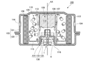
- FIG. 1 is a diagram showing a schematic configuration of a gas generator including the igniter assembly according to the first embodiment.
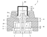
- FIG. 2 is a diagram showing a schematic configuration of the igniter assembly according to the first embodiment.
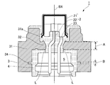
- FIG. 3 is a diagram showing a schematic configuration of the igniter assembly according to the second embodiment.
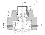
- FIG. 4 is a diagram showing a schematic configuration of the igniter assembly according to the first modification of the second embodiment.
- FIG. 5 is a diagram showing a schematic configuration of the igniter assembly according to the second modification of the second embodiment.
- FIG. 6 is a diagram showing a schematic configuration of a gas generator according to the third embodiment.
- FIG. 1 is an axial sectional view of an airbag gas generator (hereinafter referred to as “gas generator”) 100 using the igniter assembly 1 according to the first embodiment.
- gas generator an airbag gas generator
- FIG. 1 the central axis AX of the gas generator 100 is shown by a alternate long and short dash line.
- the gas generator 100 is not limited to airbags, but may have a known shape suitable for seatbelt pretensioners and curtain airbags, and is known to be used for various actuators and the like. It may be in shape.
- the gas generator 100 includes an upper shell 101 (an example of the "first shell” in the present application) and a lower shell 102 (an example of the "second shell” in the present application).
- the upper shell 101 and the lower shell 102 are made of metal and have a bottomed substantially cylindrical shape. Further, the upper shell 101 is formed with a plurality of gas discharge ports 104 arranged side by side in the circumferential direction. In the gas generator 100, the upper shell 101 and the lower shell 102 are joined to each other with their open ends facing each other, so that both ends in the axial direction are closed to form a short cylindrical housing 103 (referred to as "the present application"). An example of "outer shell container”) is formed.
- the igniter assembly 1 is arranged in the housing 103. Before the operation of the igniter assembly 1, the gas discharge port 104 is closed from the inside of the housing 103 with an aluminum sealing tape 114.
- the gas generating agent 105 filled in the housing 103 is ignited and burned by the operation of the igniter main body 2 (see FIG. 2) included in the igniter assembly 1. For example, it generates combustion gas for inflating an airbag (bag body).
- the inner cylinder member 108 is arranged in the center of the housing 103.
- a plurality of fire transmission holes 107 are provided on the peripheral wall of the inner cylinder member 108.
- a space 109 for accommodating the igniter assembly 1 and the explosive charge 111 is formed inside the inner cylinder member 108.
- the fire transmission hole 107 is closed by the aluminum sealing tape 113. As a result, the airtightness inside the inner cylinder member 108 is ensured.
- a combustion chamber 110 for accommodating the gas generating agent 105 is formed on the outer side in the radial direction of the inner cylinder member 108.
- the gas generating agent 105 is supported by an underplate 115 formed in a substantially ring shape in the combustion chamber 110.
- the propellant 111 a gas generator having good ignitability and a higher combustion temperature than the gas generator 105 can be used.
- the combustion temperature of the propellant 111 is preferably in the range of 1700 to 3000 ° C.
- a power transfer agent 111 known ones containing, for example, nitroguanidine (34% by weight) and strontium nitrate (56% by weight) can be used.
- a known black powder boron saltpeter
- the gas generating agent 105 a gas generating agent having a relatively low combustion temperature can be used.
- the combustion temperature of the gas generating agent 105 is preferably in the range of 1000 to 1700 ° C., for example, guanidine nitrate ( 41% by weight), basic copper nitrate (49% by weight) and known substances containing binders and additives can be used.
- the igniter assembly 1 is fixed to the lower shell 102 side of the inner cylinder member 108.
- a mounting hole 116 is provided in the center of the bottom of the lower shell 102, and the inner cylinder member is in a state where the opening end 108a of the inner cylinder member 108 is exposed to the outside of the lower shell 102 from the mounting hole 116.
- the igniter assembly 1 is inserted into 108. Then, by crimping the opening end portion 108a side of the inner cylinder member 108, the igniter collar 3 (see FIG. 2) of the igniter assembly 1 can be fixed.
- the inner cylinder member 108 is connected to the lower shell 102 by welding or the like in the vicinity of the opening end 108a on the side where the igniter assembly 1 is housed.
- the gas generating agent 105 is housed in the combustion chamber 110, and a filter 106 for collecting the combustion residue contained in the combustion gas generated by the combustion of the gas generating agent 105 and cooling the combustion gas is located outside the gas generating agent 105.
- the filter 106 is formed in a cylindrical shape using a laminated wire mesh or the like, and its outer peripheral surface is arranged so as to face the inner peripheral surface of the housing 103.
- a gap 112, which serves as a gas flow path, is formed between the outer peripheral surface of the filter 106 and the inner peripheral surface of the housing 103, whereby the entire surface of the filter 106 can be used.
- the igniter 111 arranged in the vicinity thereof ignites and burns, and the flame thereof is formed in the inner cylinder member 108. It is ejected from the hole 107 into the combustion chamber 110. This flame ignites and burns the gas generating agent 105 in the combustion chamber 110 to generate combustion gas.
- the combustion gas is filtered and cooled while passing through the filter 106, breaks the sealing tape 114 that closes the gas discharge port 104, and is discharged to the outside from the gas discharge port 104.
- FIG. 2 is an axial sectional view of the igniter assembly 1 according to the present embodiment.
- the central axis BX of the igniter assembly 1 is shown by a alternate long and short dash line.
- the central axis BX of the igniter assembly 1 and the central axis AX of the gas generator 100 coincide with each other.
- the direction along the central axis BX of the igniter assembly 1 is the vertical direction of the igniter assembly
- the upper part of the paper in FIG. 2 is the upper side of the igniter assembly 1
- the opposite side is FIG.
- the lower side of the paper surface is the lower side of the igniter assembly 1.
- the igniter assembly 1 includes an igniter body 2.
- the igniter main body 2 has an ignition portion 21 filled with an igniting agent, and conductive pins 22 and 23 extending from the ignition portion 21 (an example of the “conductive portion” in the present application).
- the igniter main body 2 is an electric ignition type that burns the igniting agent in the ignition portion 21 by the ignition current supplied from the conductive pins 22 and 23.
- the ignition unit 21 has a cup, and a space for accommodating the ignition charge is defined inside.
- the ignition portion 21 is arranged so that a portion corresponding to the bottom of the cup is located on the emission direction side of the combustion product of the igniting agent when the igniter main body 2 is operated.
- the igniter assembly 1 is arranged in the housing 103 so that the portion corresponding to the bottom of the cup faces the filling position of the explosive charge 111.
- the conductive pins 22 and 23 are connected with a bridge wire (not shown) in the ignition portion 21 while being electrically insulated from each other.
- the igniter filled in the ignition portion 21 is in contact with a bridge wire (not shown) connected to the conductive pins 22 and 23.
- the igniter is ignited and burned by the heat generated by the bridge wire, which produces a combustion product. In this way, the igniter body 2 burns the igniter and releases the combustion product.
- the igniter assembly 1 includes a metal igniter collar 3.
- the igniter collar 3 has a cylindrical peripheral wall portion 31 that surrounds the igniter body 2.
- the central axis of the peripheral wall portion 31 coincides with the central axis BX of the igniter assembly 1.
- the inner diameter of the peripheral wall portion 31 is formed to be larger than the outer diameter of the ignition portion 21 of the igniter main body 2.
- the peripheral wall portion 31 of the igniter collar 3 is located on the tip side of the conductive pins 22 and 23 from below the middle of the ignition portion 21. It surrounds the igniter main body 2 over.
- the peripheral wall portion 31 may be formed with dimensions that can at least surround the conductive pins 22 and 23, and may be arranged so as to surround at least the conductive pins 22 and 23.
- the igniter assembly 1 includes a resin molded body 4 that is interposed between the igniter main body 2 and the igniter collar 3 and integrates the igniter main body 2 and the igniter collar 3.
- the resin molded body 4 is formed so as to be continuously interposed between the igniter main body 2 and the igniter collar 3 by injection molding a resin material in the manufacturing process of the igniter assembly 1.
- a resin material having excellent heat resistance, durability, corrosion resistance and the like after curing can be preferably used.
- thermoplastic resins such as polybutylene terephthalate resin, polyethylene terephthalate resin, polyamide resin, polypropylene sulfide resin and polypropylene oxide resin, and thermosetting resins such as epoxy resin.
- the resin molded body 4 may be formed so as to cover the entire circumference of the ignition portion 21.
- the igniter collar 3 is provided on the inner peripheral portion 31a of the peripheral wall portion 31, and has a first support portion 32 formed to be convex inward in the radial direction of the peripheral wall portion 31 so as to be embedded in the resin molded body 4. Have.
- the igniter collar 3 is integrally formed with the first support portion 32 by casting. Further, the first support portion 32 is continuously formed along the circumferential direction of the peripheral wall portion 31. When viewed in the direction along the central axis BX, the first support portion 32 extends to a position below the ignition portion 21 of the igniter main body 2 and overlapping the ignition portion 21. That is, the outer diameter of the ignition portion 21 is larger than the inner diameter of the first support portion 32.
- the igniter assembly 1 is configured so that the ignition portion 21 of the igniter main body 2 cannot pass below the first support portion 32. Therefore, the igniter main body 2 operates, the pressure and temperature on the upper side of the igniter assembly 1 (inside the inner cylinder member 108 shown in FIG. 1) rise, the resin molded body 4 softens, and the igniter assembly 1 Even when a downward force acts on the igniter, it is possible to prevent the ignition portion 21 from passing through the first support portion 32 and jumping out from below the igniter collar 3.
- a plurality of first support portions 32 may be discontinuously formed along the circumferential direction as long as the passage of the ignition portion 21 can be suppressed.
- the igniter collar 3 is provided on the resin molded body 4 at a position of the inner peripheral portion 31a at a position farther from the ignition portion 21 than the first support portion 32 in the direction along the central axis of the peripheral wall portion 31. It has a second support portion 33 formed to be convex inward in the radial direction of the peripheral wall portion 31 so as to be buried. In the radial direction of the peripheral wall portion 31, the second support portion 33 is formed shorter than the first support portion 32. That is, the second support portion 33 is formed so that the length of the peripheral wall portion 31 that is convex inward in the radial direction is shorter than that of the first support portion 32.
- the second support portion 33 is integrally formed with the igniter collar 3 by pushing the mold so as to scrape off the igniter collar 3 from the lower side of the igniter collar 3. Further, a plurality of second support portions 33 are discontinuously formed along the circumferential direction of the peripheral wall portion 31. In the igniter assembly 1, a plurality of second support portions 33 are formed discontinuously along the circumferential direction of the peripheral wall portion 31, so that the resin is formed with respect to the igniter collar 3 after the resin of the resin molded body 4 is cured. It is possible to prevent the molded body 4 from rotating.
- the resin molded body 4 at the portion forming the connector connection space 5 is integrally formed with the resin molded body 4 at the portion surrounding the ignition portion 21 above the first support portion 32.
- the second support portion 33 is formed at a position facing the connector connection space 5.
- the connector connection space 5 can easily secure a predetermined dimension in the radial direction of the peripheral wall portion 31 and the direction along the central axis. Therefore, in the igniter assembly 1 according to the present embodiment, the connector connection space 5 makes it easy to secure a space for forming the second support portion 33 which is convex inward in the radial direction of the peripheral wall portion 31.
- the igniter assembly 1 configured in this way receives an impact when the igniter body 2 operates when a thin portion exists in the portion of the resin molded body 4 forming the connector connection space 5. Cracks are likely to occur in the portion where the thickness of the resin molded body 4 is the thinnest.
- the portion where the thickness of the resin molded body 4 is the thinnest is represented by a virtual line L indicated by a dotted line. If a crack is generated in the portion indicated by the virtual line L, the resin molded body 4 is separated vertically with the virtual line L as a boundary. Since the resin molded body 4 above the virtual line L is supported by the first support portion 32, it is suppressed from moving below the igniter assembly 1.
- the resin molded body 4 below the virtual line L is supported by the second support portion 33 arranged below the first support portion 32, it moves below the igniter assembly 1. Is suppressed. As a result, in the igniter assembly 1 according to the present embodiment, even if the resin molded body 4 is cracked and separated, a part of the resin molded body 4 is outside the igniter assembly 1. It is possible to prevent it from popping out.
- the minimum dimension of the first support portion 32 in the direction along the central axis of the peripheral wall portion 31 is A
- the minimum dimension of the second support portion 33 in the direction along the central axis is B.
- the minimum dimension A of the first support portion 32 is larger than the minimum dimension B of the second support portion 33.
- the minimum dimension A of the first support portion 32 is equal to or larger than the minimum dimension B of the second support portion 33.
- the second support portion 33 can prevent a part of the body 4 from jumping out of the igniter assembly 1.
- most of the material constituting the igniter main body 2 is metal, and it is necessary to increase the minimum dimension of the first support portion 32 to prevent deformation or the like in order to prevent the igniter main body 2 from popping out. ..
- the minimum dimension A of the first support portion 32 is equal to or greater than the minimum dimension B of the second support portion 33, the effect of suppressing popping out of the igniter main body 2 can be enhanced.
- the igniter assembly according to the present embodiment suppresses a part of the resin molded body 4 from jumping out of the igniter assembly 1 even when the resin molded body 4 is cracked. can.
- the withstand voltage performance can be improved.
- FIG. 3 is an axial sectional view of the igniter assembly 1 according to the present embodiment.
- the same reference numerals are given to the configurations substantially the same as those of the above-described first embodiment, and the description thereof will be omitted.
- the igniter assembly 1 according to the present embodiment shown in FIG. 3 is basically different from the igniter assembly 1 according to the first embodiment shown in FIG. 2 except that the configuration of the second support portion is different. It has the same structure.
- the igniter collar 3 of the igniter assembly 1 has a second support portion 34 formed in a concave shape toward the radial outer side of the peripheral wall portion 31 so that the resin molded body 4 is filled inside.
- the second support portion 34 is a hole formed by a drill from the inner peripheral portion 31a side of the igniter collar 3.
- the resin molded body 4 below the virtual line L is supported by the second support portion 34 arranged below the first support portion 32.
- the igniter assembly 1 according to the present embodiment is a part of the resin molded body 4 (connector connection space) even if a crack occurs along the virtual line L in the resin molded body 4 and the resin molded body 4 is separated. Since it is possible to prevent the resin molded body 4) of the formed portion from jumping out to the outside of the igniter assembly 1, the withstand voltage performance can be improved.
- the minimum dimension of the first support portion 32 in the direction along the central axis of the peripheral wall portion 31 is A
- the minimum dimension of the second support portion 34 in the direction along the central axis is B.
- the minimum dimension A of the first support portion 32 is larger than the minimum dimension B of the second support portion 34.
- the minimum dimension A of the first support portion 32 is equal to or larger than the minimum dimension B of the second support portion 34.
- the concave second support portion 34 may be a hole penetrating the peripheral wall portion 31.
- the through hole may be formed by a punch in the peripheral wall portion 31 of the igniter collar 3.
- the igniter assembly 1 can also prevent a part of the resin molded body 4 from jumping out of the igniter assembly 1 by the second support portion 34 formed of the through hole.
- a plurality of second support portions 34 may be discontinuously formed along the circumferential direction of the peripheral wall portion 31. This makes it possible to prevent the resin molded body 4 from rotating with respect to the igniter collar 3 after the resin molded body 4 is cured of the resin.
- FIG. 4 is an axial sectional view of the igniter assembly 1 according to the present modification.
- the second support portion 34 is configured by a through hole penetrating the peripheral wall portion 31.
- the resin molded body 4 has a protruding portion 40 that protrudes radially outward from the outer peripheral portion 31b of the peripheral wall portion 31 in a triangular shape.
- the protrusion 40 prevents the igniter assembly 1 from rotating with respect to the inner cylinder member 108 during the step of crimping the open end 108a after being inserted into the inner cylinder member 108 of the gas generator 100 shown in FIG.
- the protrusion 40 forms the maximum diameter of the igniter assembly 1, and even if the igniter assembly 1 is inserted into the inner cylinder member 108, the metal igniter collar becomes the inner cylinder member 108. Interference can be prevented, and the rotation of the igniter assembly 1 with respect to the gas generator 100 can be sufficiently prevented and held.
- FIG. 5 is an axial sectional view of the igniter assembly 1 according to the present modification.
- the second support portion 34 is configured by a through hole penetrating the peripheral wall portion 31.
- the resin molded body 4 has a protrusion 41 radially outward from the outer peripheral portion 31b of the peripheral wall portion 31.
- the protruding portion 41 is formed so as to cover the entire outer peripheral portion 31b. Further, the protruding portion 41 has a tapered shape in which the diameter on the upper side is reduced so that the igniter assembly 1 can be easily inserted into the inner cylinder member 108.
- the protrusion 41 is used by the igniter assembly 1 during the step of crimping the open end 108a after being inserted into the inner cylinder member 108 of the gas generator 100 shown in FIG. It has a function of increasing the frictional force so as not to rotate with respect to the inner cylinder member 108.
- the protrusion 41 forms the maximum diameter of the igniter assembly 1, and even if the igniter assembly 1 is inserted into the inner cylinder member 108, the metal igniter collar becomes the inner cylinder member 108. Interference can be prevented, and the rotation of the igniter assembly 1 with respect to the gas generator 100 can be sufficiently prevented and held.
- FIG. 6 is an axial sectional view of the gas generator 100 according to the present embodiment.
- the same reference numerals are given to the configurations substantially the same as those of the above-described first embodiment, and the description thereof will be omitted.
- the housing 103 has an upper shell 101 (an example of the “first shell” in the present application) and a lower shell 120 (“second shell” in the present application), similarly to the first embodiment described above. It is formed by combining an example of "shell”).
- the lower shell 120 is made of metal and has a substantially cylindrical shape with a bottom, similar to the lower shell 102 in the first embodiment.
- a part of the lower shell 120 is the igniter collar of the igniter assembly 1.
- the lower shell 120 is provided with an igniter collar 130 so as to extend from the mounting hole 116 to the upper side (upper shell 101 side) of the central axis AX.
- the igniter collar 130 is formed to fit inside the inner cylinder member 108, and is attached to the inner peripheral surface of the inner cylinder member 108 by welding or the like.
- the inner cylinder member 108 is fixed to the igniter collar 130.
- the inner cylinder member 108 may be fixed to the igniter collar 130 by caulking or press-fitting the inner cylinder member 108 to the igniter collar 130.
- the igniter assembly 1 is fixed to the igniter collar 130 by the resin molded body 4.
- the igniter collar 130 is provided on the inner peripheral portion of the peripheral wall portion 131, and is radially inward at the upper end of the peripheral wall portion 131 so as to be buried in the resin molded body 4. It has a first support portion 132 formed in a convex shape.
- the first support portion 132 has the same shape and function as the first support portion 32 in the first embodiment.
- the igniter collar 130 is provided at a position of the inner peripheral portion that is farther from the ignition portion than the first support portion 132 in the direction along the central axis of the peripheral wall portion 131, and is embedded in the resin molded body 4. It has a second support portion 133 formed so as to be convex inward in the radial direction of the peripheral wall portion 131.
- the second support portion 133 is provided separately from the igniter collar 130, and is fixed to the peripheral wall portion 131 by welding or snap-fitting.
- the second support portion 133 is embedded in the resin molded body 4 by injection molding the resin molded body 4 in a state where the second support portion 133 is fixed to the igniter collar 130.
- the second support portion 133 functions in the same manner as the second support portion 33 in the first embodiment.
- the second support portion 133 may be integrally formed with the igniter collar 130 like the second support portion 33 in the first embodiment, or may be internally formed like the second support portion 34 in the second embodiment. It may be a hole formed in a concave shape toward the radial outer side of the peripheral wall portion 131 so that the resin molded body 4 is filled in, or may be a through hole.
- the igniter collar 130 can be provided with the first support portion and the second support portion. Therefore, according to the gas generator 100 according to the present embodiment, it is possible to prevent a part of the resin molded body 4 from jumping out to the outside of the igniter assembly 1, so that the pressure resistance performance can be improved.
- the minimum dimension of the first support portion 132 in the direction along the central axis of the peripheral wall portion 131 is larger than the minimum dimension of the second support portion 133. It should be noted that preferably, the minimum dimension of the first support portion 132 is equal to or larger than the minimum dimension B of the second support portion 133.
- the gas generator in the above embodiment has a disk shape whose length in the height direction is shorter than the outer diameter in the top view, but for example, the length in the axial direction is smaller than the outer diameter in the top view.
- the technique of the present disclosure may be applied to a gas generator having a long cylinder shape.
- the gas generator in the above embodiment includes a gas generator as a gas source, but the present invention is not limited to this, and the gas generator may include a compressed gas as a gas source.
- the igniter assembly of the above embodiment can also be used in a gas generator filled with compressed gas.
- the second support portions 33, 34, 133 may be continuously formed along the circumferential direction of the peripheral wall portion of the igniter collar.
- a part of the upper shell 101 is the igniter collar 130, and the igniter assembly 1 is partially fixed to the upper shell 101 which is the igniter collar 130 by the resin molded body 4. You may.
- Ignition assembly 2 Ignition body 3: Ignition color 4: Resin molded body 5: Connector connection space 21: Ignition part 22: Conductive pin 23: Conductive pin 31: Peripheral wall part 31a: Inner peripheral part 31b: Outer circumference Part 32: First support part 33: Second support part 100: Gas generator 101: Upper shell 102: Lower shell 103: Housing 104: Gas outlet 105: Gas generator 106: Filter 107: Fire transmission hole 108: Inside Cylinder member 109: Space 110: Combustion chamber 111: Explosive agent 112: Gap 113: Seal tape 114: Seal tape 115: Under plate 116: Mounting hole 120: Lower shell 130: Ignition collar 131: Peripheral wall portion 132: First support Part 133: Second support part
Landscapes
- Physics & Mathematics (AREA)
- Fluid Mechanics (AREA)
- Engineering & Computer Science (AREA)
- Mechanical Engineering (AREA)
- Air Bags (AREA)
- Feeding, Discharge, Calcimining, Fusing, And Gas-Generation Devices (AREA)
Priority Applications (3)
| Application Number | Priority Date | Filing Date | Title |
|---|---|---|---|
| CN202180034590.8A CN115551747B (zh) | 2020-05-14 | 2021-05-10 | 点火器组装体以及具备该点火器组装体的气体发生器 |
| DE112021002770.0T DE112021002770T5 (de) | 2020-05-14 | 2021-05-10 | Zünderbaugruppe und Gasgenerator, der mit einer solchen vorgesehen ist |
| US17/924,498 US11993222B2 (en) | 2020-05-14 | 2021-05-10 | Igniter assembly and gas generator provided with same |
Applications Claiming Priority (2)
| Application Number | Priority Date | Filing Date | Title |
|---|---|---|---|
| JP2020-085501 | 2020-05-14 | ||
| JP2020085501A JP7428585B2 (ja) | 2020-05-14 | 2020-05-14 | 点火器組立体及びそれを備えるガス発生器 |
Publications (1)
| Publication Number | Publication Date |
|---|---|
| WO2021230197A1 true WO2021230197A1 (ja) | 2021-11-18 |
Family
ID=78510865
Family Applications (1)
| Application Number | Title | Priority Date | Filing Date |
|---|---|---|---|
| PCT/JP2021/017691 Ceased WO2021230197A1 (ja) | 2020-05-14 | 2021-05-10 | 点火器組立体及びそれを備えるガス発生器 |
Country Status (4)
| Country | Link |
|---|---|
| US (1) | US11993222B2 (enExample) |
| JP (1) | JP7428585B2 (enExample) |
| DE (1) | DE112021002770T5 (enExample) |
| WO (1) | WO2021230197A1 (enExample) |
Families Citing this family (1)
| Publication number | Priority date | Publication date | Assignee | Title |
|---|---|---|---|---|
| CN115782806A (zh) * | 2022-11-25 | 2023-03-14 | 延锋汽车智能安全系统有限责任公司 | 点火系统及其制造方法、气体发生器和安全气囊 |
Citations (5)
| Publication number | Priority date | Publication date | Assignee | Title |
|---|---|---|---|---|
| JP2001165600A (ja) * | 1999-09-27 | 2001-06-22 | Daicel Chem Ind Ltd | イニシエータ組立体 |
| JP2002054895A (ja) * | 2000-08-09 | 2002-02-20 | Daicel Chem Ind Ltd | 電気式イニシエータ及びそれを用いたイニシエータ組立体 |
| JP2006234369A (ja) * | 2005-02-28 | 2006-09-07 | Daicel Chem Ind Ltd | 点火器組立体 |
| JP3134281U (ja) * | 2007-05-29 | 2007-08-09 | 日本化薬株式会社 | 点火器組立体及びガス発生器 |
| JP3134430U (ja) * | 2007-05-30 | 2007-08-16 | 日本化薬株式会社 | 点火器組立体およびこれを備えたガス発生器 |
Family Cites Families (4)
| Publication number | Priority date | Publication date | Assignee | Title |
|---|---|---|---|---|
| JP4916868B2 (ja) * | 2006-12-20 | 2012-04-18 | 株式会社ダイセル | 電気的な着火を利用する装置の組立方法 |
| JP2009133514A (ja) * | 2007-11-29 | 2009-06-18 | Daicel Chem Ind Ltd | 電気的な着火を利用する装置の組立方法 |
| JP6250434B2 (ja) | 2014-02-25 | 2017-12-20 | 日本化薬株式会社 | ガス発生器 |
| JP7315410B2 (ja) * | 2019-08-09 | 2023-07-26 | 株式会社ダイセル | ガス発生器 |
-
2020
- 2020-05-14 JP JP2020085501A patent/JP7428585B2/ja active Active
-
2021
- 2021-05-10 DE DE112021002770.0T patent/DE112021002770T5/de active Pending
- 2021-05-10 US US17/924,498 patent/US11993222B2/en active Active
- 2021-05-10 WO PCT/JP2021/017691 patent/WO2021230197A1/ja not_active Ceased
Patent Citations (5)
| Publication number | Priority date | Publication date | Assignee | Title |
|---|---|---|---|---|
| JP2001165600A (ja) * | 1999-09-27 | 2001-06-22 | Daicel Chem Ind Ltd | イニシエータ組立体 |
| JP2002054895A (ja) * | 2000-08-09 | 2002-02-20 | Daicel Chem Ind Ltd | 電気式イニシエータ及びそれを用いたイニシエータ組立体 |
| JP2006234369A (ja) * | 2005-02-28 | 2006-09-07 | Daicel Chem Ind Ltd | 点火器組立体 |
| JP3134281U (ja) * | 2007-05-29 | 2007-08-09 | 日本化薬株式会社 | 点火器組立体及びガス発生器 |
| JP3134430U (ja) * | 2007-05-30 | 2007-08-16 | 日本化薬株式会社 | 点火器組立体およびこれを備えたガス発生器 |
Also Published As
| Publication number | Publication date |
|---|---|
| US20230271586A1 (en) | 2023-08-31 |
| US11993222B2 (en) | 2024-05-28 |
| CN115551747A (zh) | 2022-12-30 |
| JP2021178595A (ja) | 2021-11-18 |
| DE112021002770T5 (de) | 2023-04-06 |
| JP7428585B2 (ja) | 2024-02-06 |
Similar Documents
| Publication | Publication Date | Title |
|---|---|---|
| CN1140765C (zh) | 点火器总成 | |
| EP1424249B1 (en) | Gas generator | |
| JP7470845B2 (ja) | ガス発生器 | |
| EP1541429B1 (en) | Gas generator | |
| JP2009137402A (ja) | ガス発生器 | |
| US12038258B2 (en) | Igniter assembly and method for assembling igniter assembly | |
| WO2021230197A1 (ja) | 点火器組立体及びそれを備えるガス発生器 | |
| CN116917167A (zh) | 点火器组装体以及气体发生器 | |
| JP2002090097A (ja) | イニシエータ組立体及びこれを用いたガス発生器 | |
| JP6954520B2 (ja) | 点火器組立体、及びガス発生器 | |
| US20250206254A1 (en) | Igniter Assembly and Gas Generation Device | |
| CN113043989B (zh) | 气体发生器 | |
| CN115551747B (zh) | 点火器组装体以及具备该点火器组装体的气体发生器 | |
| JP7534871B2 (ja) | ガス発生器及びその製造方法 | |
| JP2000329500A (ja) | スクイブ | |
| JP5305991B2 (ja) | 小型ガス発生器 | |
| US20250091544A1 (en) | Gas generator | |
| JP2000292099A (ja) | スクイブ、及びスクイブ装置 | |
| JP2023133020A (ja) | 点火装置 | |
| JP2021195099A (ja) | ガス発生器 | |
| JP2000292098A (ja) | スクイブ |
Legal Events
| Date | Code | Title | Description |
|---|---|---|---|
| 121 | Ep: the epo has been informed by wipo that ep was designated in this application |
Ref document number: 21803167 Country of ref document: EP Kind code of ref document: A1 |
|
| 122 | Ep: pct application non-entry in european phase |
Ref document number: 21803167 Country of ref document: EP Kind code of ref document: A1 |