WO2021225084A1 - 損傷評価装置、方法及びプログラム - Google Patents
損傷評価装置、方法及びプログラム Download PDFInfo
- Publication number
- WO2021225084A1 WO2021225084A1 PCT/JP2021/016627 JP2021016627W WO2021225084A1 WO 2021225084 A1 WO2021225084 A1 WO 2021225084A1 JP 2021016627 W JP2021016627 W JP 2021016627W WO 2021225084 A1 WO2021225084 A1 WO 2021225084A1
- Authority
- WO
- WIPO (PCT)
- Prior art keywords
- damage
- specific
- image
- cracks
- crack
- Prior art date
- Legal status (The legal status is an assumption and is not a legal conclusion. Google has not performed a legal analysis and makes no representation as to the accuracy of the status listed.)
- Ceased
Links
Images


Classifications
-
- G—PHYSICS
- G06—COMPUTING OR CALCULATING; COUNTING
- G06T—IMAGE DATA PROCESSING OR GENERATION, IN GENERAL
- G06T7/00—Image analysis
- G06T7/0002—Inspection of images, e.g. flaw detection
-
- G—PHYSICS
- G06—COMPUTING OR CALCULATING; COUNTING
- G06T—IMAGE DATA PROCESSING OR GENERATION, IN GENERAL
- G06T7/00—Image analysis
- G06T7/0002—Inspection of images, e.g. flaw detection
- G06T7/0004—Industrial image inspection
- G06T7/001—Industrial image inspection using an image reference approach
-
- G—PHYSICS
- G06—COMPUTING OR CALCULATING; COUNTING
- G06T—IMAGE DATA PROCESSING OR GENERATION, IN GENERAL
- G06T11/00—Two-dimensional [2D] image generation
- G06T11/60—Creating or editing images; Combining images with text
-
- G—PHYSICS
- G06—COMPUTING OR CALCULATING; COUNTING
- G06T—IMAGE DATA PROCESSING OR GENERATION, IN GENERAL
- G06T7/00—Image analysis
- G06T7/60—Analysis of geometric attributes
-
- G—PHYSICS
- G06—COMPUTING OR CALCULATING; COUNTING
- G06V—IMAGE OR VIDEO RECOGNITION OR UNDERSTANDING
- G06V10/00—Arrangements for image or video recognition or understanding
- G06V10/98—Detection or correction of errors, e.g. by rescanning the pattern or by human intervention; Evaluation of the quality of the acquired patterns
- G06V10/993—Evaluation of the quality of the acquired pattern
-
- G—PHYSICS
- G01—MEASURING; TESTING
- G01N—INVESTIGATING OR ANALYSING MATERIALS BY DETERMINING THEIR CHEMICAL OR PHYSICAL PROPERTIES
- G01N21/00—Investigating or analysing materials by the use of optical means, i.e. using sub-millimetre waves, infrared, visible or ultraviolet light
- G01N21/84—Systems specially adapted for particular applications
- G01N21/88—Investigating the presence of flaws or contamination
- G01N21/8851—Scan or image signal processing specially adapted therefor, e.g. for scan signal adjustment, for detecting different kinds of defects, for compensating for structures, markings, edges
- G01N2021/8883—Scan or image signal processing specially adapted therefor, e.g. for scan signal adjustment, for detecting different kinds of defects, for compensating for structures, markings, edges involving the calculation of gauges, generating models
-
- G—PHYSICS
- G06—COMPUTING OR CALCULATING; COUNTING
- G06T—IMAGE DATA PROCESSING OR GENERATION, IN GENERAL
- G06T2207/00—Indexing scheme for image analysis or image enhancement
- G06T2207/10—Image acquisition modality
- G06T2207/10032—Satellite or aerial image; Remote sensing
-
- G—PHYSICS
- G06—COMPUTING OR CALCULATING; COUNTING
- G06T—IMAGE DATA PROCESSING OR GENERATION, IN GENERAL
- G06T2207/00—Indexing scheme for image analysis or image enhancement
- G06T2207/20—Special algorithmic details
- G06T2207/20081—Training; Learning
-
- G—PHYSICS
- G06—COMPUTING OR CALCULATING; COUNTING
- G06T—IMAGE DATA PROCESSING OR GENERATION, IN GENERAL
- G06T2207/00—Indexing scheme for image analysis or image enhancement
- G06T2207/20—Special algorithmic details
- G06T2207/20084—Artificial neural networks [ANN]
-
- G—PHYSICS
- G06—COMPUTING OR CALCULATING; COUNTING
- G06T—IMAGE DATA PROCESSING OR GENERATION, IN GENERAL
- G06T2207/00—Indexing scheme for image analysis or image enhancement
- G06T2207/20—Special algorithmic details
- G06T2207/20092—Interactive image processing based on input by user
- G06T2207/20096—Interactive definition of curve of interest
-
- G—PHYSICS
- G06—COMPUTING OR CALCULATING; COUNTING
- G06T—IMAGE DATA PROCESSING OR GENERATION, IN GENERAL
- G06T2207/00—Indexing scheme for image analysis or image enhancement
- G06T2207/30—Subject of image; Context of image processing
- G06T2207/30108—Industrial image inspection
- G06T2207/30132—Masonry; Concrete
-
- G—PHYSICS
- G06—COMPUTING OR CALCULATING; COUNTING
- G06T—IMAGE DATA PROCESSING OR GENERATION, IN GENERAL
- G06T2207/00—Indexing scheme for image analysis or image enhancement
- G06T2207/30—Subject of image; Context of image processing
- G06T2207/30181—Earth observation
- G06T2207/30184—Infrastructure
Definitions
- the present invention relates to a damage evaluation device, a method and a program, and particularly relates to a technique for evaluating a structure damage that occurs in connection with the construction of the structure.
- Non-Patent Document 1 it has been proposed to visually evaluate defects that occur in the surface layer of a newly constructed structure and utilize them for validation of construction methods and improvement of construction methods.
- Patent Document 1 an image showing the surface of a structure is image-analyzed to detect cracks on the surface of the structure, and the feature amounts of the detected cracks (crack direction, length, width, edge strength, and edge strength, and (Edge density, etc.) is detected, each crack is grouped based on the detected feature amount, and when displaying a crack image filled with cracks, the crack image is displayed using a different line type or color for each group.
- the image processing method is described.
- the tunnel lining surface image acquired in chronological order can be compared, and the tunnel lining surface image of this time can be corrected so that even a crack changed by about several mm can be recognized.
- the image correction method is described.
- the tunnel lining surface image correction method described in Patent Document 2 detects a position-invariant installation object or joint on the tunnel lining surface, performs image processing to match the positions of the installation object or joint between different time-series images, and performs image processing. By generating a tunnel lining surface image whose position is normalized, the tunnel lining surface image used for time-series management of deformation is corrected.
- Patent Document 1 describes that cracks on the surface of a structure are grouped based on the detected features of the cracks, but there is no description of selecting damages that occur in connection with the construction of the structure.
- Patent Document 2 describes that joints are detected together with cracks in a concrete structure, but the joints whose positions do not change are image processed to match the previous tunnel lining surface image with the current tunnel lining surface image ( It is used to perform affine transformation), not to screen for damage.
- the present invention has been made in view of such circumstances, and provides a damage evaluation device, method and program capable of automatically evaluating damage to the surface layer of a structure that occurs in connection with the construction of the structure.
- the purpose is a damage evaluation device, method and program capable of automatically evaluating damage to the surface layer of a structure that occurs in connection with the construction of the structure.
- the invention according to the first aspect is a damage evaluation device for a structure provided with a processor, wherein the processor acquires an image of the structure and obtains an image.
- Damage detection processing that detects damage to the structure based on it
- feature area detection processing that detects the feature area of the structure related to the construction of the structure based on the acquired image
- the detected structure among the detected damages A sorting process for selecting specific damages related to the characteristic area and an information output processing for outputting information on the selected specific damages are performed.
- the specific damages related to the structure feature area related to the construction of the structure are automatically selected. Since the information on the selected specific damage is output, it is possible to automatically evaluate the damage on the surface layer of the structure that occurs in connection with the construction of the structure, and it is possible to verify the validity of the construction method and improve the construction method. It can be utilized.
- the damage detection process is executed by a first trained model that outputs an area of each damage as a recognition result for each damage of the structure when an image is input. ..
- the damage to the structure is a crack in the structure
- the specific damage is a specific crack generated due to the construction of the structure among the cracks in the structure.
- Specific cracks include, for example, sinking cracks and crescent cracks that occur in the surface layer of a concrete structure.
- the feature region detection process is executed by the second trained model that outputs the structure feature region as a recognition result when an image is input.
- the structure feature region is a region showing a construction mark related to a specific crack which is a specific damage generated due to the construction of the structure.
- Construction marks related to specific cracks are, for example, P-concrete marks, joints, and joints on the surface layer of a concrete structure.
- the sorting process sorts damage that comes into contact with the structure feature region or damage that overlaps with the structure feature region as specific damage.
- the sorting process includes an expansion process for expanding the size of the structure feature region, and the damage or the expanded structure in contact with the expanded structure feature region. It is preferable to select the damage that overlaps the feature area as a specific damage.
- the rate or amount of expansion of the size of the structure feature region may be a preset value or a value appropriately set by the user.
- the processor performs a size specifying process for specifying the size of the specific damage.
- the damage to the structure includes a crack in the structure, and the specific damage is a specific crack generated due to the construction of the structure among the cracks in the structure.
- the relative length between the length on the image of the specific crack and the length on the image of the structure feature region can be calculated, and the calculated relative length can be set as the size of the specific damage.
- the damage to the structure includes a crack in the structure
- the specific damage is a specific crack generated due to the construction of the structure among the cracks in the structure. Therefore, in the size specifying process, it is preferable to calculate the actual size of the specific damage based on the length on the image of the specific crack, the length on the image of the structure feature area, and the actual size of the structure feature area.
- the damage to the structure includes a crack in the structure, and the specific damage is a specific crack generated due to the construction of the structure among the cracks in the structure.
- the image captures a structure with a scale reference whose actual dimensions are known, and the sizing process is the actual size of the specific damage based on the length on the image of the specific crack and the length on the image of the scale reference. It is preferable to calculate the size.
- the damage to the structure includes a crack in the structure
- the specific damage is a specific crack generated due to the construction of the structure among the cracks in the structure. Therefore, in the size specifying process, it is preferable to calculate the actual size of the specific damage based on the length of the specific crack on the image, the shooting conditions of the camera that captured the image, and the camera information.
- the shooting conditions of the camera include, for example, the distance between the camera and the specific crack
- the camera information includes, for example, the focal length, the size of the image sensor, the number of pixels, or the pixel pitch.
- the information output process outputs each specific damage in an identifiable manner according to the attribute of the specific damage.
- Specific damage attributes include damage length, width, area, and so on. Further, it is preferable that each specific damage is color-coded according to the attribute of the specific damage so that the specific damage can be identified by the difference in line type or the like.
- the information output process outputs the structural feature region corresponding to the specific damage in an identifiable manner according to the attribute of the specific damage.
- the processor calculates the ratio between the total number of the structure feature regions and the number of the structure feature regions corresponding to the specific damage, and the information output process calculates the calculated ratio. It is preferable to output.
- the processor gives an editing instruction of at least one of the detected damage detection result and the detected structure feature region detection result from the operation unit operated by the user. It is preferable to perform an editing instruction receiving process for receiving and an editing process for editing the detection result according to the received editing instruction.
- the information output process outputs information on specific damage to a display and displays it, or saves it as a file in a memory.
- the specific damage information includes damage identification information, damage type and size items, and a damage quantity table in which information corresponding to each item is described for each specific damage. Is preferably included.
- the invention according to the nineteenth aspect is a damage evaluation method for evaluating damage to a structure by a processor, and each process of the processor includes a step of acquiring an image of the structure and a structure based on the acquired image.
- the step of detecting the damage of the structure, the step of detecting the structure feature area related to the construction of the structure based on the acquired image, and the specific damage related to the detected structure feature area among the detected damages. Includes a step of sorting out and a step of outputting information on the selected specific damage.
- the invention according to the twentieth aspect is a damage evaluation program for causing a computer to execute a method for evaluating damage to a structure, wherein the method is a step of acquiring an image of a structure and a structure based on the acquired image.
- damage to the surface layer of a structure that occurs in connection with the construction of the structure can be automatically evaluated.
- FIG. 1 is a diagram showing an example of damage to a structure.
- FIG. 2 is a diagram showing an example of a flow from damage detection to selection of specific damage.
- FIG. 3 is a diagram used for explaining a method of selecting whether or not the detected crack is a sinking crack.
- FIG. 4 is a block diagram showing an example of the hardware configuration of the damage evaluation device according to the present invention.
- FIG. 5 is a conceptual diagram showing an embodiment of a damage detection processing unit and a feature area detection processing unit configured by a CPU or the like.
- FIG. 6 is a diagram showing a first display example of an image of a structure to be evaluated and information on specific damage.
- FIG. 7 is a diagram showing a second display example of an image of the structure to be evaluated and information on specific damage.
- FIG. 8 is a diagram showing an example of a display screen in which a color-coded crack image is added to the image shown in FIG. 7 (B).
- FIG. 9 is a diagram showing another example of specific damage related to the structural feature area related to the construction of the structure.
- FIG. 10 is a diagram showing still another example of specific damage related to the structural feature area related to the construction of the structure.
- FIG. 11 is a diagram showing another example of the flow from damage detection to selection of specific damage.
- FIG. 12 is a damage diagram including information on cracks.
- FIG. 13 is a chart showing an example of a damage quantity table included in the damage detection result.
- FIG. 14 is a diagram showing a method of adding vertices to a polyline along a crack.
- FIG. 15 is a diagram showing a method of removing vertices from a polyline along a crack.
- FIG. 16 is a flowchart showing an embodiment of the damage evaluation method according to the present invention.
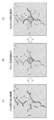
- FIG. 1 is a diagram showing an example of damage to a structure
- FIG. 1 (A) shows an original image of a concrete structure having a construction mark of the structure
- FIG. 1 (B) shows crack detection.
- a composite image in which the result (cracked image) is superimposed and displayed on the original image is created.
- the construction trace of the structure in this example is the trace of a plastic cone (hereinafter referred to as "P-con"), and P on FIG. 1 indicates the trace of P-con.
- P-con trace P will be described.
- FIG. 1 (B) show cracks around the P-con trace P.
- the cracks C1 to C3 are represented by a crack image in which the crack region detected from the original image of FIG. 1 (A) is filled with a specific color.
- Cracks C1 to C3 around the P-con trace P are classified as sinking cracks and are one of the cracks generated due to the construction of the structure.
- the sinking crack is a crack caused by restraining the displacement due to sinking or bleeding after the concrete is poured by the formwork separator, the formwork on the surface, or the like.
- One aspect of the present invention detects damage to a structure from an image of the structure, selects damage related to the construction of the structure (specific damage) from the detected damage, and selects specific damage. Information is output. This makes it possible to utilize it for verification of the validity of the construction method of the structure and improvement of the construction method.
- the structural feature region related to the construction of the structure is the region of the P-con trace P
- the specific damages related to the region of the P-con trace are the sinking cracks C1 to C3.
- FIG. 2 is a diagram showing an example of a flow from damage detection to selection of specific damage.
- damage to the structure is detected based on an image of the structure. Cracks may be detected by artificial intelligence (AI) or by an image processing algorithm.
- AI artificial intelligence
- the structure feature region (in this example, the region of the P-con trace P) related to the construction of the structure is detected based on the photographed image of the structure.
- the region of the P-con trace P may be detected by AI or by an image processing algorithm. Further, it may be detected by accepting a manual instruction input by the user.
- the submerged cracks (specific cracks) C1 to C4 related to the region of the P-con trace P were selected, and the selected submerged cracks C1 to C4 were selected. Is color-coded so that it can be distinguished from other cracks, or the line type is changed and output.
- FIG. 3 is a diagram used to explain a method of selecting whether or not the detected crack is a sinking crack.
- FIG. 3A shows the detected cracks C1 to C3 and the P-con trace P, respectively.
- Whether or not the cracks C1 to C3 are sinking cracks related to the region of the P-con trace P can be determined when the cracks C1 to C3 come into contact with the region of the P-con trace P or the region of the P-con trace P. If it overlaps with, it is sorted as a sinking crack.
- the size of the region of the P-con trace P is expanded to the size of the region of the P-con trace P1.
- the expansion process of the region of the P-con trace P expands the region of the P-con trace P at a constant ratio in the radial direction from the center of the circular P-con trace P, or expands the outer shape of the circular P-con trace P to a constant.
- the rate or amount of expansion of the area of the P-con trace P may be a preset value or a value appropriately set by the user.
- the cracks C1 to C3 are all in contact with the region of the P-con trace P1 or overlap with the region of the P-con trace P1, so that the cracks are sorted as sinking cracks.
- the region of the P-con trace is not limited to the case where the detected P-con region is expanded by the expansion process, and a region slightly wider than the original P-con trace region is detected as the P-con trace region. You may.
- the distance between the cracks C1 to C3 and the region of the P-con trace P1 may be calculated, and if the distance is within the threshold value, it may be selected as a sinking crack.
- FIG. 4 is a block diagram showing an example of the hardware configuration of the damage evaluation device according to the present invention.
- the damage evaluation device 10 shown in FIG. 1 a personal computer or a workstation can be used.
- the damage evaluation device 10 of this example mainly includes an image acquisition unit 12, an image database 14, a storage unit 16, an operation unit 18, a CPU (Central Processing Unit) 20, a RAM (Random Access Memory) 22, and a ROM. It is composed of (Read Only Memory) 24 and a display control unit 26.
- the image acquisition unit 12 corresponds to an input / output interface, and in this example, acquires an image or the like of a structure to be evaluated.
- the structure to be evaluated includes, for example, walls, columns, beams of bridges, tunnels, buildings and the like.
- the image acquired by the image acquisition unit 12 is, for example, a drone (unmanned aerial vehicle) equipped with a camera, a robot, or a large number of images (image group) obtained by manually photographing a structure. It is preferable that the image group covers the entire structure and the adjacent images are overlapped.
- the image group acquired by the image acquisition unit 12 is stored in the image database 14.
- the storage unit 16 is a memory composed of a hard disk device, a flash memory, and the like.
- the storage unit 16 contains a CAD (computer-aided design) data indicating a structure, and a file, in addition to an operating system and a damage evaluation program. Information on the damage done is stored.
- the damage information includes damage evaluation results such as damage images and damage diagrams (CAD data).
- the CAD data of the structure to be evaluated if the CAD data exists in advance, it can be used. When the CAD data of the structure does not exist, it can be automatically created based on the image group stored in the image database 14.
- the feature points between the images overlapping each other in the image group are extracted, and the feature points are mounted on the drone based on the extracted feature points. It is possible to estimate the position and orientation of the camera, and to generate a three-dimensional point cloud model in which the three-dimensional position of the feature point is estimated at the same time from the estimation result of the position and orientation of the camera.
- Structure from Motion Structure from Motion
- Structure from Motion that tracks the movement of many feature points from a group of images in which the shooting position of the camera is moved by the drone, and simultaneously estimates the three-dimensional structure (Structure) and camera posture (Motion) of the structure.
- SfM three-dimensional structure
- bundle adjustment an optimization calculation method called bundle adjustment has been developed, and it has become possible to output with high accuracy.
- CAD data of the structure can be generated based on the generated 3D point cloud model.
- the operation unit 18 includes a keyboard, a mouse, and the like that are connected to the computer by wire or wirelessly, and functions as an operation unit that gives normal operation instructions to the computer.
- the operation unit 18 has a structure detected based on an image of the structure. It functions as an operation unit that edits the detection result of damage to an object and the detection result of a structural feature area such as a P-con trace by a user operation. Details such as editing the damage detection result will be described later.
- the CPU 20 reads various programs stored in the storage unit 16 or the ROM 24 or the like, controls each unit in an integrated manner, and detects damage to the structure based on a photographed image of the structure. Damage detection processing and construction of the structure. Feature area detection process to detect the structure feature area related to (P-con trace area, etc.), selection process to select specific damage related to the structure feature area among the detected damages, and selected identification. Performs information output processing, etc. to output damage information.
- the damage detection process for detecting damage based on the captured image of the structure and the feature area detection process for detecting the feature area of the structure can be performed by AI, respectively.
- a trained model by a convolutional neural network can be used.
- CNN convolutional neural network
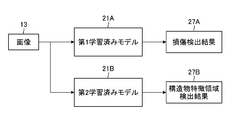
- FIG. 5 is a conceptual diagram showing an embodiment of a damage detection processing unit and a feature area detection processing unit configured by a CPU or the like.
- the damage detection processing unit and the feature area detection processing unit are composed of the first trained model 21A and the second trained model 21B, respectively.
- the first trained model 21A and the second trained model 21B each have an input layer, an intermediate layer, and an output layer, and each layer has a structure in which a plurality of "nodes" are connected by "edges".
- Image 13 of the structure is input to the input layer of CNN.
- the intermediate layer has a plurality of sets including a convolution layer and a pooling layer as one set, and is a portion for extracting features from an image input from an input layer.
- the convolution layer filters nearby nodes in the previous layer (performs a convolution operation using the filter) and acquires a "feature map”.
- the pooling layer reduces the feature map output from the convolution layer to a new feature map.
- the "convolution layer” plays a role of feature extraction such as edge extraction from an image, and the “pooling layer” plays a role of imparting robustness so that the extracted features are not affected by translation or the like.
- the output layer of CNN is the part that outputs the feature map showing the features extracted by the intermediate layer.
- the output layer of the first trained model 21A of this example is inferred, for example, by region classification (segmentation) of the area for each damage of the structure shown in the image in pixel units or in units of several pixels as a group.
- the result (recognition result) is output as the damage detection result 27A
- the output layer of the second trained model 21B of this example is, for example, a structure feature region related to the construction of the structure shown in the image.
- the inference result in which the area is classified in pixel units or in units of a group of several pixels is output as the structure feature area detection result 27B.
- the first trained model 21A is a trained model machine-learned to detect cracks
- the second trained model 21B is a trained model machine-learned to detect P-con traces. be.
- the first trained model 21A and the second trained model 21B may be configured to be composed of one trained model and output a damage detection result 27A and a structure feature region detection result 27B, respectively.
- the CPU 20 is among the damages detected based on the damage detection result 27A and the structure feature region detection result 27B detected by the first trained model 21A and the second trained model 21B, respectively.
- a sorting process is performed to sort out specific damages related to the detected structural feature area.
- sinking cracks specific cracks related to the P-con trace are selected. The selection of sinking cracks can be performed by the method described with reference to FIG. 3, and detailed description thereof will be omitted here.
- the CPU 20 outputs the selected specific damage information to the display unit (display) 30 via the display control unit 26 and displays it, or stores it in the storage unit (memory) 16 as a file. Further, it is preferable that the CPU 20 also outputs the information of the structure feature area to the display unit 30 via the display control unit 26 and displays it, or stores it in the storage unit 16 as a file.
- the RAM 22 is used as a work area of the CPU 20, and is used as a storage unit for temporarily storing the read program and various data.
- the display control unit 26 is a part that creates display data to be displayed on the display unit 30 and outputs the display data to the display unit 30.
- the display unit 30 displays information such as specific damage detected and selected by the CPU 20. It is displayed, and a screen or the like for editing information such as specific damage based on a user operation from the operation unit 18 is displayed on the display unit 30.
- the display unit 30 uses various displays such as a liquid crystal monitor that can be connected to a computer, and displays an image of a structure input from the display control unit 26 as well as information on specific damage detected from the image. It is also used as part of the user interface together with the operation unit 18.
- the processor including the CPU 20 of the damage evaluation device 10 having the above configuration performs each of the above processes by reading the damage evaluation program stored in the storage unit 16 or the ROM 24 and executing the damage evaluation program.
- FIG. 6 is a diagram showing a first display example of an image of a structure to be evaluated and information on specific damage.
- the CPU 20 of the damage evaluation device 10 the damage evaluation program stored in the storage unit 16, the RAM 22 and ROM 24, the display control unit 26, and the like constitute a processor, and the processor performs various processes shown below.
- the processor performs an image acquisition process of acquiring an image of the structure to be evaluated (surface layer of the concrete structure) from the image acquisition unit 12.
- the processor reads the image of the structure to be evaluated from the image database 14.
- the processor acquires a plurality of images and performs image processing for panoramic composition of the plurality of images so that the images in the overlapping regions of the acquired plurality of images match.
- the panoramic composite image to be panoramic composite is preferably an orthographic image projected onto the surface of the concrete structure as shown in FIG. 6 (A).
- a high-resolution image In order to detect cracks of 0.1 mm or less from an image, a high-resolution image is required, so the shooting range of one image becomes small. In order to acquire an image of a structure of a certain size, it is preferable to panoramicly combine a plurality of images, but when a high-resolution camera or a crack detection is required and the crack width is large, one image is used. It may be an image.
- the first trained model 21A Detects cracks based on the input image 13, outputs a damage detection result 27A indicating the detected cracks, and the second trained model 21B detects and detects P-con traces based on the input image 13.
- the structure feature area detection result 27B showing the trace of the P-con is output.
- the processor is related to the structure feature area detection result 27B (P-con trace) of the damage detection results 27A (cracks) based on the damage detection result 27A and the structure feature area detection result 27B.
- the processor performs a size specification process that specifies the size of the specific damage (sinking crack) for each corresponding P-con trace.
- First size identification process the relative length between the length on the image of the sinking crack and the length on the image of the P-con trace corresponding to the sinking crack (in this example, the diameter of the P-con trace) is calculated. , Let the calculated relative length be the size of the sinking crack.
- the size of the sinking crack is specified as X times the diameter of the P-con trace.
- the X-fold may be represented by four levels such as zero (no sinking cracks), less than three times, three times or more and less than five times, and five times or more.
- the second size identification process calculates the actual size of the sinking crack based on the length on the image of the sinking crack, the diameter on the image of the P-con trace corresponding to the sinking crack, and the actual size of the P-con trace. ..
- the actual size of the sinking crack can be calculated by the above (relative length (X times)) ⁇ (actual size of the P-con trace).
- a numerical value input by the user by the operation unit 18 or a default numerical value can be applied.
- the third size identification process is applied in the case of an image in which a structure having a scale standard whose actual size is known is taken.
- the scale reference may be a scale with a scale attached to the surface of the structure, or a steel material, a bolt head, or the like provided on the surface of the structure and whose actual dimensions are known.
- the third size identification process calculates the actual size of the sinking crack based on the length on the image of the sinking crack and the length on the image of the scale reference whose actual size is known.
- the fourth size identification process calculates the actual size of the sinking crack based on the length of the sinking crack on the image, the shooting conditions of the camera that captured the image, and the camera information.
- the shooting conditions of the camera include, for example, the distance between the camera and the sinking crack (shooting distance), the angle between the shooting direction of the camera and the surface of the structure, and the like, and the camera information includes, for example, the focal length of the shooting lens. , Image sensor size, number of pixels, pixel pitch, etc. are included.
- the shooting distance is converted to D
- the focal length of the shooting lens is f
- the length on the image of the sinking crack is converted to the length on the image sensor.
- the longest sinking crack among the plurality of sinking cracks is selected.
- the length of the sinking crack corresponding to the P-con trace be the length (representative length).
- the information on the sinking crack can include the width and area of the sinking crack in addition to the length of the sinking crack.
- FIG. 6B is a diagram showing a first display example of specific damage information and the like displayed on the screen of the display unit.
- the area of the P-con trace corresponding to the sinking crack is color-coded according to the attribute (size, etc.) of the corresponding sinking crack, and the panoramic composite image (FIG. 6).
- the image superimposed on (B)) is displayed, and information and the like related to various P-con traces are displayed.
- the areas of the 24 P-con traces are color-coded into four colors (red, yellow, green, and blue) based on the result of the first size identification process.
- P R (red): P Con mark diameter of 5 times or more sink crack length is occurring
- the total number of P con traces are 24 color-coded P con marks P R, as described above, P Y, P G, the number of P B, respectively There are 2, 6, 7, and 9.
- the processor calculates P con marks P R corresponding to the total number and sink cracked P Con traces, P Y, the ratio between the number of P G (the occurrence rate) (in this example, 63%) that occurrence rate also It is displayed.
- the size of the sinking crack is determined from the presence or absence of the sinking crack in each P-con trace and the color of the P-con trace in which the sinking crack is generated according to the color of the P-con trace. It can be easily confirmed, and information such as the occurrence rate of sinking cracks is also notified.
- the P-con traces are displayed in different colors, but the present invention is not limited to this, and all the detected cracks are colored to display the crack image, or only the selected sinking cracks are displayed.
- the cracked image may be displayed in color, or these may be appropriately switched and displayed.
- FIG. 7 is a diagram showing a second display example of an image of the structure to be evaluated and information on specific damage.
- FIG. 7A shows six images of the structure to be evaluated. Each of these six images is an image taken so that one P-con trace is substantially at the center of the image.
- FIG. 7B is a diagram showing a second display example of specific damage information and the like displayed on the screen of the display unit.
- FIG. 7B six images are displayed side by side on the screen of the display unit, and colors corresponding to the attributes (size, etc.) of sinking cracks are added to the P-con traces of each image. Has been done.
- the color coding of the P-con trace can be performed in the same manner as in FIG. 6 (B).
- the crack detection result may be displayed.
- the crack image is color-coded according to the length of the crack
- the crack image is color-coded according to the width of the crack
- all the detected cracks are colored to display the crack image, or only the selected sinking cracks.
- the cracked image may be displayed by coloring the image, or these may be appropriately switched and displayed.
- FIG. 8 is a diagram showing an example of a display screen in which a color-coded crack image is added to the image shown in FIG. 7 (B).
- cracks C R, C G, C Y sink are color coded as follows.
- FIG. 9 is a diagram showing another example of specific damage related to the structural feature area related to the construction of the structure.
- FIG. 9A is an original image of the structure to be evaluated including joints and cracks.
- Concrete joints have the role of preventing cracks in other parts by making cuts in the surface layer of concrete at regular intervals, as opposed to concrete that is prone to cracking due to shrinkage and expansion due to temperature. Cracks are induced at the joints.
- the joint is filled with a joint material (cushioning material).
- Cracks are detected as damage from the original image shown in FIG. 9A, and joint areas are detected as structural feature areas related to the construction of the structure.
- cracks in which both ends of the cracks are in contact with or overlap with the joint area are selected as specific cracks (so-called “crescent cracks").
- the joint area may be expanded by expanding the detected joint area, or a area slightly wider than the original joint area may be detected as the joint area.
- the shortest distance between both ends of the crack and the joint area may be calculated respectively, and if each calculated distance is within the threshold value, it may be selected as a crescent crack.
- FIG. 9 (B) J represents the joint, C Y represents a crescent cracks at both ends contact with the joint J.
- Figure 9 (B) shows the joint image and cracking image filled the area and crescent cracks C Y each specific color space of the joint J, the superimposed screen displaying the original image in FIG. 9 (A).
- FIG. 10 is a diagram showing still another example of specific damage related to the structural feature area related to the construction of the structure.
- FIG. 10A is another original image of the structure to be evaluated including joints and cracks.
- Figure 10 (B) shows the joint image and cracking image filled with respective specific color region and a region of crescent cracks C Y of joint J, the superimposed screen displaying the original image of FIG. 10 (A).
- FIG. 11 is a diagram showing another example of the flow from damage detection to selection of specific damage.
- damage to the structure is detected based on an image of the structure.
- the crack may be detected by AI or by an image processing algorithm.
- a structure feature region region of joint J in the example of FIG. 11 related to the construction of the structure is detected based on an image obtained by photographing the structure.
- the joint J region may be detected by AI or by an image processing algorithm. Further, it may be detected by accepting a manual instruction input by the user.
- crescent cracks C Y has its both ends in contact with the region of the joint J, is curved in a crescent shape, as cracks indicated above FIG. 11 (C), the only one end of the crack joint What touches the area of J is not a crescent crack.
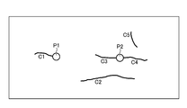
- FIG. 12 is a damage diagram including information on cracks.
- the damage diagram shown in FIG. 12 shows cracks C1 to C5 and P-con traces P1 and P2.
- crack C1 is a sinking crack generated in P-con trace P1
- cracks C4 and C5 are It is a sinking crack generated in the P-con trace P2.
- the damage diagram is represented by a drawing pattern by polylines along each crack C1 to C5, and can be used as CAD data.
- FIG. 13 is a chart showing an example of the damage quantity table included in the damage detection result, and corresponds to the damage chart shown in FIG.
- the damage quantity table shown in FIG. 13 has items of damage identification information (ID: identification), damage type, size (width), size (length), and size (area), and each item corresponds to each damage. Information to be done is described.
- each crack C1 to C5 are quantified, and this information is described in association with the damage ID in the damage quantity table.
- the first trained model 21A shown in FIG. 5 outputs each damaged area as a damage detection result 27A when the image 13 obtained by photographing the structure is input, but the damage detection result 27A is erroneously detected or failed. It may be detected accurately.
- the damaged area is classified in pixel units or in units of a group of several pixels, so it may lack accuracy. Further, it may be better to connect the cracks detected as two cracks as one crack. This is because it can be inferred that cracks are connected inside the concrete.
- the CPU 20 performs an edit instruction reception process for receiving an edit instruction for the damage detection result through an operation with the operation unit 18 (for example, a mouse) operated by the user, and edits the damage detection result according to the received edit instruction. Perform processing.
- the operation unit 18 for example, a mouse
- the damage detection result in the case of linear damage (cracking), in the case of a crack in which the end points of the polylines along the crack are close to each other, editing in which the end points are connected can be considered.
- the distance between the end points of the cracked polyline is measured after the damage detection process, and if the measured distance is less than the threshold value, the end points may be automatically connected or automatically according to the user's instruction. You may connect with.
- the threshold value may be a default value or may be user-configurable.
- a threshold value for the length and width of the crack may be set, and damage detection results smaller than the threshold value may be automatically deleted.
- the damage detection result may be deleted automatically after the damage detection process, or may be deleted according to the user's instruction.
- the threshold value may be a default value or may be user-configurable.
- FIG 14 and 15 are diagrams showing an editing example of the damage detection result, respectively.
- editing the damage detection result it is preferable to set the transparency of the color that fills the crack image to be high so that the image of the structure can be easily seen.
- FIG. 14 is a diagram showing a method of adding vertices to the polyline along the crack.
- the polyline is drawn by connecting a plurality of vertices along the crack (vertices indicated by squares in FIG. 14).
- FIG. 15 is a diagram showing a method of removing vertices from a polyline along a crack.
- the above editing functions include a function to select the entire poly line by clicking the line connecting the vertices and delete the entire poly line at once, and a function to manually add a new poly line to the crack detection omission point. Has.
- FIG. 16 is a flowchart showing an embodiment of the damage evaluation method according to the present invention.
- each step shown in FIG. 16 is performed by, for example, a processor configured by the CPU 20 of the damage evaluation device 10 shown in FIG.
- the processor acquires an image of the structure to be evaluated from the image acquisition unit 12, the image database 14, or the like (step S10).
- the first trained model 21A (FIG. 5) that functions as a damage detection processing unit detects damage (cracks) in the structure based on the image acquired in step S10 (step S12).
- the second trained model and 21B (FIG. 5), which function as the feature area detection process, detect the structure feature area (the area of the P-con trace) related to the construction of the structure based on the image acquired in step S10. (Step S14).
- the processor determines whether or not damage has been detected by the damage detection process performed in step S12 (step S16), and if damage has been detected (in the case of "Yes"), proceeds to step S18.
- step S18 from the damages (cracks) detected in step S12, specific damages (sinking cracks) related to the structural feature region are selected, and the process proceeds to step S20.
- step S20 it is determined whether or not the specific damage has been selected, and if it is determined that the specific damage has been selected (in the case of “Yes”), the processor outputs the information on the specific damage (step S22). ..
- the output of the specific damage information is performed, for example, by superimposing the damage image on the image, displaying the damage image alone on the display unit, or outputting the CAD data showing the damage diagram as a file. Further, it is preferable to specify the size (length) of the specific damage (sinking crack), color-code the sinking crack image according to the specified size, or output the line type differently.
- step S20 if it is determined in step S20 that the specific damage is not sorted (in the case of "No"), the damage (crack) detected in step S12 is output with crack information so that it can be identified as not a sinking crack. (Step S24). For example, a crack image is output with a color different from that of the sink crack or a line type. Note that step S24 may be omitted so that information other than specific damage (sinking and cracking) is not output.
- examples of P-con traces and joints are given as structural feature areas related to the construction of structures, but the present invention is not limited to this, and other structural feature areas such as joints may be detected. good.
- specific damage related to the structural feature area sinking cracks and crescent cracks were mentioned as examples, but water leaked from joints, joints, etc., or flowed out of the concrete member due to water leakage, etc., and water evaporated. Damage such as free lime on which the lime component appears on the surface is a specific damage related to the structural feature area (joint, joint area).
- the hardware that realizes the damage evaluation device according to the present invention can be configured by various processors.
- Various processors include CPUs (Central Processing Units) and FPGAs (Field Programmable Gate Arrays), which are general-purpose processors that execute programs and function as various processing units, and whose circuit configurations can be changed after manufacturing. It includes a dedicated electric circuit, which is a processor having a circuit configuration specially designed for executing a specific process such as a programmable logic device (PLD) and an ASIC (Application Specific Integrated Circuit).
- PLD programmable logic device
- ASIC Application Specific Integrated Circuit
- one processing unit may be composed of a plurality of FPGAs or a combination of a CPU and an FPGA.
- a plurality of processing units may be configured by one processor.
- one processor is configured by a combination of one or more CPUs and software, as represented by a computer such as a client or a server.
- a processor functions as a plurality of processing units.
- SoC System On Chip
- a processor that realizes the functions of the entire system including a plurality of processing units with one IC (Integrated Circuit) chip is used. be.
- the various processing units are configured by using one or more of the above-mentioned various processors as a hardware-like structure.
- the hardware structure of these various processors is, more specifically, an electric circuit (circuitry) in which circuit elements such as semiconductor elements are combined.
- the present invention also includes a damage evaluation program that causes the computer to function as a damage evaluation device according to the present invention by being installed in the computer, and a storage medium in which the damage evaluation program is recorded.
Landscapes
- Engineering & Computer Science (AREA)
- Physics & Mathematics (AREA)
- General Physics & Mathematics (AREA)
- Theoretical Computer Science (AREA)
- Quality & Reliability (AREA)
- Computer Vision & Pattern Recognition (AREA)
- Multimedia (AREA)
- Geometry (AREA)
- Investigating Materials By The Use Of Optical Means Adapted For Particular Applications (AREA)
- Image Analysis (AREA)
Priority Applications (4)
| Application Number | Priority Date | Filing Date | Title |
|---|---|---|---|
| JP2022519931A JP7429774B2 (ja) | 2020-05-07 | 2021-04-26 | 損傷評価装置、方法及びプログラム |
| EP21800080.0A EP4148663A4 (en) | 2020-05-07 | 2021-04-26 | Damage evaluating device, method, and program |
| CN202180029334.XA CN115443407B (zh) | 2020-05-07 | 2021-04-26 | 损伤评价装置、方法及记录介质 |
| US18/046,804 US20230113537A1 (en) | 2020-05-07 | 2022-10-14 | Damage evaluation device, method, and program |
Applications Claiming Priority (2)
| Application Number | Priority Date | Filing Date | Title |
|---|---|---|---|
| JP2020081971 | 2020-05-07 | ||
| JP2020-081971 | 2020-05-07 |
Related Child Applications (1)
| Application Number | Title | Priority Date | Filing Date |
|---|---|---|---|
| US18/046,804 Continuation US20230113537A1 (en) | 2020-05-07 | 2022-10-14 | Damage evaluation device, method, and program |
Publications (1)
| Publication Number | Publication Date |
|---|---|
| WO2021225084A1 true WO2021225084A1 (ja) | 2021-11-11 |
Family
ID=78467958
Family Applications (1)
| Application Number | Title | Priority Date | Filing Date |
|---|---|---|---|
| PCT/JP2021/016627 Ceased WO2021225084A1 (ja) | 2020-05-07 | 2021-04-26 | 損傷評価装置、方法及びプログラム |
Country Status (5)
| Country | Link |
|---|---|
| US (1) | US20230113537A1 (https=) |
| EP (1) | EP4148663A4 (https=) |
| JP (1) | JP7429774B2 (https=) |
| CN (1) | CN115443407B (https=) |
| WO (1) | WO2021225084A1 (https=) |
Cited By (2)
| Publication number | Priority date | Publication date | Assignee | Title |
|---|---|---|---|---|
| JP2024121765A (ja) * | 2023-02-27 | 2024-09-06 | コーマッパー カンパニー リミテッド | 構造物の安全診断のための構造物状態の分析方法及び装置 |
| WO2024219359A1 (ja) * | 2023-04-21 | 2024-10-24 | キヤノン株式会社 | 情報処理装置および情報処理方法 |
Families Citing this family (5)
| Publication number | Priority date | Publication date | Assignee | Title |
|---|---|---|---|---|
| KR102332940B1 (ko) * | 2021-06-07 | 2021-12-01 | (주)한스타일엔지니어링 | 안전 진단 대상 건축물에서의 균열선 길이 연산 방법 및 안전 진단 대상 건축물에서의 균열선 길이 연산 방법을 실행시키는 프로그램이 설치된 작업자 단말기 |
| US20230409780A1 (en) * | 2022-06-21 | 2023-12-21 | The Boeing Company | Method and System for Determining Ply-by-Ply Damage in a Composite Structure |
| CN116363464B (zh) * | 2023-03-31 | 2026-04-14 | 阿波罗智联(北京)科技有限公司 | 模型性能信息生成方法、装置及电子设备 |
| KR102895143B1 (ko) * | 2024-06-24 | 2025-12-04 | 엘림 주식회사 | 딥러닝을 이용한 시설물 결함 유형에 따른 측정방법 |
| CN120105030B (zh) * | 2025-05-12 | 2025-09-05 | 天津大学 | 路堤裂缝的评估方法及装置 |
Citations (12)
| Publication number | Priority date | Publication date | Assignee | Title |
|---|---|---|---|---|
| JP2005043324A (ja) * | 2003-07-25 | 2005-02-17 | Matsushita Electric Ind Co Ltd | 路面損傷状態点検方法及び路面損傷位置の特定方法 |
| JP2012225889A (ja) * | 2011-04-22 | 2012-11-15 | Taiheiyo Consultant:Kk | コンクリート構造物の劣化診断用画像表示システム |
| JP2015106238A (ja) * | 2013-11-29 | 2015-06-08 | 公益財団法人鉄道総合技術研究所 | コンクリート壁面画像から目地を検出する方法 |
| JP2015105905A (ja) | 2013-12-02 | 2015-06-08 | 公益財団法人鉄道総合技術研究所 | 変状の時系列管理に用いるトンネル覆工面画像の補正方法 |
| WO2016013133A1 (ja) * | 2014-07-25 | 2016-01-28 | 西日本高速道路エンジニアリング四国株式会社 | トンネル覆工面調査システムおよびトンネル覆工面調査システムに用いる車両 |
| JP2016121953A (ja) * | 2014-12-25 | 2016-07-07 | 西日本高速道路エンジニアリング四国株式会社 | トンネル覆工面画像のひび割れ領域抽出のための画像処理方法 |
| JP2016142601A (ja) * | 2015-01-30 | 2016-08-08 | 前田建設工業株式会社 | 施工品質評価プログラム、施工品質評価方法及び施工品質評価装置 |
| WO2017126367A1 (ja) * | 2016-01-22 | 2017-07-27 | 富士フイルム株式会社 | ひび割れ情報編集装置、ひび割れ情報編集方法およびひび割れ情報編集プログラム |
| WO2019009214A1 (ja) * | 2017-07-07 | 2019-01-10 | キヤノン株式会社 | 画像から変状を検知する画像処理装置、画像処理方法及びプログラム |
| KR20190066789A (ko) * | 2017-12-06 | 2019-06-14 | 서울시립대학교 산학협력단 | 딥러닝을 이용한 영상 기반 콘크리트 균열 탐지 시스템 |
| JP2019194562A (ja) * | 2018-04-26 | 2019-11-07 | キヤノン株式会社 | 情報処理装置、情報処理方法及びプログラム |
| JP2020038227A (ja) | 2016-06-14 | 2020-03-12 | 富士フイルム株式会社 | 画像処理方法、画像処理装置、及び画像処理プログラム |
Family Cites Families (8)
| Publication number | Priority date | Publication date | Assignee | Title |
|---|---|---|---|---|
| US4958306A (en) * | 1988-01-06 | 1990-09-18 | Pacific Northwest Research & Development, Inc. | Pavement inspection apparatus |
| JP2003035528A (ja) * | 2001-07-19 | 2003-02-07 | Ohbayashi Corp | ひび割れ画像計測による構造物の損傷度評価システム及び方法 |
| CN108027301B (zh) * | 2015-09-10 | 2019-07-19 | 富士胶片株式会社 | 损伤信息提取装置、损伤信息提取方法及损伤信息提取程序 |
| EP3596449A4 (en) * | 2017-03-14 | 2021-01-06 | University of Manitoba | DETECTION OF STRUCTURAL DEFECTS USING MACHINE LEARNING ALGORITHMS |
| JP6764842B2 (ja) * | 2017-09-22 | 2020-10-07 | エヌ・ティ・ティ・コムウェア株式会社 | 情報処理装置、情報処理システム、情報処理方法、及び情報処理プログラム |
| JP6516384B2 (ja) * | 2017-09-22 | 2019-05-22 | エヌ・ティ・ティ・コムウェア株式会社 | 情報処理装置、情報処理システム、情報処理方法、及び情報処理プログラム |
| WO2019163329A1 (ja) * | 2018-02-21 | 2019-08-29 | 富士フイルム株式会社 | 画像処理装置及び画像処理方法 |
| CN110378252A (zh) * | 2019-06-28 | 2019-10-25 | 浙江大学 | 一种基于深度迁移学习的混凝土裂缝识别方法 |
-
2021
- 2021-04-26 CN CN202180029334.XA patent/CN115443407B/zh active Active
- 2021-04-26 EP EP21800080.0A patent/EP4148663A4/en active Pending
- 2021-04-26 WO PCT/JP2021/016627 patent/WO2021225084A1/ja not_active Ceased
- 2021-04-26 JP JP2022519931A patent/JP7429774B2/ja active Active
-
2022
- 2022-10-14 US US18/046,804 patent/US20230113537A1/en active Pending
Patent Citations (12)
| Publication number | Priority date | Publication date | Assignee | Title |
|---|---|---|---|---|
| JP2005043324A (ja) * | 2003-07-25 | 2005-02-17 | Matsushita Electric Ind Co Ltd | 路面損傷状態点検方法及び路面損傷位置の特定方法 |
| JP2012225889A (ja) * | 2011-04-22 | 2012-11-15 | Taiheiyo Consultant:Kk | コンクリート構造物の劣化診断用画像表示システム |
| JP2015106238A (ja) * | 2013-11-29 | 2015-06-08 | 公益財団法人鉄道総合技術研究所 | コンクリート壁面画像から目地を検出する方法 |
| JP2015105905A (ja) | 2013-12-02 | 2015-06-08 | 公益財団法人鉄道総合技術研究所 | 変状の時系列管理に用いるトンネル覆工面画像の補正方法 |
| WO2016013133A1 (ja) * | 2014-07-25 | 2016-01-28 | 西日本高速道路エンジニアリング四国株式会社 | トンネル覆工面調査システムおよびトンネル覆工面調査システムに用いる車両 |
| JP2016121953A (ja) * | 2014-12-25 | 2016-07-07 | 西日本高速道路エンジニアリング四国株式会社 | トンネル覆工面画像のひび割れ領域抽出のための画像処理方法 |
| JP2016142601A (ja) * | 2015-01-30 | 2016-08-08 | 前田建設工業株式会社 | 施工品質評価プログラム、施工品質評価方法及び施工品質評価装置 |
| WO2017126367A1 (ja) * | 2016-01-22 | 2017-07-27 | 富士フイルム株式会社 | ひび割れ情報編集装置、ひび割れ情報編集方法およびひび割れ情報編集プログラム |
| JP2020038227A (ja) | 2016-06-14 | 2020-03-12 | 富士フイルム株式会社 | 画像処理方法、画像処理装置、及び画像処理プログラム |
| WO2019009214A1 (ja) * | 2017-07-07 | 2019-01-10 | キヤノン株式会社 | 画像から変状を検知する画像処理装置、画像処理方法及びプログラム |
| KR20190066789A (ko) * | 2017-12-06 | 2019-06-14 | 서울시립대학교 산학협력단 | 딥러닝을 이용한 영상 기반 콘크리트 균열 탐지 시스템 |
| JP2019194562A (ja) * | 2018-04-26 | 2019-11-07 | キヤノン株式会社 | 情報処理装置、情報処理方法及びプログラム |
Non-Patent Citations (2)
| Title |
|---|
| "Guide for Quality Assurance of Concrete Structure (draft", December 2015, TOHOKU REGIONAL DEVELOPMENT BUREAU, pages: 17 - 20 |
| See also references of EP4148663A4 |
Cited By (2)
| Publication number | Priority date | Publication date | Assignee | Title |
|---|---|---|---|---|
| JP2024121765A (ja) * | 2023-02-27 | 2024-09-06 | コーマッパー カンパニー リミテッド | 構造物の安全診断のための構造物状態の分析方法及び装置 |
| WO2024219359A1 (ja) * | 2023-04-21 | 2024-10-24 | キヤノン株式会社 | 情報処理装置および情報処理方法 |
Also Published As
| Publication number | Publication date |
|---|---|
| US20230113537A1 (en) | 2023-04-13 |
| EP4148663A4 (en) | 2023-10-25 |
| EP4148663A1 (en) | 2023-03-15 |
| CN115443407A (zh) | 2022-12-06 |
| JP7429774B2 (ja) | 2024-02-08 |
| CN115443407B (zh) | 2025-12-02 |
| JPWO2021225084A1 (https=) | 2021-11-11 |
Similar Documents
| Publication | Publication Date | Title |
|---|---|---|
| JP7429774B2 (ja) | 損傷評価装置、方法及びプログラム | |
| US12209972B2 (en) | Inspection support device, inspection support method, and inspection support program | |
| JP7102569B2 (ja) | 損傷情報処理装置、損傷情報処理方法、及び損傷情報処理プログラム | |
| US20230080316A1 (en) | Damage diagram creation method, damage diagram creation device, damage diagram creation system, and recording medium | |
| JP7146013B2 (ja) | サーバ装置、画像処理方法、及びプログラム | |
| JP7170023B2 (ja) | 損傷データ編集装置、損傷データ編集方法、プログラム、およびシステム | |
| JP7385942B2 (ja) | コンテキストアウェアな意味的コンピュータ視覚技術を使用して公共基幹施設の異常を検出するシステム及び方法 | |
| US11423511B2 (en) | Image composition method, image composition device, and recording medium | |
| US12106460B2 (en) | Information processing apparatus, information processing method, and non- transitory computer-readable storage medium | |
| CN111684234B (zh) | 修补长度的确定方法及修补长度的确定装置 | |
| JP7597310B2 (ja) | 画像表示装置、方法及びプログラム | |
| JP6894361B2 (ja) | コンクリート表面上のひび割れ方向特定方法、ひび割れ方向特定装置、ひび割れ方向特定システム及びプログラム | |
| Wang et al. | Automatic quality inspection of rebar spacing using vision-based deep learning with RGBD camera | |
| JP7413383B2 (ja) | 情報表示装置、方法及びプログラム | |
| JP7326446B2 (ja) | 画像表示装置、方法及びプログラム | |
| JP7564671B2 (ja) | 情報処理装置、制御方法、及び、プログラム | |
| JP2004021578A (ja) | 画像処理方法 | |
| Ghahremani et al. | Automated 3d image-based section loss detection for finite element model updating | |
| JP4963824B2 (ja) | 変化領域抽出装置及び変化領域抽出方法 | |
| JP7499210B2 (ja) | ひび割れ検出方法とひび割れ検出装置、及びプログラム | |
| CN110570385B (zh) | 基于遥感解译的边界套合方法、系统、存储介质及设备 | |
| JP2024162145A (ja) | ひび割れ検出方法とひび割れ検出装置、及びプログラム |
Legal Events
| Date | Code | Title | Description |
|---|---|---|---|
| 121 | Ep: the epo has been informed by wipo that ep was designated in this application |
Ref document number: 21800080 Country of ref document: EP Kind code of ref document: A1 |
|
| ENP | Entry into the national phase |
Ref document number: 2022519931 Country of ref document: JP Kind code of ref document: A |
|
| NENP | Non-entry into the national phase |
Ref country code: DE |
|
| ENP | Entry into the national phase |
Ref document number: 2021800080 Country of ref document: EP Effective date: 20221207 |