WO2021220916A1 - Stator ayant une structure de bobine d'enroulement réparti, et moteur électrique à courant alternatif triphasé comprenant ledit stator - Google Patents
Stator ayant une structure de bobine d'enroulement réparti, et moteur électrique à courant alternatif triphasé comprenant ledit stator Download PDFInfo
- Publication number
- WO2021220916A1 WO2021220916A1 PCT/JP2021/016210 JP2021016210W WO2021220916A1 WO 2021220916 A1 WO2021220916 A1 WO 2021220916A1 JP 2021016210 W JP2021016210 W JP 2021016210W WO 2021220916 A1 WO2021220916 A1 WO 2021220916A1
- Authority
- WO
- WIPO (PCT)
- Prior art keywords
- slot
- coil
- winding
- slots
- phase
- Prior art date
Links
Images


Classifications
-
- H—ELECTRICITY
- H02—GENERATION; CONVERSION OR DISTRIBUTION OF ELECTRIC POWER
- H02K—DYNAMO-ELECTRIC MACHINES
- H02K3/00—Details of windings
- H02K3/04—Windings characterised by the conductor shape, form or construction, e.g. with bar conductors
- H02K3/28—Layout of windings or of connections between windings
-
- H—ELECTRICITY
- H02—GENERATION; CONVERSION OR DISTRIBUTION OF ELECTRIC POWER
- H02K—DYNAMO-ELECTRIC MACHINES
- H02K1/00—Details of the magnetic circuit
- H02K1/06—Details of the magnetic circuit characterised by the shape, form or construction
- H02K1/12—Stationary parts of the magnetic circuit
- H02K1/16—Stator cores with slots for windings
-
- H—ELECTRICITY
- H02—GENERATION; CONVERSION OR DISTRIBUTION OF ELECTRIC POWER
- H02K—DYNAMO-ELECTRIC MACHINES
- H02K21/00—Synchronous motors having permanent magnets; Synchronous generators having permanent magnets
- H02K21/12—Synchronous motors having permanent magnets; Synchronous generators having permanent magnets with stationary armatures and rotating magnets
- H02K21/14—Synchronous motors having permanent magnets; Synchronous generators having permanent magnets with stationary armatures and rotating magnets with magnets rotating within the armatures
-
- H—ELECTRICITY
- H02—GENERATION; CONVERSION OR DISTRIBUTION OF ELECTRIC POWER
- H02K—DYNAMO-ELECTRIC MACHINES
- H02K3/00—Details of windings
- H02K3/04—Windings characterised by the conductor shape, form or construction, e.g. with bar conductors
- H02K3/12—Windings characterised by the conductor shape, form or construction, e.g. with bar conductors arranged in slots
Definitions
- the present invention relates to a stator having a distributed winding coil structure and a three-phase AC motor including the stator.
- the number of poles and the number of slots can be selected so as to increase the number of poles and the least common multiple of the number of slots, and the value of the high-order distributed winding coefficient can be reduced. Can be reduced.
- lap winding is a winding method in which coils of the same pitch are lapped.
- the coil end (the end of the coil that is not housed in the stator) is small because the interference between the coils is small.
- the lap winding has an advantage that the winding arrangement can be performed without restriction in most of the three-phase AC motors having the number of poles and the number of slots.
- the number of poles specified from an even number and the number of slots specified from a multiple of 3 from arbitrary values. Therefore, it is also possible to select a slot number having a relatively small value with respect to the selected number of poles. Since the coil pitch of the coil of the motor is approximately the number of slots divided by the number of poles, the number of poles and the number of slots can be selected so that the coil pitch becomes small (for example, coil pitch 2 or 3). It is possible to shorten the total length of the motor and reduce the copper loss of the coil.
- all phases are divided into winding groups in which the number of continuous phase bands is C, and the coils belonging to each winding group.
- One of the coils is divided into two coils whose number of conductors is about half that of the other coils, and the divided coils are distributed to adjacent two-phase bands, and this divided coil is distributed to a parallel circuit.
- a three-phase armature winding is known (see, for example, Patent Document 2).
- a split-type armature is provided, and a single-layer lap-wound three-phase AC armature coil is mounted on the armature core so as not to straddle the split portion of the stator, and the adjacent armature coil is used.
- the connection order is changed so that a predetermined voltage vector is obtained at the connection portion between the armature coils of a predetermined phase.
- An armature winding of an electric motor characterized by providing a connecting wire for change is known (see, for example, Patent Document 3).
- a distributed winding is inserted into two slots having an annular shape and having a plurality of slots arranged on the inner circumference along the inner circumference and a pair of odd-pitch slots among the plurality of slots in the stator core.
- the stator core is divided in the circumferential direction at the position of the bottom of the slot, and each divided stator core component has two teeth, and the stator core is divided.
- a protrusion is formed on at least one of the facing surfaces that partition the slot at the position at a position closer to the center of the stator core than the position of the inner peripheral end of the coil, and the portion where the protrusion is formed.
- a stator of a rotary electric machine is known in which the width of the slot in the circumferential direction is narrower than the width of the coil (see, for example, Patent Document 4).
- N / (6P) is a reduced fraction whose denominator value is 4 or more, and N.
- N / (6P) is a reduced fraction whose denominator value is 4 or more, and N.
- N / (6P) is a reduced fraction whose denominator value is 4 or more, and N.
- N / (6P) is a reduced fraction whose denominator value is 4 or more, and N.
- any winding of a total of six phases of three phases and their opposite phases is arranged in two layers for each slot.
- the three-phase windings of U-phase, V-phase, and W-phase are rotationally symmetric with each other at a mechanical angle of ⁇ 120 degrees with respect to the winding arrangement of one layer.
- each phase of the winding of the first layer having the rotational symmetry is phase-inverted by 180 degrees at an electric angle, and the first layer is arranged so as to have a property.
- the windings are arranged so as to be offset by M slots, and the number of pole pairs P, the number of slots N, and the number of slot shifts M are the following relational expressions, 4/35 ⁇
- ⁇ 8/35 is satisfied see, for example, Patent Document 5).
- a rotor having a plurality of pairs of magnetic poles and a stator having a plurality of slots formed in the rotation axis direction of the rotor and arranged in the circumferential direction and arranged so as to face the rotor in the radial direction.
- coils wound with a predetermined number of turns are arranged in 2N slots per phase, and each coil is aligned with another coil connected in series in the direction of current.
- each of the two coils that share one side and are stacked in one central slot and do not share the slots of the two coils is different in that the slots are separated from the central slot by X.
- the two coils are arranged in a figure eight shape over three slots, and the set of the figure eight connecting coils is arranged in one phase in the slot of the stator.
- a three-phase AC electric motor is known in which each of the N sets is arranged at a position where they do not completely overlap each other and are connected in series (see, for example, Patent Document 6).
- the number of slots of the slots arranged in the circumferential direction is larger than 1.5 times the number of poles, and the value obtained by dividing the number of slots by the number of poles is a fractional slot type three.
- the stator of the phase AC motor includes a plurality of sets of coils in which each of two or three coils having the same coil pitch is arranged in the slots with a shift of one slot pitch by one slot, and the stator of the plurality of sets of coils is provided. Each of the sets is arranged 60 degrees apart from each other in the circumferential direction.
- the three-phase AC motor includes the stator and a rotor arranged so as to face the stator in the radial direction.
- a stator having a distributed winding coil structure capable of automatic winding can be realized. Can be done.
- FIG. 1 is a cross-sectional view (No. 1) for explaining the symmetry of the winding arrangement of the stator in the three-phase AC motor having 10 poles and 36 slots shown in FIG.
- No. 1 is a cross-sectional view (No. 1) for explaining the symmetry of the winding arrangement of the stator in the three-phase AC motor having 10 poles and 36 slots shown in FIG.
- U-phase winding of the stator shown in FIG. It is sectional drawing explaining the symmetry of the V-phase winding of the stator shown in FIG. It is sectional drawing explaining the symmetry of the W phase winding of the stator shown in FIG.
- FIG. 1 is a cross-sectional view (No. 1) for explaining the symmetry of the winding arrangement of the stator in the three-phase AC motor having 10 poles and 36 slots shown in FIG.
- U-phase winding of the stator shown in FIG. It is sectional drawing explaining the symmetry of the V-phase winding of the stator shown in FIG.
- FIG. 2 is a cross-sectional view (No. 2) for explaining the symmetry of the winding arrangement of the stator in the three-phase AC motor of 10 poles and 36 slots shown in FIG. 1, and shows the winding arrangement of the ⁇ U phase band.
- FIG. 2 is a cross-sectional view (No. 2) for explaining the symmetry of the winding arrangement of the stator in the three-phase AC motor of 10 poles and 36 slots shown in FIG. 1, and shows the winding arrangement of the + V phase band.
- FIG. 2 is a cross-sectional view (No. 2) for explaining the symmetry of the winding arrangement of the stator in the three-phase AC motor of 10 poles and 36 slots shown in FIG. 1, and shows the winding arrangement of the ⁇ W phase band.
- FIG. 2 is a cross-sectional view (No. 2) for explaining the symmetry of the winding arrangement of the stator in the three-phase AC motor of 10 poles and 36 slots shown in FIG. 1, and shows the winding arrangement of the ⁇ W phase band.
- FIG. 2 is a cross-sectional view (No. 2) for explaining the symmetry of the winding arrangement of the stator in the three-phase AC motor of 10 poles and 36 slots shown in FIG. 1, and shows the winding arrangement of the + U phase band.
- FIG. 2 is a cross-sectional view (No. 2) for explaining the symmetry of the winding arrangement of the stator in the three-phase AC motor of 10 poles and 36 slots shown in FIG. 1, and shows the winding arrangement of the ⁇ V phase band.
- FIG. 2 is a cross-sectional view (No. 2) for explaining the symmetry of the winding arrangement of the stator in the three-phase AC motor of 10 poles and 36 slots shown in FIG. 1, and shows the winding arrangement of the + W phase band.
- FIG. 8A It is sectional drawing which shows the winding arrangement of the-U phase band shown in FIG. 8A. It is sectional drawing of the stator in the three-phase AC motor of 10 poles and 24 slots according to the embodiment of this disclosure. It is a developed sectional view of the stator shown in FIG. It is a developed sectional view explaining each coil arrangement in the stator shown in FIG. It is sectional drawing of the stator in the three-phase AC motor of 14 poles and 24 slots according to the embodiment of this disclosure. It is a developed sectional view of the stator shown in FIG. It is a developed sectional view explaining each coil arrangement in the stator shown in FIG. FIG.
- FIG. 5 is a cross-sectional view of a stator in a 22-pole 48-slot three-phase AC motor according to an embodiment of the present disclosure. It is a developed sectional view of the stator shown in FIG. FIG. 5 is a cross-sectional view of a stator in a 22-pole 72-slot three-phase AC motor according to an embodiment of the present disclosure. It is a developed sectional view of the stator shown in FIG. It is sectional drawing of the stator in the three-phase AC motor of 34 poles 108 slots according to the embodiment of this disclosure. It is a developed sectional view of the slot identification number 1 to 54 of the stator shown in FIG. It is a developed sectional view of the slot identification number 55 to 108 of the stator shown in FIG.
- FIG. 3 It is a figure which illustrates the appearance of the three-phase AC motor provided with the stator according to the embodiment of this disclosure. It is a figure exemplifying a coil and a three-phase AC electric motor provided with this, and illustrates the coil in the stator shown in FIG. 3, FIG. 12, FIG. 15, FIG. 17, FIG. 19, FIG. 21, FIG. 22, and FIG. 25. do. It is a figure exemplifying a coil and a three-phase AC motor provided with the coil, and illustrates the positional relationship of a stator and a rotor of a three-phase AC motor. It is a developed sectional view explaining the definition of the coil group in the stator according to the embodiment of this disclosure.
- stator having a distributed winding lap coil structure and a three-phase AC motor equipped with the stator will be described.
- similar members are designated by the same reference numerals.
- scales of these drawings have been changed as appropriate for ease of understanding. Further, the form shown in the drawings is an example for carrying out, and is not limited to the illustrated form.
- a wire rod such as a copper wire through which an electric current flows or a bundle of wire rods is referred to as a "winding”.
- a coil in which a closed ring is formed by using a wire and connected in the same shape and overlapped in a bundle is called a "coil”.
- the coil is divided into a portion accommodated in the slot of the stator and a portion not accommodated. When each is clearly separated, the former is referred to as “winding” and the latter is referred to as "coil end”. Further, the number of slots across which the coils housed in the stator slots straddle is referred to as "coil pitch”.
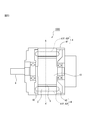
- FIG. 24A is a diagram illustrating a coil and a three-phase AC motor including the coil, and is a stator shown in FIGS. 3, 12, 15, 17, 19, 19, 21, 22, and 25. Illustrate the coil in.
- FIG. 24B is a diagram illustrating a coil and a three-phase AC motor including the coil, and illustrates the positional relationship between a stator and a rotor of the three-phase AC motor.
- the coil 4 includes a positive winding (+ winding) 41P and a negative winding (-winding) 41N accommodated in the slot, and a coil end 42 not accommodated in the slot.
- the rotor 10 is provided so as to face the stator 1 in which the coil (winding) 4 is housed in the slot 2 in the radial direction.
- the rotor 10 is provided with a magnetic pole 21 of a magnet.
- the coil pitch is about 180 degrees in electrical angle per pole, and the mechanical angle.
- a coil pitch of about "180 degrees ⁇ number of poles" is required in terms of conversion.
- the coil pitch is "the integer part in decimal notation which is the quotient of the number of slots ⁇ the value obtained by the number of poles" or "the number of slots ⁇ the value obtained by the number of poles". It is specified by one of the integer part + 1 in decimal notation, which is the quotient of.
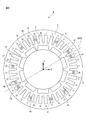
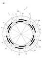
- FIG. 1 is a cross-sectional view of a stator in a 10-pole 36-slot three-phase AC motor according to the embodiment of the present disclosure.
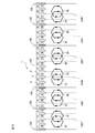
- FIG. 2 is a developed cross-sectional view of the stator shown in FIG.
- FIG. 3 is a developed cross-sectional view illustrating each coil arrangement in the stator shown in FIG. In FIGS. 1 to 3, the magnetic poles of the rotor are not shown.
- U, V, and W represent each phase of three-phase alternating current, and each has a phase difference of ⁇ 120 degrees in electrical angle.
- "+" and "-" indicate the direction of the electric current, and the phase difference thereof is 180 degrees in terms of electric angle.
- each slot 2 provided in the core 3 of the stator 1 two of each of a total of six phase bands of + U, ⁇ U, + V, ⁇ V, + W, and ⁇ W phases are arranged.
- the same number of wires such as copper wires through which current flows are inserted in each arrangement.
- the stator 1 is originally cylindrical, but here, in order to make the explanation easier to understand, a developed cross-sectional view of the cylindrical stator 1 will also be described.
- the number of slots of the slots 2 arranged in the circumferential direction is larger than 1.5 times the number of poles, and the value obtained by dividing the number of slots by the number of poles is an irreducible fraction.
- It is a fractional slot type three-phase AC motor, and includes a stator 1 and a rotor arranged so as to face the stator 1 in the radial direction.
- the number of pole pairs of the rotor of the three-phase AC motor is P
- the number of poles is 2P.
- the number of slots into which the winding of the stator 1 is inserted is 6N
- the value obtained by dividing the number of slots 6N by the number of poles 2P represents the slot pitch of the coil 4.
- a three-phase AC motor in which the value obtained by dividing the number of slots 6N by the number of poles 2P is larger than 1.5 has a coil slot pitch of 2 or more, and requires a distributed winding (overlapping winding) coil structure.
- each of a plurality of coils having the same coil pitch shape is displaced by one slot due to lap winding, and three coils are lap-wound and arranged in the slots.
- the coils that are wound one slot at a time in this way are hereinafter referred to as "the number of continuous coils".
- the number of continuous coils is 3 in all the lap winding sets.
- the stator 1 includes a plurality of sets of coils in which two or three coils 4 having the same coil pitch are arranged in slots with a shift of one slot pitch. Further, the plurality of sets of coils are arranged in six coil groups for all slots, and more specifically, each coil group is arranged at a position shifted by 60 degrees.
- FIG. 25 is a developed cross-sectional view illustrating the definition of the coil group in the stator according to the embodiment of the present disclosure.
- the term "set (of coils)” means a group consisting of a plurality of (three in the example shown in FIG. 25) coils having the same coil pitch shape by lap winding.
- the "coil group” means a group each of which is composed of a plurality of sets of coils and is arranged at positions shifted by 60 degrees.
- each of the six coil groups will be referred to as a first coil group, a second coil group, a third coil group, a fourth coil group, a fifth coil group, and a sixth coil group.
- each coil is formed to have the same coil pitch, and is arranged in a slot by lap winding with a shift of one slot pitch.
- the quotient 3 which is an integer part in the decimal notation of the value obtained by dividing the number of slots 36 by the number of poles 10 is fixed. It becomes the coil pitch of the child. Further, since the number of slots of the stator 1 is 36, each of the U-phase, V-phase, and W-phase coils is evenly divided into six coil groups over the entire 36 slots, and lap winding is performed in each group. It will be possible. As shown in FIG. 2, the number of continuous coils for lap winding of 10 poles and 36 slots is 3.
- each set the three coils have a coil pitch of 3, and one set of lap windings is formed in 6 slots, and the sets are arranged apart from each other.
- Each of these three coils is configured as a U-phase winding, which is a first-phase winding, a V-phase winding, which is a second-phase winding, and a W-phase winding, which is a third-phase winding. Specifically, it is as follows.
- each of the three coils U1, W1, and V1 having the same coil pitch is arranged in slots offset by one slot pitch. More specifically, in the coil U1, the directions of the currents flowing in the winding arranged in the slot of the slot identification number 1 and the winding arranged in the slot of the slot identification number 4 with a deviation of 3 coil pitches are opposite to each other. It is formed in this way and placed in the slots of slot identification numbers 1 and 4.
- the coil W1 is arranged in a slot shifted by one slot from the coil V1. That is, the coil W1 is formed so that the directions of the currents flowing in the winding arranged in the slot of the slot identification number 2 and the winding arranged in the slot of the slot identification number 5 are opposite to each other.
- the coil V1 is arranged in a slot shifted by one slot from the coil W1. That is, the coil V1 is formed so that the directions of the currents flowing in the winding arranged in the slot of the slot identification number 3 and the winding arranged in the slot of the slot identification number 6 are opposite to each other. It is placed in the slots of identification numbers 3 and 6.
- each of the three coils V2, U2, and W2 having the same coil pitch is arranged in slots offset by one slot pitch.
- the second coil group is arranged at a position deviated by 60 degrees in the circumferential direction (clockwise in the example shown in FIG. 1) from the first coil group. More specifically, the coil V2 is formed so that the directions of the currents flowing in the winding arranged in the slot of slot identification number 7 and the winding arranged in the slot of slot identification number 10 are opposite to each other. , Placed in slots with slot identification numbers 7 and 10.
- the coil U2 is arranged in a slot shifted by one slot from the coil V2.
- the coil U2 is formed so that the directions of the currents flowing in the winding arranged in the slot of the slot identification number 8 and the winding arranged in the slot of the slot identification number 11 are opposite to each other. It is arranged in the slots of identification numbers 8 and 11.
- the coil W2 is arranged in a slot shifted by one slot from the coil U2. That is, the coil W2 is formed so that the directions of the currents flowing in the winding arranged in the slot of the slot identification number 9 and the winding arranged in the slot of the slot identification number 12 are opposite to each other. It is arranged in the slots of identification numbers 9 and 12.
- each of the three coils W3, V3, and U3 having the same coil pitch is arranged in slots offset by one slot pitch. Further, the third coil group is arranged at a position deviated by 60 degrees from the second coil group in the same direction as the circumferential direction (that is, clockwise). More specifically, the coil W3 is formed so that the directions of the currents flowing in the winding arranged in the slot of the slot identification number 13 and the winding arranged in the slot of the slot identification number 16 are opposite to each other. , Are placed in the slots of slot identification numbers 13 and 16. The coil V3 is arranged in a slot shifted by one slot from the coil W3.
- the coil V3 is formed so that the directions of the currents flowing in the winding arranged in the slot of the slot identification number 14 and the winding arranged in the slot of the slot identification number 17 are opposite to each other. It is arranged in the slots of identification numbers 14 and 17.
- the coil U3 is arranged in a slot shifted by one slot from the coil V3. That is, the coil U3 is formed so that the directions of the currents flowing in the winding arranged in the slot of the slot identification number 15 and the winding arranged in the slot of the slot identification number 18 are opposite to each other. It is placed in the slots of identification numbers 15 and 18.
- each of the three coils U4, W4, and V4 having the same coil pitch is arranged in slots offset by one slot pitch. Further, the fourth coil group is arranged at a position deviated by 60 degrees from the third coil group in the same direction as the circumferential direction (that is, clockwise). More specifically, the coil U4 is formed so that the directions of the currents flowing in the winding arranged in the slot of slot identification number 19 and the winding arranged in the slot of slot identification number 22 are opposite to each other. , Placed in slots of slot identification numbers 19 and 22. The coil W4 is arranged in a slot shifted by one slot from the coil U4.
- the coil W4 is formed so that the directions of the currents flowing in the winding arranged in the slot of the slot identification number 20 and the winding arranged in the slot of the slot identification number 23 are opposite to each other. It is arranged in the slots of identification numbers 20 and 23.
- the coil V4 is arranged in a slot shifted by one slot from the coil W4. That is, the coil V4 is formed so that the directions of the currents flowing in the winding arranged in the slot of the slot identification number 21 and the winding arranged in the slot of the slot identification number 24 are opposite to each other. It is arranged in the slots of identification numbers 21 and 24.
- each of the three coils V5, U5, and W5 having the same coil pitch is arranged in slots offset by one slot pitch. Further, the fifth coil group is arranged at a position deviated by 60 degrees from the fourth coil group in the same direction as the circumferential direction (that is, clockwise). More specifically, the coil V5 is formed so that the directions of the currents flowing in the winding arranged in the slot of slot identification number 25 and the winding arranged in the slot of slot identification number 28 are opposite to each other. , Placed in slots of slot identification numbers 25 and 28. The coil U5 is arranged in a slot shifted by one slot from the coil V5.
- the coil U5 is formed so that the directions of the currents flowing in the winding arranged in the slot of the slot identification number 26 and the winding arranged in the slot of the slot identification number 29 are opposite to each other. It is arranged in the slots of identification numbers 26 and 29.
- the coil W5 is arranged in a slot shifted by one slot from the coil U5. That is, the coil W5 is formed so that the directions of the currents flowing in the winding arranged in the slot of the slot identification number 27 and the winding arranged in the slot of the slot identification number 30 are opposite to each other. It is arranged in the slots of identification numbers 27 and 30.
- each of the three coils W6, V6, and U6 having the same coil pitch is arranged in slots offset by one slot pitch. Further, the sixth coil group is arranged at a position deviated by 60 degrees from the fifth coil group in the same direction as the circumferential direction (that is, clockwise). More specifically, the coil W6 is formed so that the directions of the currents flowing in the winding arranged in the slot of the slot identification number 31 and the winding arranged in the slot of the slot identification number 34 are opposite to each other. , Slot identification numbers 31 and 34. The coil V6 is arranged in a slot shifted by one slot from the coil W6.
- the coil V6 is formed so that the directions of the currents flowing in the winding arranged in the slot of the slot identification number 32 and the winding arranged in the slot of the slot identification number 35 are opposite to each other. It is arranged in the slots of identification numbers 32 and 35.
- the coil U6 is arranged in a slot that is one slot bitch offset from the coil V6. That is, the coil U6 is formed so that the directions of the currents flowing in the winding arranged in the slot of the slot identification number 33 and the winding arranged in the slot of the slot identification number 36 are opposite to each other. It is arranged in the slots of identification numbers 33 and 36.
- the coils U1, U2, U3, U4, U5, and U6 described above are connected by a crossover and are configured as a U-phase winding in the stator 1. Further, the coils V1, V2, V3, V4, V5, and V6 described above are connected by a crossover wire and are configured as a V-phase winding in the stator 1. Further, the coils W1, W2, W3, W4, W5, and W6 described above are connected by a crossover wire and are configured as a W-phase winding in the stator 1.
- the 10-pole 36-slot three-phase AC motor includes the above-mentioned stator 1 and rotors arranged radially opposite to the stator 1.
- stator slots of the subject of the present invention is limited to a multiple of 6.
- Form (III) When N / P> 2 (or the number of slots ⁇ the number of poles> 4), there is no method of lap winding in which one layer can be wound per slot. That is, the embodiment of the present disclosure is not applicable.
- N is a value obtained by dividing the number of slots 6N by 6, and is an integer. Further, P is an odd number of 5 or more.
- the value obtained by dividing the number of slots 36 by the number of poles 10 is 3.6, which corresponds to the case of the above-mentioned form (II).
- the coil pitch is 3
- the number of continuous coils is 3
- the number of continuous lap winding occupied slots is 6.
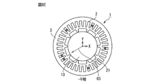
- FIG. 4 is a cross-sectional view illustrating the symmetry of the winding arrangement of the stator in the 10-pole 36-slot three-phase AC motor shown in FIG.
- FIG. 5 is a cross-sectional view illustrating the symmetry of the U-phase winding of the stator shown in FIG.
- FIG. 6 is a cross-sectional view illustrating the symmetry of the V-phase winding of the stator shown in FIG.
- FIG. 7 is a cross-sectional view illustrating the symmetry of the W-phase winding of the stator shown in FIG.
- the magnetic pole 21 of the rotor 10 is also shown.
- the stator of the 10-pole 36-slot three-phase AC motor shown in FIG. 1 in the first coil group U1, the second coil group U2, and the third coil group U3, as shown in FIGS. 4 and 5.
- the first-phase winding (U-phase winding) and the first-phase winding (U-phase winding) in the sixth coil group U6, the fifth coil group U5, and the fourth coil group U4 are stators. It is arranged line-symmetrically with respect to the first axis of symmetry 100U on the peripheral plane of 1. Further, as shown in FIGS. 4 and 6, the second coil group V2, the third coil group V3, and the second coil group V4 in the second coil group V2, the second coil group V4, and the first coil.
- the second phase winding (V phase winding) in the group V1, the sixth coil group V6, and the fifth coil group V5 is axisymmetric with respect to the second axis of symmetry 100V on the circumferential plane of the stator 1. Is placed in. Further, as shown in FIGS. 4 and 7, the third phase winding (W phase winding) and the second coil in the third coil group W3, the fourth coil group W4, and the fifth coil group W5.
- the third phase winding (W phase winding) in the group W2, the first coil group W1 and the sixth coil group W6 is axisymmetric with respect to the third axis of symmetry 100W on the circumferential plane of the stator 1. Is placed in.
- the first axis of symmetry 100U, the second axis of symmetry 100V, and the third axis of symmetry 100W are arranged so as to be offset from each other by 60 degrees.
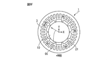
- FIG. 8A is a cross-sectional view (No. 2) for explaining the symmetry of the winding arrangement of the stator in the three-phase AC motor of 10 poles and 36 slots shown in FIG. show.
- FIG. 8B is a cross-sectional view (No. 2) for explaining the symmetry of the winding arrangement of the stator in the three-phase AC motor of 10 poles and 36 slots shown in FIG. 1, showing the winding arrangement of the + V phase band. ..
- FIG. 8C is a cross-sectional view (No. 2) for explaining the symmetry of the winding arrangement of the stator in the three-phase AC motor of 10 poles and 36 slots shown in FIG. show.
- FIG. 8D is a cross-sectional view (No.
- FIG. 8E is a cross-sectional view (No. 2) for explaining the symmetry of the winding arrangement of the stator in the three-phase AC motor of 10 poles and 36 slots shown in FIG. show.
- FIG. 8F is a cross-sectional view (No. 2) for explaining the symmetry of the winding arrangement of the stator in the three-phase AC motor of 10 poles and 36 slots shown in FIG. 1, and shows the winding arrangement of the + W phase band. .. In FIG.
- reference numeral 61 is a line symmetry axis of the ⁇ U phase band and indicates a vector indicating the arrangement direction.
- reference numeral 62 is a line symmetry axis of the + V phase band and indicates a vector indicating the arrangement direction.
- reference numeral 63 indicates a vector indicating the arrangement direction, which is the axis of line symmetry of the ⁇ W phase band.
- reference numeral 64 is a line symmetry axis of the + U phase band and indicates a vector indicating the arrangement direction.
- reference numeral 65 is a line symmetry axis of the ⁇ V phase band and indicates a vector indicating the arrangement direction.
- reference numeral 66 is a line symmetry axis of the + W phase band and indicates a vector indicating the arrangement direction.
- FIG. 9 is a cross-sectional view showing the winding arrangement of the ⁇ U phase band shown in FIG. 8A.
- the slot pitch to the adjacent winding may be 70 degrees for windings in the same phase band (-U phase band in the example shown in FIG. 9).
- the number of pole pairs is an odd number of 5 or more, the axis of line symmetry always exists. This is based on the following reasons.
- the winding arrangement When the winding arrangement is optimized so that the waveform of the induced voltage generated in the stator coil approaches a sine wave for each of the six phase bands of ⁇ U, ⁇ V, and ⁇ W, the winding of each phase band Are arranged so as to be evenly distributed and at a slot pitch close to the value of 360 ⁇ pole logarithm P, so that the windings are arranged so as to approach a regular P square (where P is pole logarithm).
- the regular P-side has P-fold rotational symmetry, and also has line symmetry about each vertex and a line perpendicular to the center of the opposite side of the vertex.
- FIG. 9 shows the arrangement of the windings of the ⁇ U phase among the 6 phase bands of ⁇ U, ⁇ V, and ⁇ W.
- the winding arrangement of is close to a regular pentagon.
- the slot pitch from one -U phase winding to the adjacent -U winding is preferably a mechanical angle of 72 degrees for one electrical angle cycle.
- the slot pitch of -U6 and -U1 is 10 degrees for one slot, -U1 and -U2, -U2 and -U3, -U3 and -U4, -U4 and -U5, and -U5 and -U6.
- the winding arrangement of each of the remaining five-phase bands also has no rotational symmetry, but has an axis of line symmetry.
- the line symmetry axis 100U for the -U phase and the + U phase the line symmetry axis 100V for the -V phase and the + V phase, and the -W phase and the + W phase.
- the line symmetry axis 100W of is coincided with the line that divides the coil group.
- the U-phase windings are arranged so as to have one axis that is line-symmetric, and the V-phase windings are arranged so that they have one axis that is line-symmetrical.
- the W-phase windings are arranged so as to have one axis that is axisymmetric. That is, the U-phase windings are arranged line-symmetrically with respect to the line-symmetry axis 100U, the V-phase windings are arranged line-symmetrically with respect to the line-symmetry axis 100V, and the W-phase windings are arranged line-symmetrically with respect to the line-symmetry axis 100W. Arranged line-symmetrically. This is a feature of a three-phase AC motor in which the pole logarithm P is an odd number and the value obtained by dividing the number of slots by the number of poles is a specified fraction.
- the number of continuous coils for lap winding is 2, and two of the three phases are assigned to two coils for lap winding, so that one set of lap winding has three phases. Becomes uneven. Therefore, a certain one-phase axisymmetric axis is positioned so as to divide the set of the remaining two-phase lap winding from the center, and intersects with the coil ends of the remaining two-phase coils.
- the number of continuous coils for lap winding is 3, and all three of the three phases are evenly allocated in each set of lap winding, so that the coil group that divides the slot evenly. The dividing line of is always coincident with the line symmetry axis of each phase.
- the axisymmetric axes 100U, 100V, and 100W of the windings of each phase coincide with the lines that divide the first to sixth coil groups. ..
- FIG. 10 is a cross-sectional view of a stator in a 10-pole 24-slot three-phase AC motor according to the embodiment of the present disclosure.
- FIG. 11 is a developed cross-sectional view of the stator shown in FIG.
- FIG. 12 is a developed cross-sectional view illustrating each coil arrangement in the stator shown in FIG. In FIGS. 10 to 12, the magnetic poles of the rotor are not shown.
- a three-phase AC motor with 10 poles and 24 slots satisfies the requirement that "the number of slots is greater than 1.5 times the number of poles" because the value obtained by dividing the number of slots 24 by the number of poles 10 is 2.4. Further, since 12/5, which is the value obtained by dividing the number of slots 24 by the number of poles 10, is an irreducible fraction, it can be said to be a fractional slot type.
- the 10-pole 24-slot three-phase AC motor corresponds to the case of the form (I), the coil pitch is 2, and the number of continuous coils is 2. Therefore, two coils having a coil pitch of 2 and one set are arranged over the four slots with the slot pitch shifted by one. Therefore, since the number of slots of the stator 1 is 24, each of the U-phase, V-phase, and W-phase coils is evenly divided into six coil groups over the entire 24 slots, and lap winding is performed in each group. It will be possible.
- Each of the two coils in each set of these lap windings is a U-phase winding which is a first-phase winding, a V-phase winding which is a second-phase winding, and a W-phase winding which is a third-phase winding. It is configured as any two of them.
- each of the two coils W1 and V1 having the same coil pitch are arranged in slots shifted by one slot pitch. More specifically, in the coil W1, the directions of the currents flowing in the winding arranged in the slot of the slot identification number 1 and the winding arranged in the slot of the slot identification number 3 with a deviation of 2 coil pitches are opposite to each other. It is formed in this way and placed in the slots of slot identification numbers 1 and 3.
- the coil V1 is arranged in a slot shifted by one slot from the coil W1. That is, the coil V1 is formed so that the directions of the currents flowing in the winding arranged in the slot of the slot identification number 2 and the winding arranged in the slot of the slot identification number 4 are opposite to each other. It is arranged in the slots of identification numbers 2 and 4.
- each of the two coils U2 and W2 having the same coil pitch are arranged in slots shifted by one slot pitch.
- the second coil group is arranged at a position deviated by 60 degrees in the circumferential direction (clockwise in the example shown in FIG. 10) from the first coil group. More specifically, the coil U2 is formed so that the directions of the currents flowing in the winding arranged in the slot of slot identification number 5 and the winding arranged in the slot of slot identification number 7 are opposite to each other. , Placed in slots with slot identification numbers 5 and 7.
- the coil W2 is arranged in a slot shifted by one slot from the coil U2.
- the coil W2 is formed so that the directions of the currents flowing in the winding arranged in the slot of the slot identification number 6 and the winding arranged in the slot of the slot identification number 8 are opposite to each other. It is placed in the slots of identification numbers 6 and 8.
- each of the two coils V3 and U3 having the same coil pitch are arranged in slots shifted by one slot pitch.
- the third coil group is arranged at a position deviated by 60 degrees from the second coil group in the same direction as the circumferential direction (that is, clockwise). More specifically, the coil V3 is formed so that the directions of the currents flowing in the winding arranged in the slot of slot identification number 9 and the winding arranged in the slot of slot identification number 11 are opposite to each other. , Slot identification numbers 9 and 11.
- the coil U3 is arranged in a slot shifted by one slot from the coil V3.
- the coil U3 is formed so that the directions of the currents flowing in the winding arranged in the slot of the slot identification number 10 and the winding arranged in the slot of the slot identification number 12 are opposite to each other. It is arranged in the slots of identification numbers 10 and 12.
- each of the two coils W4 and V4 having the same coil pitch are arranged in slots offset by one slot pitch. Further, the fourth coil group is arranged at a position deviated by 60 degrees from the third coil group in the same direction as the circumferential direction (that is, clockwise). More specifically, the coil W4 is formed so that the directions of the currents flowing in the winding arranged in the slot of the slot identification number 13 and the winding arranged in the slot of the slot identification number 15 are opposite to each other. , Placed in slots of slot identification numbers 13 and 15. The coil V4 is arranged in a slot shifted by one slot from the coil W4.
- the coil V4 is formed so that the directions of the currents flowing in the winding arranged in the slot of the slot identification number 14 and the winding arranged in the slot of the slot identification number 16 are opposite to each other. It is arranged in the slots of identification numbers 14 and 16.
- each of the two coils U5 and W5 having the same coil pitch are arranged in slots offset by one slot pitch.
- the fifth coil group is arranged at a position deviated by 60 degrees from the fourth coil group in the same direction as the circumferential direction (that is, clockwise). More specifically, the coil U5 is formed so that the directions of the currents flowing in the winding arranged in the slot of slot identification number 17 and the winding arranged in the slot of slot identification number 19 are opposite to each other. , Placed in slots of slot identification numbers 17 and 19.
- the coil W5 is arranged in a slot shifted by one slot from the coil U5.
- the coil W5 is formed so that the directions of the currents flowing in the winding arranged in the slot of the slot identification number 18 and the winding arranged in the slot of the slot identification number 20 are opposite to each other. It is arranged in the slots of identification numbers 18 and 20.
- each of the two coils V6 and U6 having the same coil pitch are arranged in slots shifted by one slot pitch. Further, the sixth coil group is arranged at a position deviated by 60 degrees from the fifth coil group in the same direction as the circumferential direction (that is, clockwise). More specifically, the coil V6 is formed so that the directions of the currents flowing in the winding arranged in the slot of the slot identification number 21 and the winding arranged in the slot of the slot identification number 23 are opposite to each other. , Are arranged in the slots of slot identification numbers 21 and 23.
- the coil U6 is arranged in a slot that is one slot bitch offset from the coil V6.
- the coil U6 is formed so that the directions of the currents flowing in the winding arranged in the slot of the slot identification number 22 and the winding arranged in the slot of the slot identification number 24 are opposite to each other. It is arranged in the slots of identification numbers 22 and 24.
- the coils U2, U3, U5, and U6 described above are connected by a crossover and are configured as a U-phase winding in the stator 1. Further, the coils V1, V3, V4, and V6 described above are connected by a crossover wire and are configured as a V-phase winding in the stator 1. Further, the coils W1, W2, W4, and W5 described above are connected by a crossover wire and are configured as a W-phase winding in the stator 1.
- the 10-pole 24-slot three-phase AC motor includes the above-mentioned stator 1 and rotors arranged radially opposite to the stator 1.
- line symmetry axes 100U, 100V, and 100W of the windings of each phase do not match the line 100 that divides the first to sixth coil groups.
- FIG. 13 is a cross-sectional view of a stator in a 14-pole 24-slot three-phase AC motor according to the embodiment of the present disclosure.
- FIG. 14 is a developed cross-sectional view of the stator shown in FIG.
- FIG. 15 is a developed cross-sectional view illustrating each coil arrangement in the stator shown in FIG. In FIGS. 13 to 15, the magnetic poles of the rotor are not shown.
- a three-phase AC motor with 14 poles and 24 slots satisfies the requirement that "the number of slots is greater than 1.5 times the number of poles" because the value obtained by dividing the number of slots 24 by the number of poles 14 is about 1.7. Further, since 12/7, which is the value obtained by dividing the number of slots 24 by the number of poles 14, is an irreducible fraction, it can be said to be a fractional slot type.
- the value obtained by dividing the number of slots 24 by the number of poles 14 is about 1.7, which corresponds to the case of the form (I).
- the coil pitch is 2 and the number of continuous coils is 2. Therefore, two coils having a coil pitch of 2 and a slot pitch shifted by one are arranged in a set over four slots. Therefore, the U-phase, V-phase, and W-phase coils are evenly divided into six coil groups over the entire 24 slots, and separate lap winding is possible in each coil group.
- Each of the two coils in each set of these lap windings is a U-phase winding which is a first-phase winding, a V-phase winding which is a second-phase winding, and a W-phase winding which is a third-phase winding. It is configured as any two of them.
- each of the two coils W1 and U1 having the same coil pitch are arranged in slots shifted by one slot pitch. More specifically, in the coil W1, the directions of the currents flowing in the winding arranged in the slot of the slot identification number 1 and the winding arranged in the slot of the slot identification number 3 with a deviation of 2 coil pitches are opposite to each other. It is formed in this way and placed in the slots of slot identification numbers 1 and 3.
- the coil U1 is arranged in a slot shifted by one slot from the coil W1. That is, the coil U1 is formed so that the directions of the currents flowing in the winding arranged in the slot of the slot identification number 2 and the winding arranged in the slot of the slot identification number 4 are opposite to each other. It is arranged in the slots of identification numbers 2 and 4.
- each of the two coils V2 and W2 having the same coil pitch are arranged in slots shifted by one slot pitch.
- the second coil group is arranged at a position deviated by 60 degrees in the circumferential direction (clockwise in the example shown in FIG. 13) from the first coil group. More specifically, the coil V2 is formed so that the directions of the currents flowing in the winding arranged in the slot of slot identification number 5 and the winding arranged in the slot of slot identification number 7 are opposite to each other. , Placed in slots with slot identification numbers 5 and 7.
- the coil W2 is arranged in a slot shifted by one slot from the coil U2.
- the coil W2 is formed so that the directions of the currents flowing in the winding arranged in the slot of the slot identification number 6 and the winding arranged in the slot of the slot identification number 8 are opposite to each other. It is placed in the slots of identification numbers 6 and 8.
- each of the two coils U3 and V3 having the same coil are arranged in slots shifted by one slot pitch. Further, the third coil group is arranged at a position deviated by 60 degrees from the second coil group in the same direction as the circumferential direction (that is, clockwise). More specifically, the coil U3 is formed so that the directions of the currents flowing in the winding arranged in the slot of slot identification number 9 and the winding arranged in the slot of slot identification number 11 are opposite to each other. , Slot identification numbers 9 and 11. The coil V3 is arranged in a slot shifted by one slot from the coil U3.
- the coil V3 is formed so that the directions of the currents flowing in the winding arranged in the slot of the slot identification number 10 and the winding arranged in the slot of the slot identification number 12 are opposite to each other. It is arranged in the slots of identification numbers 10 and 12.
- each of the two coils W4 and U4 having the same coil pitch are arranged in slots offset by one slot pitch. Further, the fourth coil group is arranged at a position deviated by 60 degrees from the third coil group in the same direction as the circumferential direction (that is, clockwise). More specifically, the coil W4 is formed so that the directions of the currents flowing in the winding arranged in the slot of the slot identification number 13 and the winding arranged in the slot of the slot identification number 15 are opposite to each other. , Placed in slots of slot identification numbers 13 and 15. The coil U4 is arranged in a slot shifted by one slot from the coil W4.
- the coil U4 is formed so that the directions of the currents flowing in the winding arranged in the slot of the slot identification number 14 and the winding arranged in the slot of the slot identification number 16 are opposite to each other. It is arranged in the slots of identification numbers 14 and 16.
- each of the two coils V5 and U5 having the same coil pitch are arranged in slots offset by one slot pitch.
- the fifth coil group is arranged at a position deviated by 60 degrees from the fourth coil group in the same direction as the circumferential direction (that is, clockwise). More specifically, the coil V5 is formed so that the directions of the currents flowing in the winding arranged in the slot of the slot identification number 17 and the winding arranged in the slot of the slot identification number 19 are opposite to each other. , Placed in slots of slot identification numbers 17 and 19.
- the coil U5 is arranged in a slot shifted by one slot from the coil V5.
- the coil U5 is formed so that the directions of the currents flowing in the winding arranged in the slot of the slot identification number 18 and the winding arranged in the slot of the slot identification number 20 are opposite to each other. It is arranged in the slots of identification numbers 18 and 20.
- each of the two coils U6 and V6 having the same coil pitch are arranged in slots shifted by one slot pitch.
- the sixth coil group is arranged at a position deviated by 60 degrees from the fifth coil group in the same direction as the circumferential direction (that is, clockwise). More specifically, the coil U6 is formed so that the directions of the currents flowing in the winding arranged in the slot of the slot identification number 21 and the winding arranged in the slot of the slot identification number 23 are opposite to each other. , Are arranged in the slots of slot identification numbers 21 and 23.
- the coil V6 is arranged in a slot shifted by one slot from the coil U6.
- the coil V6 is formed so that the directions of the currents flowing in the winding arranged in the slot of the slot identification number 22 and the winding arranged in the slot of the slot identification number 24 are opposite to each other. It is arranged in the slots of identification numbers 22 and 24.
- the coils U1, U3, U5, and U6 described above are connected by a crossover and are configured as a U-phase winding in the stator 1. Further, the coils V2, V3, V5, and V6 described above are connected by a crossover wire and are configured as a V-phase winding in the stator 1. Further, the coils W1, W2, W4, and W6 described above are connected by a crossover and are configured as a W-phase winding in the stator 1.
- the 14-pole, 24-slot three-phase AC motor includes the above-mentioned stator 1 and rotors arranged radially opposite to the stator 1.
- line symmetry axes 100U, 100V, and 100W of the windings of each phase do not match the line 100 that divides the first to sixth coil groups.
- FIG. 16 is a cross-sectional view of a stator in a 22-pole 48-slot three-phase AC motor according to the embodiment of the present disclosure. Further, FIG. 17 is a developed cross-sectional view of the stator shown in FIG.
- a 22-pole 48-slot three-phase AC motor satisfies the requirement that "the number of slots is greater than 1.5 times the number of poles" because the value obtained by dividing the number of slots 48 by the number of poles 22 is about 2.2. Further, since 24/11, which is the value obtained by dividing the number of slots 48 by the number of poles 22, is an irreducible fraction, it can be said to be a fractional slot type.
- the 22-pole 48-slot three-phase AC motor corresponds to the case of the form (I), the coil pitch is 2, and the number of continuous coils is 2. Therefore, two coils having a coil pitch of 2 and a slot pitch shifted by one, and one set of lap windings is arranged over the four slots. Then, another set of lap windings spanning 4 slots is arranged so that the coil pitch is 2 and the continuous coil 2 is further deviated by 4 slots in the circumferential direction from this 1 set of lap windings, and a total of 2 sets of lap windings are formed. It is arranged over 8 slots.
- each of the two coils in each lap winding set is a U-phase winding which is a first-phase winding, a V-phase winding which is a second-phase winding, and a W-phase which is a third-phase winding. It is configured as either two phases of the winding.
- the directions of the currents flowing in the winding arranged in the slot of the slot identification number 1 and the winding arranged in the slot of the slot identification number 3 with a deviation of 2 coil pitches are opposite to each other.
- the coil W1-1 is arranged in a slot shifted by one slot from the coil U1-1. That is, in the coil W1-1, the directions of the currents flowing in the winding arranged in the slot of the slot identification number 2 and the winding arranged in the slot of the slot identification number 4 having a deviation of 2 coil pitches are opposite to each other. It is formed in this way and placed in the slots of slot identification numbers 2 and 4.
- the coil U1-2 is arranged in a slot shifted by 4 slots from the coil U1-1.
- the directions of the currents flowing in the winding arranged in the slot of the slot identification number 5 and the winding arranged in the slot of the slot identification number 7 having a deviation of 2 coil pitches are opposite to each other.
- the coil V1-2 is arranged in a slot shifted by one slot bitch from the coil U1-2. That is, in the coil V1-2, the directions of the currents flowing in the winding arranged in the slot of the slot identification number 6 and the winding arranged in the slot of the slot identification number 8 having a deviation of 2 coil pitches are opposite to each other. And placed in the slots of slot identification numbers 6 and 8.
- the second coil group a set of lap windings in which two coils W2-1 and V2-1 having the same coil pitch are arranged in slots deviated by one slot pitch, and this one set A set of lap windings in which two coils W2-2 and U2-2 having the same coil pitch are arranged in slots shifted by one slot pitch from the lap winding in the circumferential direction. Is formed. Further, the second coil group is arranged at a position deviated by 60 degrees in the circumferential direction (clockwise in the example shown in FIG. 16) from the first coil group.
- the directions of the currents flowing in the winding arranged in the slot of the slot identification number 9 and the winding arranged in the slot of the slot identification number 11 having a two coil pitch shift are opposite to each other. It is molded so as to be and placed in the slots of slot identification numbers 9 and 11.
- the coil V2-1 is arranged in a slot shifted by one slot bitch from the coil W2-1. That is, in the coil V2-1, the directions of the currents flowing in the winding arranged in the slot of the slot identification number 10 and the winding arranged in the slot of the slot identification number 12 having a deviation of 2 coil pitches are opposite to each other. And placed in the slots of slot identification numbers 10 and 12.
- the coil W2-2 is arranged in a slot shifted by 4 slots from the coil W2-1. That is, in the coil W2-2, the directions of the currents flowing in the winding arranged in the slot of the slot identification number 13 and the winding arranged in the slot of the slot identification number 15 having a two coil pitch shift are opposite to each other. And placed in the slots of slot identification numbers 13 and 15.
- the coil U2-2 is arranged in a slot shifted by one slot bitch from the coil W2-2. That is, in the coil U2-2, the directions of the currents flowing in the winding arranged in the slot of the slot identification number 14 and the winding arranged in the slot of the slot identification number 16 having a two coil pitch shift are opposite to each other. And placed in the slots of slot identification numbers 14 and 16.
- the third coil group a set of lap windings in which two coils V3-1 and U3-1 having the same coil pitch are arranged in slots offset by one slot pitch, and a set of lap windings.
- the third coil group is arranged at a position deviated by 60 degrees in the circumferential direction (clockwise in the example shown in FIG. 16) from the second coil group.
- the directions of the currents flowing in the winding arranged in the slot of the slot identification number 17 and the winding arranged in the slot of the slot identification number 19 having a two coil pitch shift are opposite to each other. It is formed so as to be, and is arranged in the slots of the slot identification numbers 17 and 19.
- the coil U3-1 is arranged in a slot shifted by one slot from the coil V3-1. That is, in the coil U3-1, the directions of the currents flowing in the winding arranged in the slot of the slot identification number 18 and the winding arranged in the slot of the slot identification number 20 having a deviation of 2 coil pitches are opposite to each other. And placed in the slots of slot identification numbers 18 and 20.
- the coil V3-2 is arranged in a slot shifted by 4 slots from the coil V3-1. That is, in the coil V3-2, the directions of the currents flowing in the winding arranged in the slot of the slot identification number 21 and the winding arranged in the slot of the slot identification number 23 with a deviation of 2 coil pitches are opposite to each other. It is formed so as to be arranged in the slots of slot identification numbers 21 and 23.
- the coil W3-2 is arranged in a slot shifted by one slot from the coil V3-2. That is, in the coil W3-2, the directions of the currents flowing in the winding arranged in the slot of the slot identification number 22 and the winding arranged in the slot of the slot identification number 24 with a deviation of 2 coil pitches are opposite to each other. And placed in the slots of slot identification numbers 22 and 24.
- the fourth coil group a set of lap windings in which two coils U4-1 and W4-1 having the same coil pitch are arranged in slots offset by one slot pitch, and this one set A set of lap windings in which two coils U4-2 and V4-2 having the same coil pitch are arranged in slots shifted by one slot pitch from the lap winding in the circumferential direction. Is formed. Further, the fourth coil group is arranged at a position deviated by 60 degrees in the circumferential direction (clockwise in the example shown in FIG. 16) from the third coil group.
- the directions of the currents flowing in the winding arranged in the slot of the slot identification number 25 and the winding arranged in the slot of the slot identification number 27 deviated by two coil pitches are opposite to each other. It is molded so as to be and placed in the slots of slot identification numbers 25 and 27.
- the coil W4-1 is arranged in a slot shifted by one slot from the coil U4-1. That is, in the coil W4-1, the directions of the currents flowing in the winding arranged in the slot of the slot identification number 26 and the winding arranged in the slot of the slot identification number 28 deviated by two coil pitches are opposite to each other. And placed in the slots of slot identification numbers 26 and 28.
- the coil U4-2 is arranged in a slot shifted by 4 slots from the coil U4-1. That is, in the coil U4-2, the directions of the currents flowing in the winding arranged in the slot of the slot identification number 29 and the winding arranged in the slot of the slot identification number 31 deviated by two coil pitches are opposite to each other. And are placed in the slots of slot identification numbers 29 and 31.
- the coil V4-2 is arranged in a slot shifted by one slot from the coil U4-2. That is, in the coil V4-2, the directions of the currents flowing in the winding arranged in the slot of the slot identification number 30 and the winding arranged in the slot of the slot identification number 32 deviated by two coil pitches are opposite to each other. And placed in the slots of slot identification numbers 30 and 32.
- the fifth coil group a set of lap windings in which two coils W5-1 and V5-1 having the same coil pitch are arranged in slots deviated by one slot pitch, and a set of the lap windings.
- the fifth coil group is arranged at a position deviated by 60 degrees in the circumferential direction (clockwise in the example shown in FIG. 16) from the fourth coil group.
- the directions of the currents flowing in the winding arranged in the slot of the slot identification number 33 and the winding arranged in the slot of the slot identification number 35 deviated by two coil pitches are opposite to each other. It is molded so as to be and placed in the slots of slot identification numbers 33 and 35.
- the coil V5-1 is arranged in a slot shifted by one slot bitch from the coil W5-1. That is, in the coil V5-1, the directions of the currents flowing in the winding arranged in the slot of the slot identification number 34 and the winding arranged in the slot of the slot identification number 36 deviated by two coil pitches are opposite to each other. And placed in the slots of slot identification numbers 34 and 36.
- the coil W5-2 is arranged in a slot shifted by 4 slots from the coil S5-1. That is, in the coil W5-2, the directions of the currents flowing in the winding arranged in the slot of the slot identification number 37 and the winding arranged in the slot of the slot identification number 39 deviated by two coil pitches are opposite to each other. And placed in the slots of slot identification numbers 37 and 39.
- the coil U5-2 is arranged in a slot shifted by one slot bitch from the coil W5-2. That is, in the coil U5-2, the directions of the currents flowing in the winding arranged in the slot of the slot identification number 38 and the winding arranged in the slot of the slot identification number 40 deviated by two coil pitches are opposite to each other. And placed in the slots of slot identification numbers 38 and 40.
- the sixth coil group a set of lap windings in which two coils V6-1 and U6-1 having the same coil pitch are arranged in slots offset by one slot pitch, and a set of lap windings.
- the sixth coil group is arranged at a position deviated by 60 degrees in the circumferential direction (clockwise in the example shown in FIG. 16) from the fifth coil group.
- the directions of the currents flowing in the winding arranged in the slot of the slot identification number 41 and the winding arranged in the slot of the slot identification number 43 shifted by two coil pitches are opposite to each other. It is formed so as to be, and is arranged in the slots of the slot identification numbers 41 and 43.
- the coil U6-1 is arranged in a slot shifted by one slot from the coil V6-1. That is, in the coil U6-1, the directions of the currents flowing in the winding arranged in the slot of the slot identification number 42 and the winding arranged in the slot of the slot identification number 44 with a deviation of 2 coil pitches are opposite to each other. And placed in the slots of slot identification numbers 42 and 44.
- the coil V6-2 is arranged in a slot shifted by 4 slots from the coil V6-1. That is, in the coil V6-2, the directions of the currents flowing in the winding arranged in the slot of the slot identification number 45 and the winding arranged in the slot of the slot identification number 47 deviated by two coil pitches are opposite to each other. And placed in the slots of slot identification numbers 45 and 47.
- the coil W6-2 is arranged in a slot shifted by one slot bitch from the coil V6-2. That is, in the coil W6-2, the directions of the currents flowing in the winding arranged in the slot of the slot identification number 46 and the winding arranged in the slot of the slot identification number 48 deviated by two coil pitches are opposite to each other. And placed in the slots of slot identification numbers 46 and 48.
- the coils U1-1, U1-2, U2-2, U3-1, U4-1, U4-2, U5-2, and U6-1 described above are connected by a crossover and are U-phase windings in the stator 1. Constructed as a line. Further, the coils V1-2, V2-1, V2-2, V3-2, V4-2, V5-1, V5-2 and V6-2 described above are connected by a crossover and the V phase in the stator 1. It is configured as a winding. Further, the coils W1-1, W2-1, W2-2, W3-2, W4-1, W5-1, W5-2, and W6-2 described above are connected by a crossover, and the W in the stator 1 is connected. It is configured as a phase winding.
- the 22-pole 48-slot three-phase AC motor includes the above-mentioned stator 1 and rotors arranged radially opposite to the stator 1.
- the axisymmetric axes 100U, 100V, and 100W of each phase do not match the line (100) that divides the first to sixth coil groups.
- FIG. 18 is a cross-sectional view of a stator in a 22-pole 72-slot three-phase AC motor according to the embodiment of the present disclosure. Further, FIG. 19 is a developed cross-sectional view of the stator shown in FIG.
- a 22-pole 72-slot three-phase AC motor satisfies the requirement that "the number of slots is greater than 1.5 times the number of poles" because the value obtained by dividing the number of slots 72 by the number of poles 22 is about 3.3. .. Further, since 36/11, which is the value obtained by dividing the number of slots 72 by the number of poles 22, is an irreducible fraction, it can be said to be a fractional slot type.
- each of the three coils in each set is configured as a U-phase winding which is a first-phase winding, a V-phase winding which is a second-phase winding, and a W-phase winding which is a third-phase winding. Will be done.
- a set of lap windings in which each of the three coils U1-1, W1-1, and V1-1 having the same coil pitch are arranged in slots offset by one slot pitch, and Three coils U1-2, W1-2, and V1-2 having the same coil pitch are arranged in slots shifted by one slot pitch from this set of lap windings by 6 slots in the circumferential direction.
- a set of lap windings is formed. More specifically, in the coil U1-1, the directions of the currents flowing in the winding arranged in the slot of the slot identification number 1 and the winding arranged in the slot of the slot identification number 4 with a deviation of 3 coil pitches are opposite to each other. It is formed so as to be, and is arranged in the slots of the slot identification numbers 1 and 4.
- the coil W1-1 is arranged in a slot shifted by one slot from the coil U1-1. That is, in the coil W1-1, the directions of the currents flowing in the winding arranged in the slot of the slot identification number 2 and the winding arranged in the slot of the slot identification number 5 deviated by 3 coil pitches are opposite to each other. It is formed in this way and placed in the slots of slot identification numbers 2 and 5.
- the coil V1-1 is arranged in a slot shifted by one slot from the coil W1-1. That is, in the coil V1-1, the directions of the currents flowing in the winding arranged in the slot of the slot identification number 3 and the winding arranged in the slot of the slot identification number 6 having a deviation of 3 coil pitches are opposite to each other.
- the coil U1-2 is arranged in a slot 6 slots offset from the coil U1-1. That is, in the coil U1-2, the directions of the currents flowing in the winding arranged in the slot of the slot identification number 7 and the winding arranged in the slot of the slot identification number 10 deviated by 3 coil pitches are opposite to each other. And placed in the slots of slot identification numbers 7 and 10.
- the coil W1-2 is arranged in a slot shifted by one slot bitch from the coil U1-2. That is, in the coil W1-2, the directions of the currents flowing in the winding arranged in the slot of the slot identification number 8 and the winding arranged in the slot of the slot identification number 11 having a deviation of 3 coil pitches are opposite to each other.
- the coil V1-2 is arranged in a slot shifted by one slot bitch from the coil W1-2. That is, in the coil V1-2, the directions of the currents flowing in the winding arranged in the slot of the slot identification number 9 and the winding arranged in the slot of the slot identification number 12 having a deviation of 3 coil pitches are opposite to each other. And placed in the slots of slot identification numbers 9 and 12.
- the second coil group a set of lap windings in which each of the three coils V2-1, U2-1, and W2-1 having the same coil pitch are arranged in slots offset by one slot pitch, and Three coils V2-2, U2-2, and W2-2 having the same coil pitch are arranged in slots shifted by one slot pitch from this set of lap windings by 6 slots in the circumferential direction.
- a set of lap windings is formed.
- the second coil group is arranged at a position deviated by 60 degrees in the circumferential direction (clockwise in the example shown in FIG. 18) from the first coil group.
- the directions of the currents flowing in the winding arranged in the slot of the slot identification number 13 and the winding arranged in the slot of the slot identification number 16 shifted by 3 coil pitches are opposite to each other. It is formed so as to be, and is arranged in the slots of the slot identification numbers 13 and 16.
- the coil U2-1 is arranged in a slot shifted by one slot from the coil V2-1. That is, in the coil U2-1, the directions of the currents flowing in the winding arranged in the slot of the slot identification number 14 and the winding arranged in the slot of the slot identification number 17 having a deviation of 3 coil pitches are opposite to each other. And placed in the slots of slot identification numbers 14 and 17.
- the coil W2-1 is arranged in a slot shifted by one slot from the coil U2-1. That is, in the coil W2-1, the directions of the currents flowing in the winding arranged in the slot of the slot identification number 15 and the winding arranged in the slot of the slot identification number 18 with a deviation of 3 coil pitches are opposite to each other. And placed in the slots of slot identification numbers 15 and 18.
- the coil V2-2 is arranged in a slot 6 slots offset from the coil V2-1. That is, in the coil V2-2, the directions of the currents flowing in the winding arranged in the slot of the slot identification number 19 and the winding arranged in the slot of the slot identification number 22 having a deviation of 3 coil pitches are opposite to each other. And placed in the slots of slot identification numbers 19 and 22.
- the coil U2-2 is arranged in a slot shifted by one slot bitch from the coil V2-2. That is, in the coil U2-2, the directions of the currents flowing in the winding arranged in the slot of the slot identification number 20 and the winding arranged in the slot of the slot identification number 23 deviated by 3 coil pitches are opposite to each other. And placed in the slots of slot identification numbers 20 and 23.
- the coil W2-2 is arranged in a slot shifted by one slot bitch from the coil U2-2. That is, in the coil W2-2, the directions of the currents flowing in the winding arranged in the slot of the slot identification number 21 and the winding arranged in the slot of the slot identification number 24 with a deviation of 3 coil pitches are opposite to each other. And placed in the slots of slot identification numbers 21 and 24.
- the third coil group a set of lap windings in which each of the three coils W3-1, V3-1, and U3-1 having the same coil pitch are arranged in slots offset by one slot pitch, and Three coils W3-2, V3-2, and U3-2 having the same coil pitch are arranged in slots shifted by one slot pitch from this set of lap windings by 6 slots in the circumferential direction.
- a set of lap windings is formed.
- the third coil group is arranged at a position deviated by 60 degrees in the circumferential direction (clockwise in the example shown in FIG. 18) from the second coil group.
- the directions of the currents flowing in the winding arranged in the slot of the slot identification number 25 and the winding arranged in the slot of the slot identification number 28 shifted by 3 coil pitches are opposite to each other. It is molded so as to be and placed in the slots of slot identification numbers 25 and 28.
- the coil V3-1 is arranged in a slot shifted by one slot from the coil W3-1. That is, in the coil V3-1, the directions of the currents flowing in the winding arranged in the slot of the slot identification number 26 and the winding arranged in the slot of the slot identification number 29 shifted by 3 coil pitches are opposite to each other. And placed in the slots of slot identification numbers 26 and 29.
- the coil U3-1 is arranged in a slot shifted by one slot from the coil V3-1. That is, in the coil U3-1, the directions of the currents flowing in the winding arranged in the slot of the slot identification number 27 and the winding arranged in the slot of the slot identification number 30 deviated by 3 coil pitches are opposite to each other. And placed in the slots of slot identification numbers 27 and 30.
- the coil W3-2 is arranged in a slot 6 slots offset from the coil W3-1. That is, in the coil W3-2, the directions of the currents flowing in the winding arranged in the slot of the slot identification number 31 and the winding arranged in the slot of the slot identification number 34 deviated by 3 coil pitches are opposite to each other. And placed in the slots of slot identification numbers 31 and 34.
- the coil V3-2 is arranged in a slot shifted by one slot from the coil W3-2. That is, in the coil V3-2, the directions of the currents flowing in the winding arranged in the slot of the slot identification number 32 and the winding arranged in the slot of the slot identification number 35 deviated by 3 coil pitches are opposite to each other. And placed in the slots of slot identification numbers 32 and 35.
- the coil U3-2 is arranged in a slot shifted by one slot bitch from the coil V3-2. That is, in the coil U3-2, the directions of the currents flowing in the winding arranged in the slot of the slot identification number 33 and the winding arranged in the slot of the slot identification number 36 deviated by 3 coil pitches are opposite to each other. And placed in the slots of slot identification numbers 33 and 36.
- the fourth coil group a set of lap windings in which each of the three coils U4-1, W4-1 and V4-1 having the same coil pitch are arranged in slots offset by one slot pitch, and Three coils U4-2, W4-2, and V4-2 having the same coil pitch are arranged in slots shifted by one slot pitch from this set of lap windings by 6 slots in the circumferential direction.
- a set of lap windings is formed.
- the fourth coil group is arranged at a position deviated by 60 degrees in the circumferential direction (clockwise in the example shown in FIG. 18) from the third coil group.
- the directions of the currents flowing in the winding arranged in the slot of the slot identification number 37 and the winding arranged in the slot of the slot identification number 40 deviated by 3 coil pitches are opposite to each other. It is molded so as to be and placed in the slots of slot identification numbers 37 and 40.
- the coil W4-1 is arranged in a slot shifted by one slot from the coil U4-1. That is, in the coil W4-1, the directions of the currents flowing in the winding arranged in the slot of the slot identification number 38 and the winding arranged in the slot of the slot identification number 41 shifted by 3 coil pitches are opposite to each other. And placed in the slots of slot identification numbers 38 and 41.
- the coil V4-1 is arranged in a slot shifted by one slot from the coil W4-1. That is, in the coil V4-1, the directions of the currents flowing in the winding arranged in the slot of the slot identification number 39 and the winding arranged in the slot of the slot identification number 42 shifted by 3 coil pitches are opposite to each other. And placed in the slots of slot identification numbers 39 and 42.
- the coil U4-2 is arranged in a slot 6 slots offset from the coil U4-1. That is, in the coil U4-2, the directions of the currents flowing in the winding arranged in the slot of the slot identification number 43 and the winding arranged in the slot of the slot identification number 46 shifted by 3 coil pitches are opposite to each other. And placed in the slots of slot identification numbers 43 and 46.
- the coil W4-2 is arranged in a slot shifted by one slot bitch from the coil U4-2. That is, in the coil W4-2, the directions of the currents flowing in the winding arranged in the slot of the slot identification number 44 and the winding arranged in the slot of the slot identification number 47 deviated by 3 coil pitches are opposite to each other. And placed in the slots of slot identification numbers 44 and 47.
- the coil V4-2 is arranged in a slot shifted by one slot from the coil W4-2. That is, in the coil V4-2, the directions of the currents flowing in the winding arranged in the slot of the slot identification number 45 and the winding arranged in the slot of the slot identification number 48 deviated by 3 coil pitches are opposite to each other. And placed in the slots of slot identification numbers 45 and 48.
- the fifth coil group a set of lap windings in which each of the three coils V5-1, U5-1, and W5-1 having the same coil pitch are arranged in slots offset by one slot pitch, and Three coils V5-2, U5-2, and W5-2 having the same coil pitch are arranged in slots shifted by one slot pitch from this set of lap windings by 6 slots in the circumferential direction.
- a set of lap windings is formed.
- the fifth coil group is arranged at a position deviated by 60 degrees in the circumferential direction (clockwise in the example shown in FIG. 18) from the fourth coil group.
- the directions of the currents flowing in the winding arranged in the slot of the slot identification number 49 and the winding arranged in the slot of the slot identification number 52 shifted by 3 coil pitches are opposite to each other. It is molded so as to be and placed in the slots of slot identification numbers 49 and 52.
- the coil U5-1 is arranged in a slot shifted by one slot from the coil V5-1. That is, in the coil U5-1, the directions of the currents flowing in the winding arranged in the slot of the slot identification number 50 and the winding arranged in the slot of the slot identification number 53 shifted by 3 coil pitches are opposite to each other. And placed in the slots of slot identification numbers 50 and 53.
- the coil W5-1 is arranged in a slot shifted by one slot bitch from the coil U5-1. That is, in the coil W5-1, the directions of the currents flowing in the windings arranged in the slot of the slot identification number 51 and the windings arranged in the slot of the slot identification number 54 deviated by 3 coil pitches are opposite to each other. And placed in the slots of slot identification numbers 51 and 54.
- the coil V5-2 is arranged in a slot 6 slots offset from the coil V5-1. That is, in the coil V5-2, the directions of the currents flowing in the winding arranged in the slot of the slot identification number 55 and the winding arranged in the slot of the slot identification number 58 shifted by 3 coil pitches are opposite to each other.
- the coil U5-2 is arranged in a slot shifted by one slot bitch from the coil V5-2. That is, in the coil U5-2, the directions of the currents flowing in the winding arranged in the slot of the slot identification number 56 and the winding arranged in the slot of the slot identification number 59 deviated by 3 coil pitches are opposite to each other. And placed in the slots of slot identification numbers 56 and 59.
- the coil W5-2 is arranged in a slot shifted by one slot bitch from the coil U5-2.
- the directions of the currents flowing in the winding arranged in the slot of the slot identification number 57 and the winding arranged in the slot of the slot identification number 60 deviated by 3 coil pitches are opposite to each other. And placed in the slots of slot identification numbers 57 and 60.
- the sixth coil group a set of lap windings in which each of the three coils W6-1, V6-1, and U6-1 having the same coil pitch are arranged in slots offset by one slot pitch, and Three coils W6-2, V6-2, and U6-2 having the same coil pitch are arranged in slots that are offset by one slot pitch from this set of lap windings by six slots in the circumferential direction.
- a set of lap windings is formed.
- the sixth coil group is arranged at a position deviated by 60 degrees in the circumferential direction (clockwise in the example shown in FIG. 18) from the fifth coil group.
- the directions of the currents flowing in the winding arranged in the slot of the slot identification number 61 and the winding arranged in the slot of the slot identification number 64 shifted by 3 coil pitches are opposite to each other. It is formed so as to be, and is arranged in the slots of the slot identification numbers 61 and 64.
- the coil V6-1 is arranged in a slot shifted by one slot from the coil W6-1. That is, in the coil V6-1, the directions of the currents flowing in the winding arranged in the slot of the slot identification number 62 and the winding arranged in the slot of the slot identification number 65 shifted by 3 coil pitches are opposite to each other. And placed in the slots of slot identification numbers 62 and 65.
- the coil U6-1 is arranged in a slot shifted by one slot from the coil V6-1. That is, in the coil U6-1, the directions of the currents flowing in the winding arranged in the slot of the slot identification number 63 and the winding arranged in the slot of the slot identification number 66 deviated by 3 coil pitches are opposite to each other. And placed in the slots of slot identification numbers 63 and 66.
- the coil W6-2 is arranged in a slot 6 slots offset from the coil W6-1. That is, in the coil W6-2, the directions of the currents flowing in the winding arranged in the slot of the slot identification number 67 and the winding arranged in the slot of the slot identification number 70 with a deviation of 3 coil pitches are opposite to each other.
- the coil V6-2 is arranged in a slot shifted by one slot bitch from the coil W6-2. That is, in the coil V6-2, the directions of the currents flowing in the winding arranged in the slot of the slot identification number 68 and the winding arranged in the slot of the slot identification number 71 shifted by 3 coil pitches are opposite to each other. And placed in the slots of slot identification numbers 68 and 71.
- the coil U6-2 is arranged in a slot shifted by one slot bitch from the coil V6-2.
- the directions of the currents flowing in the winding arranged in the slot of the slot identification number 69 and the winding arranged in the slot of the slot identification number 72 with a deviation of 3 coil pitches are opposite to each other. And placed in the slots of slot identification numbers 69 and 72.
- the coils U1-1, U1-2, U2-1, U2-2, U3-1, U3-2, U4-1, U4-2, U5-1, U5-2, U6-1 and U6-2 described above. are connected by crossovers and are configured as U-phase windings in the stator 1. Further, the above-mentioned coils V1-1, V1-2, V2-1, V2-2, V3-1, V3-2, V4-1, V4-2, V5-1, V5-2, V6-1 and V6 -2 is connected by a crossover and is configured as a V-phase winding in the stator 1.
- the 22-pole 72-slot three-phase AC motor includes the above-mentioned stator 1 and rotors arranged radially opposite to the stator 1.
- the axisymmetric axes 100U, 100V, and 100W of each phase coincide with the lines that divide the first to sixth coil groups.
- FIG. 20 is a cross-sectional view of a stator in a 34-pole 108-slot three-phase AC motor according to the embodiment of the present disclosure.
- 21 is a developed cross-sectional view of the stator slot identification numbers 1 to 54 shown in FIG. 20.
- FIG. 22 is a developed cross-sectional view of the stator slot identification numbers 55 to 108 shown in FIG. 20.
- a three-phase AC motor with 34 poles and 108 slots satisfies the requirement that "the number of slots is greater than 1.5 times the number of poles" because the value obtained by dividing the number of slots 108 by the number of poles 34 is about 3.2. .. Further, since 54/17, which is the value obtained by dividing the number of slots 108 by the number of poles 34, is an irreducible fraction, it can be said to be a fractional slot type.
- each of the three coils in each lap winding set is a U-phase winding which is a first-phase winding, a V-phase winding which is a second-phase winding, and a W-phase which is a third-phase winding. It is configured as a winding.
- the first coil group is arranged in the slots of slot identification numbers 1 to 18.
- the second coil group is arranged in the slots of slot identification numbers 19 to 36, which are positioned 60 degrees away from the first coil group in the circumferential direction (clockwise in the example shown in FIG. 20).
- the third coil group is arranged in the slots of slot identification numbers 37 to 54, which are positioned 60 degrees away from the second coil group in the circumferential direction (clockwise in the example shown in FIG. 20).
- the fourth coil group is arranged in the slots of slot identification numbers 55 to 72, which are positioned 60 degrees away from the third coil group in the circumferential direction (clockwise in the example shown in FIG. 20).
- the fifth coil group is arranged in the slots of slot identification numbers 73 to 90, which are positioned 60 degrees away from the fourth coil group in the circumferential direction (clockwise in the example shown in FIG. 20).
- the sixth coil group is arranged in the slots of slot identification numbers 91 to 108, which are positioned 60 degrees away from the fifth coil group in the circumferential direction (clockwise in the example shown in FIG. 20).
- a set of lap windings in which each of the three coils U1-1, W1-1, and V1-1 having the same coil pitch are arranged in slots offset by one slot pitch, and Three coils U1-2, W1-2, and V1-2 having the same coil pitch are arranged in slots shifted by one slot pitch from this set of lap windings by 6 slots in the circumferential direction.
- One set of lap windings and three coils U1-3, W1-3, and V1-3 each having the same coil pitch with a deviation of 6 slots in the circumferential direction from this set of lap windings have a slot pitch of 1 slot.
- a set of lap windings, which are arranged in slots that are offset from each other, are formed.
- the directions of the currents flowing in the winding arranged in the slot of the slot identification number 1 and the winding arranged in the slot of the slot identification number 4 with a deviation of 3 coil pitches are opposite to each other. It is formed so as to be, and is arranged in the slots of the slot identification numbers 1 and 4.
- the coil W1-1 is arranged in a slot shifted by one slot from the coil U1-1. That is, in the coil W1-1, the directions of the currents flowing in the winding arranged in the slot of the slot identification number 2 and the winding arranged in the slot of the slot identification number 5 deviated by 3 coil pitches are opposite to each other. It is formed in this way and placed in the slots of slot identification numbers 2 and 5.
- the coil V1-1 is arranged in a slot shifted by one slot from the coil W1-1. That is, in the coil V1-1, the directions of the currents flowing in the winding arranged in the slot of the slot identification number 3 and the winding arranged in the slot of the slot identification number 6 having a deviation of 3 coil pitches are opposite to each other. And placed in the slots of slot identification numbers 3 and 6.
- the coil U1-2 is arranged in a slot 6 slots offset from the coil U1-1. That is, in the coil U1-2, the directions of the currents flowing in the winding arranged in the slot of the slot identification number 7 and the winding arranged in the slot of the slot identification number 10 deviated by 3 coil pitches are opposite to each other. And placed in the slots of slot identification numbers 7 and 10.
- the coil W1-2 is arranged in a slot shifted by one slot bitch from the coil U1-2. That is, in the coil W1-2, the directions of the currents flowing in the winding arranged in the slot of the slot identification number 8 and the winding arranged in the slot of the slot identification number 11 having a deviation of 3 coil pitches are opposite to each other. And placed in the slots of slot identification numbers 8 and 11.
- the coil V1-2 is arranged in a slot shifted by one slot bitch from the coil W1-2. That is, in the coil V1-2, the directions of the currents flowing in the winding arranged in the slot of the slot identification number 9 and the winding arranged in the slot of the slot identification number 12 having a deviation of 3 coil pitches are opposite to each other. And placed in the slots of slot identification numbers 9 and 12.
- the coils U1-3 are arranged in slots that are 6 slots bitch offset from the coils U1-2. That is, in the coil U1-3, the directions of the currents flowing in the windings arranged in the slot of the slot identification number 13 and the windings arranged in the slot of the slot identification number 16 having a deviation of 3 coil pitches are opposite to each other. And placed in the slots of slot identification numbers 13 and 16.
- the coil W1-3 is arranged in a slot shifted by one slot bitch from the coil U1-3. That is, in the coil W1-2, the directions of the currents flowing in the winding arranged in the slot of the slot identification number 14 and the winding arranged in the slot of the slot identification number 17 having a deviation of 3 coil pitches are opposite to each other.
- the coil V1-3 is arranged in a slot shifted by one slot bitch from the coil W1-3. That is, in the coil V1-3, the directions of the currents flowing in the winding arranged in the slot of the slot identification number 15 and the winding arranged in the slot of the slot identification number 18 with a deviation of 3 coil pitches are opposite to each other. And placed in the slots of slot identification numbers 15 and 18.
- a set of lap windings in which three coils V2-1, U2-1, and W2-1 having the same coil pitch are arranged in slots offset by one slot pitch, and Three coils V2-2, U2-2, and W2-2 having the same coil pitch are arranged in slots shifted by one slot pitch from this set of lap windings by 6 slots in the circumferential direction.
- One set of lap windings and three coils V2-3, U2-3, and W2-3 each having the same coil pitch with a deviation of 6 slots in the circumferential direction from this set of lap windings have a 1-slot pitch.
- a set of laps and windings arranged in the displaced slots are formed.
- the third coil group is arranged at a position deviated by 60 degrees in the circumferential direction (clockwise in the example shown in FIG. 20) from the second coil group. More specifically, in the coil V2-1, the directions of the currents flowing in the winding arranged in the slot of the slot identification number 19 and the winding arranged in the slot of the slot identification number 22 deviated by 3 coil pitches are opposite to each other. It is molded so as to be and placed in the slots of slot identification numbers 19 and 22. The coil U2-1 is arranged in a slot shifted by one slot from the coil V2-1.
- the directions of the currents flowing in the winding arranged in the slot of the slot identification number 20 and the winding arranged in the slot of the slot identification number 23 deviated by 3 coil pitches are opposite to each other.
- the coil W2-1 is arranged in a slot shifted by one slot from the coil U2-1. That is, in the coil W2-1, the directions of the currents flowing in the winding arranged in the slot of the slot identification number 21 and the winding arranged in the slot of the slot identification number 24 with a deviation of 3 coil pitches are opposite to each other. And placed in the slots of slot identification numbers 21 and 24.
- the coil V2-2 is arranged in a slot 6 slots offset from the coil V2-1.
- the directions of the currents flowing in the winding arranged in the slot of the slot identification number 25 and the winding arranged in the slot of the slot identification number 28 shifted by 3 coil pitches are opposite to each other. And placed in the slots of slot identification numbers 25 and 28.
- the coil U2-2 is arranged in a slot shifted by one slot bitch from the coil V2-2. That is, in the coil U2-2, the directions of the currents flowing in the winding arranged in the slot of the slot identification number 26 and the winding arranged in the slot of the slot identification number 29 shifted by 3 coil pitches are opposite to each other. And placed in the slots of slot identification numbers 26 and 29.
- the coil W2-2 is arranged in a slot shifted by one slot bitch from the coil U2-2.
- the directions of the currents flowing in the winding arranged in the slot of the slot identification number 27 and the winding arranged in the slot of the slot identification number 30 deviated by 3 coil pitches are opposite to each other.
- the coil V2-3 is arranged in a slot 6 slots offset from the coil V2-2. That is, in the coil V2-3, the directions of the currents flowing in the winding arranged in the slot of the slot identification number 31 and the winding arranged in the slot of the slot identification number 34 deviated by 3 coil pitches are opposite to each other. And placed in the slots of slot identification numbers 31 and 34.
- the coil U2-3 is arranged in a slot shifted by one slot bitch from the coil V2-3.
- the directions of the currents flowing in the winding arranged in the slot of the slot identification number 32 and the winding arranged in the slot of the slot identification number 35 deviated by 3 coil pitches are opposite to each other. And placed in the slots of slot identification numbers 32 and 35.
- the coil W2-3 is arranged in a slot shifted by one slot bitch from the coil U2-3. That is, in the coil W2-3, the directions of the currents flowing in the winding arranged in the slot of the slot identification number 33 and the winding arranged in the slot of the slot identification number 36 deviated by 3 coil pitches are opposite to each other. And placed in the slots of slot identification numbers 33 and 36.
- a set of lap windings in which each of the three coils W3-1, V3-1, and U3-1 having the same coil pitch are arranged in slots offset by one slot pitch, and Three coils W3-2, V3-2, and U3-2 having the same coil pitch are arranged in slots shifted by one slot pitch from this set of lap windings by 6 slots in the circumferential direction.
- One set of lap windings and three coils W3-3, V3-3, and U3-3 each having the same coil pitch with a deviation of 6 slots in the circumferential direction from this set of lap windings have a 1-slot pitch.
- a set of lap windings, which are arranged in slots that are offset from each other, are formed.
- the third coil group is arranged at a position deviated by 60 degrees in the circumferential direction (clockwise in the example shown in FIG. 20) from the second coil group. More specifically, in the coil W3-1, the directions of the currents flowing in the winding arranged in the slot of the slot identification number 37 and the winding arranged in the slot of the slot identification number 40 deviated by 3 coil pitches are opposite to each other. It is molded so as to be and placed in the slots of slot identification numbers 37 and 40. The coil V3-1 is arranged in a slot shifted by one slot from the coil W3-1.
- the directions of the currents flowing in the winding arranged in the slot of the slot identification number 38 and the winding arranged in the slot of the slot identification number 41 shifted by 3 coil pitches are opposite to each other.
- the coil U3-1 is arranged in a slot shifted by one slot from the coil V3-1. That is, in the coil U3-1, the directions of the currents flowing in the winding arranged in the slot of the slot identification number 39 and the winding arranged in the slot of the slot identification number 42 deviated by 3 coil pitches are opposite to each other. And placed in the slots of slot identification numbers 39 and 42.
- the coil W3-2 is arranged in a slot 6 slots offset from the coil W3-1.
- the directions of the currents flowing in the winding arranged in the slot of the slot identification number 43 and the winding arranged in the slot of the slot identification number 46 deviated by 3 coil pitches are opposite to each other. And placed in the slots of slot identification numbers 43 and 46.
- the coil V3-2 is arranged in a slot shifted by one slot from the coil W3-2. That is, in the coil V3-2, the directions of the currents flowing in the winding arranged in the slot of the slot identification number 44 and the winding arranged in the slot of the slot identification number 47 with a deviation of 3 coil pitches are opposite to each other. And placed in the slots of slot identification numbers 44 and 47.
- the coil U3-2 is arranged in a slot shifted by one slot bitch from the coil V3-2.
- the directions of the currents flowing in the winding arranged in the slot of the slot identification number 45 and the winding arranged in the slot of the slot identification number 48 deviated by 3 coil pitches are opposite to each other. And placed in the slots of slot identification numbers 45 and 48.
- the coil W3-3 is arranged in a slot 6 slots offset from the coil W3-2. That is, in the coil W3-3, the directions of the currents flowing in the winding arranged in the slot of the slot identification number 49 and the winding arranged in the slot of the slot identification number 52 deviated by 3 coil pitches are opposite to each other. And placed in the slots of slot identification numbers 49 and 52.
- the coil V3-3 is arranged in a slot shifted by one slot from the coil W3-3.
- the directions of the currents flowing in the winding arranged in the slot of the slot identification number 50 and the winding arranged in the slot of the slot identification number 53 shifted by 3 coil pitches are opposite to each other. And placed in the slots of slot identification numbers 50 and 53.
- the coil U3-3 is arranged in a slot shifted by one slot from the coil V3-3. That is, in the coil U3-3, the directions of the currents flowing in the windings arranged in the slot of the slot identification number 51 and the windings arranged in the slot of the slot identification number 54 deviated by 3 coil pitches are opposite to each other. And placed in the slots of slot identification numbers 51 and 54.
- a set of lap windings in which each of the three coils U4-1, W4-1, and V4-1 having the same coil pitch are arranged in slots offset by one slot pitch, and Three coils U4-2, W4-2, and V4-2 having the same coil pitch are arranged in slots that are offset by one slot pitch from this set of lap windings by 6 slots in the circumferential direction.
- One set of lap windings and three coils U4-3, W4-3, and V4-3 each having the same coil pitch with a deviation of 6 slots in the circumferential direction from this set of lap windings have a 1-slot pitch.
- a set of lap windings, which are arranged in slots that are offset from each other, are formed.
- the fourth coil group is arranged at a position deviated by 60 degrees in the circumferential direction (clockwise in the example shown in FIG. 20) from the third coil group. More specifically, in the coil U4-1, the directions of the currents flowing in the winding arranged in the slot of the slot identification number 55 and the winding arranged in the slot of the slot identification number 58 shifted by 3 coil pitches are opposite to each other. It is molded so as to be and placed in the slots of slot identification numbers 55 and 58.
- the coil W4-1 is arranged in a slot shifted by one slot from the coil U4-1.
- the directions of the currents flowing in the winding arranged in the slot of the slot identification number 56 and the winding arranged in the slot of the slot identification number 59 deviated by 3 coil pitches are opposite to each other. And placed in the slots of slot identification numbers 56 and 59.
- the coil V4-1 is arranged in a slot shifted by one slot from the coil W4-1. That is, in the coil V4-1, the directions of the currents flowing in the winding arranged in the slot of the slot identification number 57 and the winding arranged in the slot of the slot identification number 60 deviated by 3 coil pitches are opposite to each other. And placed in the slots of slot identification numbers 57 and 60.
- the coil U4-2 is arranged in a slot 6 slots offset from the coil U4-1. That is, in the coil U4-2, the directions of the currents flowing in the winding arranged in the slot of the slot identification number 61 and the winding arranged in the slot of the slot identification number 64 having a deviation of 3 coil pitches are opposite to each other. And placed in the slots of slot identification numbers 61 and 64.
- the coil W4-2 is arranged in a slot shifted by one slot bitch from the coil U4-2. That is, in the coil W4-2, the directions of the currents flowing in the winding arranged in the slot of the slot identification number 62 and the winding arranged in the slot of the slot identification number 65 shifted by 3 coil pitches are opposite to each other.
- the coil V4-2 is arranged in a slot shifted by one slot from the coil W4-2. That is, in the coil V4-2, the directions of the currents flowing in the winding arranged in the slot of the slot identification number 63 and the winding arranged in the slot of the slot identification number 66 deviated by 3 coil pitches are opposite to each other. And placed in the slots of slot identification numbers 63 and 66.
- the coil U4-3 is arranged in a slot 6 slots offset from the coil U4-2.
- the directions of the currents flowing in the winding arranged in the slot of the slot identification number 67 and the winding arranged in the slot of the slot identification number 70 deviated by 3 coil pitches are opposite to each other. And placed in the slots of slot identification numbers 67 and 70.
- the coil W4-3 is arranged in a slot shifted by one slot from the coil U4-3. That is, in the coil W4-3, the directions of the currents flowing in the winding arranged in the slot of the slot identification number 68 and the winding arranged in the slot of the slot identification number 71 shifted by 3 coil pitches are opposite to each other. And placed in the slots of slot identification numbers 68 and 71.
- the coil V4-3 is arranged in a slot shifted by one slot from the coil W4-3. That is, in the coil V4-3, the directions of the currents flowing in the winding arranged in the slot of the slot identification number 69 and the winding arranged in the slot of the slot identification number 72 with a deviation of 3 coil pitches are opposite to each other. And placed in the slots of slot identification numbers 69 and 72.
- a set of lap windings in which each of the three coils V5-1, U5-1, and W5-1 having the same coil pitch are arranged in slots offset by one slot pitch, and Three coils V5-2, U5-2, and W5-2 having the same coil pitch are arranged in slots shifted by one slot pitch from this set of lap windings by 6 slots in the circumferential direction.
- One set of lap windings and three coils V5-3, U5-3, and W5-3 each having the same coil pitch with a deviation of 6 slots in the circumferential direction from this set of lap windings have a 1-slot pitch.
- a set of lap windings, which are arranged in slots that are offset from each other, are formed.
- the fifth coil group is arranged at a position deviated by 60 degrees in the circumferential direction (clockwise in the example shown in FIG. 20) from the fourth coil group. More specifically, in the coil V5-1, the directions of the currents flowing in the winding arranged in the slot of the slot identification number 73 and the winding arranged in the slot of the slot identification number 76 shifted by 3 coil pitches are opposite to each other. It is molded so as to be and placed in the slots of slot identification numbers 73 and 76. The coil U5-1 is arranged in a slot shifted by one slot from the coil V5-1.
- the directions of the currents flowing in the winding arranged in the slot of the slot identification number 74 and the winding arranged in the slot of the slot identification number 77 having a deviation of 3 coil pitches are opposite to each other. And placed in the slots of slot identification numbers 74 and 77.
- the coil W5-1 is arranged in a slot shifted by one slot bitch from the coil U5-1. That is, in the coil W5-1, the directions of the currents flowing in the winding arranged in the slot of the slot identification number 75 and the winding arranged in the slot of the slot identification number 78 shifted by 3 coil pitches are opposite to each other. And placed in the slots of slot identification numbers 75 and 78.
- the coil V5-2 is arranged in a slot 6 slots offset from the coil V5-1. That is, in the coil V5-2, the directions of the currents flowing in the winding arranged in the slot of the slot identification number 79 and the winding arranged in the slot of the slot identification number 82 shifted by 3 coil pitches are opposite to each other. And placed in the slots of slot identification numbers 79 and 82.
- the coil U5-2 is arranged in a slot shifted by one slot bitch from the coil V5-2. That is, in the coil U5-2, the directions of the currents flowing in the winding arranged in the slot of the slot identification number 80 and the winding arranged in the slot of the slot identification number 83 deviated by 3 coil pitches are opposite to each other.
- the coil W5-2 is arranged in a slot shifted by one slot bitch from the coil U5-2. That is, in the coil W5-2, the directions of the currents flowing in the winding arranged in the slot of the slot identification number 81 and the winding arranged in the slot of the slot identification number 84 shifted by 3 coil pitches are opposite to each other. And placed in the slots of slot identification numbers 81 and 84.
- the coil V5-3 is arranged in a slot 6 slots offset from the coil V5-2.
- the directions of the currents flowing in the winding arranged in the slot of the slot identification number 85 and the winding arranged in the slot of the slot identification number 88 deviated by 3 coil pitches are opposite to each other. And placed in the slots of slot identification numbers 85 and 88.
- the coil U5-3 is arranged in a slot shifted by one slot bitch from the coil V5-3. That is, in the coil U5-3, the directions of the currents flowing in the winding arranged in the slot of the slot identification number 86 and the winding arranged in the slot of the slot identification number 89 deviated by 3 coil pitches are opposite to each other. And placed in the slots of slot identification numbers 86 and 89.
- the coil W5-3 is arranged in a slot shifted by one slot bitch from the coil U5-3. That is, in the coil W5-3, the directions of the currents flowing in the winding arranged in the slot of the slot identification number 87 and the winding arranged in the slot of the slot identification number 90 with a deviation of 3 coil pitches are opposite to each other. And placed in the slots of slot identification numbers 87 and 90.
- a set of lap windings in which each of the three coils W6-1, V6-1, and U6-1 having the same coil pitch are arranged in slots offset by one slot pitch, and Three coils W6-2, V6-2, and U6-2 having the same coil pitch are arranged in slots that are offset by one slot pitch from this set of lap windings by six slots in the circumferential direction.
- One set of lap windings and three coils W6-3, V6-3, and U6-3 each having the same coil pitch with a deviation of 6 slots in the circumferential direction from this set of lap windings have a 1-slot pitch.
- a set of lap windings, which are arranged in slots that are offset from each other, are formed.
- the sixth coil group is arranged at a position deviated by 60 degrees in the circumferential direction (clockwise in the example shown in FIG. 20) from the fifth coil group. More specifically, in the coil W6-1, the directions of the currents flowing in the winding arranged in the slot of the slot identification number 91 and the winding arranged in the slot of the slot identification number 94 shifted by 3 coil pitches are opposite to each other. It is formed so as to be, and is arranged in the slots of the slot identification numbers 91 and 94.
- the coil V6-1 is arranged in a slot shifted by one slot from the coil W6-1.
- the directions of the currents flowing in the winding arranged in the slot of the slot identification number 92 and the winding arranged in the slot of the slot identification number 95 shifted by 3 coil pitches are opposite to each other.
- the coil U6-1 is arranged in a slot shifted by one slot from the coil V6-1. That is, in the coil U6-1, the directions of the currents flowing in the winding arranged in the slot of the slot identification number 93 and the winding arranged in the slot of the slot identification number 96 shifted by 3 coil pitches are opposite to each other. And placed in the slots of slot identification numbers 93 and 96.
- the coil W6-2 is arranged in a slot 6 slots offset from the coil W6-1. That is, in the coil W6-2, the directions of the currents flowing in the winding arranged in the slot of the slot identification number 97 and the winding arranged in the slot of the slot identification number 100 with a deviation of 3 coil pitches are opposite to each other. And placed in the slots of slot identification numbers 97 and 100.
- the coil V6-2 is arranged in a slot shifted by one slot bitch from the coil W6-2. That is, in the coil V6-2, the directions of the currents flowing in the winding arranged in the slot of the slot identification number 98 and the winding arranged in the slot of the slot identification number 101 deviated by 3 coil pitches are opposite to each other.
- the coil U6-2 is arranged in a slot shifted by one slot bitch from the coil V6-2. That is, in the coil U6-2, the directions of the currents flowing in the winding arranged in the slot of the slot identification number 99 and the winding arranged in the slot of the slot identification number 102 having a deviation of 3 coil pitches are opposite to each other. And are placed in the slots of slot identification numbers 99 and 102.
- the coil W6-3 is arranged in a slot 6 slots offset from the coil W6-2.
- the directions of the currents flowing in the winding arranged in the slot of the slot identification number 103 and the winding arranged in the slot of the slot identification number 106 with a deviation of 3 coil pitches are opposite to each other. And placed in the slots of slot identification numbers 103 and 106.
- the coil V6-3 is arranged in a slot shifted by one slot from the coil W6-3. That is, in the coil V6-3, the directions of the currents flowing in the winding arranged in the slot of the slot identification number 104 and the winding arranged in the slot of the slot identification number 107 deviated by 3 coil pitches are opposite to each other. And placed in the slots of slot identification numbers 104 and 107.
- the coil U6-3 is arranged in a slot shifted by one slot from the coil V6-3. That is, in the coil U6-3, the directions of the currents flowing in the winding arranged in the slot of the slot identification number 105 and the winding arranged in the slot of the slot identification number 108 shifted by 3 coil pitches are opposite to each other. And placed in the slots of slot identification numbers 105 and 108.
- U5-1, U5-2, U5-3, U6-1, U6-2 and U6-3 are connected by a crossover and are configured as a U-phase winding in the stator 1.
- the above-mentioned coils V1-1, V1-2, V1-3, V2-1, V2-2, V2-3, V3-1, V3-2, V3-3, V4-1, V4-2, V4 -3, V5-1, V5-2, V5-3, V6-1, V6-2 and V6-3 are connected by a crossover and are configured as a V-phase winding in the stator 1.
- the coils W1-1, W1-2, W1-3, W2-1, W2-2, W2-3, W3-1, W3-2, W3-3, W4-1, W4-2, W4 described above -3, W5-1, W5-2, W5-3, W6-1, W6-2 and W6-3 are connected by a crossover and are configured as a W-phase winding in the stator 1.
- the 34-pole 108-slot three-phase AC motor includes the above-mentioned stator 1 and rotors arranged radially opposite to the stator 1.
- the axisymmetric axes 100U, 100V, and 100W of each phase coincide with the lines that divide the first to sixth coil groups.
- a three-phase AC electric motor having 10 poles and 36 slots, 10 poles and 24 slots, 14 poles and 24 slots, 22 poles and 48 slots, 22 poles and 72 slots, and 34 poles and 108 slots has been described as an example.
- the present invention can also be applied to other pole numbers in which the value obtained by dividing the number of slots 6N by the number of poles 2P when the number is 6N and the number of poles is 2P is not an integer, and the number of slots of a three-phase AC electric motor. be.
- the order of assigning slot identification numbers is only an example.
- the stator of the three-phase AC motor according to the embodiment of the present disclosure can be wound by using an automatic winding machine of the inserter method.
- the inserter method is performed by the following procedure. First, a winding coil (multiple coil) is manufactured simultaneously on several concentric winding frames with a nozzle, and the coil is inserted into the inserter. Next, the inserter is inserted into the stator and the coil is pushed into the stator. Further, in reality, a jig for a guide that pushes the coil inside the inserter may be arranged.
- FIG. 23 is a diagram illustrating the appearance of a three-phase AC motor including a stator according to the embodiment of the present disclosure.
- the three-phase AC motor 1000 includes the stator 1 described above and the rotor 10 arranged so as to face the stator 1 in the radial direction.
- reference numeral 3 indicates a stator core
- reference numeral 4 indicates a coil.
- the coil 4 includes a positive winding (+ winding) 41P and a negative winding (-winding) 41N accommodated in the slot, and a coil end 42 not accommodated in the slot.
- Reference numeral 5 indicates a magnet provided on the rotor 10
- reference numeral 6 indicates a rotation axis of the rotor 10.
- Wire 100U A line that divides all slots of the stator into two, axisymmetric axis of U-phase winding 100V A line that divides all slots of the stator into two, axisymmetric axis of V-phase winding 100W A line that divides all slots of the stator into two, axisymmetric axis of W-phase winding 1000 3-phase AC motor
Landscapes
- Engineering & Computer Science (AREA)
- Power Engineering (AREA)
- Windings For Motors And Generators (AREA)
Abstract
L'invention concerne un moteur électrique à courant alternatif triphasé dans lequel la valeur obtenue en divisant le nombre d'encoches par le nombre de pôles est une fraction irréductible, un stator étant ici mis en œuvre, lequel possède une structure de bobine à enroulement de boucle d'un enroulement réparti qui peut être enroulé automatiquement. Un stator (1) d'un moteur électrique à courant alternatif triphasé de type à encoches fractionnaire dans lequel le nombre d'encoches (2) positionnées dans la direction circonférentielle est supérieur à 1,5 fois le nombre de pôles, et dans lequel la valeur obtenue en divisant le nombre d'encoches par le nombre de pôles est une fraction irréductible. Selon l'invention, le stator (1) est tel que chacune de deux ou trois bobines (4) ayant le même pas de bobine comprend une pluralité d'ensembles de bobines qui sont décalées pour chaque pas d'encoche et qui sont positionnées à l'intérieur des encoches (2), et chacun de la pluralité d'ensembles de bobines est positionné à un emplacement décalé mutuellement de 60 degrés dans la direction circonférentielle.
Priority Applications (4)
| Application Number | Priority Date | Filing Date | Title |
|---|---|---|---|
| DE112021001240.1T DE112021001240T5 (de) | 2020-04-28 | 2021-04-21 | Stator mit spulenstruktur aus verteilten wicklungen und dreiphasiger wechselstrommotor mit diesem stator |
| US17/905,641 US20230127155A1 (en) | 2020-04-28 | 2021-04-21 | Stator having coil structure of distributed winding, and three-phase ac electric motor comprising said stator |
| JP2022517674A JPWO2021220916A1 (fr) | 2020-04-28 | 2021-04-21 | |
| CN202180029815.0A CN115443597A (zh) | 2020-04-28 | 2021-04-21 | 具有分布卷绕的线圈结构的定子及具备该定子的三相交流电动机 |
Applications Claiming Priority (2)
| Application Number | Priority Date | Filing Date | Title |
|---|---|---|---|
| JP2020079782 | 2020-04-28 | ||
| JP2020-079782 | 2020-04-28 |
Publications (1)
| Publication Number | Publication Date |
|---|---|
| WO2021220916A1 true WO2021220916A1 (fr) | 2021-11-04 |
Family
ID=78332000
Family Applications (1)
| Application Number | Title | Priority Date | Filing Date |
|---|---|---|---|
| PCT/JP2021/016210 WO2021220916A1 (fr) | 2020-04-28 | 2021-04-21 | Stator ayant une structure de bobine d'enroulement réparti, et moteur électrique à courant alternatif triphasé comprenant ledit stator |
Country Status (5)
| Country | Link |
|---|---|
| US (1) | US20230127155A1 (fr) |
| JP (1) | JPWO2021220916A1 (fr) |
| CN (1) | CN115443597A (fr) |
| DE (1) | DE112021001240T5 (fr) |
| WO (1) | WO2021220916A1 (fr) |
Cited By (1)
| Publication number | Priority date | Publication date | Assignee | Title |
|---|---|---|---|---|
| WO2023106337A1 (fr) * | 2021-12-08 | 2023-06-15 | 株式会社小松製作所 | Stator et moteur |
Families Citing this family (1)
| Publication number | Priority date | Publication date | Assignee | Title |
|---|---|---|---|---|
| WO2021112040A1 (fr) * | 2019-12-02 | 2021-06-10 | 三菱電機株式会社 | Stator de machine électrique tournante et machine électrique tournante |
Citations (2)
| Publication number | Priority date | Publication date | Assignee | Title |
|---|---|---|---|---|
| WO2015128964A1 (fr) * | 2014-02-26 | 2015-09-03 | 三菱電機株式会社 | Machine dynamoélectrique |
| WO2016174730A1 (fr) * | 2015-04-28 | 2016-11-03 | 三菱電機株式会社 | Machine électrique rotative |
Family Cites Families (6)
| Publication number | Priority date | Publication date | Assignee | Title |
|---|---|---|---|---|
| JPS49114713A (fr) | 1973-03-09 | 1974-11-01 | ||
| JPS59222066A (ja) | 1983-05-31 | 1984-12-13 | Toshiba Corp | 三相電機子巻線 |
| JPS6331439A (ja) | 1986-07-25 | 1988-02-10 | Hitachi Ltd | 電動機の電機子巻線 |
| JP2011199967A (ja) | 2010-03-18 | 2011-10-06 | Toyota Industries Corp | 回転電機のステータ |
| JP6203785B2 (ja) | 2015-06-25 | 2017-09-27 | ファナック株式会社 | 8の字状の連結コイルを有する電動機とその製造方法 |
| JP2020165409A (ja) | 2019-03-29 | 2020-10-08 | 日本電産トーソク株式会社 | 電動ポンプ装置および電動ポンプ装置の取付構造 |
-
2021
- 2021-04-21 WO PCT/JP2021/016210 patent/WO2021220916A1/fr active Application Filing
- 2021-04-21 JP JP2022517674A patent/JPWO2021220916A1/ja active Pending
- 2021-04-21 US US17/905,641 patent/US20230127155A1/en active Pending
- 2021-04-21 CN CN202180029815.0A patent/CN115443597A/zh not_active Withdrawn
- 2021-04-21 DE DE112021001240.1T patent/DE112021001240T5/de active Pending
Patent Citations (2)
| Publication number | Priority date | Publication date | Assignee | Title |
|---|---|---|---|---|
| WO2015128964A1 (fr) * | 2014-02-26 | 2015-09-03 | 三菱電機株式会社 | Machine dynamoélectrique |
| WO2016174730A1 (fr) * | 2015-04-28 | 2016-11-03 | 三菱電機株式会社 | Machine électrique rotative |
Cited By (1)
| Publication number | Priority date | Publication date | Assignee | Title |
|---|---|---|---|---|
| WO2023106337A1 (fr) * | 2021-12-08 | 2023-06-15 | 株式会社小松製作所 | Stator et moteur |
Also Published As
| Publication number | Publication date |
|---|---|
| US20230127155A1 (en) | 2023-04-27 |
| CN115443597A (zh) | 2022-12-06 |
| DE112021001240T5 (de) | 2023-01-05 |
| JPWO2021220916A1 (fr) | 2021-11-04 |
Similar Documents
| Publication | Publication Date | Title |
|---|---|---|
| US10355547B2 (en) | Rotary electric machine | |
| CN109565190B (zh) | 包括具有均匀槽分布的定子的电机 | |
| US10250092B2 (en) | Rotary electric machine | |
| US9859764B2 (en) | Rotary electric machine with distributed armature winding | |
| JP6126147B2 (ja) | 3相交流電動機 | |
| JP5948850B2 (ja) | 回転電機の波巻き巻線 | |
| WO2021220916A1 (fr) | Stator ayant une structure de bobine d'enroulement réparti, et moteur électrique à courant alternatif triphasé comprenant ledit stator | |
| WO2021220940A1 (fr) | Stator possédant une structure de bobines à enroulement ondulé, moteur à courant alternatif triphasé équipé de celui-ci, et procédé de production de stator | |
| US20150326084A1 (en) | Rotary electric machine | |
| EP1708336B1 (fr) | Moteur multi-bobines | |
| US10097058B2 (en) | Rotary electric machine | |
| WO2015128964A1 (fr) | Machine dynamoélectrique | |
| JP6798365B2 (ja) | 回転電機 | |
| CN116195172A (zh) | 定子和电动机 | |
| CN115208106A (zh) | 具有并联路径和平衡绕组布置的菱形线圈定子 | |
| US20170179782A1 (en) | Electric motor having wave-winding coil and manufacturing method thereof | |
| CN210327195U (zh) | 一种电机绕组及电机定子 | |
| CN109995157B (zh) | 旋转电机的转子及相关制造工艺 | |
| CN112332564A (zh) | 一种电机定子及电机 | |
| JP2021175334A (ja) | 分布巻のコイル構造を有する固定子及びこれを備える三相交流電動機 | |
| CN218888246U (zh) | 一种扁线电机定子及电机 | |
| CN111478485A (zh) | 一种电机定子及电机 | |
| JP7389682B2 (ja) | モータ | |
| CN109245464B (zh) | 用于旋转电机的定子的绕线圈方法,及相应的绕线圈定子 | |
| WO2023053283A1 (fr) | Stator, moteur électrique à courant alternatif à phase m le comprenant, et procédé de production pour stator |
Legal Events
| Date | Code | Title | Description |
|---|---|---|---|
| 121 | Ep: the epo has been informed by wipo that ep was designated in this application |
Ref document number: 21795882 Country of ref document: EP Kind code of ref document: A1 |
|
| ENP | Entry into the national phase |
Ref document number: 2022517674 Country of ref document: JP Kind code of ref document: A |
|
| 122 | Ep: pct application non-entry in european phase |
Ref document number: 21795882 Country of ref document: EP Kind code of ref document: A1 |