WO2021220916A1 - Stator having coil structure of distributed winding, and three-phase ac electric motor comprising said stator - Google Patents
Stator having coil structure of distributed winding, and three-phase ac electric motor comprising said stator Download PDFInfo
- Publication number
- WO2021220916A1 WO2021220916A1 PCT/JP2021/016210 JP2021016210W WO2021220916A1 WO 2021220916 A1 WO2021220916 A1 WO 2021220916A1 JP 2021016210 W JP2021016210 W JP 2021016210W WO 2021220916 A1 WO2021220916 A1 WO 2021220916A1
- Authority
- WO
- WIPO (PCT)
- Prior art keywords
- slot
- coil
- winding
- slots
- phase
- Prior art date
Links
Images


Classifications
-
- H—ELECTRICITY
- H02—GENERATION; CONVERSION OR DISTRIBUTION OF ELECTRIC POWER
- H02K—DYNAMO-ELECTRIC MACHINES
- H02K3/00—Details of windings
- H02K3/04—Windings characterised by the conductor shape, form or construction, e.g. with bar conductors
- H02K3/28—Layout of windings or of connections between windings
-
- H—ELECTRICITY
- H02—GENERATION; CONVERSION OR DISTRIBUTION OF ELECTRIC POWER
- H02K—DYNAMO-ELECTRIC MACHINES
- H02K1/00—Details of the magnetic circuit
- H02K1/06—Details of the magnetic circuit characterised by the shape, form or construction
- H02K1/12—Stationary parts of the magnetic circuit
- H02K1/16—Stator cores with slots for windings
-
- H—ELECTRICITY
- H02—GENERATION; CONVERSION OR DISTRIBUTION OF ELECTRIC POWER
- H02K—DYNAMO-ELECTRIC MACHINES
- H02K21/00—Synchronous motors having permanent magnets; Synchronous generators having permanent magnets
- H02K21/12—Synchronous motors having permanent magnets; Synchronous generators having permanent magnets with stationary armatures and rotating magnets
- H02K21/14—Synchronous motors having permanent magnets; Synchronous generators having permanent magnets with stationary armatures and rotating magnets with magnets rotating within the armatures
-
- H—ELECTRICITY
- H02—GENERATION; CONVERSION OR DISTRIBUTION OF ELECTRIC POWER
- H02K—DYNAMO-ELECTRIC MACHINES
- H02K3/00—Details of windings
- H02K3/04—Windings characterised by the conductor shape, form or construction, e.g. with bar conductors
- H02K3/12—Windings characterised by the conductor shape, form or construction, e.g. with bar conductors arranged in slots
Definitions
- the present invention relates to a stator having a distributed winding coil structure and a three-phase AC motor including the stator.
- the number of poles and the number of slots can be selected so as to increase the number of poles and the least common multiple of the number of slots, and the value of the high-order distributed winding coefficient can be reduced. Can be reduced.
- lap winding is a winding method in which coils of the same pitch are lapped.
- the coil end (the end of the coil that is not housed in the stator) is small because the interference between the coils is small.
- the lap winding has an advantage that the winding arrangement can be performed without restriction in most of the three-phase AC motors having the number of poles and the number of slots.
- the number of poles specified from an even number and the number of slots specified from a multiple of 3 from arbitrary values. Therefore, it is also possible to select a slot number having a relatively small value with respect to the selected number of poles. Since the coil pitch of the coil of the motor is approximately the number of slots divided by the number of poles, the number of poles and the number of slots can be selected so that the coil pitch becomes small (for example, coil pitch 2 or 3). It is possible to shorten the total length of the motor and reduce the copper loss of the coil.
- all phases are divided into winding groups in which the number of continuous phase bands is C, and the coils belonging to each winding group.
- One of the coils is divided into two coils whose number of conductors is about half that of the other coils, and the divided coils are distributed to adjacent two-phase bands, and this divided coil is distributed to a parallel circuit.
- a three-phase armature winding is known (see, for example, Patent Document 2).
- a split-type armature is provided, and a single-layer lap-wound three-phase AC armature coil is mounted on the armature core so as not to straddle the split portion of the stator, and the adjacent armature coil is used.
- the connection order is changed so that a predetermined voltage vector is obtained at the connection portion between the armature coils of a predetermined phase.
- An armature winding of an electric motor characterized by providing a connecting wire for change is known (see, for example, Patent Document 3).
- a distributed winding is inserted into two slots having an annular shape and having a plurality of slots arranged on the inner circumference along the inner circumference and a pair of odd-pitch slots among the plurality of slots in the stator core.
- the stator core is divided in the circumferential direction at the position of the bottom of the slot, and each divided stator core component has two teeth, and the stator core is divided.
- a protrusion is formed on at least one of the facing surfaces that partition the slot at the position at a position closer to the center of the stator core than the position of the inner peripheral end of the coil, and the portion where the protrusion is formed.
- a stator of a rotary electric machine is known in which the width of the slot in the circumferential direction is narrower than the width of the coil (see, for example, Patent Document 4).
- N / (6P) is a reduced fraction whose denominator value is 4 or more, and N.
- N / (6P) is a reduced fraction whose denominator value is 4 or more, and N.
- N / (6P) is a reduced fraction whose denominator value is 4 or more, and N.
- N / (6P) is a reduced fraction whose denominator value is 4 or more, and N.
- any winding of a total of six phases of three phases and their opposite phases is arranged in two layers for each slot.
- the three-phase windings of U-phase, V-phase, and W-phase are rotationally symmetric with each other at a mechanical angle of ⁇ 120 degrees with respect to the winding arrangement of one layer.
- each phase of the winding of the first layer having the rotational symmetry is phase-inverted by 180 degrees at an electric angle, and the first layer is arranged so as to have a property.
- the windings are arranged so as to be offset by M slots, and the number of pole pairs P, the number of slots N, and the number of slot shifts M are the following relational expressions, 4/35 ⁇
- ⁇ 8/35 is satisfied see, for example, Patent Document 5).
- a rotor having a plurality of pairs of magnetic poles and a stator having a plurality of slots formed in the rotation axis direction of the rotor and arranged in the circumferential direction and arranged so as to face the rotor in the radial direction.
- coils wound with a predetermined number of turns are arranged in 2N slots per phase, and each coil is aligned with another coil connected in series in the direction of current.
- each of the two coils that share one side and are stacked in one central slot and do not share the slots of the two coils is different in that the slots are separated from the central slot by X.
- the two coils are arranged in a figure eight shape over three slots, and the set of the figure eight connecting coils is arranged in one phase in the slot of the stator.
- a three-phase AC electric motor is known in which each of the N sets is arranged at a position where they do not completely overlap each other and are connected in series (see, for example, Patent Document 6).
- the number of slots of the slots arranged in the circumferential direction is larger than 1.5 times the number of poles, and the value obtained by dividing the number of slots by the number of poles is a fractional slot type three.
- the stator of the phase AC motor includes a plurality of sets of coils in which each of two or three coils having the same coil pitch is arranged in the slots with a shift of one slot pitch by one slot, and the stator of the plurality of sets of coils is provided. Each of the sets is arranged 60 degrees apart from each other in the circumferential direction.
- the three-phase AC motor includes the stator and a rotor arranged so as to face the stator in the radial direction.
- a stator having a distributed winding coil structure capable of automatic winding can be realized. Can be done.
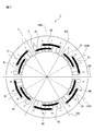
- FIG. 1 is a cross-sectional view (No. 1) for explaining the symmetry of the winding arrangement of the stator in the three-phase AC motor having 10 poles and 36 slots shown in FIG.
- No. 1 is a cross-sectional view (No. 1) for explaining the symmetry of the winding arrangement of the stator in the three-phase AC motor having 10 poles and 36 slots shown in FIG.
- U-phase winding of the stator shown in FIG. It is sectional drawing explaining the symmetry of the V-phase winding of the stator shown in FIG. It is sectional drawing explaining the symmetry of the W phase winding of the stator shown in FIG.
- FIG. 1 is a cross-sectional view (No. 1) for explaining the symmetry of the winding arrangement of the stator in the three-phase AC motor having 10 poles and 36 slots shown in FIG.
- U-phase winding of the stator shown in FIG. It is sectional drawing explaining the symmetry of the V-phase winding of the stator shown in FIG.
- FIG. 2 is a cross-sectional view (No. 2) for explaining the symmetry of the winding arrangement of the stator in the three-phase AC motor of 10 poles and 36 slots shown in FIG. 1, and shows the winding arrangement of the ⁇ U phase band.
- FIG. 2 is a cross-sectional view (No. 2) for explaining the symmetry of the winding arrangement of the stator in the three-phase AC motor of 10 poles and 36 slots shown in FIG. 1, and shows the winding arrangement of the + V phase band.
- FIG. 2 is a cross-sectional view (No. 2) for explaining the symmetry of the winding arrangement of the stator in the three-phase AC motor of 10 poles and 36 slots shown in FIG. 1, and shows the winding arrangement of the ⁇ W phase band.
- FIG. 2 is a cross-sectional view (No. 2) for explaining the symmetry of the winding arrangement of the stator in the three-phase AC motor of 10 poles and 36 slots shown in FIG. 1, and shows the winding arrangement of the ⁇ W phase band.
- FIG. 2 is a cross-sectional view (No. 2) for explaining the symmetry of the winding arrangement of the stator in the three-phase AC motor of 10 poles and 36 slots shown in FIG. 1, and shows the winding arrangement of the + U phase band.
- FIG. 2 is a cross-sectional view (No. 2) for explaining the symmetry of the winding arrangement of the stator in the three-phase AC motor of 10 poles and 36 slots shown in FIG. 1, and shows the winding arrangement of the ⁇ V phase band.
- FIG. 2 is a cross-sectional view (No. 2) for explaining the symmetry of the winding arrangement of the stator in the three-phase AC motor of 10 poles and 36 slots shown in FIG. 1, and shows the winding arrangement of the + W phase band.
- FIG. 8A It is sectional drawing which shows the winding arrangement of the-U phase band shown in FIG. 8A. It is sectional drawing of the stator in the three-phase AC motor of 10 poles and 24 slots according to the embodiment of this disclosure. It is a developed sectional view of the stator shown in FIG. It is a developed sectional view explaining each coil arrangement in the stator shown in FIG. It is sectional drawing of the stator in the three-phase AC motor of 14 poles and 24 slots according to the embodiment of this disclosure. It is a developed sectional view of the stator shown in FIG. It is a developed sectional view explaining each coil arrangement in the stator shown in FIG. FIG.
- FIG. 5 is a cross-sectional view of a stator in a 22-pole 48-slot three-phase AC motor according to an embodiment of the present disclosure. It is a developed sectional view of the stator shown in FIG. FIG. 5 is a cross-sectional view of a stator in a 22-pole 72-slot three-phase AC motor according to an embodiment of the present disclosure. It is a developed sectional view of the stator shown in FIG. It is sectional drawing of the stator in the three-phase AC motor of 34 poles 108 slots according to the embodiment of this disclosure. It is a developed sectional view of the slot identification number 1 to 54 of the stator shown in FIG. It is a developed sectional view of the slot identification number 55 to 108 of the stator shown in FIG.
- FIG. 3 It is a figure which illustrates the appearance of the three-phase AC motor provided with the stator according to the embodiment of this disclosure. It is a figure exemplifying a coil and a three-phase AC electric motor provided with this, and illustrates the coil in the stator shown in FIG. 3, FIG. 12, FIG. 15, FIG. 17, FIG. 19, FIG. 21, FIG. 22, and FIG. 25. do. It is a figure exemplifying a coil and a three-phase AC motor provided with the coil, and illustrates the positional relationship of a stator and a rotor of a three-phase AC motor. It is a developed sectional view explaining the definition of the coil group in the stator according to the embodiment of this disclosure.
- stator having a distributed winding lap coil structure and a three-phase AC motor equipped with the stator will be described.
- similar members are designated by the same reference numerals.
- scales of these drawings have been changed as appropriate for ease of understanding. Further, the form shown in the drawings is an example for carrying out, and is not limited to the illustrated form.
- a wire rod such as a copper wire through which an electric current flows or a bundle of wire rods is referred to as a "winding”.
- a coil in which a closed ring is formed by using a wire and connected in the same shape and overlapped in a bundle is called a "coil”.
- the coil is divided into a portion accommodated in the slot of the stator and a portion not accommodated. When each is clearly separated, the former is referred to as “winding” and the latter is referred to as "coil end”. Further, the number of slots across which the coils housed in the stator slots straddle is referred to as "coil pitch”.
- FIG. 24A is a diagram illustrating a coil and a three-phase AC motor including the coil, and is a stator shown in FIGS. 3, 12, 15, 17, 19, 19, 21, 22, and 25. Illustrate the coil in.
- FIG. 24B is a diagram illustrating a coil and a three-phase AC motor including the coil, and illustrates the positional relationship between a stator and a rotor of the three-phase AC motor.
- the coil 4 includes a positive winding (+ winding) 41P and a negative winding (-winding) 41N accommodated in the slot, and a coil end 42 not accommodated in the slot.
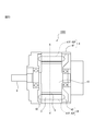
- the rotor 10 is provided so as to face the stator 1 in which the coil (winding) 4 is housed in the slot 2 in the radial direction.
- the rotor 10 is provided with a magnetic pole 21 of a magnet.
- the coil pitch is about 180 degrees in electrical angle per pole, and the mechanical angle.
- a coil pitch of about "180 degrees ⁇ number of poles" is required in terms of conversion.
- the coil pitch is "the integer part in decimal notation which is the quotient of the number of slots ⁇ the value obtained by the number of poles" or "the number of slots ⁇ the value obtained by the number of poles". It is specified by one of the integer part + 1 in decimal notation, which is the quotient of.
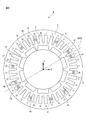
- FIG. 1 is a cross-sectional view of a stator in a 10-pole 36-slot three-phase AC motor according to the embodiment of the present disclosure.
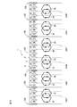
- FIG. 2 is a developed cross-sectional view of the stator shown in FIG.
- FIG. 3 is a developed cross-sectional view illustrating each coil arrangement in the stator shown in FIG. In FIGS. 1 to 3, the magnetic poles of the rotor are not shown.
- U, V, and W represent each phase of three-phase alternating current, and each has a phase difference of ⁇ 120 degrees in electrical angle.
- "+" and "-" indicate the direction of the electric current, and the phase difference thereof is 180 degrees in terms of electric angle.
- each slot 2 provided in the core 3 of the stator 1 two of each of a total of six phase bands of + U, ⁇ U, + V, ⁇ V, + W, and ⁇ W phases are arranged.
- the same number of wires such as copper wires through which current flows are inserted in each arrangement.
- the stator 1 is originally cylindrical, but here, in order to make the explanation easier to understand, a developed cross-sectional view of the cylindrical stator 1 will also be described.
- the number of slots of the slots 2 arranged in the circumferential direction is larger than 1.5 times the number of poles, and the value obtained by dividing the number of slots by the number of poles is an irreducible fraction.
- It is a fractional slot type three-phase AC motor, and includes a stator 1 and a rotor arranged so as to face the stator 1 in the radial direction.
- the number of pole pairs of the rotor of the three-phase AC motor is P
- the number of poles is 2P.
- the number of slots into which the winding of the stator 1 is inserted is 6N
- the value obtained by dividing the number of slots 6N by the number of poles 2P represents the slot pitch of the coil 4.
- a three-phase AC motor in which the value obtained by dividing the number of slots 6N by the number of poles 2P is larger than 1.5 has a coil slot pitch of 2 or more, and requires a distributed winding (overlapping winding) coil structure.
- each of a plurality of coils having the same coil pitch shape is displaced by one slot due to lap winding, and three coils are lap-wound and arranged in the slots.
- the coils that are wound one slot at a time in this way are hereinafter referred to as "the number of continuous coils".
- the number of continuous coils is 3 in all the lap winding sets.
- the stator 1 includes a plurality of sets of coils in which two or three coils 4 having the same coil pitch are arranged in slots with a shift of one slot pitch. Further, the plurality of sets of coils are arranged in six coil groups for all slots, and more specifically, each coil group is arranged at a position shifted by 60 degrees.
- FIG. 25 is a developed cross-sectional view illustrating the definition of the coil group in the stator according to the embodiment of the present disclosure.
- the term "set (of coils)” means a group consisting of a plurality of (three in the example shown in FIG. 25) coils having the same coil pitch shape by lap winding.
- the "coil group” means a group each of which is composed of a plurality of sets of coils and is arranged at positions shifted by 60 degrees.
- each of the six coil groups will be referred to as a first coil group, a second coil group, a third coil group, a fourth coil group, a fifth coil group, and a sixth coil group.
- each coil is formed to have the same coil pitch, and is arranged in a slot by lap winding with a shift of one slot pitch.
- the quotient 3 which is an integer part in the decimal notation of the value obtained by dividing the number of slots 36 by the number of poles 10 is fixed. It becomes the coil pitch of the child. Further, since the number of slots of the stator 1 is 36, each of the U-phase, V-phase, and W-phase coils is evenly divided into six coil groups over the entire 36 slots, and lap winding is performed in each group. It will be possible. As shown in FIG. 2, the number of continuous coils for lap winding of 10 poles and 36 slots is 3.
- each set the three coils have a coil pitch of 3, and one set of lap windings is formed in 6 slots, and the sets are arranged apart from each other.
- Each of these three coils is configured as a U-phase winding, which is a first-phase winding, a V-phase winding, which is a second-phase winding, and a W-phase winding, which is a third-phase winding. Specifically, it is as follows.
- each of the three coils U1, W1, and V1 having the same coil pitch is arranged in slots offset by one slot pitch. More specifically, in the coil U1, the directions of the currents flowing in the winding arranged in the slot of the slot identification number 1 and the winding arranged in the slot of the slot identification number 4 with a deviation of 3 coil pitches are opposite to each other. It is formed in this way and placed in the slots of slot identification numbers 1 and 4.
- the coil W1 is arranged in a slot shifted by one slot from the coil V1. That is, the coil W1 is formed so that the directions of the currents flowing in the winding arranged in the slot of the slot identification number 2 and the winding arranged in the slot of the slot identification number 5 are opposite to each other.
- the coil V1 is arranged in a slot shifted by one slot from the coil W1. That is, the coil V1 is formed so that the directions of the currents flowing in the winding arranged in the slot of the slot identification number 3 and the winding arranged in the slot of the slot identification number 6 are opposite to each other. It is placed in the slots of identification numbers 3 and 6.
- each of the three coils V2, U2, and W2 having the same coil pitch is arranged in slots offset by one slot pitch.
- the second coil group is arranged at a position deviated by 60 degrees in the circumferential direction (clockwise in the example shown in FIG. 1) from the first coil group. More specifically, the coil V2 is formed so that the directions of the currents flowing in the winding arranged in the slot of slot identification number 7 and the winding arranged in the slot of slot identification number 10 are opposite to each other. , Placed in slots with slot identification numbers 7 and 10.
- the coil U2 is arranged in a slot shifted by one slot from the coil V2.
- the coil U2 is formed so that the directions of the currents flowing in the winding arranged in the slot of the slot identification number 8 and the winding arranged in the slot of the slot identification number 11 are opposite to each other. It is arranged in the slots of identification numbers 8 and 11.
- the coil W2 is arranged in a slot shifted by one slot from the coil U2. That is, the coil W2 is formed so that the directions of the currents flowing in the winding arranged in the slot of the slot identification number 9 and the winding arranged in the slot of the slot identification number 12 are opposite to each other. It is arranged in the slots of identification numbers 9 and 12.
- each of the three coils W3, V3, and U3 having the same coil pitch is arranged in slots offset by one slot pitch. Further, the third coil group is arranged at a position deviated by 60 degrees from the second coil group in the same direction as the circumferential direction (that is, clockwise). More specifically, the coil W3 is formed so that the directions of the currents flowing in the winding arranged in the slot of the slot identification number 13 and the winding arranged in the slot of the slot identification number 16 are opposite to each other. , Are placed in the slots of slot identification numbers 13 and 16. The coil V3 is arranged in a slot shifted by one slot from the coil W3.
- the coil V3 is formed so that the directions of the currents flowing in the winding arranged in the slot of the slot identification number 14 and the winding arranged in the slot of the slot identification number 17 are opposite to each other. It is arranged in the slots of identification numbers 14 and 17.
- the coil U3 is arranged in a slot shifted by one slot from the coil V3. That is, the coil U3 is formed so that the directions of the currents flowing in the winding arranged in the slot of the slot identification number 15 and the winding arranged in the slot of the slot identification number 18 are opposite to each other. It is placed in the slots of identification numbers 15 and 18.
- each of the three coils U4, W4, and V4 having the same coil pitch is arranged in slots offset by one slot pitch. Further, the fourth coil group is arranged at a position deviated by 60 degrees from the third coil group in the same direction as the circumferential direction (that is, clockwise). More specifically, the coil U4 is formed so that the directions of the currents flowing in the winding arranged in the slot of slot identification number 19 and the winding arranged in the slot of slot identification number 22 are opposite to each other. , Placed in slots of slot identification numbers 19 and 22. The coil W4 is arranged in a slot shifted by one slot from the coil U4.
- the coil W4 is formed so that the directions of the currents flowing in the winding arranged in the slot of the slot identification number 20 and the winding arranged in the slot of the slot identification number 23 are opposite to each other. It is arranged in the slots of identification numbers 20 and 23.
- the coil V4 is arranged in a slot shifted by one slot from the coil W4. That is, the coil V4 is formed so that the directions of the currents flowing in the winding arranged in the slot of the slot identification number 21 and the winding arranged in the slot of the slot identification number 24 are opposite to each other. It is arranged in the slots of identification numbers 21 and 24.
- each of the three coils V5, U5, and W5 having the same coil pitch is arranged in slots offset by one slot pitch. Further, the fifth coil group is arranged at a position deviated by 60 degrees from the fourth coil group in the same direction as the circumferential direction (that is, clockwise). More specifically, the coil V5 is formed so that the directions of the currents flowing in the winding arranged in the slot of slot identification number 25 and the winding arranged in the slot of slot identification number 28 are opposite to each other. , Placed in slots of slot identification numbers 25 and 28. The coil U5 is arranged in a slot shifted by one slot from the coil V5.
- the coil U5 is formed so that the directions of the currents flowing in the winding arranged in the slot of the slot identification number 26 and the winding arranged in the slot of the slot identification number 29 are opposite to each other. It is arranged in the slots of identification numbers 26 and 29.
- the coil W5 is arranged in a slot shifted by one slot from the coil U5. That is, the coil W5 is formed so that the directions of the currents flowing in the winding arranged in the slot of the slot identification number 27 and the winding arranged in the slot of the slot identification number 30 are opposite to each other. It is arranged in the slots of identification numbers 27 and 30.
- each of the three coils W6, V6, and U6 having the same coil pitch is arranged in slots offset by one slot pitch. Further, the sixth coil group is arranged at a position deviated by 60 degrees from the fifth coil group in the same direction as the circumferential direction (that is, clockwise). More specifically, the coil W6 is formed so that the directions of the currents flowing in the winding arranged in the slot of the slot identification number 31 and the winding arranged in the slot of the slot identification number 34 are opposite to each other. , Slot identification numbers 31 and 34. The coil V6 is arranged in a slot shifted by one slot from the coil W6.
- the coil V6 is formed so that the directions of the currents flowing in the winding arranged in the slot of the slot identification number 32 and the winding arranged in the slot of the slot identification number 35 are opposite to each other. It is arranged in the slots of identification numbers 32 and 35.
- the coil U6 is arranged in a slot that is one slot bitch offset from the coil V6. That is, the coil U6 is formed so that the directions of the currents flowing in the winding arranged in the slot of the slot identification number 33 and the winding arranged in the slot of the slot identification number 36 are opposite to each other. It is arranged in the slots of identification numbers 33 and 36.
- the coils U1, U2, U3, U4, U5, and U6 described above are connected by a crossover and are configured as a U-phase winding in the stator 1. Further, the coils V1, V2, V3, V4, V5, and V6 described above are connected by a crossover wire and are configured as a V-phase winding in the stator 1. Further, the coils W1, W2, W3, W4, W5, and W6 described above are connected by a crossover wire and are configured as a W-phase winding in the stator 1.
- the 10-pole 36-slot three-phase AC motor includes the above-mentioned stator 1 and rotors arranged radially opposite to the stator 1.
- stator slots of the subject of the present invention is limited to a multiple of 6.
- Form (III) When N / P> 2 (or the number of slots ⁇ the number of poles> 4), there is no method of lap winding in which one layer can be wound per slot. That is, the embodiment of the present disclosure is not applicable.
- N is a value obtained by dividing the number of slots 6N by 6, and is an integer. Further, P is an odd number of 5 or more.
- the value obtained by dividing the number of slots 36 by the number of poles 10 is 3.6, which corresponds to the case of the above-mentioned form (II).
- the coil pitch is 3
- the number of continuous coils is 3
- the number of continuous lap winding occupied slots is 6.
- FIG. 4 is a cross-sectional view illustrating the symmetry of the winding arrangement of the stator in the 10-pole 36-slot three-phase AC motor shown in FIG.
- FIG. 5 is a cross-sectional view illustrating the symmetry of the U-phase winding of the stator shown in FIG.
- FIG. 6 is a cross-sectional view illustrating the symmetry of the V-phase winding of the stator shown in FIG.
- FIG. 7 is a cross-sectional view illustrating the symmetry of the W-phase winding of the stator shown in FIG.
- the magnetic pole 21 of the rotor 10 is also shown.
- the stator of the 10-pole 36-slot three-phase AC motor shown in FIG. 1 in the first coil group U1, the second coil group U2, and the third coil group U3, as shown in FIGS. 4 and 5.
- the first-phase winding (U-phase winding) and the first-phase winding (U-phase winding) in the sixth coil group U6, the fifth coil group U5, and the fourth coil group U4 are stators. It is arranged line-symmetrically with respect to the first axis of symmetry 100U on the peripheral plane of 1. Further, as shown in FIGS. 4 and 6, the second coil group V2, the third coil group V3, and the second coil group V4 in the second coil group V2, the second coil group V4, and the first coil.
- the second phase winding (V phase winding) in the group V1, the sixth coil group V6, and the fifth coil group V5 is axisymmetric with respect to the second axis of symmetry 100V on the circumferential plane of the stator 1. Is placed in. Further, as shown in FIGS. 4 and 7, the third phase winding (W phase winding) and the second coil in the third coil group W3, the fourth coil group W4, and the fifth coil group W5.
- the third phase winding (W phase winding) in the group W2, the first coil group W1 and the sixth coil group W6 is axisymmetric with respect to the third axis of symmetry 100W on the circumferential plane of the stator 1. Is placed in.
- the first axis of symmetry 100U, the second axis of symmetry 100V, and the third axis of symmetry 100W are arranged so as to be offset from each other by 60 degrees.
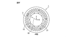
- FIG. 8A is a cross-sectional view (No. 2) for explaining the symmetry of the winding arrangement of the stator in the three-phase AC motor of 10 poles and 36 slots shown in FIG. show.
- FIG. 8B is a cross-sectional view (No. 2) for explaining the symmetry of the winding arrangement of the stator in the three-phase AC motor of 10 poles and 36 slots shown in FIG. 1, showing the winding arrangement of the + V phase band. ..
- FIG. 8C is a cross-sectional view (No. 2) for explaining the symmetry of the winding arrangement of the stator in the three-phase AC motor of 10 poles and 36 slots shown in FIG. show.
- FIG. 8D is a cross-sectional view (No.
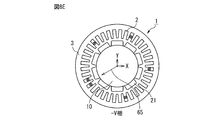
- FIG. 8E is a cross-sectional view (No. 2) for explaining the symmetry of the winding arrangement of the stator in the three-phase AC motor of 10 poles and 36 slots shown in FIG. show.
- FIG. 8F is a cross-sectional view (No. 2) for explaining the symmetry of the winding arrangement of the stator in the three-phase AC motor of 10 poles and 36 slots shown in FIG. 1, and shows the winding arrangement of the + W phase band. .. In FIG.
- reference numeral 61 is a line symmetry axis of the ⁇ U phase band and indicates a vector indicating the arrangement direction.
- reference numeral 62 is a line symmetry axis of the + V phase band and indicates a vector indicating the arrangement direction.
- reference numeral 63 indicates a vector indicating the arrangement direction, which is the axis of line symmetry of the ⁇ W phase band.
- reference numeral 64 is a line symmetry axis of the + U phase band and indicates a vector indicating the arrangement direction.
- reference numeral 65 is a line symmetry axis of the ⁇ V phase band and indicates a vector indicating the arrangement direction.
- reference numeral 66 is a line symmetry axis of the + W phase band and indicates a vector indicating the arrangement direction.
- FIG. 9 is a cross-sectional view showing the winding arrangement of the ⁇ U phase band shown in FIG. 8A.
- the slot pitch to the adjacent winding may be 70 degrees for windings in the same phase band (-U phase band in the example shown in FIG. 9).
- the number of pole pairs is an odd number of 5 or more, the axis of line symmetry always exists. This is based on the following reasons.
- the winding arrangement When the winding arrangement is optimized so that the waveform of the induced voltage generated in the stator coil approaches a sine wave for each of the six phase bands of ⁇ U, ⁇ V, and ⁇ W, the winding of each phase band Are arranged so as to be evenly distributed and at a slot pitch close to the value of 360 ⁇ pole logarithm P, so that the windings are arranged so as to approach a regular P square (where P is pole logarithm).
- the regular P-side has P-fold rotational symmetry, and also has line symmetry about each vertex and a line perpendicular to the center of the opposite side of the vertex.
- FIG. 9 shows the arrangement of the windings of the ⁇ U phase among the 6 phase bands of ⁇ U, ⁇ V, and ⁇ W.
- the winding arrangement of is close to a regular pentagon.
- the slot pitch from one -U phase winding to the adjacent -U winding is preferably a mechanical angle of 72 degrees for one electrical angle cycle.
- the slot pitch of -U6 and -U1 is 10 degrees for one slot, -U1 and -U2, -U2 and -U3, -U3 and -U4, -U4 and -U5, and -U5 and -U6.
- the winding arrangement of each of the remaining five-phase bands also has no rotational symmetry, but has an axis of line symmetry.
- the line symmetry axis 100U for the -U phase and the + U phase the line symmetry axis 100V for the -V phase and the + V phase, and the -W phase and the + W phase.
- the line symmetry axis 100W of is coincided with the line that divides the coil group.
- the U-phase windings are arranged so as to have one axis that is line-symmetric, and the V-phase windings are arranged so that they have one axis that is line-symmetrical.
- the W-phase windings are arranged so as to have one axis that is axisymmetric. That is, the U-phase windings are arranged line-symmetrically with respect to the line-symmetry axis 100U, the V-phase windings are arranged line-symmetrically with respect to the line-symmetry axis 100V, and the W-phase windings are arranged line-symmetrically with respect to the line-symmetry axis 100W. Arranged line-symmetrically. This is a feature of a three-phase AC motor in which the pole logarithm P is an odd number and the value obtained by dividing the number of slots by the number of poles is a specified fraction.
- the number of continuous coils for lap winding is 2, and two of the three phases are assigned to two coils for lap winding, so that one set of lap winding has three phases. Becomes uneven. Therefore, a certain one-phase axisymmetric axis is positioned so as to divide the set of the remaining two-phase lap winding from the center, and intersects with the coil ends of the remaining two-phase coils.
- the number of continuous coils for lap winding is 3, and all three of the three phases are evenly allocated in each set of lap winding, so that the coil group that divides the slot evenly. The dividing line of is always coincident with the line symmetry axis of each phase.
- the axisymmetric axes 100U, 100V, and 100W of the windings of each phase coincide with the lines that divide the first to sixth coil groups. ..
- FIG. 10 is a cross-sectional view of a stator in a 10-pole 24-slot three-phase AC motor according to the embodiment of the present disclosure.
- FIG. 11 is a developed cross-sectional view of the stator shown in FIG.
- FIG. 12 is a developed cross-sectional view illustrating each coil arrangement in the stator shown in FIG. In FIGS. 10 to 12, the magnetic poles of the rotor are not shown.
- a three-phase AC motor with 10 poles and 24 slots satisfies the requirement that "the number of slots is greater than 1.5 times the number of poles" because the value obtained by dividing the number of slots 24 by the number of poles 10 is 2.4. Further, since 12/5, which is the value obtained by dividing the number of slots 24 by the number of poles 10, is an irreducible fraction, it can be said to be a fractional slot type.
- the 10-pole 24-slot three-phase AC motor corresponds to the case of the form (I), the coil pitch is 2, and the number of continuous coils is 2. Therefore, two coils having a coil pitch of 2 and one set are arranged over the four slots with the slot pitch shifted by one. Therefore, since the number of slots of the stator 1 is 24, each of the U-phase, V-phase, and W-phase coils is evenly divided into six coil groups over the entire 24 slots, and lap winding is performed in each group. It will be possible.
- Each of the two coils in each set of these lap windings is a U-phase winding which is a first-phase winding, a V-phase winding which is a second-phase winding, and a W-phase winding which is a third-phase winding. It is configured as any two of them.
- each of the two coils W1 and V1 having the same coil pitch are arranged in slots shifted by one slot pitch. More specifically, in the coil W1, the directions of the currents flowing in the winding arranged in the slot of the slot identification number 1 and the winding arranged in the slot of the slot identification number 3 with a deviation of 2 coil pitches are opposite to each other. It is formed in this way and placed in the slots of slot identification numbers 1 and 3.
- the coil V1 is arranged in a slot shifted by one slot from the coil W1. That is, the coil V1 is formed so that the directions of the currents flowing in the winding arranged in the slot of the slot identification number 2 and the winding arranged in the slot of the slot identification number 4 are opposite to each other. It is arranged in the slots of identification numbers 2 and 4.
- each of the two coils U2 and W2 having the same coil pitch are arranged in slots shifted by one slot pitch.
- the second coil group is arranged at a position deviated by 60 degrees in the circumferential direction (clockwise in the example shown in FIG. 10) from the first coil group. More specifically, the coil U2 is formed so that the directions of the currents flowing in the winding arranged in the slot of slot identification number 5 and the winding arranged in the slot of slot identification number 7 are opposite to each other. , Placed in slots with slot identification numbers 5 and 7.
- the coil W2 is arranged in a slot shifted by one slot from the coil U2.
- the coil W2 is formed so that the directions of the currents flowing in the winding arranged in the slot of the slot identification number 6 and the winding arranged in the slot of the slot identification number 8 are opposite to each other. It is placed in the slots of identification numbers 6 and 8.
- each of the two coils V3 and U3 having the same coil pitch are arranged in slots shifted by one slot pitch.
- the third coil group is arranged at a position deviated by 60 degrees from the second coil group in the same direction as the circumferential direction (that is, clockwise). More specifically, the coil V3 is formed so that the directions of the currents flowing in the winding arranged in the slot of slot identification number 9 and the winding arranged in the slot of slot identification number 11 are opposite to each other. , Slot identification numbers 9 and 11.
- the coil U3 is arranged in a slot shifted by one slot from the coil V3.
- the coil U3 is formed so that the directions of the currents flowing in the winding arranged in the slot of the slot identification number 10 and the winding arranged in the slot of the slot identification number 12 are opposite to each other. It is arranged in the slots of identification numbers 10 and 12.
- each of the two coils W4 and V4 having the same coil pitch are arranged in slots offset by one slot pitch. Further, the fourth coil group is arranged at a position deviated by 60 degrees from the third coil group in the same direction as the circumferential direction (that is, clockwise). More specifically, the coil W4 is formed so that the directions of the currents flowing in the winding arranged in the slot of the slot identification number 13 and the winding arranged in the slot of the slot identification number 15 are opposite to each other. , Placed in slots of slot identification numbers 13 and 15. The coil V4 is arranged in a slot shifted by one slot from the coil W4.
- the coil V4 is formed so that the directions of the currents flowing in the winding arranged in the slot of the slot identification number 14 and the winding arranged in the slot of the slot identification number 16 are opposite to each other. It is arranged in the slots of identification numbers 14 and 16.
- each of the two coils U5 and W5 having the same coil pitch are arranged in slots offset by one slot pitch.
- the fifth coil group is arranged at a position deviated by 60 degrees from the fourth coil group in the same direction as the circumferential direction (that is, clockwise). More specifically, the coil U5 is formed so that the directions of the currents flowing in the winding arranged in the slot of slot identification number 17 and the winding arranged in the slot of slot identification number 19 are opposite to each other. , Placed in slots of slot identification numbers 17 and 19.
- the coil W5 is arranged in a slot shifted by one slot from the coil U5.
- the coil W5 is formed so that the directions of the currents flowing in the winding arranged in the slot of the slot identification number 18 and the winding arranged in the slot of the slot identification number 20 are opposite to each other. It is arranged in the slots of identification numbers 18 and 20.
- each of the two coils V6 and U6 having the same coil pitch are arranged in slots shifted by one slot pitch. Further, the sixth coil group is arranged at a position deviated by 60 degrees from the fifth coil group in the same direction as the circumferential direction (that is, clockwise). More specifically, the coil V6 is formed so that the directions of the currents flowing in the winding arranged in the slot of the slot identification number 21 and the winding arranged in the slot of the slot identification number 23 are opposite to each other. , Are arranged in the slots of slot identification numbers 21 and 23.
- the coil U6 is arranged in a slot that is one slot bitch offset from the coil V6.
- the coil U6 is formed so that the directions of the currents flowing in the winding arranged in the slot of the slot identification number 22 and the winding arranged in the slot of the slot identification number 24 are opposite to each other. It is arranged in the slots of identification numbers 22 and 24.
- the coils U2, U3, U5, and U6 described above are connected by a crossover and are configured as a U-phase winding in the stator 1. Further, the coils V1, V3, V4, and V6 described above are connected by a crossover wire and are configured as a V-phase winding in the stator 1. Further, the coils W1, W2, W4, and W5 described above are connected by a crossover wire and are configured as a W-phase winding in the stator 1.
- the 10-pole 24-slot three-phase AC motor includes the above-mentioned stator 1 and rotors arranged radially opposite to the stator 1.
- line symmetry axes 100U, 100V, and 100W of the windings of each phase do not match the line 100 that divides the first to sixth coil groups.
- FIG. 13 is a cross-sectional view of a stator in a 14-pole 24-slot three-phase AC motor according to the embodiment of the present disclosure.
- FIG. 14 is a developed cross-sectional view of the stator shown in FIG.
- FIG. 15 is a developed cross-sectional view illustrating each coil arrangement in the stator shown in FIG. In FIGS. 13 to 15, the magnetic poles of the rotor are not shown.
- a three-phase AC motor with 14 poles and 24 slots satisfies the requirement that "the number of slots is greater than 1.5 times the number of poles" because the value obtained by dividing the number of slots 24 by the number of poles 14 is about 1.7. Further, since 12/7, which is the value obtained by dividing the number of slots 24 by the number of poles 14, is an irreducible fraction, it can be said to be a fractional slot type.
- the value obtained by dividing the number of slots 24 by the number of poles 14 is about 1.7, which corresponds to the case of the form (I).
- the coil pitch is 2 and the number of continuous coils is 2. Therefore, two coils having a coil pitch of 2 and a slot pitch shifted by one are arranged in a set over four slots. Therefore, the U-phase, V-phase, and W-phase coils are evenly divided into six coil groups over the entire 24 slots, and separate lap winding is possible in each coil group.
- Each of the two coils in each set of these lap windings is a U-phase winding which is a first-phase winding, a V-phase winding which is a second-phase winding, and a W-phase winding which is a third-phase winding. It is configured as any two of them.
- each of the two coils W1 and U1 having the same coil pitch are arranged in slots shifted by one slot pitch. More specifically, in the coil W1, the directions of the currents flowing in the winding arranged in the slot of the slot identification number 1 and the winding arranged in the slot of the slot identification number 3 with a deviation of 2 coil pitches are opposite to each other. It is formed in this way and placed in the slots of slot identification numbers 1 and 3.
- the coil U1 is arranged in a slot shifted by one slot from the coil W1. That is, the coil U1 is formed so that the directions of the currents flowing in the winding arranged in the slot of the slot identification number 2 and the winding arranged in the slot of the slot identification number 4 are opposite to each other. It is arranged in the slots of identification numbers 2 and 4.
- each of the two coils V2 and W2 having the same coil pitch are arranged in slots shifted by one slot pitch.
- the second coil group is arranged at a position deviated by 60 degrees in the circumferential direction (clockwise in the example shown in FIG. 13) from the first coil group. More specifically, the coil V2 is formed so that the directions of the currents flowing in the winding arranged in the slot of slot identification number 5 and the winding arranged in the slot of slot identification number 7 are opposite to each other. , Placed in slots with slot identification numbers 5 and 7.
- the coil W2 is arranged in a slot shifted by one slot from the coil U2.
- the coil W2 is formed so that the directions of the currents flowing in the winding arranged in the slot of the slot identification number 6 and the winding arranged in the slot of the slot identification number 8 are opposite to each other. It is placed in the slots of identification numbers 6 and 8.
- each of the two coils U3 and V3 having the same coil are arranged in slots shifted by one slot pitch. Further, the third coil group is arranged at a position deviated by 60 degrees from the second coil group in the same direction as the circumferential direction (that is, clockwise). More specifically, the coil U3 is formed so that the directions of the currents flowing in the winding arranged in the slot of slot identification number 9 and the winding arranged in the slot of slot identification number 11 are opposite to each other. , Slot identification numbers 9 and 11. The coil V3 is arranged in a slot shifted by one slot from the coil U3.
- the coil V3 is formed so that the directions of the currents flowing in the winding arranged in the slot of the slot identification number 10 and the winding arranged in the slot of the slot identification number 12 are opposite to each other. It is arranged in the slots of identification numbers 10 and 12.
- each of the two coils W4 and U4 having the same coil pitch are arranged in slots offset by one slot pitch. Further, the fourth coil group is arranged at a position deviated by 60 degrees from the third coil group in the same direction as the circumferential direction (that is, clockwise). More specifically, the coil W4 is formed so that the directions of the currents flowing in the winding arranged in the slot of the slot identification number 13 and the winding arranged in the slot of the slot identification number 15 are opposite to each other. , Placed in slots of slot identification numbers 13 and 15. The coil U4 is arranged in a slot shifted by one slot from the coil W4.
- the coil U4 is formed so that the directions of the currents flowing in the winding arranged in the slot of the slot identification number 14 and the winding arranged in the slot of the slot identification number 16 are opposite to each other. It is arranged in the slots of identification numbers 14 and 16.
- each of the two coils V5 and U5 having the same coil pitch are arranged in slots offset by one slot pitch.
- the fifth coil group is arranged at a position deviated by 60 degrees from the fourth coil group in the same direction as the circumferential direction (that is, clockwise). More specifically, the coil V5 is formed so that the directions of the currents flowing in the winding arranged in the slot of the slot identification number 17 and the winding arranged in the slot of the slot identification number 19 are opposite to each other. , Placed in slots of slot identification numbers 17 and 19.
- the coil U5 is arranged in a slot shifted by one slot from the coil V5.
- the coil U5 is formed so that the directions of the currents flowing in the winding arranged in the slot of the slot identification number 18 and the winding arranged in the slot of the slot identification number 20 are opposite to each other. It is arranged in the slots of identification numbers 18 and 20.
- each of the two coils U6 and V6 having the same coil pitch are arranged in slots shifted by one slot pitch.
- the sixth coil group is arranged at a position deviated by 60 degrees from the fifth coil group in the same direction as the circumferential direction (that is, clockwise). More specifically, the coil U6 is formed so that the directions of the currents flowing in the winding arranged in the slot of the slot identification number 21 and the winding arranged in the slot of the slot identification number 23 are opposite to each other. , Are arranged in the slots of slot identification numbers 21 and 23.
- the coil V6 is arranged in a slot shifted by one slot from the coil U6.
- the coil V6 is formed so that the directions of the currents flowing in the winding arranged in the slot of the slot identification number 22 and the winding arranged in the slot of the slot identification number 24 are opposite to each other. It is arranged in the slots of identification numbers 22 and 24.
- the coils U1, U3, U5, and U6 described above are connected by a crossover and are configured as a U-phase winding in the stator 1. Further, the coils V2, V3, V5, and V6 described above are connected by a crossover wire and are configured as a V-phase winding in the stator 1. Further, the coils W1, W2, W4, and W6 described above are connected by a crossover and are configured as a W-phase winding in the stator 1.
- the 14-pole, 24-slot three-phase AC motor includes the above-mentioned stator 1 and rotors arranged radially opposite to the stator 1.
- line symmetry axes 100U, 100V, and 100W of the windings of each phase do not match the line 100 that divides the first to sixth coil groups.
- FIG. 16 is a cross-sectional view of a stator in a 22-pole 48-slot three-phase AC motor according to the embodiment of the present disclosure. Further, FIG. 17 is a developed cross-sectional view of the stator shown in FIG.
- a 22-pole 48-slot three-phase AC motor satisfies the requirement that "the number of slots is greater than 1.5 times the number of poles" because the value obtained by dividing the number of slots 48 by the number of poles 22 is about 2.2. Further, since 24/11, which is the value obtained by dividing the number of slots 48 by the number of poles 22, is an irreducible fraction, it can be said to be a fractional slot type.
- the 22-pole 48-slot three-phase AC motor corresponds to the case of the form (I), the coil pitch is 2, and the number of continuous coils is 2. Therefore, two coils having a coil pitch of 2 and a slot pitch shifted by one, and one set of lap windings is arranged over the four slots. Then, another set of lap windings spanning 4 slots is arranged so that the coil pitch is 2 and the continuous coil 2 is further deviated by 4 slots in the circumferential direction from this 1 set of lap windings, and a total of 2 sets of lap windings are formed. It is arranged over 8 slots.
- each of the two coils in each lap winding set is a U-phase winding which is a first-phase winding, a V-phase winding which is a second-phase winding, and a W-phase which is a third-phase winding. It is configured as either two phases of the winding.
- the directions of the currents flowing in the winding arranged in the slot of the slot identification number 1 and the winding arranged in the slot of the slot identification number 3 with a deviation of 2 coil pitches are opposite to each other.
- the coil W1-1 is arranged in a slot shifted by one slot from the coil U1-1. That is, in the coil W1-1, the directions of the currents flowing in the winding arranged in the slot of the slot identification number 2 and the winding arranged in the slot of the slot identification number 4 having a deviation of 2 coil pitches are opposite to each other. It is formed in this way and placed in the slots of slot identification numbers 2 and 4.
- the coil U1-2 is arranged in a slot shifted by 4 slots from the coil U1-1.
- the directions of the currents flowing in the winding arranged in the slot of the slot identification number 5 and the winding arranged in the slot of the slot identification number 7 having a deviation of 2 coil pitches are opposite to each other.
- the coil V1-2 is arranged in a slot shifted by one slot bitch from the coil U1-2. That is, in the coil V1-2, the directions of the currents flowing in the winding arranged in the slot of the slot identification number 6 and the winding arranged in the slot of the slot identification number 8 having a deviation of 2 coil pitches are opposite to each other. And placed in the slots of slot identification numbers 6 and 8.
- the second coil group a set of lap windings in which two coils W2-1 and V2-1 having the same coil pitch are arranged in slots deviated by one slot pitch, and this one set A set of lap windings in which two coils W2-2 and U2-2 having the same coil pitch are arranged in slots shifted by one slot pitch from the lap winding in the circumferential direction. Is formed. Further, the second coil group is arranged at a position deviated by 60 degrees in the circumferential direction (clockwise in the example shown in FIG. 16) from the first coil group.
- the directions of the currents flowing in the winding arranged in the slot of the slot identification number 9 and the winding arranged in the slot of the slot identification number 11 having a two coil pitch shift are opposite to each other. It is molded so as to be and placed in the slots of slot identification numbers 9 and 11.
- the coil V2-1 is arranged in a slot shifted by one slot bitch from the coil W2-1. That is, in the coil V2-1, the directions of the currents flowing in the winding arranged in the slot of the slot identification number 10 and the winding arranged in the slot of the slot identification number 12 having a deviation of 2 coil pitches are opposite to each other. And placed in the slots of slot identification numbers 10 and 12.
- the coil W2-2 is arranged in a slot shifted by 4 slots from the coil W2-1. That is, in the coil W2-2, the directions of the currents flowing in the winding arranged in the slot of the slot identification number 13 and the winding arranged in the slot of the slot identification number 15 having a two coil pitch shift are opposite to each other. And placed in the slots of slot identification numbers 13 and 15.
- the coil U2-2 is arranged in a slot shifted by one slot bitch from the coil W2-2. That is, in the coil U2-2, the directions of the currents flowing in the winding arranged in the slot of the slot identification number 14 and the winding arranged in the slot of the slot identification number 16 having a two coil pitch shift are opposite to each other. And placed in the slots of slot identification numbers 14 and 16.
- the third coil group a set of lap windings in which two coils V3-1 and U3-1 having the same coil pitch are arranged in slots offset by one slot pitch, and a set of lap windings.
- the third coil group is arranged at a position deviated by 60 degrees in the circumferential direction (clockwise in the example shown in FIG. 16) from the second coil group.
- the directions of the currents flowing in the winding arranged in the slot of the slot identification number 17 and the winding arranged in the slot of the slot identification number 19 having a two coil pitch shift are opposite to each other. It is formed so as to be, and is arranged in the slots of the slot identification numbers 17 and 19.
- the coil U3-1 is arranged in a slot shifted by one slot from the coil V3-1. That is, in the coil U3-1, the directions of the currents flowing in the winding arranged in the slot of the slot identification number 18 and the winding arranged in the slot of the slot identification number 20 having a deviation of 2 coil pitches are opposite to each other. And placed in the slots of slot identification numbers 18 and 20.
- the coil V3-2 is arranged in a slot shifted by 4 slots from the coil V3-1. That is, in the coil V3-2, the directions of the currents flowing in the winding arranged in the slot of the slot identification number 21 and the winding arranged in the slot of the slot identification number 23 with a deviation of 2 coil pitches are opposite to each other. It is formed so as to be arranged in the slots of slot identification numbers 21 and 23.
- the coil W3-2 is arranged in a slot shifted by one slot from the coil V3-2. That is, in the coil W3-2, the directions of the currents flowing in the winding arranged in the slot of the slot identification number 22 and the winding arranged in the slot of the slot identification number 24 with a deviation of 2 coil pitches are opposite to each other. And placed in the slots of slot identification numbers 22 and 24.
- the fourth coil group a set of lap windings in which two coils U4-1 and W4-1 having the same coil pitch are arranged in slots offset by one slot pitch, and this one set A set of lap windings in which two coils U4-2 and V4-2 having the same coil pitch are arranged in slots shifted by one slot pitch from the lap winding in the circumferential direction. Is formed. Further, the fourth coil group is arranged at a position deviated by 60 degrees in the circumferential direction (clockwise in the example shown in FIG. 16) from the third coil group.
- the directions of the currents flowing in the winding arranged in the slot of the slot identification number 25 and the winding arranged in the slot of the slot identification number 27 deviated by two coil pitches are opposite to each other. It is molded so as to be and placed in the slots of slot identification numbers 25 and 27.
- the coil W4-1 is arranged in a slot shifted by one slot from the coil U4-1. That is, in the coil W4-1, the directions of the currents flowing in the winding arranged in the slot of the slot identification number 26 and the winding arranged in the slot of the slot identification number 28 deviated by two coil pitches are opposite to each other. And placed in the slots of slot identification numbers 26 and 28.
- the coil U4-2 is arranged in a slot shifted by 4 slots from the coil U4-1. That is, in the coil U4-2, the directions of the currents flowing in the winding arranged in the slot of the slot identification number 29 and the winding arranged in the slot of the slot identification number 31 deviated by two coil pitches are opposite to each other. And are placed in the slots of slot identification numbers 29 and 31.
- the coil V4-2 is arranged in a slot shifted by one slot from the coil U4-2. That is, in the coil V4-2, the directions of the currents flowing in the winding arranged in the slot of the slot identification number 30 and the winding arranged in the slot of the slot identification number 32 deviated by two coil pitches are opposite to each other. And placed in the slots of slot identification numbers 30 and 32.
- the fifth coil group a set of lap windings in which two coils W5-1 and V5-1 having the same coil pitch are arranged in slots deviated by one slot pitch, and a set of the lap windings.
- the fifth coil group is arranged at a position deviated by 60 degrees in the circumferential direction (clockwise in the example shown in FIG. 16) from the fourth coil group.
- the directions of the currents flowing in the winding arranged in the slot of the slot identification number 33 and the winding arranged in the slot of the slot identification number 35 deviated by two coil pitches are opposite to each other. It is molded so as to be and placed in the slots of slot identification numbers 33 and 35.
- the coil V5-1 is arranged in a slot shifted by one slot bitch from the coil W5-1. That is, in the coil V5-1, the directions of the currents flowing in the winding arranged in the slot of the slot identification number 34 and the winding arranged in the slot of the slot identification number 36 deviated by two coil pitches are opposite to each other. And placed in the slots of slot identification numbers 34 and 36.
- the coil W5-2 is arranged in a slot shifted by 4 slots from the coil S5-1. That is, in the coil W5-2, the directions of the currents flowing in the winding arranged in the slot of the slot identification number 37 and the winding arranged in the slot of the slot identification number 39 deviated by two coil pitches are opposite to each other. And placed in the slots of slot identification numbers 37 and 39.
- the coil U5-2 is arranged in a slot shifted by one slot bitch from the coil W5-2. That is, in the coil U5-2, the directions of the currents flowing in the winding arranged in the slot of the slot identification number 38 and the winding arranged in the slot of the slot identification number 40 deviated by two coil pitches are opposite to each other. And placed in the slots of slot identification numbers 38 and 40.
- the sixth coil group a set of lap windings in which two coils V6-1 and U6-1 having the same coil pitch are arranged in slots offset by one slot pitch, and a set of lap windings.
- the sixth coil group is arranged at a position deviated by 60 degrees in the circumferential direction (clockwise in the example shown in FIG. 16) from the fifth coil group.
- the directions of the currents flowing in the winding arranged in the slot of the slot identification number 41 and the winding arranged in the slot of the slot identification number 43 shifted by two coil pitches are opposite to each other. It is formed so as to be, and is arranged in the slots of the slot identification numbers 41 and 43.
- the coil U6-1 is arranged in a slot shifted by one slot from the coil V6-1. That is, in the coil U6-1, the directions of the currents flowing in the winding arranged in the slot of the slot identification number 42 and the winding arranged in the slot of the slot identification number 44 with a deviation of 2 coil pitches are opposite to each other. And placed in the slots of slot identification numbers 42 and 44.
- the coil V6-2 is arranged in a slot shifted by 4 slots from the coil V6-1. That is, in the coil V6-2, the directions of the currents flowing in the winding arranged in the slot of the slot identification number 45 and the winding arranged in the slot of the slot identification number 47 deviated by two coil pitches are opposite to each other. And placed in the slots of slot identification numbers 45 and 47.
- the coil W6-2 is arranged in a slot shifted by one slot bitch from the coil V6-2. That is, in the coil W6-2, the directions of the currents flowing in the winding arranged in the slot of the slot identification number 46 and the winding arranged in the slot of the slot identification number 48 deviated by two coil pitches are opposite to each other. And placed in the slots of slot identification numbers 46 and 48.
- the coils U1-1, U1-2, U2-2, U3-1, U4-1, U4-2, U5-2, and U6-1 described above are connected by a crossover and are U-phase windings in the stator 1. Constructed as a line. Further, the coils V1-2, V2-1, V2-2, V3-2, V4-2, V5-1, V5-2 and V6-2 described above are connected by a crossover and the V phase in the stator 1. It is configured as a winding. Further, the coils W1-1, W2-1, W2-2, W3-2, W4-1, W5-1, W5-2, and W6-2 described above are connected by a crossover, and the W in the stator 1 is connected. It is configured as a phase winding.
- the 22-pole 48-slot three-phase AC motor includes the above-mentioned stator 1 and rotors arranged radially opposite to the stator 1.
- the axisymmetric axes 100U, 100V, and 100W of each phase do not match the line (100) that divides the first to sixth coil groups.
- FIG. 18 is a cross-sectional view of a stator in a 22-pole 72-slot three-phase AC motor according to the embodiment of the present disclosure. Further, FIG. 19 is a developed cross-sectional view of the stator shown in FIG.
- a 22-pole 72-slot three-phase AC motor satisfies the requirement that "the number of slots is greater than 1.5 times the number of poles" because the value obtained by dividing the number of slots 72 by the number of poles 22 is about 3.3. .. Further, since 36/11, which is the value obtained by dividing the number of slots 72 by the number of poles 22, is an irreducible fraction, it can be said to be a fractional slot type.
- each of the three coils in each set is configured as a U-phase winding which is a first-phase winding, a V-phase winding which is a second-phase winding, and a W-phase winding which is a third-phase winding. Will be done.
- a set of lap windings in which each of the three coils U1-1, W1-1, and V1-1 having the same coil pitch are arranged in slots offset by one slot pitch, and Three coils U1-2, W1-2, and V1-2 having the same coil pitch are arranged in slots shifted by one slot pitch from this set of lap windings by 6 slots in the circumferential direction.
- a set of lap windings is formed. More specifically, in the coil U1-1, the directions of the currents flowing in the winding arranged in the slot of the slot identification number 1 and the winding arranged in the slot of the slot identification number 4 with a deviation of 3 coil pitches are opposite to each other. It is formed so as to be, and is arranged in the slots of the slot identification numbers 1 and 4.
- the coil W1-1 is arranged in a slot shifted by one slot from the coil U1-1. That is, in the coil W1-1, the directions of the currents flowing in the winding arranged in the slot of the slot identification number 2 and the winding arranged in the slot of the slot identification number 5 deviated by 3 coil pitches are opposite to each other. It is formed in this way and placed in the slots of slot identification numbers 2 and 5.
- the coil V1-1 is arranged in a slot shifted by one slot from the coil W1-1. That is, in the coil V1-1, the directions of the currents flowing in the winding arranged in the slot of the slot identification number 3 and the winding arranged in the slot of the slot identification number 6 having a deviation of 3 coil pitches are opposite to each other.
- the coil U1-2 is arranged in a slot 6 slots offset from the coil U1-1. That is, in the coil U1-2, the directions of the currents flowing in the winding arranged in the slot of the slot identification number 7 and the winding arranged in the slot of the slot identification number 10 deviated by 3 coil pitches are opposite to each other. And placed in the slots of slot identification numbers 7 and 10.
- the coil W1-2 is arranged in a slot shifted by one slot bitch from the coil U1-2. That is, in the coil W1-2, the directions of the currents flowing in the winding arranged in the slot of the slot identification number 8 and the winding arranged in the slot of the slot identification number 11 having a deviation of 3 coil pitches are opposite to each other.
- the coil V1-2 is arranged in a slot shifted by one slot bitch from the coil W1-2. That is, in the coil V1-2, the directions of the currents flowing in the winding arranged in the slot of the slot identification number 9 and the winding arranged in the slot of the slot identification number 12 having a deviation of 3 coil pitches are opposite to each other. And placed in the slots of slot identification numbers 9 and 12.
- the second coil group a set of lap windings in which each of the three coils V2-1, U2-1, and W2-1 having the same coil pitch are arranged in slots offset by one slot pitch, and Three coils V2-2, U2-2, and W2-2 having the same coil pitch are arranged in slots shifted by one slot pitch from this set of lap windings by 6 slots in the circumferential direction.
- a set of lap windings is formed.
- the second coil group is arranged at a position deviated by 60 degrees in the circumferential direction (clockwise in the example shown in FIG. 18) from the first coil group.
- the directions of the currents flowing in the winding arranged in the slot of the slot identification number 13 and the winding arranged in the slot of the slot identification number 16 shifted by 3 coil pitches are opposite to each other. It is formed so as to be, and is arranged in the slots of the slot identification numbers 13 and 16.
- the coil U2-1 is arranged in a slot shifted by one slot from the coil V2-1. That is, in the coil U2-1, the directions of the currents flowing in the winding arranged in the slot of the slot identification number 14 and the winding arranged in the slot of the slot identification number 17 having a deviation of 3 coil pitches are opposite to each other. And placed in the slots of slot identification numbers 14 and 17.
- the coil W2-1 is arranged in a slot shifted by one slot from the coil U2-1. That is, in the coil W2-1, the directions of the currents flowing in the winding arranged in the slot of the slot identification number 15 and the winding arranged in the slot of the slot identification number 18 with a deviation of 3 coil pitches are opposite to each other. And placed in the slots of slot identification numbers 15 and 18.
- the coil V2-2 is arranged in a slot 6 slots offset from the coil V2-1. That is, in the coil V2-2, the directions of the currents flowing in the winding arranged in the slot of the slot identification number 19 and the winding arranged in the slot of the slot identification number 22 having a deviation of 3 coil pitches are opposite to each other. And placed in the slots of slot identification numbers 19 and 22.
- the coil U2-2 is arranged in a slot shifted by one slot bitch from the coil V2-2. That is, in the coil U2-2, the directions of the currents flowing in the winding arranged in the slot of the slot identification number 20 and the winding arranged in the slot of the slot identification number 23 deviated by 3 coil pitches are opposite to each other. And placed in the slots of slot identification numbers 20 and 23.
- the coil W2-2 is arranged in a slot shifted by one slot bitch from the coil U2-2. That is, in the coil W2-2, the directions of the currents flowing in the winding arranged in the slot of the slot identification number 21 and the winding arranged in the slot of the slot identification number 24 with a deviation of 3 coil pitches are opposite to each other. And placed in the slots of slot identification numbers 21 and 24.
- the third coil group a set of lap windings in which each of the three coils W3-1, V3-1, and U3-1 having the same coil pitch are arranged in slots offset by one slot pitch, and Three coils W3-2, V3-2, and U3-2 having the same coil pitch are arranged in slots shifted by one slot pitch from this set of lap windings by 6 slots in the circumferential direction.
- a set of lap windings is formed.
- the third coil group is arranged at a position deviated by 60 degrees in the circumferential direction (clockwise in the example shown in FIG. 18) from the second coil group.
- the directions of the currents flowing in the winding arranged in the slot of the slot identification number 25 and the winding arranged in the slot of the slot identification number 28 shifted by 3 coil pitches are opposite to each other. It is molded so as to be and placed in the slots of slot identification numbers 25 and 28.
- the coil V3-1 is arranged in a slot shifted by one slot from the coil W3-1. That is, in the coil V3-1, the directions of the currents flowing in the winding arranged in the slot of the slot identification number 26 and the winding arranged in the slot of the slot identification number 29 shifted by 3 coil pitches are opposite to each other. And placed in the slots of slot identification numbers 26 and 29.
- the coil U3-1 is arranged in a slot shifted by one slot from the coil V3-1. That is, in the coil U3-1, the directions of the currents flowing in the winding arranged in the slot of the slot identification number 27 and the winding arranged in the slot of the slot identification number 30 deviated by 3 coil pitches are opposite to each other. And placed in the slots of slot identification numbers 27 and 30.
- the coil W3-2 is arranged in a slot 6 slots offset from the coil W3-1. That is, in the coil W3-2, the directions of the currents flowing in the winding arranged in the slot of the slot identification number 31 and the winding arranged in the slot of the slot identification number 34 deviated by 3 coil pitches are opposite to each other. And placed in the slots of slot identification numbers 31 and 34.
- the coil V3-2 is arranged in a slot shifted by one slot from the coil W3-2. That is, in the coil V3-2, the directions of the currents flowing in the winding arranged in the slot of the slot identification number 32 and the winding arranged in the slot of the slot identification number 35 deviated by 3 coil pitches are opposite to each other. And placed in the slots of slot identification numbers 32 and 35.
- the coil U3-2 is arranged in a slot shifted by one slot bitch from the coil V3-2. That is, in the coil U3-2, the directions of the currents flowing in the winding arranged in the slot of the slot identification number 33 and the winding arranged in the slot of the slot identification number 36 deviated by 3 coil pitches are opposite to each other. And placed in the slots of slot identification numbers 33 and 36.
- the fourth coil group a set of lap windings in which each of the three coils U4-1, W4-1 and V4-1 having the same coil pitch are arranged in slots offset by one slot pitch, and Three coils U4-2, W4-2, and V4-2 having the same coil pitch are arranged in slots shifted by one slot pitch from this set of lap windings by 6 slots in the circumferential direction.
- a set of lap windings is formed.
- the fourth coil group is arranged at a position deviated by 60 degrees in the circumferential direction (clockwise in the example shown in FIG. 18) from the third coil group.
- the directions of the currents flowing in the winding arranged in the slot of the slot identification number 37 and the winding arranged in the slot of the slot identification number 40 deviated by 3 coil pitches are opposite to each other. It is molded so as to be and placed in the slots of slot identification numbers 37 and 40.
- the coil W4-1 is arranged in a slot shifted by one slot from the coil U4-1. That is, in the coil W4-1, the directions of the currents flowing in the winding arranged in the slot of the slot identification number 38 and the winding arranged in the slot of the slot identification number 41 shifted by 3 coil pitches are opposite to each other. And placed in the slots of slot identification numbers 38 and 41.
- the coil V4-1 is arranged in a slot shifted by one slot from the coil W4-1. That is, in the coil V4-1, the directions of the currents flowing in the winding arranged in the slot of the slot identification number 39 and the winding arranged in the slot of the slot identification number 42 shifted by 3 coil pitches are opposite to each other. And placed in the slots of slot identification numbers 39 and 42.
- the coil U4-2 is arranged in a slot 6 slots offset from the coil U4-1. That is, in the coil U4-2, the directions of the currents flowing in the winding arranged in the slot of the slot identification number 43 and the winding arranged in the slot of the slot identification number 46 shifted by 3 coil pitches are opposite to each other. And placed in the slots of slot identification numbers 43 and 46.
- the coil W4-2 is arranged in a slot shifted by one slot bitch from the coil U4-2. That is, in the coil W4-2, the directions of the currents flowing in the winding arranged in the slot of the slot identification number 44 and the winding arranged in the slot of the slot identification number 47 deviated by 3 coil pitches are opposite to each other. And placed in the slots of slot identification numbers 44 and 47.
- the coil V4-2 is arranged in a slot shifted by one slot from the coil W4-2. That is, in the coil V4-2, the directions of the currents flowing in the winding arranged in the slot of the slot identification number 45 and the winding arranged in the slot of the slot identification number 48 deviated by 3 coil pitches are opposite to each other. And placed in the slots of slot identification numbers 45 and 48.
- the fifth coil group a set of lap windings in which each of the three coils V5-1, U5-1, and W5-1 having the same coil pitch are arranged in slots offset by one slot pitch, and Three coils V5-2, U5-2, and W5-2 having the same coil pitch are arranged in slots shifted by one slot pitch from this set of lap windings by 6 slots in the circumferential direction.
- a set of lap windings is formed.
- the fifth coil group is arranged at a position deviated by 60 degrees in the circumferential direction (clockwise in the example shown in FIG. 18) from the fourth coil group.
- the directions of the currents flowing in the winding arranged in the slot of the slot identification number 49 and the winding arranged in the slot of the slot identification number 52 shifted by 3 coil pitches are opposite to each other. It is molded so as to be and placed in the slots of slot identification numbers 49 and 52.
- the coil U5-1 is arranged in a slot shifted by one slot from the coil V5-1. That is, in the coil U5-1, the directions of the currents flowing in the winding arranged in the slot of the slot identification number 50 and the winding arranged in the slot of the slot identification number 53 shifted by 3 coil pitches are opposite to each other. And placed in the slots of slot identification numbers 50 and 53.
- the coil W5-1 is arranged in a slot shifted by one slot bitch from the coil U5-1. That is, in the coil W5-1, the directions of the currents flowing in the windings arranged in the slot of the slot identification number 51 and the windings arranged in the slot of the slot identification number 54 deviated by 3 coil pitches are opposite to each other. And placed in the slots of slot identification numbers 51 and 54.
- the coil V5-2 is arranged in a slot 6 slots offset from the coil V5-1. That is, in the coil V5-2, the directions of the currents flowing in the winding arranged in the slot of the slot identification number 55 and the winding arranged in the slot of the slot identification number 58 shifted by 3 coil pitches are opposite to each other.
- the coil U5-2 is arranged in a slot shifted by one slot bitch from the coil V5-2. That is, in the coil U5-2, the directions of the currents flowing in the winding arranged in the slot of the slot identification number 56 and the winding arranged in the slot of the slot identification number 59 deviated by 3 coil pitches are opposite to each other. And placed in the slots of slot identification numbers 56 and 59.
- the coil W5-2 is arranged in a slot shifted by one slot bitch from the coil U5-2.
- the directions of the currents flowing in the winding arranged in the slot of the slot identification number 57 and the winding arranged in the slot of the slot identification number 60 deviated by 3 coil pitches are opposite to each other. And placed in the slots of slot identification numbers 57 and 60.
- the sixth coil group a set of lap windings in which each of the three coils W6-1, V6-1, and U6-1 having the same coil pitch are arranged in slots offset by one slot pitch, and Three coils W6-2, V6-2, and U6-2 having the same coil pitch are arranged in slots that are offset by one slot pitch from this set of lap windings by six slots in the circumferential direction.
- a set of lap windings is formed.
- the sixth coil group is arranged at a position deviated by 60 degrees in the circumferential direction (clockwise in the example shown in FIG. 18) from the fifth coil group.
- the directions of the currents flowing in the winding arranged in the slot of the slot identification number 61 and the winding arranged in the slot of the slot identification number 64 shifted by 3 coil pitches are opposite to each other. It is formed so as to be, and is arranged in the slots of the slot identification numbers 61 and 64.
- the coil V6-1 is arranged in a slot shifted by one slot from the coil W6-1. That is, in the coil V6-1, the directions of the currents flowing in the winding arranged in the slot of the slot identification number 62 and the winding arranged in the slot of the slot identification number 65 shifted by 3 coil pitches are opposite to each other. And placed in the slots of slot identification numbers 62 and 65.
- the coil U6-1 is arranged in a slot shifted by one slot from the coil V6-1. That is, in the coil U6-1, the directions of the currents flowing in the winding arranged in the slot of the slot identification number 63 and the winding arranged in the slot of the slot identification number 66 deviated by 3 coil pitches are opposite to each other. And placed in the slots of slot identification numbers 63 and 66.
- the coil W6-2 is arranged in a slot 6 slots offset from the coil W6-1. That is, in the coil W6-2, the directions of the currents flowing in the winding arranged in the slot of the slot identification number 67 and the winding arranged in the slot of the slot identification number 70 with a deviation of 3 coil pitches are opposite to each other.
- the coil V6-2 is arranged in a slot shifted by one slot bitch from the coil W6-2. That is, in the coil V6-2, the directions of the currents flowing in the winding arranged in the slot of the slot identification number 68 and the winding arranged in the slot of the slot identification number 71 shifted by 3 coil pitches are opposite to each other. And placed in the slots of slot identification numbers 68 and 71.
- the coil U6-2 is arranged in a slot shifted by one slot bitch from the coil V6-2.
- the directions of the currents flowing in the winding arranged in the slot of the slot identification number 69 and the winding arranged in the slot of the slot identification number 72 with a deviation of 3 coil pitches are opposite to each other. And placed in the slots of slot identification numbers 69 and 72.
- the coils U1-1, U1-2, U2-1, U2-2, U3-1, U3-2, U4-1, U4-2, U5-1, U5-2, U6-1 and U6-2 described above. are connected by crossovers and are configured as U-phase windings in the stator 1. Further, the above-mentioned coils V1-1, V1-2, V2-1, V2-2, V3-1, V3-2, V4-1, V4-2, V5-1, V5-2, V6-1 and V6 -2 is connected by a crossover and is configured as a V-phase winding in the stator 1.
- the 22-pole 72-slot three-phase AC motor includes the above-mentioned stator 1 and rotors arranged radially opposite to the stator 1.
- the axisymmetric axes 100U, 100V, and 100W of each phase coincide with the lines that divide the first to sixth coil groups.
- FIG. 20 is a cross-sectional view of a stator in a 34-pole 108-slot three-phase AC motor according to the embodiment of the present disclosure.
- 21 is a developed cross-sectional view of the stator slot identification numbers 1 to 54 shown in FIG. 20.
- FIG. 22 is a developed cross-sectional view of the stator slot identification numbers 55 to 108 shown in FIG. 20.
- a three-phase AC motor with 34 poles and 108 slots satisfies the requirement that "the number of slots is greater than 1.5 times the number of poles" because the value obtained by dividing the number of slots 108 by the number of poles 34 is about 3.2. .. Further, since 54/17, which is the value obtained by dividing the number of slots 108 by the number of poles 34, is an irreducible fraction, it can be said to be a fractional slot type.
- each of the three coils in each lap winding set is a U-phase winding which is a first-phase winding, a V-phase winding which is a second-phase winding, and a W-phase which is a third-phase winding. It is configured as a winding.
- the first coil group is arranged in the slots of slot identification numbers 1 to 18.
- the second coil group is arranged in the slots of slot identification numbers 19 to 36, which are positioned 60 degrees away from the first coil group in the circumferential direction (clockwise in the example shown in FIG. 20).
- the third coil group is arranged in the slots of slot identification numbers 37 to 54, which are positioned 60 degrees away from the second coil group in the circumferential direction (clockwise in the example shown in FIG. 20).
- the fourth coil group is arranged in the slots of slot identification numbers 55 to 72, which are positioned 60 degrees away from the third coil group in the circumferential direction (clockwise in the example shown in FIG. 20).
- the fifth coil group is arranged in the slots of slot identification numbers 73 to 90, which are positioned 60 degrees away from the fourth coil group in the circumferential direction (clockwise in the example shown in FIG. 20).
- the sixth coil group is arranged in the slots of slot identification numbers 91 to 108, which are positioned 60 degrees away from the fifth coil group in the circumferential direction (clockwise in the example shown in FIG. 20).
- a set of lap windings in which each of the three coils U1-1, W1-1, and V1-1 having the same coil pitch are arranged in slots offset by one slot pitch, and Three coils U1-2, W1-2, and V1-2 having the same coil pitch are arranged in slots shifted by one slot pitch from this set of lap windings by 6 slots in the circumferential direction.
- One set of lap windings and three coils U1-3, W1-3, and V1-3 each having the same coil pitch with a deviation of 6 slots in the circumferential direction from this set of lap windings have a slot pitch of 1 slot.
- a set of lap windings, which are arranged in slots that are offset from each other, are formed.
- the directions of the currents flowing in the winding arranged in the slot of the slot identification number 1 and the winding arranged in the slot of the slot identification number 4 with a deviation of 3 coil pitches are opposite to each other. It is formed so as to be, and is arranged in the slots of the slot identification numbers 1 and 4.
- the coil W1-1 is arranged in a slot shifted by one slot from the coil U1-1. That is, in the coil W1-1, the directions of the currents flowing in the winding arranged in the slot of the slot identification number 2 and the winding arranged in the slot of the slot identification number 5 deviated by 3 coil pitches are opposite to each other. It is formed in this way and placed in the slots of slot identification numbers 2 and 5.
- the coil V1-1 is arranged in a slot shifted by one slot from the coil W1-1. That is, in the coil V1-1, the directions of the currents flowing in the winding arranged in the slot of the slot identification number 3 and the winding arranged in the slot of the slot identification number 6 having a deviation of 3 coil pitches are opposite to each other. And placed in the slots of slot identification numbers 3 and 6.
- the coil U1-2 is arranged in a slot 6 slots offset from the coil U1-1. That is, in the coil U1-2, the directions of the currents flowing in the winding arranged in the slot of the slot identification number 7 and the winding arranged in the slot of the slot identification number 10 deviated by 3 coil pitches are opposite to each other. And placed in the slots of slot identification numbers 7 and 10.
- the coil W1-2 is arranged in a slot shifted by one slot bitch from the coil U1-2. That is, in the coil W1-2, the directions of the currents flowing in the winding arranged in the slot of the slot identification number 8 and the winding arranged in the slot of the slot identification number 11 having a deviation of 3 coil pitches are opposite to each other. And placed in the slots of slot identification numbers 8 and 11.
- the coil V1-2 is arranged in a slot shifted by one slot bitch from the coil W1-2. That is, in the coil V1-2, the directions of the currents flowing in the winding arranged in the slot of the slot identification number 9 and the winding arranged in the slot of the slot identification number 12 having a deviation of 3 coil pitches are opposite to each other. And placed in the slots of slot identification numbers 9 and 12.
- the coils U1-3 are arranged in slots that are 6 slots bitch offset from the coils U1-2. That is, in the coil U1-3, the directions of the currents flowing in the windings arranged in the slot of the slot identification number 13 and the windings arranged in the slot of the slot identification number 16 having a deviation of 3 coil pitches are opposite to each other. And placed in the slots of slot identification numbers 13 and 16.
- the coil W1-3 is arranged in a slot shifted by one slot bitch from the coil U1-3. That is, in the coil W1-2, the directions of the currents flowing in the winding arranged in the slot of the slot identification number 14 and the winding arranged in the slot of the slot identification number 17 having a deviation of 3 coil pitches are opposite to each other.
- the coil V1-3 is arranged in a slot shifted by one slot bitch from the coil W1-3. That is, in the coil V1-3, the directions of the currents flowing in the winding arranged in the slot of the slot identification number 15 and the winding arranged in the slot of the slot identification number 18 with a deviation of 3 coil pitches are opposite to each other. And placed in the slots of slot identification numbers 15 and 18.
- a set of lap windings in which three coils V2-1, U2-1, and W2-1 having the same coil pitch are arranged in slots offset by one slot pitch, and Three coils V2-2, U2-2, and W2-2 having the same coil pitch are arranged in slots shifted by one slot pitch from this set of lap windings by 6 slots in the circumferential direction.
- One set of lap windings and three coils V2-3, U2-3, and W2-3 each having the same coil pitch with a deviation of 6 slots in the circumferential direction from this set of lap windings have a 1-slot pitch.
- a set of laps and windings arranged in the displaced slots are formed.
- the third coil group is arranged at a position deviated by 60 degrees in the circumferential direction (clockwise in the example shown in FIG. 20) from the second coil group. More specifically, in the coil V2-1, the directions of the currents flowing in the winding arranged in the slot of the slot identification number 19 and the winding arranged in the slot of the slot identification number 22 deviated by 3 coil pitches are opposite to each other. It is molded so as to be and placed in the slots of slot identification numbers 19 and 22. The coil U2-1 is arranged in a slot shifted by one slot from the coil V2-1.
- the directions of the currents flowing in the winding arranged in the slot of the slot identification number 20 and the winding arranged in the slot of the slot identification number 23 deviated by 3 coil pitches are opposite to each other.
- the coil W2-1 is arranged in a slot shifted by one slot from the coil U2-1. That is, in the coil W2-1, the directions of the currents flowing in the winding arranged in the slot of the slot identification number 21 and the winding arranged in the slot of the slot identification number 24 with a deviation of 3 coil pitches are opposite to each other. And placed in the slots of slot identification numbers 21 and 24.
- the coil V2-2 is arranged in a slot 6 slots offset from the coil V2-1.
- the directions of the currents flowing in the winding arranged in the slot of the slot identification number 25 and the winding arranged in the slot of the slot identification number 28 shifted by 3 coil pitches are opposite to each other. And placed in the slots of slot identification numbers 25 and 28.
- the coil U2-2 is arranged in a slot shifted by one slot bitch from the coil V2-2. That is, in the coil U2-2, the directions of the currents flowing in the winding arranged in the slot of the slot identification number 26 and the winding arranged in the slot of the slot identification number 29 shifted by 3 coil pitches are opposite to each other. And placed in the slots of slot identification numbers 26 and 29.
- the coil W2-2 is arranged in a slot shifted by one slot bitch from the coil U2-2.
- the directions of the currents flowing in the winding arranged in the slot of the slot identification number 27 and the winding arranged in the slot of the slot identification number 30 deviated by 3 coil pitches are opposite to each other.
- the coil V2-3 is arranged in a slot 6 slots offset from the coil V2-2. That is, in the coil V2-3, the directions of the currents flowing in the winding arranged in the slot of the slot identification number 31 and the winding arranged in the slot of the slot identification number 34 deviated by 3 coil pitches are opposite to each other. And placed in the slots of slot identification numbers 31 and 34.
- the coil U2-3 is arranged in a slot shifted by one slot bitch from the coil V2-3.
- the directions of the currents flowing in the winding arranged in the slot of the slot identification number 32 and the winding arranged in the slot of the slot identification number 35 deviated by 3 coil pitches are opposite to each other. And placed in the slots of slot identification numbers 32 and 35.
- the coil W2-3 is arranged in a slot shifted by one slot bitch from the coil U2-3. That is, in the coil W2-3, the directions of the currents flowing in the winding arranged in the slot of the slot identification number 33 and the winding arranged in the slot of the slot identification number 36 deviated by 3 coil pitches are opposite to each other. And placed in the slots of slot identification numbers 33 and 36.
- a set of lap windings in which each of the three coils W3-1, V3-1, and U3-1 having the same coil pitch are arranged in slots offset by one slot pitch, and Three coils W3-2, V3-2, and U3-2 having the same coil pitch are arranged in slots shifted by one slot pitch from this set of lap windings by 6 slots in the circumferential direction.
- One set of lap windings and three coils W3-3, V3-3, and U3-3 each having the same coil pitch with a deviation of 6 slots in the circumferential direction from this set of lap windings have a 1-slot pitch.
- a set of lap windings, which are arranged in slots that are offset from each other, are formed.
- the third coil group is arranged at a position deviated by 60 degrees in the circumferential direction (clockwise in the example shown in FIG. 20) from the second coil group. More specifically, in the coil W3-1, the directions of the currents flowing in the winding arranged in the slot of the slot identification number 37 and the winding arranged in the slot of the slot identification number 40 deviated by 3 coil pitches are opposite to each other. It is molded so as to be and placed in the slots of slot identification numbers 37 and 40. The coil V3-1 is arranged in a slot shifted by one slot from the coil W3-1.
- the directions of the currents flowing in the winding arranged in the slot of the slot identification number 38 and the winding arranged in the slot of the slot identification number 41 shifted by 3 coil pitches are opposite to each other.
- the coil U3-1 is arranged in a slot shifted by one slot from the coil V3-1. That is, in the coil U3-1, the directions of the currents flowing in the winding arranged in the slot of the slot identification number 39 and the winding arranged in the slot of the slot identification number 42 deviated by 3 coil pitches are opposite to each other. And placed in the slots of slot identification numbers 39 and 42.
- the coil W3-2 is arranged in a slot 6 slots offset from the coil W3-1.
- the directions of the currents flowing in the winding arranged in the slot of the slot identification number 43 and the winding arranged in the slot of the slot identification number 46 deviated by 3 coil pitches are opposite to each other. And placed in the slots of slot identification numbers 43 and 46.
- the coil V3-2 is arranged in a slot shifted by one slot from the coil W3-2. That is, in the coil V3-2, the directions of the currents flowing in the winding arranged in the slot of the slot identification number 44 and the winding arranged in the slot of the slot identification number 47 with a deviation of 3 coil pitches are opposite to each other. And placed in the slots of slot identification numbers 44 and 47.
- the coil U3-2 is arranged in a slot shifted by one slot bitch from the coil V3-2.
- the directions of the currents flowing in the winding arranged in the slot of the slot identification number 45 and the winding arranged in the slot of the slot identification number 48 deviated by 3 coil pitches are opposite to each other. And placed in the slots of slot identification numbers 45 and 48.
- the coil W3-3 is arranged in a slot 6 slots offset from the coil W3-2. That is, in the coil W3-3, the directions of the currents flowing in the winding arranged in the slot of the slot identification number 49 and the winding arranged in the slot of the slot identification number 52 deviated by 3 coil pitches are opposite to each other. And placed in the slots of slot identification numbers 49 and 52.
- the coil V3-3 is arranged in a slot shifted by one slot from the coil W3-3.
- the directions of the currents flowing in the winding arranged in the slot of the slot identification number 50 and the winding arranged in the slot of the slot identification number 53 shifted by 3 coil pitches are opposite to each other. And placed in the slots of slot identification numbers 50 and 53.
- the coil U3-3 is arranged in a slot shifted by one slot from the coil V3-3. That is, in the coil U3-3, the directions of the currents flowing in the windings arranged in the slot of the slot identification number 51 and the windings arranged in the slot of the slot identification number 54 deviated by 3 coil pitches are opposite to each other. And placed in the slots of slot identification numbers 51 and 54.
- a set of lap windings in which each of the three coils U4-1, W4-1, and V4-1 having the same coil pitch are arranged in slots offset by one slot pitch, and Three coils U4-2, W4-2, and V4-2 having the same coil pitch are arranged in slots that are offset by one slot pitch from this set of lap windings by 6 slots in the circumferential direction.
- One set of lap windings and three coils U4-3, W4-3, and V4-3 each having the same coil pitch with a deviation of 6 slots in the circumferential direction from this set of lap windings have a 1-slot pitch.
- a set of lap windings, which are arranged in slots that are offset from each other, are formed.
- the fourth coil group is arranged at a position deviated by 60 degrees in the circumferential direction (clockwise in the example shown in FIG. 20) from the third coil group. More specifically, in the coil U4-1, the directions of the currents flowing in the winding arranged in the slot of the slot identification number 55 and the winding arranged in the slot of the slot identification number 58 shifted by 3 coil pitches are opposite to each other. It is molded so as to be and placed in the slots of slot identification numbers 55 and 58.
- the coil W4-1 is arranged in a slot shifted by one slot from the coil U4-1.
- the directions of the currents flowing in the winding arranged in the slot of the slot identification number 56 and the winding arranged in the slot of the slot identification number 59 deviated by 3 coil pitches are opposite to each other. And placed in the slots of slot identification numbers 56 and 59.
- the coil V4-1 is arranged in a slot shifted by one slot from the coil W4-1. That is, in the coil V4-1, the directions of the currents flowing in the winding arranged in the slot of the slot identification number 57 and the winding arranged in the slot of the slot identification number 60 deviated by 3 coil pitches are opposite to each other. And placed in the slots of slot identification numbers 57 and 60.
- the coil U4-2 is arranged in a slot 6 slots offset from the coil U4-1. That is, in the coil U4-2, the directions of the currents flowing in the winding arranged in the slot of the slot identification number 61 and the winding arranged in the slot of the slot identification number 64 having a deviation of 3 coil pitches are opposite to each other. And placed in the slots of slot identification numbers 61 and 64.
- the coil W4-2 is arranged in a slot shifted by one slot bitch from the coil U4-2. That is, in the coil W4-2, the directions of the currents flowing in the winding arranged in the slot of the slot identification number 62 and the winding arranged in the slot of the slot identification number 65 shifted by 3 coil pitches are opposite to each other.
- the coil V4-2 is arranged in a slot shifted by one slot from the coil W4-2. That is, in the coil V4-2, the directions of the currents flowing in the winding arranged in the slot of the slot identification number 63 and the winding arranged in the slot of the slot identification number 66 deviated by 3 coil pitches are opposite to each other. And placed in the slots of slot identification numbers 63 and 66.
- the coil U4-3 is arranged in a slot 6 slots offset from the coil U4-2.
- the directions of the currents flowing in the winding arranged in the slot of the slot identification number 67 and the winding arranged in the slot of the slot identification number 70 deviated by 3 coil pitches are opposite to each other. And placed in the slots of slot identification numbers 67 and 70.
- the coil W4-3 is arranged in a slot shifted by one slot from the coil U4-3. That is, in the coil W4-3, the directions of the currents flowing in the winding arranged in the slot of the slot identification number 68 and the winding arranged in the slot of the slot identification number 71 shifted by 3 coil pitches are opposite to each other. And placed in the slots of slot identification numbers 68 and 71.
- the coil V4-3 is arranged in a slot shifted by one slot from the coil W4-3. That is, in the coil V4-3, the directions of the currents flowing in the winding arranged in the slot of the slot identification number 69 and the winding arranged in the slot of the slot identification number 72 with a deviation of 3 coil pitches are opposite to each other. And placed in the slots of slot identification numbers 69 and 72.
- a set of lap windings in which each of the three coils V5-1, U5-1, and W5-1 having the same coil pitch are arranged in slots offset by one slot pitch, and Three coils V5-2, U5-2, and W5-2 having the same coil pitch are arranged in slots shifted by one slot pitch from this set of lap windings by 6 slots in the circumferential direction.
- One set of lap windings and three coils V5-3, U5-3, and W5-3 each having the same coil pitch with a deviation of 6 slots in the circumferential direction from this set of lap windings have a 1-slot pitch.
- a set of lap windings, which are arranged in slots that are offset from each other, are formed.
- the fifth coil group is arranged at a position deviated by 60 degrees in the circumferential direction (clockwise in the example shown in FIG. 20) from the fourth coil group. More specifically, in the coil V5-1, the directions of the currents flowing in the winding arranged in the slot of the slot identification number 73 and the winding arranged in the slot of the slot identification number 76 shifted by 3 coil pitches are opposite to each other. It is molded so as to be and placed in the slots of slot identification numbers 73 and 76. The coil U5-1 is arranged in a slot shifted by one slot from the coil V5-1.
- the directions of the currents flowing in the winding arranged in the slot of the slot identification number 74 and the winding arranged in the slot of the slot identification number 77 having a deviation of 3 coil pitches are opposite to each other. And placed in the slots of slot identification numbers 74 and 77.
- the coil W5-1 is arranged in a slot shifted by one slot bitch from the coil U5-1. That is, in the coil W5-1, the directions of the currents flowing in the winding arranged in the slot of the slot identification number 75 and the winding arranged in the slot of the slot identification number 78 shifted by 3 coil pitches are opposite to each other. And placed in the slots of slot identification numbers 75 and 78.
- the coil V5-2 is arranged in a slot 6 slots offset from the coil V5-1. That is, in the coil V5-2, the directions of the currents flowing in the winding arranged in the slot of the slot identification number 79 and the winding arranged in the slot of the slot identification number 82 shifted by 3 coil pitches are opposite to each other. And placed in the slots of slot identification numbers 79 and 82.
- the coil U5-2 is arranged in a slot shifted by one slot bitch from the coil V5-2. That is, in the coil U5-2, the directions of the currents flowing in the winding arranged in the slot of the slot identification number 80 and the winding arranged in the slot of the slot identification number 83 deviated by 3 coil pitches are opposite to each other.
- the coil W5-2 is arranged in a slot shifted by one slot bitch from the coil U5-2. That is, in the coil W5-2, the directions of the currents flowing in the winding arranged in the slot of the slot identification number 81 and the winding arranged in the slot of the slot identification number 84 shifted by 3 coil pitches are opposite to each other. And placed in the slots of slot identification numbers 81 and 84.
- the coil V5-3 is arranged in a slot 6 slots offset from the coil V5-2.
- the directions of the currents flowing in the winding arranged in the slot of the slot identification number 85 and the winding arranged in the slot of the slot identification number 88 deviated by 3 coil pitches are opposite to each other. And placed in the slots of slot identification numbers 85 and 88.
- the coil U5-3 is arranged in a slot shifted by one slot bitch from the coil V5-3. That is, in the coil U5-3, the directions of the currents flowing in the winding arranged in the slot of the slot identification number 86 and the winding arranged in the slot of the slot identification number 89 deviated by 3 coil pitches are opposite to each other. And placed in the slots of slot identification numbers 86 and 89.
- the coil W5-3 is arranged in a slot shifted by one slot bitch from the coil U5-3. That is, in the coil W5-3, the directions of the currents flowing in the winding arranged in the slot of the slot identification number 87 and the winding arranged in the slot of the slot identification number 90 with a deviation of 3 coil pitches are opposite to each other. And placed in the slots of slot identification numbers 87 and 90.
- a set of lap windings in which each of the three coils W6-1, V6-1, and U6-1 having the same coil pitch are arranged in slots offset by one slot pitch, and Three coils W6-2, V6-2, and U6-2 having the same coil pitch are arranged in slots that are offset by one slot pitch from this set of lap windings by six slots in the circumferential direction.
- One set of lap windings and three coils W6-3, V6-3, and U6-3 each having the same coil pitch with a deviation of 6 slots in the circumferential direction from this set of lap windings have a 1-slot pitch.
- a set of lap windings, which are arranged in slots that are offset from each other, are formed.
- the sixth coil group is arranged at a position deviated by 60 degrees in the circumferential direction (clockwise in the example shown in FIG. 20) from the fifth coil group. More specifically, in the coil W6-1, the directions of the currents flowing in the winding arranged in the slot of the slot identification number 91 and the winding arranged in the slot of the slot identification number 94 shifted by 3 coil pitches are opposite to each other. It is formed so as to be, and is arranged in the slots of the slot identification numbers 91 and 94.
- the coil V6-1 is arranged in a slot shifted by one slot from the coil W6-1.
- the directions of the currents flowing in the winding arranged in the slot of the slot identification number 92 and the winding arranged in the slot of the slot identification number 95 shifted by 3 coil pitches are opposite to each other.
- the coil U6-1 is arranged in a slot shifted by one slot from the coil V6-1. That is, in the coil U6-1, the directions of the currents flowing in the winding arranged in the slot of the slot identification number 93 and the winding arranged in the slot of the slot identification number 96 shifted by 3 coil pitches are opposite to each other. And placed in the slots of slot identification numbers 93 and 96.
- the coil W6-2 is arranged in a slot 6 slots offset from the coil W6-1. That is, in the coil W6-2, the directions of the currents flowing in the winding arranged in the slot of the slot identification number 97 and the winding arranged in the slot of the slot identification number 100 with a deviation of 3 coil pitches are opposite to each other. And placed in the slots of slot identification numbers 97 and 100.
- the coil V6-2 is arranged in a slot shifted by one slot bitch from the coil W6-2. That is, in the coil V6-2, the directions of the currents flowing in the winding arranged in the slot of the slot identification number 98 and the winding arranged in the slot of the slot identification number 101 deviated by 3 coil pitches are opposite to each other.
- the coil U6-2 is arranged in a slot shifted by one slot bitch from the coil V6-2. That is, in the coil U6-2, the directions of the currents flowing in the winding arranged in the slot of the slot identification number 99 and the winding arranged in the slot of the slot identification number 102 having a deviation of 3 coil pitches are opposite to each other. And are placed in the slots of slot identification numbers 99 and 102.
- the coil W6-3 is arranged in a slot 6 slots offset from the coil W6-2.
- the directions of the currents flowing in the winding arranged in the slot of the slot identification number 103 and the winding arranged in the slot of the slot identification number 106 with a deviation of 3 coil pitches are opposite to each other. And placed in the slots of slot identification numbers 103 and 106.
- the coil V6-3 is arranged in a slot shifted by one slot from the coil W6-3. That is, in the coil V6-3, the directions of the currents flowing in the winding arranged in the slot of the slot identification number 104 and the winding arranged in the slot of the slot identification number 107 deviated by 3 coil pitches are opposite to each other. And placed in the slots of slot identification numbers 104 and 107.
- the coil U6-3 is arranged in a slot shifted by one slot from the coil V6-3. That is, in the coil U6-3, the directions of the currents flowing in the winding arranged in the slot of the slot identification number 105 and the winding arranged in the slot of the slot identification number 108 shifted by 3 coil pitches are opposite to each other. And placed in the slots of slot identification numbers 105 and 108.
- U5-1, U5-2, U5-3, U6-1, U6-2 and U6-3 are connected by a crossover and are configured as a U-phase winding in the stator 1.
- the above-mentioned coils V1-1, V1-2, V1-3, V2-1, V2-2, V2-3, V3-1, V3-2, V3-3, V4-1, V4-2, V4 -3, V5-1, V5-2, V5-3, V6-1, V6-2 and V6-3 are connected by a crossover and are configured as a V-phase winding in the stator 1.
- the coils W1-1, W1-2, W1-3, W2-1, W2-2, W2-3, W3-1, W3-2, W3-3, W4-1, W4-2, W4 described above -3, W5-1, W5-2, W5-3, W6-1, W6-2 and W6-3 are connected by a crossover and are configured as a W-phase winding in the stator 1.
- the 34-pole 108-slot three-phase AC motor includes the above-mentioned stator 1 and rotors arranged radially opposite to the stator 1.
- the axisymmetric axes 100U, 100V, and 100W of each phase coincide with the lines that divide the first to sixth coil groups.
- a three-phase AC electric motor having 10 poles and 36 slots, 10 poles and 24 slots, 14 poles and 24 slots, 22 poles and 48 slots, 22 poles and 72 slots, and 34 poles and 108 slots has been described as an example.
- the present invention can also be applied to other pole numbers in which the value obtained by dividing the number of slots 6N by the number of poles 2P when the number is 6N and the number of poles is 2P is not an integer, and the number of slots of a three-phase AC electric motor. be.
- the order of assigning slot identification numbers is only an example.
- the stator of the three-phase AC motor according to the embodiment of the present disclosure can be wound by using an automatic winding machine of the inserter method.
- the inserter method is performed by the following procedure. First, a winding coil (multiple coil) is manufactured simultaneously on several concentric winding frames with a nozzle, and the coil is inserted into the inserter. Next, the inserter is inserted into the stator and the coil is pushed into the stator. Further, in reality, a jig for a guide that pushes the coil inside the inserter may be arranged.
- FIG. 23 is a diagram illustrating the appearance of a three-phase AC motor including a stator according to the embodiment of the present disclosure.
- the three-phase AC motor 1000 includes the stator 1 described above and the rotor 10 arranged so as to face the stator 1 in the radial direction.
- reference numeral 3 indicates a stator core
- reference numeral 4 indicates a coil.
- the coil 4 includes a positive winding (+ winding) 41P and a negative winding (-winding) 41N accommodated in the slot, and a coil end 42 not accommodated in the slot.
- Reference numeral 5 indicates a magnet provided on the rotor 10
- reference numeral 6 indicates a rotation axis of the rotor 10.
- Wire 100U A line that divides all slots of the stator into two, axisymmetric axis of U-phase winding 100V A line that divides all slots of the stator into two, axisymmetric axis of V-phase winding 100W A line that divides all slots of the stator into two, axisymmetric axis of W-phase winding 1000 3-phase AC motor
Abstract
A three-phase AC electric motor in which the value obtained by dividing the number of slots by the number of poles is an irreducible fraction, wherein there is implemented a stator having a lap-winding coil structure of a distributed winding that can be wound automatically. A stator 1 of a fractional-slot-type three-phase AC electric motor in which the number of slots 2 positioned in the circumferential direction is more than 1.5 times the number of poles, and in which the value obtained by dividing the number of slots by the number of poles is an irreducible fraction, the stator 1 being such that each of two or three coils 4 having the same coil pitch comprises a plurality of sets of coils that are offset for each slot pitch and that are positioned inside the slots 2, and each of the plurality of sets of coils is positioned at a location mutually offset by 60 degrees in the circumferential direction.
Description
本発明は、分布巻のコイル構造を有する固定子及びこれを備える三相交流電動機に関する。
The present invention relates to a stator having a distributed winding coil structure and a three-phase AC motor including the stator.
従来、三相交流電動機のコギングトルク及びトルクリップルを低減させることができる極とスロットの組み合わせとして、スロット数を極数で除算して得られた値が既約分数となる分数スロットを有する三相交流電動機が知られている。このような三相交流電動機は、「分数スロット三相交流電動機」とも称される。
Conventionally, as a combination of poles and slots that can reduce the cogging torque and torque ripple of a three-phase AC motor, a three-phase having a fractional slot in which the value obtained by dividing the number of slots by the number of poles is an irreducible fraction. AC motors are known. Such a three-phase AC motor is also referred to as a "fractional slot three-phase AC motor".
分数スロットを有する三相交流電動機では、極数とスロット数の最小公倍数を大きくするように、極数とスロット数を選定でき、また、高次の分布巻係数の値を小さくできることから、トルクリップルを減少させることができる。
In a three-phase AC motor with a fractional slot, the number of poles and the number of slots can be selected so as to increase the number of poles and the least common multiple of the number of slots, and the value of the high-order distributed winding coefficient can be reduced. Can be reduced.
また、スロット数が、極数の1.5倍より大きい分数スロットを有する三相交流電動機においては、トルクリップルが小さくなる傾向があるものの、スロットに挿入する巻線のコイルピッチが1スロット(隣接するスロット間の距離)より大きくなるので、分布巻のコイル構造が必要となる。
Further, in a three-phase AC motor having a fractional slot in which the number of slots is larger than 1.5 times the number of poles, the torque ripple tends to be small, but the coil pitch of the winding inserted into the slot is one slot (adjacent). Since it is larger than the distance between the slots, a distributed winding coil structure is required.
分布巻の巻線方法には大きく分けて、重ね巻、同心巻、及び波巻の3種類がある。このうち、重ね巻は、同一ピッチのコイルを重ねる巻き方である。重ね巻は、コイル間の干渉が少ないためコイルエンド(固定子に収納されないコイル端部)が小さい。また、重ね巻は、ほとんどの極数及びスロット数の三相交流電動機において、制約なく巻線配置できる利点がある。
There are roughly three types of winding methods for distributed winding: lap winding, concentric winding, and wave winding. Of these, lap winding is a winding method in which coils of the same pitch are lapped. In the lap winding, the coil end (the end of the coil that is not housed in the stator) is small because the interference between the coils is small. Further, the lap winding has an advantage that the winding arrangement can be performed without restriction in most of the three-phase AC motors having the number of poles and the number of slots.
また、分数スロットを有する三相交流電動機では、偶数から規定される極数、3の倍数から規定されるスロット数を任意の値から選択することが可能である。したがって、選択した極数に対し、比較的小さい値のスロット数を選択することも可能である。電動機のコイルのコイルピッチは、大凡スロット数を極数で除算した値になるため、コイルピッチが小さくなる(例えば、コイルピッチ=2あるいは3)ように極数とスロット数を選択することで、電動機の全長を短縮したり、コイルの銅損を減少させたりすることが可能である。
Further, in a three-phase AC motor having a fractional slot, it is possible to select the number of poles specified from an even number and the number of slots specified from a multiple of 3 from arbitrary values. Therefore, it is also possible to select a slot number having a relatively small value with respect to the selected number of poles. Since the coil pitch of the coil of the motor is approximately the number of slots divided by the number of poles, the number of poles and the number of slots can be selected so that the coil pitch becomes small (for example, coil pitch = 2 or 3). It is possible to shorten the total length of the motor and reduce the copper loss of the coil.
一方で、分数スロットを有する三相交流電動機では、特定のスロットで1つのスロットにつき、2相の巻線が混在する2層巻構造の重ね巻となることが一般的である。特定のスロットが2層巻構造となるため、コイル数が増え分布巻の巻線構造が複雑化する。
On the other hand, in a three-phase AC motor having a fractional slot, it is common to have a two-layer winding structure in which two-phase windings are mixed per slot in a specific slot. Since the specific slot has a two-layer winding structure, the number of coils increases and the winding structure of distributed winding becomes complicated.
また、分数スロットを有する三相交流電動機の重ね巻では、特定のスロットで2相が混在する2層以上の構造となるため、そのスロット内では、2つの相の相間を電気的に絶縁する絶縁部品が必要となる。そのため電動機の分布巻の巻線構造をより複雑化し、かつ、電動機の部品点数が多くなる原因となる。
Further, in the lap winding of a three-phase AC motor having a fractional slot, since the structure has two or more layers in which two phases coexist in a specific slot, insulation that electrically insulates the phases of the two phases in the slot. Parts are needed. Therefore, the winding structure of the distributed winding of the motor becomes more complicated, and the number of parts of the motor increases.
さらに、分数スロットを有する三相交流電動機の重ね巻では、コイルのコイルエンドにおいて、任意の隣接する2つのコイルエンドが平行に並ぶ。そのため、固定子中心から固定子の外周に向かう任意の径方向で2つ以上のコイルが重なり合い、全周巻きとなる。したがって、コイルを固定子に挿入する際、一部のコイルで入れ替え作業が必要となる。すなわち、電動機の製造時に、インサータ方式の自動巻線機などを用いて、コイルを固定子へ自動挿入することが困難となる。
Furthermore, in the lap winding of a three-phase AC motor having a fractional slot, at the coil end of the coil, two arbitrary adjacent coil ends are lined up in parallel. Therefore, two or more coils overlap each other in an arbitrary radial direction from the center of the stator to the outer periphery of the stator, resulting in full-circumferential winding. Therefore, when inserting the coil into the stator, it is necessary to replace some of the coils. That is, it becomes difficult to automatically insert the coil into the stator by using an inserter type automatic winding machine or the like at the time of manufacturing the electric motor.
例えば、誘導電動機の一時巻線の一相当たりのコイル数を1/2×極数となしたことを特徴とする電動機が知られている(例えば、特許文献1参照。)。
For example, there is known an electric motor characterized in that the number of coils per phase of a temporary winding of an induction motor is 1/2 x the number of poles (see, for example, Patent Document 1).
例えば、一極一相当りのスロット数qがq=A+B/C(但しA≧1の整数,Bは正の整数,C=4,5,7,8とし、B/Cは既約分数とする)で表わされる二層重ね巻の分数スロット巻三相電機子巻線において、全相帯を連続する相帯数がC個ずつとなる巻線群に分け、各々の巻線群に属するコイルのうちの1個のコイルを導体数が他のコイルの約1/2となる2個のコイルに分割し、隣接する両相帯に分配し、この分割コイルを並列回路に分配したことを特徴とする三相電機子巻線が知られている(例えば、特許文献2参照。)。
For example, the number of slots q corresponding to one pole is q = A + B / C (however, an integer of A ≧ 1, B is a positive integer, C = 4, 5, 7, 8 and B / C is a contracted fraction. In the two-layer lap winding fractional slot winding three-phase armature winding represented by), all phases are divided into winding groups in which the number of continuous phase bands is C, and the coils belonging to each winding group. One of the coils is divided into two coils whose number of conductors is about half that of the other coils, and the divided coils are distributed to adjacent two-phase bands, and this divided coil is distributed to a parallel circuit. A three-phase armature winding is known (see, for example, Patent Document 2).
例えば、分割型の固定子を有し、この固定子の分割部をまたがらないようにして単層重ね巻きの三相交流電機子コイルを固定子鉄心に装着し、隣接する上記電機子コイルの端部曲り方向を逆にして極間接続線で接続して成る電動機の電機子巻線において、所定相の上記電機子コイル間の接続部に、所定の電圧ベクトルとなるように接続順序を代える変更用接続線を設けたことを特徴とする電動機の電機子巻線が知られている(例えば、特許文献3参照。)。
For example, a split-type armature is provided, and a single-layer lap-wound three-phase AC armature coil is mounted on the armature core so as not to straddle the split portion of the stator, and the adjacent armature coil is used. In the armature winding of an electric motor that is connected by an armature connection line with the end bending direction reversed, the connection order is changed so that a predetermined voltage vector is obtained at the connection portion between the armature coils of a predetermined phase. An armature winding of an electric motor characterized by providing a connecting wire for change is known (see, for example, Patent Document 3).
例えば、環状をなし、内周に沿って内周に開口するスロットが複数配列されるステータコアと、前記ステータコアにおける前記複数のスロットのうちの対をなす奇数ピッチの2つのスロットに挿入される分布巻きコイルと、を備えた回転電機のステータにおいて、前記ステータコアは、前記スロットの底部の位置で周方向に分割され、かつ、分割された各ステータコア構成部分は2つのティースを有し、前記ステータコアの分割位置におけるスロットを区画する対向面のうちの少なくとも一方の面には、コイルの内周側端部の位置よりもステータコアの中心側の位置に突部が形成され、前記突部が形成された部位におけるスロットの周方向の幅がコイルの幅よりも狭められていることを特徴とする回転電機のステータが知られている(例えば、特許文献4参照。)。
For example, a distributed winding is inserted into two slots having an annular shape and having a plurality of slots arranged on the inner circumference along the inner circumference and a pair of odd-pitch slots among the plurality of slots in the stator core. In a rotary electric machine stator provided with a coil, the stator core is divided in the circumferential direction at the position of the bottom of the slot, and each divided stator core component has two teeth, and the stator core is divided. A protrusion is formed on at least one of the facing surfaces that partition the slot at the position at a position closer to the center of the stator core than the position of the inner peripheral end of the coil, and the portion where the protrusion is formed. A stator of a rotary electric machine is known in which the width of the slot in the circumferential direction is narrower than the width of the coil (see, for example, Patent Document 4).
例えば、電動機の回転子の極対数をP、固定子の巻線を挿入するスロット数をNとする時、N/(6P)が、分母の値が4以上の既約分数となり、かつ、N>3Pの関係を持つ3相交流電動機において、巻線を挿入する各スロットには、3相およびその逆位相の合計6相帯の何れかの巻線を、1スロットにつき2層に分けて配置し、各スロットに配置する2層の巻線のうち、片方の層の巻線配置について、U相、V相及びW相の3相の巻線が、互いに機械角で±120度の回転対称性を持つように配置し、他方の層の巻線配置については、前記回転対称性を有する1層目の巻線の各々の相を電気角で180度の位相反転し、かつ1層目の巻線とはMスロット分だけずらして配置し、前記極対数Pとスロット数N及びスロットずらし数Mが、Tを任意の奇数として、以下の関係式、4/35≦|T-2PM/N|≦8/35を満たすようにしたことを特徴とする3相交流電動機が知られている(例えば、特許文献5参照。)。
For example, when the number of pole pairs of the rotor of the motor is P and the number of slots for inserting the windings of the stator is N, N / (6P) is a reduced fraction whose denominator value is 4 or more, and N. In a three-phase AC motor having a> 3P relationship, in each slot into which a winding is inserted, any winding of a total of six phases of three phases and their opposite phases is arranged in two layers for each slot. However, of the two-layer windings arranged in each slot, the three-phase windings of U-phase, V-phase, and W-phase are rotationally symmetric with each other at a mechanical angle of ± 120 degrees with respect to the winding arrangement of one layer. Regarding the winding arrangement of the other layer, each phase of the winding of the first layer having the rotational symmetry is phase-inverted by 180 degrees at an electric angle, and the first layer is arranged so as to have a property. The windings are arranged so as to be offset by M slots, and the number of pole pairs P, the number of slots N, and the number of slot shifts M are the following relational expressions, 4/35 ≦ | T-2PM / N, where T is an arbitrary odd number. A three-phase AC motor characterized in that | ≦ 8/35 is satisfied (see, for example, Patent Document 5).
例えば、複数対の磁極を有する回転子と、前記回転子の回転軸方向に形成され、周方向に配列された複数のスロットを有し、前記回転子と径方向に対向配置された固定子と、前記スロットに挿入されて前記固定子に巻装された複数の巻線と、を備え、前記回転子の極数を2P、前記固定子の巻線を挿入するスロット数を6Nとし、スロット数6Nを極対数Pで除した値が既約分数となり、かつ、2N>Pの関係を持つ3相交流電動機の固定子において、スロット数6Nを極数2Pで除した商をXとするとき、前記固定子には、所定の巻数で巻回されたコイルが1相あたり2N個スロット内に配置され、各1つのコイルは直列接続している別の1つのコイルと、電流の向きを合わせて1辺を共有して1つの中央スロットに重ねて配置され、前記の2つのコイルのスロットを共有していない各々の反対側の1辺は、各々スロットが前記中央スロットからXだけ離れている別のスロットに配置されて、前記2つのコイルは3つのスロットに渡って8の字状に連結して配置され、前記の8の字状の連結コイルの組が、前記固定子のスロットに1相あたりN組各々完全には重ならない位置に配置され、各々直列接続されている、ことを特徴とする3相交流電動機が知られている(例えば、特許文献6参照。)。
For example, a rotor having a plurality of pairs of magnetic poles and a stator having a plurality of slots formed in the rotation axis direction of the rotor and arranged in the circumferential direction and arranged so as to face the rotor in the radial direction. , A plurality of windings inserted into the slot and wound around the stator, the number of poles of the rotor is 2P, the number of slots into which the windings of the stator are inserted is 6N, and the number of slots is When the value obtained by dividing 6N by the number of poles P is the irreducible fraction, and the quotient of the number of slots 6N divided by the number of poles 2P is X in the stator of the three-phase AC motor having a relationship of 2N> P. In the stator, coils wound with a predetermined number of turns are arranged in 2N slots per phase, and each coil is aligned with another coil connected in series in the direction of current. The opposite side of each of the two coils that share one side and are stacked in one central slot and do not share the slots of the two coils is different in that the slots are separated from the central slot by X. The two coils are arranged in a figure eight shape over three slots, and the set of the figure eight connecting coils is arranged in one phase in the slot of the stator. A three-phase AC electric motor is known in which each of the N sets is arranged at a position where they do not completely overlap each other and are connected in series (see, for example, Patent Document 6).
スロット数を極数で除算した値が既約分数となる三相交流電動機においては、分布巻による巻線の配置が複雑になること、及び、分布巻の重ね巻は固定子へのコイル挿入時にコイルの入れ替え作業が必要であることから、製造における巻線工程の自動化には不向きである。したがって、スロット数を極数で除算した値が既約分数となる三相交流電動機において、自動巻線可能な分布巻の重ね巻コイル構造の実現が望まれている。
In a three-phase AC motor in which the value obtained by dividing the number of slots by the number of poles is a contracted fraction, the arrangement of windings by distributed winding becomes complicated, and the lap winding of distributed winding is used when the coil is inserted into the stator. It is not suitable for automating the winding process in manufacturing because it requires coil replacement work. Therefore, in a three-phase AC motor in which the value obtained by dividing the number of slots by the number of poles is an irreducible fraction, it is desired to realize a distributed winding coil structure capable of automatic winding.
本開示の一態様によれば、周方向の配置されたスロットのスロット数が極数の1.5倍より大きく、スロット数を極数で除算した値が既約分数になる分数スロット型の三相交流電動機の固定子は、同一のコイルピッチを有する2個または3個のコイルの各々が、1スロットピッチずつずれてスロット内に配置されたコイルの組を、複数備え、複数組のコイルの組の各々は、周方向に互いに60度ずれた位置に配置される。
According to one aspect of the present disclosure, the number of slots of the slots arranged in the circumferential direction is larger than 1.5 times the number of poles, and the value obtained by dividing the number of slots by the number of poles is a fractional slot type three. The stator of the phase AC motor includes a plurality of sets of coils in which each of two or three coils having the same coil pitch is arranged in the slots with a shift of one slot pitch by one slot, and the stator of the plurality of sets of coils is provided. Each of the sets is arranged 60 degrees apart from each other in the circumferential direction.
また、本開示の一態様によれば、三相交流電動機は、上記固定子と、固定子に対して径方向に対向配置された回転子とを備える。
Further, according to one aspect of the present disclosure, the three-phase AC motor includes the stator and a rotor arranged so as to face the stator in the radial direction.
本開示の一態様によれば、スロット数を極数で除算した値が既約分数となる三相交流電動機において、自動巻線可能な分布巻の重ね巻コイル構造を有する固定子を実現することができる。
According to one aspect of the present disclosure, in a three-phase AC motor in which the value obtained by dividing the number of slots by the number of poles is an irreducible fraction, a stator having a distributed winding coil structure capable of automatic winding can be realized. Can be done.
以下図面を参照して、分布巻の重ね巻コイル構造を有する固定子及びこれを備える三相交流電動機について説明する。各図面において、同様の部材には同様の参照符号が付けられている。また、理解を容易にするために、これらの図面は縮尺を適宜変更している。また、図面に示される形態は実施するための一つの例であり、図示された形態に限定されるものではない。
With reference to the drawings below, a stator having a distributed winding lap coil structure and a three-phase AC motor equipped with the stator will be described. In each drawing, similar members are designated by the same reference numerals. In addition, the scales of these drawings have been changed as appropriate for ease of understanding. Further, the form shown in the drawings is an example for carrying out, and is not limited to the illustrated form.
以下の説明では、電流が流れる銅線などの線材または線材の束のことを「巻線」と称する。また、線材を使用して、閉じた輪の形状をつくり、同一形状で連結して束で重なっているものを「コイル」と称する。コイルは固定子のスロットに収容されている部分と、収容されていない部分とに分けられるが、各々を明確に分ける際は、前者を「巻線」、後者を「コイルエンド」と称する。また、固定子のスロットに収納されたコイルが跨ぐスロットの数を「コイルピッチ」と称する。
In the following explanation, a wire rod such as a copper wire through which an electric current flows or a bundle of wire rods is referred to as a "winding". Further, a coil in which a closed ring is formed by using a wire and connected in the same shape and overlapped in a bundle is called a "coil". The coil is divided into a portion accommodated in the slot of the stator and a portion not accommodated. When each is clearly separated, the former is referred to as "winding" and the latter is referred to as "coil end". Further, the number of slots across which the coils housed in the stator slots straddle is referred to as "coil pitch".
図24Aは、コイル及びこれを備える三相交流電動機を例示する図であって、図3、図12、図15、図17、図19、図21、図22及び図25に示された固定子におけるコイルを例示する。図24Bは、コイル及びこれを備える三相交流電動機を例示する図であって、三相交流電動機の固定子及び回転子の位置関係を例示する。図24Aに示すように、コイル4は、スロットに収容されるプラス巻線(+巻線)41P及びマイナス巻線(-巻線)41Nと、スロットに収容されないコイルエンド42からなる。また、図24Bに示すように、スロット2にコイル(巻線)4が収容される固定子1に対して、径方向に対向して回転子10が設けられる。回転子10には磁石の磁極21が設けられる。
FIG. 24A is a diagram illustrating a coil and a three-phase AC motor including the coil, and is a stator shown in FIGS. 3, 12, 15, 17, 19, 19, 21, 22, and 25. Illustrate the coil in. FIG. 24B is a diagram illustrating a coil and a three-phase AC motor including the coil, and illustrates the positional relationship between a stator and a rotor of the three-phase AC motor. As shown in FIG. 24A, the coil 4 includes a positive winding (+ winding) 41P and a negative winding (-winding) 41N accommodated in the slot, and a coil end 42 not accommodated in the slot. Further, as shown in FIG. 24B, the rotor 10 is provided so as to face the stator 1 in which the coil (winding) 4 is housed in the slot 2 in the radial direction. The rotor 10 is provided with a magnetic pole 21 of a magnet.
スロットに収納されるコイルの巻線(プラス巻線及びマイナス巻線)の2つには、それぞれ位相が180度異なる電流が流れるため、コイルピッチは1極あたり電気角で180度程度、機械角換算で「180度÷極数」程度のコイルピッチが必要である。本開示の実施形態では、コイルピッチは、「スロット数÷極数により得られる値のうちの商である10進法表記上の整数部分」、または「スロット数÷極数により得られる値のうちの商である10進法表記上の整数部分+1」のいずれかで規定している。
Since currents with different phases of 180 degrees flow through the two coil windings (plus winding and minus winding) housed in the slot, the coil pitch is about 180 degrees in electrical angle per pole, and the mechanical angle. A coil pitch of about "180 degrees ÷ number of poles" is required in terms of conversion. In the embodiment of the present disclosure, the coil pitch is "the integer part in decimal notation which is the quotient of the number of slots ÷ the value obtained by the number of poles" or "the number of slots ÷ the value obtained by the number of poles". It is specified by one of the integer part + 1 in decimal notation, which is the quotient of.
図1は、本開示の実施形態による10極36スロットの三相交流電動機における固定子の断面図である。また、図2は、図1に示した固定子の展開断面図である。また、図3は、図2に示した固定子における各コイル配置を説明する展開断面図である。なお、図1~図3において、回転子の磁極については図示を省略している。また、図1~図3及びこれ以降に示す各図において、U、V、Wは三相交流の各相を表し、各々電気角で±120度の位相差を有している。また、「+」と「-」は電流の向きを示しており、その位相差は電気角で180度である。固定子1のコア3に設けられる各スロット2には、+U、-U、+V、-V、+W、-W相の合計6相帯のいずれかが2つずつ配置される。各配置には、銅線などの電流が流れる線材が、同じ数だけ挿入されている。固定子1は本来は円筒状であるが、ここでは説明を分かり易くするために、円筒状である固定子1を直線的に展開した展開断面図も用いて説明する。
FIG. 1 is a cross-sectional view of a stator in a 10-pole 36-slot three-phase AC motor according to the embodiment of the present disclosure. Further, FIG. 2 is a developed cross-sectional view of the stator shown in FIG. Further, FIG. 3 is a developed cross-sectional view illustrating each coil arrangement in the stator shown in FIG. In FIGS. 1 to 3, the magnetic poles of the rotor are not shown. Further, in FIGS. 1 to 3 and the drawings shown thereafter, U, V, and W represent each phase of three-phase alternating current, and each has a phase difference of ± 120 degrees in electrical angle. Further, "+" and "-" indicate the direction of the electric current, and the phase difference thereof is 180 degrees in terms of electric angle. In each slot 2 provided in the core 3 of the stator 1, two of each of a total of six phase bands of + U, −U, + V, −V, + W, and −W phases are arranged. The same number of wires such as copper wires through which current flows are inserted in each arrangement. The stator 1 is originally cylindrical, but here, in order to make the explanation easier to understand, a developed cross-sectional view of the cylindrical stator 1 will also be described.
本開示の実施形態による三相交流電動機は、周方向の配置されたスロット2のスロット数が極数の1.5倍より大きく、スロット数を極数で除算して得られる値が既約分数になる分数スロット型の三相交流電動機であって、固定子1と固定子1に対して径方向に対向配置された回転子とを備える。三相交流電動機の回転子の極対数をPとしたとき、極数は2Pとなる。固定子1の巻線が挿入されるスロット数を6Nとしたとき、スロット数6Nを極数2Pで除算した値は、コイル4のスロットピッチを表す。スロット数6Nを極数2Pで除算した値が1.5より大きい三相交流電動機は、コイルのスロットピッチが2以上となり、分布巻(重ね巻)のコイル構造が必要となる。図1では重ね巻によって同一のコイルピッチ形状を有する複数個のコイルの各々が、1スロットずつずれて、3つのコイルが重ね巻されてスロットに配置されている。このように1スロットずつずれて重ね巻されているコイルを以下「連続コイル数」と称する。図1では全ての重ね巻の組で連続コイル数は3である。
In the three-phase AC motor according to the embodiment of the present disclosure, the number of slots of the slots 2 arranged in the circumferential direction is larger than 1.5 times the number of poles, and the value obtained by dividing the number of slots by the number of poles is an irreducible fraction. It is a fractional slot type three-phase AC motor, and includes a stator 1 and a rotor arranged so as to face the stator 1 in the radial direction. When the number of pole pairs of the rotor of the three-phase AC motor is P, the number of poles is 2P. When the number of slots into which the winding of the stator 1 is inserted is 6N, the value obtained by dividing the number of slots 6N by the number of poles 2P represents the slot pitch of the coil 4. A three-phase AC motor in which the value obtained by dividing the number of slots 6N by the number of poles 2P is larger than 1.5 has a coil slot pitch of 2 or more, and requires a distributed winding (overlapping winding) coil structure. In FIG. 1, each of a plurality of coils having the same coil pitch shape is displaced by one slot due to lap winding, and three coils are lap-wound and arranged in the slots. The coils that are wound one slot at a time in this way are hereinafter referred to as "the number of continuous coils". In FIG. 1, the number of continuous coils is 3 in all the lap winding sets.
本開示の実施形態による固定子1は、同一のコイルピッチを有する2個または3個のコイル4の各々が、1スロットピッチずつずれてスロット内に配置されたコイルの組を、複数組備える。さらに複数組のコイルは、全スロットに対し、6つのコイル群に分けられて配置され、より詳しくは、各々のコイル群は60度ずれた位置に配置される。図25は、本開示の実施形態による固定子におけるコイル群の定義を説明する展開断面図である。本明細書では、「(コイルの)組」とは、重ね巻によって同一のコイルピッチ形状を有する複数個(図25に示す例では3個)のコイルからなるグループを意味する。また、「コイル群」は、各々が複数組のコイルからなるグループであって、60度ずつずれた位置にそれぞれ配置されるグループを意味する。
The stator 1 according to the embodiment of the present disclosure includes a plurality of sets of coils in which two or three coils 4 having the same coil pitch are arranged in slots with a shift of one slot pitch. Further, the plurality of sets of coils are arranged in six coil groups for all slots, and more specifically, each coil group is arranged at a position shifted by 60 degrees. FIG. 25 is a developed cross-sectional view illustrating the definition of the coil group in the stator according to the embodiment of the present disclosure. As used herein, the term "set (of coils)" means a group consisting of a plurality of (three in the example shown in FIG. 25) coils having the same coil pitch shape by lap winding. Further, the "coil group" means a group each of which is composed of a plurality of sets of coils and is arranged at positions shifted by 60 degrees.
以下、6つのコイル群の各々を、第1のコイル群、第2のコイル群、第3のコイル群、第4のコイル群、第5のコイル群、及び第6のコイル群と称する。第1~第6のコイル群の各々において、各コイルは、同一のコイルピッチに成形され、1スロットピッチずつずれてスロット内に重ね巻にて配置される。
Hereinafter, each of the six coil groups will be referred to as a first coil group, a second coil group, a third coil group, a fourth coil group, a fifth coil group, and a sixth coil group. In each of the first to sixth coil groups, each coil is formed to have the same coil pitch, and is arranged in a slot by lap winding with a shift of one slot pitch.
10極36スロットの三相交流電動機の場合、図2に示すように、スロット数36を極数10で除算して得られた値の10進法表記上の整数部分である商3が、固定子のコイルピッチとなる。また、固定子1のスロット数が36であるので、U相、V相、及びW相の各コイルが、36スロット全体にわたって均等に6つのコイル群に分割配置され、各々の群で重ね巻が可能となる。図2で示すように10極36スロットの重ね巻の連続コイル数は3である。よって、各々の組において3個のコイルがコイルピッチを3として、6スロットで1組の重ね巻を成し、各組が離れて配置される。これら3個のコイルの各々は、第1相巻線であるU相巻線、第2相巻線であるV相巻線、及び第3相巻線であるW相巻線として構成される。具体的には次の通りである。
In the case of a three-phase AC motor with 10 poles and 36 slots, as shown in FIG. 2, the quotient 3 which is an integer part in the decimal notation of the value obtained by dividing the number of slots 36 by the number of poles 10 is fixed. It becomes the coil pitch of the child. Further, since the number of slots of the stator 1 is 36, each of the U-phase, V-phase, and W-phase coils is evenly divided into six coil groups over the entire 36 slots, and lap winding is performed in each group. It will be possible. As shown in FIG. 2, the number of continuous coils for lap winding of 10 poles and 36 slots is 3. Therefore, in each set, the three coils have a coil pitch of 3, and one set of lap windings is formed in 6 slots, and the sets are arranged apart from each other. Each of these three coils is configured as a U-phase winding, which is a first-phase winding, a V-phase winding, which is a second-phase winding, and a W-phase winding, which is a third-phase winding. Specifically, it is as follows.
第1のコイル群では、同一のコイルピッチを有する3個のコイルU1、W1、V1の各々が、1スロットピッチずつずれたスロット内に配置される。より詳しくは、コイルU1は、スロット識別番号1のスロットに配置される巻線と3コイルピッチずれたスロット識別番号4のスロットに配置される巻線とで流れる電流の向きが互いに逆向きとなるように成形されて、スロット識別番号1及び4のスロットに配置される。コイルW1は、コイルV1から1スロットビッチずれたスロット内に配置される。すなわち、コイルW1は、スロット識別番号2のスロットに配置される巻線とスロット識別番号5のスロットに配置される巻線とで流れる電流の向きが互いに逆向きとなるように成形されて、スロット識別番号2及び5のスロットに配置される。コイルV1は、コイルW1から1スロットビッチずれたスロット内に配置される。すなわち、コイルV1は、スロット識別番号3のスロットに配置される巻線とスロット識別番号6のスロットに配置される巻線とで流れる電流の向きが互いに逆向きとなるように成形されて、スロット識別番号3及び6のスロットに配置される。
In the first coil group, each of the three coils U1, W1, and V1 having the same coil pitch is arranged in slots offset by one slot pitch. More specifically, in the coil U1, the directions of the currents flowing in the winding arranged in the slot of the slot identification number 1 and the winding arranged in the slot of the slot identification number 4 with a deviation of 3 coil pitches are opposite to each other. It is formed in this way and placed in the slots of slot identification numbers 1 and 4. The coil W1 is arranged in a slot shifted by one slot from the coil V1. That is, the coil W1 is formed so that the directions of the currents flowing in the winding arranged in the slot of the slot identification number 2 and the winding arranged in the slot of the slot identification number 5 are opposite to each other. It is arranged in the slots of identification numbers 2 and 5. The coil V1 is arranged in a slot shifted by one slot from the coil W1. That is, the coil V1 is formed so that the directions of the currents flowing in the winding arranged in the slot of the slot identification number 3 and the winding arranged in the slot of the slot identification number 6 are opposite to each other. It is placed in the slots of identification numbers 3 and 6.
第2のコイル群では、同一のコイルピッチを有する3個のコイルV2、U2、W2の各々が、1スロットピッチずつずれたスロット内に配置される。また、第2のコイル群は、第1のコイル群から周方向(図1に示す例では時計回り)に60度ずれた位置に配置される。より詳しくは、コイルV2は、スロット識別番号7のスロットに配置される巻線とスロット識別番号10のスロットに配置される巻線とで流れる電流の向きが互いに逆向きとなるように成形されて、スロット識別番号7及び10のスロットに配置される。コイルU2は、コイルV2から1スロットビッチずれたスロット内に配置される。すなわち、コイルU2は、スロット識別番号8のスロットに配置される巻線とスロット識別番号11のスロットに配置される巻線とで流れる電流の向きが互いに逆向きとなるように成形されて、スロット識別番号8及び11のスロットに配置される。コイルW2は、コイルU2から1スロットビッチずれたスロット内に配置される。すなわち、コイルW2は、スロット識別番号9のスロットに配置される巻線とスロット識別番号12のスロットに配置される巻線とで流れる電流の向きが互いに逆向きとなるように成形されて、スロット識別番号9及び12のスロットに配置される。
In the second coil group, each of the three coils V2, U2, and W2 having the same coil pitch is arranged in slots offset by one slot pitch. Further, the second coil group is arranged at a position deviated by 60 degrees in the circumferential direction (clockwise in the example shown in FIG. 1) from the first coil group. More specifically, the coil V2 is formed so that the directions of the currents flowing in the winding arranged in the slot of slot identification number 7 and the winding arranged in the slot of slot identification number 10 are opposite to each other. , Placed in slots with slot identification numbers 7 and 10. The coil U2 is arranged in a slot shifted by one slot from the coil V2. That is, the coil U2 is formed so that the directions of the currents flowing in the winding arranged in the slot of the slot identification number 8 and the winding arranged in the slot of the slot identification number 11 are opposite to each other. It is arranged in the slots of identification numbers 8 and 11. The coil W2 is arranged in a slot shifted by one slot from the coil U2. That is, the coil W2 is formed so that the directions of the currents flowing in the winding arranged in the slot of the slot identification number 9 and the winding arranged in the slot of the slot identification number 12 are opposite to each other. It is arranged in the slots of identification numbers 9 and 12.
第3のコイル群では、同一のコイルピッチを有する3個のコイルW3、V3、U3の各々が、1スロットピッチずつずれたスロット内に配置される。また、第3のコイル群は、第2のコイル群から上記周方向と同一の方向(すなわち時計回り)に60度ずれた位置に配置される。より詳しくは、コイルW3は、スロット識別番号13のスロットに配置される巻線とスロット識別番号16のスロットに配置される巻線とで流れる電流の向きが互いに逆向きとなるように成形されて、スロット識別番号13及び16のスロットに配置される。コイルV3は、コイルW3から1スロットビッチずれたスロット内に配置される。すなわち、コイルV3は、スロット識別番号14のスロットに配置される巻線とスロット識別番号17のスロットに配置される巻線とで流れる電流の向きが互いに逆向きとなるように成形されて、スロット識別番号14及び17のスロットに配置される。コイルU3は、コイルV3から1スロットビッチずれたスロット内に配置される。すなわち、コイルU3は、スロット識別番号15のスロットに配置される巻線とスロット識別番号18のスロットに配置される巻線とで流れる電流の向きが互いに逆向きとなるように成形されて、スロット識別番号15及び18のスロットに配置される。
In the third coil group, each of the three coils W3, V3, and U3 having the same coil pitch is arranged in slots offset by one slot pitch. Further, the third coil group is arranged at a position deviated by 60 degrees from the second coil group in the same direction as the circumferential direction (that is, clockwise). More specifically, the coil W3 is formed so that the directions of the currents flowing in the winding arranged in the slot of the slot identification number 13 and the winding arranged in the slot of the slot identification number 16 are opposite to each other. , Are placed in the slots of slot identification numbers 13 and 16. The coil V3 is arranged in a slot shifted by one slot from the coil W3. That is, the coil V3 is formed so that the directions of the currents flowing in the winding arranged in the slot of the slot identification number 14 and the winding arranged in the slot of the slot identification number 17 are opposite to each other. It is arranged in the slots of identification numbers 14 and 17. The coil U3 is arranged in a slot shifted by one slot from the coil V3. That is, the coil U3 is formed so that the directions of the currents flowing in the winding arranged in the slot of the slot identification number 15 and the winding arranged in the slot of the slot identification number 18 are opposite to each other. It is placed in the slots of identification numbers 15 and 18.
第4のコイル群では、同一のコイルピッチを有する3個のコイルU4、W4、V4の各々が、1スロットピッチずつずれたスロット内に配置される。また、第4のコイル群は、第3のコイル群から上記周方向と同一の方向(すなわち時計回り)に60度ずれた位置に配置される。より詳しくは、コイルU4は、スロット識別番号19のスロットに配置される巻線とスロット識別番号22のスロットに配置される巻線とで流れる電流の向きが互いに逆向きとなるように成形されて、スロット識別番号19及び22のスロットに配置される。コイルW4は、コイルU4から1スロットビッチずれたスロット内に配置される。すなわち、コイルW4は、スロット識別番号20のスロットに配置される巻線とスロット識別番号23のスロットに配置される巻線とで流れる電流の向きが互いに逆向きとなるように成形されて、スロット識別番号20及び23のスロットに配置される。コイルV4は、コイルW4から1スロットビッチずれたスロット内に配置される。すなわち、コイルV4は、スロット識別番号21のスロットに配置される巻線とスロット識別番号24のスロットに配置される巻線とで流れる電流の向きが互いに逆向きとなるように成形されて、スロット識別番号21及び24のスロットに配置される。
In the fourth coil group, each of the three coils U4, W4, and V4 having the same coil pitch is arranged in slots offset by one slot pitch. Further, the fourth coil group is arranged at a position deviated by 60 degrees from the third coil group in the same direction as the circumferential direction (that is, clockwise). More specifically, the coil U4 is formed so that the directions of the currents flowing in the winding arranged in the slot of slot identification number 19 and the winding arranged in the slot of slot identification number 22 are opposite to each other. , Placed in slots of slot identification numbers 19 and 22. The coil W4 is arranged in a slot shifted by one slot from the coil U4. That is, the coil W4 is formed so that the directions of the currents flowing in the winding arranged in the slot of the slot identification number 20 and the winding arranged in the slot of the slot identification number 23 are opposite to each other. It is arranged in the slots of identification numbers 20 and 23. The coil V4 is arranged in a slot shifted by one slot from the coil W4. That is, the coil V4 is formed so that the directions of the currents flowing in the winding arranged in the slot of the slot identification number 21 and the winding arranged in the slot of the slot identification number 24 are opposite to each other. It is arranged in the slots of identification numbers 21 and 24.
第5のコイル群では、同一のコイルピッチを有する3個のコイルV5、U5、W5の各々が、1スロットピッチずつずれたスロット内に配置される。また、第5のコイル群は、第4のコイル群から上記周方向と同一の方向(すなわち時計回り)に60度ずれた位置に配置される。より詳しくは、コイルV5は、スロット識別番号25のスロットに配置される巻線とスロット識別番号28のスロットに配置される巻線とで流れる電流の向きが互いに逆向きとなるように成形されて、スロット識別番号25及び28のスロットに配置される。コイルU5は、コイルV5から1スロットビッチずれたスロット内に配置される。すなわち、コイルU5は、スロット識別番号26のスロットに配置される巻線とスロット識別番号29のスロットに配置される巻線とで流れる電流の向きが互いに逆向きとなるように成形されて、スロット識別番号26及び29のスロットに配置される。コイルW5は、コイルU5から1スロットビッチずれたスロット内に配置される。すなわち、コイルW5は、スロット識別番号27のスロットに配置される巻線とスロット識別番号30のスロットに配置される巻線とで流れる電流の向きが互いに逆向きとなるように成形されて、スロット識別番号27及び30のスロットに配置される。
In the fifth coil group, each of the three coils V5, U5, and W5 having the same coil pitch is arranged in slots offset by one slot pitch. Further, the fifth coil group is arranged at a position deviated by 60 degrees from the fourth coil group in the same direction as the circumferential direction (that is, clockwise). More specifically, the coil V5 is formed so that the directions of the currents flowing in the winding arranged in the slot of slot identification number 25 and the winding arranged in the slot of slot identification number 28 are opposite to each other. , Placed in slots of slot identification numbers 25 and 28. The coil U5 is arranged in a slot shifted by one slot from the coil V5. That is, the coil U5 is formed so that the directions of the currents flowing in the winding arranged in the slot of the slot identification number 26 and the winding arranged in the slot of the slot identification number 29 are opposite to each other. It is arranged in the slots of identification numbers 26 and 29. The coil W5 is arranged in a slot shifted by one slot from the coil U5. That is, the coil W5 is formed so that the directions of the currents flowing in the winding arranged in the slot of the slot identification number 27 and the winding arranged in the slot of the slot identification number 30 are opposite to each other. It is arranged in the slots of identification numbers 27 and 30.
第6のコイル群では、同一のコイルピッチを有する3個のコイルW6、V6、U6の各々が、1スロットピッチずつずれたスロット内に配置される。また、第6のコイル群は、第5のコイル群から上記周方向と同一の方向(すなわち時計回り)に60度ずれた位置に配置される。より詳しくは、コイルW6は、スロット識別番号31のスロットに配置される巻線とスロット識別番号34のスロットに配置される巻線とで流れる電流の向きが互いに逆向きとなるように成形されて、スロット識別番号31及び34のスロットに配置される。コイルV6は、コイルW6から1スロットビッチずれたスロット内に配置される。すなわち、コイルV6は、スロット識別番号32のスロットに配置される巻線とスロット識別番号35のスロットに配置される巻線とで流れる電流の向きが互いに逆向きとなるように成形されて、スロット識別番号32及び35のスロットに配置される。コイルU6は、コイルV6から1スロットビッチずれたスロット内に配置される。すなわち、コイルU6は、スロット識別番号33のスロットに配置される巻線とスロット識別番号36のスロットに配置される巻線とで流れる電流の向きが互いに逆向きとなるように成形されて、スロット識別番号33及び36のスロットに配置される。
In the sixth coil group, each of the three coils W6, V6, and U6 having the same coil pitch is arranged in slots offset by one slot pitch. Further, the sixth coil group is arranged at a position deviated by 60 degrees from the fifth coil group in the same direction as the circumferential direction (that is, clockwise). More specifically, the coil W6 is formed so that the directions of the currents flowing in the winding arranged in the slot of the slot identification number 31 and the winding arranged in the slot of the slot identification number 34 are opposite to each other. , Slot identification numbers 31 and 34. The coil V6 is arranged in a slot shifted by one slot from the coil W6. That is, the coil V6 is formed so that the directions of the currents flowing in the winding arranged in the slot of the slot identification number 32 and the winding arranged in the slot of the slot identification number 35 are opposite to each other. It is arranged in the slots of identification numbers 32 and 35. The coil U6 is arranged in a slot that is one slot bitch offset from the coil V6. That is, the coil U6 is formed so that the directions of the currents flowing in the winding arranged in the slot of the slot identification number 33 and the winding arranged in the slot of the slot identification number 36 are opposite to each other. It is arranged in the slots of identification numbers 33 and 36.
上述したコイルU1、U2、U3、U4、U5、及びU6は、渡り線によって連結され、固定子1におけるU相巻線として構成される。また、上述したコイルV1、V2、V3、V4、V5、及びV6は、渡り線によって連結され、固定子1におけるV相巻線として構成される。また、上述したコイルW1、W2、W3、W4、W5、及びW6は、渡り線によって連結され、固定子1におけるW相巻線として構成される。10極36スロットの三相交流電動機は、上述の固定子1と固定子1に対して径方向に対向配置された回転子とを備える。
The coils U1, U2, U3, U4, U5, and U6 described above are connected by a crossover and are configured as a U-phase winding in the stator 1. Further, the coils V1, V2, V3, V4, V5, and V6 described above are connected by a crossover wire and are configured as a V-phase winding in the stator 1. Further, the coils W1, W2, W3, W4, W5, and W6 described above are connected by a crossover wire and are configured as a W-phase winding in the stator 1. The 10-pole 36-slot three-phase AC motor includes the above-mentioned stator 1 and rotors arranged radially opposite to the stator 1.
このように、10極36スロットの三相交流電動機の場合、1スロット1コイルの1層巻で巻ける巻線配置が必ず存在する。そのため、固定子構成に必要なコイル数が減る。また、第1のコイル群から、第6のコイル群に分けてコイルを配置することで、全周巻きとはならず、固定子の周方向にて、60度毎にコイルエンドが重ならない部分ができ、固定子にコイルを挿入するときに、従来の重ね巻のようなコイルの入れ替え作業が不要である。つまり、巻線作業の自動化が容易となる。また、コイルピッチ(=スロット数÷極数により得られる値の10進法表記上の整数部分である商)は3である。すなわち、分布巻のコイルピッチとしては比較的小さな値となり、コイルエンドを短くすることが可能である。
In this way, in the case of a three-phase AC motor with 10 poles and 36 slots, there is always a winding arrangement that can be wound with one layer winding of one slot and one coil. Therefore, the number of coils required for the stator configuration is reduced. Further, by arranging the coils separately from the first coil group to the sixth coil group, the coil is not wound all around, and the coil ends do not overlap every 60 degrees in the circumferential direction of the stator. When inserting the coil into the stator, there is no need to replace the coil as in the conventional lap winding. That is, the winding work can be easily automated. Further, the coil pitch (= the quotient which is the integer part in the decimal notation of the value obtained by the number of slots ÷ the number of poles) is 3. That is, the coil pitch of the distributed winding is a relatively small value, and the coil end can be shortened.
また、1スロット1コイルの1層巻で巻いた重ね巻では、スロット内で3相交流のうち1種類の相の巻線しか存在しないため、スロット内で相間を絶縁する絶縁紙が不要である。
Further, in the lap winding wound with one layer winding of one slot and one coil, since there is only one type of winding of three-phase alternating current in the slot, an insulating paper for insulating the phases in the slot is unnecessary. ..
さらに、1スロット1コイルの1層巻で巻いた重ね巻のコイルエンドでは、隣接する2つ以上のコイルエンドが平行に配置されるため、各々のコイルエンドで相間絶縁紙を挿入することが容易である。
Further, in the coil end of the lap winding wound by one layer winding of one slot and one coil, two or more adjacent coil ends are arranged in parallel, so that it is easy to insert the interphase insulating paper at each coil end. Is.
なお、第1のコイル群から第6のコイル群を固定子のスロットに、60度毎に配置するため、本発明の対象の固定子のスロット数は6の倍数に限定される。
Since the first coil group to the sixth coil group are arranged in the stator slots every 60 degrees, the number of stator slots of the subject of the present invention is limited to a multiple of 6.
本開示の実施形態を実現するためのコイルピッチ及び連続コイル数の規定について、極数2Pとスロット数6Nとの組み合わせからなる三相交流電動機についての実験から、次の3種類の形態(I)~(III)が存在することがわかっている。これら形態(I)~(III)は、本開示の実施形態を適用するためのスロット数と極数の必要条件に相当する。
Regarding the regulation of the coil pitch and the number of continuous coils for realizing the embodiment of the present disclosure, from the experiment on the three-phase AC motor composed of the combination of the number of poles 2P and the number of slots 6N, the following three types (I) It is known that ~ (III) exists. These embodiments (I) to (III) correspond to the requirements for the number of slots and the number of poles for applying the embodiments of the present disclosure.
形態(I) 0.5<N/P<1(あるいは、1.5<スロット数÷極数<3)の場合は、コイルピッチ=2、連続コイル数=2、連続する重ね巻の占有スロット数=4である。
形態(II) 1<N/P<2(あるいは、3<スロット数÷極数<4)の場合は、コイルピッチ=3、連続コイル数=3、連続する重ね巻の占有スロット数=6である。
形態(III) N/P>2(あるいは、スロット数÷極数>4)の場合は、1スロットにつき、1層巻で巻ける重ね巻の方法は存在しない。つまり、本開示の実施形態の適用外である。 Form (I) In the case of 0.5 <N / P <1 (or 1.5 <number of slots ÷ number of poles <3), coil pitch = 2, number of continuous coils = 2, occupied slots for continuous lap winding. Number = 4.
Form (II) In the case of 1 <N / P <2 (or 3 <number of slots ÷ number of poles <4), coil pitch = 3, number of continuous coils = 3, and number of occupied slots for continuous lap winding = 6. be.
Form (III) When N / P> 2 (or the number of slots ÷ the number of poles> 4), there is no method of lap winding in which one layer can be wound per slot. That is, the embodiment of the present disclosure is not applicable.
ただし、上述の形態(I)~(III)において、Nはスロット数6Nを6で除した値であり、整数である。また、Pは5以上の奇数である。
However, in the above-mentioned forms (I) to (III), N is a value obtained by dividing the number of slots 6N by 6, and is an integer. Further, P is an odd number of 5 or more.
10極36スロットの三相交流電動機の場合、スロット数36を極数10で除算した値は3.6となり、上述の形態(II)の場合に該当する。実際のところ、図1~図3に示した10極36スロットの三相交流電動機では、コイルピッチは3、連続コイル数は3、連続する重ね巻占有スロットは6である。
In the case of a three-phase AC motor with 10 poles and 36 slots, the value obtained by dividing the number of slots 36 by the number of poles 10 is 3.6, which corresponds to the case of the above-mentioned form (II). As a matter of fact, in the three-phase AC motor having 10 poles and 36 slots shown in FIGS. 1 to 3, the coil pitch is 3, the number of continuous coils is 3, and the number of continuous lap winding occupied slots is 6.
続いて、本開示の実施形態による固定子における巻線配置の対称性を説明する。
Subsequently, the symmetry of the winding arrangement in the stator according to the embodiment of the present disclosure will be described.
図4は、図1に示した10極36スロットの三相交流電動機における固定子の巻線配置の対称性を説明する断面図である。図5は、図4に示した固定子のU相巻線の対称性を説明する断面図である。図6は、図4に示した固定子のV相巻線の対称性を説明する断面図である。図7は、図4に示した固定子のW相巻線の対称性を説明する断面図である。なお、図5~図7においては、回転子10の磁極21についても図示している。
FIG. 4 is a cross-sectional view illustrating the symmetry of the winding arrangement of the stator in the 10-pole 36-slot three-phase AC motor shown in FIG. FIG. 5 is a cross-sectional view illustrating the symmetry of the U-phase winding of the stator shown in FIG. FIG. 6 is a cross-sectional view illustrating the symmetry of the V-phase winding of the stator shown in FIG. FIG. 7 is a cross-sectional view illustrating the symmetry of the W-phase winding of the stator shown in FIG. In addition, in FIGS. 5 to 7, the magnetic pole 21 of the rotor 10 is also shown.
図1に示した10極36スロットの三相交流電動機の固定子において、図4及び図5に示すように、第1のコイル群U1、第2のコイル群U2及び第3のコイル群U3における第1相巻線(U相巻線)と、第6のコイル群U6、第5のコイル群U5及び第4のコイル群U4における第1相巻線(U相巻線)とは、固定子1の周平面上における第1の対称軸100Uに対して線対称に配置される。また、図4及び図6に示すように、第2のコイル群V2、第3のコイル群V3及び第4のコイル群V4における第2相巻線(V相巻線)と、第1のコイル群V1、第6のコイル群V6及び第5のコイル群V5における第2相巻線(V相巻線)とは、固定子1の周平面上における第2の対称軸100Vに対して線対称に配置される。また、図4及び図7に示すように、第3のコイル群W3、第4のコイル群W4及び第5のコイル群W5における第3相巻線(W相巻線)と、第2のコイル群W2、第1のコイル群W1及び第6のコイル群W6における第3相巻線(W相巻線)とは、固定子1の周平面上における第3の対称軸100Wに対して線対称に配置される。第1の対称軸100Uと、第2の対称軸100Vと、第3の対称軸100Wとは、互いに60度ずれて配置される。
In the stator of the 10-pole 36-slot three-phase AC motor shown in FIG. 1, in the first coil group U1, the second coil group U2, and the third coil group U3, as shown in FIGS. 4 and 5. The first-phase winding (U-phase winding) and the first-phase winding (U-phase winding) in the sixth coil group U6, the fifth coil group U5, and the fourth coil group U4 are stators. It is arranged line-symmetrically with respect to the first axis of symmetry 100U on the peripheral plane of 1. Further, as shown in FIGS. 4 and 6, the second coil group V2, the third coil group V3, and the second coil group V4 in the second coil group V2, the second coil group V4, and the first coil. The second phase winding (V phase winding) in the group V1, the sixth coil group V6, and the fifth coil group V5 is axisymmetric with respect to the second axis of symmetry 100V on the circumferential plane of the stator 1. Is placed in. Further, as shown in FIGS. 4 and 7, the third phase winding (W phase winding) and the second coil in the third coil group W3, the fourth coil group W4, and the fifth coil group W5. The third phase winding (W phase winding) in the group W2, the first coil group W1 and the sixth coil group W6 is axisymmetric with respect to the third axis of symmetry 100W on the circumferential plane of the stator 1. Is placed in. The first axis of symmetry 100U, the second axis of symmetry 100V, and the third axis of symmetry 100W are arranged so as to be offset from each other by 60 degrees.
スロット数が極数の1.5倍より大きく、スロット数を極数で割った値が既約分数である分数スロット型の三相交流電動機において、回転子の極対数(=極数÷2)が5以上の奇数である場合、上述したような巻線配置の対称性が存在する。
In a fractional slot type three-phase AC motor in which the number of slots is larger than 1.5 times the number of poles and the value obtained by dividing the number of slots by the number of poles is an irreducible fraction, the number of pole pairs of the rotor (= number of poles ÷ 2) When is an odd number of 5 or more, the symmetry of the winding arrangement as described above exists.
図8Aは、図1に示した10極36スロットの三相交流電動機における固定子の巻線配置の対称性を説明する断面図(その2)であって、-U相帯の巻線配置を示す。図8Bは、図1に示した10極36スロットの三相交流電動機における固定子の巻線配置の対称性を説明する断面図(その2)であって、+V相帯の巻線配置を示す。図8Cは、図1に示した10極36スロットの三相交流電動機における固定子の巻線配置の対称性を説明する断面図(その2)であって、-W相帯の巻線配置を示す。図8Dは、図1に示した10極36スロットの三相交流電動機における固定子の巻線配置の対称性を説明する断面図(その2)であって、+U相帯の巻線配置を示す。図8Eは、図1に示した10極36スロットの三相交流電動機における固定子の巻線配置の対称性を説明する断面図(その2)であって、-V相帯の巻線配置を示す。 図8Fは、図1に示した10極36スロットの三相交流電動機における固定子の巻線配置の対称性を説明する断面図(その2)であって、+W相帯の巻線配置を示す。図8Aにおいて、参照符号61は-U相帯の線対称軸であって、配置方向を示すベクトルを示す。図8Bにおいて、参照符号62は、+V相帯の線対称軸であって、配置方向を示すベクトルを示す。図8Cにおいて、参照符号63は、-W相帯の線対称軸であって、配置方向を示すベクトルを示す。図8Dにおいて、参照符号64は、+U相帯の線対称軸であって、配置方向を示すベクトルを示す。図8Eにおいて、参照符号65は、-V相帯の線対称軸であって、配置方向を示すベクトルを示す。図8Fにおいて、参照符号66は、+W相帯の線対称軸であって、配置方向を示すベクトルを示す。
FIG. 8A is a cross-sectional view (No. 2) for explaining the symmetry of the winding arrangement of the stator in the three-phase AC motor of 10 poles and 36 slots shown in FIG. show. FIG. 8B is a cross-sectional view (No. 2) for explaining the symmetry of the winding arrangement of the stator in the three-phase AC motor of 10 poles and 36 slots shown in FIG. 1, showing the winding arrangement of the + V phase band. .. FIG. 8C is a cross-sectional view (No. 2) for explaining the symmetry of the winding arrangement of the stator in the three-phase AC motor of 10 poles and 36 slots shown in FIG. show. FIG. 8D is a cross-sectional view (No. 2) for explaining the symmetry of the winding arrangement of the stator in the three-phase AC motor of 10 poles and 36 slots shown in FIG. 1, and shows the winding arrangement of the + U phase band. .. FIG. 8E is a cross-sectional view (No. 2) for explaining the symmetry of the winding arrangement of the stator in the three-phase AC motor of 10 poles and 36 slots shown in FIG. show. FIG. 8F is a cross-sectional view (No. 2) for explaining the symmetry of the winding arrangement of the stator in the three-phase AC motor of 10 poles and 36 slots shown in FIG. 1, and shows the winding arrangement of the + W phase band. .. In FIG. 8A, reference numeral 61 is a line symmetry axis of the −U phase band and indicates a vector indicating the arrangement direction. In FIG. 8B, reference numeral 62 is a line symmetry axis of the + V phase band and indicates a vector indicating the arrangement direction. In FIG. 8C, reference numeral 63 indicates a vector indicating the arrangement direction, which is the axis of line symmetry of the −W phase band. In FIG. 8D, reference numeral 64 is a line symmetry axis of the + U phase band and indicates a vector indicating the arrangement direction. In FIG. 8E, reference numeral 65 is a line symmetry axis of the −V phase band and indicates a vector indicating the arrangement direction. In FIG. 8F, reference numeral 66 is a line symmetry axis of the + W phase band and indicates a vector indicating the arrangement direction.
また、図9は、図8Aに示した-U相帯の巻線配置を示す断面図である。10極36スロットの三相交流電動機の固定子1において、同一相帯(図9に示す例では-U相帯)の巻線について、隣の巻線までのスロットピッチが70度である場合が5か所存在し、10度である場合が1か所存在する。つまり、スロット数を極数で割った値が既約分数である分数スロット型の三相交流電動機の固定子においては、巻線配置は均等な角度では分布せず、すなわち回転対称性はない。一方で極対数が5以上の奇数の場合には、線対称軸が必ず存在する。これは次の理由に基づく。
Further, FIG. 9 is a cross-sectional view showing the winding arrangement of the −U phase band shown in FIG. 8A. In the stator 1 of a three-phase AC motor with 10 poles and 36 slots, the slot pitch to the adjacent winding may be 70 degrees for windings in the same phase band (-U phase band in the example shown in FIG. 9). There are 5 places, and there is 1 place where the temperature is 10 degrees. That is, in the stator of a fractional slot type three-phase AC motor in which the value obtained by dividing the number of slots by the number of poles is an irreducible fraction, the winding arrangement is not distributed at uniform angles, that is, there is no rotational symmetry. On the other hand, when the number of pole pairs is an odd number of 5 or more, the axis of line symmetry always exists. This is based on the following reasons.
±U、±V、±Wの6相帯の各々について、固定子のコイルに発生する誘起電圧の波形が正弦波に近づくように巻線の配置を最適化すると、各々の相帯の巻線は、等分布になるように、かつ、360÷極対数Pの値に近いスロットピッチで配置されるため、巻線は正P角形(ただし、Pは極対数)に近づくように配置される。
When the winding arrangement is optimized so that the waveform of the induced voltage generated in the stator coil approaches a sine wave for each of the six phase bands of ± U, ± V, and ± W, the winding of each phase band Are arranged so as to be evenly distributed and at a slot pitch close to the value of 360 ÷ pole logarithm P, so that the windings are arranged so as to approach a regular P square (where P is pole logarithm).
一般的に極対数Pが奇数の場合、正P角形はP回の回転対称性を有するほか、各頂点、及びその頂点の対辺の中心を垂直に通る線を軸にした線対称性も有する。
Generally, when the number of pole pairs P is odd, the regular P-side has P-fold rotational symmetry, and also has line symmetry about each vertex and a line perpendicular to the center of the opposite side of the vertex.
±U、±V、±Wの6相帯のうち、1相分の巻線を分数スロット型固定子のスロットに配置すると、奇数P個の頂点を持つ正P角形に近づくように巻線は配置される。巻線の配置は回転対称性を持つことはできないが、「P-1」は必ず偶数となるため、P個ある頂点のうち、ある1つの頂点を除き、連続する(P-1)/2個の頂点と、その隣に続く(P-1)/2個の頂点は、線対称となるように配置される。また、その線対称線は残りの1つの頂点を通る。
Of the 6-phase bands of ± U, ± V, and ± W, if the winding for one phase is placed in the slot of the fractional slot type stator, the winding will approach a regular P square with odd P vertices. Be placed. The arrangement of the windings cannot have rotational symmetry, but since "P-1" is always an even number, it is continuous (P-1) / 2 except for one of the P vertices. The vertices and the (P-1) / 2 vertices following them are arranged so as to be line-symmetrical. Also, the line of symmetry passes through the remaining one vertex.
例えば、図9を用いて図2の巻線配置を持つ10極36スロットの三相交流電動機を例にとり説明する。図9では±U、±V、±Wの6相帯のうち、-U相の巻線の配置を提示している。-Uの巻線は、-U1、-U2、-U3、-U4、-U5、及び-U6の合計6個であり、隣接する-U1と-U6を一塊と考えると6個の-U相の巻線配置は正5角形に近い形を成している。
For example, a three-phase AC motor having 10 poles and 36 slots having the winding arrangement shown in FIG. 2 will be described using FIG. 9 as an example. FIG. 9 shows the arrangement of the windings of the −U phase among the 6 phase bands of ± U, ± V, and ± W. There are a total of 6 -U windings, -U1, -U2, -U3, -U4, -U5, and -U6, and 6 -U phases when the adjacent -U1 and -U6 are considered as one block. The winding arrangement of is close to a regular pentagon.
-U相の巻線回転子の極対数が5であるため、電気角360度となる1極対の周期は機械角で換算すると360÷5=72度となる。一方で、スロット数は36スロットなので、1つのスロットピッチは360÷36=10度である。ある-U相の巻線から隣の-Uの巻線までのスロットピッチは、電気角1周期分の機械角72度が望ましい。しかしながら、-U6と-U1のスロットピッチとでは1スロット分の10度、-U1と-U2、-U2と-U3、-U3と-U4、-U4と-U5、及び、-U5と-U6の各々のスロットピッチでは72度に近い7スロット分の70度しか取れない。したがって、-Uの巻線配置には回転対称性はない。また、巻線の等分布性から、6個の-U相の巻線のうち、2個の巻線(-U2、-U3)と続く2個の巻線(-U4、-U5)は100Uを線対称軸として、線対称に配置される。さらに線対称軸100Uは-U1と-U6との線対称軸でもあるため、結果として、100Uは6個の-U相の巻線を2分する線対称軸であるといえる。同様の理由で、残りの各5相帯の巻線配置も、回転対称性を持たないが、線対称軸を有する。また、10極36スロットの三相交流電動機の場合、-U相と+U相とについての線対称軸100U、-V相と+V相とについての線対称軸100V、-W相と+W相とについての線対称軸100Wは、コイル群を分割する線と一致する。
Since the number of pole pairs of the -U phase winding rotor is 5, the period of one pole pair with an electric angle of 360 degrees is 360/5 = 72 degrees when converted into a mechanical angle. On the other hand, since the number of slots is 36, one slot pitch is 360 ÷ 36 = 10 degrees. The slot pitch from one -U phase winding to the adjacent -U winding is preferably a mechanical angle of 72 degrees for one electrical angle cycle. However, the slot pitch of -U6 and -U1 is 10 degrees for one slot, -U1 and -U2, -U2 and -U3, -U3 and -U4, -U4 and -U5, and -U5 and -U6. At each slot pitch of, only 70 degrees for 7 slots, which is close to 72 degrees, can be obtained. Therefore, there is no rotational symmetry in the -U winding arrangement. Also, due to the symmetry of the windings, of the six -U phase windings, the two windings (-U2, -U3) followed by the two windings (-U4, -U5) are 100U. Is arranged line-symmetrically with the axis of line symmetry as the axis. Further, since the line symmetry axis 100U is also the line symmetry axis of -U1 and -U6, it can be said that 100U is the line symmetry axis that divides the windings of the six -U phases into two. For the same reason, the winding arrangement of each of the remaining five-phase bands also has no rotational symmetry, but has an axis of line symmetry. In the case of a three-phase AC electric machine with 10 poles and 36 slots, the line symmetry axis 100U for the -U phase and the + U phase, the line symmetry axis 100V for the -V phase and the + V phase, and the -W phase and the + W phase. The line symmetry axis 100W of is coincided with the line that divides the coil group.
以上、巻線の線対称性についてまとめると、U相巻線は線対称となる軸を1つ有するように配置され、V相巻線は線対称となる軸を1つ有するように配置され、W相巻線は線対称となる軸を1つ有するように配置される。すなわち、U相巻線は線対称軸100Uに対して線対称に配置され、V相巻線は線対称軸100Vに対して線対称に配置され、W相巻線は線対称軸100Wに対して線対称に配置される。これは、極対数Pが奇数で、なおかつスロット数を極数で除算した値が規約分数となる三相交流電動機の特徴である。
To summarize the line symmetry of the windings, the U-phase windings are arranged so as to have one axis that is line-symmetric, and the V-phase windings are arranged so that they have one axis that is line-symmetrical. The W-phase windings are arranged so as to have one axis that is axisymmetric. That is, the U-phase windings are arranged line-symmetrically with respect to the line-symmetry axis 100U, the V-phase windings are arranged line-symmetrically with respect to the line-symmetry axis 100V, and the W-phase windings are arranged line-symmetrically with respect to the line-symmetry axis 100W. Arranged line-symmetrically. This is a feature of a three-phase AC motor in which the pole logarithm P is an odd number and the value obtained by dividing the number of slots by the number of poles is a specified fraction.
なお、コイルのコイルエンドは、巻線の+の相と、その近くの-の相とを繋いでいるだけなので、巻線の線対称軸が6つのコイル群の分割線と一致するかどうかは、極数とスロット数との組み合わせ次第で決まる。形態(I)が成り立つとき、各相の線対称軸は各コイル群の分割線と一致しない。一方で、形態(II)が成り立つとき、各相の線対称軸は各コイル群の分割線と一致することがわかっている。これは、形態(I)の場合、重ね巻の連続コイル数が2であり、1組の重ね巻のコイル2個に3相のうち2相が割り当てられるため、1組の重ね巻で3相が不均等になる。そのため、ある1相の線対称軸は残り2相の重ね巻の組を真ん中から分断するように位置し、それら残り2相のコイルのコイルエンドと交差する。これに対し、形態(II)の場合、重ね巻の連続コイル数が3であり、各組の重ね巻で3相のうち3相全てが均等に割り当てられるため、スロットを均等に分割するコイル群の分割線は、必ず各相の線対称軸と一致する。
Since the coil end of the coil only connects the + phase of the winding and the-phase near it, whether or not the axisymmetric axis of the winding coincides with the dividing line of the six coil groups? , Determined by the combination of the number of poles and the number of slots. When form (I) holds, the axis of line symmetry of each phase does not coincide with the dividing line of each coil group. On the other hand, when form (II) holds, it is known that the axis of line symmetry of each phase coincides with the dividing line of each coil group. This is because, in the case of the mode (I), the number of continuous coils for lap winding is 2, and two of the three phases are assigned to two coils for lap winding, so that one set of lap winding has three phases. Becomes uneven. Therefore, a certain one-phase axisymmetric axis is positioned so as to divide the set of the remaining two-phase lap winding from the center, and intersects with the coil ends of the remaining two-phase coils. On the other hand, in the case of the form (II), the number of continuous coils for lap winding is 3, and all three of the three phases are evenly allocated in each set of lap winding, so that the coil group that divides the slot evenly. The dividing line of is always coincident with the line symmetry axis of each phase.
実際のところ、10極36スロットの三相交流電動機の場合、各相の巻線の線対称軸100U、100V、及び100Wは、第1から第6のコイル群を分割する線と一致している。
In fact, in the case of a 10-pole 36-slot three-phase AC motor, the axisymmetric axes 100U, 100V, and 100W of the windings of each phase coincide with the lines that divide the first to sixth coil groups. ..
続いて、10極24スロットの三相交流電動機における固定子について説明する。
Next, a stator in a three-phase AC motor with 10 poles and 24 slots will be described.
図10は、本開示の実施形態による10極24スロットの三相交流電動機における固定子の断面図である。また、図11は、図10に示した固定子の展開断面図である。また、図12は、図11に示した固定子における各コイル配置を説明する展開断面図である。なお、図10~図12において、回転子の磁極については図示を省略している。
FIG. 10 is a cross-sectional view of a stator in a 10-pole 24-slot three-phase AC motor according to the embodiment of the present disclosure. Further, FIG. 11 is a developed cross-sectional view of the stator shown in FIG. Further, FIG. 12 is a developed cross-sectional view illustrating each coil arrangement in the stator shown in FIG. In FIGS. 10 to 12, the magnetic poles of the rotor are not shown.
10極24スロットの三相交流電動機は、スロット数24を極数10で除算した値が2.4であるので、「スロット数が極数の1.5倍より大きい」の要件を満たす。また、スロット数24を極数10で除算した値である12/5は既約分数であるので、分数スロット型であるといえる。
A three-phase AC motor with 10 poles and 24 slots satisfies the requirement that "the number of slots is greater than 1.5 times the number of poles" because the value obtained by dividing the number of slots 24 by the number of poles 10 is 2.4. Further, since 12/5, which is the value obtained by dividing the number of slots 24 by the number of poles 10, is an irreducible fraction, it can be said to be a fractional slot type.
10極24スロットの三相交流電動機は、形態(I)の場合に該当し、コイルピッチは2、連続コイル数は2となる。よって、コイルピッチを2とするコイルが2個、スロットピッチが1ずつずれて4スロットにわたって1組配置される。したがって、固定子1のスロット数が24であるので、U相、V相、及びW相の各コイルが、24スロット全体にわたって均等に6つのコイル群に分割配置され、各々の群で重ね巻が可能となる。これら重ね巻の各組2個のコイルの各々が、第1相巻線であるU相巻線、第2相巻線であるV相巻線、及び第3相巻線であるW相巻線のうちのいずれか2つとして構成される。
The 10-pole 24-slot three-phase AC motor corresponds to the case of the form (I), the coil pitch is 2, and the number of continuous coils is 2. Therefore, two coils having a coil pitch of 2 and one set are arranged over the four slots with the slot pitch shifted by one. Therefore, since the number of slots of the stator 1 is 24, each of the U-phase, V-phase, and W-phase coils is evenly divided into six coil groups over the entire 24 slots, and lap winding is performed in each group. It will be possible. Each of the two coils in each set of these lap windings is a U-phase winding which is a first-phase winding, a V-phase winding which is a second-phase winding, and a W-phase winding which is a third-phase winding. It is configured as any two of them.
第1のコイル群では、同一のコイルピッチを有する2個のコイルW1、V1の各々が、1スロットピッチずつずれたスロット内に配置される。より詳しくは、コイルW1は、スロット識別番号1のスロットに配置される巻線と2コイルピッチずれたスロット識別番号3のスロットに配置される巻線とで流れる電流の向きが互いに逆向きとなるように成形されて、スロット識別番号1及び3のスロットに配置される。コイルV1は、コイルW1から1スロットビッチずれたスロット内に配置される。すなわち、コイルV1は、スロット識別番号2のスロットに配置される巻線とスロット識別番号4のスロットに配置される巻線とで流れる電流の向きが互いに逆向きとなるように成形されて、スロット識別番号2及び4のスロットに配置される。
In the first coil group, each of the two coils W1 and V1 having the same coil pitch are arranged in slots shifted by one slot pitch. More specifically, in the coil W1, the directions of the currents flowing in the winding arranged in the slot of the slot identification number 1 and the winding arranged in the slot of the slot identification number 3 with a deviation of 2 coil pitches are opposite to each other. It is formed in this way and placed in the slots of slot identification numbers 1 and 3. The coil V1 is arranged in a slot shifted by one slot from the coil W1. That is, the coil V1 is formed so that the directions of the currents flowing in the winding arranged in the slot of the slot identification number 2 and the winding arranged in the slot of the slot identification number 4 are opposite to each other. It is arranged in the slots of identification numbers 2 and 4.
第2のコイル群では、同一のコイルピッチを有する2個のコイルU2、W2の各々が、1スロットピッチずつずれたスロット内に配置される。また、第2のコイル群は、第1のコイル群から周方向(図10に示す例では時計回り)に60度ずれた位置に配置される。より詳しくは、コイルU2は、スロット識別番号5のスロットに配置される巻線とスロット識別番号7のスロットに配置される巻線とで流れる電流の向きが互いに逆向きとなるように成形されて、スロット識別番号5及び7のスロットに配置される。コイルW2は、コイルU2から1スロットビッチずれたスロット内に配置される。すなわち、コイルW2は、スロット識別番号6のスロットに配置される巻線とスロット識別番号8のスロットに配置される巻線とで流れる電流の向きが互いに逆向きとなるように成形されて、スロット識別番号6及び8のスロットに配置される。
In the second coil group, each of the two coils U2 and W2 having the same coil pitch are arranged in slots shifted by one slot pitch. Further, the second coil group is arranged at a position deviated by 60 degrees in the circumferential direction (clockwise in the example shown in FIG. 10) from the first coil group. More specifically, the coil U2 is formed so that the directions of the currents flowing in the winding arranged in the slot of slot identification number 5 and the winding arranged in the slot of slot identification number 7 are opposite to each other. , Placed in slots with slot identification numbers 5 and 7. The coil W2 is arranged in a slot shifted by one slot from the coil U2. That is, the coil W2 is formed so that the directions of the currents flowing in the winding arranged in the slot of the slot identification number 6 and the winding arranged in the slot of the slot identification number 8 are opposite to each other. It is placed in the slots of identification numbers 6 and 8.
第3のコイル群では、同一のコイルピッチを有する2個のコイルV3、U3の各々が、1スロットピッチずつずれたスロット内に配置される。また、第3のコイル群は、第2のコイル群から上記周方向と同一の方向(すなわち時計回り)に60度ずれた位置に配置される。より詳しくは、コイルV3は、スロット識別番号9のスロットに配置される巻線とスロット識別番号11のスロットに配置される巻線とで流れる電流の向きが互いに逆向きとなるように成形されて、スロット識別番号9及び11のスロットに配置される。コイルU3は、コイルV3から1スロットビッチずれたスロット内に配置される。すなわち、コイルU3は、スロット識別番号10のスロットに配置される巻線とスロット識別番号12のスロットに配置される巻線とで流れる電流の向きが互いに逆向きとなるように成形されて、スロット識別番号10及び12のスロットに配置される。
In the third coil group, each of the two coils V3 and U3 having the same coil pitch are arranged in slots shifted by one slot pitch. Further, the third coil group is arranged at a position deviated by 60 degrees from the second coil group in the same direction as the circumferential direction (that is, clockwise). More specifically, the coil V3 is formed so that the directions of the currents flowing in the winding arranged in the slot of slot identification number 9 and the winding arranged in the slot of slot identification number 11 are opposite to each other. , Slot identification numbers 9 and 11. The coil U3 is arranged in a slot shifted by one slot from the coil V3. That is, the coil U3 is formed so that the directions of the currents flowing in the winding arranged in the slot of the slot identification number 10 and the winding arranged in the slot of the slot identification number 12 are opposite to each other. It is arranged in the slots of identification numbers 10 and 12.
第4のコイル群では、同一のコイルピッチを有する2個のコイルW4、V4の各々が、1スロットピッチずつずれたスロット内に配置される。また、第4のコイル群は、第3のコイル群から上記周方向と同一の方向(すなわち時計回り)に60度ずれた位置に配置される。より詳しくは、コイルW4は、スロット識別番号13のスロットに配置される巻線とスロット識別番号15のスロットに配置される巻線とで流れる電流の向きが互いに逆向きとなるように成形されて、スロット識別番号13及び15のスロットに配置される。コイルV4は、コイルW4から1スロットビッチずれたスロット内に配置される。すなわち、コイルV4は、スロット識別番号14のスロットに配置される巻線とスロット識別番号16のスロットに配置される巻線とで流れる電流の向きが互いに逆向きとなるように成形されて、スロット識別番号14及び16のスロットに配置される。
In the fourth coil group, each of the two coils W4 and V4 having the same coil pitch are arranged in slots offset by one slot pitch. Further, the fourth coil group is arranged at a position deviated by 60 degrees from the third coil group in the same direction as the circumferential direction (that is, clockwise). More specifically, the coil W4 is formed so that the directions of the currents flowing in the winding arranged in the slot of the slot identification number 13 and the winding arranged in the slot of the slot identification number 15 are opposite to each other. , Placed in slots of slot identification numbers 13 and 15. The coil V4 is arranged in a slot shifted by one slot from the coil W4. That is, the coil V4 is formed so that the directions of the currents flowing in the winding arranged in the slot of the slot identification number 14 and the winding arranged in the slot of the slot identification number 16 are opposite to each other. It is arranged in the slots of identification numbers 14 and 16.
第5のコイル群では、同一のコイルピッチを有する2個のコイルU5、W5の各々が、1スロットピッチずつずれたスロット内に配置される。また、第5のコイル群は、第4のコイル群から上記周方向と同一の方向(すなわち時計回り)に60度ずれた位置に配置される。より詳しくは、コイルU5は、スロット識別番号17のスロットに配置される巻線とスロット識別番号19のスロットに配置される巻線とで流れる電流の向きが互いに逆向きとなるように成形されて、スロット識別番号17及び19のスロットに配置される。コイルW5は、コイルU5から1スロットビッチずれたスロット内に配置される。すなわち、コイルW5は、スロット識別番号18のスロットに配置される巻線とスロット識別番号20のスロットに配置される巻線とで流れる電流の向きが互いに逆向きとなるように成形されて、スロット識別番号18及び20のスロットに配置される。
In the fifth coil group, each of the two coils U5 and W5 having the same coil pitch are arranged in slots offset by one slot pitch. Further, the fifth coil group is arranged at a position deviated by 60 degrees from the fourth coil group in the same direction as the circumferential direction (that is, clockwise). More specifically, the coil U5 is formed so that the directions of the currents flowing in the winding arranged in the slot of slot identification number 17 and the winding arranged in the slot of slot identification number 19 are opposite to each other. , Placed in slots of slot identification numbers 17 and 19. The coil W5 is arranged in a slot shifted by one slot from the coil U5. That is, the coil W5 is formed so that the directions of the currents flowing in the winding arranged in the slot of the slot identification number 18 and the winding arranged in the slot of the slot identification number 20 are opposite to each other. It is arranged in the slots of identification numbers 18 and 20.
第6のコイル群では、同一のコイルピッチを有する2個のコイルV6、U6の各々が、1スロットピッチずつずれたスロット内に配置される。また、第6のコイル群は、第5のコイル群から上記周方向と同一の方向(すなわち時計回り)に60度ずれた位置に配置される。より詳しくは、コイルV6は、スロット識別番号21のスロットに配置される巻線とスロット識別番号23のスロットに配置される巻線とで流れる電流の向きが互いに逆向きとなるように成形されて、スロット識別番号21及び23のスロットに配置される。コイルU6は、コイルV6から1スロットビッチずれたスロット内に配置される。すなわち、コイルU6は、スロット識別番号22のスロットに配置される巻線とスロット識別番号24のスロットに配置される巻線とで流れる電流の向きが互いに逆向きとなるように成形されて、スロット識別番号22及び24のスロットに配置される。
In the sixth coil group, each of the two coils V6 and U6 having the same coil pitch are arranged in slots shifted by one slot pitch. Further, the sixth coil group is arranged at a position deviated by 60 degrees from the fifth coil group in the same direction as the circumferential direction (that is, clockwise). More specifically, the coil V6 is formed so that the directions of the currents flowing in the winding arranged in the slot of the slot identification number 21 and the winding arranged in the slot of the slot identification number 23 are opposite to each other. , Are arranged in the slots of slot identification numbers 21 and 23. The coil U6 is arranged in a slot that is one slot bitch offset from the coil V6. That is, the coil U6 is formed so that the directions of the currents flowing in the winding arranged in the slot of the slot identification number 22 and the winding arranged in the slot of the slot identification number 24 are opposite to each other. It is arranged in the slots of identification numbers 22 and 24.
上述したコイルU2、U3、U5、及びU6は、渡り線によって連結され、固定子1におけるU相巻線として構成される。また、上述したコイルV1、V3、V4、及びV6は、渡り線によって連結され、固定子1におけるV相巻線として構成される。また、上述したコイルW1、W2、W4、及びW5は、渡り線によって連結され、固定子1におけるW相巻線として構成される。10極24スロットの三相交流電動機は、上述の固定子1と固定子1に対して径方向に対向配置された回転子とを備える。
The coils U2, U3, U5, and U6 described above are connected by a crossover and are configured as a U-phase winding in the stator 1. Further, the coils V1, V3, V4, and V6 described above are connected by a crossover wire and are configured as a V-phase winding in the stator 1. Further, the coils W1, W2, W4, and W5 described above are connected by a crossover wire and are configured as a W-phase winding in the stator 1. The 10-pole 24-slot three-phase AC motor includes the above-mentioned stator 1 and rotors arranged radially opposite to the stator 1.
また、各相の巻線の線対称軸100U、100V、及び100Wはいずれも、第1から第6のコイル群を分割する線100とは一致しない。
Further, the line symmetry axes 100U, 100V, and 100W of the windings of each phase do not match the line 100 that divides the first to sixth coil groups.
続いて、14極24スロットの三相交流電動機における固定子について説明する。
Next, the stator in the 14-pole 24-slot three-phase AC motor will be described.
図13は、本開示の実施形態による14極24スロットの三相交流電動機における固定子の断面図である。また、図14は、図13に示した固定子の展開断面図である。また、図15は、図13に示した固定子における各コイル配置を説明する展開断面図である。なお、図13~図15において、回転子の磁極については図示を省略している。
FIG. 13 is a cross-sectional view of a stator in a 14-pole 24-slot three-phase AC motor according to the embodiment of the present disclosure. Further, FIG. 14 is a developed cross-sectional view of the stator shown in FIG. Further, FIG. 15 is a developed cross-sectional view illustrating each coil arrangement in the stator shown in FIG. In FIGS. 13 to 15, the magnetic poles of the rotor are not shown.
14極24スロットの三相交流電動機は、スロット数24を極数14で除算した値が約1.7であるので、「スロット数が極数の1.5倍より大きい」の要件を満たす。また、スロット数24を極数14で除算した値である12/7は既約分数であるので、分数スロット型であるといえる。
A three-phase AC motor with 14 poles and 24 slots satisfies the requirement that "the number of slots is greater than 1.5 times the number of poles" because the value obtained by dividing the number of slots 24 by the number of poles 14 is about 1.7. Further, since 12/7, which is the value obtained by dividing the number of slots 24 by the number of poles 14, is an irreducible fraction, it can be said to be a fractional slot type.
14極24スロットの三相交流電動機の場合、図14に示すように、スロット数24を極数14で除算して得られた値が約1.7となるため形態(I)の場合に該当し、コイルピッチは2、連続コイル数は2となる。よって、コイルピッチを2とするコイルが2個、スロットピッチが1つずつずれて、4スロットにわたって1組配置される。したがって、U相、V相、及びW相の各コイルが、24スロット全体にわたって均等に6つのコイル群に分割配置され、各々のコイル群で離れた重ね巻が可能となる。これら重ね巻の各組2個のコイルの各々が、第1相巻線であるU相巻線、第2相巻線であるV相巻線、及び第3相巻線であるW相巻線のうちのいずれか2つとして構成される。
In the case of a three-phase AC motor with 14 poles and 24 slots, as shown in FIG. 14, the value obtained by dividing the number of slots 24 by the number of poles 14 is about 1.7, which corresponds to the case of the form (I). However, the coil pitch is 2 and the number of continuous coils is 2. Therefore, two coils having a coil pitch of 2 and a slot pitch shifted by one are arranged in a set over four slots. Therefore, the U-phase, V-phase, and W-phase coils are evenly divided into six coil groups over the entire 24 slots, and separate lap winding is possible in each coil group. Each of the two coils in each set of these lap windings is a U-phase winding which is a first-phase winding, a V-phase winding which is a second-phase winding, and a W-phase winding which is a third-phase winding. It is configured as any two of them.
第1のコイル群では、同一のコイルピッチを有する2個のコイルW1、U1の各々が、1スロットピッチずつずれたスロット内に配置される。より詳しくは、コイルW1は、スロット識別番号1のスロットに配置される巻線と2コイルピッチずれたスロット識別番号3のスロットに配置される巻線とで流れる電流の向きが互いに逆向きとなるように成形されて、スロット識別番号1及び3のスロットに配置される。コイルU1は、コイルW1から1スロットビッチずれたスロット内に配置される。すなわち、コイルU1は、スロット識別番号2のスロットに配置される巻線とスロット識別番号4のスロットに配置される巻線とで流れる電流の向きが互いに逆向きとなるように成形されて、スロット識別番号2及び4のスロットに配置される。
In the first coil group, each of the two coils W1 and U1 having the same coil pitch are arranged in slots shifted by one slot pitch. More specifically, in the coil W1, the directions of the currents flowing in the winding arranged in the slot of the slot identification number 1 and the winding arranged in the slot of the slot identification number 3 with a deviation of 2 coil pitches are opposite to each other. It is formed in this way and placed in the slots of slot identification numbers 1 and 3. The coil U1 is arranged in a slot shifted by one slot from the coil W1. That is, the coil U1 is formed so that the directions of the currents flowing in the winding arranged in the slot of the slot identification number 2 and the winding arranged in the slot of the slot identification number 4 are opposite to each other. It is arranged in the slots of identification numbers 2 and 4.
第2のコイル群では、同一のコイルピッチを有する2個のコイルV2、W2の各々が、1スロットピッチずつずれたスロット内に配置される。また、第2のコイル群は、第1のコイル群から周方向(図13に示す例では時計回り)に60度ずれた位置に配置される。より詳しくは、コイルV2は、スロット識別番号5のスロットに配置される巻線とスロット識別番号7のスロットに配置される巻線とで流れる電流の向きが互いに逆向きとなるように成形されて、スロット識別番号5及び7のスロットに配置される。コイルW2は、コイルU2から1スロットビッチずれたスロット内に配置される。すなわち、コイルW2は、スロット識別番号6のスロットに配置される巻線とスロット識別番号8のスロットに配置される巻線とで流れる電流の向きが互いに逆向きとなるように成形されて、スロット識別番号6及び8のスロットに配置される。
In the second coil group, each of the two coils V2 and W2 having the same coil pitch are arranged in slots shifted by one slot pitch. Further, the second coil group is arranged at a position deviated by 60 degrees in the circumferential direction (clockwise in the example shown in FIG. 13) from the first coil group. More specifically, the coil V2 is formed so that the directions of the currents flowing in the winding arranged in the slot of slot identification number 5 and the winding arranged in the slot of slot identification number 7 are opposite to each other. , Placed in slots with slot identification numbers 5 and 7. The coil W2 is arranged in a slot shifted by one slot from the coil U2. That is, the coil W2 is formed so that the directions of the currents flowing in the winding arranged in the slot of the slot identification number 6 and the winding arranged in the slot of the slot identification number 8 are opposite to each other. It is placed in the slots of identification numbers 6 and 8.
第3のコイル群では、同一のコイルを有する2個のコイルU3、V3の各々が、1スロットピッチずつずれたスロット内に配置される。また、第3のコイル群は、第2のコイル群から上記周方向と同一の方向(すなわち時計回り)に60度ずれた位置に配置される。より詳しくは、コイルU3は、スロット識別番号9のスロットに配置される巻線とスロット識別番号11のスロットに配置される巻線とで流れる電流の向きが互いに逆向きとなるように成形されて、スロット識別番号9及び11のスロットに配置される。コイルV3は、コイルU3から1スロットビッチずれたスロット内に配置される。すなわち、コイルV3は、スロット識別番号10のスロットに配置される巻線とスロット識別番号12のスロットに配置される巻線とで流れる電流の向きが互いに逆向きとなるように成形されて、スロット識別番号10及び12のスロットに配置される。
In the third coil group, each of the two coils U3 and V3 having the same coil are arranged in slots shifted by one slot pitch. Further, the third coil group is arranged at a position deviated by 60 degrees from the second coil group in the same direction as the circumferential direction (that is, clockwise). More specifically, the coil U3 is formed so that the directions of the currents flowing in the winding arranged in the slot of slot identification number 9 and the winding arranged in the slot of slot identification number 11 are opposite to each other. , Slot identification numbers 9 and 11. The coil V3 is arranged in a slot shifted by one slot from the coil U3. That is, the coil V3 is formed so that the directions of the currents flowing in the winding arranged in the slot of the slot identification number 10 and the winding arranged in the slot of the slot identification number 12 are opposite to each other. It is arranged in the slots of identification numbers 10 and 12.
第4のコイル群では、同一のコイルピッチを有する2個のコイルW4、U4の各々が、1スロットピッチずつずれたスロット内に配置される。また、第4のコイル群は、第3のコイル群から上記周方向と同一の方向(すなわち時計回り)に60度ずれた位置に配置される。より詳しくは、コイルW4は、スロット識別番号13のスロットに配置される巻線とスロット識別番号15のスロットに配置される巻線とで流れる電流の向きが互いに逆向きとなるように成形されて、スロット識別番号13及び15のスロットに配置される。コイルU4は、コイルW4から1スロットビッチずれたスロット内に配置される。すなわち、コイルU4は、スロット識別番号14のスロットに配置される巻線とスロット識別番号16のスロットに配置される巻線とで流れる電流の向きが互いに逆向きとなるように成形されて、スロット識別番号14及び16のスロットに配置される。
In the fourth coil group, each of the two coils W4 and U4 having the same coil pitch are arranged in slots offset by one slot pitch. Further, the fourth coil group is arranged at a position deviated by 60 degrees from the third coil group in the same direction as the circumferential direction (that is, clockwise). More specifically, the coil W4 is formed so that the directions of the currents flowing in the winding arranged in the slot of the slot identification number 13 and the winding arranged in the slot of the slot identification number 15 are opposite to each other. , Placed in slots of slot identification numbers 13 and 15. The coil U4 is arranged in a slot shifted by one slot from the coil W4. That is, the coil U4 is formed so that the directions of the currents flowing in the winding arranged in the slot of the slot identification number 14 and the winding arranged in the slot of the slot identification number 16 are opposite to each other. It is arranged in the slots of identification numbers 14 and 16.
第5のコイル群では、同一のコイルピッチを有する2個のコイルV5、U5の各々が、1スロットピッチずつずれたスロット内に配置される。また、第5のコイル群は、第4のコイル群から上記周方向と同一の方向(すなわち時計回り)に60度ずれた位置に配置される。より詳しくは、コイルV5は、スロット識別番号17のスロットに配置される巻線とスロット識別番号19のスロットに配置される巻線とで流れる電流の向きが互いに逆向きとなるように成形されて、スロット識別番号17及び19のスロットに配置される。コイルU5は、コイルV5から1スロットビッチずれたスロット内に配置される。すなわち、コイルU5は、スロット識別番号18のスロットに配置される巻線とスロット識別番号20のスロットに配置される巻線とで流れる電流の向きが互いに逆向きとなるように成形されて、スロット識別番号18及び20のスロットに配置される。
In the fifth coil group, each of the two coils V5 and U5 having the same coil pitch are arranged in slots offset by one slot pitch. Further, the fifth coil group is arranged at a position deviated by 60 degrees from the fourth coil group in the same direction as the circumferential direction (that is, clockwise). More specifically, the coil V5 is formed so that the directions of the currents flowing in the winding arranged in the slot of the slot identification number 17 and the winding arranged in the slot of the slot identification number 19 are opposite to each other. , Placed in slots of slot identification numbers 17 and 19. The coil U5 is arranged in a slot shifted by one slot from the coil V5. That is, the coil U5 is formed so that the directions of the currents flowing in the winding arranged in the slot of the slot identification number 18 and the winding arranged in the slot of the slot identification number 20 are opposite to each other. It is arranged in the slots of identification numbers 18 and 20.
第6のコイル群では、同一のコイルピッチを有する2個のコイルU6、V6の各々が、1スロットピッチずつずれたスロット内に配置される。また、第6のコイル群は、第5のコイル群から上記周方向と同一の方向(すなわち時計回り)に60度ずれた位置に配置される。より詳しくは、コイルU6は、スロット識別番号21のスロットに配置される巻線とスロット識別番号23のスロットに配置される巻線とで流れる電流の向きが互いに逆向きとなるように成形されて、スロット識別番号21及び23のスロットに配置される。コイルV6は、コイルU6から1スロットビッチずれたスロット内に配置される。すなわち、コイルV6は、スロット識別番号22のスロットに配置される巻線とスロット識別番号24のスロットに配置される巻線とで流れる電流の向きが互いに逆向きとなるように成形されて、スロット識別番号22及び24のスロットに配置される。
In the sixth coil group, each of the two coils U6 and V6 having the same coil pitch are arranged in slots shifted by one slot pitch. Further, the sixth coil group is arranged at a position deviated by 60 degrees from the fifth coil group in the same direction as the circumferential direction (that is, clockwise). More specifically, the coil U6 is formed so that the directions of the currents flowing in the winding arranged in the slot of the slot identification number 21 and the winding arranged in the slot of the slot identification number 23 are opposite to each other. , Are arranged in the slots of slot identification numbers 21 and 23. The coil V6 is arranged in a slot shifted by one slot from the coil U6. That is, the coil V6 is formed so that the directions of the currents flowing in the winding arranged in the slot of the slot identification number 22 and the winding arranged in the slot of the slot identification number 24 are opposite to each other. It is arranged in the slots of identification numbers 22 and 24.
上述したコイルU1、U3、U5、及びU6は、渡り線によって連結され、固定子1におけるU相巻線として構成される。また、上述したコイルV2、V3、V5、及びV6は、渡り線によって連結され、固定子1におけるV相巻線として構成される。また、上述したコイルW1、W2、W4、及びW6は、渡り線によって連結され、固定子1におけるW相巻線として構成される。14極24スロットの三相交流電動機は、上述の固定子1と固定子1に対して径方向に対向配置された回転子とを備える。
The coils U1, U3, U5, and U6 described above are connected by a crossover and are configured as a U-phase winding in the stator 1. Further, the coils V2, V3, V5, and V6 described above are connected by a crossover wire and are configured as a V-phase winding in the stator 1. Further, the coils W1, W2, W4, and W6 described above are connected by a crossover and are configured as a W-phase winding in the stator 1. The 14-pole, 24-slot three-phase AC motor includes the above-mentioned stator 1 and rotors arranged radially opposite to the stator 1.
また、各相の巻線の線対称軸100U、100V、及び100Wはいずれも、第1から第6のコイル群を分割する線100とは一致しない。
Further, the line symmetry axes 100U, 100V, and 100W of the windings of each phase do not match the line 100 that divides the first to sixth coil groups.
続いて、22極48スロットの三相交流電動機における固定子について説明する。
Next, a stator in a 22-pole 48-slot three-phase AC motor will be described.
図16は、本開示の実施形態による22極48スロットの三相交流電動機における固定子の断面図である。また、図17は、図16に示した固定子の展開断面図である。
FIG. 16 is a cross-sectional view of a stator in a 22-pole 48-slot three-phase AC motor according to the embodiment of the present disclosure. Further, FIG. 17 is a developed cross-sectional view of the stator shown in FIG.
22極48スロットの三相交流電動機は、スロット数48を極数22で除算した値が約2.2であるので、「スロット数が極数の1.5倍より大きい」の要件を満たす。また、スロット数48を極数22で除算した値である24/11は既約分数であるので、分数スロット型であるといえる。
A 22-pole 48-slot three-phase AC motor satisfies the requirement that "the number of slots is greater than 1.5 times the number of poles" because the value obtained by dividing the number of slots 48 by the number of poles 22 is about 2.2. Further, since 24/11, which is the value obtained by dividing the number of slots 48 by the number of poles 22, is an irreducible fraction, it can be said to be a fractional slot type.
22極48スロットの三相交流電動機は形態(I)の場合に該当し、コイルピッチは2、連続コイル数は2となる。よって、コイルピッチを2とするコイルが2個、スロットピッチが1つずつずれて、4スロットにわたって重ね巻が1組配置される。そしてこの1組の重ね巻からさらに周方向に4スロットずれて、コイルピッチが2、連続コイル2となるように4スロットにわたった重ね巻がもう1組配置され、合計2組の重ね巻が8スロットにわたって配置される。これら2組の重ね巻を1つのコイル群とすると、そのコイル群は48スロット全体にわたって均等に6つのコイル群に分割配置され、各々のコイル群で離れた重ね巻が可能となる。また、各重ね巻の組の2個のコイルの各々が、第1相巻線であるU相巻線、第2相巻線であるV相巻線、及び第3相巻線であるW相巻線のいずれか2相として構成される。
The 22-pole 48-slot three-phase AC motor corresponds to the case of the form (I), the coil pitch is 2, and the number of continuous coils is 2. Therefore, two coils having a coil pitch of 2 and a slot pitch shifted by one, and one set of lap windings is arranged over the four slots. Then, another set of lap windings spanning 4 slots is arranged so that the coil pitch is 2 and the continuous coil 2 is further deviated by 4 slots in the circumferential direction from this 1 set of lap windings, and a total of 2 sets of lap windings are formed. It is arranged over 8 slots. When these two sets of lap windings are regarded as one coil group, the coil groups are evenly divided into six coil groups over the entire 48 slots, and lap windings separated from each other are possible in each coil group. Further, each of the two coils in each lap winding set is a U-phase winding which is a first-phase winding, a V-phase winding which is a second-phase winding, and a W-phase which is a third-phase winding. It is configured as either two phases of the winding.
第1のコイル群では、同一のコイルピッチを有する2個のコイルU1-1及びW1-1の各々が1スロットピッチずつずれたスロット内に配置される1組の重ね巻と、この1組の重ね巻から周方向に4スロットずれて、同一のコイルピッチを有する2個のコイルU1-2及びV1-2の各々が1スロットピッチずつずれたスロット内に配置される1組の重ね巻と、が形成される。より詳しくは、コイルU1-1は、スロット識別番号1のスロットに配置される巻線と2コイルピッチずれたスロット識別番号3のスロットに配置される巻線とで流れる電流の向きが互いに逆向きとなるように成形されて、スロット識別番号1及び3のスロットに配置される。コイルW1-1は、コイルU1-1から1スロットビッチずれたスロット内に配置される。すなわち、コイルW1-1は、スロット識別番号2のスロットに配置される巻線と2コイルピッチずれたスロット識別番号4のスロットに配置される巻線とで流れる電流の向きが互いに逆向きとなるように成形されて、スロット識別番号2及び4のスロットに配置される。コイルU1-2は、コイルU1-1から4スロットビッチずれたスロット内に配置される。すなわち、コイルU1-2は、スロット識別番号5のスロットに配置される巻線と2コイルピッチずれたスロット識別番号7のスロットに配置される巻線とで流れる電流の向きが互いに逆向きとなるように成形されて、スロット識別番号5及び7のスロットに配置される。コイルV1-2は、コイルU1-2から1スロットビッチずれたスロット内に配置される。すなわち、コイルV1-2は、スロット識別番号6のスロットに配置される巻線と2コイルピッチずれたスロット識別番号8のスロットに配置される巻線とで流れる電流の向きが互いに逆向きとなるように成形されて、スロット識別番号6及び8のスロットに配置される。
In the first coil group, a set of lap windings in which two coils U1-1 and W1-1 having the same coil pitch are arranged in slots deviated by one slot pitch, and this one set A set of lap windings in which two coils U1-2 and V1-2 having the same coil pitch, each of which is deviated by 4 slots in the circumferential direction from the lap winding, are arranged in slots deviated by 1 slot pitch. Is formed. More specifically, in the coil U1-1, the directions of the currents flowing in the winding arranged in the slot of the slot identification number 1 and the winding arranged in the slot of the slot identification number 3 with a deviation of 2 coil pitches are opposite to each other. It is formed so as to be, and is arranged in the slots of the slot identification numbers 1 and 3. The coil W1-1 is arranged in a slot shifted by one slot from the coil U1-1. That is, in the coil W1-1, the directions of the currents flowing in the winding arranged in the slot of the slot identification number 2 and the winding arranged in the slot of the slot identification number 4 having a deviation of 2 coil pitches are opposite to each other. It is formed in this way and placed in the slots of slot identification numbers 2 and 4. The coil U1-2 is arranged in a slot shifted by 4 slots from the coil U1-1. That is, in the coil U1-2, the directions of the currents flowing in the winding arranged in the slot of the slot identification number 5 and the winding arranged in the slot of the slot identification number 7 having a deviation of 2 coil pitches are opposite to each other. And placed in the slots of slot identification numbers 5 and 7. The coil V1-2 is arranged in a slot shifted by one slot bitch from the coil U1-2. That is, in the coil V1-2, the directions of the currents flowing in the winding arranged in the slot of the slot identification number 6 and the winding arranged in the slot of the slot identification number 8 having a deviation of 2 coil pitches are opposite to each other. And placed in the slots of slot identification numbers 6 and 8.
第2のコイル群では、同一のコイルピッチを有する2個のコイルW2-1及びV2-1の各々が1スロットピッチずつずれたスロット内に配置される1組の重ね巻と、この1組の重ね巻から周方向に4スロットずれて、同一のコイルピッチを有する2個のコイルW2-2及びU2-2の各々が1スロットピッチずつずれたスロット内に配置される1組の重ね巻と、が形成される。また、第2のコイル群は、第1のコイル群から周方向(図16に示す例では時計回り)に60度ずれた位置に配置される。より詳しくは、コイルW2-1は、スロット識別番号9のスロットに配置される巻線と2コイルピッチずれたスロット識別番号11のスロットに配置される巻線とで流れる電流の向きが互いに逆向きとなるように成形されて、スロット識別番号9及び11のスロットに配置される。コイルV2-1は、コイルW2-1から1スロットビッチずれたスロット内に配置される。すなわち、コイルV2-1は、スロット識別番号10のスロットに配置される巻線と2コイルピッチずれたスロット識別番号12のスロットに配置される巻線とで流れる電流の向きが互いに逆向きとなるように成形されて、スロット識別番号10及び12のスロットに配置される。コイルW2-2は、コイルW2-1から4スロットビッチずれたスロット内に配置される。すなわち、コイルW2-2は、スロット識別番号13のスロットに配置される巻線と2コイルピッチずれたスロット識別番号15のスロットに配置される巻線とで流れる電流の向きが互いに逆向きとなるように成形されて、スロット識別番号13及び15のスロットに配置される。コイルU2-2は、コイルW2-2から1スロットビッチずれたスロット内に配置される。すなわち、コイルU2-2は、スロット識別番号14のスロットに配置される巻線と2コイルピッチずれたスロット識別番号16のスロットに配置される巻線とで流れる電流の向きが互いに逆向きとなるように成形されて、スロット識別番号14及び16のスロットに配置される。
In the second coil group, a set of lap windings in which two coils W2-1 and V2-1 having the same coil pitch are arranged in slots deviated by one slot pitch, and this one set A set of lap windings in which two coils W2-2 and U2-2 having the same coil pitch are arranged in slots shifted by one slot pitch from the lap winding in the circumferential direction. Is formed. Further, the second coil group is arranged at a position deviated by 60 degrees in the circumferential direction (clockwise in the example shown in FIG. 16) from the first coil group. More specifically, in the coil W2-1, the directions of the currents flowing in the winding arranged in the slot of the slot identification number 9 and the winding arranged in the slot of the slot identification number 11 having a two coil pitch shift are opposite to each other. It is molded so as to be and placed in the slots of slot identification numbers 9 and 11. The coil V2-1 is arranged in a slot shifted by one slot bitch from the coil W2-1. That is, in the coil V2-1, the directions of the currents flowing in the winding arranged in the slot of the slot identification number 10 and the winding arranged in the slot of the slot identification number 12 having a deviation of 2 coil pitches are opposite to each other. And placed in the slots of slot identification numbers 10 and 12. The coil W2-2 is arranged in a slot shifted by 4 slots from the coil W2-1. That is, in the coil W2-2, the directions of the currents flowing in the winding arranged in the slot of the slot identification number 13 and the winding arranged in the slot of the slot identification number 15 having a two coil pitch shift are opposite to each other. And placed in the slots of slot identification numbers 13 and 15. The coil U2-2 is arranged in a slot shifted by one slot bitch from the coil W2-2. That is, in the coil U2-2, the directions of the currents flowing in the winding arranged in the slot of the slot identification number 14 and the winding arranged in the slot of the slot identification number 16 having a two coil pitch shift are opposite to each other. And placed in the slots of slot identification numbers 14 and 16.
第3のコイル群では、同一のコイルピッチを有する2個のコイルV3-1及びU3-1の各々が1スロットピッチずつずれたスロット内に配置される1組の重ね巻と、この1組の重ね巻から周方向に4スロットずれて、同一のコイルピッチを有する2個のコイルV3-2及びW3-2の各々が1スロットピッチずつずれたスロット内に配置される1組の重ね巻と、が形成される。また、第3のコイル群は、第2のコイル群から周方向(図16に示す例では時計回り)に60度ずれた位置に配置される。より詳しくは、コイルV3-1は、スロット識別番号17のスロットに配置される巻線と2コイルピッチずれたスロット識別番号19のスロットに配置される巻線とで流れる電流の向きが互いに逆向きとなるように成形されて、スロット識別番号17及び19のスロットに配置される。コイルU3-1は、コイルV3-1から1スロットビッチずれたスロット内に配置される。すなわち、コイルU3-1は、スロット識別番号18のスロットに配置される巻線と2コイルピッチずれたスロット識別番号20のスロットに配置される巻線とで流れる電流の向きが互いに逆向きとなるように成形されて、スロット識別番号18及び20のスロットに配置される。コイルV3-2は、コイルV3-1から4スロットビッチずれたスロット内に配置される。すなわち、コイルV3-2は、スロット識別番号21のスロットに配置される巻線と2コイルピッチずれたスロット識別番号23のスロットに配置される巻線とで流れる電流の向きが互いに逆向きとなるように成形されて、スロット識別番号21及び23のスロットに配置される。コイルW3-2は、コイルV3-2から1スロットビッチずれたスロット内に配置される。すなわち、コイルW3-2は、スロット識別番号22のスロットに配置される巻線と2コイルピッチずれたスロット識別番号24のスロットに配置される巻線とで流れる電流の向きが互いに逆向きとなるように成形されて、スロット識別番号22及び24のスロットに配置される。
In the third coil group, a set of lap windings in which two coils V3-1 and U3-1 having the same coil pitch are arranged in slots offset by one slot pitch, and a set of lap windings. A set of lap windings in which two coils V3-2 and W3-2 having the same coil pitch are arranged in slots shifted by one slot pitch from the lap winding in the circumferential direction. Is formed. Further, the third coil group is arranged at a position deviated by 60 degrees in the circumferential direction (clockwise in the example shown in FIG. 16) from the second coil group. More specifically, in the coil V3-1, the directions of the currents flowing in the winding arranged in the slot of the slot identification number 17 and the winding arranged in the slot of the slot identification number 19 having a two coil pitch shift are opposite to each other. It is formed so as to be, and is arranged in the slots of the slot identification numbers 17 and 19. The coil U3-1 is arranged in a slot shifted by one slot from the coil V3-1. That is, in the coil U3-1, the directions of the currents flowing in the winding arranged in the slot of the slot identification number 18 and the winding arranged in the slot of the slot identification number 20 having a deviation of 2 coil pitches are opposite to each other. And placed in the slots of slot identification numbers 18 and 20. The coil V3-2 is arranged in a slot shifted by 4 slots from the coil V3-1. That is, in the coil V3-2, the directions of the currents flowing in the winding arranged in the slot of the slot identification number 21 and the winding arranged in the slot of the slot identification number 23 with a deviation of 2 coil pitches are opposite to each other. It is formed so as to be arranged in the slots of slot identification numbers 21 and 23. The coil W3-2 is arranged in a slot shifted by one slot from the coil V3-2. That is, in the coil W3-2, the directions of the currents flowing in the winding arranged in the slot of the slot identification number 22 and the winding arranged in the slot of the slot identification number 24 with a deviation of 2 coil pitches are opposite to each other. And placed in the slots of slot identification numbers 22 and 24.
第4のコイル群では、同一のコイルピッチを有する2個のコイルU4-1及びW4-1の各々が1スロットピッチずつずれたスロット内に配置される1組の重ね巻と、この1組の重ね巻から周方向に4スロットずれて、同一のコイルピッチを有する2個のコイルU4-2及びV4-2の各々が1スロットピッチずつずれたスロット内に配置される1組の重ね巻と、が形成される。また、第4のコイル群は、第3のコイル群から周方向(図16に示す例では時計回り)に60度ずれた位置に配置される。より詳しくは、コイルU4-1は、スロット識別番号25のスロットに配置される巻線と2コイルピッチずれたスロット識別番号27のスロットに配置される巻線とで流れる電流の向きが互いに逆向きとなるように成形されて、スロット識別番号25及び27のスロットに配置される。コイルW4-1は、コイルU4-1から1スロットビッチずれたスロット内に配置される。すなわち、コイルW4-1は、スロット識別番号26のスロットに配置される巻線と2コイルピッチずれたスロット識別番号28のスロットに配置される巻線とで流れる電流の向きが互いに逆向きとなるように成形されて、スロット識別番号26及び28のスロットに配置される。コイルU4-2は、コイルU4-1から4スロットビッチずれたスロット内に配置される。すなわち、コイルU4-2は、スロット識別番号29のスロットに配置される巻線と2コイルピッチずれたスロット識別番号31のスロットに配置される巻線とで流れる電流の向きが互いに逆向きとなるように成形されて、スロット識別番号29及び31のスロットに配置される。コイルV4-2は、コイルU4-2から1スロットビッチずれたスロット内に配置される。すなわち、コイルV4-2は、スロット識別番号30のスロットに配置される巻線と2コイルピッチずれたスロット識別番号32のスロットに配置される巻線とで流れる電流の向きが互いに逆向きとなるように成形されて、スロット識別番号30及び32のスロットに配置される。
In the fourth coil group, a set of lap windings in which two coils U4-1 and W4-1 having the same coil pitch are arranged in slots offset by one slot pitch, and this one set A set of lap windings in which two coils U4-2 and V4-2 having the same coil pitch are arranged in slots shifted by one slot pitch from the lap winding in the circumferential direction. Is formed. Further, the fourth coil group is arranged at a position deviated by 60 degrees in the circumferential direction (clockwise in the example shown in FIG. 16) from the third coil group. More specifically, in the coil U4-1, the directions of the currents flowing in the winding arranged in the slot of the slot identification number 25 and the winding arranged in the slot of the slot identification number 27 deviated by two coil pitches are opposite to each other. It is molded so as to be and placed in the slots of slot identification numbers 25 and 27. The coil W4-1 is arranged in a slot shifted by one slot from the coil U4-1. That is, in the coil W4-1, the directions of the currents flowing in the winding arranged in the slot of the slot identification number 26 and the winding arranged in the slot of the slot identification number 28 deviated by two coil pitches are opposite to each other. And placed in the slots of slot identification numbers 26 and 28. The coil U4-2 is arranged in a slot shifted by 4 slots from the coil U4-1. That is, in the coil U4-2, the directions of the currents flowing in the winding arranged in the slot of the slot identification number 29 and the winding arranged in the slot of the slot identification number 31 deviated by two coil pitches are opposite to each other. And are placed in the slots of slot identification numbers 29 and 31. The coil V4-2 is arranged in a slot shifted by one slot from the coil U4-2. That is, in the coil V4-2, the directions of the currents flowing in the winding arranged in the slot of the slot identification number 30 and the winding arranged in the slot of the slot identification number 32 deviated by two coil pitches are opposite to each other. And placed in the slots of slot identification numbers 30 and 32.
第5のコイル群では、同一のコイルピッチを有する2個のコイルW5-1及びV5-1の各々が1スロットピッチずつずれたスロット内に配置される1組の重ね巻と、この1組の重ね巻から周方向に4スロットずれて、同一のコイルピッチを有する2個のコイルW5-2及びU5-2の各々が1スロットピッチずつずれたスロット内に配置される1組の重ね巻と、が形成される。また、第5のコイル群は、第4のコイル群から周方向(図16に示す例では時計回り)に60度ずれた位置に配置される。より詳しくは、コイルW5-1は、スロット識別番号33のスロットに配置される巻線と2コイルピッチずれたスロット識別番号35のスロットに配置される巻線とで流れる電流の向きが互いに逆向きとなるように成形されて、スロット識別番号33及び35のスロットに配置される。コイルV5-1は、コイルW5-1から1スロットビッチずれたスロット内に配置される。すなわち、コイルV5-1は、スロット識別番号34のスロットに配置される巻線と2コイルピッチずれたスロット識別番号36のスロットに配置される巻線とで流れる電流の向きが互いに逆向きとなるように成形されて、スロット識別番号34及び36のスロットに配置される。コイルW5-2は、コイルS5-1から4スロットビッチずれたスロット内に配置される。すなわち、コイルW5-2は、スロット識別番号37のスロットに配置される巻線と2コイルピッチずれたスロット識別番号39のスロットに配置される巻線とで流れる電流の向きが互いに逆向きとなるように成形されて、スロット識別番号37及び39のスロットに配置される。コイルU5-2は、コイルW5-2から1スロットビッチずれたスロット内に配置される。すなわち、コイルU5-2は、スロット識別番号38のスロットに配置される巻線と2コイルピッチずれたスロット識別番号40のスロットに配置される巻線とで流れる電流の向きが互いに逆向きとなるように成形されて、スロット識別番号38及び40のスロットに配置される。
In the fifth coil group, a set of lap windings in which two coils W5-1 and V5-1 having the same coil pitch are arranged in slots deviated by one slot pitch, and a set of the lap windings. A set of lap windings in which two coils W5-2 and U5-2 each having the same coil pitch shifted by 4 slots in the circumferential direction from the lap winding are arranged in slots shifted by 1 slot pitch. Is formed. Further, the fifth coil group is arranged at a position deviated by 60 degrees in the circumferential direction (clockwise in the example shown in FIG. 16) from the fourth coil group. More specifically, in the coil W5-1, the directions of the currents flowing in the winding arranged in the slot of the slot identification number 33 and the winding arranged in the slot of the slot identification number 35 deviated by two coil pitches are opposite to each other. It is molded so as to be and placed in the slots of slot identification numbers 33 and 35. The coil V5-1 is arranged in a slot shifted by one slot bitch from the coil W5-1. That is, in the coil V5-1, the directions of the currents flowing in the winding arranged in the slot of the slot identification number 34 and the winding arranged in the slot of the slot identification number 36 deviated by two coil pitches are opposite to each other. And placed in the slots of slot identification numbers 34 and 36. The coil W5-2 is arranged in a slot shifted by 4 slots from the coil S5-1. That is, in the coil W5-2, the directions of the currents flowing in the winding arranged in the slot of the slot identification number 37 and the winding arranged in the slot of the slot identification number 39 deviated by two coil pitches are opposite to each other. And placed in the slots of slot identification numbers 37 and 39. The coil U5-2 is arranged in a slot shifted by one slot bitch from the coil W5-2. That is, in the coil U5-2, the directions of the currents flowing in the winding arranged in the slot of the slot identification number 38 and the winding arranged in the slot of the slot identification number 40 deviated by two coil pitches are opposite to each other. And placed in the slots of slot identification numbers 38 and 40.
第6のコイル群では、同一のコイルピッチを有する2個のコイルV6-1及びU6-1の各々が1スロットピッチずつずれたスロット内に配置される1組の重ね巻と、この1組の重ね巻から周方向に4スロットずれて、同一のコイルピッチを有する2個のコイルV6-2及びW6-2の各々が1スロットピッチずつずれたスロット内に配置される1組の重ね巻と、が形成される。また、第6のコイル群は、第5のコイル群から周方向(図16に示す例では時計回り)に60度ずれた位置に配置される。より詳しくは、コイルV6-1は、スロット識別番号41のスロットに配置される巻線と2コイルピッチずれたスロット識別番号43のスロットに配置される巻線とで流れる電流の向きが互いに逆向きとなるように成形されて、スロット識別番号41及び43のスロットに配置される。コイルU6-1は、コイルV6-1から1スロットビッチずれたスロット内に配置される。すなわち、コイルU6-1は、スロット識別番号42のスロットに配置される巻線と2コイルピッチずれたスロット識別番号44のスロットに配置される巻線とで流れる電流の向きが互いに逆向きとなるように成形されて、スロット識別番号42及び44のスロットに配置される。コイルV6-2は、コイルV6-1から4スロットビッチずれたスロット内に配置される。すなわち、コイルV6-2は、スロット識別番号45のスロットに配置される巻線と2コイルピッチずれたスロット識別番号47のスロットに配置される巻線とで流れる電流の向きが互いに逆向きとなるように成形されて、スロット識別番号45及び47のスロットに配置される。コイルW6-2は、コイルV6-2から1スロットビッチずれたスロット内に配置される。すなわち、コイルW6-2は、スロット識別番号46のスロットに配置される巻線と2コイルピッチずれたスロット識別番号48のスロットに配置される巻線とで流れる電流の向きが互いに逆向きとなるように成形されて、スロット識別番号46及び48のスロットに配置される。
In the sixth coil group, a set of lap windings in which two coils V6-1 and U6-1 having the same coil pitch are arranged in slots offset by one slot pitch, and a set of lap windings. A set of lap windings in which two coils V6-2 and W6-2 having the same coil pitch are arranged in slots shifted by one slot pitch from the lap winding in the circumferential direction. Is formed. Further, the sixth coil group is arranged at a position deviated by 60 degrees in the circumferential direction (clockwise in the example shown in FIG. 16) from the fifth coil group. More specifically, in the coil V6-1, the directions of the currents flowing in the winding arranged in the slot of the slot identification number 41 and the winding arranged in the slot of the slot identification number 43 shifted by two coil pitches are opposite to each other. It is formed so as to be, and is arranged in the slots of the slot identification numbers 41 and 43. The coil U6-1 is arranged in a slot shifted by one slot from the coil V6-1. That is, in the coil U6-1, the directions of the currents flowing in the winding arranged in the slot of the slot identification number 42 and the winding arranged in the slot of the slot identification number 44 with a deviation of 2 coil pitches are opposite to each other. And placed in the slots of slot identification numbers 42 and 44. The coil V6-2 is arranged in a slot shifted by 4 slots from the coil V6-1. That is, in the coil V6-2, the directions of the currents flowing in the winding arranged in the slot of the slot identification number 45 and the winding arranged in the slot of the slot identification number 47 deviated by two coil pitches are opposite to each other. And placed in the slots of slot identification numbers 45 and 47. The coil W6-2 is arranged in a slot shifted by one slot bitch from the coil V6-2. That is, in the coil W6-2, the directions of the currents flowing in the winding arranged in the slot of the slot identification number 46 and the winding arranged in the slot of the slot identification number 48 deviated by two coil pitches are opposite to each other. And placed in the slots of slot identification numbers 46 and 48.
上述したコイルU1-1、U1-2、U2-2、U3-1、U4-1、U4-2、U5-2、及びU6-1は、渡り線によって連結され、固定子1におけるU相巻線として構成される。また、上述したコイルV1-2、V2-1、V2-2、V3-2、V4-2、V5-1、V5-2及びV6-2は、渡り線によって連結され、固定子1におけるV相巻線として構成される。また、上述したコイルW1-1、W2-1、W2-2、W3-2、W4-1、W5-1、W5-2、及びW6-2は、渡り線によって連結され、固定子1におけるW相巻線として構成される。22極48スロットの三相交流電動機は、上述の固定子1と固定子1に対して径方向に対向配置された回転子とを備える。
The coils U1-1, U1-2, U2-2, U3-1, U4-1, U4-2, U5-2, and U6-1 described above are connected by a crossover and are U-phase windings in the stator 1. Constructed as a line. Further, the coils V1-2, V2-1, V2-2, V3-2, V4-2, V5-1, V5-2 and V6-2 described above are connected by a crossover and the V phase in the stator 1. It is configured as a winding. Further, the coils W1-1, W2-1, W2-2, W3-2, W4-1, W5-1, W5-2, and W6-2 described above are connected by a crossover, and the W in the stator 1 is connected. It is configured as a phase winding. The 22-pole 48-slot three-phase AC motor includes the above-mentioned stator 1 and rotors arranged radially opposite to the stator 1.
また、22極48スロットの三相交流電動機においては、各相の線対称軸100U、100V、及び100Wはいずれも、第1から第6のコイル群を分割する線(100)と一致しない。
Further, in the 22-pole 48-slot three-phase AC motor, the axisymmetric axes 100U, 100V, and 100W of each phase do not match the line (100) that divides the first to sixth coil groups.
続いて、22極72スロットの三相交流電動機における固定子について説明する。
Next, a stator in a 22-pole 72-slot three-phase AC motor will be described.
図18は、本開示の実施形態による22極72スロットの三相交流電動機における固定子の断面図である。また、図19は、図18に示した固定子の展開断面図である。
FIG. 18 is a cross-sectional view of a stator in a 22-pole 72-slot three-phase AC motor according to the embodiment of the present disclosure. Further, FIG. 19 is a developed cross-sectional view of the stator shown in FIG.
例えば22極72スロットの三相交流電動機は、スロット数72を極数22で除算した値が約3.3であるので、「スロット数が極数の1.5倍より大きい」の要件を満たす。また、スロット数72を極数22で除算した値である36/11は既約分数であるので、分数スロット型であるといえる。
For example, a 22-pole 72-slot three-phase AC motor satisfies the requirement that "the number of slots is greater than 1.5 times the number of poles" because the value obtained by dividing the number of slots 72 by the number of poles 22 is about 3.3. .. Further, since 36/11, which is the value obtained by dividing the number of slots 72 by the number of poles 22, is an irreducible fraction, it can be said to be a fractional slot type.
22極72スロットの三相交流電動機は形態(II)の場合に該当し、コイルピッチは3、連続コイル数は3となる。よって、コイルピッチを3とするコイルが3個、スロットピッチが1つずつずれて、6スロットにわたって配置される。またさらに、第1から第6のコイル群は各々、12(=72÷6)スロットが割り当てられるため、1つのコイル群につき、6スロット占有する重ね巻のコイルの組を2組配置することができる。したがって、コイルピッチが3、連続コイル3となるように6スロットにわたった重ね巻の組が2組配置され、合計12スロットにわたり2組の重ね巻が配置される。これら2組の重ね巻を1つのコイル群とすると、そのコイル群は72スロット全体にわたって均等に6つのコイル群に分割配置され、各々のコイル群で2組の離れた重ね巻が配置される。また、各組3個のコイルの各々が、第1相巻線であるU相巻線、第2相巻線であるV相巻線、及び第3相巻線であるW相巻線として構成される。
The 22-pole 72-slot three-phase AC motor corresponds to the case of form (II), the coil pitch is 3, and the number of continuous coils is 3. Therefore, three coils having a coil pitch of 3 and a slot pitch shifted by one are arranged over 6 slots. Furthermore, since 12 (= 72/6) slots are assigned to each of the first to sixth coil groups, it is possible to arrange two sets of lap-wound coils occupying 6 slots for each coil group. can. Therefore, two sets of lap windings spanning 6 slots are arranged so that the coil pitch is 3 and the continuous coil 3 is set, and two sets of lap windings are arranged over a total of 12 slots. If these two sets of lap windings are regarded as one coil group, the coil groups are evenly divided into six coil groups over the entire 72 slots, and two sets of lap windings separated from each other are arranged in each coil group. Further, each of the three coils in each set is configured as a U-phase winding which is a first-phase winding, a V-phase winding which is a second-phase winding, and a W-phase winding which is a third-phase winding. Will be done.
第1のコイル群では、同一のコイルピッチを有する3個のコイルU1-1、W1-1及びV1-1の各々が1スロットピッチずつずれたスロット内に配置される1組の重ね巻と、この1組の重ね巻から周方向に6スロットずれて、同一のコイルピッチを有する3個のコイルU1-2、W1-2及びV1-2の各々が1スロットピッチずつずれたスロット内に配置される1組の重ね巻と、が形成される。より詳しくは、コイルU1-1は、スロット識別番号1のスロットに配置される巻線と3コイルピッチずれたスロット識別番号4のスロットに配置される巻線とで流れる電流の向きが互いに逆向きとなるように成形されて、スロット識別番号1及び4のスロットに配置される。コイルW1-1は、コイルU1-1から1スロットビッチずれたスロット内に配置される。すなわち、コイルW1-1は、スロット識別番号2のスロットに配置される巻線と3コイルピッチずれたスロット識別番号5のスロットに配置される巻線とで流れる電流の向きが互いに逆向きとなるように成形されて、スロット識別番号2及び5のスロットに配置される。コイルV1-1は、コイルW1-1から1スロットビッチずれたスロット内に配置される。すなわち、コイルV1-1は、スロット識別番号3のスロットに配置される巻線と3コイルピッチずれたスロット識別番号6のスロットに配置される巻線とで流れる電流の向きが互いに逆向きとなるように成形されて、スロット識別番号3及び6のスロットに配置される。コイルU1-2は、コイルU1-1から6スロットビッチずれたスロット内に配置される。すなわち、コイルU1-2は、スロット識別番号7のスロットに配置される巻線と3コイルピッチずれたスロット識別番号10のスロットに配置される巻線とで流れる電流の向きが互いに逆向きとなるように成形されて、スロット識別番号7及び10のスロットに配置される。コイルW1-2は、コイルU1-2から1スロットビッチずれたスロット内に配置される。すなわち、コイルW1-2は、スロット識別番号8のスロットに配置される巻線と3コイルピッチずれたスロット識別番号11のスロットに配置される巻線とで流れる電流の向きが互いに逆向きとなるように成形されて、スロット識別番号8及び11のスロットに配置される。コイルV1-2は、コイルW1-2から1スロットビッチずれたスロット内に配置される。すなわち、コイルV1-2は、スロット識別番号9のスロットに配置される巻線と3コイルピッチずれたスロット識別番号12のスロットに配置される巻線とで流れる電流の向きが互いに逆向きとなるように成形されて、スロット識別番号9及び12のスロットに配置される。
In the first coil group, a set of lap windings in which each of the three coils U1-1, W1-1, and V1-1 having the same coil pitch are arranged in slots offset by one slot pitch, and Three coils U1-2, W1-2, and V1-2 having the same coil pitch are arranged in slots shifted by one slot pitch from this set of lap windings by 6 slots in the circumferential direction. A set of lap windings is formed. More specifically, in the coil U1-1, the directions of the currents flowing in the winding arranged in the slot of the slot identification number 1 and the winding arranged in the slot of the slot identification number 4 with a deviation of 3 coil pitches are opposite to each other. It is formed so as to be, and is arranged in the slots of the slot identification numbers 1 and 4. The coil W1-1 is arranged in a slot shifted by one slot from the coil U1-1. That is, in the coil W1-1, the directions of the currents flowing in the winding arranged in the slot of the slot identification number 2 and the winding arranged in the slot of the slot identification number 5 deviated by 3 coil pitches are opposite to each other. It is formed in this way and placed in the slots of slot identification numbers 2 and 5. The coil V1-1 is arranged in a slot shifted by one slot from the coil W1-1. That is, in the coil V1-1, the directions of the currents flowing in the winding arranged in the slot of the slot identification number 3 and the winding arranged in the slot of the slot identification number 6 having a deviation of 3 coil pitches are opposite to each other. And placed in the slots of slot identification numbers 3 and 6. The coil U1-2 is arranged in a slot 6 slots offset from the coil U1-1. That is, in the coil U1-2, the directions of the currents flowing in the winding arranged in the slot of the slot identification number 7 and the winding arranged in the slot of the slot identification number 10 deviated by 3 coil pitches are opposite to each other. And placed in the slots of slot identification numbers 7 and 10. The coil W1-2 is arranged in a slot shifted by one slot bitch from the coil U1-2. That is, in the coil W1-2, the directions of the currents flowing in the winding arranged in the slot of the slot identification number 8 and the winding arranged in the slot of the slot identification number 11 having a deviation of 3 coil pitches are opposite to each other. And placed in the slots of slot identification numbers 8 and 11. The coil V1-2 is arranged in a slot shifted by one slot bitch from the coil W1-2. That is, in the coil V1-2, the directions of the currents flowing in the winding arranged in the slot of the slot identification number 9 and the winding arranged in the slot of the slot identification number 12 having a deviation of 3 coil pitches are opposite to each other. And placed in the slots of slot identification numbers 9 and 12.
第2のコイル群では、同一のコイルピッチを有する3個のコイルV2-1、U2-1及びW2-1の各々が1スロットピッチずつずれたスロット内に配置される1組の重ね巻と、この1組の重ね巻から周方向に6スロットずれて、同一のコイルピッチを有する3個のコイルV2-2、U2-2及びW2-2の各々が1スロットピッチずつずれたスロット内に配置される1組の重ね巻と、が形成される。また、第2のコイル群は、第1のコイル群から周方向(図18に示す例では時計回り)に60度ずれた位置に配置される。より詳しくは、コイルV2-1は、スロット識別番号13のスロットに配置される巻線と3コイルピッチずれたスロット識別番号16のスロットに配置される巻線とで流れる電流の向きが互いに逆向きとなるように成形されて、スロット識別番号13及び16のスロットに配置される。コイルU2-1は、コイルV2-1から1スロットビッチずれたスロット内に配置される。すなわち、コイルU2-1は、スロット識別番号14のスロットに配置される巻線と3コイルピッチずれたスロット識別番号17のスロットに配置される巻線とで流れる電流の向きが互いに逆向きとなるように成形されて、スロット識別番号14及び17のスロットに配置される。コイルW2-1は、コイルU2-1から1スロットビッチずれたスロット内に配置される。すなわち、コイルW2-1は、スロット識別番号15のスロットに配置される巻線と3コイルピッチずれたスロット識別番号18のスロットに配置される巻線とで流れる電流の向きが互いに逆向きとなるように成形されて、スロット識別番号15及び18のスロットに配置される。コイルV2-2は、コイルV2-1から6スロットビッチずれたスロット内に配置される。すなわち、コイルV2-2は、スロット識別番号19のスロットに配置される巻線と3コイルピッチずれたスロット識別番号22のスロットに配置される巻線とで流れる電流の向きが互いに逆向きとなるように成形されて、スロット識別番号19及び22のスロットに配置される。コイルU2-2は、コイルV2-2から1スロットビッチずれたスロット内に配置される。すなわち、コイルU2-2は、スロット識別番号20のスロットに配置される巻線と3コイルピッチずれたスロット識別番号23のスロットに配置される巻線とで流れる電流の向きが互いに逆向きとなるように成形されて、スロット識別番号20及び23のスロットに配置される。コイルW2-2は、コイルU2-2から1スロットビッチずれたスロット内に配置される。すなわち、コイルW2-2は、スロット識別番号21のスロットに配置される巻線と3コイルピッチずれたスロット識別番号24のスロットに配置される巻線とで流れる電流の向きが互いに逆向きとなるように成形されて、スロット識別番号21及び24のスロットに配置される。
In the second coil group, a set of lap windings in which each of the three coils V2-1, U2-1, and W2-1 having the same coil pitch are arranged in slots offset by one slot pitch, and Three coils V2-2, U2-2, and W2-2 having the same coil pitch are arranged in slots shifted by one slot pitch from this set of lap windings by 6 slots in the circumferential direction. A set of lap windings is formed. Further, the second coil group is arranged at a position deviated by 60 degrees in the circumferential direction (clockwise in the example shown in FIG. 18) from the first coil group. More specifically, in the coil V2-1, the directions of the currents flowing in the winding arranged in the slot of the slot identification number 13 and the winding arranged in the slot of the slot identification number 16 shifted by 3 coil pitches are opposite to each other. It is formed so as to be, and is arranged in the slots of the slot identification numbers 13 and 16. The coil U2-1 is arranged in a slot shifted by one slot from the coil V2-1. That is, in the coil U2-1, the directions of the currents flowing in the winding arranged in the slot of the slot identification number 14 and the winding arranged in the slot of the slot identification number 17 having a deviation of 3 coil pitches are opposite to each other. And placed in the slots of slot identification numbers 14 and 17. The coil W2-1 is arranged in a slot shifted by one slot from the coil U2-1. That is, in the coil W2-1, the directions of the currents flowing in the winding arranged in the slot of the slot identification number 15 and the winding arranged in the slot of the slot identification number 18 with a deviation of 3 coil pitches are opposite to each other. And placed in the slots of slot identification numbers 15 and 18. The coil V2-2 is arranged in a slot 6 slots offset from the coil V2-1. That is, in the coil V2-2, the directions of the currents flowing in the winding arranged in the slot of the slot identification number 19 and the winding arranged in the slot of the slot identification number 22 having a deviation of 3 coil pitches are opposite to each other. And placed in the slots of slot identification numbers 19 and 22. The coil U2-2 is arranged in a slot shifted by one slot bitch from the coil V2-2. That is, in the coil U2-2, the directions of the currents flowing in the winding arranged in the slot of the slot identification number 20 and the winding arranged in the slot of the slot identification number 23 deviated by 3 coil pitches are opposite to each other. And placed in the slots of slot identification numbers 20 and 23. The coil W2-2 is arranged in a slot shifted by one slot bitch from the coil U2-2. That is, in the coil W2-2, the directions of the currents flowing in the winding arranged in the slot of the slot identification number 21 and the winding arranged in the slot of the slot identification number 24 with a deviation of 3 coil pitches are opposite to each other. And placed in the slots of slot identification numbers 21 and 24.
第3のコイル群では、同一のコイルピッチを有する3個のコイルW3-1、V3-1及びU3-1の各々が1スロットピッチずつずれたスロット内に配置される1組の重ね巻と、この1組の重ね巻から周方向に6スロットずれて、同一のコイルピッチを有する3個のコイルW3-2、V3-2及びU3-2の各々が1スロットピッチずつずれたスロット内に配置される1組の重ね巻と、が形成される。また、第3のコイル群は、第2のコイル群から周方向(図18に示す例では時計回り)に60度ずれた位置に配置される。より詳しくは、コイルW3-1は、スロット識別番号25のスロットに配置される巻線と3コイルピッチずれたスロット識別番号28のスロットに配置される巻線とで流れる電流の向きが互いに逆向きとなるように成形されて、スロット識別番号25及び28のスロットに配置される。コイルV3-1は、コイルW3-1から1スロットビッチずれたスロット内に配置される。すなわち、コイルV3-1は、スロット識別番号26のスロットに配置される巻線と3コイルピッチずれたスロット識別番号29のスロットに配置される巻線とで流れる電流の向きが互いに逆向きとなるように成形されて、スロット識別番号26及び29のスロットに配置される。コイルU3-1は、コイルV3-1から1スロットビッチずれたスロット内に配置される。すなわち、コイルU3-1は、スロット識別番号27のスロットに配置される巻線と3コイルピッチずれたスロット識別番号30のスロットに配置される巻線とで流れる電流の向きが互いに逆向きとなるように成形されて、スロット識別番号27及び30のスロットに配置される。コイルW3-2は、コイルW3-1から6スロットビッチずれたスロット内に配置される。すなわち、コイルW3-2は、スロット識別番号31のスロットに配置される巻線と3コイルピッチずれたスロット識別番号34のスロットに配置される巻線とで流れる電流の向きが互いに逆向きとなるように成形されて、スロット識別番号31及び34のスロットに配置される。コイルV3-2は、コイルW3-2から1スロットビッチずれたスロット内に配置される。すなわち、コイルV3-2は、スロット識別番号32のスロットに配置される巻線と3コイルピッチずれたスロット識別番号35のスロットに配置される巻線とで流れる電流の向きが互いに逆向きとなるように成形されて、スロット識別番号32及び35のスロットに配置される。コイルU3-2は、コイルV3-2から1スロットビッチずれたスロット内に配置される。すなわち、コイルU3-2は、スロット識別番号33のスロットに配置される巻線と3コイルピッチずれたスロット識別番号36のスロットに配置される巻線とで流れる電流の向きが互いに逆向きとなるように成形されて、スロット識別番号33及び36のスロットに配置される。
In the third coil group, a set of lap windings in which each of the three coils W3-1, V3-1, and U3-1 having the same coil pitch are arranged in slots offset by one slot pitch, and Three coils W3-2, V3-2, and U3-2 having the same coil pitch are arranged in slots shifted by one slot pitch from this set of lap windings by 6 slots in the circumferential direction. A set of lap windings is formed. Further, the third coil group is arranged at a position deviated by 60 degrees in the circumferential direction (clockwise in the example shown in FIG. 18) from the second coil group. More specifically, in the coil W3-1, the directions of the currents flowing in the winding arranged in the slot of the slot identification number 25 and the winding arranged in the slot of the slot identification number 28 shifted by 3 coil pitches are opposite to each other. It is molded so as to be and placed in the slots of slot identification numbers 25 and 28. The coil V3-1 is arranged in a slot shifted by one slot from the coil W3-1. That is, in the coil V3-1, the directions of the currents flowing in the winding arranged in the slot of the slot identification number 26 and the winding arranged in the slot of the slot identification number 29 shifted by 3 coil pitches are opposite to each other. And placed in the slots of slot identification numbers 26 and 29. The coil U3-1 is arranged in a slot shifted by one slot from the coil V3-1. That is, in the coil U3-1, the directions of the currents flowing in the winding arranged in the slot of the slot identification number 27 and the winding arranged in the slot of the slot identification number 30 deviated by 3 coil pitches are opposite to each other. And placed in the slots of slot identification numbers 27 and 30. The coil W3-2 is arranged in a slot 6 slots offset from the coil W3-1. That is, in the coil W3-2, the directions of the currents flowing in the winding arranged in the slot of the slot identification number 31 and the winding arranged in the slot of the slot identification number 34 deviated by 3 coil pitches are opposite to each other. And placed in the slots of slot identification numbers 31 and 34. The coil V3-2 is arranged in a slot shifted by one slot from the coil W3-2. That is, in the coil V3-2, the directions of the currents flowing in the winding arranged in the slot of the slot identification number 32 and the winding arranged in the slot of the slot identification number 35 deviated by 3 coil pitches are opposite to each other. And placed in the slots of slot identification numbers 32 and 35. The coil U3-2 is arranged in a slot shifted by one slot bitch from the coil V3-2. That is, in the coil U3-2, the directions of the currents flowing in the winding arranged in the slot of the slot identification number 33 and the winding arranged in the slot of the slot identification number 36 deviated by 3 coil pitches are opposite to each other. And placed in the slots of slot identification numbers 33 and 36.
第4のコイル群では、同一のコイルピッチを有する3個のコイルU4-1、W4-1及びV4-1の各々が1スロットピッチずつずれたスロット内に配置される1組の重ね巻と、この1組の重ね巻から周方向に6スロットずれて、同一のコイルピッチを有する3個のコイルU4-2、W4-2及びV4-2の各々が1スロットピッチずつずれたスロット内に配置される1組の重ね巻と、が形成される。また、第4のコイル群は、第3のコイル群から周方向(図18に示す例では時計回り)に60度ずれた位置に配置される。より詳しくは、コイルU4-1は、スロット識別番号37のスロットに配置される巻線と3コイルピッチずれたスロット識別番号40のスロットに配置される巻線とで流れる電流の向きが互いに逆向きとなるように成形されて、スロット識別番号37及び40のスロットに配置される。コイルW4-1は、コイルU4-1から1スロットビッチずれたスロット内に配置される。すなわち、コイルW4-1は、スロット識別番号38のスロットに配置される巻線と3コイルピッチずれたスロット識別番号41のスロットに配置される巻線とで流れる電流の向きが互いに逆向きとなるように成形されて、スロット識別番号38及び41のスロットに配置される。コイルV4-1は、コイルW4-1から1スロットビッチずれたスロット内に配置される。すなわち、コイルV4-1は、スロット識別番号39のスロットに配置される巻線と3コイルピッチずれたスロット識別番号42のスロットに配置される巻線とで流れる電流の向きが互いに逆向きとなるように成形されて、スロット識別番号39及び42のスロットに配置される。コイルU4-2は、コイルU4-1から6スロットビッチずれたスロット内に配置される。すなわち、コイルU4-2は、スロット識別番号43のスロットに配置される巻線と3コイルピッチずれたスロット識別番号46のスロットに配置される巻線とで流れる電流の向きが互いに逆向きとなるように成形されて、スロット識別番号43及び46のスロットに配置される。コイルW4-2は、コイルU4-2から1スロットビッチずれたスロット内に配置される。すなわち、コイルW4-2は、スロット識別番号44のスロットに配置される巻線と3コイルピッチずれたスロット識別番号47のスロットに配置される巻線とで流れる電流の向きが互いに逆向きとなるように成形されて、スロット識別番号44及び47のスロットに配置される。コイルV4-2は、コイルW4-2から1スロットビッチずれたスロット内に配置される。すなわち、コイルV4-2は、スロット識別番号45のスロットに配置される巻線と3コイルピッチずれたスロット識別番号48のスロットに配置される巻線とで流れる電流の向きが互いに逆向きとなるように成形されて、スロット識別番号45及び48のスロットに配置される。
In the fourth coil group, a set of lap windings in which each of the three coils U4-1, W4-1 and V4-1 having the same coil pitch are arranged in slots offset by one slot pitch, and Three coils U4-2, W4-2, and V4-2 having the same coil pitch are arranged in slots shifted by one slot pitch from this set of lap windings by 6 slots in the circumferential direction. A set of lap windings is formed. Further, the fourth coil group is arranged at a position deviated by 60 degrees in the circumferential direction (clockwise in the example shown in FIG. 18) from the third coil group. More specifically, in the coil U4-1, the directions of the currents flowing in the winding arranged in the slot of the slot identification number 37 and the winding arranged in the slot of the slot identification number 40 deviated by 3 coil pitches are opposite to each other. It is molded so as to be and placed in the slots of slot identification numbers 37 and 40. The coil W4-1 is arranged in a slot shifted by one slot from the coil U4-1. That is, in the coil W4-1, the directions of the currents flowing in the winding arranged in the slot of the slot identification number 38 and the winding arranged in the slot of the slot identification number 41 shifted by 3 coil pitches are opposite to each other. And placed in the slots of slot identification numbers 38 and 41. The coil V4-1 is arranged in a slot shifted by one slot from the coil W4-1. That is, in the coil V4-1, the directions of the currents flowing in the winding arranged in the slot of the slot identification number 39 and the winding arranged in the slot of the slot identification number 42 shifted by 3 coil pitches are opposite to each other. And placed in the slots of slot identification numbers 39 and 42. The coil U4-2 is arranged in a slot 6 slots offset from the coil U4-1. That is, in the coil U4-2, the directions of the currents flowing in the winding arranged in the slot of the slot identification number 43 and the winding arranged in the slot of the slot identification number 46 shifted by 3 coil pitches are opposite to each other. And placed in the slots of slot identification numbers 43 and 46. The coil W4-2 is arranged in a slot shifted by one slot bitch from the coil U4-2. That is, in the coil W4-2, the directions of the currents flowing in the winding arranged in the slot of the slot identification number 44 and the winding arranged in the slot of the slot identification number 47 deviated by 3 coil pitches are opposite to each other. And placed in the slots of slot identification numbers 44 and 47. The coil V4-2 is arranged in a slot shifted by one slot from the coil W4-2. That is, in the coil V4-2, the directions of the currents flowing in the winding arranged in the slot of the slot identification number 45 and the winding arranged in the slot of the slot identification number 48 deviated by 3 coil pitches are opposite to each other. And placed in the slots of slot identification numbers 45 and 48.
第5のコイル群では、同一のコイルピッチを有する3個のコイルV5-1、U5-1及びW5-1の各々が1スロットピッチずつずれたスロット内に配置される1組の重ね巻と、この1組の重ね巻から周方向に6スロットずれて、同一のコイルピッチを有する3個のコイルV5-2、U5-2及びW5-2の各々が1スロットピッチずつずれたスロット内に配置される1組の重ね巻と、が形成される。また、第5のコイル群は、第4のコイル群から周方向(図18に示す例では時計回り)に60度ずれた位置に配置される。より詳しくは、コイルV5-1は、スロット識別番号49のスロットに配置される巻線と3コイルピッチずれたスロット識別番号52のスロットに配置される巻線とで流れる電流の向きが互いに逆向きとなるように成形されて、スロット識別番号49及び52のスロットに配置される。コイルU5-1は、コイルV5-1から1スロットビッチずれたスロット内に配置される。すなわち、コイルU5-1は、スロット識別番号50のスロットに配置される巻線と3コイルピッチずれたスロット識別番号53のスロットに配置される巻線とで流れる電流の向きが互いに逆向きとなるように成形されて、スロット識別番号50及び53のスロットに配置される。コイルW5-1は、コイルU5-1から1スロットビッチずれたスロット内に配置される。すなわち、コイルW5-1は、スロット識別番号51のスロットに配置される巻線と3コイルピッチずれたスロット識別番号54のスロットに配置される巻線とで流れる電流の向きが互いに逆向きとなるように成形されて、スロット識別番号51及び54のスロットに配置される。コイルV5-2は、コイルV5-1から6スロットビッチずれたスロット内に配置される。すなわち、コイルV5-2は、スロット識別番号55のスロットに配置される巻線と3コイルピッチずれたスロット識別番号58のスロットに配置される巻線とで流れる電流の向きが互いに逆向きとなるように成形されて、スロット識別番号55及び58のスロットに配置される。コイルU5-2は、コイルV5-2から1スロットビッチずれたスロット内に配置される。すなわち、コイルU5-2は、スロット識別番号56のスロットに配置される巻線と3コイルピッチずれたスロット識別番号59のスロットに配置される巻線とで流れる電流の向きが互いに逆向きとなるように成形されて、スロット識別番号56及び59のスロットに配置される。コイルW5-2は、コイルU5-2から1スロットビッチずれたスロット内に配置される。すなわち、コイルW5-2は、スロット識別番号57のスロットに配置される巻線と3コイルピッチずれたスロット識別番号60のスロットに配置される巻線とで流れる電流の向きが互いに逆向きとなるように成形されて、スロット識別番号57及び60のスロットに配置される。
In the fifth coil group, a set of lap windings in which each of the three coils V5-1, U5-1, and W5-1 having the same coil pitch are arranged in slots offset by one slot pitch, and Three coils V5-2, U5-2, and W5-2 having the same coil pitch are arranged in slots shifted by one slot pitch from this set of lap windings by 6 slots in the circumferential direction. A set of lap windings is formed. Further, the fifth coil group is arranged at a position deviated by 60 degrees in the circumferential direction (clockwise in the example shown in FIG. 18) from the fourth coil group. More specifically, in the coil V5-1, the directions of the currents flowing in the winding arranged in the slot of the slot identification number 49 and the winding arranged in the slot of the slot identification number 52 shifted by 3 coil pitches are opposite to each other. It is molded so as to be and placed in the slots of slot identification numbers 49 and 52. The coil U5-1 is arranged in a slot shifted by one slot from the coil V5-1. That is, in the coil U5-1, the directions of the currents flowing in the winding arranged in the slot of the slot identification number 50 and the winding arranged in the slot of the slot identification number 53 shifted by 3 coil pitches are opposite to each other. And placed in the slots of slot identification numbers 50 and 53. The coil W5-1 is arranged in a slot shifted by one slot bitch from the coil U5-1. That is, in the coil W5-1, the directions of the currents flowing in the windings arranged in the slot of the slot identification number 51 and the windings arranged in the slot of the slot identification number 54 deviated by 3 coil pitches are opposite to each other. And placed in the slots of slot identification numbers 51 and 54. The coil V5-2 is arranged in a slot 6 slots offset from the coil V5-1. That is, in the coil V5-2, the directions of the currents flowing in the winding arranged in the slot of the slot identification number 55 and the winding arranged in the slot of the slot identification number 58 shifted by 3 coil pitches are opposite to each other. And placed in the slots of slot identification numbers 55 and 58. The coil U5-2 is arranged in a slot shifted by one slot bitch from the coil V5-2. That is, in the coil U5-2, the directions of the currents flowing in the winding arranged in the slot of the slot identification number 56 and the winding arranged in the slot of the slot identification number 59 deviated by 3 coil pitches are opposite to each other. And placed in the slots of slot identification numbers 56 and 59. The coil W5-2 is arranged in a slot shifted by one slot bitch from the coil U5-2. That is, in the coil W5-2, the directions of the currents flowing in the winding arranged in the slot of the slot identification number 57 and the winding arranged in the slot of the slot identification number 60 deviated by 3 coil pitches are opposite to each other. And placed in the slots of slot identification numbers 57 and 60.
第6のコイル群では、同一のコイルピッチを有する3個のコイルW6-1、V6-1及びU6-1の各々が1スロットピッチずつずれたスロット内に配置される1組の重ね巻と、この1組の重ね巻から周方向に6スロットずれて、同一のコイルピッチを有する3個のコイルW6-2、V6-2及びU6-2の各々が1スロットピッチずつずれたスロット内に配置される1組の重ね巻と、が形成される。また、第6のコイル群は、第5のコイル群から周方向(図18に示す例では時計回り)に60度ずれた位置に配置される。より詳しくは、コイルW6-1は、スロット識別番号61のスロットに配置される巻線と3コイルピッチずれたスロット識別番号64のスロットに配置される巻線とで流れる電流の向きが互いに逆向きとなるように成形されて、スロット識別番号61及び64のスロットに配置される。コイルV6-1は、コイルW6-1から1スロットビッチずれたスロット内に配置される。すなわち、コイルV6-1は、スロット識別番号62のスロットに配置される巻線と3コイルピッチずれたスロット識別番号65のスロットに配置される巻線とで流れる電流の向きが互いに逆向きとなるように成形されて、スロット識別番号62及び65のスロットに配置される。コイルU6-1は、コイルV6-1から1スロットビッチずれたスロット内に配置される。すなわち、コイルU6-1は、スロット識別番号63のスロットに配置される巻線と3コイルピッチずれたスロット識別番号66のスロットに配置される巻線とで流れる電流の向きが互いに逆向きとなるように成形されて、スロット識別番号63及び66のスロットに配置される。コイルW6-2は、コイルW6-1から6スロットビッチずれたスロット内に配置される。すなわち、コイルW6-2は、スロット識別番号67のスロットに配置される巻線と3コイルピッチずれたスロット識別番号70のスロットに配置される巻線とで流れる電流の向きが互いに逆向きとなるように成形されて、スロット識別番号67及び70のスロットに配置される。コイルV6-2は、コイルW6-2から1スロットビッチずれたスロット内に配置される。すなわち、コイルV6-2は、スロット識別番号68のスロットに配置される巻線と3コイルピッチずれたスロット識別番号71のスロットに配置される巻線とで流れる電流の向きが互いに逆向きとなるように成形されて、スロット識別番号68及び71のスロットに配置される。コイルU6-2は、コイルV6-2から1スロットビッチずれたスロット内に配置される。すなわち、コイルU6-2は、スロット識別番号69のスロットに配置される巻線と3コイルピッチずれたスロット識別番号72のスロットに配置される巻線とで流れる電流の向きが互いに逆向きとなるように成形されて、スロット識別番号69及び72のスロットに配置される。
In the sixth coil group, a set of lap windings in which each of the three coils W6-1, V6-1, and U6-1 having the same coil pitch are arranged in slots offset by one slot pitch, and Three coils W6-2, V6-2, and U6-2 having the same coil pitch are arranged in slots that are offset by one slot pitch from this set of lap windings by six slots in the circumferential direction. A set of lap windings is formed. Further, the sixth coil group is arranged at a position deviated by 60 degrees in the circumferential direction (clockwise in the example shown in FIG. 18) from the fifth coil group. More specifically, in the coil W6-1, the directions of the currents flowing in the winding arranged in the slot of the slot identification number 61 and the winding arranged in the slot of the slot identification number 64 shifted by 3 coil pitches are opposite to each other. It is formed so as to be, and is arranged in the slots of the slot identification numbers 61 and 64. The coil V6-1 is arranged in a slot shifted by one slot from the coil W6-1. That is, in the coil V6-1, the directions of the currents flowing in the winding arranged in the slot of the slot identification number 62 and the winding arranged in the slot of the slot identification number 65 shifted by 3 coil pitches are opposite to each other. And placed in the slots of slot identification numbers 62 and 65. The coil U6-1 is arranged in a slot shifted by one slot from the coil V6-1. That is, in the coil U6-1, the directions of the currents flowing in the winding arranged in the slot of the slot identification number 63 and the winding arranged in the slot of the slot identification number 66 deviated by 3 coil pitches are opposite to each other. And placed in the slots of slot identification numbers 63 and 66. The coil W6-2 is arranged in a slot 6 slots offset from the coil W6-1. That is, in the coil W6-2, the directions of the currents flowing in the winding arranged in the slot of the slot identification number 67 and the winding arranged in the slot of the slot identification number 70 with a deviation of 3 coil pitches are opposite to each other. And placed in the slots of slot identification numbers 67 and 70. The coil V6-2 is arranged in a slot shifted by one slot bitch from the coil W6-2. That is, in the coil V6-2, the directions of the currents flowing in the winding arranged in the slot of the slot identification number 68 and the winding arranged in the slot of the slot identification number 71 shifted by 3 coil pitches are opposite to each other. And placed in the slots of slot identification numbers 68 and 71. The coil U6-2 is arranged in a slot shifted by one slot bitch from the coil V6-2. That is, in the coil U6-2, the directions of the currents flowing in the winding arranged in the slot of the slot identification number 69 and the winding arranged in the slot of the slot identification number 72 with a deviation of 3 coil pitches are opposite to each other. And placed in the slots of slot identification numbers 69 and 72.
上述したコイルU1-1、U1-2、U2-1、U2-2、U3-1、U3-2、U4-1、U4-2、U5-1、U5-2、U6-1及びU6-2は、渡り線によって連結され、固定子1におけるU相巻線として構成される。また、上述したコイルV1-1、V1-2、V2-1、V2-2、V3-1、V3-2、V4-1、V4-2、V5-1、V5-2、V6-1及びV6-2は、渡り線によって連結され、固定子1におけるV相巻線として構成される。また、上述したコイルW1-1、W1-2、W2-1、W2-2、W3-1、W3-2、W4-1、W4-2、W5-1、W5-2、W6-1及びW6-2は、渡り線によって連結され、固定子1におけるW相巻線として構成される。22極72スロットの三相交流電動機は、上述の固定子1と固定子1に対して径方向に対向配置された回転子とを備える。
The coils U1-1, U1-2, U2-1, U2-2, U3-1, U3-2, U4-1, U4-2, U5-1, U5-2, U6-1 and U6-2 described above. Are connected by crossovers and are configured as U-phase windings in the stator 1. Further, the above-mentioned coils V1-1, V1-2, V2-1, V2-2, V3-1, V3-2, V4-1, V4-2, V5-1, V5-2, V6-1 and V6 -2 is connected by a crossover and is configured as a V-phase winding in the stator 1. Further, the above-mentioned coils W1-1, W1-2, W2-1, W2-2, W3-1, W3-2, W4-1, W4-2, W5-1, W5-2, W6-1 and W6 -2 is connected by a crossover wire and is configured as a W-phase winding in the stator 1. The 22-pole 72-slot three-phase AC motor includes the above-mentioned stator 1 and rotors arranged radially opposite to the stator 1.
また、22極72スロットの三相交流電動機においては、各相の線対称軸100U、100V、及び100Wは、第1から第6のコイル群を分割する線と一致する。
Further, in a 22-pole 72-slot three-phase AC motor, the axisymmetric axes 100U, 100V, and 100W of each phase coincide with the lines that divide the first to sixth coil groups.
続いて、34極108スロットの三相交流電動機における固定子について説明する。
Next, a stator in a three-phase AC motor with 34 poles and 108 slots will be described.
図20は、本開示の実施形態による34極108スロットの三相交流電動機における固定子の断面図である。また、図21は、図20に示した固定子のスロット識別番号1~54までの展開断面図である。また、図22は、図20に示した固定子のスロット識別番号55~108までの展開断面図である。
FIG. 20 is a cross-sectional view of a stator in a 34-pole 108-slot three-phase AC motor according to the embodiment of the present disclosure. 21 is a developed cross-sectional view of the stator slot identification numbers 1 to 54 shown in FIG. 20. Further, FIG. 22 is a developed cross-sectional view of the stator slot identification numbers 55 to 108 shown in FIG. 20.
例えば34極108スロットの三相交流電動機は、スロット数108を極数34で除算した値が約3.2であるので、「スロット数が極数の1.5倍より大きい」の要件を満たす。また、スロット数108を極数34で除算した値である54/17は既約分数であるので、分数スロット型であるといえる。
For example, a three-phase AC motor with 34 poles and 108 slots satisfies the requirement that "the number of slots is greater than 1.5 times the number of poles" because the value obtained by dividing the number of slots 108 by the number of poles 34 is about 3.2. .. Further, since 54/17, which is the value obtained by dividing the number of slots 108 by the number of poles 34, is an irreducible fraction, it can be said to be a fractional slot type.
34極108スロットの三相交流電動機は形態(II)の場合に該当し、コイルピッチは3、連続コイル数は3となる。よって、コイルピッチを3とするコイルが3個、スロットピッチが1つずつずれて、6スロットにわたって重ね巻が1組配置される。またさらに、第1から第6のコイル群は各々、18(=108÷6)スロットが割り当てられるため、1つのコイル群につき、6スロット占有する重ね巻のコイルの組を3組、配置することができる。従って、コイルピッチが3、連続コイル3となるように6スロットにわたった重ね巻のコイルの組が3組配置され、合計18スロットにわたり3組の重ね巻が配置される。これら3組の重ね巻を1つのコイル群とすると、そのコイル群は108スロット全体にわたって均等に6つのコイル群に分割配置され、各々のコイル群で離れた重ね巻が可能となる。また、各重ね巻の組の3個のコイルの各々が、第1相巻線であるU相巻線、第2相巻線であるV相巻線、及び第3相巻線であるW相巻線として構成される。
The three-phase AC motor with 34 poles and 108 slots corresponds to the case of form (II), the coil pitch is 3, and the number of continuous coils is 3. Therefore, three coils having a coil pitch of 3 and a slot pitch shifted by one, and one set of lap windings is arranged over the six slots. Furthermore, since 18 (= 108/6) slots are assigned to each of the first to sixth coil groups, three sets of lap-wound coils occupying 6 slots should be arranged for each coil group. Can be done. Therefore, three sets of lap-wound coils spanning six slots are arranged so that the coil pitch is three and the continuous coil 3 is set, and three sets of lap-wound coils are arranged over a total of 18 slots. When these three sets of lap windings are regarded as one coil group, the coil groups are evenly divided into six coil groups over the entire 108 slots, and lap windings separated from each other are possible in each coil group. Further, each of the three coils in each lap winding set is a U-phase winding which is a first-phase winding, a V-phase winding which is a second-phase winding, and a W-phase which is a third-phase winding. It is configured as a winding.
第1のコイル群は、スロット識別番号1~18のスロットに配置される。第2のコイル群は、第1のコイル群から周方向(図20に示す例では時計回り)に60度ずれた位置であるスロット識別番号19~36のスロットに配置される。第3のコイル群は、第2のコイル群から周方向(図20に示す例では時計回り)に60度ずれた位置であるスロット識別番号37~54のスロットに配置される。第4のコイル群は、第3のコイル群から周方向(図20に示す例では時計回り)に60度ずれた位置であるスロット識別番号55~72のスロットに配置される。第5のコイル群は、第4のコイル群から周方向(図20に示す例では時計回り)に60度ずれた位置であるスロット識別番号73~90のスロットに配置される。第6のコイル群は、第5のコイル群から周方向(図20に示す例では時計回り)に60度ずれた位置であるスロット識別番号91~108のスロットに配置される。
The first coil group is arranged in the slots of slot identification numbers 1 to 18. The second coil group is arranged in the slots of slot identification numbers 19 to 36, which are positioned 60 degrees away from the first coil group in the circumferential direction (clockwise in the example shown in FIG. 20). The third coil group is arranged in the slots of slot identification numbers 37 to 54, which are positioned 60 degrees away from the second coil group in the circumferential direction (clockwise in the example shown in FIG. 20). The fourth coil group is arranged in the slots of slot identification numbers 55 to 72, which are positioned 60 degrees away from the third coil group in the circumferential direction (clockwise in the example shown in FIG. 20). The fifth coil group is arranged in the slots of slot identification numbers 73 to 90, which are positioned 60 degrees away from the fourth coil group in the circumferential direction (clockwise in the example shown in FIG. 20). The sixth coil group is arranged in the slots of slot identification numbers 91 to 108, which are positioned 60 degrees away from the fifth coil group in the circumferential direction (clockwise in the example shown in FIG. 20).
第1のコイル群では、同一のコイルピッチを有する3個のコイルU1-1、W1-1及びV1-1の各々が1スロットピッチずつずれたスロット内に配置される1組の重ね巻と、この1組の重ね巻から周方向に6スロットずれて、同一のコイルピッチを有する3個のコイルU1-2、W1-2及びV1-2の各々が1スロットピッチずつずれたスロット内に配置される1組の重ね巻と、この1組の重ね巻から周方向に6スロットずれて、同一のコイルピッチを有する3個のコイルU1-3、W1-3及びV1-3の各々が1スロットピッチずつずれたスロット内に配置される1組の重ね巻と、が形成される。より詳しくは、コイルU1-1は、スロット識別番号1のスロットに配置される巻線と3コイルピッチずれたスロット識別番号4のスロットに配置される巻線とで流れる電流の向きが互いに逆向きとなるように成形されて、スロット識別番号1及び4のスロットに配置される。コイルW1-1は、コイルU1-1から1スロットビッチずれたスロット内に配置される。すなわち、コイルW1-1は、スロット識別番号2のスロットに配置される巻線と3コイルピッチずれたスロット識別番号5のスロットに配置される巻線とで流れる電流の向きが互いに逆向きとなるように成形されて、スロット識別番号2及び5のスロットに配置される。コイルV1-1は、コイルW1-1から1スロットビッチずれたスロット内に配置される。すなわち、コイルV1-1は、スロット識別番号3のスロットに配置される巻線と3コイルピッチずれたスロット識別番号6のスロットに配置される巻線とで流れる電流の向きが互いに逆向きとなるように成形されて、スロット識別番号3及び6のスロットに配置される。コイルU1-2は、コイルU1-1から6スロットビッチずれたスロット内に配置される。すなわち、コイルU1-2は、スロット識別番号7のスロットに配置される巻線と3コイルピッチずれたスロット識別番号10のスロットに配置される巻線とで流れる電流の向きが互いに逆向きとなるように成形されて、スロット識別番号7及び10のスロットに配置される。コイルW1-2は、コイルU1-2から1スロットビッチずれたスロット内に配置される。すなわち、コイルW1-2は、スロット識別番号8のスロットに配置される巻線と3コイルピッチずれたスロット識別番号11のスロットに配置される巻線とで流れる電流の向きが互いに逆向きとなるように成形されて、スロット識別番号8及び11のスロットに配置される。コイルV1-2は、コイルW1-2から1スロットビッチずれたスロット内に配置される。すなわち、コイルV1-2は、スロット識別番号9のスロットに配置される巻線と3コイルピッチずれたスロット識別番号12のスロットに配置される巻線とで流れる電流の向きが互いに逆向きとなるように成形されて、スロット識別番号9及び12のスロットに配置される。コイルU1-3は、コイルU1-2から6スロットビッチずれたスロット内に配置される。すなわち、コイルU1-3は、スロット識別番号13のスロットに配置される巻線と3コイルピッチずれたスロット識別番号16のスロットに配置される巻線とで流れる電流の向きが互いに逆向きとなるように成形されて、スロット識別番号13及び16のスロットに配置される。コイルW1-3は、コイルU1-3から1スロットビッチずれたスロット内に配置される。すなわち、コイルW1-2は、スロット識別番号14のスロットに配置される巻線と3コイルピッチずれたスロット識別番号17のスロットに配置される巻線とで流れる電流の向きが互いに逆向きとなるように成形されて、スロット識別番号14及び17のスロットに配置される。コイルV1-3は、コイルW1-3から1スロットビッチずれたスロット内に配置される。すなわち、コイルV1-3は、スロット識別番号15のスロットに配置される巻線と3コイルピッチずれたスロット識別番号18のスロットに配置される巻線とで流れる電流の向きが互いに逆向きとなるように成形されて、スロット識別番号15及び18のスロットに配置される。
In the first coil group, a set of lap windings in which each of the three coils U1-1, W1-1, and V1-1 having the same coil pitch are arranged in slots offset by one slot pitch, and Three coils U1-2, W1-2, and V1-2 having the same coil pitch are arranged in slots shifted by one slot pitch from this set of lap windings by 6 slots in the circumferential direction. One set of lap windings and three coils U1-3, W1-3, and V1-3 each having the same coil pitch with a deviation of 6 slots in the circumferential direction from this set of lap windings have a slot pitch of 1 slot. A set of lap windings, which are arranged in slots that are offset from each other, are formed. More specifically, in the coil U1-1, the directions of the currents flowing in the winding arranged in the slot of the slot identification number 1 and the winding arranged in the slot of the slot identification number 4 with a deviation of 3 coil pitches are opposite to each other. It is formed so as to be, and is arranged in the slots of the slot identification numbers 1 and 4. The coil W1-1 is arranged in a slot shifted by one slot from the coil U1-1. That is, in the coil W1-1, the directions of the currents flowing in the winding arranged in the slot of the slot identification number 2 and the winding arranged in the slot of the slot identification number 5 deviated by 3 coil pitches are opposite to each other. It is formed in this way and placed in the slots of slot identification numbers 2 and 5. The coil V1-1 is arranged in a slot shifted by one slot from the coil W1-1. That is, in the coil V1-1, the directions of the currents flowing in the winding arranged in the slot of the slot identification number 3 and the winding arranged in the slot of the slot identification number 6 having a deviation of 3 coil pitches are opposite to each other. And placed in the slots of slot identification numbers 3 and 6. The coil U1-2 is arranged in a slot 6 slots offset from the coil U1-1. That is, in the coil U1-2, the directions of the currents flowing in the winding arranged in the slot of the slot identification number 7 and the winding arranged in the slot of the slot identification number 10 deviated by 3 coil pitches are opposite to each other. And placed in the slots of slot identification numbers 7 and 10. The coil W1-2 is arranged in a slot shifted by one slot bitch from the coil U1-2. That is, in the coil W1-2, the directions of the currents flowing in the winding arranged in the slot of the slot identification number 8 and the winding arranged in the slot of the slot identification number 11 having a deviation of 3 coil pitches are opposite to each other. And placed in the slots of slot identification numbers 8 and 11. The coil V1-2 is arranged in a slot shifted by one slot bitch from the coil W1-2. That is, in the coil V1-2, the directions of the currents flowing in the winding arranged in the slot of the slot identification number 9 and the winding arranged in the slot of the slot identification number 12 having a deviation of 3 coil pitches are opposite to each other. And placed in the slots of slot identification numbers 9 and 12. The coils U1-3 are arranged in slots that are 6 slots bitch offset from the coils U1-2. That is, in the coil U1-3, the directions of the currents flowing in the windings arranged in the slot of the slot identification number 13 and the windings arranged in the slot of the slot identification number 16 having a deviation of 3 coil pitches are opposite to each other. And placed in the slots of slot identification numbers 13 and 16. The coil W1-3 is arranged in a slot shifted by one slot bitch from the coil U1-3. That is, in the coil W1-2, the directions of the currents flowing in the winding arranged in the slot of the slot identification number 14 and the winding arranged in the slot of the slot identification number 17 having a deviation of 3 coil pitches are opposite to each other. And placed in the slots of slot identification numbers 14 and 17. The coil V1-3 is arranged in a slot shifted by one slot bitch from the coil W1-3. That is, in the coil V1-3, the directions of the currents flowing in the winding arranged in the slot of the slot identification number 15 and the winding arranged in the slot of the slot identification number 18 with a deviation of 3 coil pitches are opposite to each other. And placed in the slots of slot identification numbers 15 and 18.
第2のコイル群では、同一のコイルピッチを有する3個のコイルV2-1、U2-1及びW2-1の各々が1スロットピッチずつずれたスロット内に配置される1組の重ね巻と、この1組の重ね巻から周方向に6スロットずれて、同一のコイルピッチを有する3個のコイルV2-2、U2-2及びW2-2の各々が1スロットピッチずつずれたスロット内に配置される1組の重ね巻と、この1組の重ね巻から周方向に6スロットずれて、同一のコイルピッチを有する3個のコイルV2-3、U2-3及びW2-3の各々が1スロットピッチずつずれたスロット内に配置される1組の重ね巻と、が形成される。また、第3のコイル群は、第2のコイル群から周方向(図20に示す例では時計回り)に60度ずれた位置に配置される。より詳しくは、コイルV2-1は、スロット識別番号19のスロットに配置される巻線と3コイルピッチずれたスロット識別番号22のスロットに配置される巻線とで流れる電流の向きが互いに逆向きとなるように成形されて、スロット識別番号19及び22のスロットに配置される。コイルU2-1は、コイルV2-1から1スロットビッチずれたスロット内に配置される。すなわち、コイルU2-1は、スロット識別番号20のスロットに配置される巻線と3コイルピッチずれたスロット識別番号23のスロットに配置される巻線とで流れる電流の向きが互いに逆向きとなるように成形されて、スロット識別番号20及び23のスロットに配置される。コイルW2-1は、コイルU2-1から1スロットビッチずれたスロット内に配置される。すなわち、コイルW2-1は、スロット識別番号21のスロットに配置される巻線と3コイルピッチずれたスロット識別番号24のスロットに配置される巻線とで流れる電流の向きが互いに逆向きとなるように成形されて、スロット識別番号21及び24のスロットに配置される。コイルV2-2は、コイルV2-1から6スロットビッチずれたスロット内に配置される。すなわち、コイルV2-2は、スロット識別番号25のスロットに配置される巻線と3コイルピッチずれたスロット識別番号28のスロットに配置される巻線とで流れる電流の向きが互いに逆向きとなるように成形されて、スロット識別番号25及び28のスロットに配置される。コイルU2-2は、コイルV2-2から1スロットビッチずれたスロット内に配置される。すなわち、コイルU2-2は、スロット識別番号26のスロットに配置される巻線と3コイルピッチずれたスロット識別番号29のスロットに配置される巻線とで流れる電流の向きが互いに逆向きとなるように成形されて、スロット識別番号26及び29のスロットに配置される。コイルW2-2は、コイルU2-2から1スロットビッチずれたスロット内に配置される。すなわち、コイルW2-2は、スロット識別番号27のスロットに配置される巻線と3コイルピッチずれたスロット識別番号30のスロットに配置される巻線とで流れる電流の向きが互いに逆向きとなるように成形されて、スロット識別番号21及び24のスロットに配置される。コイルV2-3は、コイルV2-2から6スロットビッチずれたスロット内に配置される。すなわち、コイルV2-3は、スロット識別番号31のスロットに配置される巻線と3コイルピッチずれたスロット識別番号34のスロットに配置される巻線とで流れる電流の向きが互いに逆向きとなるように成形されて、スロット識別番号31及び34のスロットに配置される。コイルU2-3は、コイルV2-3から1スロットビッチずれたスロット内に配置される。すなわち、コイルU2-3は、スロット識別番号32のスロットに配置される巻線と3コイルピッチずれたスロット識別番号35のスロットに配置される巻線とで流れる電流の向きが互いに逆向きとなるように成形されて、スロット識別番号32及び35のスロットに配置される。コイルW2-3は、コイルU2-3から1スロットビッチずれたスロット内に配置される。すなわち、コイルW2-3は、スロット識別番号33のスロットに配置される巻線と3コイルピッチずれたスロット識別番号36のスロットに配置される巻線とで流れる電流の向きが互いに逆向きとなるように成形されて、スロット識別番号33及び36のスロットに配置される。
In the second coil group, a set of lap windings in which three coils V2-1, U2-1, and W2-1 having the same coil pitch are arranged in slots offset by one slot pitch, and Three coils V2-2, U2-2, and W2-2 having the same coil pitch are arranged in slots shifted by one slot pitch from this set of lap windings by 6 slots in the circumferential direction. One set of lap windings and three coils V2-3, U2-3, and W2-3 each having the same coil pitch with a deviation of 6 slots in the circumferential direction from this set of lap windings have a 1-slot pitch. A set of laps and windings arranged in the displaced slots are formed. Further, the third coil group is arranged at a position deviated by 60 degrees in the circumferential direction (clockwise in the example shown in FIG. 20) from the second coil group. More specifically, in the coil V2-1, the directions of the currents flowing in the winding arranged in the slot of the slot identification number 19 and the winding arranged in the slot of the slot identification number 22 deviated by 3 coil pitches are opposite to each other. It is molded so as to be and placed in the slots of slot identification numbers 19 and 22. The coil U2-1 is arranged in a slot shifted by one slot from the coil V2-1. That is, in the coil U2-1, the directions of the currents flowing in the winding arranged in the slot of the slot identification number 20 and the winding arranged in the slot of the slot identification number 23 deviated by 3 coil pitches are opposite to each other. And placed in the slots of slot identification numbers 20 and 23. The coil W2-1 is arranged in a slot shifted by one slot from the coil U2-1. That is, in the coil W2-1, the directions of the currents flowing in the winding arranged in the slot of the slot identification number 21 and the winding arranged in the slot of the slot identification number 24 with a deviation of 3 coil pitches are opposite to each other. And placed in the slots of slot identification numbers 21 and 24. The coil V2-2 is arranged in a slot 6 slots offset from the coil V2-1. That is, in the coil V2-2, the directions of the currents flowing in the winding arranged in the slot of the slot identification number 25 and the winding arranged in the slot of the slot identification number 28 shifted by 3 coil pitches are opposite to each other. And placed in the slots of slot identification numbers 25 and 28. The coil U2-2 is arranged in a slot shifted by one slot bitch from the coil V2-2. That is, in the coil U2-2, the directions of the currents flowing in the winding arranged in the slot of the slot identification number 26 and the winding arranged in the slot of the slot identification number 29 shifted by 3 coil pitches are opposite to each other. And placed in the slots of slot identification numbers 26 and 29. The coil W2-2 is arranged in a slot shifted by one slot bitch from the coil U2-2. That is, in the coil W2-2, the directions of the currents flowing in the winding arranged in the slot of the slot identification number 27 and the winding arranged in the slot of the slot identification number 30 deviated by 3 coil pitches are opposite to each other. And placed in the slots of slot identification numbers 21 and 24. The coil V2-3 is arranged in a slot 6 slots offset from the coil V2-2. That is, in the coil V2-3, the directions of the currents flowing in the winding arranged in the slot of the slot identification number 31 and the winding arranged in the slot of the slot identification number 34 deviated by 3 coil pitches are opposite to each other. And placed in the slots of slot identification numbers 31 and 34. The coil U2-3 is arranged in a slot shifted by one slot bitch from the coil V2-3. That is, in the coil U2-3, the directions of the currents flowing in the winding arranged in the slot of the slot identification number 32 and the winding arranged in the slot of the slot identification number 35 deviated by 3 coil pitches are opposite to each other. And placed in the slots of slot identification numbers 32 and 35. The coil W2-3 is arranged in a slot shifted by one slot bitch from the coil U2-3. That is, in the coil W2-3, the directions of the currents flowing in the winding arranged in the slot of the slot identification number 33 and the winding arranged in the slot of the slot identification number 36 deviated by 3 coil pitches are opposite to each other. And placed in the slots of slot identification numbers 33 and 36.
第3のコイル群では、同一のコイルピッチを有する3個のコイルW3-1、V3-1及びU3-1の各々が1スロットピッチずつずれたスロット内に配置される1組の重ね巻と、この1組の重ね巻から周方向に6スロットずれて、同一のコイルピッチを有する3個のコイルW3-2、V3-2及びU3-2の各々が1スロットピッチずつずれたスロット内に配置される1組の重ね巻と、この1組の重ね巻から周方向に6スロットずれて、同一のコイルピッチを有する3個のコイルW3-3、V3-3及びU3-3の各々が1スロットピッチずつずれたスロット内に配置される1組の重ね巻と、が形成される。また、第3のコイル群は、第2のコイル群から周方向(図20に示す例では時計回り)に60度ずれた位置に配置される。より詳しくは、コイルW3-1は、スロット識別番号37のスロットに配置される巻線と3コイルピッチずれたスロット識別番号40のスロットに配置される巻線とで流れる電流の向きが互いに逆向きとなるように成形されて、スロット識別番号37及び40のスロットに配置される。コイルV3-1は、コイルW3-1から1スロットビッチずれたスロット内に配置される。すなわち、コイルV3-1は、スロット識別番号38のスロットに配置される巻線と3コイルピッチずれたスロット識別番号41のスロットに配置される巻線とで流れる電流の向きが互いに逆向きとなるように成形されて、スロット識別番号38及び41のスロットに配置される。コイルU3-1は、コイルV3-1から1スロットビッチずれたスロット内に配置される。すなわち、コイルU3-1は、スロット識別番号39のスロットに配置される巻線と3コイルピッチずれたスロット識別番号42のスロットに配置される巻線とで流れる電流の向きが互いに逆向きとなるように成形されて、スロット識別番号39及び42のスロットに配置される。コイルW3-2は、コイルW3-1から6スロットビッチずれたスロット内に配置される。すなわち、コイルW3-2は、スロット識別番号43のスロットに配置される巻線と3コイルピッチずれたスロット識別番号46のスロットに配置される巻線とで流れる電流の向きが互いに逆向きとなるように成形されて、スロット識別番号43及び46のスロットに配置される。コイルV3-2は、コイルW3-2から1スロットビッチずれたスロット内に配置される。すなわち、コイルV3-2は、スロット識別番号44のスロットに配置される巻線と3コイルピッチずれたスロット識別番号47のスロットに配置される巻線とで流れる電流の向きが互いに逆向きとなるように成形されて、スロット識別番号44及び47のスロットに配置される。コイルU3-2は、コイルV3-2から1スロットビッチずれたスロット内に配置される。すなわち、コイルU3-2は、スロット識別番号45のスロットに配置される巻線と3コイルピッチずれたスロット識別番号48のスロットに配置される巻線とで流れる電流の向きが互いに逆向きとなるように成形されて、スロット識別番号45及び48のスロットに配置される。コイルW3-3は、コイルW3-2から6スロットビッチずれたスロット内に配置される。すなわち、コイルW3-3は、スロット識別番号49のスロットに配置される巻線と3コイルピッチずれたスロット識別番号52のスロットに配置される巻線とで流れる電流の向きが互いに逆向きとなるように成形されて、スロット識別番号49及び52のスロットに配置される。コイルV3-3は、コイルW3-3から1スロットビッチずれたスロット内に配置される。すなわち、コイルV3-3は、スロット識別番号50のスロットに配置される巻線と3コイルピッチずれたスロット識別番号53のスロットに配置される巻線とで流れる電流の向きが互いに逆向きとなるように成形されて、スロット識別番号50及び53のスロットに配置される。コイルU3-3は、コイルV3-3から1スロットビッチずれたスロット内に配置される。すなわち、コイルU3-3は、スロット識別番号51のスロットに配置される巻線と3コイルピッチずれたスロット識別番号54のスロットに配置される巻線とで流れる電流の向きが互いに逆向きとなるように成形されて、スロット識別番号51及び54のスロットに配置される。
In the third coil group, a set of lap windings in which each of the three coils W3-1, V3-1, and U3-1 having the same coil pitch are arranged in slots offset by one slot pitch, and Three coils W3-2, V3-2, and U3-2 having the same coil pitch are arranged in slots shifted by one slot pitch from this set of lap windings by 6 slots in the circumferential direction. One set of lap windings and three coils W3-3, V3-3, and U3-3 each having the same coil pitch with a deviation of 6 slots in the circumferential direction from this set of lap windings have a 1-slot pitch. A set of lap windings, which are arranged in slots that are offset from each other, are formed. Further, the third coil group is arranged at a position deviated by 60 degrees in the circumferential direction (clockwise in the example shown in FIG. 20) from the second coil group. More specifically, in the coil W3-1, the directions of the currents flowing in the winding arranged in the slot of the slot identification number 37 and the winding arranged in the slot of the slot identification number 40 deviated by 3 coil pitches are opposite to each other. It is molded so as to be and placed in the slots of slot identification numbers 37 and 40. The coil V3-1 is arranged in a slot shifted by one slot from the coil W3-1. That is, in the coil V3-1, the directions of the currents flowing in the winding arranged in the slot of the slot identification number 38 and the winding arranged in the slot of the slot identification number 41 shifted by 3 coil pitches are opposite to each other. And placed in the slots of slot identification numbers 38 and 41. The coil U3-1 is arranged in a slot shifted by one slot from the coil V3-1. That is, in the coil U3-1, the directions of the currents flowing in the winding arranged in the slot of the slot identification number 39 and the winding arranged in the slot of the slot identification number 42 deviated by 3 coil pitches are opposite to each other. And placed in the slots of slot identification numbers 39 and 42. The coil W3-2 is arranged in a slot 6 slots offset from the coil W3-1. That is, in the coil W3-2, the directions of the currents flowing in the winding arranged in the slot of the slot identification number 43 and the winding arranged in the slot of the slot identification number 46 deviated by 3 coil pitches are opposite to each other. And placed in the slots of slot identification numbers 43 and 46. The coil V3-2 is arranged in a slot shifted by one slot from the coil W3-2. That is, in the coil V3-2, the directions of the currents flowing in the winding arranged in the slot of the slot identification number 44 and the winding arranged in the slot of the slot identification number 47 with a deviation of 3 coil pitches are opposite to each other. And placed in the slots of slot identification numbers 44 and 47. The coil U3-2 is arranged in a slot shifted by one slot bitch from the coil V3-2. That is, in the coil U3-2, the directions of the currents flowing in the winding arranged in the slot of the slot identification number 45 and the winding arranged in the slot of the slot identification number 48 deviated by 3 coil pitches are opposite to each other. And placed in the slots of slot identification numbers 45 and 48. The coil W3-3 is arranged in a slot 6 slots offset from the coil W3-2. That is, in the coil W3-3, the directions of the currents flowing in the winding arranged in the slot of the slot identification number 49 and the winding arranged in the slot of the slot identification number 52 deviated by 3 coil pitches are opposite to each other. And placed in the slots of slot identification numbers 49 and 52. The coil V3-3 is arranged in a slot shifted by one slot from the coil W3-3. That is, in the coil V3-3, the directions of the currents flowing in the winding arranged in the slot of the slot identification number 50 and the winding arranged in the slot of the slot identification number 53 shifted by 3 coil pitches are opposite to each other. And placed in the slots of slot identification numbers 50 and 53. The coil U3-3 is arranged in a slot shifted by one slot from the coil V3-3. That is, in the coil U3-3, the directions of the currents flowing in the windings arranged in the slot of the slot identification number 51 and the windings arranged in the slot of the slot identification number 54 deviated by 3 coil pitches are opposite to each other. And placed in the slots of slot identification numbers 51 and 54.
第4のコイル群では、同一のコイルピッチを有する3個のコイルU4-1、W4-1及びV4-1の各々が1スロットピッチずつずれたスロット内に配置される1組の重ね巻と、この1組の重ね巻から周方向に6スロットずれて、同一のコイルピッチを有する3個のコイルU4-2、W4-2及びV4-2の各々が1スロットピッチずつずれたスロット内に配置される1組の重ね巻と、この1組の重ね巻から周方向に6スロットずれて、同一のコイルピッチを有する3個のコイルU4-3、W4-3及びV4-3の各々が1スロットピッチずつずれたスロット内に配置される1組の重ね巻と、が形成される。また、第4のコイル群は、第3のコイル群から周方向(図20に示す例では時計回り)に60度ずれた位置に配置される。より詳しくは、コイルU4-1は、スロット識別番号55のスロットに配置される巻線と3コイルピッチずれたスロット識別番号58のスロットに配置される巻線とで流れる電流の向きが互いに逆向きとなるように成形されて、スロット識別番号55及び58のスロットに配置される。コイルW4-1は、コイルU4-1から1スロットビッチずれたスロット内に配置される。すなわち、コイルW4-1は、スロット識別番号56のスロットに配置される巻線と3コイルピッチずれたスロット識別番号59のスロットに配置される巻線とで流れる電流の向きが互いに逆向きとなるように成形されて、スロット識別番号56及び59のスロットに配置される。コイルV4-1は、コイルW4-1から1スロットビッチずれたスロット内に配置される。すなわち、コイルV4-1は、スロット識別番号57のスロットに配置される巻線と3コイルピッチずれたスロット識別番号60のスロットに配置される巻線とで流れる電流の向きが互いに逆向きとなるように成形されて、スロット識別番号57及び60のスロットに配置される。コイルU4-2は、コイルU4-1から6スロットビッチずれたスロット内に配置される。すなわち、コイルU4-2は、スロット識別番号61のスロットに配置される巻線と3コイルピッチずれたスロット識別番号64のスロットに配置される巻線とで流れる電流の向きが互いに逆向きとなるように成形されて、スロット識別番号61及び64のスロットに配置される。コイルW4-2は、コイルU4-2から1スロットビッチずれたスロット内に配置される。すなわち、コイルW4-2は、スロット識別番号62のスロットに配置される巻線と3コイルピッチずれたスロット識別番号65のスロットに配置される巻線とで流れる電流の向きが互いに逆向きとなるように成形されて、スロット識別番号62及び65のスロットに配置される。コイルV4-2は、コイルW4-2から1スロットビッチずれたスロット内に配置される。すなわち、コイルV4-2は、スロット識別番号63のスロットに配置される巻線と3コイルピッチずれたスロット識別番号66のスロットに配置される巻線とで流れる電流の向きが互いに逆向きとなるように成形されて、スロット識別番号63及び66のスロットに配置される。コイルU4-3は、コイルU4-2から6スロットビッチずれたスロット内に配置される。すなわち、コイルU4-3は、スロット識別番号67のスロットに配置される巻線と3コイルピッチずれたスロット識別番号70のスロットに配置される巻線とで流れる電流の向きが互いに逆向きとなるように成形されて、スロット識別番号67及び70のスロットに配置される。コイルW4-3は、コイルU4-3から1スロットビッチずれたスロット内に配置される。すなわち、コイルW4-3は、スロット識別番号68のスロットに配置される巻線と3コイルピッチずれたスロット識別番号71のスロットに配置される巻線とで流れる電流の向きが互いに逆向きとなるように成形されて、スロット識別番号68及び71のスロットに配置される。コイルV4-3は、コイルW4-3から1スロットビッチずれたスロット内に配置される。すなわち、コイルV4-3は、スロット識別番号69のスロットに配置される巻線と3コイルピッチずれたスロット識別番号72のスロットに配置される巻線とで流れる電流の向きが互いに逆向きとなるように成形されて、スロット識別番号69及び72のスロットに配置される。
In the fourth coil group, a set of lap windings in which each of the three coils U4-1, W4-1, and V4-1 having the same coil pitch are arranged in slots offset by one slot pitch, and Three coils U4-2, W4-2, and V4-2 having the same coil pitch are arranged in slots that are offset by one slot pitch from this set of lap windings by 6 slots in the circumferential direction. One set of lap windings and three coils U4-3, W4-3, and V4-3 each having the same coil pitch with a deviation of 6 slots in the circumferential direction from this set of lap windings have a 1-slot pitch. A set of lap windings, which are arranged in slots that are offset from each other, are formed. Further, the fourth coil group is arranged at a position deviated by 60 degrees in the circumferential direction (clockwise in the example shown in FIG. 20) from the third coil group. More specifically, in the coil U4-1, the directions of the currents flowing in the winding arranged in the slot of the slot identification number 55 and the winding arranged in the slot of the slot identification number 58 shifted by 3 coil pitches are opposite to each other. It is molded so as to be and placed in the slots of slot identification numbers 55 and 58. The coil W4-1 is arranged in a slot shifted by one slot from the coil U4-1. That is, in the coil W4-1, the directions of the currents flowing in the winding arranged in the slot of the slot identification number 56 and the winding arranged in the slot of the slot identification number 59 deviated by 3 coil pitches are opposite to each other. And placed in the slots of slot identification numbers 56 and 59. The coil V4-1 is arranged in a slot shifted by one slot from the coil W4-1. That is, in the coil V4-1, the directions of the currents flowing in the winding arranged in the slot of the slot identification number 57 and the winding arranged in the slot of the slot identification number 60 deviated by 3 coil pitches are opposite to each other. And placed in the slots of slot identification numbers 57 and 60. The coil U4-2 is arranged in a slot 6 slots offset from the coil U4-1. That is, in the coil U4-2, the directions of the currents flowing in the winding arranged in the slot of the slot identification number 61 and the winding arranged in the slot of the slot identification number 64 having a deviation of 3 coil pitches are opposite to each other. And placed in the slots of slot identification numbers 61 and 64. The coil W4-2 is arranged in a slot shifted by one slot bitch from the coil U4-2. That is, in the coil W4-2, the directions of the currents flowing in the winding arranged in the slot of the slot identification number 62 and the winding arranged in the slot of the slot identification number 65 shifted by 3 coil pitches are opposite to each other. And placed in the slots of slot identification numbers 62 and 65. The coil V4-2 is arranged in a slot shifted by one slot from the coil W4-2. That is, in the coil V4-2, the directions of the currents flowing in the winding arranged in the slot of the slot identification number 63 and the winding arranged in the slot of the slot identification number 66 deviated by 3 coil pitches are opposite to each other. And placed in the slots of slot identification numbers 63 and 66. The coil U4-3 is arranged in a slot 6 slots offset from the coil U4-2. That is, in the coil U4-3, the directions of the currents flowing in the winding arranged in the slot of the slot identification number 67 and the winding arranged in the slot of the slot identification number 70 deviated by 3 coil pitches are opposite to each other. And placed in the slots of slot identification numbers 67 and 70. The coil W4-3 is arranged in a slot shifted by one slot from the coil U4-3. That is, in the coil W4-3, the directions of the currents flowing in the winding arranged in the slot of the slot identification number 68 and the winding arranged in the slot of the slot identification number 71 shifted by 3 coil pitches are opposite to each other. And placed in the slots of slot identification numbers 68 and 71. The coil V4-3 is arranged in a slot shifted by one slot from the coil W4-3. That is, in the coil V4-3, the directions of the currents flowing in the winding arranged in the slot of the slot identification number 69 and the winding arranged in the slot of the slot identification number 72 with a deviation of 3 coil pitches are opposite to each other. And placed in the slots of slot identification numbers 69 and 72.
第5のコイル群では、同一のコイルピッチを有する3個のコイルV5-1、U5-1及びW5-1の各々が1スロットピッチずつずれたスロット内に配置される1組の重ね巻と、この1組の重ね巻から周方向に6スロットずれて、同一のコイルピッチを有する3個のコイルV5-2、U5-2及びW5-2の各々が1スロットピッチずつずれたスロット内に配置される1組の重ね巻と、この1組の重ね巻から周方向に6スロットずれて、同一のコイルピッチを有する3個のコイルV5-3、U5-3及びW5-3の各々が1スロットピッチずつずれたスロット内に配置される1組の重ね巻と、が形成される。また、第5のコイル群は、第4のコイル群から周方向(図20に示す例では時計回り)に60度ずれた位置に配置される。より詳しくは、コイルV5-1は、スロット識別番号73のスロットに配置される巻線と3コイルピッチずれたスロット識別番号76のスロットに配置される巻線とで流れる電流の向きが互いに逆向きとなるように成形されて、スロット識別番号73及び76のスロットに配置される。コイルU5-1は、コイルV5-1から1スロットビッチずれたスロット内に配置される。すなわち、コイルU5-1は、スロット識別番号74のスロットに配置される巻線と3コイルピッチずれたスロット識別番号77のスロットに配置される巻線とで流れる電流の向きが互いに逆向きとなるように成形されて、スロット識別番号74及び77のスロットに配置される。コイルW5-1は、コイルU5-1から1スロットビッチずれたスロット内に配置される。すなわち、コイルW5-1は、スロット識別番号75のスロットに配置される巻線と3コイルピッチずれたスロット識別番号78のスロットに配置される巻線とで流れる電流の向きが互いに逆向きとなるように成形されて、スロット識別番号75及び78のスロットに配置される。コイルV5-2は、コイルV5-1から6スロットビッチずれたスロット内に配置される。すなわち、コイルV5-2は、スロット識別番号79のスロットに配置される巻線と3コイルピッチずれたスロット識別番号82のスロットに配置される巻線とで流れる電流の向きが互いに逆向きとなるように成形されて、スロット識別番号79及び82のスロットに配置される。コイルU5-2は、コイルV5-2から1スロットビッチずれたスロット内に配置される。すなわち、コイルU5-2は、スロット識別番号80のスロットに配置される巻線と3コイルピッチずれたスロット識別番号83のスロットに配置される巻線とで流れる電流の向きが互いに逆向きとなるように成形されて、スロット識別番号80及び83のスロットに配置される。コイルW5-2は、コイルU5-2から1スロットビッチずれたスロット内に配置される。すなわち、コイルW5-2は、スロット識別番号81のスロットに配置される巻線と3コイルピッチずれたスロット識別番号84のスロットに配置される巻線とで流れる電流の向きが互いに逆向きとなるように成形されて、スロット識別番号81及び84のスロットに配置される。コイルV5-3は、コイルV5-2から6スロットビッチずれたスロット内に配置される。すなわち、コイルV5-3は、スロット識別番号85のスロットに配置される巻線と3コイルピッチずれたスロット識別番号88のスロットに配置される巻線とで流れる電流の向きが互いに逆向きとなるように成形されて、スロット識別番号85及び88のスロットに配置される。コイルU5-3は、コイルV5-3から1スロットビッチずれたスロット内に配置される。すなわち、コイルU5-3は、スロット識別番号86のスロットに配置される巻線と3コイルピッチずれたスロット識別番号89のスロットに配置される巻線とで流れる電流の向きが互いに逆向きとなるように成形されて、スロット識別番号86及び89のスロットに配置される。コイルW5-3は、コイルU5-3から1スロットビッチずれたスロット内に配置される。すなわち、コイルW5-3は、スロット識別番号87のスロットに配置される巻線と3コイルピッチずれたスロット識別番号90のスロットに配置される巻線とで流れる電流の向きが互いに逆向きとなるように成形されて、スロット識別番号87及び90のスロットに配置される。
In the fifth coil group, a set of lap windings in which each of the three coils V5-1, U5-1, and W5-1 having the same coil pitch are arranged in slots offset by one slot pitch, and Three coils V5-2, U5-2, and W5-2 having the same coil pitch are arranged in slots shifted by one slot pitch from this set of lap windings by 6 slots in the circumferential direction. One set of lap windings and three coils V5-3, U5-3, and W5-3 each having the same coil pitch with a deviation of 6 slots in the circumferential direction from this set of lap windings have a 1-slot pitch. A set of lap windings, which are arranged in slots that are offset from each other, are formed. Further, the fifth coil group is arranged at a position deviated by 60 degrees in the circumferential direction (clockwise in the example shown in FIG. 20) from the fourth coil group. More specifically, in the coil V5-1, the directions of the currents flowing in the winding arranged in the slot of the slot identification number 73 and the winding arranged in the slot of the slot identification number 76 shifted by 3 coil pitches are opposite to each other. It is molded so as to be and placed in the slots of slot identification numbers 73 and 76. The coil U5-1 is arranged in a slot shifted by one slot from the coil V5-1. That is, in the coil U5-1, the directions of the currents flowing in the winding arranged in the slot of the slot identification number 74 and the winding arranged in the slot of the slot identification number 77 having a deviation of 3 coil pitches are opposite to each other. And placed in the slots of slot identification numbers 74 and 77. The coil W5-1 is arranged in a slot shifted by one slot bitch from the coil U5-1. That is, in the coil W5-1, the directions of the currents flowing in the winding arranged in the slot of the slot identification number 75 and the winding arranged in the slot of the slot identification number 78 shifted by 3 coil pitches are opposite to each other. And placed in the slots of slot identification numbers 75 and 78. The coil V5-2 is arranged in a slot 6 slots offset from the coil V5-1. That is, in the coil V5-2, the directions of the currents flowing in the winding arranged in the slot of the slot identification number 79 and the winding arranged in the slot of the slot identification number 82 shifted by 3 coil pitches are opposite to each other. And placed in the slots of slot identification numbers 79 and 82. The coil U5-2 is arranged in a slot shifted by one slot bitch from the coil V5-2. That is, in the coil U5-2, the directions of the currents flowing in the winding arranged in the slot of the slot identification number 80 and the winding arranged in the slot of the slot identification number 83 deviated by 3 coil pitches are opposite to each other. And placed in the slots of slot identification numbers 80 and 83. The coil W5-2 is arranged in a slot shifted by one slot bitch from the coil U5-2. That is, in the coil W5-2, the directions of the currents flowing in the winding arranged in the slot of the slot identification number 81 and the winding arranged in the slot of the slot identification number 84 shifted by 3 coil pitches are opposite to each other. And placed in the slots of slot identification numbers 81 and 84. The coil V5-3 is arranged in a slot 6 slots offset from the coil V5-2. That is, in the coil V5-3, the directions of the currents flowing in the winding arranged in the slot of the slot identification number 85 and the winding arranged in the slot of the slot identification number 88 deviated by 3 coil pitches are opposite to each other. And placed in the slots of slot identification numbers 85 and 88. The coil U5-3 is arranged in a slot shifted by one slot bitch from the coil V5-3. That is, in the coil U5-3, the directions of the currents flowing in the winding arranged in the slot of the slot identification number 86 and the winding arranged in the slot of the slot identification number 89 deviated by 3 coil pitches are opposite to each other. And placed in the slots of slot identification numbers 86 and 89. The coil W5-3 is arranged in a slot shifted by one slot bitch from the coil U5-3. That is, in the coil W5-3, the directions of the currents flowing in the winding arranged in the slot of the slot identification number 87 and the winding arranged in the slot of the slot identification number 90 with a deviation of 3 coil pitches are opposite to each other. And placed in the slots of slot identification numbers 87 and 90.
第6のコイル群では、同一のコイルピッチを有する3個のコイルW6-1、V6-1及びU6-1の各々が1スロットピッチずつずれたスロット内に配置される1組の重ね巻と、この1組の重ね巻から周方向に6スロットずれて、同一のコイルピッチを有する3個のコイルW6-2、V6-2及びU6-2の各々が1スロットピッチずつずれたスロット内に配置される1組の重ね巻と、この1組の重ね巻から周方向に6スロットずれて、同一のコイルピッチを有する3個のコイルW6-3、V6-3及びU6-3の各々が1スロットピッチずつずれたスロット内に配置される1組の重ね巻と、が形成される。また、第6のコイル群は、第5のコイル群から周方向(図20に示す例では時計回り)に60度ずれた位置に配置される。より詳しくは、コイルW6-1は、スロット識別番号91のスロットに配置される巻線と3コイルピッチずれたスロット識別番号94のスロットに配置される巻線とで流れる電流の向きが互いに逆向きとなるように成形されて、スロット識別番号91及び94のスロットに配置される。コイルV6-1は、コイルW6-1から1スロットビッチずれたスロット内に配置される。すなわち、コイルV6-1は、スロット識別番号92のスロットに配置される巻線と3コイルピッチずれたスロット識別番号95のスロットに配置される巻線とで流れる電流の向きが互いに逆向きとなるように成形されて、スロット識別番号92及び95のスロットに配置される。コイルU6-1は、コイルV6-1から1スロットビッチずれたスロット内に配置される。すなわち、コイルU6-1は、スロット識別番号93のスロットに配置される巻線と3コイルピッチずれたスロット識別番号96のスロットに配置される巻線とで流れる電流の向きが互いに逆向きとなるように成形されて、スロット識別番号93及び96のスロットに配置される。コイルW6-2は、コイルW6-1から6スロットビッチずれたスロット内に配置される。すなわち、コイルW6-2は、スロット識別番号97のスロットに配置される巻線と3コイルピッチずれたスロット識別番号100のスロットに配置される巻線とで流れる電流の向きが互いに逆向きとなるように成形されて、スロット識別番号97及び100のスロットに配置される。コイルV6-2は、コイルW6-2から1スロットビッチずれたスロット内に配置される。すなわち、コイルV6-2は、スロット識別番号98のスロットに配置される巻線と3コイルピッチずれたスロット識別番号101のスロットに配置される巻線とで流れる電流の向きが互いに逆向きとなるように成形されて、スロット識別番号98及び101のスロットに配置される。コイルU6-2は、コイルV6-2から1スロットビッチずれたスロット内に配置される。すなわち、コイルU6-2は、スロット識別番号99のスロットに配置される巻線と3コイルピッチずれたスロット識別番号102のスロットに配置される巻線とで流れる電流の向きが互いに逆向きとなるように成形されて、スロット識別番号99及び102のスロットに配置される。コイルW6-3は、コイルW6-2から6スロットビッチずれたスロット内に配置される。すなわち、コイルW6-3は、スロット識別番号103のスロットに配置される巻線と3コイルピッチずれたスロット識別番号106のスロットに配置される巻線とで流れる電流の向きが互いに逆向きとなるように成形されて、スロット識別番号103及び106のスロットに配置される。コイルV6-3は、コイルW6-3から1スロットビッチずれたスロット内に配置される。すなわち、コイルV6-3は、スロット識別番号104のスロットに配置される巻線と3コイルピッチずれたスロット識別番号107のスロットに配置される巻線とで流れる電流の向きが互いに逆向きとなるように成形されて、スロット識別番号104及び107のスロットに配置される。コイルU6-3は、コイルV6-3から1スロットビッチずれたスロット内に配置される。すなわち、コイルU6-3は、スロット識別番号105のスロットに配置される巻線と3コイルピッチずれたスロット識別番号108のスロットに配置される巻線とで流れる電流の向きが互いに逆向きとなるように成形されて、スロット識別番号105及び108のスロットに配置される。
In the sixth coil group, a set of lap windings in which each of the three coils W6-1, V6-1, and U6-1 having the same coil pitch are arranged in slots offset by one slot pitch, and Three coils W6-2, V6-2, and U6-2 having the same coil pitch are arranged in slots that are offset by one slot pitch from this set of lap windings by six slots in the circumferential direction. One set of lap windings and three coils W6-3, V6-3, and U6-3 each having the same coil pitch with a deviation of 6 slots in the circumferential direction from this set of lap windings have a 1-slot pitch. A set of lap windings, which are arranged in slots that are offset from each other, are formed. Further, the sixth coil group is arranged at a position deviated by 60 degrees in the circumferential direction (clockwise in the example shown in FIG. 20) from the fifth coil group. More specifically, in the coil W6-1, the directions of the currents flowing in the winding arranged in the slot of the slot identification number 91 and the winding arranged in the slot of the slot identification number 94 shifted by 3 coil pitches are opposite to each other. It is formed so as to be, and is arranged in the slots of the slot identification numbers 91 and 94. The coil V6-1 is arranged in a slot shifted by one slot from the coil W6-1. That is, in the coil V6-1, the directions of the currents flowing in the winding arranged in the slot of the slot identification number 92 and the winding arranged in the slot of the slot identification number 95 shifted by 3 coil pitches are opposite to each other. And placed in the slots of slot identification numbers 92 and 95. The coil U6-1 is arranged in a slot shifted by one slot from the coil V6-1. That is, in the coil U6-1, the directions of the currents flowing in the winding arranged in the slot of the slot identification number 93 and the winding arranged in the slot of the slot identification number 96 shifted by 3 coil pitches are opposite to each other. And placed in the slots of slot identification numbers 93 and 96. The coil W6-2 is arranged in a slot 6 slots offset from the coil W6-1. That is, in the coil W6-2, the directions of the currents flowing in the winding arranged in the slot of the slot identification number 97 and the winding arranged in the slot of the slot identification number 100 with a deviation of 3 coil pitches are opposite to each other. And placed in the slots of slot identification numbers 97 and 100. The coil V6-2 is arranged in a slot shifted by one slot bitch from the coil W6-2. That is, in the coil V6-2, the directions of the currents flowing in the winding arranged in the slot of the slot identification number 98 and the winding arranged in the slot of the slot identification number 101 deviated by 3 coil pitches are opposite to each other. And placed in the slots of slot identification numbers 98 and 101. The coil U6-2 is arranged in a slot shifted by one slot bitch from the coil V6-2. That is, in the coil U6-2, the directions of the currents flowing in the winding arranged in the slot of the slot identification number 99 and the winding arranged in the slot of the slot identification number 102 having a deviation of 3 coil pitches are opposite to each other. And are placed in the slots of slot identification numbers 99 and 102. The coil W6-3 is arranged in a slot 6 slots offset from the coil W6-2. That is, in the coil W6-3, the directions of the currents flowing in the winding arranged in the slot of the slot identification number 103 and the winding arranged in the slot of the slot identification number 106 with a deviation of 3 coil pitches are opposite to each other. And placed in the slots of slot identification numbers 103 and 106. The coil V6-3 is arranged in a slot shifted by one slot from the coil W6-3. That is, in the coil V6-3, the directions of the currents flowing in the winding arranged in the slot of the slot identification number 104 and the winding arranged in the slot of the slot identification number 107 deviated by 3 coil pitches are opposite to each other. And placed in the slots of slot identification numbers 104 and 107. The coil U6-3 is arranged in a slot shifted by one slot from the coil V6-3. That is, in the coil U6-3, the directions of the currents flowing in the winding arranged in the slot of the slot identification number 105 and the winding arranged in the slot of the slot identification number 108 shifted by 3 coil pitches are opposite to each other. And placed in the slots of slot identification numbers 105 and 108.
上述したコイルU1-1、U1-2、U1-3、U2-1、U2-2、U2-3、U3-1、U3-2、U3-3、U4-1、U4-2、U4-3、U5-1、U5-2、U5-3、U6-1、U6-2及びU6-3は、渡り線によって連結され、固定子1におけるU相巻線として構成される。また、上述したコイルV1-1、V1-2、V1-3、V2-1、V2-2、V2-3、V3-1、V3-2、V3-3、V4-1、V4-2、V4-3、V5-1、V5-2、V5-3、V6-1、V6-2及びV6-3は、渡り線によって連結され、固定子1におけるV相巻線として構成される。また、上述したコイルW1-1、W1-2、W1-3、W2-1、W2-2、W2-3、W3-1、W3-2、W3-3、W4-1、W4-2、W4-3、W5-1、W5-2、W5-3、W6-1、W6-2及びW6-3は、渡り線によって連結され、固定子1におけるW相巻線として構成される。34極108スロットの三相交流電動機は、上述の固定子1と固定子1に対して径方向に対向配置された回転子とを備える。
The coils U1-1, U1-2, U1-3, U2-1, U2-2, U2-3, U3-1, U3-2, U3-3, U4-1, U4-2, U4-3 described above. , U5-1, U5-2, U5-3, U6-1, U6-2 and U6-3 are connected by a crossover and are configured as a U-phase winding in the stator 1. Further, the above-mentioned coils V1-1, V1-2, V1-3, V2-1, V2-2, V2-3, V3-1, V3-2, V3-3, V4-1, V4-2, V4 -3, V5-1, V5-2, V5-3, V6-1, V6-2 and V6-3 are connected by a crossover and are configured as a V-phase winding in the stator 1. Further, the coils W1-1, W1-2, W1-3, W2-1, W2-2, W2-3, W3-1, W3-2, W3-3, W4-1, W4-2, W4 described above -3, W5-1, W5-2, W5-3, W6-1, W6-2 and W6-3 are connected by a crossover and are configured as a W-phase winding in the stator 1. The 34-pole 108-slot three-phase AC motor includes the above-mentioned stator 1 and rotors arranged radially opposite to the stator 1.
また、34極108スロットの三相交流電動機においては、各相の線対称軸100U、100V、及び100Wは、第1から第6のコイル群を分割する線と一致する。
Further, in a three-phase AC motor having 34 poles and 108 slots, the axisymmetric axes 100U, 100V, and 100W of each phase coincide with the lines that divide the first to sixth coil groups.
以上、10極36スロット、10極24スロット、14極24スロット、22極48スロット、22極72スロット、及び34極108スロットの三相交流電動機を例にとって説明したが、これに限られず、スロット数を6N、極数を2Pとしたときのスロット数6Nを極数2Pで除した値が整数ではない他の極数、及びスロット数の三相交流電動機に対しても本発明を適用可能である。また、各図においてスロット識別番号の付与順はあくまでも一例である。
In the above description, a three-phase AC electric motor having 10 poles and 36 slots, 10 poles and 24 slots, 14 poles and 24 slots, 22 poles and 48 slots, 22 poles and 72 slots, and 34 poles and 108 slots has been described as an example. The present invention can also be applied to other pole numbers in which the value obtained by dividing the number of slots 6N by the number of poles 2P when the number is 6N and the number of poles is 2P is not an integer, and the number of slots of a three-phase AC electric motor. be. Further, in each figure, the order of assigning slot identification numbers is only an example.
このように、本開示の実施形態による三相交流電動機の固定子によれば、全周巻きとはならず、とびとびの重ね巻になるので、固定子構成に必要なコイル数が減る。また、スロット数を極数で割った値が既約分数である分数スロット三相交流電動機となるので、コイルピッチ(=スロット数÷極数の10進法表記上の整数部分である商またはスロット数÷極数の10進法表記上の整数部分である商+1)が小さくなり、コイルエンドが短くなる。また、コイルエンドが重ならない部分が存在することから、従来のようなコイルの入れ替え作業が不要であるので、巻線作業の自動化が容易となる。
As described above, according to the stator of the three-phase AC motor according to the embodiment of the present disclosure, the number of coils required for the stator configuration is reduced because the winding is not the entire circumference but the winding is discrete. Further, since the value obtained by dividing the number of slots by the number of poles is a fractional slot three-phase AC electric motor, the coil pitch (= number of slots ÷ number of poles ÷ integer part in decimal notation of the number of poles is a quotient or slot. The quotient +1), which is the integer part of the decimal notation of the number ÷ pole number, becomes smaller, and the coil end becomes shorter. Further, since there is a portion where the coil ends do not overlap, it is not necessary to replace the coil as in the conventional case, so that the winding work can be easily automated.
本開示の実施形態による三相交流電動機の固定子は、インサータ方式による自動巻線機を用いた巻回が可能である。インサータ方式は、以下の手順で行われる。まず、ノズルで同心のいくつかの巻枠に同時に巻付けコイル(多重コイル)を作製し、インサータにコイルを挿入する。次に、インサータを固定子内に挿入し、コイルを固定子内に押し込む。また、実際にはインサータ内側にコイルを押し込むガイドの冶具が配置されてもよい。
The stator of the three-phase AC motor according to the embodiment of the present disclosure can be wound by using an automatic winding machine of the inserter method. The inserter method is performed by the following procedure. First, a winding coil (multiple coil) is manufactured simultaneously on several concentric winding frames with a nozzle, and the coil is inserted into the inserter. Next, the inserter is inserted into the stator and the coil is pushed into the stator. Further, in reality, a jig for a guide that pushes the coil inside the inserter may be arranged.
図23は、本開示の実施形態による固定子を備える三相交流電動機の外観を例示する図である。
FIG. 23 is a diagram illustrating the appearance of a three-phase AC motor including a stator according to the embodiment of the present disclosure.
本開示の実施形態による三相交流電動機1000は、上述した固定子1と、固定子1に対して径方向に対向配置された回転子10とを備える。図23において、参照符号3は固定子のコアを示し、参照符号4はコイルを示す。コイル4は、スロットに収容されるプラス巻線(+巻線)41P及びマイナス巻線(-巻線)41Nと、スロットに収容されないコイルエンド42からなる。参照符号5は、回転子10に設けられる磁石を示し、参照符号6は回転子10の回転軸を示す。
The three-phase AC motor 1000 according to the embodiment of the present disclosure includes the stator 1 described above and the rotor 10 arranged so as to face the stator 1 in the radial direction. In FIG. 23, reference numeral 3 indicates a stator core, and reference numeral 4 indicates a coil. The coil 4 includes a positive winding (+ winding) 41P and a negative winding (-winding) 41N accommodated in the slot, and a coil end 42 not accommodated in the slot. Reference numeral 5 indicates a magnet provided on the rotor 10, and reference numeral 6 indicates a rotation axis of the rotor 10.
1 固定子
2 スロット
3 固定子のコア
4 コイル(巻線)
5 磁石
6 回転軸
10 回転子
21 磁極
41P +(プラス)巻線
41N -(マイナス)巻線
42 コイルエンド
61 -U相帯の線対称軸であり、配置方向を示すベクトル
62 +V相帯の線対称軸であり、配置方向を示すベクトル
63 -W相帯の線対称軸であり、配置方向を示すベクトル
64 +U相帯の線対称軸であり、配置方向を示すベクトル
65 -V相帯の線対称軸であり、配置方向を示すベクトル
66 +W相帯の線対称軸であり、配置方向を示すベクトル
100 固定子の全スロットに配置される重ね巻の組を周方向に60度毎に分割する線
100U 固定子の全スロットを2つに分割する線であり、U相巻線の線対称軸
100V 固定子の全スロットを2つに分割する線であり、V相巻線の線対称軸
100W 固定子の全スロットを2つに分割する線であり、W相巻線の線対称軸
1000 三相交流電動機 1Stator 2 Slot 3 Stator core 4 Coil (winding)
5Magnet 6 Rotating axis 10 Rotator 21 Magnetic pole 41P + (plus) winding 41N- (minus) winding 42 Coil end 61-U phase band axisymmetric axis, vector 62 + V phase band line indicating the arrangement direction Axis of symmetry, vector 63-W phase band line symmetry axis showing placement direction, vector 64 + U phase line line symmetry axis showing placement direction, 65-V phase band line showing placement direction Vector 66 + W phase band line symmetry axis, which is the axis of symmetry, and vector 100, which indicates the placement direction. Wire 100U A line that divides all slots of the stator into two, axisymmetric axis of U-phase winding 100V A line that divides all slots of the stator into two, axisymmetric axis of V-phase winding 100W A line that divides all slots of the stator into two, axisymmetric axis of W-phase winding 1000 3-phase AC motor
2 スロット
3 固定子のコア
4 コイル(巻線)
5 磁石
6 回転軸
10 回転子
21 磁極
41P +(プラス)巻線
41N -(マイナス)巻線
42 コイルエンド
61 -U相帯の線対称軸であり、配置方向を示すベクトル
62 +V相帯の線対称軸であり、配置方向を示すベクトル
63 -W相帯の線対称軸であり、配置方向を示すベクトル
64 +U相帯の線対称軸であり、配置方向を示すベクトル
65 -V相帯の線対称軸であり、配置方向を示すベクトル
66 +W相帯の線対称軸であり、配置方向を示すベクトル
100 固定子の全スロットに配置される重ね巻の組を周方向に60度毎に分割する線
100U 固定子の全スロットを2つに分割する線であり、U相巻線の線対称軸
100V 固定子の全スロットを2つに分割する線であり、V相巻線の線対称軸
100W 固定子の全スロットを2つに分割する線であり、W相巻線の線対称軸
1000 三相交流電動機 1
5
Claims (9)
- 周方向の配置されたスロットのスロット数が極数の1.5倍より大きく、前記スロット数を前記極数で除算した値が既約分数になる分数スロット型の三相交流電動機の固定子であって、
同一のコイルピッチを有する2個または3個のコイルの各々が、1スロットピッチずつずれて前記スロット内に配置されたコイルの組を、複数備え、
複数組の前記コイルの組の各々は、周方向に互いに60度ずれた位置に配置される、固定子。 A fraction slot type three-phase AC motor stator in which the number of slots arranged in the circumferential direction is larger than 1.5 times the number of poles, and the value obtained by dividing the number of slots by the number of poles is an irreducible fraction. There,
Each of the two or three coils having the same coil pitch is provided with a plurality of sets of coils arranged in the slots with a shift of one slot pitch.
Each of the plurality of sets of the coils is a stator arranged at positions shifted by 60 degrees from each other in the circumferential direction. - 前記複数組のコイルの組は、第1から第6のコイル群からなり、
前記第1のコイル群から周方向に60度ずれた位置に前記第2のコイル群が配置され、
前記第2のコイル群から前記周方向と同一の方向に60度ずれた位置に前記第3のコイル群が配置され、
前記第3のコイル群から前記周方向と同一の方向に60度ずれた位置に前記第4のコイル群が配置され、
前記第4のコイル群から前記周方向と同一の方向に60度ずれた位置に前記第5のコイル群が配置され、
前記第5のコイル群から前記周方向と同一の方向に60度ずれた位置に前記第6のコイル群が配置される、請求項1に記載の固定子。 The set of the plurality of coils is composed of the first to sixth coil groups.
The second coil group is arranged at a position displaced by 60 degrees in the circumferential direction from the first coil group.
The third coil group is arranged at a position deviated by 60 degrees from the second coil group in the same direction as the circumferential direction.
The fourth coil group is arranged at a position deviated by 60 degrees from the third coil group in the same direction as the circumferential direction.
The fifth coil group is arranged at a position deviated by 60 degrees from the fourth coil group in the same direction as the circumferential direction.
The stator according to claim 1, wherein the sixth coil group is arranged at a position deviated by 60 degrees in the same direction as the circumferential direction from the fifth coil group. - 前記複数組のコイルの組の各々は、3個の前記コイルを有し、
前記3個のコイルの各々が、三相交流巻線のうちの第1相巻線、第2相巻線及び第3相巻線として構成される、請求項2に記載の固定子。 Each of the plurality of sets of coils has the three said coils.
The stator according to claim 2, wherein each of the three coils is configured as a first-phase winding, a second-phase winding, and a third-phase winding among three-phase AC windings. - 前記複数組のコイルの組の各々は、2個の前記コイルを有し、
前記2個のコイルの各々が、三相交流巻線のうちの第1相巻線、第2相巻線及び第3相巻線のうち、いずれか2相として構成される、請求項2に記載の固定子。 Each of the plurality of coil sets has two of the coils.
According to claim 2, each of the two coils is configured as any two phases of a first-phase winding, a second-phase winding, and a third-phase winding of a three-phase AC winding. Described stator. - 前記第1から第6のコイル群における各前記第1相巻線は第1の線対称軸に対して線対称に配置され、前記第1から第6のコイル群における各前記第2相巻線は第2の線対称軸に対して線対称に配置され、前記第1から第6のコイル群における各前記第3相巻線は第3の線対称軸に対して線対称に配置される、請求項3または4に記載の固定子。 Each of the first phase windings in the first to sixth coil groups is arranged line-symmetrically with respect to the first line symmetry axis, and each of the second phase windings in the first to sixth coil groups. Is arranged line-symmetrically with respect to the second axis of line symmetry, and each of the third-phase windings in the first to sixth coil groups is arranged line-symmetrically with respect to the third axis of line symmetry. The stator according to claim 3 or 4.
- 前記三相交流電動機の極対数は、5以上の奇数である、請求項1~5のいずれか一項に記載の固定子。 The stator according to any one of claims 1 to 5, wherein the number of pole pairs of the three-phase AC motor is an odd number of 5 or more.
- 前記三相交流電動機の前記スロット数を前記極数で除算した値が、3より大きく4より小さい、請求項3に記載の固定子。 The stator according to claim 3, wherein the value obtained by dividing the number of slots of the three-phase AC motor by the number of poles is greater than 3 and less than 4.
- 前記三相交流電動機の前記スロット数を前記極数で除算した値が、1.5より大きく3より小さい、請求項4に記載の固定子。 The stator according to claim 4, wherein the value obtained by dividing the number of slots of the three-phase AC motor by the number of poles is greater than 1.5 and less than 3.
- 請求項1~8のいずれか一項に記載の固定子と、
前記固定子に対して径方向に対向配置された回転子と、
を備える三相交流電動機。 The stator according to any one of claims 1 to 8 and the stator.
Rotors arranged radially opposite to the stator and
A three-phase AC motor equipped with.
Priority Applications (4)
| Application Number | Priority Date | Filing Date | Title |
|---|---|---|---|
| US17/905,641 US20230127155A1 (en) | 2020-04-28 | 2021-04-21 | Stator having coil structure of distributed winding, and three-phase ac electric motor comprising said stator |
| CN202180029815.0A CN115443597A (en) | 2020-04-28 | 2021-04-21 | Stator having distributed winding coil structure and three-phase alternating-current motor having the same |
| DE112021001240.1T DE112021001240T5 (en) | 2020-04-28 | 2021-04-21 | DISTRIBUTED WINDING COIL STRUCTURE STATOR AND THREE-PHASE AC MOTOR WITH THIS STATOR |
| JP2022517674A JPWO2021220916A1 (en) | 2020-04-28 | 2021-04-21 |
Applications Claiming Priority (2)
| Application Number | Priority Date | Filing Date | Title |
|---|---|---|---|
| JP2020079782 | 2020-04-28 | ||
| JP2020-079782 | 2020-04-28 |
Publications (1)
| Publication Number | Publication Date |
|---|---|
| WO2021220916A1 true WO2021220916A1 (en) | 2021-11-04 |
Family
ID=78332000
Family Applications (1)
| Application Number | Title | Priority Date | Filing Date |
|---|---|---|---|
| PCT/JP2021/016210 WO2021220916A1 (en) | 2020-04-28 | 2021-04-21 | Stator having coil structure of distributed winding, and three-phase ac electric motor comprising said stator |
Country Status (5)
| Country | Link |
|---|---|
| US (1) | US20230127155A1 (en) |
| JP (1) | JPWO2021220916A1 (en) |
| CN (1) | CN115443597A (en) |
| DE (1) | DE112021001240T5 (en) |
| WO (1) | WO2021220916A1 (en) |
Cited By (1)
| Publication number | Priority date | Publication date | Assignee | Title |
|---|---|---|---|---|
| WO2023106337A1 (en) * | 2021-12-08 | 2023-06-15 | 株式会社小松製作所 | Stator and motor |
Families Citing this family (1)
| Publication number | Priority date | Publication date | Assignee | Title |
|---|---|---|---|---|
| JP7292418B2 (en) * | 2019-12-02 | 2023-06-16 | 三菱電機株式会社 | Rotating electric machine stator and rotating electric machine |
Citations (2)
| Publication number | Priority date | Publication date | Assignee | Title |
|---|---|---|---|---|
| WO2015128964A1 (en) * | 2014-02-26 | 2015-09-03 | 三菱電機株式会社 | Dynamo-electric machine |
| WO2016174730A1 (en) * | 2015-04-28 | 2016-11-03 | 三菱電機株式会社 | Rotary electrical machine |
Family Cites Families (6)
| Publication number | Priority date | Publication date | Assignee | Title |
|---|---|---|---|---|
| JPS49114713A (en) | 1973-03-09 | 1974-11-01 | ||
| JPS59222066A (en) | 1983-05-31 | 1984-12-13 | Toshiba Corp | 3-phase armature windings |
| JPS6331439A (en) | 1986-07-25 | 1988-02-10 | Hitachi Ltd | Armature winding for motor |
| JP2011199967A (en) | 2010-03-18 | 2011-10-06 | Toyota Industries Corp | Stator for rotating electric machine |
| JP6203785B2 (en) | 2015-06-25 | 2017-09-27 | ファナック株式会社 | Electric motor having 8-shaped connecting coil and manufacturing method thereof |
| JP2020165409A (en) | 2019-03-29 | 2020-10-08 | 日本電産トーソク株式会社 | Electric pump device and electric pump device mounting structure |
-
2021
- 2021-04-21 US US17/905,641 patent/US20230127155A1/en active Pending
- 2021-04-21 JP JP2022517674A patent/JPWO2021220916A1/ja active Pending
- 2021-04-21 DE DE112021001240.1T patent/DE112021001240T5/en active Pending
- 2021-04-21 CN CN202180029815.0A patent/CN115443597A/en not_active Withdrawn
- 2021-04-21 WO PCT/JP2021/016210 patent/WO2021220916A1/en active Application Filing
Patent Citations (2)
| Publication number | Priority date | Publication date | Assignee | Title |
|---|---|---|---|---|
| WO2015128964A1 (en) * | 2014-02-26 | 2015-09-03 | 三菱電機株式会社 | Dynamo-electric machine |
| WO2016174730A1 (en) * | 2015-04-28 | 2016-11-03 | 三菱電機株式会社 | Rotary electrical machine |
Cited By (1)
| Publication number | Priority date | Publication date | Assignee | Title |
|---|---|---|---|---|
| WO2023106337A1 (en) * | 2021-12-08 | 2023-06-15 | 株式会社小松製作所 | Stator and motor |
Also Published As
| Publication number | Publication date |
|---|---|
| JPWO2021220916A1 (en) | 2021-11-04 |
| CN115443597A (en) | 2022-12-06 |
| US20230127155A1 (en) | 2023-04-27 |
| DE112021001240T5 (en) | 2023-01-05 |
Similar Documents
| Publication | Publication Date | Title |
|---|---|---|
| US10355547B2 (en) | Rotary electric machine | |
| CN109565190B (en) | Electric machine comprising a stator with a uniform slot distribution | |
| US10250092B2 (en) | Rotary electric machine | |
| US9859764B2 (en) | Rotary electric machine with distributed armature winding | |
| JP6126147B2 (en) | 3-phase AC motor | |
| JP5948850B2 (en) | Wave winding of rotating electric machine | |
| WO2021220916A1 (en) | Stator having coil structure of distributed winding, and three-phase ac electric motor comprising said stator | |
| WO2021220940A1 (en) | Stator having wave-winding coil structure, three-phase ac motor equipped with same, and method for producing stator | |
| US20150326084A1 (en) | Rotary electric machine | |
| EP1708336B1 (en) | Multi-winding motor | |
| US10097058B2 (en) | Rotary electric machine | |
| WO2015128964A1 (en) | Dynamo-electric machine | |
| JP6798365B2 (en) | Rotating machine | |
| CN116195172A (en) | Stator and motor | |
| US20170179782A1 (en) | Electric motor having wave-winding coil and manufacturing method thereof | |
| CN210327195U (en) | Motor winding and motor stator | |
| CN109995157B (en) | Rotor for a rotating electrical machine and associated manufacturing process | |
| CN112332564A (en) | Motor stator and motor | |
| JP2021175334A (en) | Stator having distributed winding coil structure, and three-phase ac motor having the same | |
| CN218888246U (en) | Flat wire motor stator and motor | |
| CN111478485A (en) | Motor stator and motor | |
| JP7389682B2 (en) | motor | |
| CN109245464B (en) | Method for winding a coil for a stator of a rotating electric machine, and corresponding wound stator | |
| WO2023053283A1 (en) | Stator, m-phase alternating-current electric motor comprising same, and production method for stator | |
| CN215870942U (en) | Stator and motor |
Legal Events
| Date | Code | Title | Description |
|---|---|---|---|
| 121 | Ep: the epo has been informed by wipo that ep was designated in this application |
Ref document number: 21795882 Country of ref document: EP Kind code of ref document: A1 |
|
| ENP | Entry into the national phase |
Ref document number: 2022517674 Country of ref document: JP Kind code of ref document: A |
|
| 122 | Ep: pct application non-entry in european phase |
Ref document number: 21795882 Country of ref document: EP Kind code of ref document: A1 |