WO2021220686A1 - Traveling platform, and automatic storehouse - Google Patents
Traveling platform, and automatic storehouse Download PDFInfo
- Publication number
- WO2021220686A1 WO2021220686A1 PCT/JP2021/012701 JP2021012701W WO2021220686A1 WO 2021220686 A1 WO2021220686 A1 WO 2021220686A1 JP 2021012701 W JP2021012701 W JP 2021012701W WO 2021220686 A1 WO2021220686 A1 WO 2021220686A1
- Authority
- WO
- WIPO (PCT)
- Prior art keywords
- traveling
- guide member
- traveling carriage
- guide
- rail
- Prior art date
Links
Images


Classifications
-
- B—PERFORMING OPERATIONS; TRANSPORTING
- B65—CONVEYING; PACKING; STORING; HANDLING THIN OR FILAMENTARY MATERIAL
- B65G—TRANSPORT OR STORAGE DEVICES, e.g. CONVEYORS FOR LOADING OR TIPPING, SHOP CONVEYOR SYSTEMS OR PNEUMATIC TUBE CONVEYORS
- B65G1/00—Storing articles, individually or in orderly arrangement, in warehouses or magazines
- B65G1/02—Storage devices
- B65G1/04—Storage devices mechanical
- B65G1/06—Storage devices mechanical with means for presenting articles for removal at predetermined position or level
- B65G1/065—Storage devices mechanical with means for presenting articles for removal at predetermined position or level with self propelled cars
-
- B—PERFORMING OPERATIONS; TRANSPORTING
- B65—CONVEYING; PACKING; STORING; HANDLING THIN OR FILAMENTARY MATERIAL
- B65G—TRANSPORT OR STORAGE DEVICES, e.g. CONVEYORS FOR LOADING OR TIPPING, SHOP CONVEYOR SYSTEMS OR PNEUMATIC TUBE CONVEYORS
- B65G1/00—Storing articles, individually or in orderly arrangement, in warehouses or magazines
- B65G1/02—Storage devices
- B65G1/04—Storage devices mechanical
- B65G1/0407—Storage devices mechanical using stacker cranes
- B65G1/0435—Storage devices mechanical using stacker cranes with pulling or pushing means on either stacking crane or stacking area
-
- B—PERFORMING OPERATIONS; TRANSPORTING
- B65—CONVEYING; PACKING; STORING; HANDLING THIN OR FILAMENTARY MATERIAL
- B65G—TRANSPORT OR STORAGE DEVICES, e.g. CONVEYORS FOR LOADING OR TIPPING, SHOP CONVEYOR SYSTEMS OR PNEUMATIC TUBE CONVEYORS
- B65G2203/00—Indexing code relating to control or detection of the articles or the load carriers during conveying
- B65G2203/02—Control or detection
- B65G2203/0266—Control or detection relating to the load carrier(s)
- B65G2203/0283—Position of the load carrier
-
- B—PERFORMING OPERATIONS; TRANSPORTING
- B65—CONVEYING; PACKING; STORING; HANDLING THIN OR FILAMENTARY MATERIAL
- B65G—TRANSPORT OR STORAGE DEVICES, e.g. CONVEYORS FOR LOADING OR TIPPING, SHOP CONVEYOR SYSTEMS OR PNEUMATIC TUBE CONVEYORS
- B65G2203/00—Indexing code relating to control or detection of the articles or the load carriers during conveying
- B65G2203/04—Detection means
- B65G2203/042—Sensors
- B65G2203/044—Optical
Definitions
- the present invention includes a traveling carriage that travels along a predetermined direction, particularly a traveling carriage that travels guided by a traveling rail extending along the predetermined direction, and a rack that stores the traveling carriage and luggage. Regarding automated warehouses to prepare.
- a traveling carriage that is provided for each of the shelves provided in a plurality of stages in the height direction and travels along the length direction of the shelves provided.
- the traveling carriage travels along the length direction of the shelf by being guided by a traveling rail extending along the length direction of the shelf provided with the traveling carriage.
- the traveling bogie is provided with a pair of traveling assist rollers that assist the traveling of the traveling carriage side by side in the length direction of the traveling rail (for example, Patent Document 1).
- one of a pair of traveling assist rollers is attached to a front frame provided on the front side in the traveling direction, and the other traveling assist roller is attached to a rear frame provided on the rear side in the traveling direction.
- the front frame and the rear frame are connected by a pair of members extending in the traveling direction of the traveling carriage.
- a traveling bogie with such a configuration a machining error of a member connecting the front frame and the rear frame, an installation error when connecting the front frame and the rear frame, a machining error of other components of the traveling bogie, and / or ,
- the front frame and the rear frame may not be arranged exactly in parallel due to installation errors of the other components.
- the traveling assist rollers provided on the front frame and the traveling assist rollers provided on the rear frame may not be accurately arranged side by side in parallel in the traveling direction. If the traveling auxiliary rollers are not arranged exactly parallel to the traveling direction, the traveling bogie will not be properly arranged with respect to the traveling rail, and the traveling bogie will not be able to travel appropriately along the traveling rail.
- An object of the present invention is to accurately arrange a plurality of traveling auxiliary rollers along a traveling direction in a traveling carriage provided with a plurality of traveling assisting rollers that travel along a predetermined traveling direction and are arranged side by side in the traveling direction. To do.
- the traveling trolley according to the first aspect of the present invention is a traveling trolley that travels on a traveling route extending in the first direction.
- the traveling carriage includes a side arm, a guide member, and at least two or more traveling assist rollers.
- the side arm expands and contracts in the second direction.
- the second direction is a direction orthogonal to the first direction in the horizontal direction.
- the guide member extends in the first direction and has a guide surface that guides the side arm in the first direction. At least two or more traveling assist rollers are provided on the guide member to suppress the movement of the traveling carriage in the second direction.
- a plurality of traveling auxiliary rollers are provided on the guide member extending in the same first direction as the traveling direction of the traveling carriage. Since the guide member extends in the first direction, that is, in the traveling direction of the traveling carriage, by providing the guide member with a plurality of traveling assist rollers, a plurality of traveling assisting rollers can be provided along the traveling direction of the traveling carriage. Can be placed accurately. As a result, the straightness of the traveling carriage can be improved.
- the guide member may be provided over the entire length of the traveling carriage in the first direction. Further, the guide member may have a first portion for guiding the side arm and a second portion located outside the first portion in the first direction. In this case, the traveling auxiliary roller may be provided on the second portion of the guide member.
- the traveling assistance roller By providing the traveling assistance roller in the second portion of the guide member, the traveling assistance roller can be provided at the end of the entire length of the traveling carriage in the first direction, so that the traveling direction can be extended over the entire length of the traveling carriage in the first direction.
- the traveling auxiliary roller can be arranged in parallel with the vehicle. As a result, the straightness of the traveling carriage can be improved.
- a pair of guide members may be provided so as to be separated from each other in the second direction.
- the traveling carriage may further include a first connecting member and a second connecting member.
- the first connecting member and the second connecting member connect the pair of guide members inside the guide member in the second direction on the end side of the pair of guide members in the first direction.
- the traveling carriage can be assembled with the guide member as a reference while using the guide member as a member for guiding the side arm in the first direction. That is, the guide member can have a function of guiding the side arm and a function as a frame of the traveling carriage. As a result, the number of parts of the traveling carriage can be reduced.
- the traveling carriage may further include an auxiliary member provided on the guide member.
- the auxiliary member is a current collecting member for supplying power to the traveling carriage, a detecting member for detecting the traveling position of the traveling carriage, a stopper for stopping the traveling carriage, or irradiating light outward with respect to the first direction. It may be at least one of the photoelectric devices. In this way, by providing the auxiliary member for assisting the traveling of the traveling carriage with the guide member as a reference, it becomes easy to assemble the auxiliary member to the traveling carriage.
- the photoelectric device may be mounted on the mounting surface of the mounting member that is in contact with the guide member so as to irradiate the light outward with respect to the first direction.
- the traveling carriage may further include a block member.
- the block member is fixed to the guide member in a state of being inserted into the space formed in the guide member. At least one of the traveling auxiliary roller and the auxiliary member is attached to the block member. Thereby, the traveling auxiliary roller and / or the auxiliary member can be collectively attached to the common block member, and the traveling auxiliary roller and / or the auxiliary member can be easily attached to the guide member.
- the traveling path may include a traveling plane portion and a movement restraining portion.
- the traveling plane portion is a portion serving as a traveling plane of the traveling carriage.
- the movement restraining portion is a portion extending in the third direction from the traveling plane portion, and the traveling auxiliary roller abuts on the portion to suppress the movement of the traveling carriage in the second direction.
- the third direction is a direction orthogonal to the first direction and the second direction.
- the traveling auxiliary roller may have a pair of rollers.
- the pair of rollers are arranged in the second direction at predetermined intervals. Further, the movement restraining portion is sandwiched between the pair of rollers. As a result, the movement of the traveling carriage in the second direction can be further suppressed.
- the cross section of the guide member may have either a C-shape, an L-shape, or a square shape. As a result, the rigidity of the guide member can be increased.
- the block member may be able to be pulled out from the end portion of the guide member in the first direction from the state of being inserted into the guide member. Further, the block member may be inserted into the guide member by inserting the block member in the first direction from the end portion of the guide member. As a result, the traveling auxiliary roller and / or the auxiliary member can be easily attached to and detached from the guide member while the traveling carriage is installed on the traveling path.
- the automated warehouse includes the above-mentioned traveling carriage, luggage transferred from the traveling carriage, and / or a rack for storing luggage transferred to the traveling carriage.
- the plurality of traveling auxiliary rollers can be accurately arranged along the traveling direction of the traveling carriage. As a result, the straightness of the traveling carriage in the first direction can be improved.
- FIG. 1 Top view of automated warehouse.
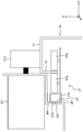
- Perspective view of the trolley and rack An enlarged view of the vicinity of the traveling portion of the traveling carriage when viewed from the X direction.
- Detailed perspective view of the traveling trolley A perspective view of the guide member of the traveling carriage and the parts associated therewith from the upper right side.
- FIG. 1 is a top view of the automated warehouse 100
- FIG. 2 is a perspective view of the traveling carriage 7 and the rack 1.
- FIG. 3 is an enlarged view of the vicinity of the traveling portion 31 of the traveling carriage 7 when viewed from the X direction.
- the left-right direction of FIG. 1 is referred to as the X direction (an example of the first direction)
- the vertical direction of FIG. 1, that is, the direction orthogonal to the X direction in the horizontal direction is the Y direction (an example of the second direction).
- the automated warehouse 100 includes a rack 1, an elevating / conveying device 3, a warehousing / delivery station 5, a plurality of traveling carriages 7, and rails 7a (an example of traveling routes).
- Rack 1 stores luggage W.
- the rack 1 has a plurality of shelves 11.
- the plurality of shelves 11 extend in the X direction and are arranged side by side at predetermined intervals in the Z direction.
- the luggage W is placed and stored on any of the plurality of shelves 11.
- each shelf 11 is provided with a relay conveyor 13.
- the relay conveyor 13 is provided in the vicinity of the elevating and transporting device 3, and the luggage W to be stored is transferred from the elevating and transporting device 3.
- the luggage W to be delivered is transferred from the traveling carriage 7.
- the rack 1 is arranged on only one side in the Y direction with respect to the traveling carriage 7 (rail 7a).
- the present invention is not limited to this, and racks 1 may be arranged on both sides in the Y direction with respect to the traveling carriage 7 (rail 7a).
- the elevating and lowering transfer device 3 is arranged between the rack 1 and the warehousing / delivery station 5 and has an elevating table.
- the elevating table can be elevated in the Z direction while supporting a plurality of loads in the elevating and conveying device 3.
- the lift has, for example, a conveyor for transferring the luggage W between the warehousing / delivery station 5 and the relay conveyor 13 of the rack 1.
- the warehousing / delivery station 5 transports the luggage W stored (warehousing) on the shelf 11 of the rack 1 from the outside to the vicinity of the lifting / lowering transport device 3. In addition, the warehousing / delivery station 5 transports the package W transported by the elevating / lowering transport device 3 for warehousing toward the outside.
- the warehousing / delivery station 5 is, for example, a transport device such as a belt conveyor.
- the rail 7a is a member provided on each shelf 11 of the rack 1 and extending in the X direction.
- the traveling carriage 7 provided on each shelf 11 travels in the X direction guided by the rail 7a provided on the corresponding shelf 11.
- the rail 7a has a traveling plane portion 71 and a movement suppressing portion 73.
- the traveling plane portion 71 is a portion parallel to the XY plane and extending in the X direction, and is a traveling plane on which the traveling carriage 7 travels.
- the movement restraining portion 73 is a portion extending in the Z direction and extending in the X direction from the end portion of the traveling plane portion 71 in the Y direction. The movement restraining portion 73 prevents the traveling carriage 7 from moving in the Y direction when the roller 27a of the traveling auxiliary roller 27 comes into contact with the roller 27a.
- the rail 7a Since the rail 7a has the above-mentioned traveling plane portion 71 and the movement suppressing portion 73, the rail 7a has a function as a traveling path of the traveling carriage 7 and a function of suppressing the movement of the traveling carriage 7 in the Y direction with respect to the rail 7a. And can be given.
- Each of the plurality of traveling trolleys 7 is a trolley capable of traveling along the X direction at a height corresponding to the height of each shelf 11.
- the traveling carriage 7 travels along the X direction by being laid at a height corresponding to each shelf 11 and being guided by a rail 7a extending in the X direction. Further, the traveling carriage 7 has a transfer device 25 (FIG. 4) for transferring the luggage W between the relay conveyor 13 of the rack 1 and the shelf 11.
- the traveling carriage 7 can convey the held luggage W in the X direction by traveling in the X direction along the shelf 11 on which the traveling carriage 7 is arranged while holding the luggage W. Further, the luggage W can be transferred between the traveling carriage 7 and the relay conveyor 13 and between the traveling carriage 7 and the shelf 11 by using the transfer device provided on the traveling carriage 7. Specifically, at the time of warehousing of the luggage W, after the luggage W transferred from the elevating transport device 3 to the relay conveyor 13 is transferred to the traveling carriage 7, the traveling carriage 7 moves in the X direction to the target position of the shelf 11. The luggage W is transferred from the traveling carriage 7 to the shelf 11 at the target position.
- the traveling carriage 7 moves along the X direction to the target position of the shelf 11, and after transferring the luggage W from the shelf 11 to the traveling carriage 7 at the target position, the traveling carriage 7 relays the conveyor. It moves along the X direction to the arrangement position of 13, and the luggage W is transferred from the traveling carriage 7 to the relay conveyor 13.
- FIG. 4 is a detailed perspective view of the traveling carriage 7.
- FIG. 5 is a perspective view of the guide member of the traveling carriage 7 and the parts and the like attached thereto as viewed from the upper right side.
- FIG. 6 is a perspective view of the guide member of the traveling carriage 7 and the parts and the like attached thereto as viewed from the upper left side.
- FIG. 7 is a perspective view of the guide member of the traveling carriage 7 and the parts and the like attached thereto as viewed from the lower left side.
- FIG. 8 is a diagram showing a definition of a surface of the guide member.
- the traveling carriage 7 includes a first guide member 21a, a second guide member 21b, a first main body portion 23a, a second main body portion 23b, a transfer device 25, and a traveling auxiliary roller 27.
- the first guide member 21a has a function of guiding the movement of the side arm 253 of the transfer device 25 and a function as a frame for determining a reference position of each component in the traveling carriage 7. It is a member having and.
- the first guide member 21a is a member that is long in one direction. As shown in FIGS. 5 to 8, the first guide member 21a has a C-shape in a cross section perpendicular to the length direction.
- the first guide member 21a has a first inner surface IP1, a second inner surface IP2, and a third inner surface IP3 as C-shaped inner surfaces.
- the first inner side surface IP1 is a plane long in the length direction of the first guide member 21a, and is a surface arranged at the lower part of the C-shape.
- the second inner surface IP2 is a surface that is long in the length direction of the first guide member 21a and is parallel to the first inner surface IP1, and is a surface that is arranged on the upper part of the C-shape.
- the third inner surface IP3 is long in the length direction of the first guide member 21a, and is a surface that forms an angle of 90 degrees with the first inner surface IP1 and the second inner surface IP2.
- the third inner surface IP3 connects the first inner surface IP1 and the second inner surface IP2.
- the first guide member 21a has a first outer surface OP1, a second outer surface OP2, and a third outer surface OP3.
- the first outer surface OP1 is a plane long in the length direction of the first guide member 21a, and is a surface arranged at the lower part of the C-shape.
- the second outer surface OP2 is a surface long in the length direction of the first guide member 21a and parallel to the first outer surface OP1, and is a surface arranged on the upper part of the C-shape.
- the third outer surface OP3 is long in the length direction of the first guide member 21a, and is a surface that forms an angle of 90 degrees with the first outer surface OP1 and the second outer surface OP2.
- the third inner surface IP3 connects the first inner surface IP1 and the second inner surface IP2.
- the rigidity of the first guide member 21a can be increased.
- the length direction of the first guide member 21a is parallel to the length direction of the rail 7a (that is, the X direction). That is, the first guide member 21a is a member extending in the X direction parallel to the rail 7a in the traveling carriage 7.
- the fact that the length direction of the first guide member 21a is parallel to the length direction of the rail 7a means that, specifically, as shown in FIG. 3, when the traveling carriage 7 is installed on the rail 7a, the first guide member 21a is first.
- the third inner surface IP3 and the third outer surface OP3 of the guide member 21a are parallel to the movement restraining portion 73 parallel to the XX plane of the rail 7a, and the first inner surface IP1 and the first guide member 21a are parallel to each other. 2 The state in which the inner surface IP2, the first outer surface OP1, and the second outer surface OP2 are parallel to the traveling plane portion 71 parallel to the XY plane of the rail 7a.
- the first guide member 21a since the first guide member 21a has a surface parallel to the rail 7a when the traveling carriage 7 is installed, the first guide member 21a can be used as a frame for determining the reference position of each component of the traveling carriage 7. ..
- the first block member 27b to which various members (traveling auxiliary roller 27, auxiliary member) of the traveling carriage 7 are attached comes into contact with the first inner surface IP1 and the third inner surface IP3. In this state, it is attached to the first guide member 21a.
- the first inner side surface IP1 is parallel to the traveling plane portion 71 of the rail 7a
- the third inner side surface IP3 is parallel to the movement suppressing portion 73 of the rail 7a. That is, in the present embodiment, the two reference surfaces when the first block member 27b is attached to the first guide member 21a are parallel to the traveling plane portion 71 and the movement suppressing portion 73 (that is, the rail 7a) of the rail 7a. It has become.
- the first connecting member 29a and the second connecting member 29b are attached to the first guide member 21a in a state of being in contact with the second outer surface OP2 and the third outer surface OP3.
- the second outer surface OP2 is parallel to the traveling plane portion 71 of the rail 7a
- the third outer surface OP3 is parallel to the movement suppressing portion 73 of the rail 7a.
- the reference surfaces for attaching the first connecting member 29a and the second connecting member 29b to the first guide member 21a are the traveling plane portion 71 and the movement restraining portion 73 (that is, the movement suppressing portion 73) of the rail 7a. It is parallel to the rail 7a).
- the first guide member 21a and the second guide member 21b have a second outer surface OP2 and a third outer surface OP3 parallel to the X direction for attaching the first connecting member 29a and the second connecting member 29b. doing.
- the cross-sectional shape of the first guide member 21a is not limited to the C shape as long as the reference surface on which the various members of the traveling carriage 7 are attached is parallel to the length direction of the rail 7a.
- the cross-sectional shape of the first guide member 21a can be L-shaped or quadrangular.
- the second guide member 21b is a member having the same configuration as the first guide member 21a described above.
- the second guide member 21b is provided apart from the first guide member 21a in the Y direction.
- the second guide member 21b is connected to the first guide member 21a by the first connecting member 29a and the second connecting member 29b.
- the first main body portion 23a constitutes the main body of the front portion of the traveling carriage 7.
- the first main body portion 23a is provided on one end side of the first guide member 21a and the second guide member 21b in the length direction.
- the side on which the first main body portion 23a is provided is defined as the front side of the traveling carriage 7.
- the first main body portion 23a includes a first connecting member 29a and a traveling portion 31.
- the first connecting member 29a connects the first guide member 21a and the second guide member 21b at the front ends of the first guide member 21a and the second guide member 21b. Specifically, as shown in FIGS. 5 and 6, the first connecting member 29a connects the first guide member 21a and the second guide member 21b inside in the Y direction. That is, the first connecting member 29a is attached in contact with the surface of the first guide member 21a and the second guide member 21b that faces the first guide member 21a or the second guide member 21b.
- the first connecting member 29a is fixed to the first guide member 21a in a state of being in contact with the third outer surface OP3 of the first guide member 21a. Further, the first connecting member 29a is fixed to the second guide member 21b in a state of being in contact with the third outer surface OP3 of the second guide member 21b. As a result, the first connecting member 29a (traveling carriage 7) can be assembled based on the guide member.
- first connecting member 29a is in contact with the horizontal plane (plane parallel to the XY plane) of the first guide member 21a and the second guide member 21b. Specifically, the first connecting member 29a is in contact with the second outer surface OP2 of the first guide member 21a. Further, the first connecting member 29a is in contact with the second outer surface OP2 of the second guide member 21b. Thereby, the position of the first connecting member 29a in the height direction can be determined with reference to the guide member.
- the reference that the first connecting member 29a is parallel to the length direction (X direction) of the rail 7a such as the second outer surface OP2 and the third outer surface OP3 of the first guide member 21a and the second guide member 21b.
- the first guide member 21a and the second guide member 21b can be made parallel.
- the first connecting member 29a is connected to the inner surfaces facing each other such as the third outer surface OP3 of the first guide member 21a and the third outer surface OP3 of the second guide member 21b, and the first guide member 21a.
- the first connecting member is attached by abutting on surfaces having the same positional relationship such as the same horizontal plane (plane parallel to the XY plane) such as the outer surface OP2 and the second outer surface OP2 of the second guide member 21b. 29a can be properly positioned.
- the traveling portion 31 is provided at the left and right (Y direction) ends of the first main body portion 23a, and causes the traveling carriage 7 to travel along the rail 7a.
- the traveling unit 31 has a drive motor 311 and wheels 313.
- the drive motor 311 is, for example, a motor fixed to a bracket BR (FIG. 3) provided on the first main body 23a.
- the bracket BR for fixing the drive motor 311 is preferably in contact with the second outer surface OP2 and the third outer surface OP3 of the first guide member 21a and the second guide member 21b. Thereby, the mounting position (position in the Y direction and the Z direction) of the drive motor 311 can be determined with reference to the guide member.
- the wheel 313 is connected to the output rotation shaft of the drive motor 311 at a position where the circumferential portion contacts the traveling plane portion 71 of the rail 7a.
- the traveling carriage 7 can travel along the traveling plane portion 71 of the rail 7a along the rail 7a.
- the second main body portion 23b is the other end of the first guide member 21a and the second guide member 21b in the length direction, that is, the side where the first main body portion 23a is provided. Is provided at the opposite end. That is, the second main body portion 23b is provided on the rear end side of the traveling carriage 7. In other words, the second main body 23b constitutes the main body at the rear of the traveling carriage 7.
- the second main body 23b has a second connecting member 29b and a driven wheel 33.
- the second connecting member 29b connects the first guide member 21a and the second guide member 21b at the rear ends of the first guide member 21a and the second guide member 21b. Specifically, as shown in FIGS. 5 and 6, the second connecting member 29b connects the first guide member 21a and the second guide member 21b inside in the Y direction. That is, the second connecting member 29b is attached in contact with the surface of the first guide member 21a and the second guide member 21b that faces the first guide member 21a or the second guide member 21b.
- the second connecting member 29b is fixed to the first guide member 21a in a state of being in contact with the third outer surface OP3 of the first guide member 21a. Further, the second connecting member 29b is fixed to the second guide member 21b in a state of being in contact with the third outer surface OP3 of the second guide member 21b. As a result, the second connecting member 29b (traveling carriage 7) can be assembled with the guide member as a reference.
- the second connecting member 29b is in contact with the horizontal plane (plane parallel to the XY plane) of the first guide member 21a and the second guide member 21b. Specifically, the second connecting member 29b is in contact with the second outer surface OP2 of the first guide member 21a. Further, the second connecting member 29b is in contact with the second outer surface OP2 of the second guide member 21b. Thereby, the position of the second connecting member 29b in the height direction can be determined with reference to these guide members.
- the second connecting member 29b is attached to the reference surfaces such as the second outer surface OP2 and the third outer surface OP3 of the first guide member 21a and the second guide member 21b.
- the guide member 21b can be parallel to each other.
- the second connecting member 29b is connected to the inner surfaces facing each other such as the third outer surface OP3 of the first guide member 21a and the third outer surface OP3 of the second guide member 21b, and the first guide member 21a.
- the second connecting member is attached by abutting on surfaces having the same positional relationship such as the same horizontal plane (plane parallel to the XY plane) such as the outer surface OP2 and the second outer surface OP2 of the second guide member 21b. 29b can be properly positioned.
- the first connecting member 29a and the second connecting member 29b have the same length, and both ends of the first guide member 21a and the second guide member 21b in the length direction. Is in contact with the second outer surface OP2 and the third outer surface OP3. As a result, the first guide member 21a and the second guide member 21b can be made parallel to each other in the X direction, the Y direction, and the Z direction.
- the traveling carriage 7 By providing the first connecting member 29a and the second connecting member 29b on the end side of the first guide member 21a and the second guide member 21b extending over the entire length of the traveling carriage 7 in the traveling direction, the traveling carriage The required number of members for accurately mounting each component of 7 can be reduced. As a result, the number of parts of the traveling carriage 7 can be reduced. This is because the first guide member 21a and the second guide member 21b can have a plurality of functions. Specifically, since most of the components of the traveling carriage 7 are provided on the first main body portion 23a or the second main body portion 23b, the first guide member 21a and the second guide member 21b to which the main body portion is fixed are provided with respect to the first main body portion 23a or the second main body portion 23b.
- first guide member 21a and the second guide member 21b can serve as guides for moving the side arm 253 (frame 251) in the X direction.
- the driven wheels 33 are provided on the left and right sides of the second connecting member 29b so as to be rotatable around the central axis at a height position where the circumferential portion contacts the traveling plane portion 71 of the rail 7a, and the rails follow the traveling of the traveling carriage 7. It rotates on the traveling plane portion 71 of 7a.
- the transfer device 25 is a device for transferring the luggage W between the traveling carriage 7 and the shelf 11 of the rack 1.
- the transfer device 25 is provided between the first main body portion 23a and the second main body portion 23b at the upper part of the first guide member 21a and the second guide member 21b in the traveling carriage 7.
- the transfer device 25 mainly includes a pair of frames 251 and a pair of side arms 253.
- one of the pair of frames 251 is omitted in order to ensure the clarity of the figure.
- the frame 251 slidably supports the side arm 253 in the Y direction by an arm rail (not shown) provided on the side surface.
- an arm rail (not shown) provided on the side surface.
- sliding members 251a that are slidable with respect to the third inner side surface IP3 (an example of the guide surface) of the first guide member 21a and the second guide member 21b, respectively. Is provided.
- the frame 251 can move in the X direction between the first main body portion 23a and the second main body portion 23b.
- the first guide member 21a has a third inner side surface IP3 parallel to the X direction that guides the frame 251 of the transfer device 25 by sliding the sliding member 251a as described above. There is.
- the sliding member 251a is the rail 7a. Can move exactly in parallel in the length direction of. That is, the frame 251 that can be moved in the X direction by the sliding member 251a can move exactly parallel to the length direction of the rail 7a. Further, since the first guide member 21a and the second guide member 21b are parallel to each other by the first connecting member 29a and the second connecting member 29b, the frame 251 is parallel to the length direction of the rail 7a. You can move smoothly.
- first portion the portion in which the frame 251 is movable is referred to as a "first portion".
- first portion the distance in the X direction between the first main body portion 23a and the frame 251 of the portions in the length direction of the first guide member 21a and the second guide member 21b is a load. It is a portion from a position that is substantially the same as the minimum width of W to a mounting position of the second main body portion 23b.
- second portion a portion outside the first portion in the length direction and provided with the first main body portion 23a and the second main body portion 23b is referred to as a "second portion”.
- the "second portion” is a portion of the first guide member 21a and the second guide member 21b in the length direction from the end portion of the guide member on the first main body portion 23a side to the first main body portion.
- the first guide member 21a and the second guide member 21b that guide the frame 251 include not only the first portion in which the frame 251 can move, but also the second portion extending in the length direction from the first portion.
- the second portion is formed by being extended from the first portion by utilizing the linearity of the first portion parallel to the length direction of the rail 7a, so that the second portion is formed in the length direction of the rail 7a. It is parallel.
- various members of the traveling carriage 7 are attached to the second part of the guide member. As a result, the various members can be attached in parallel with the length direction of the rail 7a. Further, since various members of the traveling carriage 7 can be attached to the guide member, it is possible to have a function as a member for guiding the frame 251 with respect to the guide member and a function as a frame for attaching various members.
- a ball screw 251b (FIG. 4) having a thread formed over almost the entire length direction is screwed into the frame 251.
- the frame 251 By rotating the ball screw 251b according to the rotation of a motor (not shown), for example, the frame 251 can be moved in parallel (X direction) with the length direction of the rail 7a.
- both of the pair of frames 251 may have the above-mentioned sliding member 251a and can move in the X direction, or only one of the pair of frames 251 has the above-mentioned sliding member 251a and X. It may be movable in the direction.
- the side arm 253 expands and contracts in the Y direction with respect to the frame 251 by the arm rail provided on the frame 251.
- the side arm 253 is provided with a member (not shown) that meshes with the spline of the spline member 253b extending in the X direction.
- the side arm 253 is rotated by a motor (not shown) to rotate the spline member 253b. Can be moved (expanded and contracted) in the Y direction.
- a hook 253a is rotatably provided around an axis extending in the Y direction at the end of the side arm 253 in the Y direction.
- the hook 253a rotates with respect to the side arm 253 so that its length direction is directed to the X direction, and hooks the luggage W later.
- the hook 253a is in a state where its length direction is directed to the Z direction, as shown in FIG.
- the traveling assist roller 27 suppresses the movement of the traveling carriage 7 in the Y direction when traveling along the X direction.
- the traveling auxiliary roller 27 has a pair of rollers 27a arranged at predetermined intervals in the Y direction.
- the pair of rollers 27a are rotatably attached to the shaft extending in the Z direction in the first block member 27b.
- the pair of rollers 27a sandwich the movement suppressing portion 73 of the rail 7a between them.
- one traveling assist roller 27 is fixed to the second portion on the front side of the first guide member 21a, and one is fixed to the second portion on the rear side of the first guide member 21a. A total of two will be provided.
- the traveling auxiliary roller 27 is provided on the first block member 27b. Specifically, a pair of rollers 27a are provided on the first block member 27b. Further, as shown in FIG. 3, the contact surface AP of the first block member 27b abuts and is fixed to the third inner side surface IP3 of the first guide member 21a, so that the front and rear traveling auxiliary rollers 27 are X. It will be fixed to the common third inner surface IP3 of the first guide member 21a extending in the direction.
- the front and rear traveling assistance rollers 27 are extended in the X direction and fixed to the common third inner side surface IP3 parallel to the X direction (the length direction of the rail 7a), whereby the front and rear traveling assistance rollers 27 are attached.
- the traveling trolley 7 can be accurately arranged on the traveling trolley 7 without being significantly deviated from the traveling direction (X direction) of the traveling trolley 7. Further, by attaching the traveling assist roller 27 to the first guide member 21a having the third inner side surface IP3 parallel to the rail 7a, the first guide member 21a and the rail 7a can be maintained parallel to each other.
- front and rear traveling auxiliary rollers 27 are arranged without being significantly deviated from the traveling direction of the traveling carriage 7, that is, the extending direction of the rail 7a, so that the traveling carriage 7 is parallel to the rail 7a during traveling. There will be no significant deviation in the Y direction. That is, the straightness of the traveling carriage 7 with respect to the rail 7a is improved.
- the first main body portion 23a is provided in the second portion on the front side of the first guide member 21a and the second guide member 21b, and the second main body portion 23b is provided after the first guide member 21a and the second guide member 21b.
- the provision on the second portion on the side means that the first guide member 21a and the second guide member 21b extend over the entire length of the traveling carriage 7 in the traveling direction (X direction). Therefore, one of the traveling assist rollers 27 is fixed to the second portion on the front side of the first guide member 21a, and the other one of the traveling assist rollers 27 is fixed to the second portion on the rear side of the first guide member 21a. Means that two traveling auxiliary rollers 27 are provided on both ends of the traveling carriage 7 in the traveling direction.
- the two traveling auxiliary rollers 27 are provided on the common third inner side surface IP3 of the first guide member 21a parallel to the rail 7a and on both ends of the traveling carriage 7 in the traveling direction.
- the two traveling auxiliary rollers 27 can be exactly parallel to the rail 7a over the entire length of the bogie 7.
- traveling assistance roller 27 is fixed to the first guide member 21a by the first block member 27b, the traveling assistance roller 27 can be easily attached and detached.
- the traveling carriage 7 when the traveling carriage 7 is installed on the rail 7a, the pair of rollers 27a of the traveling auxiliary rollers 27 are in a state of sandwiching the movement suppressing portion 73 of the rail 7a. Therefore, if the traveling auxiliary roller 27 is attached to the traveling carriage 7 in advance before the traveling carriage 7 is installed on the rail 7a, the traveling carriage 7 and the rail 7a need to be aligned when the traveling carriage 7 is installed on the rail 7a. It becomes difficult to sandwich the movement suppressing portion 73 between the pair of rollers 27a, and the load of the installation work increases.
- the traveling carriage 7 to which the traveling assistance roller 27 is not attached is installed on the rail 7a
- the first block member 27b to which the traveling assistance roller 27 is attached is attached to the first guide member 21a from the end of the first guide member 21a.
- the traveling auxiliary roller 27 when the traveling auxiliary roller 27 is removed from the traveling carriage 7, the traveling auxiliary roller 27 is released from the fixing of the first block member 27b to which the traveling auxiliary roller 27 is attached while the traveling carriage 7 is installed on the rail 7a, and the first guide is released.
- the traveling auxiliary roller 27 can be easily removed from the traveling carriage 7 by pulling out the first block member 27b inserted into the C-shape of the member 21a from the end of the first guide member 21a. That is, the traveling auxiliary roller 27 can be easily removed from the traveling carriage 7 without removing the traveling carriage 7 from the rail 7a.
- the first block member 27b is in contact with not only the third inner side surface IP3 but also the first inner side surface IP1 when the first guide member 21a is fixed. Thereby, the position of the traveling auxiliary roller 27 in the height direction can be determined with reference to the first guide member 21a.
- the traveling carriage 7 includes an auxiliary member.
- the auxiliary member is various members or devices used for traveling the traveling carriage 7, transferring the luggage W between the shelf 11 and the traveling carriage 7 by the transfer device 25, and the like.
- the traveling carriage 7 includes a current collecting member 41, a detecting member 43, a stopper 45, and a photoelectric device 47 as auxiliary members. In the traveling carriage 7, unnecessary members among the above auxiliary members can be omitted.
- the current collecting member 41 has an electrode that is provided on the rail 7a and abuts on a trolley member (not shown) that supplies electric power, and is a member that collects electric power supplied from the trolley member to the traveling carriage 7.
- the current collecting member 41 is fixed to the first block member 27b fixed to the second portion on the front side of the first guide member 21a. In this way, the current collecting member 41 is provided in the second portion of the first guide member 21a via the first block member 27b. This makes it easier to assemble the current collector member 41 to the traveling carriage 7. For example, by pulling out the first block member 27b from the first guide member 21a or inserting the first block member 27b into the first guide member 21a as described above, the current collecting member 41 can be easily traveled. It can be attached to and detached from the dolly 7.
- the detection member 43 detects the traveling position of the traveling carriage 7 on the rail 7a.
- the detection member 43 is, for example, a device that detects the light that has passed through the slit provided in the rail 7a and detects the position of the slit 7a in which the slit is provided.
- the detection member 43 may be a device for identifying identification information such as a barcode reader or a QR code (registered trademark) reader.
- the detection member 43 is provided in the second portion of the first guide member 21a via the first block member 27b, similarly to the current collector member 41.
- the stopper 45 abuts on, for example, a stop member (not shown) provided on the rail 7a to stop the traveling carriage 7 at a place on the rail 7a where the stop member is provided.
- the stopper 45 is provided at the front end (second portion) of the second guide member 21b via a second block member 35 fixed to the third inner side surface IP3 of the second guide member 21b. Therefore, it is provided on the second guide member 21b.
- the photoelectric device 47 is a device that irradiates light from the traveling carriage 7 to the side opposite to the front direction, that is, from the traveling carriage 7 to the outside (rear side) in the X direction.
- the photoelectric device 47 is, for example, a communication device that communicates between the traveling carriage 7 and another device, and / or a distance sensor that measures the distance between the traveling carriage 7 and another member in the X direction. Is.
- the photoelectric device 47 is attached to the first guide member 21a via the attachment member 47a.
- the mounting member 47a is fixed in contact with the first block member 27b in the second portion of the first guide member 21a. Since the first block member 27b in contact with the third inner side surface IP3 of the first guide member 21a is parallel to the X direction in which the rail 7a extends, the mounting member is in contact with and fixed to the first block member 27b. 47a is also parallel to the X direction.
- the mounting member 47a to the first guide member 21a that enables the transfer device 25 (frame 251) to move in parallel in the X direction, and further mounting the photoelectric device 47 on the mounting surface of the mounting member 47a.
- the first guide member 21a is parallel to the X direction (the length direction of the rail 7a)
- the irradiation direction of light from the photoelectric device 47 and the X direction are parallel to each other. It is possible to reduce the deviation between the light irradiation direction from the photoelectric device 47 and the X direction (the traveling direction of the traveling carriage 7).
- the auxiliary member (current collector 41, detection member 43, stopper 45, photoelectric device 47) and the traveling auxiliary roller 27 are connected to the first guide member 21a parallel to the X direction via the first block member 27b. It is fixed to the third inner surface IP3 of. That is, the first guide member 21a and the second guide member 21b have a third inner side surface IP3 parallel to the X direction for attaching the traveling auxiliary roller 27 and the auxiliary member.
- the auxiliary members (current collector 41, detection member 43, photoelectric device 47) and the traveling auxiliary roller 27 are attached to the first block member 27b.
- the auxiliary member and the traveling auxiliary roller 27 can be collectively attached to the common member with the first block member 27b, and the auxiliary member and the traveling auxiliary roller 27 can be easily attached to the first guide member 21a.
- the first block member 27b can be inserted into the C-shape from the end of the first guide member 21a, and the first block member 27b inserted inside the C-shape is the first. 1 It can be pulled out from the end of the guide member 21a.
- the auxiliary member and the traveling assistance are provided with the traveling carriage 7 installed on the rail 7a.
- the roller 27 can be easily attached to the traveling carriage 7 with a small amount of work. Further, by pulling out the first block member 27b from the end of the first guide member 21a with the traveling carriage 7 installed on the rail 7a, the auxiliary member and the traveling auxiliary roller with the traveling carriage 7 installed on the rail 7a. 27 can be easily removed from the traveling carriage 7 with a small amount of work.
- the housing of the photoelectric device 47 is brought into direct contact with either the first inner side surface IP1 to the third inner side surface IP3 or the first outer surface OP1 to the third outer surface OP3 of the first guide member 21a. May be fixed. In this case, the housing of the photoelectric device 47 becomes the mounting member 47a.
- traveling auxiliary roller 27 and / or the above-mentioned auxiliary member is attached to either the first inner side surface IP1 to the third inner side surface IP3 or the first outer surface OP1 to the third outer surface OP3 of the first guide member 21a. It may be fixed by directly contacting it.
- the traveling assistance roller 27 and the photoelectric device 47 may be individually attached to the guide member.
- the traveling auxiliary roller 27 and the photoelectric device 47 are provided at separate positions, for example, the photoelectric device 47 is attached to the end of the traveling carriage 7 so as to face outward (for example, communication provided at the end of the rail 7a).
- the traveling auxiliary roller 27 may be provided inside the traveling carriage 7.
- the traveling auxiliary roller 27 may be provided with reference to any surface of the first guide member 21a as a reference for the position of the traveling carriage 7.
- the traveling assist roller 27 is provided in a state of being in contact with the second outer surface OP2 at the lower part of the first guide member 21a and the third outer surface OP3 on the side surface. May be good.
- FIG. 9 is a diagram showing a modified example of the installed state of the traveling auxiliary roller 27 on the guide member of the traveling carriage 7.
- the traveling carriage 7 (an example of a traveling carriage) is a traveling carriage traveling on a rail 7a (an example of a traveling route) extending in the X direction (an example of the first direction), and is a traveling unit 31 (an example of a traveling unit).
- a side arm 253 (an example of a side arm), a first guide member 21a (an example of a guide member), and at least two or more traveling assist rollers 27 (an example of a traveling assist roller) are provided.
- the traveling unit 31 travels the traveling carriage 7 in the X direction.
- the side arm 253 expands and contracts in the Y direction (an example of the second direction).
- the first guide member 21a extends in the X direction and has a third inner surface IP3 (an example of a guide surface) that guides the side arm 253 in the X direction. At least two or more traveling assist rollers 27 are provided on the first guide member 21a to suppress the movement of the traveling carriage 7 in the Y direction.
- a plurality of traveling auxiliary rollers 27 are provided on the first guide member 21a extending in the same X direction as the traveling direction of the traveling carriage 7. Since the first guide member 21a extends in the traveling direction of the traveling carriage 7, by providing the first guide member 21a with a plurality of traveling assisting rollers 27, the plurality of traveling assisting rollers 27 can be moved in the traveling direction of the traveling carriage 7. Can be placed accurately along. As a result, the straightness of the traveling carriage 7 can be improved.
- the transfer device 25 is not limited to the rear hook type transfer device.
- it may be a side clamp type transfer device.
- the number of guide members provided on the traveling carriage 7 is not limited to 2 (pair). For example, only the first guide member 21a may be provided as the guide member, and the second guide member 21b may be omitted.
- the traveling auxiliary roller 27, the auxiliary member, and the photoelectric device 47 are attached to the first block member 27b in contact with the third inner side surface IP3 of the first guide member 21a. That is, the traveling auxiliary roller 27, the auxiliary member, and the photoelectric device 47 were attached to the common third inner side surface IP3 via the first block member 27b.
- a part of the above members may be attached to a surface other than the third inner side surface IP3 of the first guide member 21a as long as the surface is parallel to the length direction (X direction) of the rail 7a.
- the traveling auxiliary roller 27, the auxiliary member, and the photoelectric device 47 are attached to the common third inner surface IP3 via the first block member 27b, and are attached to the first connecting member 29a and the first connecting member 29a.
- the two connecting members 29b were attached in contact with the second outer surface OP2 and the third outer surface OP3 of the first guide member 21a and the second guide member 21b.
- a part or all of the above members may be any surface (even one surface) of the first guide member 21a. It may be attached in contact with a plurality of surfaces).
- the present invention can be widely applied to a traveling carriage traveling along a predetermined direction, particularly a traveling carriage guided by a traveling rail extending along the predetermined direction.
Abstract
A plurality of travel-assisting rollers are precisely positioned along a travel direction. A traveling platform (7) comprises a side arm (253), a first guide member (21a), and at least two or more travel-assisting rollers (27). The side arm (253) elongates and retracts in a Y direction. The first guide member (21a) extends in an X direction and has a third inside plane (IP3) for guiding the side arm (253) in the X direction. The at least two or more travel-assisting rollers (27) are provided to the guide member (21a) and suppress Y-direction movement of the traveling platform (7).
Description
本発明は、所定の方向に沿って走行する走行台車、特に、当該所定の方向に沿って延びる走行レールにガイドされて走行する走行台車、及び、当該走行台車と荷物が保管されるラックとを備える自動倉庫に関する。
The present invention includes a traveling carriage that travels along a predetermined direction, particularly a traveling carriage that travels guided by a traveling rail extending along the predetermined direction, and a rack that stores the traveling carriage and luggage. Regarding automated warehouses to prepare.
従来、高さ方向に複数段設けられた棚のそれぞれに対して設けられ、自身が設けられた棚の長さ方向に沿って走行する走行台車が知られている。この走行台車は、自身が設けられた棚の長さ方向に沿って延びる走行レールにガイドされることで、棚の長さ方向に沿って走行する。また、この走行台車には、走行台車の走行の補助をする一対の走行補助ローラが、走行レールの長さ方向に並んで設けられる(例えば、特許文献1)。
Conventionally, there is known a traveling carriage that is provided for each of the shelves provided in a plurality of stages in the height direction and travels along the length direction of the shelves provided. The traveling carriage travels along the length direction of the shelf by being guided by a traveling rail extending along the length direction of the shelf provided with the traveling carriage. Further, the traveling bogie is provided with a pair of traveling assist rollers that assist the traveling of the traveling carriage side by side in the length direction of the traveling rail (for example, Patent Document 1).
従来の走行台車においては、走行方向の前側に設けられた前フレームに一対の走行補助ローラのうちの一方が取り付けられ、走行方向の後側に設けられた後フレームに他方の走行補助ローラが取り付けられている。また、前フレームと後フレームとは、走行台車の走行方向に延びる一対の部材により連結されている。
In a conventional traveling bogie, one of a pair of traveling assist rollers is attached to a front frame provided on the front side in the traveling direction, and the other traveling assist roller is attached to a rear frame provided on the rear side in the traveling direction. Has been done. Further, the front frame and the rear frame are connected by a pair of members extending in the traveling direction of the traveling carriage.
このような構成の走行台車では、前フレームと後フレームとを連結する部材の加工誤差、前フレームと後フレームを連結する際の据付誤差、走行台車の他の構成部品の加工誤差、及び/又は、当該他の構成部品の据付誤差等により、前フレームと後フレームとが正確に平行に並んで配置されないことがある。その結果、前フレームに設けられた走行補助ローラと後フレームに設けられた走行補助ローラとが、精度よく走行方向に平行に並んで配置されないことがある。
走行補助ローラが走行方向に正確に平行に配置されていないと、走行台車が走行レールに対して適切に配置されなくなるので、走行台車が走行レールに沿って適切に走行できなくなる。 In a traveling bogie with such a configuration, a machining error of a member connecting the front frame and the rear frame, an installation error when connecting the front frame and the rear frame, a machining error of other components of the traveling bogie, and / or , The front frame and the rear frame may not be arranged exactly in parallel due to installation errors of the other components. As a result, the traveling assist rollers provided on the front frame and the traveling assist rollers provided on the rear frame may not be accurately arranged side by side in parallel in the traveling direction.
If the traveling auxiliary rollers are not arranged exactly parallel to the traveling direction, the traveling bogie will not be properly arranged with respect to the traveling rail, and the traveling bogie will not be able to travel appropriately along the traveling rail.
本発明の目的は、所定の走行方向に沿って走行し、当該走行方向に並んで配置される複数の走行補助ローラを備える走行台車において、複数の走行補助ローラを走行方向に沿って精度よく配置することにある。
An object of the present invention is to accurately arrange a plurality of traveling auxiliary rollers along a traveling direction in a traveling carriage provided with a plurality of traveling assisting rollers that travel along a predetermined traveling direction and are arranged side by side in the traveling direction. To do.
以下に、課題を解決するための手段として複数の態様を説明する。これら態様は、必要に応じて任意に組み合せることができる。
本発明の一見地に係る走行台車は、第1方向に延在する走行経路を走行する走行台車である。走行台車は、サイドアームと、ガイド部材と、少なくとも2以上の走行補助ローラと、を備える。
サイドアームは、第2方向に伸縮する。第2方向は、水平方向において第1方向に直交する方向である。
ガイド部材は、第1方向に延在し、サイドアームを第1方向にガイドするガイド面を有する。
少なくとも2以上の走行補助ローラは、ガイド部材に設けられ、走行台車の第2方向への移動を抑制する。 Hereinafter, a plurality of aspects will be described as means for solving the problem. These aspects can be arbitrarily combined as needed.
The traveling trolley according to the first aspect of the present invention is a traveling trolley that travels on a traveling route extending in the first direction. The traveling carriage includes a side arm, a guide member, and at least two or more traveling assist rollers.
The side arm expands and contracts in the second direction. The second direction is a direction orthogonal to the first direction in the horizontal direction.
The guide member extends in the first direction and has a guide surface that guides the side arm in the first direction.
At least two or more traveling assist rollers are provided on the guide member to suppress the movement of the traveling carriage in the second direction.
上記の走行台車においては、複数の走行補助ローラが、走行台車の走行方向と同じ第1方向に延在するガイド部材に設けられる。ガイド部材は第1方向、すなわち、走行台車の走行方向に延在しているので、当該ガイド部材に複数の走行補助ローラを設けることで、複数の走行補助ローラを走行台車の走行方向に沿って精度よく配置できる。その結果、走行台車の直進性を向上できる。
In the above traveling carriage, a plurality of traveling auxiliary rollers are provided on the guide member extending in the same first direction as the traveling direction of the traveling carriage. Since the guide member extends in the first direction, that is, in the traveling direction of the traveling carriage, by providing the guide member with a plurality of traveling assist rollers, a plurality of traveling assisting rollers can be provided along the traveling direction of the traveling carriage. Can be placed accurately. As a result, the straightness of the traveling carriage can be improved.
ガイド部材は、第1方向における走行台車の全長に亘って設けられてもよい。また、ガイド部材は、サイドアームをガイドする第1部分と、第1方向において第1部分よりも外側に位置する第2部分と、を有してもよい。この場合に、走行補助ローラは、ガイド部材の第2部分に設けられてもよい。
走行補助ローラをガイド部材の第2部分に設けることで、走行補助ローラを走行台車の第1方向の全長の端部に設けることができるので、走行台車の第1方向の全長に亘って走行方向に対して平行に走行補助ローラを配置できる。その結果、走行台車の直進性を向上できる。 The guide member may be provided over the entire length of the traveling carriage in the first direction. Further, the guide member may have a first portion for guiding the side arm and a second portion located outside the first portion in the first direction. In this case, the traveling auxiliary roller may be provided on the second portion of the guide member.
By providing the traveling assistance roller in the second portion of the guide member, the traveling assistance roller can be provided at the end of the entire length of the traveling carriage in the first direction, so that the traveling direction can be extended over the entire length of the traveling carriage in the first direction. The traveling auxiliary roller can be arranged in parallel with the vehicle. As a result, the straightness of the traveling carriage can be improved.
走行台車において、ガイド部材は第2方向に離間して一対設けられてもよい。この場合、走行台車は、第1連結部材と第2連結部材とをさらに備えてもよい。第1連結部材と第2連結部材は、一対のガイド部材における第1方向の端部側において、一対のガイド部材をガイド部材の第2方向の内側で連結する。
これにより、ガイド部材をサイドアームを第1方向にガイドする部材としつつ、ガイド部材を基準に走行台車を組み付けることができる。すなわち、ガイド部材に、サイドアームをガイドする機能と、走行台車のフレームとしての機能とを持たせることができる。その結果、走行台車の部品点数を少なくできる。 In the traveling carriage, a pair of guide members may be provided so as to be separated from each other in the second direction. In this case, the traveling carriage may further include a first connecting member and a second connecting member. The first connecting member and the second connecting member connect the pair of guide members inside the guide member in the second direction on the end side of the pair of guide members in the first direction.
As a result, the traveling carriage can be assembled with the guide member as a reference while using the guide member as a member for guiding the side arm in the first direction. That is, the guide member can have a function of guiding the side arm and a function as a frame of the traveling carriage. As a result, the number of parts of the traveling carriage can be reduced.
走行台車は、ガイド部材に設けられた補助部材をさらに備えてもよい。補助部材は、走行台車への給電のための集電部材、走行台車の走行位置を検出する検出部材、走行台車を停止させるストッパ、又は、第1方向に対して外側に向けて光を照射する光電装置のうちの少なくとも1つであってもよい。
このように、ガイド部材を基準に走行台車の走行を補助するための補助部材を設けることで、補助部材を走行台車に組み付けやすくなる。 The traveling carriage may further include an auxiliary member provided on the guide member. The auxiliary member is a current collecting member for supplying power to the traveling carriage, a detecting member for detecting the traveling position of the traveling carriage, a stopper for stopping the traveling carriage, or irradiating light outward with respect to the first direction. It may be at least one of the photoelectric devices.
In this way, by providing the auxiliary member for assisting the traveling of the traveling carriage with the guide member as a reference, it becomes easy to assemble the auxiliary member to the traveling carriage.
光電装置は、前記第1方向に対して外側に向けて前記光を照射するようガイド部材に当接した取付部材の取付面に取り付けられてもよい。これにより、ガイド部材が第1方向に平行であることを利用して、光電装置からの光の照射方向と第1方向とを平行に近づけて、光電装置からの光の照射方向と第1方向とのずれを小さくできる。
The photoelectric device may be mounted on the mounting surface of the mounting member that is in contact with the guide member so as to irradiate the light outward with respect to the first direction. As a result, by utilizing the fact that the guide member is parallel to the first direction, the light irradiation direction from the photoelectric device and the first direction are brought close to parallel, and the light irradiation direction from the photoelectric device and the first direction are brought closer to each other. The deviation from and can be reduced.
走行台車は、ブロック部材をさらに備えてもよい。ブロック部材は、ガイド部材に形成される空間に挿入された状態でガイド部材に固定される。ブロック部材には、走行補助ローラと補助部材の少なくとも1つが取り付けられる。
これにより、共通のブロック部材に走行補助ローラ及び/又は補助部材をまとめて取り付けて、走行補助ローラ及び/又は補助部材をガイド部材に容易に取り付けることができる。 The traveling carriage may further include a block member. The block member is fixed to the guide member in a state of being inserted into the space formed in the guide member. At least one of the traveling auxiliary roller and the auxiliary member is attached to the block member.
Thereby, the traveling auxiliary roller and / or the auxiliary member can be collectively attached to the common block member, and the traveling auxiliary roller and / or the auxiliary member can be easily attached to the guide member.
走行経路は、走行平面部分と、移動抑制部分と、を有してもよい。走行平面部分は、走行台車の走行平面となる部分である。移動抑制部分は、走行平面部分から第3方向に延びる部分であって、走行補助ローラが当接することで走行台車の第2方向への移動を抑制する。第3方向は、第1方向及び第2方向に直交する方向である。
これにより、走行経路に対して、走行台車の走行経路としての機能と、走行台車の第2方向への移動を抑制する機能と、を持たせることができる。 The traveling path may include a traveling plane portion and a movement restraining portion. The traveling plane portion is a portion serving as a traveling plane of the traveling carriage. The movement restraining portion is a portion extending in the third direction from the traveling plane portion, and the traveling auxiliary roller abuts on the portion to suppress the movement of the traveling carriage in the second direction. The third direction is a direction orthogonal to the first direction and the second direction.
As a result, the traveling route can be provided with a function as a traveling route of the traveling carriage and a function of suppressing the movement of the traveling carriage in the second direction.
走行補助ローラは、一対のローラを有してもよい。一対のローラは、第2方向に所定の間隔を空けて配置される。また、移動抑制部分は一対のローラの間に挟み込まれる。これにより、走行台車の第2方向への移動をより抑制できる。
The traveling auxiliary roller may have a pair of rollers. The pair of rollers are arranged in the second direction at predetermined intervals. Further, the movement restraining portion is sandwiched between the pair of rollers. As a result, the movement of the traveling carriage in the second direction can be further suppressed.
ガイド部材の断面はC字形状、L字形状、又は四角形状のいずれかを有してもよい。これにより、ガイド部材の剛性を高くできる。
The cross section of the guide member may have either a C-shape, an L-shape, or a square shape. As a result, the rigidity of the guide member can be increased.
ブロック部材は、ガイド部材に挿入された状態から、第1方向に前記ガイド部材の端部から引き抜き可能であってもよい。また、ブロック部材は、ガイド部材の端部から第1方向に挿入することでガイド部材に挿入可能であってもよい。
これにより、走行台車を走行経路に据え付けた状態で、走行補助ローラ及び/又は補助部材をガイド部材に容易に脱着できる。 The block member may be able to be pulled out from the end portion of the guide member in the first direction from the state of being inserted into the guide member. Further, the block member may be inserted into the guide member by inserting the block member in the first direction from the end portion of the guide member.
As a result, the traveling auxiliary roller and / or the auxiliary member can be easily attached to and detached from the guide member while the traveling carriage is installed on the traveling path.
本発明の他の見地に係る自動倉庫は、上記の走行台車と、当該走行台車から移載された荷物、及び/又は、当該走行台車に移載する荷物を保管するラックと、を備える。
The automated warehouse according to another aspect of the present invention includes the above-mentioned traveling carriage, luggage transferred from the traveling carriage, and / or a rack for storing luggage transferred to the traveling carriage.
走行台車の走行方向に平行なガイド部材に複数の走行補助ローラを設けることで、複数の走行補助ローラを走行台車の走行方向に沿って精度よく配置できる。その結果、走行台車の第1方向への直進性を向上できる。
By providing a plurality of traveling auxiliary rollers on the guide member parallel to the traveling direction of the traveling carriage, the plurality of traveling auxiliary rollers can be accurately arranged along the traveling direction of the traveling carriage. As a result, the straightness of the traveling carriage in the first direction can be improved.
1.第1実施形態
(1)自動倉庫
以下、図1~図3を用いて、第1実施形態に係る走行台車7が設けられる自動倉庫100を説明する。図1は自動倉庫100の上面図、図2は走行台車7とラック1の斜視図を示す図である。図3は、走行台車7の走行部31近傍をX方向から見たときの拡大図である。以下の説明では、図1の左右方向をX方向(第1方向の一例)といい、図1の上下方向、すなわち、X方向と水平方向において直交する方向をY方向(第2方向の一例)といい、X方向及びY方向に垂直である図2の上下方向をZ方向(第3方向の一例)という。
自動倉庫100は、ラック1と、昇降搬送装置3と、入出庫ステーション5と、複数の走行台車7と、レール7a(走行経路の一例)と、を備える。 1. 1. First Embodiment (1) Automated Warehouse Hereinafter, theautomated warehouse 100 provided with the traveling carriage 7 according to the first embodiment will be described with reference to FIGS. 1 to 3. FIG. 1 is a top view of the automated warehouse 100, and FIG. 2 is a perspective view of the traveling carriage 7 and the rack 1. FIG. 3 is an enlarged view of the vicinity of the traveling portion 31 of the traveling carriage 7 when viewed from the X direction. In the following description, the left-right direction of FIG. 1 is referred to as the X direction (an example of the first direction), and the vertical direction of FIG. 1, that is, the direction orthogonal to the X direction in the horizontal direction is the Y direction (an example of the second direction). The vertical direction of FIG. 2, which is perpendicular to the X and Y directions, is referred to as the Z direction (an example of the third direction).
Theautomated warehouse 100 includes a rack 1, an elevating / conveying device 3, a warehousing / delivery station 5, a plurality of traveling carriages 7, and rails 7a (an example of traveling routes).
(1)自動倉庫
以下、図1~図3を用いて、第1実施形態に係る走行台車7が設けられる自動倉庫100を説明する。図1は自動倉庫100の上面図、図2は走行台車7とラック1の斜視図を示す図である。図3は、走行台車7の走行部31近傍をX方向から見たときの拡大図である。以下の説明では、図1の左右方向をX方向(第1方向の一例)といい、図1の上下方向、すなわち、X方向と水平方向において直交する方向をY方向(第2方向の一例)といい、X方向及びY方向に垂直である図2の上下方向をZ方向(第3方向の一例)という。
自動倉庫100は、ラック1と、昇降搬送装置3と、入出庫ステーション5と、複数の走行台車7と、レール7a(走行経路の一例)と、を備える。 1. 1. First Embodiment (1) Automated Warehouse Hereinafter, the
The
ラック1は、荷物Wを保管する。具体的には、ラック1は、複数の棚11を有する。複数の棚11は、X方向に延在し、Z方向に所定の間隔を空けて並んで配置される。荷物Wは、複数の棚11のいずれかに載置されて保管される。
また、各棚11には、中継コンベヤ13が設けられる。中継コンベヤ13は、昇降搬送装置3の近傍に設けられ、入庫する荷物Wが昇降搬送装置3から移載される。また、出庫する荷物Wが走行台車7から移載される。 Rack 1 stores luggage W. Specifically, the rack 1 has a plurality ofshelves 11. The plurality of shelves 11 extend in the X direction and are arranged side by side at predetermined intervals in the Z direction. The luggage W is placed and stored on any of the plurality of shelves 11.
Further, eachshelf 11 is provided with a relay conveyor 13. The relay conveyor 13 is provided in the vicinity of the elevating and transporting device 3, and the luggage W to be stored is transferred from the elevating and transporting device 3. In addition, the luggage W to be delivered is transferred from the traveling carriage 7.
また、各棚11には、中継コンベヤ13が設けられる。中継コンベヤ13は、昇降搬送装置3の近傍に設けられ、入庫する荷物Wが昇降搬送装置3から移載される。また、出庫する荷物Wが走行台車7から移載される。 Rack 1 stores luggage W. Specifically, the rack 1 has a plurality of
Further, each
本実施形態においては、図1に示すように、ラック1は、走行台車7(レール7a)に対してY方向の片側のみに配置されている。しかし、これに限られず、走行台車7(レール7a)に対してY方向の両側にラック1を配置してもよい。
In the present embodiment, as shown in FIG. 1, the rack 1 is arranged on only one side in the Y direction with respect to the traveling carriage 7 (rail 7a). However, the present invention is not limited to this, and racks 1 may be arranged on both sides in the Y direction with respect to the traveling carriage 7 (rail 7a).
昇降搬送装置3は、ラック1と入出庫ステーション5との間に配置され、昇降台を有する。昇降台は、昇降搬送装置3において、複数の荷物を支持した状態でZ方向に昇降可能となっている。昇降台は、例えば、入出庫ステーション5、ラック1の中継コンベヤ13との間で荷物Wを移載するコンベヤを有している。
The elevating and lowering transfer device 3 is arranged between the rack 1 and the warehousing / delivery station 5 and has an elevating table. The elevating table can be elevated in the Z direction while supporting a plurality of loads in the elevating and conveying device 3. The lift has, for example, a conveyor for transferring the luggage W between the warehousing / delivery station 5 and the relay conveyor 13 of the rack 1.
入出庫ステーション5は、ラック1の棚11に保管(入庫)する荷物Wを外部から昇降搬送装置3の近傍まで搬送する。また、入出庫ステーション5は、出庫のために昇降搬送装置3にて搬送された荷物Wを外部に向けて搬送する。入出庫ステーション5は、例えば、ベルトコンベヤーなどの搬送装置である。
The warehousing / delivery station 5 transports the luggage W stored (warehousing) on the shelf 11 of the rack 1 from the outside to the vicinity of the lifting / lowering transport device 3. In addition, the warehousing / delivery station 5 transports the package W transported by the elevating / lowering transport device 3 for warehousing toward the outside. The warehousing / delivery station 5 is, for example, a transport device such as a belt conveyor.
レール7aは、ラック1の各棚11に設けられ、X方向に延在する部材である。各棚11に設けられた走行台車7は、対応する棚11に設けられたレール7aにガイドされてX方向に走行する。図3に示すように、レール7aは、走行平面部分71と、移動抑制部分73と、を有する。
走行平面部分71は、X-Y平面に平行でありX方向に延在する部分であって、走行台車7が走行する走行平面となる。移動抑制部分73は、走行平面部分71のY方向の端部からZ方向に延び、かつ、X方向に延在する部分である。移動抑制部分73は、走行補助ローラ27のローラ27aが当接して、走行台車7がY方向に移動することを抑制する。 Therail 7a is a member provided on each shelf 11 of the rack 1 and extending in the X direction. The traveling carriage 7 provided on each shelf 11 travels in the X direction guided by the rail 7a provided on the corresponding shelf 11. As shown in FIG. 3, the rail 7a has a traveling plane portion 71 and a movement suppressing portion 73.
The travelingplane portion 71 is a portion parallel to the XY plane and extending in the X direction, and is a traveling plane on which the traveling carriage 7 travels. The movement restraining portion 73 is a portion extending in the Z direction and extending in the X direction from the end portion of the traveling plane portion 71 in the Y direction. The movement restraining portion 73 prevents the traveling carriage 7 from moving in the Y direction when the roller 27a of the traveling auxiliary roller 27 comes into contact with the roller 27a.
走行平面部分71は、X-Y平面に平行でありX方向に延在する部分であって、走行台車7が走行する走行平面となる。移動抑制部分73は、走行平面部分71のY方向の端部からZ方向に延び、かつ、X方向に延在する部分である。移動抑制部分73は、走行補助ローラ27のローラ27aが当接して、走行台車7がY方向に移動することを抑制する。 The
The traveling
レール7aが上記の走行平面部分71と移動抑制部分73とを有することにより、レール7aに対して、走行台車7の走行経路としての機能と、走行台車7のY方向への移動を抑制する機能と、を持たせることができる。
Since the rail 7a has the above-mentioned traveling plane portion 71 and the movement suppressing portion 73, the rail 7a has a function as a traveling path of the traveling carriage 7 and a function of suppressing the movement of the traveling carriage 7 in the Y direction with respect to the rail 7a. And can be given.
(2)走行台車
(2-1)走行台車の概略説明
複数の走行台車7は、それぞれ、各棚11の高さに対応する高さにおいてX方向に沿って走行可能な台車である。走行台車7は、各棚11に対応する高さに敷設されX方向に延びるレール7aにガイドされて走行することで、X方向に沿って走行する。また、走行台車7は、ラック1の中継コンベヤ13との間、及び、棚11との間で荷物Wを移載する移載装置25(図4)を有している。 (2) Traveling trolley (2-1) Outline of traveling trolley Each of the plurality of travelingtrolleys 7 is a trolley capable of traveling along the X direction at a height corresponding to the height of each shelf 11. The traveling carriage 7 travels along the X direction by being laid at a height corresponding to each shelf 11 and being guided by a rail 7a extending in the X direction. Further, the traveling carriage 7 has a transfer device 25 (FIG. 4) for transferring the luggage W between the relay conveyor 13 of the rack 1 and the shelf 11.
(2-1)走行台車の概略説明
複数の走行台車7は、それぞれ、各棚11の高さに対応する高さにおいてX方向に沿って走行可能な台車である。走行台車7は、各棚11に対応する高さに敷設されX方向に延びるレール7aにガイドされて走行することで、X方向に沿って走行する。また、走行台車7は、ラック1の中継コンベヤ13との間、及び、棚11との間で荷物Wを移載する移載装置25(図4)を有している。 (2) Traveling trolley (2-1) Outline of traveling trolley Each of the plurality of traveling
上記の構成により、走行台車7は、荷物Wを保持した状態で自身が配置された棚11に沿ってX方向に走行することで、保持した荷物WをX方向に搬送できる。また、走行台車7に設けられた移載装置を用いて、走行台車7と中継コンベヤ13との間、及び、走行台車7と棚11との間で荷物Wを移載できる。
具体的には、荷物Wの入庫時には、昇降搬送装置3から中継コンベヤ13に移載された荷物Wを走行台車7へと移載した後、走行台車7が棚11の目的位置までX方向に沿って移動し、当該目的位置にて走行台車7から棚11へと荷物Wが移載される。
一方、出庫時には、走行台車7が棚11の目的位置までX方向に沿って移動し、当該目的位置にて棚11から走行台車7へと荷物Wを移載した後、走行台車7が中継コンベヤ13の配置位置までX方向に沿って移動し、走行台車7から中継コンベヤ13へと荷物Wが移載される。 With the above configuration, the travelingcarriage 7 can convey the held luggage W in the X direction by traveling in the X direction along the shelf 11 on which the traveling carriage 7 is arranged while holding the luggage W. Further, the luggage W can be transferred between the traveling carriage 7 and the relay conveyor 13 and between the traveling carriage 7 and the shelf 11 by using the transfer device provided on the traveling carriage 7.
Specifically, at the time of warehousing of the luggage W, after the luggage W transferred from the elevatingtransport device 3 to the relay conveyor 13 is transferred to the traveling carriage 7, the traveling carriage 7 moves in the X direction to the target position of the shelf 11. The luggage W is transferred from the traveling carriage 7 to the shelf 11 at the target position.
On the other hand, at the time of warehousing, the travelingcarriage 7 moves along the X direction to the target position of the shelf 11, and after transferring the luggage W from the shelf 11 to the traveling carriage 7 at the target position, the traveling carriage 7 relays the conveyor. It moves along the X direction to the arrangement position of 13, and the luggage W is transferred from the traveling carriage 7 to the relay conveyor 13.
具体的には、荷物Wの入庫時には、昇降搬送装置3から中継コンベヤ13に移載された荷物Wを走行台車7へと移載した後、走行台車7が棚11の目的位置までX方向に沿って移動し、当該目的位置にて走行台車7から棚11へと荷物Wが移載される。
一方、出庫時には、走行台車7が棚11の目的位置までX方向に沿って移動し、当該目的位置にて棚11から走行台車7へと荷物Wを移載した後、走行台車7が中継コンベヤ13の配置位置までX方向に沿って移動し、走行台車7から中継コンベヤ13へと荷物Wが移載される。 With the above configuration, the traveling
Specifically, at the time of warehousing of the luggage W, after the luggage W transferred from the elevating
On the other hand, at the time of warehousing, the traveling
(2-2)走行台車の詳細説明
以下、図3~図8を用いて、第1実施形態に係る走行台車7の構成を詳細に説明する。図4は、走行台車7の詳細斜視図である。図5は、走行台車7のガイド部材とそれに付随する部品等を右上側から見た斜視図である。図6は、走行台車7のガイド部材とそれに付随する部品等を左上側から見た斜視図である。図7は、走行台車7のガイド部材とそれに付随する部品等を左下側から見た斜視図である。図8は、ガイド部材が有する面の定義を示す図である。
走行台車7は、第1ガイド部材21aと、第2ガイド部材21bと、第1本体部23aと、第2本体部23bと、移載装置25と、走行補助ローラ27と、を備える。 (2-2) Detailed Description of Traveling Vehicle The configuration of the travelingvehicle 7 according to the first embodiment will be described in detail below with reference to FIGS. 3 to 8. FIG. 4 is a detailed perspective view of the traveling carriage 7. FIG. 5 is a perspective view of the guide member of the traveling carriage 7 and the parts and the like attached thereto as viewed from the upper right side. FIG. 6 is a perspective view of the guide member of the traveling carriage 7 and the parts and the like attached thereto as viewed from the upper left side. FIG. 7 is a perspective view of the guide member of the traveling carriage 7 and the parts and the like attached thereto as viewed from the lower left side. FIG. 8 is a diagram showing a definition of a surface of the guide member.
The travelingcarriage 7 includes a first guide member 21a, a second guide member 21b, a first main body portion 23a, a second main body portion 23b, a transfer device 25, and a traveling auxiliary roller 27.
以下、図3~図8を用いて、第1実施形態に係る走行台車7の構成を詳細に説明する。図4は、走行台車7の詳細斜視図である。図5は、走行台車7のガイド部材とそれに付随する部品等を右上側から見た斜視図である。図6は、走行台車7のガイド部材とそれに付随する部品等を左上側から見た斜視図である。図7は、走行台車7のガイド部材とそれに付随する部品等を左下側から見た斜視図である。図8は、ガイド部材が有する面の定義を示す図である。
走行台車7は、第1ガイド部材21aと、第2ガイド部材21bと、第1本体部23aと、第2本体部23bと、移載装置25と、走行補助ローラ27と、を備える。 (2-2) Detailed Description of Traveling Vehicle The configuration of the traveling
The traveling
(2-2-1)ガイド部材
第1ガイド部材21aは、走行台車7においては、移載装置25のサイドアーム253の移動をガイドする機能と、各構成要素の基準位置を定めるフレームとしての機能とを有する部材である。
第1ガイド部材21aは、一方向に長い部材である。図5~図8に示すように、第1ガイド部材21aは、長さ方向とは垂直な断面においてはC字形状を有している。 (2-2-1) Guide member Thefirst guide member 21a has a function of guiding the movement of the side arm 253 of the transfer device 25 and a function as a frame for determining a reference position of each component in the traveling carriage 7. It is a member having and.
Thefirst guide member 21a is a member that is long in one direction. As shown in FIGS. 5 to 8, the first guide member 21a has a C-shape in a cross section perpendicular to the length direction.
第1ガイド部材21aは、走行台車7においては、移載装置25のサイドアーム253の移動をガイドする機能と、各構成要素の基準位置を定めるフレームとしての機能とを有する部材である。
第1ガイド部材21aは、一方向に長い部材である。図5~図8に示すように、第1ガイド部材21aは、長さ方向とは垂直な断面においてはC字形状を有している。 (2-2-1) Guide member The
The
具体的には、第1ガイド部材21aは、図8に示すように、C字形状の内側の面として、第1内側面IP1と、第2内側面IP2と、第3内側面IP3と、を有する。第1内側面IP1は、第1ガイド部材21aの長さ方向に長い平面であり、C字形状の下部に配置される面である。第2内側面IP2は、第1ガイド部材21aの長さ方向に長く第1内側面IP1と平行な面であり、C字形状の上部に配置される面である。第3内側面IP3は、第1ガイド部材21aの長さ方向に長く、第1内側面IP1及び第2内側面IP2とは90度の角度をなす面である。第3内側面IP3は、第1内側面IP1と第2内側面IP2とを接続する。
Specifically, as shown in FIG. 8, the first guide member 21a has a first inner surface IP1, a second inner surface IP2, and a third inner surface IP3 as C-shaped inner surfaces. Have. The first inner side surface IP1 is a plane long in the length direction of the first guide member 21a, and is a surface arranged at the lower part of the C-shape. The second inner surface IP2 is a surface that is long in the length direction of the first guide member 21a and is parallel to the first inner surface IP1, and is a surface that is arranged on the upper part of the C-shape. The third inner surface IP3 is long in the length direction of the first guide member 21a, and is a surface that forms an angle of 90 degrees with the first inner surface IP1 and the second inner surface IP2. The third inner surface IP3 connects the first inner surface IP1 and the second inner surface IP2.
一方、C字形状の外側の面として、第1ガイド部材21aは、第1外側面OP1と、第2外側面OP2と、第3外側面OP3と、を有する。第1外側面OP1は、第1ガイド部材21aの長さ方向に長い平面であり、C字形状の下部に配置される面である。第2外側面OP2は、第1ガイド部材21aの長さ方向に長く第1外側面OP1と平行な面であり、C字形状の上部に配置される面である。第3外側面OP3は、第1ガイド部材21aの長さ方向に長く、第1外側面OP1及び第2外側面OP2とは90度の角度をなす面である。第3内側面IP3は、第1内側面IP1と第2内側面IP2とを接続する。
On the other hand, as the C-shaped outer surface, the first guide member 21a has a first outer surface OP1, a second outer surface OP2, and a third outer surface OP3. The first outer surface OP1 is a plane long in the length direction of the first guide member 21a, and is a surface arranged at the lower part of the C-shape. The second outer surface OP2 is a surface long in the length direction of the first guide member 21a and parallel to the first outer surface OP1, and is a surface arranged on the upper part of the C-shape. The third outer surface OP3 is long in the length direction of the first guide member 21a, and is a surface that forms an angle of 90 degrees with the first outer surface OP1 and the second outer surface OP2. The third inner surface IP3 connects the first inner surface IP1 and the second inner surface IP2.
第1ガイド部材21aの断面を上記のようにC字形状とすることで、第1ガイド部材21aの剛性を高くできる。
By making the cross section of the first guide member 21a C-shaped as described above, the rigidity of the first guide member 21a can be increased.
走行台車7がレール7aに据え付けられたとき、第1ガイド部材21aの長さ方向は、レール7aの長さ方向(すなわち、X方向)と平行となる。すなわち、第1ガイド部材21aは、走行台車7において、レール7aと平行なX方向に延在する部材となる。
第1ガイド部材21aの長さ方向がレール7aの長さ方向と平行であるとは、具体的には、図3に示すように、走行台車7がレール7aに据え付けられたときに、第1ガイド部材21aの第3内側面IP3及び第3外側面OP3がレール7aのX-Z平面に平行な移動抑制部分73と平行となっており、第1ガイド部材21aの第1内側面IP1、第2内側面IP2、第1外側面OP1、及び第2外側面OP2がレール7aのX-Y平面に平行な走行平面部分71と平行となっている状態をいう。 When the travelingcarriage 7 is installed on the rail 7a, the length direction of the first guide member 21a is parallel to the length direction of the rail 7a (that is, the X direction). That is, the first guide member 21a is a member extending in the X direction parallel to the rail 7a in the traveling carriage 7.
The fact that the length direction of thefirst guide member 21a is parallel to the length direction of the rail 7a means that, specifically, as shown in FIG. 3, when the traveling carriage 7 is installed on the rail 7a, the first guide member 21a is first. The third inner surface IP3 and the third outer surface OP3 of the guide member 21a are parallel to the movement restraining portion 73 parallel to the XX plane of the rail 7a, and the first inner surface IP1 and the first guide member 21a are parallel to each other. 2 The state in which the inner surface IP2, the first outer surface OP1, and the second outer surface OP2 are parallel to the traveling plane portion 71 parallel to the XY plane of the rail 7a.
第1ガイド部材21aの長さ方向がレール7aの長さ方向と平行であるとは、具体的には、図3に示すように、走行台車7がレール7aに据え付けられたときに、第1ガイド部材21aの第3内側面IP3及び第3外側面OP3がレール7aのX-Z平面に平行な移動抑制部分73と平行となっており、第1ガイド部材21aの第1内側面IP1、第2内側面IP2、第1外側面OP1、及び第2外側面OP2がレール7aのX-Y平面に平行な走行平面部分71と平行となっている状態をいう。 When the traveling
The fact that the length direction of the
このように、第1ガイド部材21aが走行台車7の据え付け時にレール7aと平行な面を有しているので、第1ガイド部材21aを走行台車7の各構成要素の基準位置を定めるフレームとできる。
As described above, since the first guide member 21a has a surface parallel to the rail 7a when the traveling carriage 7 is installed, the first guide member 21a can be used as a frame for determining the reference position of each component of the traveling carriage 7. ..
具体的には、後述するように、走行台車7の各種部材(走行補助ローラ27、補助部材)が取り付けられる第1ブロック部材27bは、第1内側面IP1と第3内側面IP3と当接した状態で、第1ガイド部材21aに取り付けられる。また、上記のように、第1内側面IP1はレール7aの走行平面部分71と平行であり、第3内側面IP3はレール7aの移動抑制部分73と平行である。すなわち、本実施形態においては、第1ブロック部材27bを第1ガイド部材21aに取り付ける際の基準となる2面が、レール7aの走行平面部分71及び移動抑制部分73(つまり、レール7a)と平行となっている。
Specifically, as will be described later, the first block member 27b to which various members (traveling auxiliary roller 27, auxiliary member) of the traveling carriage 7 are attached comes into contact with the first inner surface IP1 and the third inner surface IP3. In this state, it is attached to the first guide member 21a. Further, as described above, the first inner side surface IP1 is parallel to the traveling plane portion 71 of the rail 7a, and the third inner side surface IP3 is parallel to the movement suppressing portion 73 of the rail 7a. That is, in the present embodiment, the two reference surfaces when the first block member 27b is attached to the first guide member 21a are parallel to the traveling plane portion 71 and the movement suppressing portion 73 (that is, the rail 7a) of the rail 7a. It has become.
また、後述するように、第1連結部材29a及び第2連結部材29bは、第2外側面OP2と第3外側面OP3と当接した状態で、第1ガイド部材21aに取り付けられる。上記のように、第2外側面OP2はレール7aの走行平面部分71と平行であり、第3外側面OP3はレール7aの移動抑制部分73と平行である。
すなわち、本実施形態においては、第1連結部材29a及び第2連結部材29bを第1ガイド部材21aに取り付ける際の基準となる面が、レール7aの走行平面部分71及び移動抑制部分73(つまり、レール7a)と平行となっている。さらに言い換えると、第1ガイド部材21a及び第2ガイド部材21bは、第1連結部材29a及び第2連結部材29bを取り付けるためのX方向に平行な第2外側面OP2と第3外側面OP3を有している。 Further, as will be described later, the first connectingmember 29a and the second connecting member 29b are attached to the first guide member 21a in a state of being in contact with the second outer surface OP2 and the third outer surface OP3. As described above, the second outer surface OP2 is parallel to the traveling plane portion 71 of the rail 7a, and the third outer surface OP3 is parallel to the movement suppressing portion 73 of the rail 7a.
That is, in the present embodiment, the reference surfaces for attaching the first connectingmember 29a and the second connecting member 29b to the first guide member 21a are the traveling plane portion 71 and the movement restraining portion 73 (that is, the movement suppressing portion 73) of the rail 7a. It is parallel to the rail 7a). In other words, the first guide member 21a and the second guide member 21b have a second outer surface OP2 and a third outer surface OP3 parallel to the X direction for attaching the first connecting member 29a and the second connecting member 29b. doing.
すなわち、本実施形態においては、第1連結部材29a及び第2連結部材29bを第1ガイド部材21aに取り付ける際の基準となる面が、レール7aの走行平面部分71及び移動抑制部分73(つまり、レール7a)と平行となっている。さらに言い換えると、第1ガイド部材21a及び第2ガイド部材21bは、第1連結部材29a及び第2連結部材29bを取り付けるためのX方向に平行な第2外側面OP2と第3外側面OP3を有している。 Further, as will be described later, the first connecting
That is, in the present embodiment, the reference surfaces for attaching the first connecting
なお、第1ガイド部材21aの断面形状は、走行台車7の各種部材が取り付けられる基準面がレール7aの長さ方向と平行であれば、C字形状に限られない。例えば、第1ガイド部材21aの断面形状をL字形状、四角形状にすることもできる。
The cross-sectional shape of the first guide member 21a is not limited to the C shape as long as the reference surface on which the various members of the traveling carriage 7 are attached is parallel to the length direction of the rail 7a. For example, the cross-sectional shape of the first guide member 21a can be L-shaped or quadrangular.
第2ガイド部材21bは、上記の第1ガイド部材21aと同様の構成を有する部材である。
第2ガイド部材21bは、Y方向に第1ガイド部材21aに対して離間して設けられる。後述するように、第2ガイド部材21bは、第1連結部材29aと第2連結部材29bにより第1ガイド部材21aと連結される。第1ガイド部材21aと第2ガイド部材21bとがこれら連結部材により連結されることで、第2ガイド部材21bの長さ方向を第1ガイド部材21aの長さ方向と平行にできる。つまり、走行台車7がレール7aに据え付けられたとき、第2ガイド部材21bの長さ方向は、レール7a(X方向)と平行となる。 Thesecond guide member 21b is a member having the same configuration as the first guide member 21a described above.
Thesecond guide member 21b is provided apart from the first guide member 21a in the Y direction. As will be described later, the second guide member 21b is connected to the first guide member 21a by the first connecting member 29a and the second connecting member 29b. By connecting the first guide member 21a and the second guide member 21b by these connecting members, the length direction of the second guide member 21b can be made parallel to the length direction of the first guide member 21a. That is, when the traveling carriage 7 is installed on the rail 7a, the length direction of the second guide member 21b is parallel to the rail 7a (X direction).
第2ガイド部材21bは、Y方向に第1ガイド部材21aに対して離間して設けられる。後述するように、第2ガイド部材21bは、第1連結部材29aと第2連結部材29bにより第1ガイド部材21aと連結される。第1ガイド部材21aと第2ガイド部材21bとがこれら連結部材により連結されることで、第2ガイド部材21bの長さ方向を第1ガイド部材21aの長さ方向と平行にできる。つまり、走行台車7がレール7aに据え付けられたとき、第2ガイド部材21bの長さ方向は、レール7a(X方向)と平行となる。 The
The
(2-2-2)第1本体部
第1本体部23aは、走行台車7の前部の本体を構成する。第1本体部23aは、第1ガイド部材21a及び第2ガイド部材21bの長さ方向の一端側に設けられる。第1本体部23aが設けられた側が走行台車7の前側と定義する。第1本体部23aは、第1連結部材29aと、走行部31と、を有する。 (2-2-2) First main body portion The firstmain body portion 23a constitutes the main body of the front portion of the traveling carriage 7. The first main body portion 23a is provided on one end side of the first guide member 21a and the second guide member 21b in the length direction. The side on which the first main body portion 23a is provided is defined as the front side of the traveling carriage 7. The first main body portion 23a includes a first connecting member 29a and a traveling portion 31.
第1本体部23aは、走行台車7の前部の本体を構成する。第1本体部23aは、第1ガイド部材21a及び第2ガイド部材21bの長さ方向の一端側に設けられる。第1本体部23aが設けられた側が走行台車7の前側と定義する。第1本体部23aは、第1連結部材29aと、走行部31と、を有する。 (2-2-2) First main body portion The first
第1連結部材29aは、第1ガイド部材21a及び第2ガイド部材21bの前側の端部において、第1ガイド部材21aと第2ガイド部材21bとを連結する。具体的には、図5及び図6に示すように、第1連結部材29aは、第1ガイド部材21a及び第2ガイド部材21bを、Y方向の内側で連結している。つまり、第1連結部材29aは、第1ガイド部材21a及び第2ガイド部材21bが有する面のうち、第1ガイド部材21a又は第2ガイド部材21bに対向する面に当接して取り付けられる。
The first connecting member 29a connects the first guide member 21a and the second guide member 21b at the front ends of the first guide member 21a and the second guide member 21b. Specifically, as shown in FIGS. 5 and 6, the first connecting member 29a connects the first guide member 21a and the second guide member 21b inside in the Y direction. That is, the first connecting member 29a is attached in contact with the surface of the first guide member 21a and the second guide member 21b that faces the first guide member 21a or the second guide member 21b.
より詳細には、第1連結部材29aは、第1ガイド部材21aの第3外側面OP3に当接した状態で第1ガイド部材21aに固定されている。また、第1連結部材29aは、第2ガイド部材21bの第3外側面OP3に当接した状態で第2ガイド部材21bに固定されている。
これにより、ガイド部材を基準に第1連結部材29a(走行台車7)を組み付けることができる。 More specifically, the first connectingmember 29a is fixed to the first guide member 21a in a state of being in contact with the third outer surface OP3 of the first guide member 21a. Further, the first connecting member 29a is fixed to the second guide member 21b in a state of being in contact with the third outer surface OP3 of the second guide member 21b.
As a result, the first connectingmember 29a (traveling carriage 7) can be assembled based on the guide member.
これにより、ガイド部材を基準に第1連結部材29a(走行台車7)を組み付けることができる。 More specifically, the first connecting
As a result, the first connecting
また、第1連結部材29aは、第1ガイド部材21a及び第2ガイド部材21bの水平面(X-Y面に平行な面)に当接している。具体的には、第1連結部材29aは、第1ガイド部材21aの第2外側面OP2に当接している。また、第1連結部材29aは、第2ガイド部材21bの第2外側面OP2に当接している。
これにより、ガイド部材を基準に第1連結部材29aの高さ方向の位置を決定できる。 Further, the first connectingmember 29a is in contact with the horizontal plane (plane parallel to the XY plane) of the first guide member 21a and the second guide member 21b. Specifically, the first connecting member 29a is in contact with the second outer surface OP2 of the first guide member 21a. Further, the first connecting member 29a is in contact with the second outer surface OP2 of the second guide member 21b.
Thereby, the position of the first connectingmember 29a in the height direction can be determined with reference to the guide member.
これにより、ガイド部材を基準に第1連結部材29aの高さ方向の位置を決定できる。 Further, the first connecting
Thereby, the position of the first connecting
上記のように、第1連結部材29aを、第1ガイド部材21a及び第2ガイド部材21bの第2外側面OP2及び第3外側面OP3といったレール7aの長さ方向(X方向)に平行な基準面に取り付けることにより、第1ガイド部材21aと第2ガイド部材21bとを平行とできる。
また、第1連結部材29aを、第1ガイド部材21aの第3外側面OP3及び第2ガイド部材21bの第3外側面OP3といった互いに対向する内側の面同士、及び、第1ガイド部材21aの第2外側面OP2及び第2ガイド部材21bの第2外側面OP2といった同じ水平面(X-Y面に平行な面)同士など同じ位置関係にある面に当接させて取り付けることにより、第1連結部材29aを適切に位置決めできる。 As described above, the reference that the first connectingmember 29a is parallel to the length direction (X direction) of the rail 7a such as the second outer surface OP2 and the third outer surface OP3 of the first guide member 21a and the second guide member 21b. By attaching to the surface, the first guide member 21a and the second guide member 21b can be made parallel.
Further, the first connectingmember 29a is connected to the inner surfaces facing each other such as the third outer surface OP3 of the first guide member 21a and the third outer surface OP3 of the second guide member 21b, and the first guide member 21a. 2 The first connecting member is attached by abutting on surfaces having the same positional relationship such as the same horizontal plane (plane parallel to the XY plane) such as the outer surface OP2 and the second outer surface OP2 of the second guide member 21b. 29a can be properly positioned.
また、第1連結部材29aを、第1ガイド部材21aの第3外側面OP3及び第2ガイド部材21bの第3外側面OP3といった互いに対向する内側の面同士、及び、第1ガイド部材21aの第2外側面OP2及び第2ガイド部材21bの第2外側面OP2といった同じ水平面(X-Y面に平行な面)同士など同じ位置関係にある面に当接させて取り付けることにより、第1連結部材29aを適切に位置決めできる。 As described above, the reference that the first connecting
Further, the first connecting
走行部31は、第1本体部23aの左右(Y方向)端に設けられ、走行台車7をレール7aに沿って走行させる。走行部31は、駆動モータ311と、車輪313と、を有する。
駆動モータ311は、例えば、第1本体部23aに設けられたブラケットBR(図3)に固定されたモータである。
図3に示すように、駆動モータ311を固定するブラケットBRは、第1ガイド部材21a及び第2ガイド部材21bの第2外側面OP2及び第3外側面OP3に当接していることが好ましい。これにより、ガイド部材を基準として駆動モータ311の取り付け位置(Y方向とZ方向の位置)を決定できる。 The travelingportion 31 is provided at the left and right (Y direction) ends of the first main body portion 23a, and causes the traveling carriage 7 to travel along the rail 7a. The traveling unit 31 has a drive motor 311 and wheels 313.
Thedrive motor 311 is, for example, a motor fixed to a bracket BR (FIG. 3) provided on the first main body 23a.
As shown in FIG. 3, the bracket BR for fixing thedrive motor 311 is preferably in contact with the second outer surface OP2 and the third outer surface OP3 of the first guide member 21a and the second guide member 21b. Thereby, the mounting position (position in the Y direction and the Z direction) of the drive motor 311 can be determined with reference to the guide member.
駆動モータ311は、例えば、第1本体部23aに設けられたブラケットBR(図3)に固定されたモータである。
図3に示すように、駆動モータ311を固定するブラケットBRは、第1ガイド部材21a及び第2ガイド部材21bの第2外側面OP2及び第3外側面OP3に当接していることが好ましい。これにより、ガイド部材を基準として駆動モータ311の取り付け位置(Y方向とZ方向の位置)を決定できる。 The traveling
The
As shown in FIG. 3, the bracket BR for fixing the
車輪313は、円周部がレール7aの走行平面部分71に接触する位置において、駆動モータ311の出力回転軸に接続される。車輪313が駆動モータ311の回転に従ってレール7aの走行平面部分71上で回転することで、走行台車7は、レール7aの走行平面部分71上を、レール7aに沿って走行できる。
The wheel 313 is connected to the output rotation shaft of the drive motor 311 at a position where the circumferential portion contacts the traveling plane portion 71 of the rail 7a. By rotating the wheels 313 on the traveling plane portion 71 of the rail 7a according to the rotation of the drive motor 311, the traveling carriage 7 can travel along the traveling plane portion 71 of the rail 7a along the rail 7a.
(2-2-3)第2本体部
第2本体部23bは、第1ガイド部材21a及び第2ガイド部材21bの長さ方向の他端、すなわち、第1本体部23aが設けられた側とは反対側の端部に設けられる。すなわち、第2本体部23bは、走行台車7の後端側に設けられる。さらに言い換えると、第2本体部23bは、走行台車7の後部の本体を構成する。第2本体部23bは、第2連結部材29bと、従動輪33と、を有する。 (2-2-3) Second main body portion The secondmain body portion 23b is the other end of the first guide member 21a and the second guide member 21b in the length direction, that is, the side where the first main body portion 23a is provided. Is provided at the opposite end. That is, the second main body portion 23b is provided on the rear end side of the traveling carriage 7. In other words, the second main body 23b constitutes the main body at the rear of the traveling carriage 7. The second main body 23b has a second connecting member 29b and a driven wheel 33.
第2本体部23bは、第1ガイド部材21a及び第2ガイド部材21bの長さ方向の他端、すなわち、第1本体部23aが設けられた側とは反対側の端部に設けられる。すなわち、第2本体部23bは、走行台車7の後端側に設けられる。さらに言い換えると、第2本体部23bは、走行台車7の後部の本体を構成する。第2本体部23bは、第2連結部材29bと、従動輪33と、を有する。 (2-2-3) Second main body portion The second
第2連結部材29bは、第1ガイド部材21a及び第2ガイド部材21bの後側の端部において、第1ガイド部材21aと第2ガイド部材21bとを連結する。具体的には、図5及び図6に示すように、第2連結部材29bは、第1ガイド部材21a及び第2ガイド部材21bを、Y方向の内側で連結している。つまり、第2連結部材29bは、第1ガイド部材21a及び第2ガイド部材21bが有する面のうち、第1ガイド部材21a又は第2ガイド部材21bに対向する面に当接して取り付けられる。
The second connecting member 29b connects the first guide member 21a and the second guide member 21b at the rear ends of the first guide member 21a and the second guide member 21b. Specifically, as shown in FIGS. 5 and 6, the second connecting member 29b connects the first guide member 21a and the second guide member 21b inside in the Y direction. That is, the second connecting member 29b is attached in contact with the surface of the first guide member 21a and the second guide member 21b that faces the first guide member 21a or the second guide member 21b.
より詳細には、第2連結部材29bは、第1ガイド部材21aの第3外側面OP3に当接した状態で第1ガイド部材21aに固定されている。また、第2連結部材29bは、第2ガイド部材21bの第3外側面OP3と当接した状態で第2ガイド部材21bに固定されている。
これにより、ガイド部材を基準に第2連結部材29b(走行台車7)を組み付けることができる。 More specifically, the second connectingmember 29b is fixed to the first guide member 21a in a state of being in contact with the third outer surface OP3 of the first guide member 21a. Further, the second connecting member 29b is fixed to the second guide member 21b in a state of being in contact with the third outer surface OP3 of the second guide member 21b.
As a result, the second connectingmember 29b (traveling carriage 7) can be assembled with the guide member as a reference.
これにより、ガイド部材を基準に第2連結部材29b(走行台車7)を組み付けることができる。 More specifically, the second connecting
As a result, the second connecting
また、第2連結部材29bは、第1ガイド部材21a及び第2ガイド部材21bの水平面(X-Y面に平行な面)に当接している。具体的には、第2連結部材29bは、第1ガイド部材21aの第2外側面OP2に当接している。また、第2連結部材29bは、第2ガイド部材21bの第2外側面OP2に当接している。
これにより、これらガイド部材を基準に第2連結部材29bの高さ方向の位置を決定できる。 Further, the second connectingmember 29b is in contact with the horizontal plane (plane parallel to the XY plane) of the first guide member 21a and the second guide member 21b. Specifically, the second connecting member 29b is in contact with the second outer surface OP2 of the first guide member 21a. Further, the second connecting member 29b is in contact with the second outer surface OP2 of the second guide member 21b.
Thereby, the position of the second connectingmember 29b in the height direction can be determined with reference to these guide members.
これにより、これらガイド部材を基準に第2連結部材29bの高さ方向の位置を決定できる。 Further, the second connecting
Thereby, the position of the second connecting
上記のように、第2連結部材29bを、第1ガイド部材21a及び第2ガイド部材21bの第2外側面OP2及び第3外側面OP3といった基準面に取り付けることにより、第1ガイド部材21aと第2ガイド部材21bとを平行とできる。
また、第2連結部材29bを、第1ガイド部材21aの第3外側面OP3及び第2ガイド部材21bの第3外側面OP3といった互いに対向する内側の面同士、及び、第1ガイド部材21aの第2外側面OP2及び第2ガイド部材21bの第2外側面OP2といった同じ水平面(X-Y面に平行な面)同士など同じ位置関係にある面に当接させて取り付けることにより、第2連結部材29bを適切に位置決めできる。 As described above, by attaching the second connectingmember 29b to the reference surfaces such as the second outer surface OP2 and the third outer surface OP3 of the first guide member 21a and the second guide member 21b, the first guide member 21a and the first guide member 21a are attached. 2 The guide member 21b can be parallel to each other.
Further, the second connectingmember 29b is connected to the inner surfaces facing each other such as the third outer surface OP3 of the first guide member 21a and the third outer surface OP3 of the second guide member 21b, and the first guide member 21a. 2 The second connecting member is attached by abutting on surfaces having the same positional relationship such as the same horizontal plane (plane parallel to the XY plane) such as the outer surface OP2 and the second outer surface OP2 of the second guide member 21b. 29b can be properly positioned.
また、第2連結部材29bを、第1ガイド部材21aの第3外側面OP3及び第2ガイド部材21bの第3外側面OP3といった互いに対向する内側の面同士、及び、第1ガイド部材21aの第2外側面OP2及び第2ガイド部材21bの第2外側面OP2といった同じ水平面(X-Y面に平行な面)同士など同じ位置関係にある面に当接させて取り付けることにより、第2連結部材29bを適切に位置決めできる。 As described above, by attaching the second connecting
Further, the second connecting
上記のように、本実施形態においては、第1連結部材29a及び第2連結部材29bは、同じ長さを有しており、第1ガイド部材21a及び第2ガイド部材21bの長さ方向の両端において第2外側面OP2及び第3外側面OP3と当接している。これにより、第1ガイド部材21a及び第2ガイド部材21bを、X方向、Y方向、及びZ方向において互いに平行とできる。
As described above, in the present embodiment, the first connecting member 29a and the second connecting member 29b have the same length, and both ends of the first guide member 21a and the second guide member 21b in the length direction. Is in contact with the second outer surface OP2 and the third outer surface OP3. As a result, the first guide member 21a and the second guide member 21b can be made parallel to each other in the X direction, the Y direction, and the Z direction.
また、第1連結部材29aと第2連結部材29bとを、走行台車7の走行方向の全長に亘って延びる第1ガイド部材21a及び第2ガイド部材21bの端部側に設けることで、走行台車7の各構成要素を精度よく取り付けるための部材の必要数を少なくできる。その結果、走行台車7の部品点数を減少させることができる。
なぜなら、第1ガイド部材21a及び第2ガイド部材21bに複数の機能を持たせることができるからである。具体的には、走行台車7の構成要素のほとんどは第1本体部23a又は第2本体部23bに設けられるので、本体部が固定される第1ガイド部材21a及び第2ガイド部材21bに対して、走行台車7の各構成要素の配置位置の基準となるフレームとしての役割を持たせることができる。それとともに、後述するように、第1ガイド部材21a及び第2ガイド部材21bに対して、サイドアーム253(フレーム251)をX方向に移動させるガイドとしての役割を持たせることができる。 Further, by providing the first connectingmember 29a and the second connecting member 29b on the end side of the first guide member 21a and the second guide member 21b extending over the entire length of the traveling carriage 7 in the traveling direction, the traveling carriage The required number of members for accurately mounting each component of 7 can be reduced. As a result, the number of parts of the traveling carriage 7 can be reduced.
This is because thefirst guide member 21a and the second guide member 21b can have a plurality of functions. Specifically, since most of the components of the traveling carriage 7 are provided on the first main body portion 23a or the second main body portion 23b, the first guide member 21a and the second guide member 21b to which the main body portion is fixed are provided with respect to the first main body portion 23a or the second main body portion 23b. , It is possible to have a role as a frame that serves as a reference for the arrangement position of each component of the traveling carriage 7. At the same time, as will be described later, the first guide member 21a and the second guide member 21b can serve as guides for moving the side arm 253 (frame 251) in the X direction.
なぜなら、第1ガイド部材21a及び第2ガイド部材21bに複数の機能を持たせることができるからである。具体的には、走行台車7の構成要素のほとんどは第1本体部23a又は第2本体部23bに設けられるので、本体部が固定される第1ガイド部材21a及び第2ガイド部材21bに対して、走行台車7の各構成要素の配置位置の基準となるフレームとしての役割を持たせることができる。それとともに、後述するように、第1ガイド部材21a及び第2ガイド部材21bに対して、サイドアーム253(フレーム251)をX方向に移動させるガイドとしての役割を持たせることができる。 Further, by providing the first connecting
This is because the
従動輪33は、円周部がレール7aの走行平面部分71に接触する高さ位置において、中心軸周りに回動可能に第2連結部材29bに左右に設けられ、走行台車7の走行に従ってレール7aの走行平面部分71上で回転する。
The driven wheels 33 are provided on the left and right sides of the second connecting member 29b so as to be rotatable around the central axis at a height position where the circumferential portion contacts the traveling plane portion 71 of the rail 7a, and the rails follow the traveling of the traveling carriage 7. It rotates on the traveling plane portion 71 of 7a.
(2-2-4)移載装置
移載装置25は、走行台車7とラック1の棚11との間で荷物Wの移載を行うための装置である。本実施形態において、移載装置25は、走行台車7において、第1ガイド部材21a及び第2ガイド部材21bの上部において、第1本体部23aと第2本体部23bとの間に設けられる。図4~図7に示すように、移載装置25は、一対のフレーム251と、一対のサイドアーム253と、を主に有する。
なお、図5~図7においては、図の明確性を確保するために、一対のフレーム251のうちの一方を省略している。 (2-2-4) Transfer device Thetransfer device 25 is a device for transferring the luggage W between the traveling carriage 7 and the shelf 11 of the rack 1. In the present embodiment, the transfer device 25 is provided between the first main body portion 23a and the second main body portion 23b at the upper part of the first guide member 21a and the second guide member 21b in the traveling carriage 7. As shown in FIGS. 4 to 7, the transfer device 25 mainly includes a pair of frames 251 and a pair of side arms 253.
In addition, in FIGS. 5 to 7, one of the pair offrames 251 is omitted in order to ensure the clarity of the figure.
移載装置25は、走行台車7とラック1の棚11との間で荷物Wの移載を行うための装置である。本実施形態において、移載装置25は、走行台車7において、第1ガイド部材21a及び第2ガイド部材21bの上部において、第1本体部23aと第2本体部23bとの間に設けられる。図4~図7に示すように、移載装置25は、一対のフレーム251と、一対のサイドアーム253と、を主に有する。
なお、図5~図7においては、図の明確性を確保するために、一対のフレーム251のうちの一方を省略している。 (2-2-4) Transfer device The
In addition, in FIGS. 5 to 7, one of the pair of
フレーム251は、側面に設けられたアーム用レール(図示せず)によりサイドアーム253をY方向に摺動可能に支持する。図5に示すように、フレーム251の左右端にはそれぞれ、第1ガイド部材21a及び第2ガイド部材21bの第3内側面IP3(ガイド面の一例)に対して摺動可能な摺動部材251aが設けられる。摺動部材251aが第3内側面IP3に対して摺動することで、フレーム251は、第1本体部23aと第2本体部23bの間でX方向に移動可能となる。
このように、第1ガイド部材21aは、上記のように、摺動部材251aが摺動することにより移載装置25のフレーム251をガイドするX方向に平行な第3内側面IP3を有している。 Theframe 251 slidably supports the side arm 253 in the Y direction by an arm rail (not shown) provided on the side surface. As shown in FIG. 5, at the left and right ends of the frame 251 are sliding members 251a that are slidable with respect to the third inner side surface IP3 (an example of the guide surface) of the first guide member 21a and the second guide member 21b, respectively. Is provided. By sliding the sliding member 251a with respect to the third inner side surface IP3, the frame 251 can move in the X direction between the first main body portion 23a and the second main body portion 23b.
As described above, thefirst guide member 21a has a third inner side surface IP3 parallel to the X direction that guides the frame 251 of the transfer device 25 by sliding the sliding member 251a as described above. There is.
このように、第1ガイド部材21aは、上記のように、摺動部材251aが摺動することにより移載装置25のフレーム251をガイドするX方向に平行な第3内側面IP3を有している。 The
As described above, the
上記のように、摺動部材251aが摺動する第3内側面IP3はレール7aの移動抑制部分73(すなわち、レール7aの長さ方向)と平行であるので、摺動部材251aは、レール7aの長さ方向に正確に平行に移動できる。すなわち、摺動部材251aによりX方向に移動可能となるフレーム251は、レール7aの長さ方向に対して正確に平行に移動できる。
また、第1連結部材29aと第2連結部材29bとにより第1ガイド部材21aと第2ガイド部材21bが互いに平行となっているので、フレーム251は、レール7aの長さ方向に対して平行にスムーズに移動できる。 As described above, since the third inner surface IP3 on which the slidingmember 251a slides is parallel to the movement restraining portion 73 of the rail 7a (that is, in the length direction of the rail 7a), the sliding member 251a is the rail 7a. Can move exactly in parallel in the length direction of. That is, the frame 251 that can be moved in the X direction by the sliding member 251a can move exactly parallel to the length direction of the rail 7a.
Further, since thefirst guide member 21a and the second guide member 21b are parallel to each other by the first connecting member 29a and the second connecting member 29b, the frame 251 is parallel to the length direction of the rail 7a. You can move smoothly.
また、第1連結部材29aと第2連結部材29bとにより第1ガイド部材21aと第2ガイド部材21bが互いに平行となっているので、フレーム251は、レール7aの長さ方向に対して平行にスムーズに移動できる。 As described above, since the third inner surface IP3 on which the sliding
Further, since the
第1ガイド部材21a及び第2ガイド部材21bの長さ方向の部分のうち、フレーム251が移動可能となっている部分を「第1部分」と呼ぶ。具体的には、「第1部分」は、第1ガイド部材21a及び第2ガイド部材21bの長さ方向の部分のうち、第1本体部23aとフレーム251との間のX方向における距離が荷物Wの最小幅とほぼ同じとなる位置から、第2本体部23bの取り付け位置までの部分である。
一方、第1部分よりも長さ方向の外側であって、第1本体部23a及び第2本体部23bが設けられた部分を「第2部分」と呼ぶ。具体的には、「第2部分」は、第1ガイド部材21a及び第2ガイド部材21bの長さ方向の部分のうち、当該ガイド部材の第1本体部23a側の端部から第1本体部23aとフレーム251との間のX方向における距離が荷物Wの最小幅とほぼ同じとなる位置までの部分と、第2本体部23bからガイド部材の第2本体部23b側の端部までの部分である。 Of the portions of thefirst guide member 21a and the second guide member 21b in the length direction, the portion in which the frame 251 is movable is referred to as a "first portion". Specifically, in the "first portion", the distance in the X direction between the first main body portion 23a and the frame 251 of the portions in the length direction of the first guide member 21a and the second guide member 21b is a load. It is a portion from a position that is substantially the same as the minimum width of W to a mounting position of the second main body portion 23b.
On the other hand, a portion outside the first portion in the length direction and provided with the firstmain body portion 23a and the second main body portion 23b is referred to as a "second portion". Specifically, the "second portion" is a portion of the first guide member 21a and the second guide member 21b in the length direction from the end portion of the guide member on the first main body portion 23a side to the first main body portion. A portion between the 23a and the frame 251 in the X direction up to a position where the distance in the X direction is approximately the same as the minimum width of the luggage W, and a portion from the second main body 23b to the end of the guide member on the second main body 23b side. Is.
一方、第1部分よりも長さ方向の外側であって、第1本体部23a及び第2本体部23bが設けられた部分を「第2部分」と呼ぶ。具体的には、「第2部分」は、第1ガイド部材21a及び第2ガイド部材21bの長さ方向の部分のうち、当該ガイド部材の第1本体部23a側の端部から第1本体部23aとフレーム251との間のX方向における距離が荷物Wの最小幅とほぼ同じとなる位置までの部分と、第2本体部23bからガイド部材の第2本体部23b側の端部までの部分である。 Of the portions of the
On the other hand, a portion outside the first portion in the length direction and provided with the first
このように、フレーム251をガイドする第1ガイド部材21a及び第2ガイド部材21bは、フレーム251が移動可能な第1部分のみでなく、当該第1部分から長さ方向に延長した第2部分も有する。つまり、ガイド部材において、第2部分は、レール7aの長さ方向と平行な第1部分の直線性を利用して第1部分から延長されて形成されることで、レール7aの長さ方向と平行となっている。
In this way, the first guide member 21a and the second guide member 21b that guide the frame 251 include not only the first portion in which the frame 251 can move, but also the second portion extending in the length direction from the first portion. Have. That is, in the guide member, the second portion is formed by being extended from the first portion by utilizing the linearity of the first portion parallel to the length direction of the rail 7a, so that the second portion is formed in the length direction of the rail 7a. It is parallel.
後述するように、走行台車7の各種部材は、ガイド部材の第2部分に取り付けられる。これにより、当該各種部材をレール7aの長さ方向に平行に取り付けることができる。また、ガイド部材に走行台車7の各種部材を取り付けることができることにより、ガイド部材に対してフレーム251をガイドする部材としての機能と各種部材を取り付けるフレームとしての機能とを持たせることができる。
As will be described later, various members of the traveling carriage 7 are attached to the second part of the guide member. As a result, the various members can be attached in parallel with the length direction of the rail 7a. Further, since various members of the traveling carriage 7 can be attached to the guide member, it is possible to have a function as a member for guiding the frame 251 with respect to the guide member and a function as a frame for attaching various members.
なお、フレーム251には、長さ方向のほぼ全体に亘ってネジ山が形成されたボールネジ251b(図4)が螺合されている。ボールネジ251bを、例えば、モータ(図示せず)の回転に従って回転することで、フレーム251をレール7aの長さ方向と平行(X方向)に移動できる。
A ball screw 251b (FIG. 4) having a thread formed over almost the entire length direction is screwed into the frame 251. By rotating the ball screw 251b according to the rotation of a motor (not shown), for example, the frame 251 can be moved in parallel (X direction) with the length direction of the rail 7a.
また、一対のフレーム251の両方が上記の摺動部材251aを有しX方向に移動可能となっていてもよいし、一対のフレーム251のいずれかのみが上記の摺動部材251aを有しX方向に移動可能となっていてもよい。
Further, both of the pair of frames 251 may have the above-mentioned sliding member 251a and can move in the X direction, or only one of the pair of frames 251 has the above-mentioned sliding member 251a and X. It may be movable in the direction.
サイドアーム253は、フレーム251に設けられたアーム用レールによりフレーム251に対してY方向に伸縮する。サイドアーム253には、X方向に延びるスプライン部材253bのスプラインに歯合する部材(図示せず)が設けられ、例えば、スプライン部材253bをモータ(図示せず)により回転させることで、サイドアーム253をY方向に移動(伸縮)できる。
The side arm 253 expands and contracts in the Y direction with respect to the frame 251 by the arm rail provided on the frame 251. The side arm 253 is provided with a member (not shown) that meshes with the spline of the spline member 253b extending in the X direction. For example, the side arm 253 is rotated by a motor (not shown) to rotate the spline member 253b. Can be moved (expanded and contracted) in the Y direction.
サイドアーム253のY方向の端部には、フック253aがY方向に延びる軸周りに回動可能に設けられる。フック253aは、荷物Wを移載する際に、その長さ方向をX方向に向けるようサイドアーム253に対して回動し、荷物Wを後からフックする。一方、荷物Wの移載をしない場合には、図4に示すように、フック253aは、その長さ方向をZ方向に向けた状態となる。
A hook 253a is rotatably provided around an axis extending in the Y direction at the end of the side arm 253 in the Y direction. When the luggage W is transferred, the hook 253a rotates with respect to the side arm 253 so that its length direction is directed to the X direction, and hooks the luggage W later. On the other hand, when the luggage W is not transferred, the hook 253a is in a state where its length direction is directed to the Z direction, as shown in FIG.
(2-2-5)走行補助ローラ
走行補助ローラ27は、X方向に沿って走行する際の走行台車7のY方向の移動を抑制する。図3、図5~図7に示すように、走行補助ローラ27は、Y方向に所定の間隔を空けて配置された一対のローラ27aを有する。一対のローラ27aは、第1ブロック部材27bにおいて、Z方向に伸びる軸に対して回動可能に取り付けられている。
図3に示すように、一対のローラ27aは、その間にレール7aの移動抑制部分73を挟み込む。これにより、走行台車7がレール7aに沿って走行する際に、走行台車7が走行方向と直交するY方向に移動することを抑制できる。 (2-2-5) Traveling Assist Roller The travelingassist roller 27 suppresses the movement of the traveling carriage 7 in the Y direction when traveling along the X direction. As shown in FIGS. 3 and 5 to 7, the traveling auxiliary roller 27 has a pair of rollers 27a arranged at predetermined intervals in the Y direction. The pair of rollers 27a are rotatably attached to the shaft extending in the Z direction in the first block member 27b.
As shown in FIG. 3, the pair ofrollers 27a sandwich the movement suppressing portion 73 of the rail 7a between them. As a result, when the traveling carriage 7 travels along the rail 7a, it is possible to prevent the traveling carriage 7 from moving in the Y direction orthogonal to the traveling direction.
走行補助ローラ27は、X方向に沿って走行する際の走行台車7のY方向の移動を抑制する。図3、図5~図7に示すように、走行補助ローラ27は、Y方向に所定の間隔を空けて配置された一対のローラ27aを有する。一対のローラ27aは、第1ブロック部材27bにおいて、Z方向に伸びる軸に対して回動可能に取り付けられている。
図3に示すように、一対のローラ27aは、その間にレール7aの移動抑制部分73を挟み込む。これにより、走行台車7がレール7aに沿って走行する際に、走行台車7が走行方向と直交するY方向に移動することを抑制できる。 (2-2-5) Traveling Assist Roller The traveling
As shown in FIG. 3, the pair of
本実施形態において、走行補助ローラ27は、第1ガイド部材21aの前側の第2部分に1つ固定され、第1ガイド部材21aの後側の第2部分に1つ固定され、走行台車7において合計2つ設けられる。
In the present embodiment, one traveling assist roller 27 is fixed to the second portion on the front side of the first guide member 21a, and one is fixed to the second portion on the rear side of the first guide member 21a. A total of two will be provided.
また、走行補助ローラ27は、第1ブロック部材27bに設けられる。具体的には、第1ブロック部材27bに一対のローラ27aが設けられる。また、図3に示すように、第1ブロック部材27bの当接面APが第1ガイド部材21aの第3内側面IP3に当接して固定されることで、前後の走行補助ローラ27は、X方向に延びる第1ガイド部材21aの共通の第3内側面IP3に固定されることになる。
Further, the traveling auxiliary roller 27 is provided on the first block member 27b. Specifically, a pair of rollers 27a are provided on the first block member 27b. Further, as shown in FIG. 3, the contact surface AP of the first block member 27b abuts and is fixed to the third inner side surface IP3 of the first guide member 21a, so that the front and rear traveling auxiliary rollers 27 are X. It will be fixed to the common third inner surface IP3 of the first guide member 21a extending in the direction.
このように、前後の走行補助ローラ27をX方向に延びておりX方向(レール7aの長さ方向)に平行な共通の第3内側面IP3に固定することで、前後の走行補助ローラ27を、走行台車7の走行方向(X方向)から大きくずれることなく精度よく走行台車7に配置できる。
また、レール7aに対して平行な第3内側面IP3を有する第1ガイド部材21aに走行補助ローラ27を取り付けることにより、第1ガイド部材21aとレール7aとを互いに平行に維持できる。 In this way, the front and rear travelingassistance rollers 27 are extended in the X direction and fixed to the common third inner side surface IP3 parallel to the X direction (the length direction of the rail 7a), whereby the front and rear traveling assistance rollers 27 are attached. , The traveling trolley 7 can be accurately arranged on the traveling trolley 7 without being significantly deviated from the traveling direction (X direction) of the traveling trolley 7.
Further, by attaching the traveling assistroller 27 to the first guide member 21a having the third inner side surface IP3 parallel to the rail 7a, the first guide member 21a and the rail 7a can be maintained parallel to each other.
また、レール7aに対して平行な第3内側面IP3を有する第1ガイド部材21aに走行補助ローラ27を取り付けることにより、第1ガイド部材21aとレール7aとを互いに平行に維持できる。 In this way, the front and rear traveling
Further, by attaching the traveling assist
さらに、前後の走行補助ローラ27が、走行台車7の走行方向、すなわち、レール7aの延伸方向に対して大きくずれることなく配置されることで、走行台車7は走行時にレール7aに平行な状態からY方向に大きくずれることがなくなる。つまり、走行台車7のレール7aに対する直進性が向上する。
Further, the front and rear traveling auxiliary rollers 27 are arranged without being significantly deviated from the traveling direction of the traveling carriage 7, that is, the extending direction of the rail 7a, so that the traveling carriage 7 is parallel to the rail 7a during traveling. There will be no significant deviation in the Y direction. That is, the straightness of the traveling carriage 7 with respect to the rail 7a is improved.
上記のように、第1本体部23aを第1ガイド部材21a及び第2ガイド部材21bの前側の第2部分に設け、第2本体部23bを第1ガイド部材21a及び第2ガイド部材21bの後側の第2部分に設けることは、第1ガイド部材21a及び第2ガイド部材21bが、走行台車7の走行方向(X方向)の全長に亘って延びていることを意味する。
従って、第1ガイド部材21aの前側の第2部分に走行補助ローラ27の1つが固定され、第1ガイド部材21aの後側の第2部分に走行補助ローラ27の他の1つが固定されることは、2つの走行補助ローラ27が、走行台車7の走行方向の両端側に設けられることを意味する。 As described above, the firstmain body portion 23a is provided in the second portion on the front side of the first guide member 21a and the second guide member 21b, and the second main body portion 23b is provided after the first guide member 21a and the second guide member 21b. The provision on the second portion on the side means that the first guide member 21a and the second guide member 21b extend over the entire length of the traveling carriage 7 in the traveling direction (X direction).
Therefore, one of the traveling assistrollers 27 is fixed to the second portion on the front side of the first guide member 21a, and the other one of the traveling assist rollers 27 is fixed to the second portion on the rear side of the first guide member 21a. Means that two traveling auxiliary rollers 27 are provided on both ends of the traveling carriage 7 in the traveling direction.
従って、第1ガイド部材21aの前側の第2部分に走行補助ローラ27の1つが固定され、第1ガイド部材21aの後側の第2部分に走行補助ローラ27の他の1つが固定されることは、2つの走行補助ローラ27が、走行台車7の走行方向の両端側に設けられることを意味する。 As described above, the first
Therefore, one of the traveling assist
このように、2つの走行補助ローラ27が、レール7aに平行な第1ガイド部材21aの共通の第3内側面IP3に、かつ、走行台車7の走行方向の両端側に設けられることで、走行台車7の全長に亘って2つの走行補助ローラ27をレール7aに正確に平行とできる。
In this way, the two traveling auxiliary rollers 27 are provided on the common third inner side surface IP3 of the first guide member 21a parallel to the rail 7a and on both ends of the traveling carriage 7 in the traveling direction. The two traveling auxiliary rollers 27 can be exactly parallel to the rail 7a over the entire length of the bogie 7.
さらに、走行補助ローラ27が、第1ブロック部材27bにより第1ガイド部材21aに固定されることにより、走行補助ローラ27の脱着が容易となる。
Further, since the traveling assistance roller 27 is fixed to the first guide member 21a by the first block member 27b, the traveling assistance roller 27 can be easily attached and detached.
上記のように、走行台車7をレール7aに据え付けたとき、走行補助ローラ27の一対のローラ27aは、レール7aの移動抑制部分73を挟み込む状態となる。そのため、走行台車7をレール7aに据え付ける前に予め走行補助ローラ27を走行台車7に取り付けると、走行台車7をレール7aに据え付けるときに走行台車7とレール7aとの位置合わせが必要となるとともに一対のローラ27aの間に移動抑制部分73を挟み込むことが困難となり、据付作業の負荷が増大する。
As described above, when the traveling carriage 7 is installed on the rail 7a, the pair of rollers 27a of the traveling auxiliary rollers 27 are in a state of sandwiching the movement suppressing portion 73 of the rail 7a. Therefore, if the traveling auxiliary roller 27 is attached to the traveling carriage 7 in advance before the traveling carriage 7 is installed on the rail 7a, the traveling carriage 7 and the rail 7a need to be aligned when the traveling carriage 7 is installed on the rail 7a. It becomes difficult to sandwich the movement suppressing portion 73 between the pair of rollers 27a, and the load of the installation work increases.
そこで、走行補助ローラ27を取り付けていない走行台車7をレール7aに据え付けた後、走行補助ローラ27を取り付けた第1ブロック部材27bを、第1ガイド部材21aの端部から第1ガイド部材21aのC字形状の空間に挿入して固定することで、走行補助ローラ27を走行台車7に容易に取り付けることができる。また、走行台車7とレール7aとの厳密な位置合わせが不要となるので、走行台車7の据付作業の負荷が軽減される。
Therefore, after the traveling carriage 7 to which the traveling assistance roller 27 is not attached is installed on the rail 7a, the first block member 27b to which the traveling assistance roller 27 is attached is attached to the first guide member 21a from the end of the first guide member 21a. By inserting and fixing the traveling auxiliary roller 27 in the C-shaped space, the traveling auxiliary roller 27 can be easily attached to the traveling carriage 7. Further, since it is not necessary to strictly align the traveling carriage 7 and the rail 7a, the load of the installation work of the traveling carriage 7 is reduced.
一方、走行台車7から走行補助ローラ27を取り外す場合には、走行台車7をレール7aに据え付けた状態で、走行補助ローラ27が取り付けられた第1ブロック部材27bの固定を解除し、第1ガイド部材21aのC字形状の内部に挿入された状態の第1ブロック部材27bを第1ガイド部材21aの端部から引く抜くことで、走行補助ローラ27を走行台車7から容易に取り外すことができる。つまり、走行台車7をレール7aから取り外すことなく、走行補助ローラ27を走行台車7から容易に取り外すことができる。
On the other hand, when the traveling auxiliary roller 27 is removed from the traveling carriage 7, the traveling auxiliary roller 27 is released from the fixing of the first block member 27b to which the traveling auxiliary roller 27 is attached while the traveling carriage 7 is installed on the rail 7a, and the first guide is released. The traveling auxiliary roller 27 can be easily removed from the traveling carriage 7 by pulling out the first block member 27b inserted into the C-shape of the member 21a from the end of the first guide member 21a. That is, the traveling auxiliary roller 27 can be easily removed from the traveling carriage 7 without removing the traveling carriage 7 from the rail 7a.
なお、本実施形態において、第1ブロック部材27bは、第1ガイド部材21aの固定時に、第3内側面IP3のみでなく第1内側面IP1にも当接している。これにより、第1ガイド部材21aを基準として、走行補助ローラ27の高さ方向の位置を決定できる。
In the present embodiment, the first block member 27b is in contact with not only the third inner side surface IP3 but also the first inner side surface IP1 when the first guide member 21a is fixed. Thereby, the position of the traveling auxiliary roller 27 in the height direction can be determined with reference to the first guide member 21a.
(2-2-6)補助部材
走行台車7は、補助部材を備える。補助部材は、走行台車7の走行、移載装置25による棚11と走行台車7との間の荷物Wの移載等に際して使用される各種の部材又は装置である。具体的には、走行台車7は、集電部材41と、検出部材43と、ストッパ45と、光電装置47と、を補助部材として備える。なお、走行台車7において、上記の補助部材のうち不要な部材は省略できる。 (2-2-6) Auxiliary member The travelingcarriage 7 includes an auxiliary member. The auxiliary member is various members or devices used for traveling the traveling carriage 7, transferring the luggage W between the shelf 11 and the traveling carriage 7 by the transfer device 25, and the like. Specifically, the traveling carriage 7 includes a current collecting member 41, a detecting member 43, a stopper 45, and a photoelectric device 47 as auxiliary members. In the traveling carriage 7, unnecessary members among the above auxiliary members can be omitted.
走行台車7は、補助部材を備える。補助部材は、走行台車7の走行、移載装置25による棚11と走行台車7との間の荷物Wの移載等に際して使用される各種の部材又は装置である。具体的には、走行台車7は、集電部材41と、検出部材43と、ストッパ45と、光電装置47と、を補助部材として備える。なお、走行台車7において、上記の補助部材のうち不要な部材は省略できる。 (2-2-6) Auxiliary member The traveling
集電部材41は、レール7aに設けられ電力を供給するトロリ部材(図示せず)に当接する電極を有し、当該トロリ部材から走行台車7に供給する電力を集電する部材である。本実施形態において、図7に示すように、集電部材41は、第1ガイド部材21aの前側の第2部分に固定された第1ブロック部材27bに固定される。
このように、集電部材41は、第1ブロック部材27bを介して、第1ガイド部材21aの第2部分に設けられる。これにより、集電部材41を走行台車7に組み付けやすくなる。例えば、上記のようにして、第1ブロック部材27bを第1ガイド部材21aから引き抜くか、又は、第1ブロック部材27bを第1ガイド部材21aに挿入することで、集電部材41を容易に走行台車7に脱着できる。 The current collectingmember 41 has an electrode that is provided on the rail 7a and abuts on a trolley member (not shown) that supplies electric power, and is a member that collects electric power supplied from the trolley member to the traveling carriage 7. In the present embodiment, as shown in FIG. 7, the current collecting member 41 is fixed to the first block member 27b fixed to the second portion on the front side of the first guide member 21a.
In this way, the current collectingmember 41 is provided in the second portion of the first guide member 21a via the first block member 27b. This makes it easier to assemble the current collector member 41 to the traveling carriage 7. For example, by pulling out the first block member 27b from the first guide member 21a or inserting the first block member 27b into the first guide member 21a as described above, the current collecting member 41 can be easily traveled. It can be attached to and detached from the dolly 7.
このように、集電部材41は、第1ブロック部材27bを介して、第1ガイド部材21aの第2部分に設けられる。これにより、集電部材41を走行台車7に組み付けやすくなる。例えば、上記のようにして、第1ブロック部材27bを第1ガイド部材21aから引き抜くか、又は、第1ブロック部材27bを第1ガイド部材21aに挿入することで、集電部材41を容易に走行台車7に脱着できる。 The current collecting
In this way, the current collecting
検出部材43は、走行台車7のレール7aにおける走行位置を検出する。検出部材43は、例えば、レール7aに設けられたスリットを通過した光を検出して、レール7aの当該スリットが設けられた位置を検出する装置である。その他、検出部材43は、バーコードリーダ、QRコード(登録商標)リーダなどの識別情報を識別する装置であってもよい。
検出部材43は、集電部材41と同様に、第1ブロック部材27bを介して、第1ガイド部材21aの第2部分に設けられる。 Thedetection member 43 detects the traveling position of the traveling carriage 7 on the rail 7a. The detection member 43 is, for example, a device that detects the light that has passed through the slit provided in the rail 7a and detects the position of the slit 7a in which the slit is provided. In addition, the detection member 43 may be a device for identifying identification information such as a barcode reader or a QR code (registered trademark) reader.
Thedetection member 43 is provided in the second portion of the first guide member 21a via the first block member 27b, similarly to the current collector member 41.
検出部材43は、集電部材41と同様に、第1ブロック部材27bを介して、第1ガイド部材21aの第2部分に設けられる。 The
The
ストッパ45は、例えば、レール7aに設けられた停止部材(図示せず)などに当接して、走行台車7をレール7aの当該停止部材が設けられた場所で停止させる。図5に示すように、ストッパ45は、第2ガイド部材21bの前側の端部(第2部分)において、第2ガイド部材21bの第3内側面IP3に固定される第2ブロック部材35を介して、第2ガイド部材21bに設けられる。
The stopper 45 abuts on, for example, a stop member (not shown) provided on the rail 7a to stop the traveling carriage 7 at a place on the rail 7a where the stop member is provided. As shown in FIG. 5, the stopper 45 is provided at the front end (second portion) of the second guide member 21b via a second block member 35 fixed to the third inner side surface IP3 of the second guide member 21b. Therefore, it is provided on the second guide member 21b.
光電装置47は、走行台車7の前方向とは反対側、すなわち、走行台車7からX方向の外側(後側)に向けて光を照射する装置である。光電装置47は、例えば、走行台車7と他の装置との間で通信を行う通信装置、及び/又は、走行台車7と他の部材との間のX方向の距離を測定する距離センサ、などである。
The photoelectric device 47 is a device that irradiates light from the traveling carriage 7 to the side opposite to the front direction, that is, from the traveling carriage 7 to the outside (rear side) in the X direction. The photoelectric device 47 is, for example, a communication device that communicates between the traveling carriage 7 and another device, and / or a distance sensor that measures the distance between the traveling carriage 7 and another member in the X direction. Is.
本実施形態において、光電装置47は、取付部材47aを介して第1ガイド部材21aに取り付けられている。取付部材47aは、第1ガイド部材21aの第2部分において、第1ブロック部材27bに当接して固定されている。第1ガイド部材21aの第3内側面IP3に当接した第1ブロック部材27bは、レール7aが延びるX方向に平行となっているので、第1ブロック部材27bに当接して固定された取付部材47aもX方向に平行となる。
In the present embodiment, the photoelectric device 47 is attached to the first guide member 21a via the attachment member 47a. The mounting member 47a is fixed in contact with the first block member 27b in the second portion of the first guide member 21a. Since the first block member 27b in contact with the third inner side surface IP3 of the first guide member 21a is parallel to the X direction in which the rail 7a extends, the mounting member is in contact with and fixed to the first block member 27b. 47a is also parallel to the X direction.
このように、移載装置25(フレーム251)をX方向に平行に移動可能とする第1ガイド部材21aに取付部材47aを取り付け、さらに当該取付部材47aの取付面に光電装置47を取り付けることにより、第1ガイド部材21aがX方向(レール7aの長さ方向)に平行であることを利用して、光電装置47からの光の照射方向とX方向(走行台車7の走行方向)とを平行に近づけて、光電装置47からの光の照射方向とX方向(走行台車7の走行方向)のずれを小さくできる。
In this way, by attaching the mounting member 47a to the first guide member 21a that enables the transfer device 25 (frame 251) to move in parallel in the X direction, and further mounting the photoelectric device 47 on the mounting surface of the mounting member 47a. By utilizing the fact that the first guide member 21a is parallel to the X direction (the length direction of the rail 7a), the irradiation direction of light from the photoelectric device 47 and the X direction (the traveling direction of the traveling carriage 7) are parallel to each other. It is possible to reduce the deviation between the light irradiation direction from the photoelectric device 47 and the X direction (the traveling direction of the traveling carriage 7).
上記のように、補助部材(集電部材41、検出部材43、ストッパ45、光電装置47)及び走行補助ローラ27は、第1ブロック部材27bを介して、X方向に平行な第1ガイド部材21aの第3内側面IP3に固定されている。つまり、第1ガイド部材21a及び第2ガイド部材21bは、走行補助ローラ27及び補助部材を取り付けるためのX方向に平行な第3内側面IP3を有している。
As described above, the auxiliary member (current collector 41, detection member 43, stopper 45, photoelectric device 47) and the traveling auxiliary roller 27 are connected to the first guide member 21a parallel to the X direction via the first block member 27b. It is fixed to the third inner surface IP3 of. That is, the first guide member 21a and the second guide member 21b have a third inner side surface IP3 parallel to the X direction for attaching the traveling auxiliary roller 27 and the auxiliary member.
また、補助部材(集電部材41、検出部材43、光電装置47)及び走行補助ローラ27は、第1ブロック部材27bに取り付けられている。これにより、第1ブロック部材27bとの共通の部材に補助部材と走行補助ローラ27とをまとめて取り付けて、補助部材と走行補助ローラ27とを第1ガイド部材21aに容易に取り付けることができる。
また、上記のように、第1ブロック部材27bは第1ガイド部材21aの端部からC字形状の内部に挿入でき、C字形状の内部に挿入された状態の第1ブロック部材27bは、第1ガイド部材21aの端部から引く抜くことができる。 Further, the auxiliary members (current collector 41, detection member 43, photoelectric device 47) and the traveling auxiliary roller 27 are attached to the first block member 27b. As a result, the auxiliary member and the traveling auxiliary roller 27 can be collectively attached to the common member with the first block member 27b, and the auxiliary member and the traveling auxiliary roller 27 can be easily attached to the first guide member 21a.
Further, as described above, thefirst block member 27b can be inserted into the C-shape from the end of the first guide member 21a, and the first block member 27b inserted inside the C-shape is the first. 1 It can be pulled out from the end of the guide member 21a.
また、上記のように、第1ブロック部材27bは第1ガイド部材21aの端部からC字形状の内部に挿入でき、C字形状の内部に挿入された状態の第1ブロック部材27bは、第1ガイド部材21aの端部から引く抜くことができる。 Further, the auxiliary members (
Further, as described above, the
以上の構成により、走行台車7をレール7aに据え付けた状態で第1ブロック部材27bを第1ガイド部材21aに挿入することで、走行台車7をレール7aに据え付けた状態で、補助部材及び走行補助ローラ27を少ない作業量で容易に走行台車7に取り付けることができる。
また、走行台車7をレール7aに据え付けた状態で第1ブロック部材27bを第1ガイド部材21aの端部から引き抜くことで、走行台車7をレール7aに据え付けた状態で、補助部材及び走行補助ローラ27を少ない作業量で容易に走行台車7から取り外しできる。 With the above configuration, by inserting thefirst block member 27b into the first guide member 21a with the traveling carriage 7 installed on the rail 7a, the auxiliary member and the traveling assistance are provided with the traveling carriage 7 installed on the rail 7a. The roller 27 can be easily attached to the traveling carriage 7 with a small amount of work.
Further, by pulling out thefirst block member 27b from the end of the first guide member 21a with the traveling carriage 7 installed on the rail 7a, the auxiliary member and the traveling auxiliary roller with the traveling carriage 7 installed on the rail 7a. 27 can be easily removed from the traveling carriage 7 with a small amount of work.
また、走行台車7をレール7aに据え付けた状態で第1ブロック部材27bを第1ガイド部材21aの端部から引き抜くことで、走行台車7をレール7aに据え付けた状態で、補助部材及び走行補助ローラ27を少ない作業量で容易に走行台車7から取り外しできる。 With the above configuration, by inserting the
Further, by pulling out the
変形例として、光電装置47の筐体を第1ガイド部材21aの第1内側面IP1~第3内側面IP3、又は、第1外側面OP1~第3外側面OP3のいずれかに直接当接させて固定してもよい。この場合、光電装置47の筐体が上記の取付部材47aとなる。
As a modification, the housing of the photoelectric device 47 is brought into direct contact with either the first inner side surface IP1 to the third inner side surface IP3 or the first outer surface OP1 to the third outer surface OP3 of the first guide member 21a. May be fixed. In this case, the housing of the photoelectric device 47 becomes the mounting member 47a.
また、走行補助ローラ27及び/又は上記の補助部材を、第1ガイド部材21aの第1内側面IP1~第3内側面IP3、又は、第1外側面OP1~第3外側面OP3のいずれかに直接当接させて固定してもよい。
Further, the traveling auxiliary roller 27 and / or the above-mentioned auxiliary member is attached to either the first inner side surface IP1 to the third inner side surface IP3 or the first outer surface OP1 to the third outer surface OP3 of the first guide member 21a. It may be fixed by directly contacting it.
さらに、例えば、走行補助ローラ27と光電装置47とを離れた位置に設ける場合、走行補助ローラ27と光電装置47とを個別にガイド部材に取り付けてもよい。走行補助ローラ27と光電装置47とを離れた位置に設ける場合としては、例えば、光電装置47を走行台車7の端部に外側に向けて取り付ける(例えば、レール7aの端部に設けられた通信装置と光電装置47とが通信する場合など)一方で、走行補助ローラ27を走行台車7の内よりに設ける場合がある。
Further, for example, when the traveling assistance roller 27 and the photoelectric device 47 are provided at separate positions, the traveling assistance roller 27 and the photoelectric device 47 may be individually attached to the guide member. When the traveling auxiliary roller 27 and the photoelectric device 47 are provided at separate positions, for example, the photoelectric device 47 is attached to the end of the traveling carriage 7 so as to face outward (for example, communication provided at the end of the rail 7a). (For example, when the device and the photoelectric device 47 communicate with each other) On the other hand, the traveling auxiliary roller 27 may be provided inside the traveling carriage 7.
(3)変形例
走行補助ローラ27は、走行台車7の位置の基準としての第1ガイド部材21aのいずれかの面を基準として設けられていればよい。例えば、変形例として、図9に示すように、走行補助ローラ27は、第1ガイド部材21aの下部の第2外側面OP2と側面の第3外側面OP3とに当接した状態で設けられてもよい。
図9は、走行台車7のガイド部材への走行補助ローラ27の設置状態の変形例を示す図である。 (3) Deformation Example The travelingauxiliary roller 27 may be provided with reference to any surface of the first guide member 21a as a reference for the position of the traveling carriage 7. For example, as a modification, as shown in FIG. 9, the traveling assist roller 27 is provided in a state of being in contact with the second outer surface OP2 at the lower part of the first guide member 21a and the third outer surface OP3 on the side surface. May be good.
FIG. 9 is a diagram showing a modified example of the installed state of the travelingauxiliary roller 27 on the guide member of the traveling carriage 7.
走行補助ローラ27は、走行台車7の位置の基準としての第1ガイド部材21aのいずれかの面を基準として設けられていればよい。例えば、変形例として、図9に示すように、走行補助ローラ27は、第1ガイド部材21aの下部の第2外側面OP2と側面の第3外側面OP3とに当接した状態で設けられてもよい。
図9は、走行台車7のガイド部材への走行補助ローラ27の設置状態の変形例を示す図である。 (3) Deformation Example The traveling
FIG. 9 is a diagram showing a modified example of the installed state of the traveling
(4)実施形態の特徴
前記実施形態は下記のようにも説明できる。
走行台車7(走行台車の一例)は、X方向(第1方向の一例)に延在するレール7a(走行経路の一例)を走行する走行台車であって、走行部31(走行部の一例)と、サイドアーム253(サイドアームの一例)と、第1ガイド部材21a(ガイド部材の一例)と、少なくとも2以上の走行補助ローラ27(走行補助ローラの一例)と、を備える。
走行部31は、X方向に走行台車7を走行させる。
サイドアーム253は、Y方向(第2方向の一例)に伸縮する。
第1ガイド部材21aは、X方向に延在し、サイドアーム253をX方向にガイドする第3内側面IP3(ガイド面の一例)を有する。
少なくとも2以上の走行補助ローラ27は、第1ガイド部材21aに設けられ、走行台車7のY方向への移動を抑制する。 (4) Features of the Embodiment The embodiment can also be described as follows.
The traveling carriage 7 (an example of a traveling carriage) is a traveling carriage traveling on arail 7a (an example of a traveling route) extending in the X direction (an example of the first direction), and is a traveling unit 31 (an example of a traveling unit). A side arm 253 (an example of a side arm), a first guide member 21a (an example of a guide member), and at least two or more traveling assist rollers 27 (an example of a traveling assist roller) are provided.
The travelingunit 31 travels the traveling carriage 7 in the X direction.
Theside arm 253 expands and contracts in the Y direction (an example of the second direction).
Thefirst guide member 21a extends in the X direction and has a third inner surface IP3 (an example of a guide surface) that guides the side arm 253 in the X direction.
At least two or more traveling assistrollers 27 are provided on the first guide member 21a to suppress the movement of the traveling carriage 7 in the Y direction.
前記実施形態は下記のようにも説明できる。
走行台車7(走行台車の一例)は、X方向(第1方向の一例)に延在するレール7a(走行経路の一例)を走行する走行台車であって、走行部31(走行部の一例)と、サイドアーム253(サイドアームの一例)と、第1ガイド部材21a(ガイド部材の一例)と、少なくとも2以上の走行補助ローラ27(走行補助ローラの一例)と、を備える。
走行部31は、X方向に走行台車7を走行させる。
サイドアーム253は、Y方向(第2方向の一例)に伸縮する。
第1ガイド部材21aは、X方向に延在し、サイドアーム253をX方向にガイドする第3内側面IP3(ガイド面の一例)を有する。
少なくとも2以上の走行補助ローラ27は、第1ガイド部材21aに設けられ、走行台車7のY方向への移動を抑制する。 (4) Features of the Embodiment The embodiment can also be described as follows.
The traveling carriage 7 (an example of a traveling carriage) is a traveling carriage traveling on a
The traveling
The
The
At least two or more traveling assist
走行台車7においては、複数の走行補助ローラ27が、走行台車7の走行方向と同じX方向に延在する第1ガイド部材21aに設けられる。第1ガイド部材21aは走行台車7の走行方向に延在しているので、第1ガイド部材21aに複数の走行補助ローラ27を設けることで、複数の走行補助ローラ27を走行台車7の走行方向に沿って精度よく配置できる。その結果、走行台車7の直進性を向上できる。
In the traveling carriage 7, a plurality of traveling auxiliary rollers 27 are provided on the first guide member 21a extending in the same X direction as the traveling direction of the traveling carriage 7. Since the first guide member 21a extends in the traveling direction of the traveling carriage 7, by providing the first guide member 21a with a plurality of traveling assisting rollers 27, the plurality of traveling assisting rollers 27 can be moved in the traveling direction of the traveling carriage 7. Can be placed accurately along. As a result, the straightness of the traveling carriage 7 can be improved.
2.他の実施形態
以上、本発明の一実施形態について説明したが、本発明は上記実施形態に限定されるものではなく、発明の要旨を逸脱しない範囲で種々の変更が可能である。特に、本明細書に書かれた複数の実施形態及び変形例は必要に応じて任意に組み合せ可能である。
(A)移載装置25は、リアフック方式の移載装置に限られない。例えば、サイドクランプ式の移載装置であってもよい。
(B)走行台車7に設けられるガイド部材の数は2(一対)に限られない。例えば、ガイド部材として第1ガイド部材21aのみを設け、第2ガイド部材21bを省略してもよい。
(C)上記の第1実施形態では、走行補助ローラ27の一対のローラ27aがレール7aの移動抑制部分73を挟み込んでいたが、ローラ27aはレール7aの移動抑制部分73のいずれかの面にのみ当接してもよい。 2. Other Embodiments Although one embodiment of the present invention has been described above, the present invention is not limited to the above-described embodiment, and various modifications can be made without departing from the gist of the invention. In particular, the plurality of embodiments and modifications described herein can be arbitrarily combined as needed.
(A) Thetransfer device 25 is not limited to the rear hook type transfer device. For example, it may be a side clamp type transfer device.
(B) The number of guide members provided on the travelingcarriage 7 is not limited to 2 (pair). For example, only the first guide member 21a may be provided as the guide member, and the second guide member 21b may be omitted.
(C) In the first embodiment described above, the pair ofrollers 27a of the traveling assistance rollers 27 sandwich the movement restraining portion 73 of the rail 7a, but the rollers 27a are placed on any surface of the movement restraining portion 73 of the rail 7a. May only contact.
以上、本発明の一実施形態について説明したが、本発明は上記実施形態に限定されるものではなく、発明の要旨を逸脱しない範囲で種々の変更が可能である。特に、本明細書に書かれた複数の実施形態及び変形例は必要に応じて任意に組み合せ可能である。
(A)移載装置25は、リアフック方式の移載装置に限られない。例えば、サイドクランプ式の移載装置であってもよい。
(B)走行台車7に設けられるガイド部材の数は2(一対)に限られない。例えば、ガイド部材として第1ガイド部材21aのみを設け、第2ガイド部材21bを省略してもよい。
(C)上記の第1実施形態では、走行補助ローラ27の一対のローラ27aがレール7aの移動抑制部分73を挟み込んでいたが、ローラ27aはレール7aの移動抑制部分73のいずれかの面にのみ当接してもよい。 2. Other Embodiments Although one embodiment of the present invention has been described above, the present invention is not limited to the above-described embodiment, and various modifications can be made without departing from the gist of the invention. In particular, the plurality of embodiments and modifications described herein can be arbitrarily combined as needed.
(A) The
(B) The number of guide members provided on the traveling
(C) In the first embodiment described above, the pair of
(D)上記の第1実施形態では、走行補助ローラ27、補助部材、光電装置47は、第1ガイド部材21aの第3内側面IP3に当接した第1ブロック部材27bに取り付けられていた。すなわち、走行補助ローラ27、補助部材、光電装置47は、第1ブロック部材27bを介して、共通の第3内側面IP3に取り付けられていた。
これに限られず、レール7aの長さ方向(X方向)と平行な面であれば、上記の部材の一部を第1ガイド部材21aの第3内側面IP3以外の面に取り付けてもよい。 (D) In the above first embodiment, the travelingauxiliary roller 27, the auxiliary member, and the photoelectric device 47 are attached to the first block member 27b in contact with the third inner side surface IP3 of the first guide member 21a. That is, the traveling auxiliary roller 27, the auxiliary member, and the photoelectric device 47 were attached to the common third inner side surface IP3 via the first block member 27b.
Not limited to this, a part of the above members may be attached to a surface other than the third inner side surface IP3 of thefirst guide member 21a as long as the surface is parallel to the length direction (X direction) of the rail 7a.
これに限られず、レール7aの長さ方向(X方向)と平行な面であれば、上記の部材の一部を第1ガイド部材21aの第3内側面IP3以外の面に取り付けてもよい。 (D) In the above first embodiment, the traveling
Not limited to this, a part of the above members may be attached to a surface other than the third inner side surface IP3 of the
(E)上記の第1実施形態では、走行補助ローラ27、補助部材、光電装置47は、第1ブロック部材27bを介して共通の第3内側面IP3に取り付けられ、第1連結部材29aと第2連結部材29bは、第1ガイド部材21a及び第2ガイド部材21bの第2外側面OP2及び第3外側面OP3に当接して取り付けられていた。
これに限られず、レール7aの長さ方向(X方向)と平行な面であれば、上記の部材の一部又は全部を第1ガイド部材21aのいずれかの面(1つの面であっても複数の面であってもよい)に当接して取り付けてもよい。 (E) In the first embodiment described above, the travelingauxiliary roller 27, the auxiliary member, and the photoelectric device 47 are attached to the common third inner surface IP3 via the first block member 27b, and are attached to the first connecting member 29a and the first connecting member 29a. The two connecting members 29b were attached in contact with the second outer surface OP2 and the third outer surface OP3 of the first guide member 21a and the second guide member 21b.
Not limited to this, if the surface is parallel to the length direction (X direction) of therail 7a, a part or all of the above members may be any surface (even one surface) of the first guide member 21a. It may be attached in contact with a plurality of surfaces).
これに限られず、レール7aの長さ方向(X方向)と平行な面であれば、上記の部材の一部又は全部を第1ガイド部材21aのいずれかの面(1つの面であっても複数の面であってもよい)に当接して取り付けてもよい。 (E) In the first embodiment described above, the traveling
Not limited to this, if the surface is parallel to the length direction (X direction) of the
本発明は、所定の方向に沿って走行する走行台車、特に、当該所定の方向に沿って延びる走行レールにガイドされて走行する走行台車に広く適用できる。
The present invention can be widely applied to a traveling carriage traveling along a predetermined direction, particularly a traveling carriage guided by a traveling rail extending along the predetermined direction.
100 自動倉庫
1 ラック
11 棚
3 昇降搬送装置
5 入出庫ステーション
7 走行台車
21a 第1ガイド部材
21b 第2ガイド部材
IP1 第1内側面
IP2 第2内側面
IP3 第3内側面
OP1 第1外側面
OP2 第2外側面
OP3 第3外側面
23a 第1本体部
23b 第2本体部
25 移載装置
251 フレーム
251a 摺動部材
251b ボールネジ
253 サイドアーム
253a フック
253b スプライン部材
27 走行補助ローラ
27a ローラ
27b 第1ブロック部材
AP 当接面
29a 第1連結部材
29b 第2連結部材
31 走行部
33 従動輪
311 駆動モータ
313 車輪
BR ブラケット
35 第2ブロック部材
41 集電部材
43 検出部材
45 ストッパ
47 光電装置
47a 取付部材
7a レール
71 走行平面部分
73 移動抑制部分
W 荷物 100 Automated warehouse 1Rack 11 Shelf 3 Lifting and transporting device 5 Loading / unloading station 7 Driving trolley 21a 1st guide member 21b 2nd guide member IP1 1st inner surface IP2 2nd inner surface IP3 3rd inner surface OP1 1st outer surface OP2 2 Outer surface OP3 Third outer surface 23a First main body 23b Second main body 25 Transfer device 251 Frame 251a Sliding member 251b Ball screw 253 Side arm 253a Hook 253b Spline member 27 Traveling auxiliary roller 27a Roller 27b First block member AP Contact surface 29a First connecting member 29b Second connecting member 31 Traveling unit 33 Driven wheel 311 Drive motor 313 Wheel BR bracket 35 Second block member 41 Current collecting member 43 Detection member 45 Stopper 47 Photoelectric device 47a Mounting member 7a Rail 71 Traveling Flat part 73 Movement restraint part W Luggage
1 ラック
11 棚
3 昇降搬送装置
5 入出庫ステーション
7 走行台車
21a 第1ガイド部材
21b 第2ガイド部材
IP1 第1内側面
IP2 第2内側面
IP3 第3内側面
OP1 第1外側面
OP2 第2外側面
OP3 第3外側面
23a 第1本体部
23b 第2本体部
25 移載装置
251 フレーム
251a 摺動部材
251b ボールネジ
253 サイドアーム
253a フック
253b スプライン部材
27 走行補助ローラ
27a ローラ
27b 第1ブロック部材
AP 当接面
29a 第1連結部材
29b 第2連結部材
31 走行部
33 従動輪
311 駆動モータ
313 車輪
BR ブラケット
35 第2ブロック部材
41 集電部材
43 検出部材
45 ストッパ
47 光電装置
47a 取付部材
7a レール
71 走行平面部分
73 移動抑制部分
W 荷物 100 Automated warehouse 1
Claims (11)
- 第1方向に延在する走行経路を走行する走行台車であって、
水平方向において前記第1方向に直交する第2方向に伸縮するサイドアームと、
前記第1方向に延在し前記サイドアームを前記第1方向にガイドするガイド面を有するガイド部材と、
前記ガイド部材に設けられ、前記走行台車の前記第2方向への移動を抑制する少なくとも2以上の走行補助ローラと、
を備える走行台車。 A traveling trolley that travels on a traveling route extending in the first direction.
A side arm that expands and contracts in the second direction orthogonal to the first direction in the horizontal direction,
A guide member having a guide surface extending in the first direction and guiding the side arm in the first direction.
At least two or more traveling assist rollers provided on the guide member and suppressing the movement of the traveling carriage in the second direction.
A traveling trolley equipped with. - 前記ガイド部材は、前記第1方向における前記走行台車の全長に亘って設けられ、前記サイドアームをガイドする第1部分と、前記第1方向において前記第1部分よりも外側に位置する第2部分と、を有し、
前記走行補助ローラは、前記ガイド部材の前記第2部分に設けられる、
請求項1に記載の走行台車。 The guide member is provided over the entire length of the traveling carriage in the first direction, and has a first portion for guiding the side arm and a second portion located outside the first portion in the first direction. And have
The traveling assist roller is provided on the second portion of the guide member.
The traveling carriage according to claim 1. - 前記ガイド部材は前記第2方向に離間して一対設けられ、
一対の前記ガイド部材における前記第1方向の端部側において、一対の前記ガイド部材を前記ガイド部材の前記第2方向の内側で連結する第1連結部材と第2連結部材とをさらに備える、
請求項1に記載の走行台車。 A pair of the guide members are provided apart from each other in the second direction.
A first connecting member and a second connecting member for connecting the pair of the guide members inside the guide member in the second direction are further provided on the end side of the pair of the guide members in the first direction.
The traveling carriage according to claim 1. - 前記ガイド部材に設けられた補助部材をさらに備え、
前記補助部材は、前記走行台車への給電のための集電部材、前記走行台車の走行位置を検出する検出部材、前記走行台車を停止させるストッパ、又は、前記第1方向に対して外側に向けて光を照射する光電装置のうちの少なくとも1つである、
請求項1に記載の走行台車。 An auxiliary member provided on the guide member is further provided.
The auxiliary member is a current collecting member for supplying power to the traveling carriage, a detecting member for detecting the traveling position of the traveling carriage, a stopper for stopping the traveling carriage, or an outward direction with respect to the first direction. At least one of the photoelectric devices that irradiate light.
The traveling carriage according to claim 1. - 前記光電装置は、前記第1方向に対して外側に向けて前記光を照射するよう前記ガイド部材に当接した取付部材の取付面に取り付けられる、請求項4に記載の走行台車。 The traveling carriage according to claim 4, wherein the photoelectric device is attached to a mounting surface of a mounting member that comes into contact with the guide member so as to irradiate the light outward with respect to the first direction.
- 前記走行補助ローラと前記補助部材の少なくとも1つが取り付けられ、前記ガイド部材に形成される空間に挿入された状態で前記ガイド部材に固定されるブロック部材をさらに備える、請求項4に記載の走行台車。 The traveling carriage according to claim 4, further comprising a block member to which at least one of the traveling assist roller and the auxiliary member is attached and fixed to the guide member in a state of being inserted into a space formed in the guide member. ..
- 前記走行経路は、
前記走行台車の走行平面となる走行平面部分と、
前記走行平面部分から前記第1方向及び前記第2方向と直交する第3方向に延びる部分であって、前記走行補助ローラが当接することで前記走行台車の前記第2方向への移動を抑制する移動抑制部分と、
を有する、請求項1に記載の走行台車。 The traveling route is
The traveling plane portion that is the traveling plane of the traveling carriage and the traveling plane portion
A portion extending from the traveling plane portion in the first direction and a third direction orthogonal to the second direction, and the traveling auxiliary roller abuts on the portion to suppress the movement of the traveling carriage in the second direction. Movement restraint part and
The traveling carriage according to claim 1. - 前記走行補助ローラは、前記第2方向に所定の間隔を空けて配置された一対のローラを有し、
前記移動抑制部分は、前記一対のローラの間に挟み込まれる、
請求項7に記載の走行台車。 The traveling assist roller has a pair of rollers arranged at predetermined intervals in the second direction.
The movement restraining portion is sandwiched between the pair of rollers.
The traveling carriage according to claim 7. - 前記ガイド部材の断面はC字形状、L字形状、又は四角形状のいずれかを有する、請求項6に記載の走行台車。 The traveling carriage according to claim 6, wherein the guide member has a cross section of either a C-shape, an L-shape, or a square shape.
- 前記ブロック部材は、前記ガイド部材に挿入された状態から、前記第1方向に前記ガイド部材の端部から引き抜き可能であり、前記ガイド部材の端部から前記第1方向に挿入することで前記ガイド部材に挿入可能である、請求項9に記載の走行台車。 The block member can be pulled out from the end of the guide member in the first direction from the state of being inserted into the guide member, and the guide can be inserted from the end of the guide member in the first direction. The traveling carriage according to claim 9, which can be inserted into a member.
- 走行台車と、
前記走行台車から移載された荷物、及び/又は、前記走行台車に移載する荷物を保管するラックと、を備え、
前記走行台車は、
第1方向に延在する走行経路を走行し、
水平方向において前記第1方向に直交する第2方向に伸縮するサイドアームと、
前記第1方向に延在し前記サイドアームを前記第1方向にガイドするガイド面を有するガイド部材と、
前記ガイド部材に設けられ、前記走行台車の前記第2方向への移動を抑制する少なくとも2以上の走行補助ローラと、
を有する、自動倉庫。 Traveling trolley and
A rack for storing luggage transferred from the traveling carriage and / or luggage transferred to the traveling carriage is provided.
The traveling trolley
Drive along the route that extends in the first direction,
A side arm that expands and contracts in the second direction orthogonal to the first direction in the horizontal direction,
A guide member having a guide surface extending in the first direction and guiding the side arm in the first direction.
At least two or more traveling assist rollers provided on the guide member and suppressing the movement of the traveling carriage in the second direction.
Has an automated warehouse.
Priority Applications (3)
| Application Number | Priority Date | Filing Date | Title |
|---|---|---|---|
| JP2022517558A JP7332038B2 (en) | 2020-04-30 | 2021-03-25 | Traveling trolley and automated warehouse |
| US17/921,421 US20230183001A1 (en) | 2020-04-30 | 2021-03-25 | Traveling platform, and automatic warehouse |
| CN202180027193.8A CN115427324A (en) | 2020-04-30 | 2021-03-25 | Traveling carriage and automated warehouse |
Applications Claiming Priority (2)
| Application Number | Priority Date | Filing Date | Title |
|---|---|---|---|
| JP2020-080377 | 2020-04-30 | ||
| JP2020080377 | 2020-04-30 |
Publications (1)
| Publication Number | Publication Date |
|---|---|
| WO2021220686A1 true WO2021220686A1 (en) | 2021-11-04 |
Family
ID=78373466
Family Applications (1)
| Application Number | Title | Priority Date | Filing Date |
|---|---|---|---|
| PCT/JP2021/012701 WO2021220686A1 (en) | 2020-04-30 | 2021-03-25 | Traveling platform, and automatic storehouse |
Country Status (5)
| Country | Link |
|---|---|
| US (1) | US20230183001A1 (en) |
| JP (1) | JP7332038B2 (en) |
| CN (1) | CN115427324A (en) |
| TW (1) | TW202208257A (en) |
| WO (1) | WO2021220686A1 (en) |
Citations (4)
| Publication number | Priority date | Publication date | Assignee | Title |
|---|---|---|---|---|
| JP2016060623A (en) * | 2014-09-19 | 2016-04-25 | 株式会社ダイフク | Article transfer equipment |
| JP2016141324A (en) * | 2015-02-04 | 2016-08-08 | 株式会社岡村製作所 | Transporting cart |
| JP2016531060A (en) * | 2013-09-13 | 2016-10-06 | シムボティック エルエルシー | Automatic storage and retrieval system |
| JP2018115071A (en) * | 2017-01-20 | 2018-07-26 | 中西金属工業株式会社 | Storage facility using self-traveling conveying truck |
-
2021
- 2021-03-25 JP JP2022517558A patent/JP7332038B2/en active Active
- 2021-03-25 WO PCT/JP2021/012701 patent/WO2021220686A1/en active Application Filing
- 2021-03-25 CN CN202180027193.8A patent/CN115427324A/en active Pending
- 2021-03-25 US US17/921,421 patent/US20230183001A1/en active Pending
- 2021-04-28 TW TW110115239A patent/TW202208257A/en unknown
Patent Citations (4)
| Publication number | Priority date | Publication date | Assignee | Title |
|---|---|---|---|---|
| JP2016531060A (en) * | 2013-09-13 | 2016-10-06 | シムボティック エルエルシー | Automatic storage and retrieval system |
| JP2016060623A (en) * | 2014-09-19 | 2016-04-25 | 株式会社ダイフク | Article transfer equipment |
| JP2016141324A (en) * | 2015-02-04 | 2016-08-08 | 株式会社岡村製作所 | Transporting cart |
| JP2018115071A (en) * | 2017-01-20 | 2018-07-26 | 中西金属工業株式会社 | Storage facility using self-traveling conveying truck |
Also Published As
| Publication number | Publication date |
|---|---|
| TW202208257A (en) | 2022-03-01 |
| US20230183001A1 (en) | 2023-06-15 |
| CN115427324A (en) | 2022-12-02 |
| JPWO2021220686A1 (en) | 2021-11-04 |
| JP7332038B2 (en) | 2023-08-23 |
Similar Documents
| Publication | Publication Date | Title |
|---|---|---|
| JP5212836B2 (en) | Work transfer equipment | |
| KR20090027448A (en) | Turn table system | |
| TWI281453B (en) | Article transfer device | |
| KR20150098508A (en) | Automatic guided vehicle | |
| WO2021220686A1 (en) | Traveling platform, and automatic storehouse | |
| JP5839285B2 (en) | Transport device | |
| JP2700704B2 (en) | Transport equipment using self-propelled trolley | |
| JP5471261B2 (en) | Lifting type article transport device | |
| CN219566637U (en) | RGV trolley | |
| JP7002173B2 (en) | Transfer device | |
| JPH06239448A (en) | Conveyor equipment using self-traveling truck | |
| CN220432256U (en) | Transport vehicle capable of being connected and transport system capable of being connected | |
| CN217024085U (en) | Shuttle of carrying promotion combined type | |
| JP2001348104A (en) | Loading and unloading device for automated storage and retrieval warehouse | |
| CN219116318U (en) | RGV dolly and three-dimensional warehouse system | |
| JP2002173224A (en) | Carrying device and carrying equipment | |
| JP4003297B2 (en) | Automated transfer device | |
| JP3562437B2 (en) | Loading system | |
| JP2000355275A (en) | Track carriage system | |
| JP2539010B2 (en) | Work supply device for industrial robots | |
| JPH0558403A (en) | Automated warehouse equipment | |
| JPH03277453A (en) | Processing equipment using movable body | |
| JP3431121B2 (en) | Goods transport equipment | |
| JP6197753B2 (en) | Goods transport equipment | |
| JP3663263B2 (en) | Transport vehicle |
Legal Events
| Date | Code | Title | Description |
|---|---|---|---|
| 121 | Ep: the epo has been informed by wipo that ep was designated in this application |
Ref document number: 21796141 Country of ref document: EP Kind code of ref document: A1 |
|
| ENP | Entry into the national phase |
Ref document number: 2022517558 Country of ref document: JP Kind code of ref document: A |
|
| NENP | Non-entry into the national phase |
Ref country code: DE |
|
| 122 | Ep: pct application non-entry in european phase |
Ref document number: 21796141 Country of ref document: EP Kind code of ref document: A1 |