JP3663263B2 - Transport vehicle - Google Patents
Transport vehicle Download PDFInfo
- Publication number
- JP3663263B2 JP3663263B2 JP28198196A JP28198196A JP3663263B2 JP 3663263 B2 JP3663263 B2 JP 3663263B2 JP 28198196 A JP28198196 A JP 28198196A JP 28198196 A JP28198196 A JP 28198196A JP 3663263 B2 JP3663263 B2 JP 3663263B2
- Authority
- JP
- Japan
- Prior art keywords
- vehicle body
- guide
- wheel
- guided
- vehicle
- Prior art date
- Legal status (The legal status is an assumption and is not a legal conclusion. Google has not performed a legal analysis and makes no representation as to the accuracy of the status listed.)
- Expired - Fee Related
Links
- 230000032258 transport Effects 0.000 description 19
- 238000005516 engineering process Methods 0.000 description 4
- 230000001141 propulsive effect Effects 0.000 description 3
- 239000011347 resin Substances 0.000 description 2
- 229920005989 resin Polymers 0.000 description 2
- 238000007689 inspection Methods 0.000 description 1
- 238000012423 maintenance Methods 0.000 description 1
- 238000000034 method Methods 0.000 description 1
- 230000000630 rising effect Effects 0.000 description 1
- 238000005096 rolling process Methods 0.000 description 1
Images


Landscapes
- Platform Screen Doors And Railroad Systems (AREA)
- Intermediate Stations On Conveyors (AREA)
Description
【0001】
【発明の属する技術分野】
本発明は、自動倉庫で物品を搬出したり、搬入したりする搬送車など、案内体に沿って移動する前後一対の被案内部が車体に備えられて、床面上を駆動輪と従動輪とによって前記案内体に沿って自走する搬送車に関する。
【0002】
【従来の技術】
上記搬送車において、従来、たとえば特開昭59−59564号公報に示されるように、従動輪としての前輪を支持するフレームや、駆動輪としての後輪を支持するフレームを旋回装置を介して車体に旋回自在に取付けるとともに、案内体としてのガイドレールにガイドローラによって沿って移動する被案内部としての操舵装置を前輪や後輪の支持フレームに設け、ガイドレールが湾曲していると、操舵装置のために支持フレームが車体に対して旋回して駆動輪や従動輪の車体に対する取付向きがガイドレールに沿う取付け向きになり、車体がガイドレールに沿って走行するようになったものがあった。すなわち、駆動輪や従動輪が操舵装置によって操向制御され、車体を案内体に沿って走行するように操向させるものであった。
また、たとえば特公昭59−45541号公報に示されるように、案内体としてのガイド溝に沿って移動する前後一対の被案内部としてのガイドローラを車体に備えるとともに、駆動輪および従動輪は操向制御されない状態で車体に取付け、ガイド溝が湾曲していると、ガイドローラが車体を前側と後側とで案内することにより、車体がガイド溝に沿って走行するようになったものがあった。すなわち、被案内部が案内体に案内され、車体を案内体に沿っ走行するように操向させるものであった。
【0003】
【発明が解決しようとする課題】
上記した従来の前者の操向技術の場合、駆動輪や従動輪を操向制御されるように操舵輪に構成していることから、たとえば車輪の支持部材を車体に旋回自在に支持させるなど、車輪の操向を可能にする構造が必要になり、構造が複雑になるとともに車体が重くなる問題があった。また、構造が複雑になる結果、点検や整備が行いにくいなどメンテナンス性が悪くなる問題もあった。さらに、車輪操向を可能にする構造は一般に車体の下部に装備することから、車体高さが高くなる問題もあった。
上記した従来の後者の操向技術にあっては、駆動輪の操向制御も従動輪の操向制御も行わないことから、車輪を操向制御するためのステアリング機構が不要であり、前者の操向技術の場合に発生する構造面や重量面、車高面などの問題を解消しながら車体を案内体に沿うように操向できる。しかし、この従来の操向技術の場合、後述の如く、駆動輪と被案内部との配置関係の都合から案内体と被案内部との間にこじれが出るとか、駆動輪の駆動ロスが大になるとかの不具合が発生しやすくなっていた。
本発明の目的は、構造面や重量面、車高面などで有利に得られるのみならず、案内体が湾曲する場合でも上記したこじれや駆動ロスなどが発生しにくい搬送車を提供することにある。
【0004】
【課題を解決するための手段】
目的を達成するために、請求項1に記載の発明によれば、冒頭に記した搬送車において、駆動輪および従動輪を非操舵輪に構成するとともに、駆動輪の車軸芯が前記一対の被案内部どうしの車体前後方向での中心を通る車体横方向の仮想直線上に位置するように駆動輪と被案内部とを配置してあるものだから、案内体が湾曲していても、その湾曲部に被案内部が位置するとともに駆動輪が旋回内側に位置する際には駆動輪が車体の旋回中心と案内体との間に位置するように構成してあれば、駆動輪による車体の推進が可能になる。そして、一対の被案内部が案内体に拘束状態で案内されて車体を案内体に沿うように操向させるため、駆動輪および従動輪を操向制御するステアリング機構を不要にしながら、車体が案内体に沿って走行していくようにできるのであり、構造簡単かつ軽量に得られるとともに点検や整備が行いやすいようにでき、かつ、車体高さを極力低くして安定面などで有利に走行するようにできる。
【0005】
図10および図11に示すように、駆動輪12および従動輪の操向制御を行わず、車体を案内体8の湾曲部に沿って走行していくように前後一対の被案内部30,30によって操向させる場合、いずれの被案内部30にも、駆動輪12による推進力Fと同じ方向で同じ強さの操作力Fが作用し、この操作力Fの接線方向の第1分力F1が被案内部30を案内体8に沿わせて移動させるように作用し、前記操作力Fの法線方向の第2分力F2のために案内体8からの反力Rが発生する。そして、この反力Rは、車体を駆動輪12の接地点まわりで回転させるべく作用する。冒頭に記した従来の非操舵輪式の操向技術の場合、図11に示すように、駆動輪12の車軸芯が被案内部30どうしの車体前後方向での中心線上よりも一方の被案内部30の方に偏位していることから、一方の被案内部30から駆動輪12までの距離L1が他方の被案内部30から駆動輪12までの距離L2よりも大になり、一方の被案内部30に発生する反力Rによる回転モーメントが他方の被案内部30に発生する反力Rによる回転モーメントよりも大になる。この結果、被案内部30が案内体8に強く押し付けられ、被案内部30と案内体8との間にこじれが発生しやすくなったり、駆動輪12による車体の推進効率が悪くなりやすい。これに対し、請求項1に記載の本発明によれば、図10に示すように、駆動輪12の車軸芯が被案内部30どうしの車体前後方向での中心を通る車体横方向の仮想直線上に位置するものだから、一方の被案内部30から駆動輪12までの距離L1と、他方の被案内部30から駆動輪12までの距離L2とが等しくなり、一方の被案内部30に発生する反力Rによる回転モーメントと、他方の被案内部30に発生する反力Rによる回転モーメントとが釣り合う。この結果、前記反力Rに起因する被案内部30の案内体8に対する押し付けを回避し、被案内部30と案内体8との間のこじれを発生しにくくするとともに、駆動輪12の回動力を車体の推進に効率よく使用して車体をスムーズに走行させられる。
【0006】
また、請求項1に記載の発明によれば、前記一対の被案内部が車体から横外側に突出しているから、案内体を壁際に配置してもこれに被案内部を作用させて車体を案内体に沿わせて走行でき、床面上の車体走行経路を車体走行以外に使用する際に案内体が障害物になりにくくて有利に使用できるようにしながら搬送車を使用できる。
【0007】
また、請求項1に記載の発明によれば、前記駆動輪が車体の左右方向での中心に対して前記被案内部が位置する側に偏位しているから、駆動輪が被案内部に極力近づき、駆動輪による推進力のために車体が被案内部を中心として回転して被案内部と案内体との間にこじれが発生することがあっても、駆動輪と被案内部との距離の面からこじれが比較的小で済み、この面からも被案内部が案内体にスムーズに沿って移動する。
【0008】
また、請求項1に記載の発明によれば、前記駆動輪を1個備え、前記従動輪を2個備えているから、床面に凹凸があっても駆動輪もいずれの従動輪も確実に床面に接触するようにでき、床面の凹凸にかかわらず、車体が安定的に確実に走行していくようになる。
【0009】
請求項2に記載の発明によれば、前記従動輪がキャスタ輪機能を備えているから、案内体に沿って車体の走行方向が変化しても、従動輪がキャスタ輪機能のために常に走行方向に向く取付け姿勢に自ずと変化してスムーズに転動するようにでき、従動輪が被操舵輪である割りには車体がスムーズに走行する。
【0010】
請求項3に記載の発明によれば、前記車体が前記案内体の湾曲部に沿って旋回するとともに旋回内側に前記駆動輪が位置する際には駆動輪が車体の旋回中心と、案内体との間に位置するように駆動輪を配置してあるから、案内体が湾曲していてこの湾曲部の内側を駆動輪が通っていく場合でも、駆動車輪が推進作用を確実に発揮して車体がスムーズかつ確実に走行していく。
【0011】
請求項4に記載の発明によれば、前記一対の被案内部それぞれに、前記案内体の左側に接触するとともに車体前後方向に並ぶ2個のガイドローラと、前記案内体の右側に接触するとともに車体前後方向に並ぶ2個のガイドローラとを備えてあるから、案内体が湾曲していても、その左右側のいずれにも少なくとも一つのガイドローラが作用するなど、左側または右側からガイドローラが全く離れてしまうという事態が発生しにくくなり、案内体が湾曲するしないにかかわらず車体が案内体に精度よく沿うように確実に操向される。
【0012】
請求項5に記載の発明によれば、前記一対の被案内部それぞれに、前記案内体の上方に位置する車体上下方向の軸芯まわりで回動自在に前記車体に支持されるとともに前記4個のガイドローラを支持するローラ支持体を備えてあるから、案内体が湾曲していても、その左右側のいずれにもガイドローラが極力2個ずつ作用するようにローラ支持体が回動し、案内体が湾曲するしないにかかわらず車体が案内体に一層精度よく沿うように確実に操向される。
【0013】
【発明の実施の形態】
図1に示すように、各種の物品AをパレットPに載置した状態で収納保管する収納部1aが上下方向および横方向に並ぶ保管棚1を複数個備え、保管棚1どうしの間に、昇降台やフォークをなどを有するスタッカクレーン2をレール3に沿って移動可能に設け、一部の保管棚1の入口側に搬入リフタ4a、コンベア4b、移載リフタ4cを有する搬入装置4を設け、一部の保管棚1の入口側に搬出リフタ5a、コンベア5b、移載リフタ5cを有する搬出装置5を設けてある。この搬出装置5および前記搬入装置4に対して保管棚1とは反対側に物品搬入部6および物品搬出部7を設けるとともに、これら物品搬入部6、物品搬出部7と、前記搬入装置4、搬出装置5との間をループ状のガイドレール8に沿って搬送車Tが自走するように構成し、もって、自動倉庫を構成してある。
【0014】
すなわち、物品Aを収納するに当たり、パレットPに載せたままで入庫コンベア9によって物品搬入部6に供給する。すると、搬送車Tが物品AをパレットPに載せた状態で物品搬入部6から移載され、いずれかの搬入装置4に搬送してこれの移載リフタ4cにパレットPと共に移載する。搬入装置4は物品AをパレットPと共に移載リフタ4cからコンベア4bによって搬入リフタ4aに搬送し、この搬入リフタ4aからスタッカクレーン2に移載する。スタッカクレーン2は搬入装置4aからの物品Aを保管棚1の多数の収納部1aのうちのその物品Aを収納するべき所定の収納部1aに搬送してパレットPと共に移載する。
そして、物品Aを取り出すに当たり、その指令を制御装置に入力する。すると、スタッカクレーン2が制御装置からの情報に基づいてその物品Aが収納されている保管棚1の収納部1aに移動して物品AをパレットPと共に取り出し、搬出装置5に搬送してこれの搬出リフタ5aに移載する。搬出装置5は物品AをパレットPと共に搬出リフタ5aからコンベア5bによって移載リフタ5cに搬送し、この移載リフタ5cからパレットPに載せたままで搬送車Tに移載する。搬送車Tは物品Aを物品搬出部7に搬送してパレットPと共に移載し、出庫コンベア10が物品AをパレットPに載せたままで物品搬出部7から出庫箇所に搬送する。
【0015】
前記搬送車Tは、図2および図3に示すように構成してある。
すなわち、左右一対の車体前後方向に長いメインフレーム11a,11bと、両メインフレーム11a,11bの前端側どうしを連結する前連結フレーム11cと、両メインフレーム11a,11bの後端側どうしを連結する後連結フレーム11dとによって車体11を形成し、左側のメインフレーム11aの前後方向での中間部の下側に走行用の駆動輪12を電動モータM1によって駆動できるように取付け、右側のメインフレーム11bの前端側と後端側との下面側に従動輪13を遊転自在に取付け、左側のメインフレーム11aの前記駆動輪12よりも車体前方側の下面側と車体後方側の下面側とに補助輪14を取付け、左側のメインフレーム11aの前端側の左横外側と後端側の左横外側とに4個のガイドローラ31,32を有する被案内部30を備え、これら前後一対の被案内部30,30の上方および横側方を覆うガイドカバー15を左側のメインフレーム11aから車体11の横外側に延出させ、両メインフレーム11a,11bの前端側の上面側どうしにわたって前側の荷受け台装置40を、両メインフレーム11a,11bの後端側の上面側どうしにわたって後側の荷受け台装置40をそれぞれ取付け、前記電動モータM1や両荷受け台装置40の電動モータM2に電力供給するとともにこれらの制御を行う電源部16と、この電源部16の上下および横側を覆う電源部カバー17とを右側のメインフレーム11bに支持させ、前連結フレーム11cの前面側に樹脂製のフロントバンパー18を取付け、後連結フレーム11dの後面側に樹脂製のリヤバンパー19を取付けてある。
【0016】
図4に明示するように、前記駆動輪12は、メインフレーム11aの下面側に固定された車軸ケース20が車体横方向の軸芯Yまわりでの回転のみ可能に支持しているとともに前記電動モータM1によって駆動される車軸21に一体回転自在に支持させてある。これにより、駆動輪12は、車体11を推進させるように駆動制御されるが、車体11の走行向きを変更するように操向制御はされない非操舵輪になっており、そして、被案内部30に極力近づくように車体11の左右方向での中心CLに対して前記被案内部30が位置する側に偏位している。
【0017】
図5に明示するように、前記前後一対の従動輪13,13のいずれもは、メインフレーム11bが車輪支持部材22を介して支持する車軸23に相対回転自在に取付けた一対の遊転輪体13a,13aによって構成してある。車輪支持部材22は、メインフレーム11bに固定している支持具24と車輪支持部材22との間に介在するベアリングを介して前記支持具24に支持させて、車体11に対して車体上下方向の軸芯X1まわりで自由に回動するように構成してある。車軸23は、車輪支持部材22が備える前後一対の支持ピン25,25に前記軸芯X1に直交する支持ピン25の軸芯まわりで回動自在に支持させて、車体11に対して前記軸芯X1に直交する方向の軸芯まわりでローリングするように構成してある。これにより、前側の従動輪13も後側の従動輪13も、車体11の走行向きが変化した際に一対の遊転輪体13a,13aの接地と相対回転とのための自ずと車体11に対して軸芯X1まわりで旋回して車体走行方向に沿う取付け向きになるようにキャスタ輪機能を備えるとともに、車体11が左右に傾斜しても自ずと車体11に対して支持ピン25の軸芯まわりで傾斜して床面上に確実に接触するようにローリング機能を備えている。そして、車体11の走行向きを変更するように操向制御されない非操舵輪になっている。
【0018】
図6に明示するように、前記前後一対の補助輪14,14のいずれもは、補助輪14を遊転自在に支持する車輪側支持体26を、メインフレーム11aが車体上下方向の軸芯X2まわりで旋回自在に支持している車体側支持体27に、補助輪14の車軸芯に平行でこの車軸芯とは偏位している連結ピン28によって回動自在に連結することにより、車体11に取付けてある。補助輪14が車体側支持体27に対して連結ピン28の軸芯まわりで上昇揺動するに伴い、車輪側支持体26の基端側の上面側に突出している当り部26aが車体側支持体27に付設してあるストッパーボルト29に当接して補助輪14が上昇限界になるように構成してある。これにより、前側の補助輪14も後側の補助輪14も、車体11が前後に傾斜すると、これに伴って掛かる荷重のために連結ピン28の軸芯まわりで車体11に対して上昇し、限界まで上昇すると、車輪側支持体26、ストッパーボルト29を介して車体側支持体27に支持されて車体11をそれ以上傾斜しないように受け止め支持する。また、車体11の走行向きが変化すると、自ずと車体11に対して軸芯X2まわりで旋回して車体走行方向に沿う取付け向きになるようにキャスタ車輪になっている。
【0019】
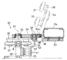
図7および図8に明示するように、前記前後一対の被案内部30,30のいずれもは、メインフレーム11aの下面側に固定されているガイドブラケット33から車体11の横外側に延出するガイドアーム34と、このガイドアーム34の延出端側にこの箇所を回転自在に貫通する回転支軸35によって車体上下方向の軸芯P1まわりで回転自在に取付けたローラ支持体36と、このローラ支持体36から下向きに延出する4本のローラ支軸37それぞれに1個ずつ回転自在に取付けた計4個の前記ガイドローラ31・32・とによって構成してある。ガイドアーム34の基端側に備えた長孔34aと、この長孔34aを貫通するように構成してガイドブラケット33に付設した車体前後方向のアーム連結ピン38とによってガイドアーム34とガイドブラケット33とを連結し、ガイドアーム34をアーム連結ピン38を支点にしてガイドブラケット33に対して上下に揺動操作することにより、被案内部30を図8に実線で示す如く4個のガイドローラ31,32が車体11から横外側に突出するとともに前記ガイドレール8に上方から装着して接触作用する下降使用状態と、図8に二点鎖線で示す如く4個のガイドローラ31,32がガイドレール8から上方に抜け出るとともに下降使用状態のときよりも車体側に寄る上昇格納状態とに切り換えできるようにしてある。被案内部30をガイドレール8に作用させる際には、ガイドアーム34の基端側にその上面側から装着してガイドアーム34をガイドブラケット33に締付け固定するように構成した複数本のロックボルト39を作用させることにより、前記下降使用状態に固定するようにしてある。被案内部30を下降使用状態にすると、前記軸芯P1がガイドレール8の直上方に位置し、かつ、前記4個のガイドローラ31・32・のうちの前記軸芯P1よりも車体外側に位置する2個のガイドローラ31,31がガイドレール8の左側の側面に車体前後方向に並んで接触し、前記軸芯P1よりも車体内側に位置する2個のガイドローラ32,32がガイドレール8の右側の側面に車体前後方向に並んで接触するように構成してある。これにより、前後一対の被案内部30,30を前記下降使用状態にして固定すると、両被案内部30,30は、駆動輪12による推進作用と、4個のガイドローラ31,32の案内作用とのためにガイドレール8に沿って移動し、車体11をガイドレール8に沿って走行するように操向制御する。
【0020】
前記一対の被案内部30,30を下降使用状態にすると、駆動輪12と両被案内部30,30とが図2および図10に示す位置関係になるように駆動輪12と両被案内部30,30とを配置してある。すなわち、一対の被案内部30,30どうしの車体前後方向での中心を通る車体横方向の直線KLを仮想すると、この仮想直線KLの上に駆動輪12の車軸芯Yが位置するように、かつ、ガイドレール8に駆動輪12が旋回内側に位置することになる湾曲部が存在し、車体11がこの湾曲部に沿って旋回中心Qのまわりで旋回するとすると、駆動輪12が旋回中心Qとガイドレール8との間に位置するようにしてある。これにより、ガイドレール8が湾曲していても、駆動輪12による車体11の推進が可能になる。また、前後一対の被案内部30,30のいずれにも、駆動輪12による推進力Fと同じ方向で同じ強さの操作力Fが作用し、この操作力Fの接線方向の第1分力F1が被案内部30をガイドレール8に沿わせて移動させるように作用し、前記操作力Fの法線方向の第2分力F2のためにガイドレール8からの反力Rが発生する。そして、この反力Rのため、車体11に駆動輪12の接地点まわりで回転させるモーメントが作用する。しかし、一方の被案内部30から駆動輪12までの距離L1と、他方の被案内部30から駆動輪12までの距離L2とが等しくなり、一方の被案内部30に発生する反力Rによる回転モーメントと、他方の被案内部30に発生する反力Rによる回転モーメントとが釣り合う。
【0021】
図2および図9に示すように、前記前後の荷受け台装置40,40のいずれもは、メインフレーム11aと11bとにわたって取付けたコンベアケース41と、このコンベアケース41に前記電動モータM2によって正回転方向と逆回転方向とに回動駆動できるように取付けた無端チェーンでなるチェーンコンベア42と、前記コンベアケース41が支持する搬送ガイド43とによって構成してある。すなわち、前後いずれもの荷受け台装置40は、パレットPの一端側を正回転方向に回動する無端チェーン42によって搬送ガイド43に沿わせてコンベアケース41の上方に搬入することにより、搬送用の物品Aを前記移載リフタ5cや物品搬入部6から車体11に積み込む。そして、コンベアケース41の上方に位置するパレットPの一端側を逆回転方向に回動する無端チェーン42によって搬送ガイド43に沿わせて車体11の横外側に搬出することにより、搬送用の物品Aを車体11から前記移載リフタ4cや物品搬出部7に降ろす。
【0022】
図8に示すように、前記前後一対のガイドブラケット33,33のいずれか一方のガイドブラケット33から延出する集電アーム50に車体上下方向に並ぶ複数個の集電子51を支持させるとともに、これら集電子51は、ガイドレール8の支柱52が支持する給電レール53に接触し、駆動用電力を給電レール53から取り入れるとともに前記電源部16を介して前記電動モータM1,M2に供給するように構成してある。
【0023】
つまり、搬送車Tは、前後一対の被案内部30,30によってガイドレール8に沿うように操向制御されながら、かつ、集電子51によって駆動用電力を給電レール53から取り入れて電動モータM1に供給しながら、1個の駆動輪12と2個の従動輪13,13とに荷重を支持させながらこれら3個の車輪12,13,13によって床面上を自走していく。ガイドレール8が湾曲していても、ローラ支持体36が軸芯P1まわりで車体11に対して回動し、全てのガイドローラ31,32がガイドレール8に確実に接触して被案内部30がガイドレール8に精度よく沿うことにより、かつ、前側の被案内部30に作用する前記反力Rによって車体11に作用する回転モーメントと、後側の被案内部30に作用する前記反力Rによって車体11に作用する回転モーメントとが釣り合うことにより、各被案内部30,30とガイドレール8との間にこじれが発生しにくいとともに駆動輪12の推進力のロスが発生しにくくてガイドレール8の湾曲部に沿ってスムーズに走行していく。また、車体11が走行振動や床面凹凸などに起因して前後に傾斜しても、補助輪14が上昇限界に至った際にはそれ以上傾斜しないように補助輪14によって支持されて安定よく走行していく。そして、物品搬入の際には、物品搬入部6の横側で停止して前後一対のチェーンコンベア42,42によってパレットPを前側の荷受け装置40と後側の荷受け装置と40にわたって搬入することによって物品Aを積み込み、いずれかの搬入装置4の移載リフト4cの横側で停止して前後一対のチェーンコンベア42,42によってパレットPを両荷受け装置40,40から搬出することによって物品Aを移載リフト4cに降ろす。また、物品搬出の際には、いずれかの搬出装置5の移載リフタ5cの横側で停止して前後一対のチェーンコンベア42,42によってパレットPを前側の荷受け装置40と後側の荷受け装置と40にわたって搬入することによって物品Aを積み込み、物品搬出部7の横側で停止して前後一対のチェーンコンベア42,42によってパレットPを両荷受け装置40,40から搬出することによって物品Aを物品搬出部7に降ろす。
【0027】
〔別実施形態〕
前記補助輪14は省略して実施する搬送車の場合にも本発明は適用できる。
【0028】
前記ガイドレール8に替え、搬送車Tの搬送経路に沿わせて床面に形成するガイド溝を採用して実施する搬送車Tの場合にも本発明は適用できる。したがって、これらガイドレール8、ガイド溝を総称して案内体と呼称する。
【図面の簡単な説明】
【図1】自動倉庫の概略平面図
【図2】搬送車全体の平面図
【図3】搬送車全体の後面図
【図4】駆動輪取付け部の後面図
【図5】従動輪取付け部の後面図
【図6】補助輪取付け部の側面図
【図7】被案内部の平面図
【図8】被案内部の取付け部の断面図
【図9】荷受け装置の断面図
【図10】本発明の駆動輪による推進作用の説明図
【図11】従来の駆動輪による推進作用の説明図
【符号の説明】
8 案内体
12 駆動輪
13 従動輪
30 被案内部
31 ガイドローラ
32 ガイドローラ
36 ローラ支持体
KL 仮想直線
Q 旋回中心[0001]
BACKGROUND OF THE INVENTION
The present invention includes a vehicle body including a pair of front and rear guided parts that move along a guide body, such as a transport vehicle that carries out and carries articles in an automatic warehouse, and a driving wheel and a driven wheel on a floor surface. The present invention relates to a transport vehicle that self-propels along the guide body.
[0002]
[Prior art]
In the above-described transport vehicle, conventionally, as disclosed in, for example, Japanese Patent Application Laid-Open No. 59-59564, a frame that supports a front wheel as a driven wheel and a frame that supports a rear wheel as a drive wheel are connected to a vehicle body via a turning device. When the guide rail is curved, the steering device as a guided part that moves along the guide rail as a guided body is provided on the support frame of the front wheels and the rear wheels. For this reason, the support frame pivoted with respect to the vehicle body, and the mounting direction of the driving wheel and the driven wheel to the vehicle body became the mounting direction along the guide rail, and the vehicle body traveled along the guide rail. . That is, the steering wheel and the driven wheel are steered by the steering device, and the vehicle body is steered so as to travel along the guide body.
Further, as disclosed in, for example, Japanese Patent Publication No. 59-45541, the vehicle body includes a pair of front and rear guide rollers that move along a guide groove as a guide body, and the driving wheel and the driven wheel are operated. If the guide groove is bent and the guide groove is curved, the guide roller guides the vehicle from the front side to the rear side, so that the vehicle body travels along the guide groove. It was. In other words, the guided portion is guided by the guide body and steers the vehicle body so as to travel along the guide body.
[0003]
[Problems to be solved by the invention]
In the case of the above-described conventional steering technology, since the steering wheel is configured so that the driving wheel and the driven wheel are steered, for example, the wheel support member is pivotally supported on the vehicle body, There is a need for a structure that enables steering of the wheels, and there is a problem that the structure becomes complicated and the vehicle body becomes heavy. In addition, as a result of the complicated structure, there is also a problem that the maintainability is deteriorated such that inspection and maintenance are difficult. Furthermore, since the structure that enables the steering of the wheel is generally installed in the lower part of the vehicle body, there has been a problem that the vehicle body height becomes high.
In the latter conventional steering technology described above, neither the steering control of the driving wheels nor the steering control of the driven wheels is performed, so that a steering mechanism for steering control of the wheels is unnecessary. The vehicle body can be steered along the guide body while solving problems such as structural surfaces, weight surfaces, and vehicle heights that occur in the case of steering technology. However, in the case of this conventional steering technology, as will be described later, the guide wheel and the guided part may be twisted due to the arrangement relationship between the driving wheel and the guided part, or the driving loss of the driving wheel is large. It was easy to cause trouble.
An object of the present invention is to provide a transport vehicle that is not only advantageously obtained in terms of structure, weight, vehicle height, and the like, but is less likely to cause the above-described twisting and driving loss even when the guide body is curved. is there.
[0004]
[Means for Solving the Problems]
To achieve the object, according to the first aspect of the present invention, in the carrier vehicle described at the beginning, the driving wheel and the driven wheel are configured as non-steering wheels, and the axle core of the driving wheel is the pair of covered wheels. Even if the guide body is curved, even if the guide body is curved, it is curved because the driving wheels and the guided part are arranged so that they are positioned on a virtual straight line in the lateral direction of the vehicle body that passes through the center of the vehicle body in the longitudinal direction of the vehicle body. If the guided wheel is located at the center and the driving wheel is located inside the turning, the driving wheel is propelled by the driving wheel as long as the driving wheel is located between the turning center of the vehicle and the guide body. Is possible. Since the pair of guided portions are guided by the guide body in a restrained state and steer the vehicle body along the guide body, the vehicle body guides the vehicle without using a steering mechanism for steering the drive wheels and the driven wheels. It is possible to run along the body, it can be obtained with a simple structure and light weight, it can be easily inspected and maintained, and the body height is lowered as much as possible to run advantageously on a stable surface etc. You can
[0005]
As shown in FIGS. 10 and 11, a pair of front and rear guided
[0006]
According to the first aspect of the present invention, since the pair of guided portions protrudes laterally outward from the vehicle body, even if the guide body is disposed near the wall, the guided portion is caused to act on the vehicle body. The vehicle can travel along the guide body, and when the vehicle body travel route on the floor surface is used for other than vehicle body travel, the transport vehicle can be used while the guide body does not easily become an obstacle and can be used advantageously.
[0007]
According to the first aspect of the present invention, since the driving wheel is deviated to the side where the guided portion is located with respect to the center of the vehicle body in the left-right direction, the driving wheel is moved to the guided portion. Even if the vehicle body rotates around the guided part due to the propulsive force of the driving wheel and a twist occurs between the guided part and the guiding body, the contact between the driving wheel and the guided part Twist is relatively small from the surface of the distance, and the guided portion also moves smoothly along the guide body from this surface.
[0008]
In addition, according to the invention described in
[0009]
According to the second aspect of the present invention, since the driven wheel has a caster wheel function, the driven wheel always travels for the caster wheel function even if the traveling direction of the vehicle body changes along the guide body. The mounting orientation that faces the direction naturally changes and can roll smoothly, and the vehicle body runs smoothly even if the driven wheel is a steered wheel.
[0010]
According to the third aspect of the present invention, when the vehicle body turns along the curved portion of the guide body and the drive wheel is positioned inside the turn, the drive wheel has a turning center of the vehicle body, the guide body, Since the drive wheels are arranged so as to be positioned between the guide wheels, even if the guide body is curved and the drive wheels pass through the inside of the curved portion, the drive wheels reliably exert the propulsion action and the vehicle body Will run smoothly and reliably.
[0011]
According to the fourth aspect of the present invention, each of the pair of guided portions is in contact with the left side of the guide body and is in contact with the right side of the guide body with two guide rollers arranged in the longitudinal direction of the vehicle body. Since two guide rollers are arranged in the longitudinal direction of the vehicle body, even if the guide body is curved, at least one guide roller acts on either of the left and right sides. It is difficult for the situation of being completely separated, and the vehicle body is reliably steered so as to accurately follow the guide body regardless of whether the guide body is curved.
[0012]
According to the fifth aspect of the present invention, each of the pair of guided portions is supported by the vehicle body so as to be rotatable around an axis in the vertical direction of the vehicle body located above the guide body, and the four pieces. Since the roller support for supporting the guide roller is provided, even if the guide is curved, the roller support rotates so that two guide rollers act as much as possible on both the left and right sides, Regardless of whether or not the guide body is curved, the vehicle body is reliably steered so as to follow the guide body more accurately.
[0013]
DETAILED DESCRIPTION OF THE INVENTION
As shown in FIG. 1, the storage unit 1a for storing and storing various articles A in a state of being placed on the pallet P includes a plurality of
[0014]
That is, when the article A is stored, it is supplied to the article carry-in section 6 by the
And when taking out article | item A, the instruction | command is input into a control apparatus. Then, the
[0015]
The transport vehicle T is configured as shown in FIGS.
That is, the
[0016]
As shown in FIG. 4, the
[0017]
As clearly shown in FIG. 5, each of the pair of front and rear driven
[0018]
As shown in FIG. 6, each of the pair of front and rear
[0019]
As clearly shown in FIGS. 7 and 8, each of the pair of front and rear guided
[0020]
When the pair of guided
[0021]
As shown in FIGS. 2 and 9, each of the front and rear load receiving
[0022]
As shown in FIG. 8, a
[0023]
That is, the transport vehicle T is steered along the
[0027]
[Another embodiment]
The present invention can also be applied to a transport vehicle that omits the
[0028]
The present invention can be applied to the case of the transport vehicle T that is implemented by adopting a guide groove formed on the floor surface along the transport path of the transport vehicle T instead of the
[Brief description of the drawings]
[Fig. 1] Schematic plan view of an automatic warehouse [Fig. 2] Plan view of the entire transport vehicle [Fig. 3] Rear view of the entire transport vehicle [Fig. 4] Rear view of the drive wheel mounting portion [Fig. Rear view [Fig. 6] Side view of auxiliary wheel mounting portion [Fig. 7] Plan view of guided portion [Fig. 8] Cross-sectional view of guided portion mounting portion [Fig. 9] Cross-sectional view of load receiving device [Fig. Explanatory drawing of the propulsion action by the drive wheel of the invention [FIG. 11] Explanatory drawing of the propulsion action by the conventional drive wheel [Explanation of symbols]
8
Claims (5)
前記駆動輪および前記従動輪を非操舵輪に構成するとともに、前記駆動輪の車軸芯が前記一対の被案内部どうしの車体前後方向での中心を通る車体横方向の仮想直線上に位置するように前記駆動輪と前記被案内部とを配置し、
前記一対の被案内部が、車体から横外側に突出し、且つ、前記案内体に拘束状態で案内されて前記車体を前記案内体に沿うように操向させるように構成され、
前記駆動輪を1個備え、前記従動輪を2個備え、
前後一対の前記従動輪が車体の左右方向での中心に対して前記被案内部から離れる側に偏位し、
前記駆動輪が車体の左右方向での中心に対して前記被案内部が位置する側に偏位している搬送車。A pair of front and rear guided parts that move along the guide body is provided on the vehicle body, and the vehicle is self-propelled along the guide body by driving wheels and driven wheels on the floor surface,
The driving wheel and the driven wheel are configured as non-steering wheels, and the axle core of the driving wheel is positioned on a virtual straight line in the lateral direction of the vehicle body that passes through the center of the pair of guided portions in the longitudinal direction of the vehicle body. The drive wheel and the guided portion are arranged in
The pair of guided portions project laterally outward from the vehicle body, and are guided by the guide body in a restrained state so as to steer the vehicle body along the guide body;
One drive wheel, two driven wheels,
The pair of front and rear driven wheels are displaced to the side away from the guided portion with respect to the center of the vehicle body in the left-right direction;
A transport vehicle in which the driving wheel is deviated to a side where the guided portion is located with respect to a center in a left-right direction of a vehicle body.
Priority Applications (2)
| Application Number | Priority Date | Filing Date | Title |
|---|---|---|---|
| JP28198196A JP3663263B2 (en) | 1996-10-24 | 1996-10-24 | Transport vehicle |
| US08/862,936 US6036427A (en) | 1996-05-29 | 1997-05-29 | Guided vehicle system for transporting loads |
Applications Claiming Priority (1)
| Application Number | Priority Date | Filing Date | Title |
|---|---|---|---|
| JP28198196A JP3663263B2 (en) | 1996-10-24 | 1996-10-24 | Transport vehicle |
Publications (2)
| Publication Number | Publication Date |
|---|---|
| JPH10119765A JPH10119765A (en) | 1998-05-12 |
| JP3663263B2 true JP3663263B2 (en) | 2005-06-22 |
Family
ID=17646591
Family Applications (1)
| Application Number | Title | Priority Date | Filing Date |
|---|---|---|---|
| JP28198196A Expired - Fee Related JP3663263B2 (en) | 1996-05-29 | 1996-10-24 | Transport vehicle |
Country Status (1)
| Country | Link |
|---|---|
| JP (1) | JP3663263B2 (en) |
Families Citing this family (2)
| Publication number | Priority date | Publication date | Assignee | Title |
|---|---|---|---|---|
| WO2020045221A1 (en) * | 2018-08-27 | 2020-03-05 | ケイズ技研株式会社 | Universal caster |
| DE102021102633A1 (en) * | 2021-02-04 | 2022-08-04 | Jungheinrich Aktiengesellschaft | Method for determining an orientation of an industrial truck |
-
1996
- 1996-10-24 JP JP28198196A patent/JP3663263B2/en not_active Expired - Fee Related
Also Published As
| Publication number | Publication date |
|---|---|
| JPH10119765A (en) | 1998-05-12 |
Similar Documents
| Publication | Publication Date | Title |
|---|---|---|
| CN105041024A (en) | Tire clamping apparatus and vehicle transportation device with the tire clamping apparatus | |
| KR100342266B1 (en) | Cargo transport equipment and its guidance equipment | |
| KR950000594B1 (en) | Storage and conveyance of heavy articles | |
| JP3867866B2 (en) | Automated guided vehicle | |
| JP3663263B2 (en) | Transport vehicle | |
| TW200403178A (en) | Carrying apparatus | |
| KR102587566B1 (en) | Transport vehicle and transport system comprising the same | |
| JP3503728B2 (en) | Guided structure of carrier | |
| JP3431120B2 (en) | Goods transport equipment | |
| JP3460917B2 (en) | Carrier | |
| JPH05270396A (en) | Railless automatic guided vehicle | |
| JP3402432B2 (en) | Goods carrier | |
| JP2007119145A (en) | Conveying truck | |
| JPH10181585A (en) | Carrying vehicle | |
| JPH11124028A (en) | Carrier | |
| JP3431121B2 (en) | Goods transport equipment | |
| JP2000355275A (en) | Track carriage system | |
| JP2003206003A (en) | Floor travelling type truck system | |
| JP3388148B2 (en) | Goods transport equipment | |
| KR100654815B1 (en) | Electronic equipment transfer equipment | |
| JPH0286514A (en) | Conveyor device for classification | |
| JP2019098904A (en) | Bogie wheel structure | |
| JPS6111122Y2 (en) | ||
| JPH11139307A (en) | Carrying facilities | |
| JP2025026078A (en) | Guiding device and transport device |
Legal Events
| Date | Code | Title | Description |
|---|---|---|---|
| A521 | Written amendment |
Free format text: JAPANESE INTERMEDIATE CODE: A523 Effective date: 20050218 |
|
| A61 | First payment of annual fees (during grant procedure) |
Free format text: JAPANESE INTERMEDIATE CODE: A61 Effective date: 20050328 |
|
| R150 | Certificate of patent (=grant) or registration of utility model |
Free format text: JAPANESE INTERMEDIATE CODE: R150 |
|
| FPAY | Renewal fee payment (prs date is renewal date of database) |
Free format text: PAYMENT UNTIL: 20080401 Year of fee payment: 3 |
|
| FPAY | Renewal fee payment (prs date is renewal date of database) |
Free format text: PAYMENT UNTIL: 20090401 Year of fee payment: 4 |
|
| FPAY | Renewal fee payment (prs date is renewal date of database) |
Free format text: PAYMENT UNTIL: 20100401 Year of fee payment: 5 |
|
| FPAY | Renewal fee payment (prs date is renewal date of database) |
Free format text: PAYMENT UNTIL: 20110401 Year of fee payment: 6 |
|
| FPAY | Renewal fee payment (prs date is renewal date of database) |
Free format text: PAYMENT UNTIL: 20110401 Year of fee payment: 6 |
|
| FPAY | Renewal fee payment (prs date is renewal date of database) |
Free format text: PAYMENT UNTIL: 20110401 Year of fee payment: 6 |
|
| FPAY | Renewal fee payment (prs date is renewal date of database) |
Free format text: PAYMENT UNTIL: 20120401 Year of fee payment: 7 |
|
| FPAY | Renewal fee payment (prs date is renewal date of database) |
Free format text: PAYMENT UNTIL: 20130401 Year of fee payment: 8 |
|
| FPAY | Renewal fee payment (prs date is renewal date of database) |
Free format text: PAYMENT UNTIL: 20130401 Year of fee payment: 8 |
|
| FPAY | Renewal fee payment (prs date is renewal date of database) |
Free format text: PAYMENT UNTIL: 20140401 Year of fee payment: 9 |
|
| R250 | Receipt of annual fees |
Free format text: JAPANESE INTERMEDIATE CODE: R250 |
|
| LAPS | Cancellation because of no payment of annual fees |