CN115427324A - Traveling carriage and automated warehouse - Google Patents
Traveling carriage and automated warehouse Download PDFInfo
- Publication number
- CN115427324A CN115427324A CN202180027193.8A CN202180027193A CN115427324A CN 115427324 A CN115427324 A CN 115427324A CN 202180027193 A CN202180027193 A CN 202180027193A CN 115427324 A CN115427324 A CN 115427324A
- Authority
- CN
- China
- Prior art keywords
- guide member
- traveling
- traveling carriage
- travel
- guide
- Prior art date
- Legal status (The legal status is an assumption and is not a legal conclusion. Google has not performed a legal analysis and makes no representation as to the accuracy of the status listed.)
- Pending
Links
Images


Classifications
-
- B—PERFORMING OPERATIONS; TRANSPORTING
- B65—CONVEYING; PACKING; STORING; HANDLING THIN OR FILAMENTARY MATERIAL
- B65G—TRANSPORT OR STORAGE DEVICES, e.g. CONVEYORS FOR LOADING OR TIPPING, SHOP CONVEYOR SYSTEMS OR PNEUMATIC TUBE CONVEYORS
- B65G1/00—Storing articles, individually or in orderly arrangement, in warehouses or magazines
- B65G1/02—Storage devices
- B65G1/04—Storage devices mechanical
- B65G1/06—Storage devices mechanical with means for presenting articles for removal at predetermined position or level
- B65G1/065—Storage devices mechanical with means for presenting articles for removal at predetermined position or level with self propelled cars
-
- B—PERFORMING OPERATIONS; TRANSPORTING
- B65—CONVEYING; PACKING; STORING; HANDLING THIN OR FILAMENTARY MATERIAL
- B65G—TRANSPORT OR STORAGE DEVICES, e.g. CONVEYORS FOR LOADING OR TIPPING, SHOP CONVEYOR SYSTEMS OR PNEUMATIC TUBE CONVEYORS
- B65G1/00—Storing articles, individually or in orderly arrangement, in warehouses or magazines
- B65G1/02—Storage devices
- B65G1/04—Storage devices mechanical
- B65G1/0407—Storage devices mechanical using stacker cranes
- B65G1/0435—Storage devices mechanical using stacker cranes with pulling or pushing means on either stacking crane or stacking area
-
- B—PERFORMING OPERATIONS; TRANSPORTING
- B65—CONVEYING; PACKING; STORING; HANDLING THIN OR FILAMENTARY MATERIAL
- B65G—TRANSPORT OR STORAGE DEVICES, e.g. CONVEYORS FOR LOADING OR TIPPING, SHOP CONVEYOR SYSTEMS OR PNEUMATIC TUBE CONVEYORS
- B65G2203/00—Indexing code relating to control or detection of the articles or the load carriers during conveying
- B65G2203/02—Control or detection
- B65G2203/0266—Control or detection relating to the load carrier(s)
- B65G2203/0283—Position of the load carrier
-
- B—PERFORMING OPERATIONS; TRANSPORTING
- B65—CONVEYING; PACKING; STORING; HANDLING THIN OR FILAMENTARY MATERIAL
- B65G—TRANSPORT OR STORAGE DEVICES, e.g. CONVEYORS FOR LOADING OR TIPPING, SHOP CONVEYOR SYSTEMS OR PNEUMATIC TUBE CONVEYORS
- B65G2203/00—Indexing code relating to control or detection of the articles or the load carriers during conveying
- B65G2203/04—Detection means
- B65G2203/042—Sensors
- B65G2203/044—Optical
Abstract
The invention relates to a traveling carriage and an automated warehouse, which can arrange a plurality of traveling auxiliary rollers along a traveling direction with high precision. The traveling carriage (7) is provided with a side arm (253), a first guide member (21 a), and at least 2 or more traveling auxiliary rollers (27). The side arm (253) extends and contracts in the Y direction. The first guide member (21 a) extends in the X direction and has a third inner surface (IP 3) that guides the side arm (253) in the X direction. At least 2 or more travel assist rollers (27) are provided on the first guide member (21 a) and suppress the movement of the travel carriage (7) in the Y direction.
Description
Technical Field
The present invention relates to a traveling vehicle traveling in a predetermined direction, and more particularly to a traveling vehicle traveling guided by a traveling rail extending in the predetermined direction, and an automated warehouse including the traveling vehicle and a rack for storing goods.
Background
Conventionally, there has been known a traveling carriage which is provided for each of shelves provided in multiple stages in a height direction and travels in a longitudinal direction of the shelf on which the traveling carriage is provided. The traveling carriage travels in the longitudinal direction of the shelf by being guided by a traveling rail extending in the longitudinal direction of the shelf on which the traveling carriage is provided. Further, a pair of travel assist rollers for assisting travel of the traveling carriage is provided in the traveling carriage in a row in the longitudinal direction of the travel rail (for example, patent document 1).
Documents of the prior art
Patent document
Patent document 1: japanese laid-open patent publication No. 11-278607
Disclosure of Invention
Problems to be solved by the invention
In a conventional traveling carriage, one of a pair of traveling assist rollers is attached to a front frame provided on a front side in a traveling direction, and the other traveling assist roller is attached to a rear frame provided on a rear side in the traveling direction. The front frame and the rear frame are coupled by a pair of members extending in the traveling direction of the traveling carriage.
In the traveling carriage having such a configuration, the front frame and the rear frame may not be accurately and parallelly arranged due to a machining error of a member for coupling the front frame and the rear frame, a mounting error in coupling the front frame and the rear frame, a machining error of another component of the traveling carriage, a mounting error of the other component, and/or the like. As a result, the travel assist roller provided on the front frame and the travel assist roller provided on the rear frame may not be accurately aligned in parallel with the traveling direction.
When the travel assist roller is not arranged accurately and parallel to the traveling direction, the traveling carriage is not arranged appropriately with respect to the traveling rail, and therefore the traveling carriage cannot travel appropriately along the traveling rail.
The purpose of the present invention is to arrange a plurality of travel assist rollers along a travel direction with high accuracy in a travel carriage that travels along the travel direction and is provided with the plurality of travel assist rollers arranged in line along the travel direction.
Means for solving the problems
Hereinafter, a plurality of embodiments will be described as means for solving the problem. These means can be combined arbitrarily as needed.
A traveling vehicle according to an aspect of the present invention is a traveling vehicle that travels on a traveling path extending in a first direction. The traveling carriage is provided with a side arm, a guide member, and at least 2 or more traveling assist rollers.
The side arm is telescopic in a second direction. The second direction is a direction orthogonal to the first direction among the horizontal directions.
The guide member extends in the first direction and has a guide surface for guiding the side arm in the first direction.
At least 2 or more travel assist rollers are provided on the guide member, and suppress movement of the traveling carriage in the second direction.
In the traveling carriage, the plurality of traveling assist rollers are provided on a guide member extending in a first direction identical to a traveling direction of the traveling carriage. Since the guide member extends along the first direction, that is, the traveling direction of the traveling carriage, the plurality of travel assist rollers can be accurately arranged along the traveling direction of the traveling carriage by providing the plurality of travel assist rollers on the guide member. As a result, the straight-ahead performance of the traveling carriage can be improved.
The guide member may be provided along the entire length of the traveling carriage in the first direction. The guide member may have a first portion for guiding the side arm and a second portion located outside the first portion in the first direction. In this case, the travel assist roller is provided at the second portion of the guide member.
By providing the travel assist roller at the second portion of the guide member, the travel assist roller can be provided at an end portion of the entire length of the traveling carriage in the first direction, and therefore the travel assist roller can be disposed parallel to the traveling direction over the entire length of the traveling carriage in the first direction. As a result, the straight-ahead performance of the traveling carriage can be improved.
In the traveling carriage, a pair of the guide members may be provided so as to be separated in the second direction. In this case, the traveling carriage may further include a first coupling member and a second coupling member. The first coupling member and the second coupling member couple the pair of guide members at end portions of the pair of guide members in the first direction and at inner sides of the pair of guide members in the second direction.
Thus, the traveling carriage can be assembled with the guide member as a reference while the guide member is used as a member for guiding the side arm in the first direction. That is, the guide member can have a function of guiding the side arm and a function of a frame of the traveling carriage. As a result, the number of components of the traveling carriage can be reduced.
The traveling carriage may further include an auxiliary member provided to the guide member. The auxiliary member may be at least one of a current collecting member for supplying power to the traveling carriage, a detection member for detecting a traveling position of the traveling carriage, a stopper for stopping the traveling carriage, or an optoelectronic device for irradiating light toward the outside with respect to the first direction.
In this way, by providing the auxiliary member for assisting the traveling of the traveling carriage with reference to the guide member, the auxiliary member can be easily assembled to the traveling carriage.
The photoelectric device may be attached to an attachment surface of the attachment member that abuts the guide member so as to irradiate the light outward with respect to the first direction. Thus, when the guide member is parallel to the first direction, the irradiation direction of the light from the electro-optical device can be made nearly parallel to the first direction, and the deviation between the irradiation direction of the light from the electro-optical device and the first direction can be reduced.
The traveling carriage may further include a block member. The block member is fixed to the guide member in a state of being inserted into a space formed in the guide member. At least one of the travel assist roller and the assist member is mounted on the block member.
This makes it possible to collectively mount the travel assist roller and/or the assist member on the common block member, and to easily mount the travel assist roller and/or the assist member on the guide member.
The travel path may also have a travel plane portion and a movement suppression portion. The traveling plane portion is a portion that becomes a traveling plane of the traveling carriage. The movement suppressing portion is a portion extending from the traveling plane portion to the third direction, and suppresses movement of the traveling carriage in the second direction by the traveling auxiliary roller coming into contact therewith. The third direction is a direction orthogonal to the first direction and the second direction.
This makes it possible to provide the traveling path with a function as a traveling path for the traveling carriage and a function of suppressing the traveling carriage from moving in the second direction.
The travel assist roller may have a pair of rollers. The pair of rollers are disposed at a predetermined interval in the second direction. In addition, the movement restraining portion is sandwiched between the pair of rollers. This can further suppress the movement of the traveling carriage in the second direction.
The guide member may have any one of a C-shape, an L-shape, or a quadrangular shape in cross section. This can improve the rigidity of the guide member.
The block member may be configured to be able to be pulled out from an end of the guide member in the first direction from a state of being inserted into the guide member. The block member may be inserted into the guide member by being inserted from an end of the guide member in the first direction.
Thus, the travel assist roller and/or the assist member can be easily attached to and detached from the guide member in a state where the traveling carriage is attached to the travel path.
An automated warehouse according to another aspect of the present invention includes the traveling carriage, and a rack for storing the goods transferred from and/or to the traveling carriage.
ADVANTAGEOUS EFFECTS OF INVENTION
By providing a plurality of travel assist rollers on the guide member parallel to the traveling direction of the traveling carriage, the plurality of travel assist rollers can be accurately arranged along the traveling direction of the traveling carriage. As a result, the straight advancement of the traveling carriage in the first direction can be improved.
Drawings
Fig. 1 is a top view of an automated warehouse.
FIG. 2 is a perspective view of the traveling carriage and the rack
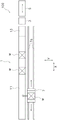
Fig. 3 is an enlarged view of the vicinity of the traveling portion of the traveling carriage as viewed from the X direction.
FIG. 4 is a detailed perspective view of the traveling carriage
Fig. 5 is a perspective view of the guide member of the traveling carriage and the accompanying components and the like, as viewed from the upper right side.
Fig. 6 is a perspective view of the guide member of the traveling carriage and the components attached thereto, etc., as viewed from the upper left side.
Fig. 7 is a perspective view of the guide member of the traveling carriage and the components attached thereto, etc., as viewed from the lower left side.
Fig. 8 is a diagram showing the definition of the surface of the guide member.
Fig. 9 is a view showing a modification of the installation state of the travel assist roller to the guide member of the traveling carriage.
Detailed Description
1. First embodiment
(1) Automated warehouse
The automated warehouse 100 provided with the traveling carriage 7 according to the first embodiment will be described below with reference to fig. 1 to 3. Fig. 1 is a plan view of the automated warehouse 100, and fig. 2 is a perspective view showing the traveling carriage 7 and the rack 1. Fig. 3 is an enlarged view of the traveling portion 31 of the traveling carriage 7 viewed from the X direction. In the following description, the left-right direction in fig. 1 is referred to as the X direction (an example of a first direction), the up-down direction in fig. 1, that is, the direction orthogonal to the X direction in the horizontal direction is referred to as the Y direction (an example of a second direction), and the up-down direction in fig. 2 perpendicular to the X direction and the Y direction is referred to as the Z direction (an example of a third direction).
The automated warehouse 100 includes a rack 1, an elevating conveyor 3, an entry/exit station 5, a plurality of traveling carriages 7, and a rail 7a (an example of a traveling path).
The shelf 1 stores goods W. Specifically, the shelf 1 has a plurality of shelves 11. The shelf plates 11 extend in the X direction and are arranged at predetermined intervals in the Z direction. The goods W are placed on any of the shelf boards 11 and stored.
Further, a relay conveyor 13 is provided on each shelf 11. The relay conveyor 13 is provided near the lifting and conveying device 3, and transfers the goods W stored in the warehouse from the lifting and conveying device 3. The goods W taken out of the warehouse are transferred from the traveling carriage 7.
In the present embodiment, as shown in fig. 1, the pallet 1 is disposed only on one side in the Y direction with respect to the traveling carriage 7 (rail 7 a). However, the present invention is not limited to this, and the racks 1 may be disposed on both sides of the traveling carriage 7 (rail 7 a) in the Y direction.
The elevation transport device 3 is disposed between the shelf 1 and the storage/retrieval station 5, and has an elevation table. The lifting platform can be lifted and lowered in the Z direction in the lifting and conveying device 3 in a state of supporting a plurality of loads. The elevating platform includes, for example, a conveyor for transferring the goods W between the in-out storage station 5 and the relay conveyor 13 of the rack 1.
The storage/retrieval station 5 conveys the goods W stored (retrieved) on the shelf 11 of the rack 1 from the outside to the vicinity of the elevation transport device 3. The loading/unloading station 5 conveys the load W conveyed by the elevating conveyor 3 to the outside for unloading. The warehouse entry and exit station 5 is a conveyor such as a belt conveyor.
The rail 7a is a member provided on each shelf 11 of the shelf 1 and extending in the X direction. The traveling carriage 7 provided on each shelf 11 travels in the X direction while being guided by the rail 7a provided on the corresponding shelf 11. As shown in fig. 3, the rail 7a has a running surface portion 71 and a movement restraining portion 73.
The traveling plane portion 71 is a portion extending in the X direction in parallel with the X-Y plane, and serves as a traveling plane on which the traveling carriage 7 travels. The movement restraining portion 73 is a portion that protrudes in the Z direction from the end of the traveling plane portion 71 in the Y direction and extends in the X direction. The movement suppressing portion 73 is abutted by the roller 27a of the travel assist roller 27 to suppress the travel carriage 7 from moving in the Y direction.
The track 7a has the travel surface portion 71 and the movement suppressing portion 73, and thus the track 7a can have a function as a travel path of the traveling carriage 7 and a function of suppressing the movement of the traveling carriage 7 in the Y direction.
(2) Traveling carriage
(2-1) brief description of traveling carriage
Each of the traveling carriages 7 is a carriage capable of traveling in the X direction at a height corresponding to the height of each shelf 11. The traveling carriage 7 travels along the X direction while being guided by rails 7a laid at a height corresponding to each shelf 11 and extending along the X direction. The traveling carriage 7 further includes transfer devices 25 (fig. 4) for transferring the articles W between the intermediate conveyors 13 of the racks 1 and between the shelf 11.
With the above configuration, the traveling carriage 7 travels in the X direction along the shelf 11 on which it is disposed in a state of holding the load W, and can thereby convey the held load W in the X direction. Further, the goods W can be transferred between the traveling carriage 7 and the relay conveyor 13 and between the traveling carriage 7 and the shelf 11 by using the transfer device provided on the traveling carriage 7.
Specifically, at the time of warehousing the goods W, after the goods W transferred from the lifting and conveying device 3 to the relay conveyor 13 are transferred to the traveling carriage 7, the traveling carriage 7 moves in the X direction to the destination position of the shelf 11, and the goods W are transferred from the traveling carriage 7 to the shelf 11 at the destination position.
On the other hand, at the time of shipment, after the traveling carriage 7 is moved in the X direction to the target position of the shelf 11 and the cargo W is transferred from the shelf 11 to the traveling carriage 7 at the target position, the traveling carriage 7 is moved in the X direction to the arrangement position of the relay conveyor 13 and the cargo W is transferred from the traveling carriage 7 to the relay conveyor 13.
(2-2) detailed description of traveling carriage
The structure of the traveling carriage 7 according to the first embodiment will be described in detail below with reference to fig. 3 to 8. Fig. 4 is a detailed perspective view of the traveling carriage 7. Fig. 5 is a perspective view of the guide member of the traveling carriage 7 and the accompanying members and the like as viewed from the upper right side. Fig. 6 is a perspective view of the guide member of the traveling carriage 7 and the accompanying members and the like viewed from the upper left side. Fig. 7 is a perspective view of the guide member of the traveling carriage 7 and the accompanying members and the like, as viewed from the lower left side. Fig. 8 is a diagram showing the definition of the surface of the guide member.
The traveling carriage 7 includes a first guide member 21a, a second guide member 21b, a first body portion 23a, a second body portion 23b, a transfer device 25, and a traveling assist roller 27.
(2-2-1) guide Member
The first guide member 21a has a function of guiding the movement of the side arm 253 of the transfer device 25 in the traveling carriage 7 and a function of a frame that determines a reference position of each component.
The first guide member 21a is a member that is long in one direction. As shown in fig. 5 to 8, the first guide member 21a has a C-shape in a cross section perpendicular to the longitudinal direction.
Specifically, as shown in fig. 8, the first guide member 21a has a first inner surface IP1, a second inner surface IP2, and a third inner surface IP3 as inner surfaces of a C-shape. The first inner surface IP1 is a plane that is long in the longitudinal direction of the first guide member 21a and is arranged at the lower part of the C-shape. The second inner surface IP2 is a surface that is long in the longitudinal direction of the first guide member 21a and is parallel to the first inner surface IP1, and is disposed at the top of the C-shape. The third inner surface IP3 is a surface that is long in the longitudinal direction of the first guide member 21a and forms an angle of 90 degrees with the first inner surface IP1 and the second inner surface IP 2. The third inner side IP3 connects the first inner side IP1 with the second inner side IP 2.
On the other hand, the first guide member 21a has a first outer side surface OP1, a second outer side surface OP2, and a third outer side surface OP3 as outer surfaces of the C-shape. The first outer side surface OP1 is a plane that is long in the longitudinal direction of the first guide member 21a and is disposed at the lower portion of the C-shape. The second outer side surface OP2 is a surface that is long in the longitudinal direction of the first guide member 21a and is parallel to the first outer side surface OP1, and is disposed at the upper portion of the C-shape. The third outer side surface OP3 is a surface which is long in the longitudinal direction of the first guide member 21a and forms an angle of 90 degrees with the first outer side surface OP1 and the second outer side surface OP 2. The third inner side IP3 connects the first inner side IP1 with the second inner side IP 2.
By forming the cross section of the first guide member 21a into a C-shape as described above, the rigidity of the first guide member 21a can be improved.
When the traveling carriage 7 is attached to the rail 7a, the longitudinal direction of the first guide member 21a is parallel to the longitudinal direction (i.e., X direction) of the rail 7a. That is, the first guide member 21a is a member extending in the X direction parallel to the rail 7a in the traveling carriage 7.
The longitudinal direction of the first guide member 21a is parallel to the longitudinal direction of the rail 7a, and specifically, the following states are specified: as shown in fig. 3, when the traveling carriage 7 is attached to the rail 7a, the third inner surface IP3 and the third outer surface OP3 of the first guide member 21a are parallel to the movement suppressing portion 73 of the rail 7a parallel to the X-Z plane, and the first inner surface IP1, the second inner surface IP2, the first outer surface OP1, and the second outer surface OP2 of the first guide member 21a are parallel to the traveling plane portion 71 of the rail 7a parallel to the X-Y plane.
In this way, since the first guide member 21a has a surface parallel to the rail 7a when the traveling carriage 7 is attached, the first guide member 21a can be used as a frame for determining the reference position of each component of the traveling carriage 7.
Specifically, as will be described later, the first block member 27b of the traveling carriage 7 to which various members (the traveling assist roller 27 and the assist member) are attached is attached to the first guide member 21a in a state of being in contact with the first inner side surface IP1 and the third inner side surface IP3. As described above, the first inner side surface IP1 is parallel to the travel plane portion 71 of the rail 7a, and the third inner side surface IP3 is parallel to the movement restraining portion 73 of the rail 7a. That is, in the present embodiment, the 2 surfaces that become the reference when the first block member 27b is attached to the first guide member 21a are parallel to the travel plane portion 71 and the movement suppressing portion 73 of the rail 7a (i.e., the rail 7 a).
As will be described later, the first coupling member 29a and the second coupling member 29b are attached to the first guide member 21a in a state of being in contact with the second outer side surface OP2 and the third outer side surface OP3. As described above, the second outer side surface OP2 is parallel to the travel plane portion 71 of the rail 7a, and the third outer side surface OP3 is parallel to the movement restraining portion 73 of the rail 7a.
That is, in the present embodiment, the surface that becomes the reference when the first coupling member 29a and the second coupling member 29b are attached to the first guide member 21a is parallel to the travel plane portion 71 and the movement suppressing portion 73 of the rail 7a (i.e., the rail 7 a). In other words, the first guide member 21a and the second guide member 21b have a second outer side surface OP2 and a third outer side surface OP3 parallel to the X direction for attaching the first coupling member 29a and the second coupling member 29 b.
The cross-sectional shape of the first guide member 21a is not limited to the C-shape as long as the reference plane of the traveling carriage 7 on which various members are mounted is parallel to the longitudinal direction of the rail 7a. For example, the cross-sectional shape of the first guide member 21a may be an L-shape or a quadrilateral shape.
The second guide member 21b is a member having the same configuration as the first guide member 21a.
The second guide member 21b is provided separately from the first guide member 21a in the Y direction. As will be described later, the second guide member 21b is coupled to the first guide member 21a by the first coupling member 29a and the second coupling member 29 b. The first guide member 21a and the second guide member 21b are coupled by these coupling members, whereby the longitudinal direction of the second guide member 21b can be made parallel to the longitudinal direction of the first guide member 21a. That is, when the traveling carriage 7 is attached to the rail 7a, the longitudinal direction of the second guide member 21b is parallel to the rail 7a (X direction).
(2-2-2) first body part
The first body portion 23a constitutes a main body of the front portion of the traveling carriage 7. The first body portion 23a is provided on one end side in the longitudinal direction of the first guide member 21a and the second guide member 21b. The side on which the first body portion 23a is provided is defined as the front side of the traveling carriage 7. The first body portion 23a includes a first coupling member 29a and a traveling portion 31.
The first coupling member 29a couples the first guide member 21a and the second guide member 21b at the front end portions of the first guide member 21a and the second guide member 21b. Specifically, as shown in fig. 5 and 6, the first coupling member 29a couples the first guide member 21a and the second guide member 21b to each other on the inner side in the Y direction. That is, the first coupling member 29a is attached in contact with a surface of the first guide member 21a and the second guide member 21b, which is opposite to the first guide member 21a or the second guide member 21b.
More specifically, the first coupling member 29a is fixed to the first guide member 21a in a state of being in contact with the third outer surface OP3 of the first guide member 21a. The first coupling member 29a is fixed to the second guide member 21b in a state of being in contact with the third outer side surface OP3 of the second guide member 21b.
Thus, the first coupling member 29a (the traveling carriage 7) can be assembled with reference to the guide member.
The first connecting member 29a abuts on the horizontal surfaces (surfaces parallel to the X-Y plane) of the first guide member 21a and the second guide member 21b. Specifically, the first coupling member 29a abuts against the second outer side surface OP2 of the first guide member 21a. In addition, the first coupling member 29a abuts against the second outer side surface OP2 of the second guide member 21b.
This allows the position of the first coupling member 29a in the height direction to be determined with reference to the guide member.
As described above, the first coupling member 29a is attached to the reference surface parallel to the longitudinal direction (X direction) of the rail 7a, such as the second outer side surface OP2 and the third outer side surface OP3 of the first guide member 21a and the second guide member 21b, so that the first guide member 21a and the second guide member 21b can be made parallel to each other.
Further, the first coupling member 29a can be appropriately positioned by abutting and attaching surfaces in the same positional relationship, such as the surfaces of the first coupling member 29a, the inner surfaces facing each other, such as the third outer surface OP3 of the first guide member 21a and the third outer surface OP3 of the second guide member 21b, and the surfaces of the same horizontal surfaces (surfaces parallel to the X-Y surfaces) such as the second outer surface OP2 of the first guide member 21a and the second outer surface OP2 of the second guide member 21b.
The traveling unit 31 is provided at the left and right (Y-direction) ends of the first body 23a, and causes the traveling carriage 7 to travel along the rail 7a. The traveling unit 31 includes a drive motor 311 and wheels 313.
The drive motor 311 is, for example, a motor fixed to a bracket BR (fig. 3) provided in the first body portion 23a.
As shown in fig. 3, the bracket BR for fixing the drive motor 311 preferably abuts against the second outer side surface OP2 and the third outer side surface OP3 of the first guide member 21a and the second guide member 21b. Thus, the mounting position (the position in the Y direction and the position in the Z direction) of the drive motor 311 can be determined with reference to the guide member.
The wheel 313 is connected to the output rotary shaft of the drive motor 311 at a position where the circumferential portion contacts the running flat portion 71 of the rail 7a. The wheels 313 rotate on the travel surface portion 71 of the track 7a in accordance with the rotation of the drive motor 311, whereby the traveling carriage 7 can travel along the track 7a on the travel surface portion 71 of the track 7a.
(2-2-3) second body part
The second body portion 23b is provided at the other end in the longitudinal direction of the first guide member 21a and the second guide member 21b, that is, at the end opposite to the side where the first body portion 23a is provided. That is, the second body portion 23b is provided on the rear end side of the traveling carriage 7. In other words, the second body portion 23b constitutes a body of the rear portion of the traveling carriage 7. The second body portion 23b includes a second coupling member 29b and a follower 33.
The second coupling member 29b couples the first guide member 21a and the second guide member 21b at the rear end portions of the first guide member 21a and the second guide member 21b. Specifically, as shown in fig. 5 and 6, the second coupling member 29b couples the first guide member 21a and the second guide member 21b to each other on the inner side in the Y direction. That is, the second coupling member 29b is attached in contact with a surface of the first guide member 21a and the second guide member 21b, which is opposite to the first guide member 21a or the second guide member 21b.
More specifically, the second coupling member 29b is fixed to the first guide member 21a in a state of being in contact with the third outer surface OP3 of the first guide member 21a. The second coupling member 29b is fixed to the second guide member 21b in a state of being in contact with the third outer side surface OP3 of the second guide member 21b.
This enables the second coupling member 29b (the traveling carriage 7) to be assembled with reference to the guide member.
The second coupling member 29b abuts on the horizontal surfaces (surfaces parallel to the X-Y plane) of the first guide member 21a and the second guide member 21b. Specifically, the second coupling member 29b abuts against the second outer side surface OP2 of the first guide member 21a. The second coupling member 29b abuts against the second outer side surface OP2 of the second guide member 21b.
This makes it possible to determine the position of the second coupling member 29b in the height direction with reference to these guide members.
As described above, the first guide member 21a and the second guide member 21b can be made parallel to each other by attaching the second coupling member 29b to the reference surfaces of the second outer side surface OP2 and the third outer side surface OP3 of the first guide member 21a and the second guide member 21b.
Further, the second coupling member 29b can be appropriately positioned by mounting the second coupling member 29b by abutting surfaces in the same positional relationship, such as the surfaces of the second coupling member 29b, the inner surfaces facing each other, such as the third outer surface OP3 of the first guide member 21a and the third outer surface OP3 of the second guide member 21b, and the same horizontal surfaces (surfaces parallel to the X-Y surfaces), such as the second outer surface OP2 of the first guide member 21a and the second outer surface OP2 of the second guide member 21b.
As described above, in the present embodiment, the first coupling member 29a and the second coupling member 29b have the same length, and abut against the second outer side surface OP2 and the third outer side surface OP3 at both ends of the first guide member 21a and the second guide member 21b in the longitudinal direction. This makes it possible to make the first guide member 21a and the second guide member 21b parallel to each other in the X direction, the Y direction, and the Z direction.
Further, by providing the first coupling member 29a and the second coupling member 29b on the end side of the first guide member 21a and the second guide member 21b extending over the entire length of the traveling carriage 7 in the traveling direction, the number of components required to accurately mount the components of the traveling carriage 7 can be reduced. As a result, the number of components of the traveling carriage 7 can be reduced.
This is because the first guide member 21a and the second guide member 21b can have a plurality of functions. Specifically, since most of the components of the traveling carriage 7 are provided in the first body portion 23a or the second body portion 23b, the first guide member 21a and the second guide member 21b to which the body portions are fixed can function as a frame serving as a reference for the arrangement position of each component of the traveling carriage 7. At the same time, as will be described later, the first guide member 21a and the second guide member 21b can function as guides for moving the side arm 253 (frame 251) in the X direction.
The driven pulleys 33 are provided on the left and right sides of the second coupling member 29b so as to be rotatable about the central axis at a height position where the circumferential portions thereof contact the traveling flat surface portion 71 of the track 7a, and rotate on the traveling flat surface portion 71 of the track 7a as the traveling carriage 7 travels.
(2-2-4) transfer device
The transfer device 25 is a device for transferring the goods W between the traveling carriage 7 and the shelf 11 of the shelf 1. In the present embodiment, the transfer device 25 is provided between the first body portion 23a and the second body portion 23b above the first guide member 21a and the second guide member 21b in the traveling carriage 7. As shown in fig. 4 to 7, the transfer device 25 mainly includes a pair of frames 251 and a pair of side arms 253.
In fig. 5 to 7, one of the pair of frames 251 is omitted to ensure clarity of the drawings.
The frame 251 supports the side arm 253 slidably in the Y direction by an arm rail (not shown) provided on the side surface. As shown in fig. 5, slide members 251a that are slidable with respect to the third inner surfaces IP3 (an example of guide surfaces) of the first guide member 21a and the second guide member 21b are provided at the left and right ends of the frame 251. The frame 251 can move in the X direction between the first body 23a and the second body 23b by sliding the sliding member 251a relative to the third inner surface IP3.
As described above, the first guide member 21a has the third inner surface IP3 parallel to the X direction that guides the frame 251 of the transfer device 25 by sliding the slide member 251a.
As described above, the third inner side face IP3 on which the slide member 251a slides is parallel to the movement restraining portion 73 of the rail 7a (i.e., the longitudinal direction of the rail 7 a), and therefore the slide member 251a can accurately move in parallel along the longitudinal direction of the rail 7a. That is, the frame 251, which can be moved in the X direction by the slide member 251a, can be moved accurately and in parallel with the longitudinal direction of the rail 7a.
Further, since the first guide member 21a and the second guide member 21b are parallel to each other by the first coupling member 29a and the second coupling member 29b, the frame 251 can be moved smoothly in parallel to the longitudinal direction of the rail 7a.
Of the longitudinal portions of the first guide member 21a and the second guide member 21b, a portion in which the frame 251 can move is referred to as a "first portion". Specifically, the "first portion" is a portion from a position where the distance in the X direction between the first body portion 23a and the frame 251 is substantially equal to the minimum width of the load W to the attachment position of the second body portion 23b, out of the portions in the longitudinal direction of the first guide member 21a and the second guide member 21b.
On the other hand, a portion located outside the first portion in the longitudinal direction and provided with the first body portion 23a and the second body portion 23b is referred to as a "second portion". Specifically, the "second portion" is a portion from the end portion of the guide member on the first body portion 23a side to the position where the distance between the first body portion 23a and the frame 251 in the X direction is substantially equal to the minimum width of the load W, and a portion from the second body portion 23b to the end portion of the guide member on the second body portion 23b side, in the longitudinal direction portions of the first guide member 21a and the second guide member 21b.
In this way, the first guide member 21a and the second guide member 21b that guide the frame 251 have not only the first portion that allows the frame 251 to move but also the second portion that extends in the longitudinal direction from the first portion. That is, in the guide member, the second portion is formed to extend from the first portion of the rail 7a in parallel with the longitudinal direction by utilizing the linearity of the first portion, which is parallel with the longitudinal direction of the rail 7a.
As will be described later, various components of the traveling carriage 7 are attached to the second portion of the guide member. This enables the various members to be attached in parallel to the longitudinal direction of the rail 7a. Further, since various members of the traveling carriage 7 can be attached to the guide member, the guide member can be provided with a function as a member for guiding the frame 251 and a function as a frame for attaching various members.
Further, a ball screw 251b (fig. 4) having a thread formed substantially entirely in the longitudinal direction is screwed to the frame 251. The frame 251 can be moved parallel to the longitudinal direction of the rail 7a (X direction) by rotating the ball screw 251b with rotation of a motor (not shown), for example.
Further, both of the pair of frames 251 may be provided with the slide members 251a so as to be movable in the X direction, or only one of the pair of frames 251 may be provided with the slide members 251a so as to be movable in the X direction.
The side arm 253 extends and contracts in the Y direction with respect to the frame 251 via an arm rail provided in the frame 251. The side arm 253 is provided with a member (not shown) that engages with splines of the spline member 253b extending in the X direction, and the side arm 253 can be moved (expanded and contracted) in the Y direction by rotating the spline member 253b by a motor (not shown), for example.
At the end of the side arm 253 in the Y direction, a hook 253a is provided so as to be rotatable about an axis extending in the Y direction. When transferring the load W, the hook 253a is turned with respect to the side arm 253 so that the longitudinal direction thereof is oriented in the X direction, and the load W is hooked from behind. On the other hand, when the load W is not transferred, as shown in fig. 4, the hook 253a is in a state in which the longitudinal direction thereof is oriented in the Z direction.
(2-2-5) running auxiliary roller
The travel assist roller 27 suppresses the movement of the travel carriage 7 in the Y direction when traveling in the X direction. As shown in fig. 3 and 5 to 7, the travel assist roller 27 includes a pair of rollers 27a arranged at a predetermined interval in the Y direction. A pair of rollers 27a is rotatably mounted in the first block member 27b with respect to an axis extending in the Z direction.
As shown in fig. 3, the movement restraining portion 73 of the rail 7a is sandwiched between the pair of rollers 27a. This can suppress the traveling carriage 7 from moving in the Y direction orthogonal to the traveling direction when the traveling carriage 7 travels along the track 7a.
In the present embodiment, 1 travel assist roller 27 is fixed to the second portion on the front side of the first guide member 21a, 1 travel assist roller 27 is fixed to the second portion on the rear side of the first guide member 21a, and two travel assist rollers 27 are provided in total in the traveling carriage 7.
In addition, the travel assist roller 27 is provided to the first block member 27b. Specifically, a pair of rollers 27a is provided on the first block member 27b. As shown in fig. 3, the contact surface AP of the first block member 27b is fixed in contact with the third inner surface IP3 of the first guide member 21a, and the front and rear travel assist rollers 27 are fixed to the common third inner surface IP3 of the first guide member 21a extending in the X direction.
In this way, the front and rear travel assist rollers 27 can be fixed to the common third inner side surface IP3 extending in the X direction and parallel to the X direction (the longitudinal direction of the rail 7 a), and thus the front and rear travel assist rollers 27 can be accurately disposed on the travel carriage 7 without largely deviating from the travel direction (the X direction) of the travel carriage 7.
Further, the running assist roller 27 is attached to the first guide member 21a having the third inner side surface IP3 parallel to the rail 7a, whereby the first guide member 21a and the rail 7a can be maintained parallel to each other.
Since the front and rear travel assisting rollers 27 are disposed without a large deviation from the traveling direction of the traveling carriage 7, that is, the extending direction of the rail 7a, the traveling carriage 7 does not have a large deviation in the Y direction from a state of being parallel to the rail 7a when traveling. That is, the straight advancement of the traveling carriage 7 with respect to the rail 7a is improved.
As described above, the first body portion 23a being provided at the second portion on the front side of the first guide member 21a and the second guide member 21b and the second body portion 23b being provided at the second portion on the rear side of the first guide member 21a and the second guide member 21b mean that the first guide member 21a and the second guide member 21b extend over the entire length in the traveling direction (X direction) of the traveling carriage 7.
Therefore, the fact that one of the travel assist rollers 27 is fixed to the front second portion of the first guide member 21a and the other of the travel assist rollers 27 is fixed to the rear second portion of the first guide member 21a means that the two travel assist rollers 27 are provided on both end sides in the traveling direction of the traveling carriage 7.
In this way, the two travel assisting rollers 27 are provided on the common third inner side surface IP3 of the first guide member 21a parallel to the track 7a and on both end sides in the traveling direction of the traveling carriage 7, whereby the two travel assisting rollers 27 can be accurately parallel to the track 7a over the entire length of the traveling carriage 7.
Further, the travel assisting roller 27 is fixed to the first guide member 21a by the first block member 27b, whereby the travel assisting roller 27 can be easily attached and detached.
As described above, when the traveling carriage 7 is set on the track 7a, the pair of rollers 27a of the traveling auxiliary roller 27 is in a state of sandwiching the movement restraining portion 73 of the track 7a. Therefore, when the travel assisting rollers 27 are attached to the traveling carriage 7 in advance before the traveling carriage 7 is attached to the rails 7a, it is necessary to align the traveling carriage 7 with the rails 7a when the traveling carriage 7 is attached to the rails 7a, and it is difficult to sandwich the movement suppressing portion 73 between the pair of rollers 27a, which increases the load of the attachment work.
Therefore, after the traveling carriage 7 to which the traveling assist roller 27 is not attached is set on the rail 7a, the first block member 27b to which the traveling assist roller 27 is attached is inserted and fixed into the C-shaped space of the first guide member 21a from the end of the first guide member 21a, whereby the traveling assist roller 27 can be easily attached to the traveling carriage 7. Further, since precise alignment between the traveling carriage 7 and the rail 7a is not required, the load of the mounting work of the traveling carriage 7 is reduced.
On the other hand, when the travel assisting roller 27 is detached from the traveling carriage 7, in a state where the traveling carriage 7 is attached to the rail 7a, the fixing of the first block member 27b to which the travel assisting roller 27 is attached is released, and the first block member 27b inserted into the C-shaped inner portion of the first guide member 21a is pulled out from the end portion of the first guide member 21a, whereby the travel assisting roller 27 can be easily detached from the traveling carriage 7. That is, the travel assisting roller 27 can be easily detached from the traveling carriage 7 without detaching the traveling carriage 7 from the rail 7a.
In the present embodiment, when the first guide member 21a is fixed, the first block member 27b abuts not only the third inner surface IP3 but also the first inner surface IP 1. Thus, the position of the travel assist roller 27 in the height direction can be determined with reference to the first guide member 21a.
(2-2-6) auxiliary Member
The traveling carriage 7 includes auxiliary members. The auxiliary components are various components or devices used when the traveling carriage 7 travels, and the transfer device 25 transfers the goods W between the shelf 11 and the traveling carriage 7. Specifically, the traveling carriage 7 includes, as auxiliary components, a current collecting member 41, a detecting member 43, a stopper 45, and a photoelectric device 47. In the traveling carriage 7, unnecessary components among the above-described auxiliary components can be omitted.
The current collecting member 41 is a member that has an electrode that contacts a current receiving member (not shown) provided on the rail 7a and that supplies electric power, and that collects electric power supplied from the current receiving member to the traveling carriage 7. In the present embodiment, as shown in fig. 7, the current collecting member 41 is fixed to the first block member 27b, and the first block member 27b is fixed to the second portion on the front side of the first guide member 21a.
In this way, the current collecting member 41 is provided to the second portion of the first guide member 21a via the first block member 27b. This facilitates assembly of the current collecting member 41 to the traveling carriage 7. For example, as described above, the current collecting member 41 can be easily attached to and detached from the traveling carriage 7 by pulling out the first block member 27b from the first guide member 21a or inserting the first block member 27b into the first guide member 21a.
The detection means 43 detects the traveling position of the traveling carriage 7 on the rail 7a. The detection member 43 is, for example, a device that detects light passing through a slit provided in the rail 7a and detects the position of the rail 7a at which the slit is provided. The detection unit 43 may be a device that recognizes identification information, such as a barcode reader or a two-dimensional code (registered trademark) reader.
The detection member 43 is provided on the second portion of the first guide member 21a via the first block member 27b, similarly to the current collecting member 41.
The stopper 45 abuts against a stop member (not shown) or the like provided on the rail 7a, for example, and stops the traveling carriage 7 at a position of the rail 7a where the stop member is provided. As shown in fig. 5, the stopper 45 is provided on the second guide member 21b via the second block member 35 fixed to the third inner side surface IP3 of the second guide member 21b at the front end (second portion) of the second guide member 21b.
The photoelectric device 47 is a device that irradiates light toward the side opposite to the front side of the traveling carriage 7, that is, toward the outside (rear side) in the X direction from the traveling carriage 7. The photoelectric device 47 is, for example, a communication device for performing communication between the traveling carriage 7 and another device, a distance sensor for measuring a distance in the X direction between the traveling carriage 7 and another member, or the like.
In the present embodiment, the electro-optical device 47 is attached to the first guide member 21a via an attachment member 47a. The mounting member 47a is fixed in contact with the first block member 27b at the second portion of the first guide member 21a. Since the first block member 27b abutting against the third inner side surface IP3 of the first guide member 21a is parallel to the X direction in which the rail 7a extends, the mounting member 47a abutting against and fixed to the first block member 27b is also parallel to the X direction.
By mounting the mounting member 47a on the first guide member 21a that enables the transfer device 25 (the frame 251) to move parallel to the X direction and mounting the electro-optical device 47 on the mounting surface of the mounting member 47a in this manner, the irradiation direction of light from the electro-optical device 47 can be made nearly parallel to the X direction (the traveling direction of the traveling carriage 7) by the first guide member 21a being parallel to the X direction (the longitudinal direction of the rail 7 a), and the deviation between the irradiation direction of light from the electro-optical device 47 and the X direction (the traveling direction of the traveling carriage 7) can be reduced.
As described above, the auxiliary members (the current collecting member 41, the detecting member 43, the stopper 45, and the photoelectric device 47) and the travel assisting roller 27 are attached to the third inner side surface IP3 of the first guide member 21a parallel to the X direction via the first block member 27b. That is, the first guide member 21a and the second guide member 21b have the third inner side surface IP3 parallel to the X direction for attaching the travel assisting roller 27 and the assisting member.
In addition, the auxiliary members (the current collecting member 41, the detecting member 43, the photoelectric device 47) and the travel assisting roller 27 are attached to the first block member 27b. This enables the auxiliary member and the travel assist roller 27 to be collectively attached to a member common to the first block member 27b, and the auxiliary member and the travel assist roller 27 to be easily attached to the first guide member 21a.
As described above, the first block member 27b can be inserted into the C-shape from the end of the first guide member 21a, and the first block member 27b inserted into the C-shape can be pulled out from the end of the first guide member 21a.
With the above configuration, by inserting the first block member 27b into the first guide member 21a in a state where the traveling carriage 7 is attached to the rail 7a, the auxiliary member and the traveling auxiliary roller 27 can be easily attached to the traveling carriage 7 with a small amount of work in a state where the traveling carriage 7 is attached to the rail 7a.
Further, by pulling out the first block member 27b from the end portion of the first guide member 21a in a state where the traveling carriage 7 is attached to the rail 7a, the auxiliary member and the traveling auxiliary roller 27 can be easily detached from the traveling carriage 7 with a small amount of work in a state where the traveling carriage 7 is attached to the rail 7a.
As a modification, the housing of the photoelectric device 47 may be fixed in direct contact with any one of the first to third inner surfaces IP1 to IP3 or the first to third outer surfaces OP1 to OP3 of the first guide member 21a. In this case, the housing of the electro-optical device 47 serves as the mounting member 47a.
The travel assist roller 27 and/or the assist member may be fixed in direct contact with any one of the first to third inner surfaces IP1 to IP3 or the first to third outer surfaces OP1 to OP3 of the first guide member 21a.
For example, when the travel assist roller 27 and the photoelectric device 47 are provided at separate positions, the travel assist roller 27 and the photoelectric device 47 may be mounted on the guide member independently of each other. As a case where the travel assist roller 27 and the photoelectric device 47 are provided at separate positions, for example, the photoelectric device 47 may be attached to an end portion of the traveling carriage 7 so as to face outward (for example, a case where a communication device provided at an end portion of the rail 7a communicates with the photoelectric device 47), and the travel assist roller 27 may be provided at a position closer to the inner side of the traveling carriage 7.
(3) Modification examples
The travel assist roller 27 may be provided with reference to any surface of the first guide member 21a that is a reference for the position of the traveling carriage 7. For example, as a modification, as shown in fig. 9, the travel assisting roller 27 may be provided in a state of being in contact with the second outer side surface OP2 and the third outer side surface OP3 of the side surface in the lower portion of the first guide member 21a.
Fig. 9 is a diagram showing a modification of the installation state of the guide member of the travel assisting roller 27 on the traveling carriage 7.
(4) Features of the embodiments
The above embodiment can be also explained as follows.
The traveling carriage 7 (an example of a traveling carriage) travels on a track 7a (an example of a traveling path) extending in the X direction (an example of a first direction), and includes a traveling unit 31 (an example of a traveling unit), a side arm 253 (an example of a side arm), a first guide member 21a (an example of a guide member), and at least 2 or more traveling assist rollers 27 (an example of a traveling assist roller).
The traveling unit 31 travels the traveling carriage 7 in the X direction.
The side arm 253 extends and contracts in the Y direction (an example of the second direction).
The first guide member 21a extends in the X direction and has a third inner surface IP3 (an example of a guide surface) that guides the side arm 253 in the X direction.
At least 2 or more travel assisting rollers 27 are provided on the first guide member 21a, and suppress the movement of the traveling carriage 7 in the Y direction.
In the traveling carriage 7, the plurality of traveling assist rollers 27 are provided on the first guide member 21a extending in the X direction, which is the same as the traveling direction of the traveling carriage 7. Since the first guide member 21a extends along the traveling direction of the traveling carriage 7, the plurality of travel assist rollers 27 can be accurately arranged along the traveling direction of the traveling carriage 7 by providing the plurality of travel assist rollers 27 on the first guide member 21a. As a result, the straight-ahead performance of the traveling carriage 7 can be improved.
2. Other embodiments
While one embodiment of the present invention has been described above, the present invention is not limited to the above embodiment, and various modifications can be made without departing from the scope of the invention. In particular, the plurality of embodiments and modifications described in the present specification can be combined as desired.
(A) The transfer device 25 is not limited to the transfer device of the rear hook system. For example, the transfer device may be a side-clamping type transfer device.
(B) The number of guide members provided on the traveling carriage 7 is not limited to 2 (one pair). For example, only the first guide member 21a may be provided as the guide member, and the second guide member 21b may be omitted.
(C) In the first embodiment described above, the pair of rollers 27a of the travel assisting roller 27 sandwiches the movement suppressing portion 73 of the track 7a, but the roller 27a may be in contact with only any surface of the movement suppressing portion 73 of the track 7a.
(D) In the first embodiment, the travel assisting roller 27, the assisting member, and the photoelectric device 47 are attached to the first block member 27b that is in contact with the third inner side surface IP3 of the first guide member 21a. That is, the travel assist roller 27, the assist member, and the photoelectric device 47 are attached to the common third inner surface IP3 via the first block member 27b.
The present invention is not limited to this, and a part of the above members may be attached to a surface other than the third inner side surface IP3 of the first guide member 21a as long as the surface is parallel to the longitudinal direction (X direction) of the rail 7a.
(E) In the first embodiment, the travel assisting roller 27, the assisting member, and the photoelectric device 47 are attached to the common third inner side surface IP3 via the first block member 27b, and the first coupling member 29a and the second coupling member 29b are attached in contact with the second outer side surface OP2 and the third outer side surface OP3 of the first guide member 21a and the second guide member 21b.
The present invention is not limited to this, and any surface parallel to the longitudinal direction (X direction) of the rail 7a may be mounted by abutting a part or all of the above-described members against any surface (one surface or a plurality of surfaces) of the first guide member 21a.
Industrial applicability of the invention
The present invention is widely applicable to a traveling vehicle traveling in a predetermined direction, and particularly to a traveling vehicle traveling guided by a traveling rail extending in the predetermined direction.
Description of the reference numerals
100. Automated warehouse
1. Goods shelf
11. Shelf board
3. Lifting conveying device
5. Warehouse-in and warehouse-out station
7. Traveling carriage
21a first guide member
21b second guide member
First inner side of IP1
IP2 second inner side
IP3 third inner side
OP1 first outer side
OP2 second outside surface
OP3 third outer side
23a first body part
23b second body part
25. Transfer device
251. Frame structure
251a sliding member
251b ball screw
253. Side arm
253a hook
253b splined member
27. Driving assist roller
27a roller
27b first block member
AP abutting surface
29a first connecting member
29b second connecting member
31. Driving part
33. Driven wheel
311. Driving motor
313. Wheel of vehicle
BR bracket
35. Second block member
41. Current collecting component
43. Detection component
45. Position limiter
47. Optoelectronic device
47a mounting part
7a track
71. Running surface section
73. Movement inhibiting portion
W goods
Claims (11)
1. A traveling carriage traveling on a traveling path extending in a first direction, comprising:
a side arm that extends and contracts in a second direction orthogonal to the first direction in the horizontal direction;
a guide member extending in the first direction and having a guide surface for guiding the side arm in the first direction; and
and at least 2 or more travel assist rollers provided on the guide member and configured to suppress movement of the traveling carriage in the second direction.
2. The traveling carriage according to claim 1,
the guide member is provided over the entire length of the traveling carriage in the first direction, and has a first portion that guides the side arm and a second portion that is located outward of the first portion in the first direction,
the travel assist roller is provided at the second portion of the guide member.
3. The traveling carriage according to claim 1,
a pair of guide members are provided so as to be separated from each other in the second direction,
the traveling carriage further includes a first coupling member and a second coupling member that couple the pair of guide members on the end portion side in the first direction of the pair of guide members and on the inner side in the second direction of the guide members.
4. The traveling carriage according to claim 1,
further comprises an auxiliary member provided on the guide member,
the auxiliary member is at least one of a current collecting member for supplying power to the traveling carriage, a detection member for detecting a traveling position of the traveling carriage, a stopper for stopping the traveling carriage, and an electro-optical device for irradiating light outward with respect to the first direction.
5. The traveling carriage according to claim 4,
the electro-optical device is mounted on a mounting surface of a mounting member that abuts the guide member so as to irradiate the light outward with respect to the first direction.
6. The traveling carriage according to claim 4,
the vehicle body further includes a block member to which at least one of the travel assist roller and the assist member is attached, and which is fixed to the guide member in a state of being inserted into a space formed in the guide member.
7. The traveling carriage according to claim 1,
the travel path includes:
a traveling plane portion which becomes a traveling plane of the traveling carriage; and
and a movement suppressing portion that extends from the traveling plane portion to a third direction orthogonal to the first direction and the second direction, and suppresses movement of the traveling carriage in the second direction by the traveling assist roller coming into contact with the traveling assist roller.
8. The traveling carriage according to claim 7, wherein,
the travel assist roller includes a pair of rollers disposed at a predetermined interval in the second direction,
the movement restraining portion is sandwiched between the pair of rollers.
9. The traveling carriage according to claim 6,
the guide member has a cross section having any one of a C-shape, an L-shape, and a quadrangular shape.
10. The traveling carriage according to claim 9,
the block member is capable of being pulled out from an end of the guide member in the first direction from a state of being inserted into the guide member, and is capable of being inserted into the guide member by being inserted from the end of the guide member in the first direction.
11. An automated warehouse is provided with:
a traveling carriage; and
a rack for storing the goods transferred from the traveling vehicle and/or the goods transferred to the traveling vehicle,
the traveling carriage travels on a traveling path extending in a first direction,
the traveling carriage includes:
a side arm that extends and contracts in a second direction orthogonal to the first direction in the horizontal direction;
a guide member extending in the first direction and having a guide surface for guiding the side arm in the first direction; and
and at least 2 or more running auxiliary rollers provided on the guide member and configured to suppress movement of the running carriage in the second direction.
Applications Claiming Priority (3)
| Application Number | Priority Date | Filing Date | Title |
|---|---|---|---|
| JP2020-080377 | 2020-04-30 | ||
| JP2020080377 | 2020-04-30 | ||
| PCT/JP2021/012701 WO2021220686A1 (en) | 2020-04-30 | 2021-03-25 | Traveling platform, and automatic storehouse |
Publications (1)
| Publication Number | Publication Date |
|---|---|
| CN115427324A true CN115427324A (en) | 2022-12-02 |
Family
ID=78373466
Family Applications (1)
| Application Number | Title | Priority Date | Filing Date |
|---|---|---|---|
| CN202180027193.8A Pending CN115427324A (en) | 2020-04-30 | 2021-03-25 | Traveling carriage and automated warehouse |
Country Status (5)
| Country | Link |
|---|---|
| US (1) | US20230183001A1 (en) |
| JP (1) | JP7332038B2 (en) |
| CN (1) | CN115427324A (en) |
| TW (1) | TW202208257A (en) |
| WO (1) | WO2021220686A1 (en) |
Family Cites Families (4)
| Publication number | Priority date | Publication date | Assignee | Title |
|---|---|---|---|---|
| KR20220166370A (en) * | 2013-09-13 | 2022-12-16 | 심보틱 엘엘씨 | Automated storage and retrieval system |
| JP6319011B2 (en) * | 2014-09-19 | 2018-05-09 | 株式会社ダイフク | Article transfer device |
| JP6511278B2 (en) * | 2015-02-04 | 2019-05-15 | 株式会社オカムラ | Transport carriage |
| JP6822165B2 (en) * | 2017-01-20 | 2021-01-27 | 中西金属工業株式会社 | Storage equipment using a self-propelled transport trolley |
-
2021
- 2021-03-25 WO PCT/JP2021/012701 patent/WO2021220686A1/en active Application Filing
- 2021-03-25 US US17/921,421 patent/US20230183001A1/en active Pending
- 2021-03-25 CN CN202180027193.8A patent/CN115427324A/en active Pending
- 2021-03-25 JP JP2022517558A patent/JP7332038B2/en active Active
- 2021-04-28 TW TW110115239A patent/TW202208257A/en unknown
Also Published As
| Publication number | Publication date |
|---|---|
| TW202208257A (en) | 2022-03-01 |
| WO2021220686A1 (en) | 2021-11-04 |
| JP7332038B2 (en) | 2023-08-23 |
| JPWO2021220686A1 (en) | 2021-11-04 |
| US20230183001A1 (en) | 2023-06-15 |
Similar Documents
| Publication | Publication Date | Title |
|---|---|---|
| EP2874480B1 (en) | Component mounting system | |
| CN106429157B (en) | Storage facility using self-propelled transport vehicle | |
| CN105692019B (en) | Side arm type transfer device | |
| JP5212836B2 (en) | Work transfer equipment | |
| KR20090027448A (en) | Turn table system | |
| EP4052984A1 (en) | Traverser, base unit, and mobile unit | |
| CN113784901A (en) | Conveying device | |
| WO2020244163A1 (en) | Flexible shuttle car, product transport system and product transport method | |
| KR20150098508A (en) | Automatic guided vehicle | |
| US9038807B2 (en) | Motor vehicle assembly line | |
| US20110005902A1 (en) | Roller conveyor and a roller path system therefor | |
| CN115427324A (en) | Traveling carriage and automated warehouse | |
| CN113788091A (en) | Flexible automobile assembling system | |
| JP2011032069A (en) | Carrying device | |
| CN110606320B (en) | Warehouse system | |
| JP5471261B2 (en) | Lifting type article transport device | |
| CN216583129U (en) | Be applied to accurate positioner of commodity circulation travelling bogie | |
| JP2932221B2 (en) | Coupling device | |
| EP4116232A1 (en) | Modular vertical lift system | |
| CN219116318U (en) | RGV dolly and three-dimensional warehouse system | |
| CN220375590U (en) | Transport trolley and transport device | |
| CN219057585U (en) | AGV pay-off transfer mechanism | |
| CN217753941U (en) | Bearing device and processing system | |
| CN217024085U (en) | Shuttle of carrying promotion combined type | |
| CN217866479U (en) | 360-degree plane full-freedom-degree AGV (automatic guided vehicle) with flexible variable bearing platform |
Legal Events
| Date | Code | Title | Description |
|---|---|---|---|
| PB01 | Publication | ||
| PB01 | Publication | ||
| SE01 | Entry into force of request for substantive examination | ||
| SE01 | Entry into force of request for substantive examination |