WO2021220670A1 - Structure embarquée - Google Patents
Structure embarquée Download PDFInfo
- Publication number
- WO2021220670A1 WO2021220670A1 PCT/JP2021/011964 JP2021011964W WO2021220670A1 WO 2021220670 A1 WO2021220670 A1 WO 2021220670A1 JP 2021011964 W JP2021011964 W JP 2021011964W WO 2021220670 A1 WO2021220670 A1 WO 2021220670A1
- Authority
- WO
- WIPO (PCT)
- Prior art keywords
- vehicle
- hole
- posture
- bezel
- engaging portion
- Prior art date
Links
Images


Classifications
-
- B—PERFORMING OPERATIONS; TRANSPORTING
- B60—VEHICLES IN GENERAL
- B60R—VEHICLES, VEHICLE FITTINGS, OR VEHICLE PARTS, NOT OTHERWISE PROVIDED FOR
- B60R19/00—Wheel guards; Radiator guards, e.g. grilles; Obstruction removers; Fittings damping bouncing force in collisions
- B60R19/02—Bumpers, i.e. impact receiving or absorbing members for protecting vehicles or fending off blows from other vehicles or objects
- B60R19/48—Bumpers, i.e. impact receiving or absorbing members for protecting vehicles or fending off blows from other vehicles or objects combined with, or convertible into, other devices or objects, e.g. bumpers combined with road brushes, bumpers convertible into beds
- B60R19/483—Bumpers, i.e. impact receiving or absorbing members for protecting vehicles or fending off blows from other vehicles or objects combined with, or convertible into, other devices or objects, e.g. bumpers combined with road brushes, bumpers convertible into beds with obstacle sensors of electric or electronic type
-
- G—PHYSICS
- G01—MEASURING; TESTING
- G01S—RADIO DIRECTION-FINDING; RADIO NAVIGATION; DETERMINING DISTANCE OR VELOCITY BY USE OF RADIO WAVES; LOCATING OR PRESENCE-DETECTING BY USE OF THE REFLECTION OR RERADIATION OF RADIO WAVES; ANALOGOUS ARRANGEMENTS USING OTHER WAVES
- G01S15/00—Systems using the reflection or reradiation of acoustic waves, e.g. sonar systems
- G01S15/88—Sonar systems specially adapted for specific applications
- G01S15/93—Sonar systems specially adapted for specific applications for anti-collision purposes
- G01S15/931—Sonar systems specially adapted for specific applications for anti-collision purposes of land vehicles
-
- G—PHYSICS
- G01—MEASURING; TESTING
- G01S—RADIO DIRECTION-FINDING; RADIO NAVIGATION; DETERMINING DISTANCE OR VELOCITY BY USE OF RADIO WAVES; LOCATING OR PRESENCE-DETECTING BY USE OF THE REFLECTION OR RERADIATION OF RADIO WAVES; ANALOGOUS ARRANGEMENTS USING OTHER WAVES
- G01S7/00—Details of systems according to groups G01S13/00, G01S15/00, G01S17/00
- G01S7/52—Details of systems according to groups G01S13/00, G01S15/00, G01S17/00 of systems according to group G01S15/00
- G01S7/521—Constructional features
Definitions
- the present disclosure relates to an in-vehicle structure in which an in-vehicle device is attached to a plate-shaped vehicle body component having a through hole.
- an obstacle detection device for a vehicle that is attached to a bumper of a vehicle to detect an obstacle at the rear or corner of the vehicle.
- an ultrasonic sensor is attached to the bumper of the vehicle, and the obstacle is detected by receiving the ultrasonic wave reflected by the obstacle.
- the directivity of the ultrasonic sensor may be narrowed in the vertical direction and widened in the horizontal direction in order to not detect the ground as an obstacle and to increase the detection area in the horizontal direction. be.
- the bumper is provided with an oval mounting hole.
- the case of the ultrasonic sensor is formed with flat surfaces having flat surfaces on both side surfaces. According to such a configuration, by inserting the case of the ultrasonic sensor into the mounting hole formed in the bumper, the ultrasonic sensor can be mounted on the bumper of the vehicle without confusing the top, bottom, left and right of the case. Therefore, when detecting an obstacle, the directivity of the ultrasonic sensor can be widened in the horizontal direction and narrowed in the vertical direction.
- erroneous attachment When an in-vehicle device such as an ultrasonic sensor is attached to a vehicle body part such as a bumper, erroneous attachment may occur.
- the "erroneous mounting” includes, for example, as described in Patent Document 1, trying to mount the vehicle body parts in a mounting posture different from the original one.
- "wrong mounting” includes, for example, attempting to mount an in-vehicle device having an incorrect part number or configuration different from the one to be originally mounted on a vehicle body component.
- the present disclosure provides, for example, an in-vehicle structure capable of further better suppressing the occurrence of erroneous attachment of an in-vehicle device to a vehicle body component to be attached.
- the in-vehicle structure has a structure in which an in-vehicle device is attached to a plate-shaped body part having a through hole.
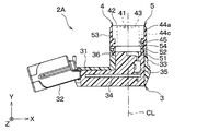
- the in-vehicle device has a cylindrical main body extending along the central axis and a protruding portion protruding from the main body in a direction intersecting the central axis, and is inserted into the through hole. It has a shaped part and a fixture for fixing the cylindrical part to the car body part by being sandwiched between the projecting portion and the car body part.
- the through hole has a vehicle body-side engaging portion that engages with a device-side engaging portion, which is an uneven portion provided on the tubular component, at a predetermined position in the circumferential direction surrounding the central position.
- each element may have a reference code in parentheses.
- the reference numeral indicates only an example of the correspondence between the same element and the specific configuration described in the embodiment described later. Therefore, the present disclosure is not limited to the description of the reference code.
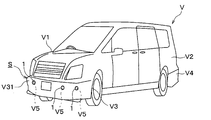
- FIG. 1C It is a perspective view which shows the appearance of the vehicle which has the vehicle-mounted structure which concerns on embodiment. It is a rear view which enlarges and shows the circumference of the mounting hole in the front bumper shown in FIG. 1A. It is a back view which shows the outline of the vehicle-mounted structure shown in FIG. 1A schematically. It is a rear view which shows the vehicle-mounted structure shown in FIG. 1C in an exploded manner. It is a top view of the corner sensor shown in FIG. 1C. It is a rear view of the corner sensor shown in FIG. 1C. It is a right side view of the corner sensor shown in FIG. 1C. It is a left side view of the corner sensor shown in FIG. 1C. It is a top view of the center sensor shown in FIG.
- FIG. 1C It is a top view which shows the schematic structure of the sensor main body shown in FIG. 1C and FIG. 1D. It is a left side view which shows the schematic structure of the sensor body shown in FIG. 1C and FIG. 1D. It is a partial cross-sectional view which shows the schematic structure of the sensor body shown in FIG. 1C and FIG. 1D. It is a front view which shows the schematic structure of the microphone case shown in FIG. It is an enlarged plan view which shows the anti-vibration spacer shown in FIG. 2A and FIG. 2E. It is a front view of the anti-vibration spacer shown in FIG. 6A.
- FIG. 7 is an enlarged plan view showing the corner bezel shown in FIG. 7A. It is a front view of the corner bezel shown in FIG. 8A. It is a right side view of the corner bezel shown in FIG. 8A. It is a rear view of the corner bezel shown in FIG. 8A. It is a cross-sectional view which shows the part of the bezel shown in FIG.
- FIG. 7B is an enlarged plan view showing the center bezel shown in FIG. 7B. It is a front view of the center bezel shown in FIG. 10A. It is a perspective view which looked at the center bezel shown in FIG. 10A from the back side. It is a rear view of the corner retainer shown in FIGS. 2A-2D. It is a right side view of the corner retainer shown in FIG. 11A. It is a top view of the corner retainer shown in FIG. 11A. It is a front view of the corner retainer shown in FIG. 11A. It is a rear view of the center retainer shown in FIG. 2E. It is a right side view of the center retainer shown in FIG. 12A. It is a top view of the center retainer shown in FIG. 12A. It is a front view of the center retainer shown in FIG. 12A.
- the ultrasonic sensor 1 as an in-vehicle device has a configuration as an in-vehicle clearance sonar. That is, the ultrasonic sensor 1 is configured to be mounted on the vehicle V so that it can detect an obstacle that is an object existing around the vehicle V.
- the ultrasonic sensor 1 has a transmission / reception integrated configuration capable of transmitting and receiving ultrasonic waves. That is, the ultrasonic sensor 1 transmits an ultrasonic exploration wave toward the external space of the vehicle V, receives a received wave including a reflected wave due to an obstacle of the exploration wave, and receives a reception result of the received wave. It is configured to generate and output a detection signal according to the above.
- the ultrasonic sensor 1 has a configuration having different directivity characteristics in the horizontal direction and the vertical vertical direction. That is, the ultrasonic sensor 1 is configured to radiate an exploration wave with a wide horizontal direction and a narrow vertical vertical direction.
- the "direction angle” refers to the generatrix and the directional axis in the elliptical cone when the range of -6 dB from the central sound pressure, which is the sound pressure on the directional axis, is represented by a substantially elliptical cone shape centered on the directional axis. It is the angle between the two, and is also called the "half-value angle".
- the “directional axis” is a virtual straight line extending from the ultrasonic sensor 1 toward the direction in which the exploration wave has the maximum sound pressure, and may also be referred to as a directional central axis or a detection axis.
- Vehicle V is a so-called four-wheeled vehicle, and has a box-shaped body V1.
- the vehicle body V1 has a vehicle body panel V2, a front bumper V3, and a rear bumper V4, which are plate-shaped vehicle body parts constituting the outer plate.
- the front bumper V3 is provided at the front end of the vehicle body V1.
- the rear bumper V4 is provided at the rear end of the vehicle body V1.
- the vehicle body panel V2, the front bumper V3, and the rear bumper V4 are formed of a metal plate material.
- the ultrasonic sensor 1 is configured to be attached to the front bumper V3 to detect objects existing in front of and to the front of the vehicle V. Similarly, the ultrasonic sensor 1 is configured to be attached to the rear bumper V4 to detect an object existing behind and to the rear side of the vehicle V.
- the state in which the ultrasonic sensor 1 is attached to the front bumper V3 or the rear bumper V4 is hereinafter referred to as "attached state”. Further, a state in which the ultrasonic sensor 1 is mounted on the vehicle V by being attached to the front bumper V3 or the rear bumper V4 provided on the vehicle body V1 is hereinafter referred to as an "vehicle-mounted state”.
- the “vehicle-mounted state” includes the “mounted state”. That is, the ultrasonic sensor 1 in the vehicle-mounted state also corresponds to the “mounted state”.
- the vehicle-mounted structure S according to the present embodiment is a structure in which an ultrasonic sensor 1 is attached to a front bumper V3 or a rear bumper V4, which are plate-shaped vehicle body parts.
- a plurality of (for example, four) ultrasonic sensors 1 are attached to the front bumper V3 in the vehicle-mounted state.
- the plurality of ultrasonic sensors 1 attached to the front bumper V3 are arranged at different positions in the vehicle width direction.
- a plurality of (for example, four) ultrasonic sensors 1 are attached to the rear bumper V4.
- the front bumper V3 and the rear bumper V4 are formed with mounting holes V5, which are through holes for mounting the ultrasonic sensor 1.
- the vehicle-mounted structure S formed by attaching the ultrasonic sensor 1 to the rear bumper V4 also has the same configuration as that of the present embodiment described below.
- the mounting hole V5 is provided so as to open toward the external space of the vehicle V at the bumper outer surface V31 by penetrating the front bumper V3 in the thickness direction thereof.
- the bumper outer surface V31 is the outer surface of the front bumper V3 and is provided so as to face the external space of the vehicle V in the vehicle-mounted state.
- FIG. 1B is an enlarged view of the mounting hole V5 as viewed from the bumper back surface V32 side, which is the back surface of the bumper outer surface V31.
- the mounting hole V5 is formed in the shape of a round hole having a columnar space inside. That is, the mounting hole V5 has an inner edge V51 having a cylindrical inner surface shape.
- the mounting hole V5 has a bumper-side engaging portion V52 as a vehicle body-side engaging portion in order to prevent erroneous mounting of the ultrasonic sensor 1.
- “Misinstallation” includes installing or attempting to install an ultrasonic sensor 1 having an incorrect part number or configuration that is different from the one that should be originally installed in the installation hole V5 in a specific vehicle V.
- one mounting hole V5 is provided with one bumper-side engaging portion V52.
- the bumper side engaging portion V52 is provided at a predetermined position in the circumferential direction surrounding the center position CP of the mounting hole V5.
- the center position CP is the position of the center point of the arc in the mounting hole V5 in the arc-shaped portion in the front view or the rear view other than the bumper side engaging portion V52.
- the center position CP is the center position of the arc forming the line of intersection between the inner edge V51 of the cylindrical inner surface in the mounting hole V5 and the outer surface V31 of the bumper or the back surface V32 of the bumper.
- the "circumferential direction" in the mounting hole V5 is the circumferential direction when it is assumed that the substantially circular mounting hole V5 is a perfect circle without the bumper side engaging portion V52.
- the position in the circumferential direction is hereinafter simply referred to as "circumferential position". The details of the "predetermined position" where the bumper-side engaging portion V52 is provided will be described later.
- "wrong mounting” includes mounting or attempting to mount an ultrasonic sensor 1 having the correct part number or configuration in a mounting posture different from the original one.
- the mounting posture is a posture relative to the front bumper V3 of the ultrasonic sensor 1 in the mounted state, and includes a mounting angle.
- the mounting angle is a rotational posture centered on the directional axis of the ultrasonic sensor 1 in the mounted state.
- the mounting posture in the vehicle-mounted state is also referred to as "vehicle-mounted posture”.
- the mounting angle in the vehicle-mounted state is the mounting angle around the directional axis of the ultrasonic sensor 1, and is also referred to as the “vehicle-mounted angle”.
- the bumper-side engaging portion V52 is provided so as to define a mounting angle, that is, an in-vehicle angle by engaging with a device-side engaging portion described later provided in the ultrasonic sensor 1.
- the bumper side engaging portion V52 is formed as a concavo-convex portion in which the hole diameter of the mounting hole V5, which is a through hole formed in a substantially circular shape, changes.
- the hole diameter of the mounting hole V5 is the distance from the center position CP of the mounting hole V5 to the inner edge V51. That is, the mounting hole V5 has a shape in which the bumper-side engaging portion V52, which is an uneven portion, is provided on the inner edge V51 of the round hole.
- the bumper-side engaging portion V52 has a bumper-side convex portion V53 and a pair of bumper-side concave portions V54.
- the bumper-side convex portion V53 is a convex portion projecting toward the inside of the mounting hole V5, and the tip portion in the projecting direction is formed in a rounded shape in the front view. Specifically, the bumper-side convex portion V53 is projected toward the center position CP at the inner edge V51 of the mounting hole V5.
- the bumper-side concave portion V54 is a portion formed in a relatively concave shape at both ends of the bumper-side convex portion V53 in the circumferential direction by providing the bumper-side convex portion V53, and has a rounded shape when viewed from the front. Is formed in. That is, the mounting hole V5 has a shape in which the diameter is reduced by the bumper-side convex portion V53 and the radius is constant at other portions.
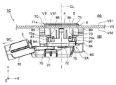
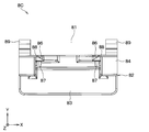
- FIGS. 1C and 1D are schematic views showing the vehicle-mounted structure S according to the present embodiment as viewed from the back surface V32 side of the bumper.
- the schematic configuration of the vehicle-mounted structure S according to the present embodiment will be described with reference to FIGS. 1C and 1D.
- the Cartesian coordinate system is set with reference to the gravitational action direction in the vehicle-mounted state.
- the present disclosure is not limited to specific examples of such Cartesian coordinate systems.
- the upward direction along the vertical upper direction is defined as the Z-axis positive direction.
- the vertical upper direction is a direction opposite to the gravitational action direction when the vehicle V is stably placed on a horizontal plane in a state where it can travel.
- the upward direction is the same direction as the vertically upper direction or the direction forming a predetermined small acute angle ⁇ with the vertically upper direction. ⁇ is, for example, 10 degrees or less. Therefore, depending on the shape of the front bumper V3 and the like, the Z-axis positive direction may be the same direction as the vertically upward direction, or may be a direction intersecting the vertically upward direction. Looking at a specific part of the vehicle V from the vertically upper side to the vertically lower part while the vehicle V is stably placed on a horizontal plane in a state where the vehicle V can travel is hereinafter referred to as "plan view". That is.
- FIGS. 1C and 1D parts of the front bumper V3 extending in the vehicle width direction other than the part to which the ultrasonic sensor 1 is attached are omitted. Further, for the convenience of illustration, the portion of the front bumper V3 to which the ultrasonic sensor 1 is attached is also shown so that the directional axis is orthogonal to the paper surface. Therefore, the X-axis direction in the figure is a horizontal direction along the vehicle width direction.
- the vehicle width direction is a direction orthogonal to the vehicle overall length direction and the vehicle height direction.
- the vehicle height direction is a direction parallel to the gravitational action direction when the vehicle V is stably placed on a horizontal plane in a state where it can travel.
- the vehicle total length direction is a direction that defines the total length of the vehicle V, and specifically, is a direction parallel to the direction in which the front bumper V3 and the rear bumper V4 are lined up in a plan view.
- the X-axis direction may not be parallel to the vehicle width direction in the actual vehicle-mounted state.
- the vehicle-mounted structure S is configured by attaching a corner sensor 1C and / or a center sensor 1T as an ultrasonic sensor 1 to a front bumper V3 as a vehicle body component to be attached.
- the front bumper V3 has a first mounting hole V501, a second mounting hole V502, a third mounting hole V503, and a fourth mounting hole V504.
- the first mounting hole V501 and the second mounting hole V502 are formed so that the corner sensor 1C can be mounted.
- the third mounting hole V503 and the fourth mounting hole V504 are formed so that the center sensor 1T can be mounted.
- the expression "mounting hole V5" is used when the first mounting hole V501, the second mounting hole V502, the third mounting hole V503, and the fourth mounting hole V504 are generically referred to without distinction, the expression "mounting hole V5" is used. Is used.
- the first mounting hole V501 and the second mounting hole V502 are symmetrically arranged with the vehicle center surface PC in between.
- the vehicle center surface PC is a virtual plane that is orthogonal to the vehicle width direction and passes through the center position in the vehicle width direction in the vehicle V with the front bumper V3 attached. That is, the vehicle center surface PC is parallel to the vehicle overall length direction and the vehicle height direction.
- the third mounting hole V503 and the fourth mounting hole V504 are symmetrically arranged with the vehicle central surface PC in between.
- the third mounting hole V503 and the fourth mounting hole V504 are arranged between the first mounting hole V501 and the second mounting hole V502.
- the first mounting hole V501, the third mounting hole V503, the fourth mounting hole V504, and the second mounting hole V502 are arranged in this order along the vehicle width direction.
- the first mounting hole V501, the second mounting hole V502, the third mounting hole V503, and the fourth mounting hole V504 have the same shape. That is, the first mounting hole V501, the second mounting hole V502, the third mounting hole V503, and the fourth mounting hole V504 have the same round hole diameter. Further, the first mounting hole V501, the second mounting hole V502, the third mounting hole V503, and the fourth mounting hole V504 have a bumper-side engaging portion V52, that is, a bumper-side convex portion V53 having the same shape. On the other hand, the circumferential positions of the bumper-side engaging portion V52 of the first mounting hole V501, the second mounting hole V502, the third mounting hole V503, and the fourth mounting hole V504 are set to be different from each other.
- the circumferential position of the bumper-side engaging portion V52 is indicated by an azimuth angle based on the direction from the center position CP to the positive direction of the Z axis in the drawing.
- the direction from the center position CP toward the Z-axis positive direction in the drawing is set as the reference direction, that is, 0 degree, and the direction from the center position CP toward the center in the circumferential direction of the bumper side engaging portion V52 becomes larger in the clockwise direction.
- the first mounting hole V501 corresponding to the first through hole is formed so that the circumferential position of the bumper side engaging portion V52 is the first position ⁇ 1.
- the second mounting hole V502 corresponding to the second through hole is formed so that the circumferential position of the bumper-side engaging portion V52 is the second position ⁇ 2.
- the third mounting hole V503 corresponding to the third through hole is formed so that the circumferential position of the bumper-side engaging portion V52 is the third position ⁇ 3.
- the fourth mounting hole V504 corresponding to the fourth through hole is formed so that the circumferential position of the bumper-side engaging portion V52 is the fourth position ⁇ 4.
- the first position ⁇ 1 is set to 225 degrees.
- the second position ⁇ 2 is set to 45 degrees. That is, the first position ⁇ 1 and the second position ⁇ 2 are set to a difference of 180 degrees so as to be symmetrical with respect to the central position CP.
- the third position ⁇ 3 is set to 135 degrees.
- the fourth position ⁇ 4 is set to 315 degrees. That is, the third position ⁇ 3 and the fourth position ⁇ 4 are set to a difference of 180 degrees so as to be symmetrical with respect to the central position CP.
- the corner sensor 1C corresponding to the first in-vehicle device is mounted on the first mounting hole V501 and the second mounting hole V502 so that the front bumper V3 is arranged at a position closer to both ends in the vehicle width direction. ..
- the corner sensor 1C is configured so that the mounting posture is the first posture when mounted in the first mounting hole V501.
- the first posture is a mounting posture in which the connector extension direction DC faces the negative direction side of the X axis in the drawing.
- the definition of the connector extension direction DC will be described later.
- the corner sensor 1C is configured so that when it is mounted in the second mounting hole V502, the mounting posture is a second posture different from the first posture.
- the second posture is a mounting posture in which the connector extension direction DC faces the positive direction side of the X axis in the drawing. That is, the second posture is a mounting posture in which the mounting angle differs from the first posture by 180 degrees.
- the connector extension direction DC is opposite to the X-axis direction in the drawing. It is configured in.
- the pair of corner sensors 1C are attached to the front bumper V3 so that the connector extension direction DC faces the outside in the vehicle width direction.
- the corner sensor 1C mounted on the first mounting hole V501 and the corner sensor 1C mounted on the second mounting hole V502 are arranged so that the mounting postures are symmetrical with respect to the vehicle center surface PC. ..
- the center sensor 1T corresponding to the second in-vehicle device is mounted in the third mounting hole V503 and the fourth mounting hole V504 so as to be arranged at a position closer to the center in the vehicle width direction of the front bumper V3. ..
- the center sensor 1T is configured so that the mounting posture is the third posture when mounted in the third mounting hole V503.
- the center sensor 1T is configured so that when it is mounted in the fourth mounting hole V504, the mounting posture is a fourth posture different from the third posture.
- the third posture is the mounting posture in which the connector extension direction DC faces the positive direction side of the X axis in the figure. That is, the third posture is a mounting posture in which the mounting angle is the same as that of the second posture.
- the fourth posture is a mounting posture in which the connector extension direction DC faces the negative direction side of the X axis in the drawing. That is, the fourth posture is a mounting posture in which the mounting angle differs from the third posture by 180 degrees.
- the fourth posture is a mounting posture in which the mounting angle is the same as that of the first posture.
- the center sensor 1T is mounted in the third mounting hole V503 and in the fourth mounting hole V504 so that the connector extension direction DC is opposite to the X-axis direction in the drawing. It is configured in.
- the pair of center sensors 1T are attached to the front bumper V3 so that the connector extension direction DC faces inward in the vehicle width direction.
- the center sensor 1T mounted on the third mounting hole V503 and the center sensor 1T mounted on the fourth mounting hole V504 are arranged so that the mounting postures are symmetrical with respect to the vehicle center surface PC. ..
- the corner sensor 1C includes a sensor body 2A and a first component group 2C.
- the sensor body 2A is configured to be mounted in the first mounting hole V501 and the second mounting hole V502 in the front bumper V3 by using the first component group 2C.
- the center sensor 1T includes a sensor body 2A and a second component group 2T.
- the sensor body 2A is configured to be mounted in the third mounting hole V503 and the fourth mounting hole V504 in the front bumper V3 by using the second component group 2T.
- the corner sensor 1C constitutes the sensor body 2A, the sensor case 3, the ultrasonic microphone 4, the cushion member 5, the anti-vibration spacer 6, and the first component group 2C. , Bezel 7 and retainer 8.
- the bezel 7 and retainer 8 constituting the first component group 2C are hereinafter referred to as “corner bezel 7C” and “corner retainer 8C”.
- the center sensor 1T has the same configuration as the corner sensor 1C except that the second component group 2T is provided in place of the first component group 2C.
- the bezel 7 and retainer 8 constituting the second component group 2T are hereinafter referred to as “center bezel 7T” and “center retainer 8T".
- center bezel 7T and “center retainer 8T”.
- the expression “bezel 7” is used when the corner bezel 7C and the center bezel 7T are generically referred to without distinction. The same applies to the retainer 8.
- the corner sensor 1C and the center sensor 1T are configured so that the retainer mounting direction DS is the same direction, that is, the Z-axis direction in the drawing.
- the retainer mounting direction DS is a direction in which the retainer 8 is relatively close to the secondary assembly inserted through the mounting hole V5 when the ultrasonic sensor 1 is mounted on the front bumper V3.
- the secondary assembly is an assembly in which the anti-vibration spacer 6 and the bezel 7 are further assembled to the sensor body 2A, which is a primary assembly in which the ultrasonic microphone 4 and the cushion member 5 are assembled to the sensor case 3. ..
- the state in which such a secondary assembly is formed may be hereinafter referred to as an "assembled state".
- the "mounted state” and "vehicle-mounted state” also correspond to the "assembled state”.
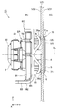
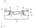
- FIG. 2E shows the center sensor 1T mounted in the fourth mounting hole V504 shown in FIG. 1D in an in-vehicle state.
- a right-handed XYZ Cartesian coordinate system is set with reference to the gravitational action direction in the vehicle-mounted state, as shown in FIGS. 2A and after. It is assumed that the Z-axis positive direction in the right-handed XYZ coordinate system shown in FIGS. 2A and later coincides with the Z-axis positive direction shown in FIGS. 1C and 1D.
- the positive Y-axis direction in the right-handed XYZ coordinate system is parallel to the thickness direction of the front bumper V3 at the mounting position, and is the direction from the bumper inner space SN to the bumper outer space SG.
- the “mounting position” is a position where the ultrasonic sensor 1 is mounted on the front bumper V3, and is typically the center position CP of the mounting hole V5.
- the bumper outer space SG is a space facing the bumper outer surface V31 and being outside the vehicle V in the vehicle-mounted state.
- the bumper interior space SN is a space that faces the bumper back surface V32 and is inside the vehicle V in the vehicle-mounted state.
- the X-axis direction in the right-handed XYZ coordinate system is orthogonal to the thickness direction of the front bumper V3 at the mounting position and is horizontal in the vehicle-mounted state.
- the X-axis positive direction in the right-handed XYZ coordinate system is assumed to substantially coincide with the X-axis positive direction shown in FIGS. 1C and 1D, or to form a predetermined small acute angle. That is, the X-axis direction in the right-handed XYZ coordinate system is a horizontal direction along the vehicle width direction, similar to the X-axis direction shown in FIGS. 1C and 1D.
- the direction parallel to the central axis CL constituting the directional axis of the ultrasonic sensor 1 is referred to as "axial direction”.
- the one on the positive direction side of the Y axis is referred to as the "tip portion in the axial direction”
- the one on the negative direction side of the Y axis is referred to.
- the base end in the axial direction is usually referred to as "axial dimension” below.
- any direction orthogonal to the axial direction is referred to as an "in-plane direction”.
- the shape of a certain member or part in a plane orthogonal to the central axis CL may be referred to as an "in-plane shape”.
- the "in-plane direction” includes a “diameter direction” and a “axial circumferential direction”.
- the "diameter direction” is a direction extending radially from the central axis CL. That is, the "diameter direction” is a direction that is orthogonal to the central axis CL and is separated from the central axis CL.
- the "diameter direction” is the direction in which the half straight line extends when a half straight line is drawn in the virtual plane starting from the intersection of the virtual plane orthogonal to the central axis CL and the central axis CL. ..
- the "diameter direction” is the radial direction of the virtual circle when a virtual circle is drawn in the virtual plane around the intersection of the virtual plane and the central axis CL.
- the "axial direction” is the circumferential direction of the virtual circle surrounding the central axis CL. The position in the axial direction is simply referred to as "axial position" below.
- the central axis CL is substantially parallel to the thickness direction of the front bumper V3 at the mounting position or a portion in the vicinity thereof. It is mounted on the vehicle V so as to be.
- the center sensor 1T is mounted on the vehicle V so that the center axis CL intersects the thickness direction of the front bumper V3 at the mounting position or a portion in the vicinity thereof in the vehicle-mounted state. It is installed.
- the sensor main body 2A which forms the main body portion of the ultrasonic sensor 1, includes a sensor case 3, an ultrasonic microphone 4, and a cushion member 5.
- the sensor body 2A is attached to the front bumper V3 by using the anti-vibration spacer 6, the bezel 7, and the retainer 8.
- the anti-vibration spacer 6 the bezel 7, and the retainer 8.
- (Sensor case) 3A and 3B show a state in which the retainer 8 is removed from the ultrasonic sensor 1 in the mounted state, the secondary assembly is taken out to the outside space SG side of the bumper, and then the bezel 7 is further removed from the secondary assembly.
- a sensor case 3 constituting a housing of an ultrasonic sensor 1, that is, a sensor body 2A, has a box-shaped portion 31, a connector portion 32, and a microphone support portion 33. ..
- the sensor case 3 is integrally formed of a hard synthetic resin such as polybutylene terephthalate, ABS resin, polypropylene, polycarbonate, and polystyrene.
- the box-shaped portion 31 is formed in a box shape having a longitudinal direction along the horizontal direction and a width direction along the vertical vertical direction and having a thin outer shape in the axial direction in the mounted state.
- the connector portion 32 is in the vehicle-mounted state in the connector extending direction DC, that is, substantially horizontal. Moreover, it extends diagonally backward. That is, the connector portion 32 is provided so as to be separated from the front bumper V3 in the mounted state toward the connector extension direction DC.
- the connector unit 32 has a configuration as a receptacle connector that can be attached to and detached from a plug connector (not shown) provided at the end of a wire harness for electrical connection with an external device such as an ECU.
- ECU is an abbreviation for Electronic Control Unit.
- the microphone support portion 33 extends axially from the other end of the box-shaped portion 31 in the longitudinal direction (that is, the right end in FIG. 3A).
- the microphone support portion 33 has a tubular shape that surrounds the central axis CL.
- the microphone support portion 33 is formed in a cylindrical shape with the central axis CL as the axis center.
- the circuit board 34 is housed inside the box-shaped portion 31.
- the circuit board 34 is electrically connected to the ultrasonic microphone 4 via the connection wiring 35.
- a cushion locking protrusion 36 and a bezel locking protrusion 37 are provided at the tip of the microphone support portion 33 in the axial direction.
- the cushion locking projection 36 is a projection protruding from the inner wall surface of the cylindrical inner surface surrounding the central axis CL in the microphone support portion 33 toward the central axis CL, and extends in the axial direction.
- the bezel locking projection 37 is a small projection protruding in the radial direction from the cylindrical outer wall surface surrounding the central axis CL in the microphone support portion 33, and is detachably engaged with the bezel 7 in the assembled state. It is formed to do.
- the microphone support portion 33 is provided with a plurality of bezel locking projections 37 at substantially the same position in the axial direction and different positions in the axial direction, respectively. Specifically, four bezel locking projections 37 are arranged at equal intervals in the axial circumferential direction.
- the pair of bezel locking projections 37 that are axially symmetrical with respect to the central axis CL are provided so that the virtual straight lines passing through them form an angle of 45 degrees with the X-axis and the Z-axis.
- An angle defining protrusion 38 is provided at the base end portion of the microphone support portion 33 in the axial direction.
- the angle defining protrusion 38 is a protrusion larger than the bezel locking protrusion 37, which is projected in the radial direction from the outer wall surface of the microphone support portion 33, and is provided at a predetermined position in the axial circumferential direction. There is.
- the ultrasonic microphone 4 has a columnar outer shape extending along the axial direction. Specifically, in the present embodiment, the ultrasonic microphone 4 is formed in a substantially columnar shape centered on the central axis CL.
- the ultrasonic microphone 4 includes an ultrasonic element 41 and a microphone case 42.
- the ultrasonic element 41 is a so-called electro-mechanical conversion element, and is formed of a thin-film piezoelectric element or the like.
- the ultrasonic element 41 is housed inside the microphone case 42.
- the microphone case 42 that constitutes the housing of the ultrasonic microphone 4 is formed in a bottomed cylindrical shape by a metal material such as aluminum.
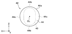
- the microphone case 42 has a diaphragm 43 and a side plate portion 44.
- the diaphragm 43 is formed in a thin plate shape having a thickness direction in the axial direction.
- the diaphragm 43 is provided so as to close the tip portion of the side plate portion 44 in the axial direction.
- the outer surface of the diaphragm 43 facing the bumper outer space SG in the mounted state or in the vehicle-mounted state is formed in a smooth flat shape.
- the ultrasonic element 41 is fixed to the inner surface of the diaphragm 43 on the back side of the outer surface.
- the diaphragm 43 is formed so that the in-plane shapes have a longitudinal direction and a lateral direction that are substantially orthogonal to each other. Specifically, in response to the above-mentioned directivity characteristics of the ultrasonic sensor 1, the diaphragm 43 has an oval or elliptical in-plane shape having a longitudinal direction along the vertical vertical direction in an in-vehicle state. doing.
- the side plate portion 44 is a substantially cylindrical portion of the microphone case 42 and extends in the axial direction.
- the side plate portion 44 that is, the side surface 44a forming the outer wall surface of the ultrasonic microphone 4 is formed in a cylindrical surface shape centered on the central axis CL.
- the side plate portion 44 has a thin-walled portion 44b and a thick-walled portion 44c.
- the thin-walled portion 44b is provided at a position corresponding to both ends of the diaphragm 43 in the longitudinal direction.
- the pair of thin-walled portions 44b are arranged symmetrically with the central axis CL in between while being arranged substantially vertically in the vertical direction in the vehicle-mounted state.
- the thick portion 44c is provided at a position corresponding to both ends of the diaphragm 43 in the lateral direction.
- the pair of thick portions 44c are arranged symmetrically with the central axis CL in between while being arranged in a substantially horizontal direction in a vehicle-mounted state.
- a pair of engaging grooves 45 are formed in the side plate portion 44.
- the engagement groove 45 is a square groove extending parallel to the Z-axis direction in the drawing, and is provided in the thick portion 44c.
- the pair of engaging grooves 45 are symmetrically arranged with the central axis CL in between.
- the cushion member 5 which is a vibration absorber is seamlessly and integrally formed of a synthetic resin-based elastic material such as silicone rubber.
- the cushion member 5 is provided on the sensor main body 2A, which is a primary assembly, as a component constituting the sensor main body 2A together with the ultrasonic microphone 4.
- the cushion member 5 is formed in a cylindrical shape surrounding the central axis CL. Specifically, in the present embodiment, the cushion member 5 has substantially the same outer diameter as the outer diameter of the microphone support portion 33 and substantially the same outer diameter as the outer diameter of the side plate portion 44 with the central axis CL as the axis center. It has a substantially cylindrical shape with an inner diameter. Further, the cushion member 5 is formed to have a larger axial dimension than the ultrasonic microphone 4.
- the cushion member 5 is fixed to the microphone support portion 33 at the supported portion 51 which is the base end portion in the axial direction.
- the supported portion 51 is provided with a locking groove 52 that opens in the radial direction.
- the locking groove 52 is a groove having a shape that engages with the cushion locking projection 36 provided on the microphone support portion 33, and extends in the axial direction.
- the microphone accommodating portion 53 which is a portion of the cushion member 5 on the tip side in the axial direction with respect to the supported portion 51, is configured to accommodate the ultrasonic microphone 4 over almost the entire axial direction. That is, the microphone accommodating portion 53 has a columnar internal space corresponding to the outer shape of the ultrasonic microphone 4 so as to cover the side surface 44a of the ultrasonic microphone 4.
- the microphone accommodating portion 53 is provided with a pair of engaging protrusions 54.
- the pair of engaging protrusions 54 are arranged so as to face each other with the central axis CL interposed therebetween.
- the engaging protrusion 54 has a shape that fits with the engaging groove 45, which is a square groove, and is a rectangular ridge portion in a cross-sectional view that protrudes toward the central axis CL, and is in the Z-axis direction in the drawing. It has been extended.
- the cushion member 5 is provided so as to elastically support the ultrasonic microphone 4 on the tip end side in the axial direction while being fixed to the sensor case 3 on the proximal end side in the axial direction. That is, the ultrasonic sensor 1 in the present embodiment elastically supports the ultrasonic microphone 4 on the sensor case 3 via the cushion member 5, thereby transmitting vibration between the sensor case 3 and the ultrasonic microphone 4. It is configured to suppress.
- the cushion member 5 is provided in the ultrasonic sensor 1 so as to be interposed between the bezel 7 provided so as to surround the side surface 44a of the ultrasonic microphone 4 and the ultrasonic microphone 4 in the vehicle-mounted state. .. That is, the cushion member 5 is configured to be interposed between the ultrasonic microphone 4 and the front bumper V3 to suppress vibration transmission between the ultrasonic microphone 4 and the front bumper V3.
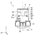
- the microphone accommodating portion 53 in the cushion member 5 has a tip portion 55, a first tubular portion 56, and a second tubular portion 57.
- the tip portion 55, the first cylindrical portion 56, and the second tubular portion 57 are arranged in this order in the axial direction.
- the tip portion 55 is a portion of the cushion member 5 on the most tip side in the axial direction, and has a conical outer wall surface and a cylindrical inner wall surface whose outer diameter decreases toward the tip end side in the axial direction. It is formed in a tapered shape with.
- the first cylindrical portion 56 is a portion adjacent to the tip portion 55 in the axial direction, and is provided on the tip side of the cushion member 5 in the axial direction.
- the first cylindrical portion 56 is configured to be sandwiched between the ultrasonic microphone 4 and the bezel 7 while being in contact with the ultrasonic microphone 4 and the bezel 7. That is, the first cylindrical portion 56 has a maximum thickness substantially the same as the dimension of the gap between the side surface 44a of the ultrasonic microphone 4 and the bezel 7 in the assembled state.
- the first tubular portion 56 is formed in a cylindrical shape having a constant thickness, that is, a radial dimension. In other words, the first cylindrical portion 56 is provided so as to abut the ultrasonic microphone 4 and the bezel 7 over the entire axial direction.
- the second tubular portion 57 is provided so as to be adjacent to the first tubular portion 56 on the proximal end side in the axial direction.
- the second cylindrical portion 57 has a pair of recesses 57a that open in the radial direction.
- the pair of recesses 57a are provided symmetrically with the central axis CL in between.
- the second cylindrical portion 57 is provided with a large diameter portion 58 and a small diameter portion 59.
- the large diameter portion 58 is provided so as to be sandwiched between the ultrasonic microphone 4 and the bezel 7 while being in contact with the ultrasonic microphone 4 and the bezel 7.
- the large diameter portion 58 has a partial cylindrical shape having a maximum thickness substantially equal to the dimension of the gap between the side surface 44a of the ultrasonic microphone 4 and the bezel 7 in the assembled state.
- the large diameter portion 58 is formed so that the diameters of the inner wall surface and the outer wall surface centered on the central axis CL substantially coincide with those of the first cylindrical portion 56.
- the small diameter portion 59 is provided so as to be adjacent to the large diameter portion 58 in the circumferential direction, and the outer diameter centered on the central axis CL is smaller than that of the large diameter portion 58.
- the small diameter portion 59 is formed to be thinner than the large diameter portion 58 by providing the recess 57a in the second tubular portion 57, and is provided at a position corresponding to the recess 57a in the axial direction. That is, the small diameter portion 59 is formed so that the gap with the bezel 7 is larger than that of the large diameter portion 58.
- the small diameter portion 59 is provided so that the diameter of the inner wall surface centered on the central axis CL is substantially the same as that of the first cylindrical portion 56.
- a pair of large diameter portions 58 are arranged so as to face each other with the central axis CL in between.
- a pair of small diameter portions 59 are arranged so as to face each other with the central axis CL in between. That is, one of the pair of large diameter portions 58, one of the pair of small diameter portions 59, the other one of the pair of large diameter portions 58, and the other one of the pair of small diameter portions 59. The ones are arranged adjacent to each other in this order in the axial circumferential direction.
- the cushion member 5 is configured such that the arrangement direction of the pair of large diameter portions 58 sandwiching the central axis CL and the arrangement direction of the pair of small diameter portions 59 sandwiching the central axis CL are orthogonal to each other. ..
- the large diameter portion 58 is formed so that the length in the axial circumferential direction is shorter than that of the small diameter portion 59. Further, as is clear from the illustrations in FIGS. 3A to 5, the large diameter portion 58 is provided at a position corresponding to both ends of the diaphragm 43 in the lateral direction. On the other hand, the small diameter portion 59 is provided at a position corresponding to both ends of the diaphragm 43 in the longitudinal direction.
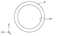
- the anti-vibration spacer 6 is a thin plate-shaped and ring-shaped member having a thickness direction in the axial direction, and is formed of a synthetic resin-based elastic material such as silicone rubber. Specifically, in the present embodiment, the anti-vibration spacer 6 has a shape in which a spacer through hole 61, which is a circular through hole, is formed at the center position of the disk-shaped member.
- the anti-vibration spacer 6 has the flange portion 71 and the front bumper V3 described later in the bezel 7 in the vehicle-mounted state so as to suppress the vibration transmission between the bezel 7 and the front bumper V3. It is provided between. That is, the anti-vibration spacer 6 is sandwiched between the back surface 71a, which is the surface of the flange portion 71 facing the front bumper V3, and the bumper outer surface V31 so as to be interposed between the bezel 7 and the front bumper V3 in the mounted state. Has been done.
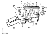
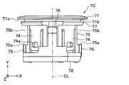
- FIG. 7A shows a secondary assembly provided in the corner sensor 1C shown in FIG. 2A.
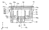
- FIG. 7B shows a secondary assembly provided in the center sensor 1T shown in FIG. 2E.
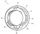
- 8A-8D show the schematic configuration of the corner bezel 7C shown in FIG. 7A.
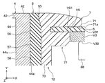
- FIG. 9 is an enlarged cross-sectional view of the periphery of the flange portion 71 of the bezel 7 in the mounted state or the vehicle-mounted state.
- 10A-10C show the schematic configuration of the center bezel 7T shown in FIG. 7B.
- the bezel 7 is a component used for attaching an ultrasonic sensor 1 to a front bumper V3, which is a plate-shaped vehicle body component, and is integrally formed of a hard synthetic resin.
- the bezel 7 is inserted into the mounting hole V5 shown in FIG. 1B or the like in the mounted state.
- the corner bezel 7C sets the mounting posture of the corner sensor 1C to the first posture by engaging with the bumper-side engaging portion V52 provided in the first mounting hole V501. It is configured as follows. Further, the corner bezel 7C is configured to set the mounting posture of the corner sensor 1C to the second posture by engaging with the bumper-side engaging portion V52 provided in the second mounting hole V502.
- the center bezel 7T is configured to set the mounting posture of the center sensor 1T to the third posture by engaging with the bumper-side engaging portion V52 provided in the third mounting hole V503. Further, the center bezel 7T is configured to set the mounting posture of the center sensor 1T to the fourth posture by engaging with the bumper side engaging portion V52 provided in the fourth mounting hole V504.
- a flange portion 71 is provided at the tip portion of the corner bezel 7C in the axial direction.
- the flange portion 71 is a ring-shaped portion having a thickness direction in the axial direction, and projects in the radial direction.
- the corner bezel 7C is formed so that the normal direction of the back surface 71a of the flange portion 71 is substantially parallel to the central axis CL.
- the flange portion 71 is formed in the shape of a disk having a circular through hole formed at the center position.
- the flange portion 71 has an outer diameter larger than the inner diameter of the mounting hole V5. That is, as shown in FIG. 2A and the like, the flange portion 71 is provided so as to face the peripheral portion of the mounting hole V5 on the bumper outer surface V31 with the anti-vibration spacer 6 interposed therebetween, as shown in FIG. 2A and the like. There is.
- the flange portion 71 has an inner diameter substantially the same as the outer diameter of the tip portion 55 of the cushion member 5. That is, as shown in FIG. 9, the flange portion 71 is configured to sandwich the tip portion 55 of the cushion member 5 with the side surface 44a of the microphone case 42.
- a spacer accommodating groove 71b for accommodating the anti-vibration spacer 6 is provided so as to open in the radial direction at a position adjacent to the flange portion 71 on the proximal end side of the flange portion 71 in the axial direction.
- the spacer accommodating groove 71b is formed so as to have a width, that is, an axial dimension corresponding to the thickness of the anti-vibration spacer 6, and a depth, that is, a radial dimension corresponding to the diameter of the spacer through hole 61 in the anti-vibration spacer 6. There is.
- the spacer accommodating groove 71b extends over the entire bezel 7 in the axial direction.
- the spacer accommodating groove 71b is provided between the flange portion 71 and the cylindrical portion 72. That is, the flange portion 71 protrudes in the radial direction at one end portion, that is, the tip portion of the cylindrical portion 72 extending in the axial direction.
- the flange portion 71 and the tubular portion 72 are seamlessly integrally formed of the same material.
- the tubular portion 72 is configured to be housed in the mounting hole V5 while surrounding the ultrasonic microphone 4 and the cushion member 5 in the assembled state and the mounting state.
- the tubular portion 72 has an outer diameter slightly smaller than the inner diameter of the mounting hole V5 and an inner diameter slightly larger than the outer diameter of the microphone support portion 33.
- the main body portion 73 which is a tubular portion including the central portion in the axial direction of the tubular portion 72, extends along the central axis CL.
- the sensor locking piece 74 is provided on the main body 73.
- the sensor locking piece 74 is a cantilever-shaped tongue piece having a thickness direction in the radial direction, and extends from the tip end portion to the base end portion in the axial direction of the main body portion 73. That is, the sensor locking piece 74 is formed so as to be elastically deformable in such a manner that the tip portion in the axial direction is a fixed end and the base end portion in the axial direction is a free end, and the free end moves in the radial direction.
- the sensor locking piece 74 in the corner bezel 7C extends in a direction substantially parallel to the normal direction of the back surface 71a of the flange portion 71.
- a locking hole 74a that penetrates the sensor locking piece 74 in the thickness direction is provided on the free end side of the sensor locking piece 74.
- the locking hole 74a is formed so as to be detachably engaged with the bezel locking projection 37 provided on the microphone support portion 33 in the assembled state.
- the main body 73 is provided with the same number of sensor locking pieces 74 as the bezel locking projections 37 so as to be arranged in the axial circumferential direction. That is, in the present embodiment, the four sensor locking pieces 74 are arranged at equal intervals in the axial circumferential direction.
- the plurality of sensor locking pieces 74 provided on the corner bezel 7C are formed to have the same length, that is, the axial dimension.
- the main body 73 is provided with a projecting portion 75.
- the projecting portion 75 projects from the main body portion 73 in a direction intersecting the central axis CL.
- the projecting portion 75 is integrally connected to the main body portion 73.
- the main body portion 73 and the projecting portion 75 are seamlessly integrally formed of the same material.
- the bezel 7 is provided with a pair of projecting portions 75.
- the pair of projecting portions 75 are arranged symmetrically with respect to the central axis CL. That is, each of the pair of projecting portions 75 projects in the direction opposite to the central axis CL.
- Each of the pair of projecting portions 75 is arranged between the two sensor locking pieces 74 in the axial circumferential direction.
- the protruding portion 75 is projected along the protruding direction of the flange portion 71.
- each of the pair of projecting portions 75 projects in the radial direction from the base end portion in the axial direction of the main body portion 73.
- the retainer contact surface 75a which is the end surface of the projecting portion 75 on the distal end side in the axial direction, is formed in a smooth planar shape having a normal direction parallel to the central axis CL. That is, the retainer contact surface 75a is provided so as to be substantially parallel to the back surface 71a of the flange portion 71.
- a retainer insertion groove 75b is formed on the tip side in the axial direction from the retainer contact surface 75a.
- the retainer insertion groove 75b is a space through which the retainer 8 is inserted when the ultrasonic sensor 1 is attached to the front bumper V3, and is provided so as to open in the radial direction. That is, the projecting portion 75 is formed so as to sandwich the retainer 8 inserted into the retainer insertion groove 75b with the bumper back surface V32 in the mounted state.
- the pair of retainer insertion grooves 75b are arranged symmetrically with respect to the central axis CL.
- Each of the pair of retainer insertion grooves 75b has a square groove-like structure extending in the Z-axis direction in the drawing. That is, as shown in FIG. 1D, the projecting portion 75 is formed so as to define the attachment / detachment direction of the retainer 8 which is the fixture in the present disclosure with respect to the bezel 7 in a direction parallel to the Z axis in the drawing. There is.
- a temporary assembly piece 76 is provided on the tubular portion 72.
- the temporary assembly piece 76 is a cantilever-shaped tongue piece having a thickness direction in the radial direction, and extends axially from the base end portion in the axial direction of the tubular portion 72 toward the flange portion 71. There is. That is, the temporary assembly piece 76 is formed so as to be elastically deformable in such a manner that the base end portion in the axial direction is a fixed end and the tip end portion in the axial direction is a free end, and the free end moves in the radial direction.
- the bezel 7 is provided with a pair of temporary assembly pieces 76.
- the pair of temporary assembly pieces 76 are arranged symmetrically with respect to the central axis CL.
- the bezel 7 is configured such that the arrangement direction of the pair of temporary assembly pieces 76 sandwiching the central axis CL is orthogonal to the arrangement direction of the pair of projecting portions 75 sandwiching the central axis CL. ..
- Each of the pair of temporary assembly pieces 76 is arranged between the two sensor locking pieces 74 in the axial circumferential direction. That is, the first sensor locking piece 74, the first projecting portion 75, the second sensor locking piece 74, the first temporary assembly piece 76, and the third sensor engagement.
- the stop piece 74 and the second projecting portion 75 are arranged at equal intervals in the axial circumferential direction in this order. Further, the second projecting portion 75, the fourth sensor locking piece 74, the second temporary assembly piece 76, and the first sensor locking piece 74 are arranged in this order in the axial circumferential direction. Are evenly spaced.
- a temporary assembly protrusion 76a protruding in the radial direction is provided at the free end of the temporary assembly piece 76, that is, the tip portion in the axial direction.
- the temporary assembly protrusion 76a is configured so that the secondary assembly can be held in the temporary assembly state.
- the temporary assembly state is a state in which the bezel 7 in the secondary assembly is inserted into the mounting hole V5, so that the secondary assembly is temporarily held by the front bumper V3 in a predetermined temporary assembly posture.
- the anti-vibration spacer 6 contacts or approaches the bumper outer surface V31 of the front bumper V3, and the connector portion 32 is rear-viewed along the X-axis direction in the drawing as shown in FIG. 1D.
- the posture of the secondary assembly is such that it extends.
- the temporarily assembled state corresponds to a state in which the retainer 8 is removed from the ultrasonic sensor 1 in the vehicle-mounted state.
- the temporary assembly projection 76a has a wedge-shaped outer shape having an inclined surface 76b and a flange facing surface 76c.
- the inclined surface 76b is a surface of the temporary assembly projection 76a that is exposed in the radial direction, and is provided so as to be separated from the central axis CL toward the tip end side in the axial direction.
- the flange facing surface 76c is an end surface of the temporary assembly projection 76a and is provided so as to face the back surface 71a of the flange portion 71.
- the tip-side projecting portion 77 is projected in the radial direction while being integrally connected to the main body 73.
- the tip-side projecting portion 77 is the most tip-side portion of the tubular portion 72 in the axial direction, and extends in the axial circumferential direction.
- the main body portion 73 and the tip-side projecting portion 77 are seamlessly and integrally formed of the same material. As shown in FIG. 9, the tip-side projecting portion 77 is provided so as to be in close contact with the inner edge V51 of the mounting hole V5 in the mounted state.
- the tip side projecting portion 77 is provided between the spacer accommodating groove 71b and the retainer insertion groove 75b in the axial direction. That is, the tip-side projecting portion 77 is provided so as to be adjacent to the spacer accommodating groove 71b and the retainer insertion groove 75b in the axial direction. Therefore, the spacer accommodating groove 71b is formed so as to include a gap between the flange portion 71 and the tip-side projecting portion 77. Further, the retainer insertion groove 75b is formed by a space between the projecting portion 75 and the tip-side projecting portion 77.
- the tip-side protruding portion 77 has a bezel-side engaging portion 77a as a device-side engaging portion.
- the bezel-side engaging portion 77a is formed so as to engage with the bumper-side engaging portion V52 shown in FIG. 1D as the vehicle body-side engaging portion. That is, the bezel-side engaging portion 77a is an uneven portion provided on the bezel 7 and has a shape corresponding to the shape of the bumper-side engaging portion V52.
- the bezel-side engaging portion 77a in the corner bezel 7C has a position in the axial circumferential direction in the assembled state on the Z-axis negative direction side of the two bezel locking projections 37 arranged on the connector portion 32 side of the central axis CL. It is provided so that it is in a position corresponding to the one. That is, as shown in FIG. 1D, the bezel-side engaging portion 77a in the corner bezel 7C engages with the bumper-side engaging portion V52 provided in the first mounting hole V501 to cause the corner sensor 1C to engage. It is formed at a position where the mounting posture is the first posture. Further, the bezel-side engaging portion 77a is formed at a position where the mounting posture in the corner sensor 1C becomes the second posture by engaging with the bumper-side engaging portion V52 provided in the second mounting hole V502. There is.
- the bezel-side engaging portion 77a has a bezel-side concave portion 77b and a pair of bezel-side convex portions 77c.
- the bezel-side concave portion 77b has a shape corresponding to the bumper-side convex portion V53. That is, the bezel-side recess 77b is a recess that opens in the radial direction, and is provided at a predetermined position in the axial direction of the tip-side projecting portion 77 extending in the axial direction.
- the bezel-side convex portion 77c has a shape corresponding to the bumper-side concave portion V54.
- the bezel-side convex portion 77c is a portion formed in a relatively convex shape at both ends of the bezel-side concave portion 77b in the axial direction by providing the bezel-side concave portion 77b.
- An angle-regulating recess 78 is formed in the cylindrical portion 72.
- the angle defining recess 78 is provided so as to open in the axial direction at the position closest to the proximal end side in the axial direction of the tubular portion 72. Further, the angle defining recess 78 is provided at the innermost position in the radial direction of the tubular portion 72 so as to open toward the central axis CL.
- the angle defining recess 78 has a concave shape corresponding to the convex shape of the angle defining protrusion 38 so as to accommodate the angle defining protrusion 38 provided on the microphone support portion 33 in the assembled state.
- angle defining recess 78 there is only one angle defining recess 78 at a predetermined position in the axial circumferential direction of the cylindrical portion 72 so as to define the relative rotation angle of the bezel 7 with respect to the sensor case 3 about the central axis CL in the assembled state. It is provided. Specifically, in the present embodiment, the angle defining recess 78 is arranged at a position corresponding to one of the four sensor locking pieces 74 in the axial circumferential direction. As shown in FIG. 8D, the angle-determining recess 78 in the corner bezel 7C is arranged on the side opposite to the bezel-side engaging portion 77a with the central axis CL in between.
- the tubular portion 72 is provided with a retainer engaging portion 79.
- the retainer engaging portion 79 is configured to be detachably engaged with the retainer 8 in the mounted state to prevent the retainer 8 from being disengaged from the bezel 7.
- the retainer engaging portion 79 is formed as a concave portion that opens in the radial direction and has a shape that engages with a convex portion provided on the retainer 8 side.
- the pair of retainer engaging portions 79 are arranged at symmetrical positions with the central axis CL in between. Specifically, one retainer engaging portion 79 is provided for each of the pair of projecting portions 75.
- center bezel 7T As the second tubular component in the present disclosure will be described.
- the center bezel 7T has the same configuration as the corner bezel 7C except as described in detail below.
- the corner bezel 7C and the center bezel 7T are formed so that the crossing angles of the central axis CL with respect to the front bumper V3 in the mounted state are different from each other.
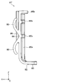
- the center bezel 7T is formed so that the normal direction of the back surface 71a of the flange portion 71 intersects the central axis CL. That is, the flange portion 71 of the center bezel 7T projects in a direction intersecting the radial direction.
- the tubular portion 72 has a shape in which one end side, that is, the tip end side in the axial direction of the cylinder is cut off diagonally by an inclined cutting surface.
- the flange portion 71 is provided on the inclined cut surface side of the tubular portion 72 in the axial direction.
- the sensor locking piece 74 extends in the axial direction, which is the direction intersecting the normal direction of the back surface 71a of the flange portion 71. Therefore, the pair of sensor locking pieces 74 arranged on both sides of the temporary assembly piece 76 in the axial circumferential direction have different lengths, that is, axial dimensions. On the other hand, as shown in FIG. 10B, the pair of sensor locking pieces 74 arranged on both sides of the projecting portion 75 in the axial direction are formed to have the same length.
- one of the pair of projecting portions 75 projects in the positive direction of the X-axis in the figure along the projecting direction of the flange portion 71.
- the other of the pair of projecting portions 75 projects in the negative direction of the X-axis in the drawing along the projecting direction of the flange portion 71.
- One of the pair of projecting portions 75 on the positive direction side of the X axis in the drawing is formed to have a longer axial dimension than the other.
- the center bezel 7T is also provided so that the retainer contact surface 75a is substantially parallel to the back surface 71a of the flange portion 71. Therefore, the retainer contact surface 75a in the center bezel 7T is formed so that the normal direction intersects the central axis CL.
- the distance between the retainer contact surface 75a and the back surface 71a of the flange portion 71 is set to be different between the corner bezel 7C and the center bezel 7T.
- the "misinstallation" in this case is an attempt to attach the center retainer 8T to the corner bezel 7C, or an attempt to attach the corner retainer 8C to the center bezel 7T.
- the center bezel 7T is formed so that the distance between the retainer contact surface 75a and the back surface 71a of the flange portion 71 is smaller than that of the corner bezel 7C. That is, the center bezel 7T is formed so that the width of the retainer insertion groove 75b, that is, the dimension in the Y-axis direction in the drawing is smaller than that of the corner bezel 7C.
- the bezel-side engaging portion 77a is the corner bezel 7C and the center bezel 7T relative to the angle defining recess 78 in the axial direction. It is provided so that the position is different.
- the "erroneous mounting” means that the corner sensor 1C is to be mounted in the third mounting hole V503 or the fourth mounting hole V504, or the center sensor 1T is mounted in the first mounting hole V501 or the first mounting hole V501 or the fourth mounting hole V504, referring to FIG. 1D. (Ii) It is intended to be mounted in the mounting hole V502.
- the bezel-side engaging portion 77a in the center bezel 7T has a shorter axial dimension than the temporary assembly piece 76 provided on the positive side of the Z-axis in FIG. 10A in the axial circumferential direction. It is provided at a position corresponding to the sensor locking piece 74 arranged between the protruding portion 75 on the negative direction side.
- the bezel-side engaging portion 77a in the center bezel 7T has the axial circumferential position in the assembled state on the Z-axis positive direction side of the two bezel locking projections 37 arranged on the connector portion 32 side of the central axis CL. It is provided so that it is in a position corresponding to the one. That is, as shown in FIG. 1D, the bezel-side engaging portion 77a in the center bezel 7T engages with the bumper-side engaging portion V52 provided in the third mounting hole V503 in the center sensor 1T. It is formed at a position where the mounting posture is the third posture. Further, the bezel-side engaging portion 77a is formed at a position where the mounting posture of the center sensor 1T becomes the fourth posture by engaging with the bumper-side engaging portion V52 provided in the fourth mounting hole V504. There is.
- the retainer 8 as the sensor fixture in the present disclosure attaches the ultrasonic sensor 1 to the temporarily assembled secondary assembly inserted through the mounting hole V5. It is configured to be fixed to the front bumper V3. Specifically, the retainer 8 is inserted between the projecting portion 75 and the front bumper V3 with the cylindrical portion 72 inserted through the mounting hole V5, so that the retainer 8 is inserted between the projecting portion 75 and the front bumper V3. It is designed to be sandwiched between.
- the retainer 8 is integrally formed of a hard synthetic resin.
- FIG. 11A to 11D show a schematic configuration of the corner retainer 8C.
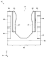
- 12A to 12D show a schematic configuration of the center retainer 8T.
- the rear view of the center retainer 8T shown in FIG. 12A corresponds to the rear view of the corner retainer 8C shown in FIG. 11A.
- the side view of the center retainer 8T shown in FIG. 12B corresponds to the side view of the corner retainer 8C shown in FIG. 11B.
- the plan view of the center retainer 8T shown in FIG. 12C corresponds to the plan view of the corner retainer 8C shown in FIG. 11C.
- the front view of the center retainer 8T shown in FIG. 12D corresponds to the front view of the corner retainer 8C shown in FIG. 11D.
- the corner retainer 8C and the center retainer 8T are formed in a substantially U shape in front view, which opens at the opening 81 in the positive direction of the Z axis.
- the retainer main body 82 constituting the main body portion of the corner retainer 8C and the center retainer 8T has a connecting portion 83 extending in the X-axis direction in the drawing and a Z-axis positive in the drawing from both ends of the connecting portion 83. It has a pair of extending portions 84 extending in the direction.
- the connecting portion 83 is provided so as to connect one ends of the pair of extending portions 84 to each other.
- the pair of extension portions 84 are provided so as to extend in a direction intersecting the central axis CL and face each other with the central axis CL in between.
- the connecting portion 83 and the pair of extending portions 84 form the above-mentioned substantially U-shape.
- the pair of extending portions 84 are provided so as to sandwich the tubular portion 72 while accommodating the tubular portion 72 in the bezel 7 in the inner space formed between them and opened by the opening 81. .. Further, the corner retainer 8C and the center retainer 8T are configured so that the arrangement direction of the pair of extending portions 84 sandwiching the central axis CL is orthogonal to the arrangement direction of the pair of small diameter portions 59 sandwiching the central axis CL. There is.
- the retainer main body 82 is formed in a substantially J shape in a side view by the connecting portion 83 and the pair of extending portions 84. That is, the connecting portion 83 is formed in a plate shape having a thickness direction in the Z-axis direction in the drawing.
- the extension portion 84 is formed in a plate shape having a thickness direction in the axial direction.
- the extension portion 84 is reinforced by a rib-shaped reinforcing portion 85 projecting in the axial direction.
- the reinforcing portion 85 has a first rib 85a and a second rib 85b.
- the first rib 85a extends in the width direction of the extension portion 84, that is, at an intermediate position in the X-axis direction in the drawing, in the Z-axis direction in the drawing, which is the extension direction of the extension portion 84.
- the second rib 85b extends outward from the first rib 85a in the width direction of the extending portion 84.
- the extension portion 84 has a bezel contact portion 86. As shown in FIGS. 11A and 12A, the bezel contact portion 86 is a portion inside the first rib 85a in the width direction of the extension portion 84, and is opened at the opening 81. It is projected toward the inner space.
- the bezel contact portion 86 has a bezel contact surface 87.
- the bezel contact surface 87 is a surface that comes into contact with the retainer contact surface 75a of the bezel 7 when the mounting state is formed, and is a smooth flat surface having a normal direction parallel to the central axis CL in the mounting state. It is formed.
- each of the pair of extending portions 84 is provided with a bezel engaging portion 88.
- the bezel engaging portion 88 is formed so as to be detachably engaged with the retainer engaging portion 79 shown in FIGS. 8D and 10C.
- the bezel engaging portion 88 has a shape as a convex portion that engages with the concave portion in the retainer engaging portion 79. That is, each of the pair of bezel engaging portions 88 is projected toward the space for accommodating the bezel 7 between the pair of extending portions 84.
- the corner retainer 8C and the center retainer 8T have a plurality of elastic portions 89.
- the elastic portion 89 is a cantilever-shaped leaf spring portion that protrudes from the retainer main body 82 on the positive direction side of the Y axis in the drawing, and is from a substantially central portion in the longitudinal direction of the extension portion 84 in the positive direction of the Y axis. It is extended in the direction of inclination.
- each of the pair of extending portions 84 is provided with a pair of elastic portions 89 in a gull-wing shape.
- the elastic portion 89 is configured to be elastically deformed while being in contact with the bumper back surface V32 in the mounted state.
- the distance between the retainer contact surface 75a and the back surface 71a in the flange portion 71 is set between the corner bezel 7C and the center bezel 7T. It is set to be different.
- the offset state of the bezel contact surface 87 that is, the distance from the reference surface is set to be different between the corner retainer 8C and the center retainer 8T.
- the "reference plane” is a virtual plane parallel to the XZ plane in the drawing, which approximates the position most distant from the extension portion 84 in all the elastic parts 89 in the natural state.
- the center bezel 7T is formed so that the distance between the retainer contact surface 75a and the back surface 71a of the flange portion 71 is smaller than that of the corner bezel 7C.
- the center retainer 8T is formed so that the distance of the bezel contact surface 87 from the reference surface is smaller than that of the corner retainer 8C.
- the ultrasonic sensor 1 can be attached to and detached from the front bumper V3 and the rear bumper V4 in a state where the front bumper V3 and the rear bumper V4 are usually removed from the vehicle body V1. Therefore, in the actual mounting method or mounting process, the Z-axis positive direction may be different from the upward direction.
- the sensor body 2A shown in FIGS. 3A and 3B is formed. Further, the anti-vibration spacer 6 shown in FIG. 6A and the like is attached to the corner bezel 7C and the center bezel 7T shown in FIGS. 8A and 10A.
- the ultrasonic microphone 4 and the cushion member 5 in the sensor body 2A are inserted into the corner bezel 7C to which the anti-vibration spacer 6 is mounted from the base end side in the axial direction of the tubular portion 72.
- the ultrasonic microphone 4 and the cushion member 5 in the sensor body 2A are inserted into the center bezel 7T to which the anti-vibration spacer 6 is mounted from the proximal end side in the axial direction of the tubular portion 72.
- the corner bezel 7C is attached to the sensor body 2A to form the secondary assembly shown in FIG. 7A. Further, by mounting the center bezel 7T on the sensor body 2A, the secondary assembly shown in FIG. 7B is formed.
- the cushion member 5 is housed in a tubular portion 72 of the bezel 7 while surrounding the ultrasonic microphone 4.
- the relative rotation angle or rotation posture of the corner bezel 7C and the center bezel 7T about the central axis CL with respect to the sensor main body 2A is defined by the engagement between the angle defining protrusion 38 and the angle defining recess 78.
- the axial position of the bezel-side engaging portion 77a is set to a predetermined position. That is, the bezel-side engaging portion 77a differs between the secondary assembly for the corner sensor 1C shown in FIG. 7A and the secondary assembly for the center sensor 1T shown in FIG. 7B in the axial circumferential direction. Placed in position.
- the bezel-side engaging portion 77a is the Z-axis of the two bezel locking projections 37 arranged on the connector portion 32 side of the central axis CL. It is the position corresponding to the one on the negative direction side.
- the bezel-side engaging portion 77a is on the Z-axis positive direction side of the two bezel locking projections 37 arranged on the connector portion 32 side with respect to the central axis CL. It will be the position corresponding to the one.
- the secondary assembly shown in FIG. 7A is inserted into the first mounting hole V501 from the bumper outer space SG side with the connector portion 32 at the head. Further, the secondary assembly shown in FIG. 7A is inserted into the second mounting hole V502 from the bumper outer space SG side with the connector portion 32 at the head. Similarly, the secondary assembly shown in FIG. 7B is inserted into the third mounting hole V503 from the bumper outer space SG side with the connector portion 32 at the head. Further, the secondary assembly shown in FIG. 7B is inserted into the fourth mounting hole V504 from the bumper outer space SG side with the connector portion 32 at the head.
- the bezel 7 is held by the front bumper V3 by the flange portion 71 and the flange facing surface 76c in the temporary assembly projection 76a, so that the secondary assembly is in the temporary assembly state.
- the retainer 8 is in a detachable posture on the SN side of the space inside the bumper.
- the attachment / detachment posture is a posture in which the opening 81 opens in the positive direction of the Z axis in the drawing and the elastic portion 89 faces the back surface V32 of the bumper.
- the opening 81 in the corner retainer 8C in the detachable posture is brought closer to the corner bezel 7C in the secondary assembly in the temporarily assembled state. Then, the corner retainer 8C is slid in the retainer mounting direction DS as shown in FIG. 1D.
- the opening 81 in the center retainer 8T in the detachable posture is brought closer to the center bezel 7T in the secondary assembly in the temporarily assembled state. Then, the center retainer 8T is slid in the retainer mounting direction DS as shown in FIG. 1D.
- each of the pair of extension portions 84 is placed in the retainer insertion groove 75b in the retainer mounting direction DS. Slide. Then, the corner retainer 8C and the center retainer 8T are pushed into the retainer mounting direction DS until the tubular portion 72 and the connecting portion 83 are in close contact with each other.
- the bezel contact surface 87 stably contacts the retainer contact surface 75a. Further, the retainer engaging portion 79 provided in the tubular portion 72 and the bezel engaging portion 88 provided in the extending portion 84 are engaged with each other. In this state, the retainer 8 is sandwiched between the projecting portion 75 on the bezel 7 and the bumper back surface V32 by the action of the elastic restoring force of the elastic portion 89.
- the retainer 8 is attached to the secondary assembly in the temporarily assembled state.
- the corner sensor 1C and the center sensor 1T are attached to the front bumper V3.
- the vehicle-mounted posture of the ultrasonic sensor 1 may be different depending on the mounting position in the vehicle width direction due to the convenience of wiring or the like.
- the corner sensor 1C has a front bumper V3 so that the connector extension direction DC faces the outside in the vehicle width direction, that is, the side opposite to the vehicle center surface PC. Can be attached to.
- the center sensor 1T is attached to the front bumper V3 so that the connector extension direction DC faces the inside in the vehicle width direction, that is, the vehicle center surface PC.
- the corner sensor 1C mounted in the first mounting hole V501 should direct the connector extension direction DC in the negative direction of the X axis in the drawing.
- the connector extension direction DC in the corner sensor 1C is directed in the positive direction of the X axis in the drawing, erroneous installation will occur.
- the ultrasonic sensor 1 may be formed into a different shape depending on the vehicle-mounted position.
- the corner sensor 1C and the center sensor 1T have different angles of intersection of the directional axis, that is, the central axis CL with respect to the front bumper V3 in the vehicle-mounted state.
- the corner bezel 7C and the center bezel 7T are formed in different shapes.
- the corner sensor 1C should be mounted in the first mounting hole V501.
- the directional shaft does not face a predetermined direction, resulting in erroneous mounting.
- the corner sensor 1C and the center sensor 1T have different shapes, it is possible to satisfactorily avoid erroneous mounting.
- the corner sensor 1C and the center sensor 1T have different shapes to the extent that the diameter or shape of the mounting hole V5 is different, the manufacturing cost will increase significantly.
- the outer diameter shape or the surface color of the flange portion 71 in the bezel 7 is different between the corner sensor 1C and the center sensor 1T, in addition to the increase in manufacturing cost, the entire design of the vehicle V may be adversely affected.
- the mounting hole V5 has a configuration in which one bumper-side engaging portion V52 is provided at a predetermined position in the circumferential direction.
- the bezel 7 has a configuration in which one bezel-side engaging portion 77a that engages with the bumper-side engaging portion V52 is provided at a predetermined position in the axial circumferential direction.
- the shape of the mounting hole V5 is common, and the circumferential position surrounding the center position CP of the bumper side engaging portion V52 is different to avoid erroneous mounting.
- the circumferential position of the bumper-side engaging portion V52 differs by 180 degrees between the first mounting hole V501 and the second mounting hole V502.
- the circumferential position of the bumper-side engaging portion V52 differs by 180 degrees between the third mounting hole V503 and the fourth mounting hole V504.
- the circumferential position of the bumper side engaging portion V52 differs by 90 degrees between the first mounting hole V501 and the third mounting hole V503.
- the circumferential position of the bumper-side engaging portion V52 differs by 90 degrees between the second mounting hole V502 and the fourth mounting hole V504.
- the corner bezel 7C and the center bezel 7T differ in the circumferential position of the bezel-side engaging portion 77a by 90 degrees.
- the connector extension direction DC is the direction along the Z axis in the drawing.
- the connector extension direction DC is the direction along the Z axis in the drawing.
- the bumper side engaging portion V52 is formed in a rounded shape. Therefore, even if the front bumper V3 is made of a metal plate material, it is possible to satisfactorily form the mounting hole V5 capable of avoiding erroneous mounting while avoiding an increase in manufacturing cost as much as possible.
- the bumper-side engaging portion V52 is formed as a bumper-side convex portion V53 projecting toward the inside of the mounting hole V5. That is, even if the bumper-side engaging portion V52 is provided, the hole diameter of the mounting hole V5 is not expanded as compared with the case where the bumper-side engaging portion V52 is not provided. Therefore, the expansion of the outer diameter of the flange portion 71 for covering the mounting hole V5 so that the mounting hole V5 is not exposed to the outside can be satisfactorily avoided. Therefore, the expansion of the bezel 7's physique can be satisfactorily avoided.
- the circumferential position of the bumper-side convex portion V53 as the bumper-side engaging portion V52 is indicated by an azimuth angle based on the direction from the center position CP toward the Z-axis positive direction in the figure. It is possible. When such an azimuth becomes a multiple of 90 degrees as shown by the alternate long and short dash line in the figure, when the secondary assembly is inserted into the mounting hole V5 from the bumper outer space SG side with the connector portion 32 at the head. The bumper-side convex portion V53 interferes with various parts in the secondary assembly.
- the bumper-side convex portions V53 interfere with both ends of the box-shaped portion 31 in the sensor case 3 in the width direction. Further, for example, when the azimuth becomes 90 degrees or 270 degrees, the bumper side convex portion V53 interferes with the portion of the protruding portion 75 of the bezel 7 where the retainer engaging portion 79 is provided.
- the azimuth angle corresponding to the circumferential position of the bumper-side convex portion V53 as the bumper-side engaging portion V52 is set so as not to be a multiple of 90 degrees.
- the mounting hole V5 has a configuration in which one bumper-side engaging portion V52 is provided at an azimuth angle of 45 degrees, 135 degrees, 225 degrees, or 315 degrees. Therefore, it is possible to avoid erroneous installation as much as possible with the minimum processing.
- the first mounting hole V501 is provided with bumper-side convex portions V53 as bumper-side engaging portions V52 at two locations having azimuth angles of 225 degrees and 315 degrees. Be done.
- the second mounting hole V502 is provided with bumper-side convex portions V53 as bumper-side engaging portions V52 at two locations having azimuth angles of 45 degrees and 135 degrees.
- the corner bezel 7C is also provided with two bezel-side engaging portions 77a.
- the third mounting hole V503 and the fourth mounting hole V504 are each provided with only one bumper-side convex portion V53 as the bumper-side engaging portion V52, as in the present embodiment.
- the center bezel 7T is also provided with only one bezel-side engaging portion 77a.
- an error in the mounting angle when mounting the corner sensor 1C in the first mounting hole V501 and the second mounting hole V502 can be satisfactorily avoided as in the present embodiment. Further, an error in the mounting angle when mounting the center sensor 1T in the third mounting hole V503 and the fourth mounting hole V504 can be satisfactorily avoided.
- the center sensor 1T provided with the center bezel 7T having only one bezel-side engaging portion 77a cannot be mounted on the first mounting hole V501 and the second mounting hole V502 provided with two bumper-side convex portions V53. Is. However, the corner sensor 1C provided with the corner bezel 7C provided with two bezel-side engaging portions 77a is provided in the third mounting hole V503 and the fourth mounting hole V504 provided with only one bumper-side convex portion V53. It can be installed. Therefore, in such another configuration, erroneous mounting between the corner sensor 1C and the center sensor 1T cannot be completely avoided.
- the distance between the retainer contact surface 75a and the back surface 71a of the flange portion 71 is different between the corner bezel 7C and the center bezel 7T.
- the offset state of the bezel contact surface 87 differs between the corner retainer 8C and the center retainer 8T.
- the shape change other than the shape change due to the inclination of the flange portion 71 with respect to the central axis CL is minimized in the corner bezel 7C and the center bezel 7T.
- the corner bezel 7C and the center bezel 7T minimize the change in the outer shape of the flange portion 71.
- the retainer mounting direction DS is defined in a predetermined direction by a pair of projecting portions 75 provided on the corner bezel 7C and the center bezel 7T.
- the common sensor body 2A is used for the corner sensor 1C and the center sensor 1T. That is, the corner sensor 1C is formed by attaching the corner bezel 7C to one type of sensor body 2A, and the center sensor 1T is formed by attaching the center bezel 7T. This makes it possible to realize variations in the directivity direction with a minimum of changing the shape of parts.
- the vehicle-mounted structure S may be configured such that the third posture has the same vehicle-mounted angle as the first posture and the fourth posture has the same vehicle-mounted angle as the second posture. That is, for example, referring to FIG. 1D, each of ⁇ 1 and ⁇ 2 may be rotated 180 degrees around the center position CP. Alternatively, each of ⁇ 3 and ⁇ 4 may be rotated 180 degrees around the center position CP.
- the mounting angle of the corner sensor 1C mounted on the first mounting hole V501 becomes the same as the mounting angle of the center sensor 1T mounted on the third mounting hole V503.
- the mounting angle of the corner sensor 1C mounted on the second mounting hole V502 is the same as the mounting angle of the center sensor 1T mounted on the fourth mounting hole V504.
- the connector extension direction DC in all the corner sensors 1C and the center sensor 1T attached to the front bumper V3 faces the inside in the vehicle width direction, that is, the vehicle center surface PC.
- the connector extension direction DC in all the corner sensors 1C and the center sensor 1T attached to the front bumper V3 faces the outside in the vehicle width direction, that is, the side opposite to the vehicle center surface PC.
- the hole diameters of the first mounting hole V501 and the second mounting hole V502 are the same, and the hole diameters of the third mounting hole V503 and the fourth mounting hole V504 are the same, the first mounting hole V501 and the third mounting hole V503
- the ultrasonic sensor 1 attached to the front bumper V3 has been described.
- the present disclosure is not limited to such embodiments. That is, the configuration of the ultrasonic sensor 1 attached to the rear bumper V4 can also be easily understood from the description of the above embodiment.
- the mounting target of the ultrasonic sensor 1 is not limited to the front bumper V3 and the rear bumper V4.
- the ultrasonic sensor 1 can be attached to the vehicle body panel V2. That is, the mounting hole V5 may also be provided on the vehicle body panel V2.
- the ultrasonic sensor 1 is not limited to a configuration capable of transmitting and receiving ultrasonic waves. That is, for example, the ultrasonic sensor 1 may have a configuration capable of only transmitting ultrasonic waves. Alternatively, the ultrasonic sensor 1 may have only a function of receiving a reflected wave of an exploration wave, which is an ultrasonic wave transmitted from another ultrasonic transmitter, by an object existing in the surroundings.
- each part of the ultrasonic sensor 1 is not limited to the above specific example. Specifically, for example, the material constituting each part can be appropriately changed from the above specific example. Further, the plurality of components formed of the same material may be formed of different materials. Similarly, multiple components that were made of different materials may be made of the same material.
- the plurality of components that are seamlessly and integrally formed with each other may be formed by laminating separate members from each other.
- a plurality of components formed by laminating separate members may be seamlessly and integrally formed with each other.
- the specific configuration of the sensor case 3 is not limited to the above specific example. That is, for example, the structure and extension direction of the connector portion 32 can be changed as appropriate. Further, the shape of the microphone support portion 33 is not limited to a substantially cylindrical shape, and may be a substantially elliptical cylinder shape, a substantially long cylindrical shape, a substantially polygonal cylinder shape, or the like.
- the configuration of the sensor case 3 for the corner sensor 1C and the sensor case 3 for the center sensor 1T may be different. Further, the angle formed by the connector extending direction DC in the corner sensor 1C and the X-axis in the drawing and the angle formed by the connector extending direction DC in the center sensor 1T and the X-axis in the drawing may be substantially the same. And may be different.
- the sensor case 3 for the corner sensor 1C and the sensor case 3 for the center sensor 1T have the same configuration. That is, the angle formed by the connector extension direction DC and the central axis CL is the same in the sensor case 3 for the corner sensor 1C and the sensor case 3 for the center sensor 1T. Therefore, in the center sensor 1T, the angle formed by the connector extension direction DC and the X-axis in the drawing is larger than that of the corner sensor 1C by the inclination angle of the central axis CL with respect to the normal of the XZ plane in the drawing.
- the angle formed by the connector extension direction DC and the center axis CL may be different between the sensor case 3 for the corner sensor 1C and the sensor case 3 for the center sensor 1T.
- the angle formed by the connector extension direction DC in the corner sensor 1C and the X-axis in the figure can be made substantially the same as the angle formed by the connector extension direction DC in the center sensor 1T and the X-axis in the figure. can. That is, the sensor case 3 for the corner sensor 1C and the sensor case 3 for the center sensor 1T are configured so that the angle formed by the virtual plane parallel to the back surface 71a of the flange portion 71 and the connector extending direction DC is constant. obtain.
- the outer shape of the ultrasonic microphone 4, that is, the microphone case 42 is not limited to a substantially cylindrical shape, and may be a substantially elliptical columnar shape, a substantially regular polygonal columnar shape, or the like.
- the electric-mechanical conversion element constituting the ultrasonic element 41 is not limited to the piezoelectric element.
- the specific configuration of the cushion member 5 is not limited to the above specific example. That is, for example, the shape of the cushion member 5 is not limited to a substantially cylindrical shape, and may be a substantially elliptical cylinder shape, a substantially long cylindrical shape, a substantially polygonal cylinder shape, or the like.
- the cushion member 5 may be assembled to the sensor body 2A, which is the primary assembly, to form the secondary assembly.
- the ultrasonic microphone 4 is supported by the microphone support portion 33 in the sensor case 3 without the intervention of the cushion member 5.
- the cushion member 5 is formed in a tubular shape having substantially the same axial dimension as the axial dimension of the ultrasonic microphone 4, that is, the microphone case 42.
- the specific configurations of the bezel 7 and the retainer 8, which are parts for attaching the ultrasonic sensor 1 to a plate-shaped vehicle body part (for example, front bumper V3), are not limited to the above specific examples. Specifically, for example, the detailed configuration of the bezel 7 and / or the retainer 8 can be appropriately changed from the above specific example.
- the hole diameters of the first mounting hole V501 and the third mounting hole V503 may be different.
- the corner bezel 7C and the center bezel 7T have different outer diameters.
- the uneven relationship between the bezel-side engaging portion 77a and the bumper-side engaging portion V52 can be set in reverse. That is, the bezel-side engaging portion 77a can be provided as a convex portion in which the radial protrusion amount of the tip-side projecting portion 77 is larger than that of other portions. In this case, the bumper-side engaging portion V52 may be provided as a recess in which the hole diameter of the mounting hole V5 is expanded.
- the bumper side engaging portion V52 is provided as a recess in which the hole diameter of the mounting hole V5 is expanded, the both ends of the recess in the circumferential direction are relative to each other.
- a convex portion is formed on the surface. That is, the formation of the convex portion inevitably causes a concave portion, and the formation of the concave portion inevitably causes a convex portion. Therefore, the difference in whether the bumper-side engaging portion V52 is a convex portion or a concave portion is only relative, and unless the applicant expressly limits it in the course of filing, the technique of the present disclosure is made thereby. The judgment of the affiliation of the allegedly infringing property with respect to the target range is not affected. The same applies to the difference in whether the bezel-side engaging portion 77a is a convex portion or a concave portion.
- the modified example is not limited to the above example. That is, for example, other than those exemplified above, a plurality of embodiments can be combined with each other as long as there is no technical contradiction. Similarly, multiple variants can be combined with each other as long as they are not technically inconsistent.
Landscapes
- Engineering & Computer Science (AREA)
- Radar, Positioning & Navigation (AREA)
- Remote Sensing (AREA)
- Physics & Mathematics (AREA)
- Mechanical Engineering (AREA)
- Computer Networks & Wireless Communication (AREA)
- General Physics & Mathematics (AREA)
- Acoustics & Sound (AREA)
- Measurement Of Velocity Or Position Using Acoustic Or Ultrasonic Waves (AREA)
Abstract
Une structure embarquée (S) est divulguée, dans laquelle un dispositif embarqué (1C, 1T) est monté sur une partie de carrosserie de véhicule (V3) qui est en forme de plaque et qui a un trou traversant (V501-V504). Le dispositif embarqué comprend une partie tubulaire (7) qui est passée à travers le trou traversant et un élément de fixation (8) qui fixe la partie tubulaire à la partie de carrosserie de véhicule. La partie tubulaire a une carrosserie principale tubulaire qui s'étend le long d'un axe central et une partie en saillie qui fait saillie à partir de la carrosserie principale dans une direction qui coupe l'axe central. L'élément de fixation est maintenu entre la partie en saillie et la partie de carrosserie de véhicule. Le trou traversant présente, à une position prescrite dans la direction circonférentielle entourant une position centrale (CP), une partie de mise en prise côté carrosserie de véhicule (V52) qui vient en prise avec une partie de mise en prise côté dispositif qui est une partie en relief disposée sur la partie tubulaire.
Priority Applications (3)
| Application Number | Priority Date | Filing Date | Title |
|---|---|---|---|
| DE112021002622.4T DE112021002622T5 (de) | 2020-04-28 | 2021-03-23 | Am Fahrzeug montierte Baugruppe Verweis auf verwandtes Dokument |
| CN202180031562.0A CN115461249A (zh) | 2020-04-28 | 2021-03-23 | 车载构造 |
| US18/049,829 US20230070901A1 (en) | 2020-04-28 | 2022-10-26 | Vehicle-mounted assembly |
Applications Claiming Priority (2)
| Application Number | Priority Date | Filing Date | Title |
|---|---|---|---|
| JP2020079506A JP7243674B2 (ja) | 2020-04-28 | 2020-04-28 | 車載構造 |
| JP2020-079506 | 2020-04-28 |
Related Child Applications (1)
| Application Number | Title | Priority Date | Filing Date |
|---|---|---|---|
| US18/049,829 Continuation US20230070901A1 (en) | 2020-04-28 | 2022-10-26 | Vehicle-mounted assembly |
Publications (1)
| Publication Number | Publication Date |
|---|---|
| WO2021220670A1 true WO2021220670A1 (fr) | 2021-11-04 |
Family
ID=78279084
Family Applications (1)
| Application Number | Title | Priority Date | Filing Date |
|---|---|---|---|
| PCT/JP2021/011964 WO2021220670A1 (fr) | 2020-04-28 | 2021-03-23 | Structure embarquée |
Country Status (5)
| Country | Link |
|---|---|
| US (1) | US20230070901A1 (fr) |
| JP (1) | JP7243674B2 (fr) |
| CN (1) | CN115461249A (fr) |
| DE (1) | DE112021002622T5 (fr) |
| WO (1) | WO2021220670A1 (fr) |
Citations (3)
| Publication number | Priority date | Publication date | Assignee | Title |
|---|---|---|---|---|
| JP2008026231A (ja) * | 2006-07-24 | 2008-02-07 | Matsushita Electric Works Ltd | センサの支持構造 |
| JP2010025813A (ja) * | 2008-07-22 | 2010-02-04 | Panasonic Electric Works Co Ltd | センサの支持構造 |
| JP2018146564A (ja) * | 2017-03-07 | 2018-09-20 | 株式会社デンソー | 超音波センサ |
Family Cites Families (6)
| Publication number | Priority date | Publication date | Assignee | Title |
|---|---|---|---|---|
| JP3628480B2 (ja) | 1997-05-30 | 2005-03-09 | 株式会社デンソー | 超音波センサ |
| JP6274852B2 (ja) * | 2013-12-17 | 2018-02-07 | カルソニックカンセイ株式会社 | 車載用機器の取付構造 |
| JP6520730B2 (ja) * | 2016-01-20 | 2019-05-29 | 株式会社豊田自動織機 | 車両用フロントグリル |
| CN106772330B (zh) * | 2016-12-30 | 2023-08-22 | 铁将军汽车电子股份有限公司 | 探头装置及汽车 |
| CN208530500U (zh) * | 2018-06-29 | 2019-02-22 | 比亚迪股份有限公司 | 车辆的雷达安装装置以及车辆 |
| JP7176934B2 (ja) | 2018-11-13 | 2022-11-22 | 文化シヤッター株式会社 | 止水装置 |
-
2020
- 2020-04-28 JP JP2020079506A patent/JP7243674B2/ja active Active
-
2021
- 2021-03-23 CN CN202180031562.0A patent/CN115461249A/zh active Pending
- 2021-03-23 WO PCT/JP2021/011964 patent/WO2021220670A1/fr active Application Filing
- 2021-03-23 DE DE112021002622.4T patent/DE112021002622T5/de active Pending
-
2022
- 2022-10-26 US US18/049,829 patent/US20230070901A1/en active Pending
Patent Citations (3)
| Publication number | Priority date | Publication date | Assignee | Title |
|---|---|---|---|---|
| JP2008026231A (ja) * | 2006-07-24 | 2008-02-07 | Matsushita Electric Works Ltd | センサの支持構造 |
| JP2010025813A (ja) * | 2008-07-22 | 2010-02-04 | Panasonic Electric Works Co Ltd | センサの支持構造 |
| JP2018146564A (ja) * | 2017-03-07 | 2018-09-20 | 株式会社デンソー | 超音波センサ |
Also Published As
| Publication number | Publication date |
|---|---|
| JP2021172281A (ja) | 2021-11-01 |
| US20230070901A1 (en) | 2023-03-09 |
| DE112021002622T5 (de) | 2023-04-06 |
| JP7243674B2 (ja) | 2023-03-22 |
| CN115461249A (zh) | 2022-12-09 |
Similar Documents
| Publication | Publication Date | Title |
|---|---|---|
| US7313960B2 (en) | Ultrasonic sensor assembly | |
| EP2808694B2 (fr) | Dispositif à onde ultrasonore | |
| CN103502840B (zh) | 超声波传感器 | |
| US20070115758A1 (en) | Obstacle detection device | |
| WO2017149931A1 (fr) | Capteur à ultrasons et dispositif de capteur à ultrasons le comprenant | |
| JP5849848B2 (ja) | 車両用超音波センサ装置及び車両用超音波センサ装置の組み付け方法 | |
| WO2021220670A1 (fr) | Structure embarquée | |
| JP5984081B2 (ja) | 超音波センサ | |
| JP4791290B2 (ja) | コネクタ接続構造 | |
| WO2021215177A1 (fr) | Capteur ultrasonore et absorbeur de vibration | |
| US11307305B2 (en) | Ultrasonic sensor | |
| WO2021205846A1 (fr) | Capteur à ultrasons et outil de fixation de capteur | |
| JP7167567B2 (ja) | 超音波センサ | |
| US20220043147A1 (en) | Ultrasonic sensor | |
| WO2021187243A1 (fr) | Transducteur ultrasonique, capteur ultrasonique, dispositif de détection d'objets, procédé de détection d'objets et programme de détection d'objets | |
| JP7413921B2 (ja) | 超音波センサ取付構造 | |
| WO2021172094A1 (fr) | Transducteur ultrasonore | |
| JP7435282B2 (ja) | 超音波トランスデューサ |
Legal Events
| Date | Code | Title | Description |
|---|---|---|---|
| 121 | Ep: the epo has been informed by wipo that ep was designated in this application |
Ref document number: 21797623 Country of ref document: EP Kind code of ref document: A1 |
|
| 122 | Ep: pct application non-entry in european phase |
Ref document number: 21797623 Country of ref document: EP Kind code of ref document: A1 |