WO2021220670A1 - On-vehicle structure - Google Patents
On-vehicle structure Download PDFInfo
- Publication number
- WO2021220670A1 WO2021220670A1 PCT/JP2021/011964 JP2021011964W WO2021220670A1 WO 2021220670 A1 WO2021220670 A1 WO 2021220670A1 JP 2021011964 W JP2021011964 W JP 2021011964W WO 2021220670 A1 WO2021220670 A1 WO 2021220670A1
- Authority
- WO
- WIPO (PCT)
- Prior art keywords
- vehicle
- hole
- posture
- bezel
- engaging portion
- Prior art date
Links
Images


Classifications
-
- B—PERFORMING OPERATIONS; TRANSPORTING
- B60—VEHICLES IN GENERAL
- B60R—VEHICLES, VEHICLE FITTINGS, OR VEHICLE PARTS, NOT OTHERWISE PROVIDED FOR
- B60R19/00—Wheel guards; Radiator guards, e.g. grilles; Obstruction removers; Fittings damping bouncing force in collisions
- B60R19/02—Bumpers, i.e. impact receiving or absorbing members for protecting vehicles or fending off blows from other vehicles or objects
- B60R19/48—Bumpers, i.e. impact receiving or absorbing members for protecting vehicles or fending off blows from other vehicles or objects combined with, or convertible into, other devices or objects, e.g. bumpers combined with road brushes, bumpers convertible into beds
- B60R19/483—Bumpers, i.e. impact receiving or absorbing members for protecting vehicles or fending off blows from other vehicles or objects combined with, or convertible into, other devices or objects, e.g. bumpers combined with road brushes, bumpers convertible into beds with obstacle sensors of electric or electronic type
-
- G—PHYSICS
- G01—MEASURING; TESTING
- G01S—RADIO DIRECTION-FINDING; RADIO NAVIGATION; DETERMINING DISTANCE OR VELOCITY BY USE OF RADIO WAVES; LOCATING OR PRESENCE-DETECTING BY USE OF THE REFLECTION OR RERADIATION OF RADIO WAVES; ANALOGOUS ARRANGEMENTS USING OTHER WAVES
- G01S15/00—Systems using the reflection or reradiation of acoustic waves, e.g. sonar systems
- G01S15/88—Sonar systems specially adapted for specific applications
- G01S15/93—Sonar systems specially adapted for specific applications for anti-collision purposes
- G01S15/931—Sonar systems specially adapted for specific applications for anti-collision purposes of land vehicles
-
- G—PHYSICS
- G01—MEASURING; TESTING
- G01S—RADIO DIRECTION-FINDING; RADIO NAVIGATION; DETERMINING DISTANCE OR VELOCITY BY USE OF RADIO WAVES; LOCATING OR PRESENCE-DETECTING BY USE OF THE REFLECTION OR RERADIATION OF RADIO WAVES; ANALOGOUS ARRANGEMENTS USING OTHER WAVES
- G01S7/00—Details of systems according to groups G01S13/00, G01S15/00, G01S17/00
- G01S7/52—Details of systems according to groups G01S13/00, G01S15/00, G01S17/00 of systems according to group G01S15/00
- G01S7/521—Constructional features
Definitions
- the present disclosure relates to an in-vehicle structure in which an in-vehicle device is attached to a plate-shaped vehicle body component having a through hole.
- an obstacle detection device for a vehicle that is attached to a bumper of a vehicle to detect an obstacle at the rear or corner of the vehicle.
- an ultrasonic sensor is attached to the bumper of the vehicle, and the obstacle is detected by receiving the ultrasonic wave reflected by the obstacle.
- the directivity of the ultrasonic sensor may be narrowed in the vertical direction and widened in the horizontal direction in order to not detect the ground as an obstacle and to increase the detection area in the horizontal direction. be.
- the bumper is provided with an oval mounting hole.
- the case of the ultrasonic sensor is formed with flat surfaces having flat surfaces on both side surfaces. According to such a configuration, by inserting the case of the ultrasonic sensor into the mounting hole formed in the bumper, the ultrasonic sensor can be mounted on the bumper of the vehicle without confusing the top, bottom, left and right of the case. Therefore, when detecting an obstacle, the directivity of the ultrasonic sensor can be widened in the horizontal direction and narrowed in the vertical direction.
- erroneous attachment When an in-vehicle device such as an ultrasonic sensor is attached to a vehicle body part such as a bumper, erroneous attachment may occur.
- the "erroneous mounting” includes, for example, as described in Patent Document 1, trying to mount the vehicle body parts in a mounting posture different from the original one.
- "wrong mounting” includes, for example, attempting to mount an in-vehicle device having an incorrect part number or configuration different from the one to be originally mounted on a vehicle body component.
- the present disclosure provides, for example, an in-vehicle structure capable of further better suppressing the occurrence of erroneous attachment of an in-vehicle device to a vehicle body component to be attached.
- the in-vehicle structure has a structure in which an in-vehicle device is attached to a plate-shaped body part having a through hole.
- the in-vehicle device has a cylindrical main body extending along the central axis and a protruding portion protruding from the main body in a direction intersecting the central axis, and is inserted into the through hole. It has a shaped part and a fixture for fixing the cylindrical part to the car body part by being sandwiched between the projecting portion and the car body part.
- the through hole has a vehicle body-side engaging portion that engages with a device-side engaging portion, which is an uneven portion provided on the tubular component, at a predetermined position in the circumferential direction surrounding the central position.
- each element may have a reference code in parentheses.
- the reference numeral indicates only an example of the correspondence between the same element and the specific configuration described in the embodiment described later. Therefore, the present disclosure is not limited to the description of the reference code.
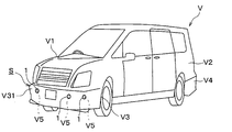
- FIG. 1C It is a perspective view which shows the appearance of the vehicle which has the vehicle-mounted structure which concerns on embodiment. It is a rear view which enlarges and shows the circumference of the mounting hole in the front bumper shown in FIG. 1A. It is a back view which shows the outline of the vehicle-mounted structure shown in FIG. 1A schematically. It is a rear view which shows the vehicle-mounted structure shown in FIG. 1C in an exploded manner. It is a top view of the corner sensor shown in FIG. 1C. It is a rear view of the corner sensor shown in FIG. 1C. It is a right side view of the corner sensor shown in FIG. 1C. It is a left side view of the corner sensor shown in FIG. 1C. It is a top view of the center sensor shown in FIG.
- FIG. 1C It is a top view which shows the schematic structure of the sensor main body shown in FIG. 1C and FIG. 1D. It is a left side view which shows the schematic structure of the sensor body shown in FIG. 1C and FIG. 1D. It is a partial cross-sectional view which shows the schematic structure of the sensor body shown in FIG. 1C and FIG. 1D. It is a front view which shows the schematic structure of the microphone case shown in FIG. It is an enlarged plan view which shows the anti-vibration spacer shown in FIG. 2A and FIG. 2E. It is a front view of the anti-vibration spacer shown in FIG. 6A.
- FIG. 7 is an enlarged plan view showing the corner bezel shown in FIG. 7A. It is a front view of the corner bezel shown in FIG. 8A. It is a right side view of the corner bezel shown in FIG. 8A. It is a rear view of the corner bezel shown in FIG. 8A. It is a cross-sectional view which shows the part of the bezel shown in FIG.
- FIG. 7B is an enlarged plan view showing the center bezel shown in FIG. 7B. It is a front view of the center bezel shown in FIG. 10A. It is a perspective view which looked at the center bezel shown in FIG. 10A from the back side. It is a rear view of the corner retainer shown in FIGS. 2A-2D. It is a right side view of the corner retainer shown in FIG. 11A. It is a top view of the corner retainer shown in FIG. 11A. It is a front view of the corner retainer shown in FIG. 11A. It is a rear view of the center retainer shown in FIG. 2E. It is a right side view of the center retainer shown in FIG. 12A. It is a top view of the center retainer shown in FIG. 12A. It is a front view of the center retainer shown in FIG. 12A.
- the ultrasonic sensor 1 as an in-vehicle device has a configuration as an in-vehicle clearance sonar. That is, the ultrasonic sensor 1 is configured to be mounted on the vehicle V so that it can detect an obstacle that is an object existing around the vehicle V.
- the ultrasonic sensor 1 has a transmission / reception integrated configuration capable of transmitting and receiving ultrasonic waves. That is, the ultrasonic sensor 1 transmits an ultrasonic exploration wave toward the external space of the vehicle V, receives a received wave including a reflected wave due to an obstacle of the exploration wave, and receives a reception result of the received wave. It is configured to generate and output a detection signal according to the above.
- the ultrasonic sensor 1 has a configuration having different directivity characteristics in the horizontal direction and the vertical vertical direction. That is, the ultrasonic sensor 1 is configured to radiate an exploration wave with a wide horizontal direction and a narrow vertical vertical direction.
- the "direction angle” refers to the generatrix and the directional axis in the elliptical cone when the range of -6 dB from the central sound pressure, which is the sound pressure on the directional axis, is represented by a substantially elliptical cone shape centered on the directional axis. It is the angle between the two, and is also called the "half-value angle".
- the “directional axis” is a virtual straight line extending from the ultrasonic sensor 1 toward the direction in which the exploration wave has the maximum sound pressure, and may also be referred to as a directional central axis or a detection axis.
- Vehicle V is a so-called four-wheeled vehicle, and has a box-shaped body V1.
- the vehicle body V1 has a vehicle body panel V2, a front bumper V3, and a rear bumper V4, which are plate-shaped vehicle body parts constituting the outer plate.
- the front bumper V3 is provided at the front end of the vehicle body V1.
- the rear bumper V4 is provided at the rear end of the vehicle body V1.
- the vehicle body panel V2, the front bumper V3, and the rear bumper V4 are formed of a metal plate material.
- the ultrasonic sensor 1 is configured to be attached to the front bumper V3 to detect objects existing in front of and to the front of the vehicle V. Similarly, the ultrasonic sensor 1 is configured to be attached to the rear bumper V4 to detect an object existing behind and to the rear side of the vehicle V.
- the state in which the ultrasonic sensor 1 is attached to the front bumper V3 or the rear bumper V4 is hereinafter referred to as "attached state”. Further, a state in which the ultrasonic sensor 1 is mounted on the vehicle V by being attached to the front bumper V3 or the rear bumper V4 provided on the vehicle body V1 is hereinafter referred to as an "vehicle-mounted state”.
- the “vehicle-mounted state” includes the “mounted state”. That is, the ultrasonic sensor 1 in the vehicle-mounted state also corresponds to the “mounted state”.
- the vehicle-mounted structure S according to the present embodiment is a structure in which an ultrasonic sensor 1 is attached to a front bumper V3 or a rear bumper V4, which are plate-shaped vehicle body parts.
- a plurality of (for example, four) ultrasonic sensors 1 are attached to the front bumper V3 in the vehicle-mounted state.
- the plurality of ultrasonic sensors 1 attached to the front bumper V3 are arranged at different positions in the vehicle width direction.
- a plurality of (for example, four) ultrasonic sensors 1 are attached to the rear bumper V4.
- the front bumper V3 and the rear bumper V4 are formed with mounting holes V5, which are through holes for mounting the ultrasonic sensor 1.
- the vehicle-mounted structure S formed by attaching the ultrasonic sensor 1 to the rear bumper V4 also has the same configuration as that of the present embodiment described below.
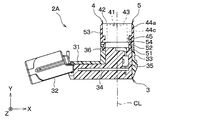
- the mounting hole V5 is provided so as to open toward the external space of the vehicle V at the bumper outer surface V31 by penetrating the front bumper V3 in the thickness direction thereof.
- the bumper outer surface V31 is the outer surface of the front bumper V3 and is provided so as to face the external space of the vehicle V in the vehicle-mounted state.
- FIG. 1B is an enlarged view of the mounting hole V5 as viewed from the bumper back surface V32 side, which is the back surface of the bumper outer surface V31.
- the mounting hole V5 is formed in the shape of a round hole having a columnar space inside. That is, the mounting hole V5 has an inner edge V51 having a cylindrical inner surface shape.
- the mounting hole V5 has a bumper-side engaging portion V52 as a vehicle body-side engaging portion in order to prevent erroneous mounting of the ultrasonic sensor 1.
- “Misinstallation” includes installing or attempting to install an ultrasonic sensor 1 having an incorrect part number or configuration that is different from the one that should be originally installed in the installation hole V5 in a specific vehicle V.
- one mounting hole V5 is provided with one bumper-side engaging portion V52.
- the bumper side engaging portion V52 is provided at a predetermined position in the circumferential direction surrounding the center position CP of the mounting hole V5.
- the center position CP is the position of the center point of the arc in the mounting hole V5 in the arc-shaped portion in the front view or the rear view other than the bumper side engaging portion V52.
- the center position CP is the center position of the arc forming the line of intersection between the inner edge V51 of the cylindrical inner surface in the mounting hole V5 and the outer surface V31 of the bumper or the back surface V32 of the bumper.
- the "circumferential direction" in the mounting hole V5 is the circumferential direction when it is assumed that the substantially circular mounting hole V5 is a perfect circle without the bumper side engaging portion V52.
- the position in the circumferential direction is hereinafter simply referred to as "circumferential position". The details of the "predetermined position" where the bumper-side engaging portion V52 is provided will be described later.
- "wrong mounting” includes mounting or attempting to mount an ultrasonic sensor 1 having the correct part number or configuration in a mounting posture different from the original one.
- the mounting posture is a posture relative to the front bumper V3 of the ultrasonic sensor 1 in the mounted state, and includes a mounting angle.
- the mounting angle is a rotational posture centered on the directional axis of the ultrasonic sensor 1 in the mounted state.
- the mounting posture in the vehicle-mounted state is also referred to as "vehicle-mounted posture”.
- the mounting angle in the vehicle-mounted state is the mounting angle around the directional axis of the ultrasonic sensor 1, and is also referred to as the “vehicle-mounted angle”.
- the bumper-side engaging portion V52 is provided so as to define a mounting angle, that is, an in-vehicle angle by engaging with a device-side engaging portion described later provided in the ultrasonic sensor 1.
- the bumper side engaging portion V52 is formed as a concavo-convex portion in which the hole diameter of the mounting hole V5, which is a through hole formed in a substantially circular shape, changes.
- the hole diameter of the mounting hole V5 is the distance from the center position CP of the mounting hole V5 to the inner edge V51. That is, the mounting hole V5 has a shape in which the bumper-side engaging portion V52, which is an uneven portion, is provided on the inner edge V51 of the round hole.
- the bumper-side engaging portion V52 has a bumper-side convex portion V53 and a pair of bumper-side concave portions V54.
- the bumper-side convex portion V53 is a convex portion projecting toward the inside of the mounting hole V5, and the tip portion in the projecting direction is formed in a rounded shape in the front view. Specifically, the bumper-side convex portion V53 is projected toward the center position CP at the inner edge V51 of the mounting hole V5.
- the bumper-side concave portion V54 is a portion formed in a relatively concave shape at both ends of the bumper-side convex portion V53 in the circumferential direction by providing the bumper-side convex portion V53, and has a rounded shape when viewed from the front. Is formed in. That is, the mounting hole V5 has a shape in which the diameter is reduced by the bumper-side convex portion V53 and the radius is constant at other portions.
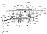
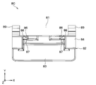
- FIGS. 1C and 1D are schematic views showing the vehicle-mounted structure S according to the present embodiment as viewed from the back surface V32 side of the bumper.
- the schematic configuration of the vehicle-mounted structure S according to the present embodiment will be described with reference to FIGS. 1C and 1D.
- the Cartesian coordinate system is set with reference to the gravitational action direction in the vehicle-mounted state.
- the present disclosure is not limited to specific examples of such Cartesian coordinate systems.
- the upward direction along the vertical upper direction is defined as the Z-axis positive direction.
- the vertical upper direction is a direction opposite to the gravitational action direction when the vehicle V is stably placed on a horizontal plane in a state where it can travel.
- the upward direction is the same direction as the vertically upper direction or the direction forming a predetermined small acute angle ⁇ with the vertically upper direction. ⁇ is, for example, 10 degrees or less. Therefore, depending on the shape of the front bumper V3 and the like, the Z-axis positive direction may be the same direction as the vertically upward direction, or may be a direction intersecting the vertically upward direction. Looking at a specific part of the vehicle V from the vertically upper side to the vertically lower part while the vehicle V is stably placed on a horizontal plane in a state where the vehicle V can travel is hereinafter referred to as "plan view". That is.
- FIGS. 1C and 1D parts of the front bumper V3 extending in the vehicle width direction other than the part to which the ultrasonic sensor 1 is attached are omitted. Further, for the convenience of illustration, the portion of the front bumper V3 to which the ultrasonic sensor 1 is attached is also shown so that the directional axis is orthogonal to the paper surface. Therefore, the X-axis direction in the figure is a horizontal direction along the vehicle width direction.
- the vehicle width direction is a direction orthogonal to the vehicle overall length direction and the vehicle height direction.
- the vehicle height direction is a direction parallel to the gravitational action direction when the vehicle V is stably placed on a horizontal plane in a state where it can travel.
- the vehicle total length direction is a direction that defines the total length of the vehicle V, and specifically, is a direction parallel to the direction in which the front bumper V3 and the rear bumper V4 are lined up in a plan view.
- the X-axis direction may not be parallel to the vehicle width direction in the actual vehicle-mounted state.
- the vehicle-mounted structure S is configured by attaching a corner sensor 1C and / or a center sensor 1T as an ultrasonic sensor 1 to a front bumper V3 as a vehicle body component to be attached.
- the front bumper V3 has a first mounting hole V501, a second mounting hole V502, a third mounting hole V503, and a fourth mounting hole V504.
- the first mounting hole V501 and the second mounting hole V502 are formed so that the corner sensor 1C can be mounted.
- the third mounting hole V503 and the fourth mounting hole V504 are formed so that the center sensor 1T can be mounted.
- the expression "mounting hole V5" is used when the first mounting hole V501, the second mounting hole V502, the third mounting hole V503, and the fourth mounting hole V504 are generically referred to without distinction, the expression "mounting hole V5" is used. Is used.
- the first mounting hole V501 and the second mounting hole V502 are symmetrically arranged with the vehicle center surface PC in between.
- the vehicle center surface PC is a virtual plane that is orthogonal to the vehicle width direction and passes through the center position in the vehicle width direction in the vehicle V with the front bumper V3 attached. That is, the vehicle center surface PC is parallel to the vehicle overall length direction and the vehicle height direction.
- the third mounting hole V503 and the fourth mounting hole V504 are symmetrically arranged with the vehicle central surface PC in between.
- the third mounting hole V503 and the fourth mounting hole V504 are arranged between the first mounting hole V501 and the second mounting hole V502.
- the first mounting hole V501, the third mounting hole V503, the fourth mounting hole V504, and the second mounting hole V502 are arranged in this order along the vehicle width direction.
- the first mounting hole V501, the second mounting hole V502, the third mounting hole V503, and the fourth mounting hole V504 have the same shape. That is, the first mounting hole V501, the second mounting hole V502, the third mounting hole V503, and the fourth mounting hole V504 have the same round hole diameter. Further, the first mounting hole V501, the second mounting hole V502, the third mounting hole V503, and the fourth mounting hole V504 have a bumper-side engaging portion V52, that is, a bumper-side convex portion V53 having the same shape. On the other hand, the circumferential positions of the bumper-side engaging portion V52 of the first mounting hole V501, the second mounting hole V502, the third mounting hole V503, and the fourth mounting hole V504 are set to be different from each other.
- the circumferential position of the bumper-side engaging portion V52 is indicated by an azimuth angle based on the direction from the center position CP to the positive direction of the Z axis in the drawing.
- the direction from the center position CP toward the Z-axis positive direction in the drawing is set as the reference direction, that is, 0 degree, and the direction from the center position CP toward the center in the circumferential direction of the bumper side engaging portion V52 becomes larger in the clockwise direction.
- the first mounting hole V501 corresponding to the first through hole is formed so that the circumferential position of the bumper side engaging portion V52 is the first position ⁇ 1.
- the second mounting hole V502 corresponding to the second through hole is formed so that the circumferential position of the bumper-side engaging portion V52 is the second position ⁇ 2.
- the third mounting hole V503 corresponding to the third through hole is formed so that the circumferential position of the bumper-side engaging portion V52 is the third position ⁇ 3.
- the fourth mounting hole V504 corresponding to the fourth through hole is formed so that the circumferential position of the bumper-side engaging portion V52 is the fourth position ⁇ 4.
- the first position ⁇ 1 is set to 225 degrees.
- the second position ⁇ 2 is set to 45 degrees. That is, the first position ⁇ 1 and the second position ⁇ 2 are set to a difference of 180 degrees so as to be symmetrical with respect to the central position CP.
- the third position ⁇ 3 is set to 135 degrees.
- the fourth position ⁇ 4 is set to 315 degrees. That is, the third position ⁇ 3 and the fourth position ⁇ 4 are set to a difference of 180 degrees so as to be symmetrical with respect to the central position CP.
- the corner sensor 1C corresponding to the first in-vehicle device is mounted on the first mounting hole V501 and the second mounting hole V502 so that the front bumper V3 is arranged at a position closer to both ends in the vehicle width direction. ..
- the corner sensor 1C is configured so that the mounting posture is the first posture when mounted in the first mounting hole V501.
- the first posture is a mounting posture in which the connector extension direction DC faces the negative direction side of the X axis in the drawing.
- the definition of the connector extension direction DC will be described later.
- the corner sensor 1C is configured so that when it is mounted in the second mounting hole V502, the mounting posture is a second posture different from the first posture.
- the second posture is a mounting posture in which the connector extension direction DC faces the positive direction side of the X axis in the drawing. That is, the second posture is a mounting posture in which the mounting angle differs from the first posture by 180 degrees.
- the connector extension direction DC is opposite to the X-axis direction in the drawing. It is configured in.
- the pair of corner sensors 1C are attached to the front bumper V3 so that the connector extension direction DC faces the outside in the vehicle width direction.
- the corner sensor 1C mounted on the first mounting hole V501 and the corner sensor 1C mounted on the second mounting hole V502 are arranged so that the mounting postures are symmetrical with respect to the vehicle center surface PC. ..
- the center sensor 1T corresponding to the second in-vehicle device is mounted in the third mounting hole V503 and the fourth mounting hole V504 so as to be arranged at a position closer to the center in the vehicle width direction of the front bumper V3. ..
- the center sensor 1T is configured so that the mounting posture is the third posture when mounted in the third mounting hole V503.
- the center sensor 1T is configured so that when it is mounted in the fourth mounting hole V504, the mounting posture is a fourth posture different from the third posture.
- the third posture is the mounting posture in which the connector extension direction DC faces the positive direction side of the X axis in the figure. That is, the third posture is a mounting posture in which the mounting angle is the same as that of the second posture.
- the fourth posture is a mounting posture in which the connector extension direction DC faces the negative direction side of the X axis in the drawing. That is, the fourth posture is a mounting posture in which the mounting angle differs from the third posture by 180 degrees.
- the fourth posture is a mounting posture in which the mounting angle is the same as that of the first posture.
- the center sensor 1T is mounted in the third mounting hole V503 and in the fourth mounting hole V504 so that the connector extension direction DC is opposite to the X-axis direction in the drawing. It is configured in.
- the pair of center sensors 1T are attached to the front bumper V3 so that the connector extension direction DC faces inward in the vehicle width direction.
- the center sensor 1T mounted on the third mounting hole V503 and the center sensor 1T mounted on the fourth mounting hole V504 are arranged so that the mounting postures are symmetrical with respect to the vehicle center surface PC. ..
- the corner sensor 1C includes a sensor body 2A and a first component group 2C.
- the sensor body 2A is configured to be mounted in the first mounting hole V501 and the second mounting hole V502 in the front bumper V3 by using the first component group 2C.
- the center sensor 1T includes a sensor body 2A and a second component group 2T.
- the sensor body 2A is configured to be mounted in the third mounting hole V503 and the fourth mounting hole V504 in the front bumper V3 by using the second component group 2T.
- the corner sensor 1C constitutes the sensor body 2A, the sensor case 3, the ultrasonic microphone 4, the cushion member 5, the anti-vibration spacer 6, and the first component group 2C. , Bezel 7 and retainer 8.
- the bezel 7 and retainer 8 constituting the first component group 2C are hereinafter referred to as “corner bezel 7C” and “corner retainer 8C”.
- the center sensor 1T has the same configuration as the corner sensor 1C except that the second component group 2T is provided in place of the first component group 2C.
- the bezel 7 and retainer 8 constituting the second component group 2T are hereinafter referred to as “center bezel 7T” and “center retainer 8T".
- center bezel 7T and “center retainer 8T”.
- the expression “bezel 7” is used when the corner bezel 7C and the center bezel 7T are generically referred to without distinction. The same applies to the retainer 8.
- the corner sensor 1C and the center sensor 1T are configured so that the retainer mounting direction DS is the same direction, that is, the Z-axis direction in the drawing.
- the retainer mounting direction DS is a direction in which the retainer 8 is relatively close to the secondary assembly inserted through the mounting hole V5 when the ultrasonic sensor 1 is mounted on the front bumper V3.
- the secondary assembly is an assembly in which the anti-vibration spacer 6 and the bezel 7 are further assembled to the sensor body 2A, which is a primary assembly in which the ultrasonic microphone 4 and the cushion member 5 are assembled to the sensor case 3. ..
- the state in which such a secondary assembly is formed may be hereinafter referred to as an "assembled state".
- the "mounted state” and "vehicle-mounted state” also correspond to the "assembled state”.
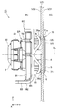
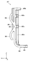
- FIG. 2E shows the center sensor 1T mounted in the fourth mounting hole V504 shown in FIG. 1D in an in-vehicle state.
- a right-handed XYZ Cartesian coordinate system is set with reference to the gravitational action direction in the vehicle-mounted state, as shown in FIGS. 2A and after. It is assumed that the Z-axis positive direction in the right-handed XYZ coordinate system shown in FIGS. 2A and later coincides with the Z-axis positive direction shown in FIGS. 1C and 1D.
- the positive Y-axis direction in the right-handed XYZ coordinate system is parallel to the thickness direction of the front bumper V3 at the mounting position, and is the direction from the bumper inner space SN to the bumper outer space SG.
- the “mounting position” is a position where the ultrasonic sensor 1 is mounted on the front bumper V3, and is typically the center position CP of the mounting hole V5.
- the bumper outer space SG is a space facing the bumper outer surface V31 and being outside the vehicle V in the vehicle-mounted state.
- the bumper interior space SN is a space that faces the bumper back surface V32 and is inside the vehicle V in the vehicle-mounted state.
- the X-axis direction in the right-handed XYZ coordinate system is orthogonal to the thickness direction of the front bumper V3 at the mounting position and is horizontal in the vehicle-mounted state.
- the X-axis positive direction in the right-handed XYZ coordinate system is assumed to substantially coincide with the X-axis positive direction shown in FIGS. 1C and 1D, or to form a predetermined small acute angle. That is, the X-axis direction in the right-handed XYZ coordinate system is a horizontal direction along the vehicle width direction, similar to the X-axis direction shown in FIGS. 1C and 1D.
- the direction parallel to the central axis CL constituting the directional axis of the ultrasonic sensor 1 is referred to as "axial direction”.
- the one on the positive direction side of the Y axis is referred to as the "tip portion in the axial direction”
- the one on the negative direction side of the Y axis is referred to.
- the base end in the axial direction is usually referred to as "axial dimension” below.
- any direction orthogonal to the axial direction is referred to as an "in-plane direction”.
- the shape of a certain member or part in a plane orthogonal to the central axis CL may be referred to as an "in-plane shape”.
- the "in-plane direction” includes a “diameter direction” and a “axial circumferential direction”.
- the "diameter direction” is a direction extending radially from the central axis CL. That is, the "diameter direction” is a direction that is orthogonal to the central axis CL and is separated from the central axis CL.
- the "diameter direction” is the direction in which the half straight line extends when a half straight line is drawn in the virtual plane starting from the intersection of the virtual plane orthogonal to the central axis CL and the central axis CL. ..
- the "diameter direction” is the radial direction of the virtual circle when a virtual circle is drawn in the virtual plane around the intersection of the virtual plane and the central axis CL.
- the "axial direction” is the circumferential direction of the virtual circle surrounding the central axis CL. The position in the axial direction is simply referred to as "axial position" below.
- the central axis CL is substantially parallel to the thickness direction of the front bumper V3 at the mounting position or a portion in the vicinity thereof. It is mounted on the vehicle V so as to be.
- the center sensor 1T is mounted on the vehicle V so that the center axis CL intersects the thickness direction of the front bumper V3 at the mounting position or a portion in the vicinity thereof in the vehicle-mounted state. It is installed.
- the sensor main body 2A which forms the main body portion of the ultrasonic sensor 1, includes a sensor case 3, an ultrasonic microphone 4, and a cushion member 5.
- the sensor body 2A is attached to the front bumper V3 by using the anti-vibration spacer 6, the bezel 7, and the retainer 8.
- the anti-vibration spacer 6 the bezel 7, and the retainer 8.
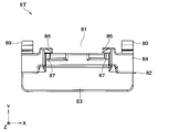
- (Sensor case) 3A and 3B show a state in which the retainer 8 is removed from the ultrasonic sensor 1 in the mounted state, the secondary assembly is taken out to the outside space SG side of the bumper, and then the bezel 7 is further removed from the secondary assembly.
- a sensor case 3 constituting a housing of an ultrasonic sensor 1, that is, a sensor body 2A, has a box-shaped portion 31, a connector portion 32, and a microphone support portion 33. ..
- the sensor case 3 is integrally formed of a hard synthetic resin such as polybutylene terephthalate, ABS resin, polypropylene, polycarbonate, and polystyrene.
- the box-shaped portion 31 is formed in a box shape having a longitudinal direction along the horizontal direction and a width direction along the vertical vertical direction and having a thin outer shape in the axial direction in the mounted state.
- the connector portion 32 is in the vehicle-mounted state in the connector extending direction DC, that is, substantially horizontal. Moreover, it extends diagonally backward. That is, the connector portion 32 is provided so as to be separated from the front bumper V3 in the mounted state toward the connector extension direction DC.
- the connector unit 32 has a configuration as a receptacle connector that can be attached to and detached from a plug connector (not shown) provided at the end of a wire harness for electrical connection with an external device such as an ECU.
- ECU is an abbreviation for Electronic Control Unit.
- the microphone support portion 33 extends axially from the other end of the box-shaped portion 31 in the longitudinal direction (that is, the right end in FIG. 3A).
- the microphone support portion 33 has a tubular shape that surrounds the central axis CL.
- the microphone support portion 33 is formed in a cylindrical shape with the central axis CL as the axis center.
- the circuit board 34 is housed inside the box-shaped portion 31.
- the circuit board 34 is electrically connected to the ultrasonic microphone 4 via the connection wiring 35.
- a cushion locking protrusion 36 and a bezel locking protrusion 37 are provided at the tip of the microphone support portion 33 in the axial direction.
- the cushion locking projection 36 is a projection protruding from the inner wall surface of the cylindrical inner surface surrounding the central axis CL in the microphone support portion 33 toward the central axis CL, and extends in the axial direction.
- the bezel locking projection 37 is a small projection protruding in the radial direction from the cylindrical outer wall surface surrounding the central axis CL in the microphone support portion 33, and is detachably engaged with the bezel 7 in the assembled state. It is formed to do.
- the microphone support portion 33 is provided with a plurality of bezel locking projections 37 at substantially the same position in the axial direction and different positions in the axial direction, respectively. Specifically, four bezel locking projections 37 are arranged at equal intervals in the axial circumferential direction.
- the pair of bezel locking projections 37 that are axially symmetrical with respect to the central axis CL are provided so that the virtual straight lines passing through them form an angle of 45 degrees with the X-axis and the Z-axis.
- An angle defining protrusion 38 is provided at the base end portion of the microphone support portion 33 in the axial direction.
- the angle defining protrusion 38 is a protrusion larger than the bezel locking protrusion 37, which is projected in the radial direction from the outer wall surface of the microphone support portion 33, and is provided at a predetermined position in the axial circumferential direction. There is.
- the ultrasonic microphone 4 has a columnar outer shape extending along the axial direction. Specifically, in the present embodiment, the ultrasonic microphone 4 is formed in a substantially columnar shape centered on the central axis CL.
- the ultrasonic microphone 4 includes an ultrasonic element 41 and a microphone case 42.
- the ultrasonic element 41 is a so-called electro-mechanical conversion element, and is formed of a thin-film piezoelectric element or the like.
- the ultrasonic element 41 is housed inside the microphone case 42.
- the microphone case 42 that constitutes the housing of the ultrasonic microphone 4 is formed in a bottomed cylindrical shape by a metal material such as aluminum.
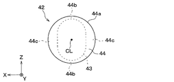
- the microphone case 42 has a diaphragm 43 and a side plate portion 44.
- the diaphragm 43 is formed in a thin plate shape having a thickness direction in the axial direction.
- the diaphragm 43 is provided so as to close the tip portion of the side plate portion 44 in the axial direction.
- the outer surface of the diaphragm 43 facing the bumper outer space SG in the mounted state or in the vehicle-mounted state is formed in a smooth flat shape.
- the ultrasonic element 41 is fixed to the inner surface of the diaphragm 43 on the back side of the outer surface.
- the diaphragm 43 is formed so that the in-plane shapes have a longitudinal direction and a lateral direction that are substantially orthogonal to each other. Specifically, in response to the above-mentioned directivity characteristics of the ultrasonic sensor 1, the diaphragm 43 has an oval or elliptical in-plane shape having a longitudinal direction along the vertical vertical direction in an in-vehicle state. doing.
- the side plate portion 44 is a substantially cylindrical portion of the microphone case 42 and extends in the axial direction.
- the side plate portion 44 that is, the side surface 44a forming the outer wall surface of the ultrasonic microphone 4 is formed in a cylindrical surface shape centered on the central axis CL.
- the side plate portion 44 has a thin-walled portion 44b and a thick-walled portion 44c.
- the thin-walled portion 44b is provided at a position corresponding to both ends of the diaphragm 43 in the longitudinal direction.
- the pair of thin-walled portions 44b are arranged symmetrically with the central axis CL in between while being arranged substantially vertically in the vertical direction in the vehicle-mounted state.
- the thick portion 44c is provided at a position corresponding to both ends of the diaphragm 43 in the lateral direction.
- the pair of thick portions 44c are arranged symmetrically with the central axis CL in between while being arranged in a substantially horizontal direction in a vehicle-mounted state.
- a pair of engaging grooves 45 are formed in the side plate portion 44.
- the engagement groove 45 is a square groove extending parallel to the Z-axis direction in the drawing, and is provided in the thick portion 44c.
- the pair of engaging grooves 45 are symmetrically arranged with the central axis CL in between.
- the cushion member 5 which is a vibration absorber is seamlessly and integrally formed of a synthetic resin-based elastic material such as silicone rubber.
- the cushion member 5 is provided on the sensor main body 2A, which is a primary assembly, as a component constituting the sensor main body 2A together with the ultrasonic microphone 4.
- the cushion member 5 is formed in a cylindrical shape surrounding the central axis CL. Specifically, in the present embodiment, the cushion member 5 has substantially the same outer diameter as the outer diameter of the microphone support portion 33 and substantially the same outer diameter as the outer diameter of the side plate portion 44 with the central axis CL as the axis center. It has a substantially cylindrical shape with an inner diameter. Further, the cushion member 5 is formed to have a larger axial dimension than the ultrasonic microphone 4.
- the cushion member 5 is fixed to the microphone support portion 33 at the supported portion 51 which is the base end portion in the axial direction.
- the supported portion 51 is provided with a locking groove 52 that opens in the radial direction.
- the locking groove 52 is a groove having a shape that engages with the cushion locking projection 36 provided on the microphone support portion 33, and extends in the axial direction.
- the microphone accommodating portion 53 which is a portion of the cushion member 5 on the tip side in the axial direction with respect to the supported portion 51, is configured to accommodate the ultrasonic microphone 4 over almost the entire axial direction. That is, the microphone accommodating portion 53 has a columnar internal space corresponding to the outer shape of the ultrasonic microphone 4 so as to cover the side surface 44a of the ultrasonic microphone 4.
- the microphone accommodating portion 53 is provided with a pair of engaging protrusions 54.
- the pair of engaging protrusions 54 are arranged so as to face each other with the central axis CL interposed therebetween.
- the engaging protrusion 54 has a shape that fits with the engaging groove 45, which is a square groove, and is a rectangular ridge portion in a cross-sectional view that protrudes toward the central axis CL, and is in the Z-axis direction in the drawing. It has been extended.
- the cushion member 5 is provided so as to elastically support the ultrasonic microphone 4 on the tip end side in the axial direction while being fixed to the sensor case 3 on the proximal end side in the axial direction. That is, the ultrasonic sensor 1 in the present embodiment elastically supports the ultrasonic microphone 4 on the sensor case 3 via the cushion member 5, thereby transmitting vibration between the sensor case 3 and the ultrasonic microphone 4. It is configured to suppress.
- the cushion member 5 is provided in the ultrasonic sensor 1 so as to be interposed between the bezel 7 provided so as to surround the side surface 44a of the ultrasonic microphone 4 and the ultrasonic microphone 4 in the vehicle-mounted state. .. That is, the cushion member 5 is configured to be interposed between the ultrasonic microphone 4 and the front bumper V3 to suppress vibration transmission between the ultrasonic microphone 4 and the front bumper V3.
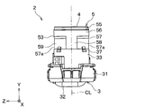
- the microphone accommodating portion 53 in the cushion member 5 has a tip portion 55, a first tubular portion 56, and a second tubular portion 57.
- the tip portion 55, the first cylindrical portion 56, and the second tubular portion 57 are arranged in this order in the axial direction.
- the tip portion 55 is a portion of the cushion member 5 on the most tip side in the axial direction, and has a conical outer wall surface and a cylindrical inner wall surface whose outer diameter decreases toward the tip end side in the axial direction. It is formed in a tapered shape with.
- the first cylindrical portion 56 is a portion adjacent to the tip portion 55 in the axial direction, and is provided on the tip side of the cushion member 5 in the axial direction.
- the first cylindrical portion 56 is configured to be sandwiched between the ultrasonic microphone 4 and the bezel 7 while being in contact with the ultrasonic microphone 4 and the bezel 7. That is, the first cylindrical portion 56 has a maximum thickness substantially the same as the dimension of the gap between the side surface 44a of the ultrasonic microphone 4 and the bezel 7 in the assembled state.
- the first tubular portion 56 is formed in a cylindrical shape having a constant thickness, that is, a radial dimension. In other words, the first cylindrical portion 56 is provided so as to abut the ultrasonic microphone 4 and the bezel 7 over the entire axial direction.
- the second tubular portion 57 is provided so as to be adjacent to the first tubular portion 56 on the proximal end side in the axial direction.
- the second cylindrical portion 57 has a pair of recesses 57a that open in the radial direction.
- the pair of recesses 57a are provided symmetrically with the central axis CL in between.
- the second cylindrical portion 57 is provided with a large diameter portion 58 and a small diameter portion 59.
- the large diameter portion 58 is provided so as to be sandwiched between the ultrasonic microphone 4 and the bezel 7 while being in contact with the ultrasonic microphone 4 and the bezel 7.
- the large diameter portion 58 has a partial cylindrical shape having a maximum thickness substantially equal to the dimension of the gap between the side surface 44a of the ultrasonic microphone 4 and the bezel 7 in the assembled state.
- the large diameter portion 58 is formed so that the diameters of the inner wall surface and the outer wall surface centered on the central axis CL substantially coincide with those of the first cylindrical portion 56.
- the small diameter portion 59 is provided so as to be adjacent to the large diameter portion 58 in the circumferential direction, and the outer diameter centered on the central axis CL is smaller than that of the large diameter portion 58.
- the small diameter portion 59 is formed to be thinner than the large diameter portion 58 by providing the recess 57a in the second tubular portion 57, and is provided at a position corresponding to the recess 57a in the axial direction. That is, the small diameter portion 59 is formed so that the gap with the bezel 7 is larger than that of the large diameter portion 58.
- the small diameter portion 59 is provided so that the diameter of the inner wall surface centered on the central axis CL is substantially the same as that of the first cylindrical portion 56.
- a pair of large diameter portions 58 are arranged so as to face each other with the central axis CL in between.
- a pair of small diameter portions 59 are arranged so as to face each other with the central axis CL in between. That is, one of the pair of large diameter portions 58, one of the pair of small diameter portions 59, the other one of the pair of large diameter portions 58, and the other one of the pair of small diameter portions 59. The ones are arranged adjacent to each other in this order in the axial circumferential direction.
- the cushion member 5 is configured such that the arrangement direction of the pair of large diameter portions 58 sandwiching the central axis CL and the arrangement direction of the pair of small diameter portions 59 sandwiching the central axis CL are orthogonal to each other. ..
- the large diameter portion 58 is formed so that the length in the axial circumferential direction is shorter than that of the small diameter portion 59. Further, as is clear from the illustrations in FIGS. 3A to 5, the large diameter portion 58 is provided at a position corresponding to both ends of the diaphragm 43 in the lateral direction. On the other hand, the small diameter portion 59 is provided at a position corresponding to both ends of the diaphragm 43 in the longitudinal direction.
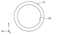
- the anti-vibration spacer 6 is a thin plate-shaped and ring-shaped member having a thickness direction in the axial direction, and is formed of a synthetic resin-based elastic material such as silicone rubber. Specifically, in the present embodiment, the anti-vibration spacer 6 has a shape in which a spacer through hole 61, which is a circular through hole, is formed at the center position of the disk-shaped member.
- the anti-vibration spacer 6 has the flange portion 71 and the front bumper V3 described later in the bezel 7 in the vehicle-mounted state so as to suppress the vibration transmission between the bezel 7 and the front bumper V3. It is provided between. That is, the anti-vibration spacer 6 is sandwiched between the back surface 71a, which is the surface of the flange portion 71 facing the front bumper V3, and the bumper outer surface V31 so as to be interposed between the bezel 7 and the front bumper V3 in the mounted state. Has been done.
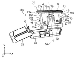
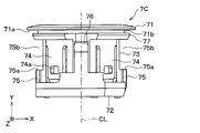
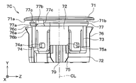
- FIG. 7A shows a secondary assembly provided in the corner sensor 1C shown in FIG. 2A.
- FIG. 7B shows a secondary assembly provided in the center sensor 1T shown in FIG. 2E.
- 8A-8D show the schematic configuration of the corner bezel 7C shown in FIG. 7A.
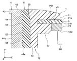
- FIG. 9 is an enlarged cross-sectional view of the periphery of the flange portion 71 of the bezel 7 in the mounted state or the vehicle-mounted state.
- 10A-10C show the schematic configuration of the center bezel 7T shown in FIG. 7B.
- the bezel 7 is a component used for attaching an ultrasonic sensor 1 to a front bumper V3, which is a plate-shaped vehicle body component, and is integrally formed of a hard synthetic resin.
- the bezel 7 is inserted into the mounting hole V5 shown in FIG. 1B or the like in the mounted state.
- the corner bezel 7C sets the mounting posture of the corner sensor 1C to the first posture by engaging with the bumper-side engaging portion V52 provided in the first mounting hole V501. It is configured as follows. Further, the corner bezel 7C is configured to set the mounting posture of the corner sensor 1C to the second posture by engaging with the bumper-side engaging portion V52 provided in the second mounting hole V502.
- the center bezel 7T is configured to set the mounting posture of the center sensor 1T to the third posture by engaging with the bumper-side engaging portion V52 provided in the third mounting hole V503. Further, the center bezel 7T is configured to set the mounting posture of the center sensor 1T to the fourth posture by engaging with the bumper side engaging portion V52 provided in the fourth mounting hole V504.
- a flange portion 71 is provided at the tip portion of the corner bezel 7C in the axial direction.
- the flange portion 71 is a ring-shaped portion having a thickness direction in the axial direction, and projects in the radial direction.
- the corner bezel 7C is formed so that the normal direction of the back surface 71a of the flange portion 71 is substantially parallel to the central axis CL.
- the flange portion 71 is formed in the shape of a disk having a circular through hole formed at the center position.
- the flange portion 71 has an outer diameter larger than the inner diameter of the mounting hole V5. That is, as shown in FIG. 2A and the like, the flange portion 71 is provided so as to face the peripheral portion of the mounting hole V5 on the bumper outer surface V31 with the anti-vibration spacer 6 interposed therebetween, as shown in FIG. 2A and the like. There is.
- the flange portion 71 has an inner diameter substantially the same as the outer diameter of the tip portion 55 of the cushion member 5. That is, as shown in FIG. 9, the flange portion 71 is configured to sandwich the tip portion 55 of the cushion member 5 with the side surface 44a of the microphone case 42.
- a spacer accommodating groove 71b for accommodating the anti-vibration spacer 6 is provided so as to open in the radial direction at a position adjacent to the flange portion 71 on the proximal end side of the flange portion 71 in the axial direction.
- the spacer accommodating groove 71b is formed so as to have a width, that is, an axial dimension corresponding to the thickness of the anti-vibration spacer 6, and a depth, that is, a radial dimension corresponding to the diameter of the spacer through hole 61 in the anti-vibration spacer 6. There is.
- the spacer accommodating groove 71b extends over the entire bezel 7 in the axial direction.
- the spacer accommodating groove 71b is provided between the flange portion 71 and the cylindrical portion 72. That is, the flange portion 71 protrudes in the radial direction at one end portion, that is, the tip portion of the cylindrical portion 72 extending in the axial direction.
- the flange portion 71 and the tubular portion 72 are seamlessly integrally formed of the same material.
- the tubular portion 72 is configured to be housed in the mounting hole V5 while surrounding the ultrasonic microphone 4 and the cushion member 5 in the assembled state and the mounting state.
- the tubular portion 72 has an outer diameter slightly smaller than the inner diameter of the mounting hole V5 and an inner diameter slightly larger than the outer diameter of the microphone support portion 33.
- the main body portion 73 which is a tubular portion including the central portion in the axial direction of the tubular portion 72, extends along the central axis CL.
- the sensor locking piece 74 is provided on the main body 73.
- the sensor locking piece 74 is a cantilever-shaped tongue piece having a thickness direction in the radial direction, and extends from the tip end portion to the base end portion in the axial direction of the main body portion 73. That is, the sensor locking piece 74 is formed so as to be elastically deformable in such a manner that the tip portion in the axial direction is a fixed end and the base end portion in the axial direction is a free end, and the free end moves in the radial direction.
- the sensor locking piece 74 in the corner bezel 7C extends in a direction substantially parallel to the normal direction of the back surface 71a of the flange portion 71.
- a locking hole 74a that penetrates the sensor locking piece 74 in the thickness direction is provided on the free end side of the sensor locking piece 74.
- the locking hole 74a is formed so as to be detachably engaged with the bezel locking projection 37 provided on the microphone support portion 33 in the assembled state.
- the main body 73 is provided with the same number of sensor locking pieces 74 as the bezel locking projections 37 so as to be arranged in the axial circumferential direction. That is, in the present embodiment, the four sensor locking pieces 74 are arranged at equal intervals in the axial circumferential direction.
- the plurality of sensor locking pieces 74 provided on the corner bezel 7C are formed to have the same length, that is, the axial dimension.
- the main body 73 is provided with a projecting portion 75.
- the projecting portion 75 projects from the main body portion 73 in a direction intersecting the central axis CL.
- the projecting portion 75 is integrally connected to the main body portion 73.
- the main body portion 73 and the projecting portion 75 are seamlessly integrally formed of the same material.
- the bezel 7 is provided with a pair of projecting portions 75.
- the pair of projecting portions 75 are arranged symmetrically with respect to the central axis CL. That is, each of the pair of projecting portions 75 projects in the direction opposite to the central axis CL.
- Each of the pair of projecting portions 75 is arranged between the two sensor locking pieces 74 in the axial circumferential direction.
- the protruding portion 75 is projected along the protruding direction of the flange portion 71.
- each of the pair of projecting portions 75 projects in the radial direction from the base end portion in the axial direction of the main body portion 73.
- the retainer contact surface 75a which is the end surface of the projecting portion 75 on the distal end side in the axial direction, is formed in a smooth planar shape having a normal direction parallel to the central axis CL. That is, the retainer contact surface 75a is provided so as to be substantially parallel to the back surface 71a of the flange portion 71.
- a retainer insertion groove 75b is formed on the tip side in the axial direction from the retainer contact surface 75a.
- the retainer insertion groove 75b is a space through which the retainer 8 is inserted when the ultrasonic sensor 1 is attached to the front bumper V3, and is provided so as to open in the radial direction. That is, the projecting portion 75 is formed so as to sandwich the retainer 8 inserted into the retainer insertion groove 75b with the bumper back surface V32 in the mounted state.
- the pair of retainer insertion grooves 75b are arranged symmetrically with respect to the central axis CL.
- Each of the pair of retainer insertion grooves 75b has a square groove-like structure extending in the Z-axis direction in the drawing. That is, as shown in FIG. 1D, the projecting portion 75 is formed so as to define the attachment / detachment direction of the retainer 8 which is the fixture in the present disclosure with respect to the bezel 7 in a direction parallel to the Z axis in the drawing. There is.
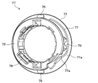
- a temporary assembly piece 76 is provided on the tubular portion 72.
- the temporary assembly piece 76 is a cantilever-shaped tongue piece having a thickness direction in the radial direction, and extends axially from the base end portion in the axial direction of the tubular portion 72 toward the flange portion 71. There is. That is, the temporary assembly piece 76 is formed so as to be elastically deformable in such a manner that the base end portion in the axial direction is a fixed end and the tip end portion in the axial direction is a free end, and the free end moves in the radial direction.
- the bezel 7 is provided with a pair of temporary assembly pieces 76.
- the pair of temporary assembly pieces 76 are arranged symmetrically with respect to the central axis CL.
- the bezel 7 is configured such that the arrangement direction of the pair of temporary assembly pieces 76 sandwiching the central axis CL is orthogonal to the arrangement direction of the pair of projecting portions 75 sandwiching the central axis CL. ..
- Each of the pair of temporary assembly pieces 76 is arranged between the two sensor locking pieces 74 in the axial circumferential direction. That is, the first sensor locking piece 74, the first projecting portion 75, the second sensor locking piece 74, the first temporary assembly piece 76, and the third sensor engagement.
- the stop piece 74 and the second projecting portion 75 are arranged at equal intervals in the axial circumferential direction in this order. Further, the second projecting portion 75, the fourth sensor locking piece 74, the second temporary assembly piece 76, and the first sensor locking piece 74 are arranged in this order in the axial circumferential direction. Are evenly spaced.
- a temporary assembly protrusion 76a protruding in the radial direction is provided at the free end of the temporary assembly piece 76, that is, the tip portion in the axial direction.
- the temporary assembly protrusion 76a is configured so that the secondary assembly can be held in the temporary assembly state.
- the temporary assembly state is a state in which the bezel 7 in the secondary assembly is inserted into the mounting hole V5, so that the secondary assembly is temporarily held by the front bumper V3 in a predetermined temporary assembly posture.
- the anti-vibration spacer 6 contacts or approaches the bumper outer surface V31 of the front bumper V3, and the connector portion 32 is rear-viewed along the X-axis direction in the drawing as shown in FIG. 1D.
- the posture of the secondary assembly is such that it extends.
- the temporarily assembled state corresponds to a state in which the retainer 8 is removed from the ultrasonic sensor 1 in the vehicle-mounted state.
- the temporary assembly projection 76a has a wedge-shaped outer shape having an inclined surface 76b and a flange facing surface 76c.
- the inclined surface 76b is a surface of the temporary assembly projection 76a that is exposed in the radial direction, and is provided so as to be separated from the central axis CL toward the tip end side in the axial direction.
- the flange facing surface 76c is an end surface of the temporary assembly projection 76a and is provided so as to face the back surface 71a of the flange portion 71.
- the tip-side projecting portion 77 is projected in the radial direction while being integrally connected to the main body 73.
- the tip-side projecting portion 77 is the most tip-side portion of the tubular portion 72 in the axial direction, and extends in the axial circumferential direction.
- the main body portion 73 and the tip-side projecting portion 77 are seamlessly and integrally formed of the same material. As shown in FIG. 9, the tip-side projecting portion 77 is provided so as to be in close contact with the inner edge V51 of the mounting hole V5 in the mounted state.
- the tip side projecting portion 77 is provided between the spacer accommodating groove 71b and the retainer insertion groove 75b in the axial direction. That is, the tip-side projecting portion 77 is provided so as to be adjacent to the spacer accommodating groove 71b and the retainer insertion groove 75b in the axial direction. Therefore, the spacer accommodating groove 71b is formed so as to include a gap between the flange portion 71 and the tip-side projecting portion 77. Further, the retainer insertion groove 75b is formed by a space between the projecting portion 75 and the tip-side projecting portion 77.
- the tip-side protruding portion 77 has a bezel-side engaging portion 77a as a device-side engaging portion.
- the bezel-side engaging portion 77a is formed so as to engage with the bumper-side engaging portion V52 shown in FIG. 1D as the vehicle body-side engaging portion. That is, the bezel-side engaging portion 77a is an uneven portion provided on the bezel 7 and has a shape corresponding to the shape of the bumper-side engaging portion V52.
- the bezel-side engaging portion 77a in the corner bezel 7C has a position in the axial circumferential direction in the assembled state on the Z-axis negative direction side of the two bezel locking projections 37 arranged on the connector portion 32 side of the central axis CL. It is provided so that it is in a position corresponding to the one. That is, as shown in FIG. 1D, the bezel-side engaging portion 77a in the corner bezel 7C engages with the bumper-side engaging portion V52 provided in the first mounting hole V501 to cause the corner sensor 1C to engage. It is formed at a position where the mounting posture is the first posture. Further, the bezel-side engaging portion 77a is formed at a position where the mounting posture in the corner sensor 1C becomes the second posture by engaging with the bumper-side engaging portion V52 provided in the second mounting hole V502. There is.
- the bezel-side engaging portion 77a has a bezel-side concave portion 77b and a pair of bezel-side convex portions 77c.
- the bezel-side concave portion 77b has a shape corresponding to the bumper-side convex portion V53. That is, the bezel-side recess 77b is a recess that opens in the radial direction, and is provided at a predetermined position in the axial direction of the tip-side projecting portion 77 extending in the axial direction.
- the bezel-side convex portion 77c has a shape corresponding to the bumper-side concave portion V54.
- the bezel-side convex portion 77c is a portion formed in a relatively convex shape at both ends of the bezel-side concave portion 77b in the axial direction by providing the bezel-side concave portion 77b.
- An angle-regulating recess 78 is formed in the cylindrical portion 72.
- the angle defining recess 78 is provided so as to open in the axial direction at the position closest to the proximal end side in the axial direction of the tubular portion 72. Further, the angle defining recess 78 is provided at the innermost position in the radial direction of the tubular portion 72 so as to open toward the central axis CL.
- the angle defining recess 78 has a concave shape corresponding to the convex shape of the angle defining protrusion 38 so as to accommodate the angle defining protrusion 38 provided on the microphone support portion 33 in the assembled state.
- angle defining recess 78 there is only one angle defining recess 78 at a predetermined position in the axial circumferential direction of the cylindrical portion 72 so as to define the relative rotation angle of the bezel 7 with respect to the sensor case 3 about the central axis CL in the assembled state. It is provided. Specifically, in the present embodiment, the angle defining recess 78 is arranged at a position corresponding to one of the four sensor locking pieces 74 in the axial circumferential direction. As shown in FIG. 8D, the angle-determining recess 78 in the corner bezel 7C is arranged on the side opposite to the bezel-side engaging portion 77a with the central axis CL in between.
- the tubular portion 72 is provided with a retainer engaging portion 79.
- the retainer engaging portion 79 is configured to be detachably engaged with the retainer 8 in the mounted state to prevent the retainer 8 from being disengaged from the bezel 7.
- the retainer engaging portion 79 is formed as a concave portion that opens in the radial direction and has a shape that engages with a convex portion provided on the retainer 8 side.
- the pair of retainer engaging portions 79 are arranged at symmetrical positions with the central axis CL in between. Specifically, one retainer engaging portion 79 is provided for each of the pair of projecting portions 75.
- center bezel 7T As the second tubular component in the present disclosure will be described.
- the center bezel 7T has the same configuration as the corner bezel 7C except as described in detail below.
- the corner bezel 7C and the center bezel 7T are formed so that the crossing angles of the central axis CL with respect to the front bumper V3 in the mounted state are different from each other.
- the center bezel 7T is formed so that the normal direction of the back surface 71a of the flange portion 71 intersects the central axis CL. That is, the flange portion 71 of the center bezel 7T projects in a direction intersecting the radial direction.
- the tubular portion 72 has a shape in which one end side, that is, the tip end side in the axial direction of the cylinder is cut off diagonally by an inclined cutting surface.
- the flange portion 71 is provided on the inclined cut surface side of the tubular portion 72 in the axial direction.
- the sensor locking piece 74 extends in the axial direction, which is the direction intersecting the normal direction of the back surface 71a of the flange portion 71. Therefore, the pair of sensor locking pieces 74 arranged on both sides of the temporary assembly piece 76 in the axial circumferential direction have different lengths, that is, axial dimensions. On the other hand, as shown in FIG. 10B, the pair of sensor locking pieces 74 arranged on both sides of the projecting portion 75 in the axial direction are formed to have the same length.
- one of the pair of projecting portions 75 projects in the positive direction of the X-axis in the figure along the projecting direction of the flange portion 71.
- the other of the pair of projecting portions 75 projects in the negative direction of the X-axis in the drawing along the projecting direction of the flange portion 71.
- One of the pair of projecting portions 75 on the positive direction side of the X axis in the drawing is formed to have a longer axial dimension than the other.
- the center bezel 7T is also provided so that the retainer contact surface 75a is substantially parallel to the back surface 71a of the flange portion 71. Therefore, the retainer contact surface 75a in the center bezel 7T is formed so that the normal direction intersects the central axis CL.
- the distance between the retainer contact surface 75a and the back surface 71a of the flange portion 71 is set to be different between the corner bezel 7C and the center bezel 7T.
- the "misinstallation" in this case is an attempt to attach the center retainer 8T to the corner bezel 7C, or an attempt to attach the corner retainer 8C to the center bezel 7T.
- the center bezel 7T is formed so that the distance between the retainer contact surface 75a and the back surface 71a of the flange portion 71 is smaller than that of the corner bezel 7C. That is, the center bezel 7T is formed so that the width of the retainer insertion groove 75b, that is, the dimension in the Y-axis direction in the drawing is smaller than that of the corner bezel 7C.
- the bezel-side engaging portion 77a is the corner bezel 7C and the center bezel 7T relative to the angle defining recess 78 in the axial direction. It is provided so that the position is different.
- the "erroneous mounting” means that the corner sensor 1C is to be mounted in the third mounting hole V503 or the fourth mounting hole V504, or the center sensor 1T is mounted in the first mounting hole V501 or the first mounting hole V501 or the fourth mounting hole V504, referring to FIG. 1D. (Ii) It is intended to be mounted in the mounting hole V502.
- the bezel-side engaging portion 77a in the center bezel 7T has a shorter axial dimension than the temporary assembly piece 76 provided on the positive side of the Z-axis in FIG. 10A in the axial circumferential direction. It is provided at a position corresponding to the sensor locking piece 74 arranged between the protruding portion 75 on the negative direction side.
- the bezel-side engaging portion 77a in the center bezel 7T has the axial circumferential position in the assembled state on the Z-axis positive direction side of the two bezel locking projections 37 arranged on the connector portion 32 side of the central axis CL. It is provided so that it is in a position corresponding to the one. That is, as shown in FIG. 1D, the bezel-side engaging portion 77a in the center bezel 7T engages with the bumper-side engaging portion V52 provided in the third mounting hole V503 in the center sensor 1T. It is formed at a position where the mounting posture is the third posture. Further, the bezel-side engaging portion 77a is formed at a position where the mounting posture of the center sensor 1T becomes the fourth posture by engaging with the bumper-side engaging portion V52 provided in the fourth mounting hole V504. There is.
- the retainer 8 as the sensor fixture in the present disclosure attaches the ultrasonic sensor 1 to the temporarily assembled secondary assembly inserted through the mounting hole V5. It is configured to be fixed to the front bumper V3. Specifically, the retainer 8 is inserted between the projecting portion 75 and the front bumper V3 with the cylindrical portion 72 inserted through the mounting hole V5, so that the retainer 8 is inserted between the projecting portion 75 and the front bumper V3. It is designed to be sandwiched between.
- the retainer 8 is integrally formed of a hard synthetic resin.
- FIG. 11A to 11D show a schematic configuration of the corner retainer 8C.
- 12A to 12D show a schematic configuration of the center retainer 8T.
- the rear view of the center retainer 8T shown in FIG. 12A corresponds to the rear view of the corner retainer 8C shown in FIG. 11A.
- the side view of the center retainer 8T shown in FIG. 12B corresponds to the side view of the corner retainer 8C shown in FIG. 11B.
- the plan view of the center retainer 8T shown in FIG. 12C corresponds to the plan view of the corner retainer 8C shown in FIG. 11C.
- the front view of the center retainer 8T shown in FIG. 12D corresponds to the front view of the corner retainer 8C shown in FIG. 11D.
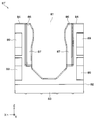
- the corner retainer 8C and the center retainer 8T are formed in a substantially U shape in front view, which opens at the opening 81 in the positive direction of the Z axis.
- the retainer main body 82 constituting the main body portion of the corner retainer 8C and the center retainer 8T has a connecting portion 83 extending in the X-axis direction in the drawing and a Z-axis positive in the drawing from both ends of the connecting portion 83. It has a pair of extending portions 84 extending in the direction.
- the connecting portion 83 is provided so as to connect one ends of the pair of extending portions 84 to each other.
- the pair of extension portions 84 are provided so as to extend in a direction intersecting the central axis CL and face each other with the central axis CL in between.
- the connecting portion 83 and the pair of extending portions 84 form the above-mentioned substantially U-shape.
- the pair of extending portions 84 are provided so as to sandwich the tubular portion 72 while accommodating the tubular portion 72 in the bezel 7 in the inner space formed between them and opened by the opening 81. .. Further, the corner retainer 8C and the center retainer 8T are configured so that the arrangement direction of the pair of extending portions 84 sandwiching the central axis CL is orthogonal to the arrangement direction of the pair of small diameter portions 59 sandwiching the central axis CL. There is.
- the retainer main body 82 is formed in a substantially J shape in a side view by the connecting portion 83 and the pair of extending portions 84. That is, the connecting portion 83 is formed in a plate shape having a thickness direction in the Z-axis direction in the drawing.
- the extension portion 84 is formed in a plate shape having a thickness direction in the axial direction.
- the extension portion 84 is reinforced by a rib-shaped reinforcing portion 85 projecting in the axial direction.
- the reinforcing portion 85 has a first rib 85a and a second rib 85b.
- the first rib 85a extends in the width direction of the extension portion 84, that is, at an intermediate position in the X-axis direction in the drawing, in the Z-axis direction in the drawing, which is the extension direction of the extension portion 84.
- the second rib 85b extends outward from the first rib 85a in the width direction of the extending portion 84.
- the extension portion 84 has a bezel contact portion 86. As shown in FIGS. 11A and 12A, the bezel contact portion 86 is a portion inside the first rib 85a in the width direction of the extension portion 84, and is opened at the opening 81. It is projected toward the inner space.
- the bezel contact portion 86 has a bezel contact surface 87.
- the bezel contact surface 87 is a surface that comes into contact with the retainer contact surface 75a of the bezel 7 when the mounting state is formed, and is a smooth flat surface having a normal direction parallel to the central axis CL in the mounting state. It is formed.
- each of the pair of extending portions 84 is provided with a bezel engaging portion 88.
- the bezel engaging portion 88 is formed so as to be detachably engaged with the retainer engaging portion 79 shown in FIGS. 8D and 10C.
- the bezel engaging portion 88 has a shape as a convex portion that engages with the concave portion in the retainer engaging portion 79. That is, each of the pair of bezel engaging portions 88 is projected toward the space for accommodating the bezel 7 between the pair of extending portions 84.
- the corner retainer 8C and the center retainer 8T have a plurality of elastic portions 89.
- the elastic portion 89 is a cantilever-shaped leaf spring portion that protrudes from the retainer main body 82 on the positive direction side of the Y axis in the drawing, and is from a substantially central portion in the longitudinal direction of the extension portion 84 in the positive direction of the Y axis. It is extended in the direction of inclination.
- each of the pair of extending portions 84 is provided with a pair of elastic portions 89 in a gull-wing shape.
- the elastic portion 89 is configured to be elastically deformed while being in contact with the bumper back surface V32 in the mounted state.
- the distance between the retainer contact surface 75a and the back surface 71a in the flange portion 71 is set between the corner bezel 7C and the center bezel 7T. It is set to be different.
- the offset state of the bezel contact surface 87 that is, the distance from the reference surface is set to be different between the corner retainer 8C and the center retainer 8T.
- the "reference plane” is a virtual plane parallel to the XZ plane in the drawing, which approximates the position most distant from the extension portion 84 in all the elastic parts 89 in the natural state.
- the center bezel 7T is formed so that the distance between the retainer contact surface 75a and the back surface 71a of the flange portion 71 is smaller than that of the corner bezel 7C.
- the center retainer 8T is formed so that the distance of the bezel contact surface 87 from the reference surface is smaller than that of the corner retainer 8C.
- the ultrasonic sensor 1 can be attached to and detached from the front bumper V3 and the rear bumper V4 in a state where the front bumper V3 and the rear bumper V4 are usually removed from the vehicle body V1. Therefore, in the actual mounting method or mounting process, the Z-axis positive direction may be different from the upward direction.
- the sensor body 2A shown in FIGS. 3A and 3B is formed. Further, the anti-vibration spacer 6 shown in FIG. 6A and the like is attached to the corner bezel 7C and the center bezel 7T shown in FIGS. 8A and 10A.
- the ultrasonic microphone 4 and the cushion member 5 in the sensor body 2A are inserted into the corner bezel 7C to which the anti-vibration spacer 6 is mounted from the base end side in the axial direction of the tubular portion 72.
- the ultrasonic microphone 4 and the cushion member 5 in the sensor body 2A are inserted into the center bezel 7T to which the anti-vibration spacer 6 is mounted from the proximal end side in the axial direction of the tubular portion 72.
- the corner bezel 7C is attached to the sensor body 2A to form the secondary assembly shown in FIG. 7A. Further, by mounting the center bezel 7T on the sensor body 2A, the secondary assembly shown in FIG. 7B is formed.
- the cushion member 5 is housed in a tubular portion 72 of the bezel 7 while surrounding the ultrasonic microphone 4.
- the relative rotation angle or rotation posture of the corner bezel 7C and the center bezel 7T about the central axis CL with respect to the sensor main body 2A is defined by the engagement between the angle defining protrusion 38 and the angle defining recess 78.
- the axial position of the bezel-side engaging portion 77a is set to a predetermined position. That is, the bezel-side engaging portion 77a differs between the secondary assembly for the corner sensor 1C shown in FIG. 7A and the secondary assembly for the center sensor 1T shown in FIG. 7B in the axial circumferential direction. Placed in position.
- the bezel-side engaging portion 77a is the Z-axis of the two bezel locking projections 37 arranged on the connector portion 32 side of the central axis CL. It is the position corresponding to the one on the negative direction side.
- the bezel-side engaging portion 77a is on the Z-axis positive direction side of the two bezel locking projections 37 arranged on the connector portion 32 side with respect to the central axis CL. It will be the position corresponding to the one.
- the secondary assembly shown in FIG. 7A is inserted into the first mounting hole V501 from the bumper outer space SG side with the connector portion 32 at the head. Further, the secondary assembly shown in FIG. 7A is inserted into the second mounting hole V502 from the bumper outer space SG side with the connector portion 32 at the head. Similarly, the secondary assembly shown in FIG. 7B is inserted into the third mounting hole V503 from the bumper outer space SG side with the connector portion 32 at the head. Further, the secondary assembly shown in FIG. 7B is inserted into the fourth mounting hole V504 from the bumper outer space SG side with the connector portion 32 at the head.
- the bezel 7 is held by the front bumper V3 by the flange portion 71 and the flange facing surface 76c in the temporary assembly projection 76a, so that the secondary assembly is in the temporary assembly state.
- the retainer 8 is in a detachable posture on the SN side of the space inside the bumper.
- the attachment / detachment posture is a posture in which the opening 81 opens in the positive direction of the Z axis in the drawing and the elastic portion 89 faces the back surface V32 of the bumper.
- the opening 81 in the corner retainer 8C in the detachable posture is brought closer to the corner bezel 7C in the secondary assembly in the temporarily assembled state. Then, the corner retainer 8C is slid in the retainer mounting direction DS as shown in FIG. 1D.
- the opening 81 in the center retainer 8T in the detachable posture is brought closer to the center bezel 7T in the secondary assembly in the temporarily assembled state. Then, the center retainer 8T is slid in the retainer mounting direction DS as shown in FIG. 1D.
- each of the pair of extension portions 84 is placed in the retainer insertion groove 75b in the retainer mounting direction DS. Slide. Then, the corner retainer 8C and the center retainer 8T are pushed into the retainer mounting direction DS until the tubular portion 72 and the connecting portion 83 are in close contact with each other.
- the bezel contact surface 87 stably contacts the retainer contact surface 75a. Further, the retainer engaging portion 79 provided in the tubular portion 72 and the bezel engaging portion 88 provided in the extending portion 84 are engaged with each other. In this state, the retainer 8 is sandwiched between the projecting portion 75 on the bezel 7 and the bumper back surface V32 by the action of the elastic restoring force of the elastic portion 89.
- the retainer 8 is attached to the secondary assembly in the temporarily assembled state.
- the corner sensor 1C and the center sensor 1T are attached to the front bumper V3.
- the vehicle-mounted posture of the ultrasonic sensor 1 may be different depending on the mounting position in the vehicle width direction due to the convenience of wiring or the like.
- the corner sensor 1C has a front bumper V3 so that the connector extension direction DC faces the outside in the vehicle width direction, that is, the side opposite to the vehicle center surface PC. Can be attached to.
- the center sensor 1T is attached to the front bumper V3 so that the connector extension direction DC faces the inside in the vehicle width direction, that is, the vehicle center surface PC.
- the corner sensor 1C mounted in the first mounting hole V501 should direct the connector extension direction DC in the negative direction of the X axis in the drawing.
- the connector extension direction DC in the corner sensor 1C is directed in the positive direction of the X axis in the drawing, erroneous installation will occur.
- the ultrasonic sensor 1 may be formed into a different shape depending on the vehicle-mounted position.
- the corner sensor 1C and the center sensor 1T have different angles of intersection of the directional axis, that is, the central axis CL with respect to the front bumper V3 in the vehicle-mounted state.
- the corner bezel 7C and the center bezel 7T are formed in different shapes.
- the corner sensor 1C should be mounted in the first mounting hole V501.
- the directional shaft does not face a predetermined direction, resulting in erroneous mounting.
- the corner sensor 1C and the center sensor 1T have different shapes, it is possible to satisfactorily avoid erroneous mounting.
- the corner sensor 1C and the center sensor 1T have different shapes to the extent that the diameter or shape of the mounting hole V5 is different, the manufacturing cost will increase significantly.
- the outer diameter shape or the surface color of the flange portion 71 in the bezel 7 is different between the corner sensor 1C and the center sensor 1T, in addition to the increase in manufacturing cost, the entire design of the vehicle V may be adversely affected.
- the mounting hole V5 has a configuration in which one bumper-side engaging portion V52 is provided at a predetermined position in the circumferential direction.
- the bezel 7 has a configuration in which one bezel-side engaging portion 77a that engages with the bumper-side engaging portion V52 is provided at a predetermined position in the axial circumferential direction.
- the shape of the mounting hole V5 is common, and the circumferential position surrounding the center position CP of the bumper side engaging portion V52 is different to avoid erroneous mounting.
- the circumferential position of the bumper-side engaging portion V52 differs by 180 degrees between the first mounting hole V501 and the second mounting hole V502.
- the circumferential position of the bumper-side engaging portion V52 differs by 180 degrees between the third mounting hole V503 and the fourth mounting hole V504.
- the circumferential position of the bumper side engaging portion V52 differs by 90 degrees between the first mounting hole V501 and the third mounting hole V503.
- the circumferential position of the bumper-side engaging portion V52 differs by 90 degrees between the second mounting hole V502 and the fourth mounting hole V504.
- the corner bezel 7C and the center bezel 7T differ in the circumferential position of the bezel-side engaging portion 77a by 90 degrees.
- the connector extension direction DC is the direction along the Z axis in the drawing.
- the connector extension direction DC is the direction along the Z axis in the drawing.
- the bumper side engaging portion V52 is formed in a rounded shape. Therefore, even if the front bumper V3 is made of a metal plate material, it is possible to satisfactorily form the mounting hole V5 capable of avoiding erroneous mounting while avoiding an increase in manufacturing cost as much as possible.
- the bumper-side engaging portion V52 is formed as a bumper-side convex portion V53 projecting toward the inside of the mounting hole V5. That is, even if the bumper-side engaging portion V52 is provided, the hole diameter of the mounting hole V5 is not expanded as compared with the case where the bumper-side engaging portion V52 is not provided. Therefore, the expansion of the outer diameter of the flange portion 71 for covering the mounting hole V5 so that the mounting hole V5 is not exposed to the outside can be satisfactorily avoided. Therefore, the expansion of the bezel 7's physique can be satisfactorily avoided.
- the circumferential position of the bumper-side convex portion V53 as the bumper-side engaging portion V52 is indicated by an azimuth angle based on the direction from the center position CP toward the Z-axis positive direction in the figure. It is possible. When such an azimuth becomes a multiple of 90 degrees as shown by the alternate long and short dash line in the figure, when the secondary assembly is inserted into the mounting hole V5 from the bumper outer space SG side with the connector portion 32 at the head. The bumper-side convex portion V53 interferes with various parts in the secondary assembly.
- the bumper-side convex portions V53 interfere with both ends of the box-shaped portion 31 in the sensor case 3 in the width direction. Further, for example, when the azimuth becomes 90 degrees or 270 degrees, the bumper side convex portion V53 interferes with the portion of the protruding portion 75 of the bezel 7 where the retainer engaging portion 79 is provided.
- the azimuth angle corresponding to the circumferential position of the bumper-side convex portion V53 as the bumper-side engaging portion V52 is set so as not to be a multiple of 90 degrees.
- the mounting hole V5 has a configuration in which one bumper-side engaging portion V52 is provided at an azimuth angle of 45 degrees, 135 degrees, 225 degrees, or 315 degrees. Therefore, it is possible to avoid erroneous installation as much as possible with the minimum processing.
- the first mounting hole V501 is provided with bumper-side convex portions V53 as bumper-side engaging portions V52 at two locations having azimuth angles of 225 degrees and 315 degrees. Be done.
- the second mounting hole V502 is provided with bumper-side convex portions V53 as bumper-side engaging portions V52 at two locations having azimuth angles of 45 degrees and 135 degrees.
- the corner bezel 7C is also provided with two bezel-side engaging portions 77a.
- the third mounting hole V503 and the fourth mounting hole V504 are each provided with only one bumper-side convex portion V53 as the bumper-side engaging portion V52, as in the present embodiment.
- the center bezel 7T is also provided with only one bezel-side engaging portion 77a.
- an error in the mounting angle when mounting the corner sensor 1C in the first mounting hole V501 and the second mounting hole V502 can be satisfactorily avoided as in the present embodiment. Further, an error in the mounting angle when mounting the center sensor 1T in the third mounting hole V503 and the fourth mounting hole V504 can be satisfactorily avoided.
- the center sensor 1T provided with the center bezel 7T having only one bezel-side engaging portion 77a cannot be mounted on the first mounting hole V501 and the second mounting hole V502 provided with two bumper-side convex portions V53. Is. However, the corner sensor 1C provided with the corner bezel 7C provided with two bezel-side engaging portions 77a is provided in the third mounting hole V503 and the fourth mounting hole V504 provided with only one bumper-side convex portion V53. It can be installed. Therefore, in such another configuration, erroneous mounting between the corner sensor 1C and the center sensor 1T cannot be completely avoided.
- the distance between the retainer contact surface 75a and the back surface 71a of the flange portion 71 is different between the corner bezel 7C and the center bezel 7T.
- the offset state of the bezel contact surface 87 differs between the corner retainer 8C and the center retainer 8T.
- the shape change other than the shape change due to the inclination of the flange portion 71 with respect to the central axis CL is minimized in the corner bezel 7C and the center bezel 7T.
- the corner bezel 7C and the center bezel 7T minimize the change in the outer shape of the flange portion 71.
- the retainer mounting direction DS is defined in a predetermined direction by a pair of projecting portions 75 provided on the corner bezel 7C and the center bezel 7T.
- the common sensor body 2A is used for the corner sensor 1C and the center sensor 1T. That is, the corner sensor 1C is formed by attaching the corner bezel 7C to one type of sensor body 2A, and the center sensor 1T is formed by attaching the center bezel 7T. This makes it possible to realize variations in the directivity direction with a minimum of changing the shape of parts.
- the vehicle-mounted structure S may be configured such that the third posture has the same vehicle-mounted angle as the first posture and the fourth posture has the same vehicle-mounted angle as the second posture. That is, for example, referring to FIG. 1D, each of ⁇ 1 and ⁇ 2 may be rotated 180 degrees around the center position CP. Alternatively, each of ⁇ 3 and ⁇ 4 may be rotated 180 degrees around the center position CP.
- the mounting angle of the corner sensor 1C mounted on the first mounting hole V501 becomes the same as the mounting angle of the center sensor 1T mounted on the third mounting hole V503.
- the mounting angle of the corner sensor 1C mounted on the second mounting hole V502 is the same as the mounting angle of the center sensor 1T mounted on the fourth mounting hole V504.
- the connector extension direction DC in all the corner sensors 1C and the center sensor 1T attached to the front bumper V3 faces the inside in the vehicle width direction, that is, the vehicle center surface PC.
- the connector extension direction DC in all the corner sensors 1C and the center sensor 1T attached to the front bumper V3 faces the outside in the vehicle width direction, that is, the side opposite to the vehicle center surface PC.
- the hole diameters of the first mounting hole V501 and the second mounting hole V502 are the same, and the hole diameters of the third mounting hole V503 and the fourth mounting hole V504 are the same, the first mounting hole V501 and the third mounting hole V503
- the ultrasonic sensor 1 attached to the front bumper V3 has been described.
- the present disclosure is not limited to such embodiments. That is, the configuration of the ultrasonic sensor 1 attached to the rear bumper V4 can also be easily understood from the description of the above embodiment.
- the mounting target of the ultrasonic sensor 1 is not limited to the front bumper V3 and the rear bumper V4.
- the ultrasonic sensor 1 can be attached to the vehicle body panel V2. That is, the mounting hole V5 may also be provided on the vehicle body panel V2.
- the ultrasonic sensor 1 is not limited to a configuration capable of transmitting and receiving ultrasonic waves. That is, for example, the ultrasonic sensor 1 may have a configuration capable of only transmitting ultrasonic waves. Alternatively, the ultrasonic sensor 1 may have only a function of receiving a reflected wave of an exploration wave, which is an ultrasonic wave transmitted from another ultrasonic transmitter, by an object existing in the surroundings.
- each part of the ultrasonic sensor 1 is not limited to the above specific example. Specifically, for example, the material constituting each part can be appropriately changed from the above specific example. Further, the plurality of components formed of the same material may be formed of different materials. Similarly, multiple components that were made of different materials may be made of the same material.
- the plurality of components that are seamlessly and integrally formed with each other may be formed by laminating separate members from each other.
- a plurality of components formed by laminating separate members may be seamlessly and integrally formed with each other.
- the specific configuration of the sensor case 3 is not limited to the above specific example. That is, for example, the structure and extension direction of the connector portion 32 can be changed as appropriate. Further, the shape of the microphone support portion 33 is not limited to a substantially cylindrical shape, and may be a substantially elliptical cylinder shape, a substantially long cylindrical shape, a substantially polygonal cylinder shape, or the like.
- the configuration of the sensor case 3 for the corner sensor 1C and the sensor case 3 for the center sensor 1T may be different. Further, the angle formed by the connector extending direction DC in the corner sensor 1C and the X-axis in the drawing and the angle formed by the connector extending direction DC in the center sensor 1T and the X-axis in the drawing may be substantially the same. And may be different.
- the sensor case 3 for the corner sensor 1C and the sensor case 3 for the center sensor 1T have the same configuration. That is, the angle formed by the connector extension direction DC and the central axis CL is the same in the sensor case 3 for the corner sensor 1C and the sensor case 3 for the center sensor 1T. Therefore, in the center sensor 1T, the angle formed by the connector extension direction DC and the X-axis in the drawing is larger than that of the corner sensor 1C by the inclination angle of the central axis CL with respect to the normal of the XZ plane in the drawing.
- the angle formed by the connector extension direction DC and the center axis CL may be different between the sensor case 3 for the corner sensor 1C and the sensor case 3 for the center sensor 1T.
- the angle formed by the connector extension direction DC in the corner sensor 1C and the X-axis in the figure can be made substantially the same as the angle formed by the connector extension direction DC in the center sensor 1T and the X-axis in the figure. can. That is, the sensor case 3 for the corner sensor 1C and the sensor case 3 for the center sensor 1T are configured so that the angle formed by the virtual plane parallel to the back surface 71a of the flange portion 71 and the connector extending direction DC is constant. obtain.
- the outer shape of the ultrasonic microphone 4, that is, the microphone case 42 is not limited to a substantially cylindrical shape, and may be a substantially elliptical columnar shape, a substantially regular polygonal columnar shape, or the like.
- the electric-mechanical conversion element constituting the ultrasonic element 41 is not limited to the piezoelectric element.
- the specific configuration of the cushion member 5 is not limited to the above specific example. That is, for example, the shape of the cushion member 5 is not limited to a substantially cylindrical shape, and may be a substantially elliptical cylinder shape, a substantially long cylindrical shape, a substantially polygonal cylinder shape, or the like.
- the cushion member 5 may be assembled to the sensor body 2A, which is the primary assembly, to form the secondary assembly.
- the ultrasonic microphone 4 is supported by the microphone support portion 33 in the sensor case 3 without the intervention of the cushion member 5.
- the cushion member 5 is formed in a tubular shape having substantially the same axial dimension as the axial dimension of the ultrasonic microphone 4, that is, the microphone case 42.
- the specific configurations of the bezel 7 and the retainer 8, which are parts for attaching the ultrasonic sensor 1 to a plate-shaped vehicle body part (for example, front bumper V3), are not limited to the above specific examples. Specifically, for example, the detailed configuration of the bezel 7 and / or the retainer 8 can be appropriately changed from the above specific example.
- the hole diameters of the first mounting hole V501 and the third mounting hole V503 may be different.
- the corner bezel 7C and the center bezel 7T have different outer diameters.
- the uneven relationship between the bezel-side engaging portion 77a and the bumper-side engaging portion V52 can be set in reverse. That is, the bezel-side engaging portion 77a can be provided as a convex portion in which the radial protrusion amount of the tip-side projecting portion 77 is larger than that of other portions. In this case, the bumper-side engaging portion V52 may be provided as a recess in which the hole diameter of the mounting hole V5 is expanded.
- the bumper side engaging portion V52 is provided as a recess in which the hole diameter of the mounting hole V5 is expanded, the both ends of the recess in the circumferential direction are relative to each other.
- a convex portion is formed on the surface. That is, the formation of the convex portion inevitably causes a concave portion, and the formation of the concave portion inevitably causes a convex portion. Therefore, the difference in whether the bumper-side engaging portion V52 is a convex portion or a concave portion is only relative, and unless the applicant expressly limits it in the course of filing, the technique of the present disclosure is made thereby. The judgment of the affiliation of the allegedly infringing property with respect to the target range is not affected. The same applies to the difference in whether the bezel-side engaging portion 77a is a convex portion or a concave portion.
- the modified example is not limited to the above example. That is, for example, other than those exemplified above, a plurality of embodiments can be combined with each other as long as there is no technical contradiction. Similarly, multiple variants can be combined with each other as long as they are not technically inconsistent.
Abstract
Provided is an on-vehicle structure (S) in which an on-vehicle device (1C, 1T) is mounted to a vehicle body part (V3) that is plate-like and that has a through-hole (V501-V504). The on-vehicle device has a tubular part (7) that is passed through the through-hole and a fixing element (8) that fixes the tubular part to the vehicle body part. The tubular part has a tubular main body that extends along a central axis and a protruding part that protrudes from the main body in a direction which intersects with the central axis. The fixing element is held between the protruding part and the vehicle body part. The through-hole has, at a prescribed position in the circumferential direction surrounding a center position (CP), a vehicle-body-side engagement part (V52) that engages with a device-side engagement part which is a relief part provided on the tubular part.
Description
本出願は、2020年4月28日に出願された日本特許出願番号2020-79506号に基づくもので、ここにその記載内容が参照により組み入れられる。
This application is based on Japanese Patent Application No. 2020-79506 filed on April 28, 2020, the contents of which are incorporated herein by reference.
本開示は、貫通孔を有する板状の車体部品に車載装置を取付けた車載構造に関する。
The present disclosure relates to an in-vehicle structure in which an in-vehicle device is attached to a plate-shaped vehicle body component having a through hole.
例えば、車両のバンパーに取付けて車両後方あるいはコーナー部の障害物を検出する車両用障害物検出装置が知られている。かかる車両用障害物検出装置は、車両のバンパーに超音波センサを取付け、障害物にて反射した超音波を受信してその障害物を検出するようになっている。車両外部の障害物を検出する場合、地面を障害物として検出せず、かつ水平方向の検知エリアを大きくするため、超音波センサの指向性が、垂直方向で狭く水平方向で広くされることがある。
For example, there is known an obstacle detection device for a vehicle that is attached to a bumper of a vehicle to detect an obstacle at the rear or corner of the vehicle. In such a vehicle obstacle detection device, an ultrasonic sensor is attached to the bumper of the vehicle, and the obstacle is detected by receiving the ultrasonic wave reflected by the obstacle. When detecting an obstacle outside the vehicle, the directivity of the ultrasonic sensor may be narrowed in the vertical direction and widened in the horizontal direction in order to not detect the ground as an obstacle and to increase the detection area in the horizontal direction. be.
この点、特許文献1に記載された構成においては、バンパーには、長円形の取付け穴が設けられている。また、この取付け穴に適合するように、超音波センサのケースには、表面が平らな平面部が両側面に形成されている。
かかる構成によれば、バンパーに形成された取付け穴に超音波センサのケースを挿入することにより、超音波センサを、その上下と左右とを間違えることなく車両のバンパーに取付けることができる。したがって、障害物検出を行う際に、超音波センサの指向性を、水平方向で広く、垂直方向で狭くすることができる。 In this regard, in the configuration described inPatent Document 1, the bumper is provided with an oval mounting hole. Further, in order to fit the mounting holes, the case of the ultrasonic sensor is formed with flat surfaces having flat surfaces on both side surfaces.
According to such a configuration, by inserting the case of the ultrasonic sensor into the mounting hole formed in the bumper, the ultrasonic sensor can be mounted on the bumper of the vehicle without confusing the top, bottom, left and right of the case. Therefore, when detecting an obstacle, the directivity of the ultrasonic sensor can be widened in the horizontal direction and narrowed in the vertical direction.
かかる構成によれば、バンパーに形成された取付け穴に超音波センサのケースを挿入することにより、超音波センサを、その上下と左右とを間違えることなく車両のバンパーに取付けることができる。したがって、障害物検出を行う際に、超音波センサの指向性を、水平方向で広く、垂直方向で狭くすることができる。 In this regard, in the configuration described in
According to such a configuration, by inserting the case of the ultrasonic sensor into the mounting hole formed in the bumper, the ultrasonic sensor can be mounted on the bumper of the vehicle without confusing the top, bottom, left and right of the case. Therefore, when detecting an obstacle, the directivity of the ultrasonic sensor can be widened in the horizontal direction and narrowed in the vertical direction.
超音波センサ等の車載装置を、バンパー等の車体部品に取付ける際に、誤取付が生じることがあり得る。「誤取付」は、例えば、特許文献1にも記載されているように、本来とは異なる取付姿勢で車体部品に取付けようとすることを含む。あるいは、「誤取付」は、例えば、本来取付けるべきものとは異なる、誤った品番あるいは構成の車載装置を、車体部品に取付けようとすることを含む。
When an in-vehicle device such as an ultrasonic sensor is attached to a vehicle body part such as a bumper, erroneous attachment may occur. The "erroneous mounting" includes, for example, as described in Patent Document 1, trying to mount the vehicle body parts in a mounting posture different from the original one. Alternatively, "wrong mounting" includes, for example, attempting to mount an in-vehicle device having an incorrect part number or configuration different from the one to be originally mounted on a vehicle body component.
本開示は、上記に例示した事情等に鑑みてなされたものである。すなわち、本開示は、例えば、取付対象である車体部品に対する車載装置の誤取付の発生をよりいっそう良好に抑制することが可能な、車載構造を提供する。
This disclosure has been made in view of the circumstances exemplified above. That is, the present disclosure provides, for example, an in-vehicle structure capable of further better suppressing the occurrence of erroneous attachment of an in-vehicle device to a vehicle body component to be attached.
本開示の1つの観点によれば、車載構造は、
貫通孔を有する板状の車体部品に車載装置を取付けた構造であって、
前記車載装置は、中心軸線に沿って延設された筒状の本体部と前記本体部から前記中心軸線と交差する方向に突設する突設部とを有し前記貫通孔に挿通された筒状部品と、前記突設部と前記車体部品との間で挟持されることで前記筒状部品を前記車体部品に固定する固定具とを有し、
前記貫通孔は、前記筒状部品に設けた凹凸部である装置側係合部と係合する車体側係合部を、中心位置を囲む周方向における所定位置に有する。 According to one aspect of the present disclosure, the in-vehicle structure is:
It has a structure in which an in-vehicle device is attached to a plate-shaped body part having a through hole.
The in-vehicle device has a cylindrical main body extending along the central axis and a protruding portion protruding from the main body in a direction intersecting the central axis, and is inserted into the through hole. It has a shaped part and a fixture for fixing the cylindrical part to the car body part by being sandwiched between the projecting portion and the car body part.
The through hole has a vehicle body-side engaging portion that engages with a device-side engaging portion, which is an uneven portion provided on the tubular component, at a predetermined position in the circumferential direction surrounding the central position.
なお、出願書類中の各欄において、各要素に括弧付きの参照符号が付されている場合がある。この場合、参照符号は、同要素と後述する実施形態に記載の具体的構成との対応関係の単なる一例を示すものである。よって、本開示は、参照符号の記載によって、何ら限定されるものではない。
In each column of the application documents, each element may have a reference code in parentheses. In this case, the reference numeral indicates only an example of the correspondence between the same element and the specific configuration described in the embodiment described later. Therefore, the present disclosure is not limited to the description of the reference code.
(実施形態)
以下、本開示の実施形態を、図面に基づいて説明する。なお、一つの実施形態に対して適用可能な各種の変形例については、当該実施形態に関する一連の説明の途中に挿入されると、当該実施形態の理解が妨げられるおそれがある。このため、変形例については、当該実施形態に関する一連の説明の途中には挿入せず、その後にまとめて説明する。 (Embodiment)
Hereinafter, embodiments of the present disclosure will be described with reference to the drawings. If various modifications applicable to one embodiment are inserted in the middle of a series of explanations relating to the embodiment, the understanding of the embodiment may be hindered. For this reason, the modified examples will not be inserted in the middle of the series of explanations relating to the embodiment, but will be described collectively thereafter.
(車載構造)
図1Aを参照すると、本実施形態に係る車載装置としての超音波センサ1は、車載型のクリアランスソナーとしての構成を有している。すなわち、超音波センサ1は、車両Vに搭載されることで、当該車両Vの周囲に存在する物体である障害物を検知可能に構成されている。 (In-vehicle structure)
Referring to FIG. 1A, theultrasonic sensor 1 as an in-vehicle device according to the present embodiment has a configuration as an in-vehicle clearance sonar. That is, the ultrasonic sensor 1 is configured to be mounted on the vehicle V so that it can detect an obstacle that is an object existing around the vehicle V.
図1Aを参照すると、本実施形態に係る車載装置としての超音波センサ1は、車載型のクリアランスソナーとしての構成を有している。すなわち、超音波センサ1は、車両Vに搭載されることで、当該車両Vの周囲に存在する物体である障害物を検知可能に構成されている。 (In-vehicle structure)
Referring to FIG. 1A, the
具体的には、超音波センサ1は、超音波を送受信可能な送受信一体型の構成を有している。すなわち、超音波センサ1は、超音波である探査波を車両Vの外部空間に向けて発信するとともに、かかる探査波の障害物による反射波を含む受信波を受信して、受信波の受信結果に応じた検知信号を発生および出力するように構成されている。
Specifically, the ultrasonic sensor 1 has a transmission / reception integrated configuration capable of transmitting and receiving ultrasonic waves. That is, the ultrasonic sensor 1 transmits an ultrasonic exploration wave toward the external space of the vehicle V, receives a received wave including a reflected wave due to an obstacle of the exploration wave, and receives a reception result of the received wave. It is configured to generate and output a detection signal according to the above.
本実施形態においては、超音波センサ1は、水平方向と鉛直上下方向とで異なる指向特性を有する構成を有している。すなわち、超音波センサ1は、水平方向に広く鉛直上下方向に狭い指向角で探査波を放射するように構成されている。「指向角」とは、指向軸上の音圧である中心音圧から-6dBの範囲を、指向軸を中心とする略楕円錐形状で表した場合の、当該楕円錐における母線と指向軸とのなす角度であり、「半値角」とも称される。「指向軸」とは、超音波センサ1から探査波が最大音圧となる方位に向かって延びる仮想直線であって、指向中心軸あるいは検出軸とも称され得る。
In the present embodiment, the ultrasonic sensor 1 has a configuration having different directivity characteristics in the horizontal direction and the vertical vertical direction. That is, the ultrasonic sensor 1 is configured to radiate an exploration wave with a wide horizontal direction and a narrow vertical vertical direction. The "direction angle" refers to the generatrix and the directional axis in the elliptical cone when the range of -6 dB from the central sound pressure, which is the sound pressure on the directional axis, is represented by a substantially elliptical cone shape centered on the directional axis. It is the angle between the two, and is also called the "half-value angle". The “directional axis” is a virtual straight line extending from the ultrasonic sensor 1 toward the direction in which the exploration wave has the maximum sound pressure, and may also be referred to as a directional central axis or a detection axis.
車両Vは、いわゆる四輪自動車であって、箱状の車体V1を備えている。車体V1は、外板を構成する板状の車体部品である、車体パネルV2、フロントバンパーV3、およびリアバンパーV4を有している。フロントバンパーV3は、車体V1の前端部に設けられている。リアバンパーV4は、車体V1の後端部に設けられている。本実施形態においては、車体パネルV2、フロントバンパーV3、およびリアバンパーV4は、金属製の板材によって形成されている。
Vehicle V is a so-called four-wheeled vehicle, and has a box-shaped body V1. The vehicle body V1 has a vehicle body panel V2, a front bumper V3, and a rear bumper V4, which are plate-shaped vehicle body parts constituting the outer plate. The front bumper V3 is provided at the front end of the vehicle body V1. The rear bumper V4 is provided at the rear end of the vehicle body V1. In the present embodiment, the vehicle body panel V2, the front bumper V3, and the rear bumper V4 are formed of a metal plate material.
超音波センサ1は、フロントバンパーV3に取付けられることで、車両Vの前方および前側方に存在する物体を検知するように構成されている。同様に、超音波センサ1は、リアバンパーV4に取付けられることで、車両Vの後方および後側方に存在する物体を検知するように構成されている。
The ultrasonic sensor 1 is configured to be attached to the front bumper V3 to detect objects existing in front of and to the front of the vehicle V. Similarly, the ultrasonic sensor 1 is configured to be attached to the rear bumper V4 to detect an object existing behind and to the rear side of the vehicle V.
超音波センサ1がフロントバンパーV3またはリアバンパーV4に対して取付けられた状態を、以下「取付状態」と称する。また、超音波センサ1が、車体V1に設けられたフロントバンパーV3またはリアバンパーV4に対して取付けられることで車両Vに搭載された状態を、以下「車載状態」と称する。「車載状態」は「取付状態」を含む。すなわち、車載状態の超音波センサ1は、「取付状態」にも該当する。本実施形態に係る車載構造Sは、板状の車体部品であるフロントバンパーV3またはリアバンパーV4に超音波センサ1を取付けた構造である。
The state in which the ultrasonic sensor 1 is attached to the front bumper V3 or the rear bumper V4 is hereinafter referred to as "attached state". Further, a state in which the ultrasonic sensor 1 is mounted on the vehicle V by being attached to the front bumper V3 or the rear bumper V4 provided on the vehicle body V1 is hereinafter referred to as an "vehicle-mounted state". The "vehicle-mounted state" includes the "mounted state". That is, the ultrasonic sensor 1 in the vehicle-mounted state also corresponds to the “mounted state”. The vehicle-mounted structure S according to the present embodiment is a structure in which an ultrasonic sensor 1 is attached to a front bumper V3 or a rear bumper V4, which are plate-shaped vehicle body parts.
本実施形態においては、車載状態にて、フロントバンパーV3には、複数(例えば4つ)の超音波センサ1が取付けられている。フロントバンパーV3に取付けられた複数の超音波センサ1は、それぞれ、車幅方向における異なる位置に配置されている。同様に、リアバンパーV4にも、複数(例えば4つ)の超音波センサ1が取付けられている。フロントバンパーV3およびリアバンパーV4には、超音波センサ1を取付けるための貫通孔である取付孔V5が形成されている。
In the present embodiment, a plurality of (for example, four) ultrasonic sensors 1 are attached to the front bumper V3 in the vehicle-mounted state. The plurality of ultrasonic sensors 1 attached to the front bumper V3 are arranged at different positions in the vehicle width direction. Similarly, a plurality of (for example, four) ultrasonic sensors 1 are attached to the rear bumper V4. The front bumper V3 and the rear bumper V4 are formed with mounting holes V5, which are through holes for mounting the ultrasonic sensor 1.
以下、説明の便宜上、フロントバンパーV3に超音波センサ1を取付けることによって形成される車載構造Sを例にとり、本実施形態に係る構成の詳細について説明する。なお、リアバンパーV4に超音波センサ1を取付けることによって形成される車載構造Sについても、以下に説明する本実施形態の構成と同様の構成を有している。
Hereinafter, for convenience of explanation, the details of the configuration according to the present embodiment will be described by taking as an example an in-vehicle structure S formed by attaching an ultrasonic sensor 1 to a front bumper V3. The vehicle-mounted structure S formed by attaching the ultrasonic sensor 1 to the rear bumper V4 also has the same configuration as that of the present embodiment described below.
取付孔V5は、フロントバンパーV3をその厚さ方向に貫通することで、バンパー外面V31にて車両Vの外部空間に向かって開口するように設けられている。バンパー外面V31は、フロントバンパーV3の外表面であって、車載状態にて車両Vの外部空間に面するように設けられている。
The mounting hole V5 is provided so as to open toward the external space of the vehicle V at the bumper outer surface V31 by penetrating the front bumper V3 in the thickness direction thereof. The bumper outer surface V31 is the outer surface of the front bumper V3 and is provided so as to face the external space of the vehicle V in the vehicle-mounted state.
図1Bは、取付孔V5を、バンパー外面V31の裏側の表面であるバンパー裏面V32側から見た拡大図である。本実施形態においては、取付孔V5は、内部に円柱状の空間を有する丸孔状に形成されている。すなわち、取付孔V5は、円筒内面状の内縁V51を有している。
FIG. 1B is an enlarged view of the mounting hole V5 as viewed from the bumper back surface V32 side, which is the back surface of the bumper outer surface V31. In the present embodiment, the mounting hole V5 is formed in the shape of a round hole having a columnar space inside. That is, the mounting hole V5 has an inner edge V51 having a cylindrical inner surface shape.
超音波センサ1の誤取付を防止するため、図1Bに示されているように、取付孔V5は、車体側係合部としてのバンパー側係合部V52を有している。「誤取付」は、特定の車両Vにおける取付孔V5に対して、本来取付けるべきものとは異なる、誤った品番あるいは構成の超音波センサ1を取付けることあるいは取付けようとすることを含む。本実施形態においては、1個の取付孔V5には、1個のバンパー側係合部V52が設けられている。
As shown in FIG. 1B, the mounting hole V5 has a bumper-side engaging portion V52 as a vehicle body-side engaging portion in order to prevent erroneous mounting of the ultrasonic sensor 1. “Misinstallation” includes installing or attempting to install an ultrasonic sensor 1 having an incorrect part number or configuration that is different from the one that should be originally installed in the installation hole V5 in a specific vehicle V. In the present embodiment, one mounting hole V5 is provided with one bumper-side engaging portion V52.
バンパー側係合部V52は、取付孔V5の中心位置CPを囲む周方向における所定位置に設けられている。中心位置CPは、取付孔V5における、バンパー側係合部V52以外の正面視あるいは背面視にて円弧形状の部分における、円弧の中心点の位置である。具体的には、中心位置CPは、取付孔V5における円筒内面状の内縁V51とバンパー外面V31またはバンパー裏面V32との交線を構成する円弧の中心位置である。ここで、取付孔V5における「周方向」は、略円形状の取付孔V5をバンパー側係合部V52のない真円形と仮定した場合の円周方向である。また、周方向における位置を、以下単に「周方向位置」と称する。バンパー側係合部V52が設けられる「所定位置」の詳細については後述する。
The bumper side engaging portion V52 is provided at a predetermined position in the circumferential direction surrounding the center position CP of the mounting hole V5. The center position CP is the position of the center point of the arc in the mounting hole V5 in the arc-shaped portion in the front view or the rear view other than the bumper side engaging portion V52. Specifically, the center position CP is the center position of the arc forming the line of intersection between the inner edge V51 of the cylindrical inner surface in the mounting hole V5 and the outer surface V31 of the bumper or the back surface V32 of the bumper. Here, the "circumferential direction" in the mounting hole V5 is the circumferential direction when it is assumed that the substantially circular mounting hole V5 is a perfect circle without the bumper side engaging portion V52. Further, the position in the circumferential direction is hereinafter simply referred to as "circumferential position". The details of the "predetermined position" where the bumper-side engaging portion V52 is provided will be described later.
また、「誤取付」は、正しい品番あるいは構成の超音波センサ1を、本来とは異なる取付姿勢で取付けることあるいは取付けようとすることを含む。取付姿勢は、取付状態における超音波センサ1のフロントバンパーV3に対する相対的な姿勢であって、取付角度を含む。取付角度は、取付状態における、超音波センサ1の指向軸を中心とした回転姿勢である。車載状態における取付姿勢は、「車載姿勢」とも称される。同様に、車載状態における取付角度は、超音波センサ1の指向軸回りの搭載角度であって、「車載角度」とも称される。バンパー側係合部V52は、超音波センサ1に設けられた後述の装置側係合部と係合することで、取付角度すなわち車載角度を規定するように設けられている。
In addition, "wrong mounting" includes mounting or attempting to mount an ultrasonic sensor 1 having the correct part number or configuration in a mounting posture different from the original one. The mounting posture is a posture relative to the front bumper V3 of the ultrasonic sensor 1 in the mounted state, and includes a mounting angle. The mounting angle is a rotational posture centered on the directional axis of the ultrasonic sensor 1 in the mounted state. The mounting posture in the vehicle-mounted state is also referred to as "vehicle-mounted posture". Similarly, the mounting angle in the vehicle-mounted state is the mounting angle around the directional axis of the ultrasonic sensor 1, and is also referred to as the “vehicle-mounted angle”. The bumper-side engaging portion V52 is provided so as to define a mounting angle, that is, an in-vehicle angle by engaging with a device-side engaging portion described later provided in the ultrasonic sensor 1.
バンパー側係合部V52は、略円形状に形成された貫通孔である取付孔V5の孔径が変化する凹凸部として形成されている。取付孔V5の孔径は、取付孔V5の中心位置CPから内縁V51までの距離である。すなわち、取付孔V5は、丸孔における内縁V51に凹凸部であるバンパー側係合部V52を設けた形状を有している。
The bumper side engaging portion V52 is formed as a concavo-convex portion in which the hole diameter of the mounting hole V5, which is a through hole formed in a substantially circular shape, changes. The hole diameter of the mounting hole V5 is the distance from the center position CP of the mounting hole V5 to the inner edge V51. That is, the mounting hole V5 has a shape in which the bumper-side engaging portion V52, which is an uneven portion, is provided on the inner edge V51 of the round hole.
本実施形態においては、図1Bに示されているように、バンパー側係合部V52は、バンパー側凸部V53と、一対のバンパー側凹部V54とを有している。バンパー側凸部V53は、取付孔V5の内側に向かって突設された凸部であって、突設方向における先端部が正面視にて丸みを帯びた形状に形成されている。具体的には、バンパー側凸部V53は、取付孔V5の内縁V51にて中心位置CPに向かって突設されている。バンパー側凹部V54は、バンパー側凸部V53を設けることで周方向におけるバンパー側凸部V53の両端部にて相対的に凹状に形成される部分であって、正面視にて丸みを帯びた形状に形成されている。すなわち、取付孔V5は、バンパー側凸部V53にて縮径され、その他の部分にて一定の半径となる形状を有している。
In the present embodiment, as shown in FIG. 1B, the bumper-side engaging portion V52 has a bumper-side convex portion V53 and a pair of bumper-side concave portions V54. The bumper-side convex portion V53 is a convex portion projecting toward the inside of the mounting hole V5, and the tip portion in the projecting direction is formed in a rounded shape in the front view. Specifically, the bumper-side convex portion V53 is projected toward the center position CP at the inner edge V51 of the mounting hole V5. The bumper-side concave portion V54 is a portion formed in a relatively concave shape at both ends of the bumper-side convex portion V53 in the circumferential direction by providing the bumper-side convex portion V53, and has a rounded shape when viewed from the front. Is formed in. That is, the mounting hole V5 has a shape in which the diameter is reduced by the bumper-side convex portion V53 and the radius is constant at other portions.
図1Cおよび図1Dは、本実施形態に係る車載構造Sを、バンパー裏面V32側から見た状態で示す模式図である。以下、図1Cおよび図1Dを参照しつつ、本実施形態に係る車載構造Sの概略構成について説明する。なお、説明の便宜上、図示の通りに、車載状態における重力作用方向を基準として直交座標系を設定する。しかしながら、本開示は、かかる直交座標系の具体的例示には限定されない。
1C and 1D are schematic views showing the vehicle-mounted structure S according to the present embodiment as viewed from the back surface V32 side of the bumper. Hereinafter, the schematic configuration of the vehicle-mounted structure S according to the present embodiment will be described with reference to FIGS. 1C and 1D. For convenience of explanation, as shown in the figure, the Cartesian coordinate system is set with reference to the gravitational action direction in the vehicle-mounted state. However, the present disclosure is not limited to specific examples of such Cartesian coordinate systems.
図1Cおよび図1Dにおいて、鉛直上方に沿った上方向を、Z軸正方向とする。鉛直上方とは、車両Vを走行可能な状態で水平面上に安定的に載置した場合における、重力作用方向とは反対の方向である。上方向とは、鉛直上方と同一方向または鉛直上方と所定の小さい鋭角αをなす方向である。αは例えば10度以下である。よって、フロントバンパーV3の形状等によっては、Z軸正方向が鉛直上方と同一方向となったり、鉛直上方と交差する方向となったりする場合がある。車両Vを走行可能な状態で水平面上に安定的に載置した状態で、車両Vにおける特定の部分を、当該部分よりも鉛直上方側から鉛直下方に向かって見ることを、以下「平面視」という。
In FIGS. 1C and 1D, the upward direction along the vertical upper direction is defined as the Z-axis positive direction. The vertical upper direction is a direction opposite to the gravitational action direction when the vehicle V is stably placed on a horizontal plane in a state where it can travel. The upward direction is the same direction as the vertically upper direction or the direction forming a predetermined small acute angle α with the vertically upper direction. α is, for example, 10 degrees or less. Therefore, depending on the shape of the front bumper V3 and the like, the Z-axis positive direction may be the same direction as the vertically upward direction, or may be a direction intersecting the vertically upward direction. Looking at a specific part of the vehicle V from the vertically upper side to the vertically lower part while the vehicle V is stably placed on a horizontal plane in a state where the vehicle V can travel is hereinafter referred to as "plan view". That is.
図1Cおよび図1Dにおいて、車幅方向に延設されるフロントバンパーV3における、超音波センサ1が取付けられている部分以外の部分は、省略されている。また、図示されている、フロントバンパーV3における超音波センサ1が取付けられている部分についても、図示の都合上、指向軸が紙面と直交するように示されている。このため、図中X軸方向は、車幅方向に沿った水平方向である。車幅方向は、車両全長方向および車高方向と直交する方向である。車高方向は、車両Vを走行可能な状態で水平面上に安定的に載置した場合における、重力作用方向と平行な方向である。車両全長方向は、車両Vの全長を規定する方向であって、具体的には、平面視にてフロントバンパーV3とリアバンパーV4とが並ぶ方向と平行な方向である。なお、図中X軸方向は、実際の車載状態においては、車幅方向とは平行にはならない場合がある。
In FIGS. 1C and 1D, parts of the front bumper V3 extending in the vehicle width direction other than the part to which the ultrasonic sensor 1 is attached are omitted. Further, for the convenience of illustration, the portion of the front bumper V3 to which the ultrasonic sensor 1 is attached is also shown so that the directional axis is orthogonal to the paper surface. Therefore, the X-axis direction in the figure is a horizontal direction along the vehicle width direction. The vehicle width direction is a direction orthogonal to the vehicle overall length direction and the vehicle height direction. The vehicle height direction is a direction parallel to the gravitational action direction when the vehicle V is stably placed on a horizontal plane in a state where it can travel. The vehicle total length direction is a direction that defines the total length of the vehicle V, and specifically, is a direction parallel to the direction in which the front bumper V3 and the rear bumper V4 are lined up in a plan view. In the figure, the X-axis direction may not be parallel to the vehicle width direction in the actual vehicle-mounted state.
本実施形態に係る車載構造Sは、超音波センサ1としてのコーナーセンサ1Cおよび/またはセンターセンサ1Tが、取付対象である車体部品としてのフロントバンパーV3に取付けられることによって構成されている。具体的には、図1Dに示されているように、フロントバンパーV3は、第一取付孔V501と、第二取付孔V502と、第三取付孔V503と、第四取付孔V504とを有している。第一取付孔V501および第二取付孔V502は、コーナーセンサ1Cが取付けられるように形成されている。第三取付孔V503および第四取付孔V504は、センターセンサ1Tが取付けられるように形成されている。なお、以下の説明において、第一取付孔V501と、第二取付孔V502と、第三取付孔V503と、第四取付孔V504とを区別せず総称する場合に、「取付孔V5」という表現を用いる。
The vehicle-mounted structure S according to the present embodiment is configured by attaching a corner sensor 1C and / or a center sensor 1T as an ultrasonic sensor 1 to a front bumper V3 as a vehicle body component to be attached. Specifically, as shown in FIG. 1D, the front bumper V3 has a first mounting hole V501, a second mounting hole V502, a third mounting hole V503, and a fourth mounting hole V504. There is. The first mounting hole V501 and the second mounting hole V502 are formed so that the corner sensor 1C can be mounted. The third mounting hole V503 and the fourth mounting hole V504 are formed so that the center sensor 1T can be mounted. In the following description, when the first mounting hole V501, the second mounting hole V502, the third mounting hole V503, and the fourth mounting hole V504 are generically referred to without distinction, the expression "mounting hole V5" is used. Is used.
第一取付孔V501と第二取付孔V502とは、車両中央面PCを挟んで対称に配置されている。車両中央面PCは、フロントバンパーV3が取付けられた状態の車両Vにおける車幅方向と直交し且つ車幅方向における中央位置を通る仮想平面である。すなわち、車両中央面PCは、車両全長方向および車高方向と平行である。同様に、第三取付孔V503と第四取付孔V504とは、車両中央面PCを挟んで対称に配置されている。また、第三取付孔V503および第四取付孔V504は、第一取付孔V501と第二取付孔V502との間に配置されている。具体的には、第一取付孔V501と、第三取付孔V503と、第四取付孔V504と、第二取付孔V502とが、車幅方向に沿ってこの順に配置されている。
The first mounting hole V501 and the second mounting hole V502 are symmetrically arranged with the vehicle center surface PC in between. The vehicle center surface PC is a virtual plane that is orthogonal to the vehicle width direction and passes through the center position in the vehicle width direction in the vehicle V with the front bumper V3 attached. That is, the vehicle center surface PC is parallel to the vehicle overall length direction and the vehicle height direction. Similarly, the third mounting hole V503 and the fourth mounting hole V504 are symmetrically arranged with the vehicle central surface PC in between. Further, the third mounting hole V503 and the fourth mounting hole V504 are arranged between the first mounting hole V501 and the second mounting hole V502. Specifically, the first mounting hole V501, the third mounting hole V503, the fourth mounting hole V504, and the second mounting hole V502 are arranged in this order along the vehicle width direction.
第一取付孔V501、第二取付孔V502、第三取付孔V503、および第四取付孔V504は、同一形状を有している。すなわち、第一取付孔V501、第二取付孔V502、第三取付孔V503、および第四取付孔V504は、丸孔の径が同一に形成されている。また、第一取付孔V501、第二取付孔V502、第三取付孔V503、および第四取付孔V504は、同一形状のバンパー側係合部V52すなわちバンパー側凸部V53を有している。一方、第一取付孔V501、第二取付孔V502、第三取付孔V503、および第四取付孔V504の、バンパー側係合部V52の周方向位置は、互いに異なるように設定されている。
The first mounting hole V501, the second mounting hole V502, the third mounting hole V503, and the fourth mounting hole V504 have the same shape. That is, the first mounting hole V501, the second mounting hole V502, the third mounting hole V503, and the fourth mounting hole V504 have the same round hole diameter. Further, the first mounting hole V501, the second mounting hole V502, the third mounting hole V503, and the fourth mounting hole V504 have a bumper-side engaging portion V52, that is, a bumper-side convex portion V53 having the same shape. On the other hand, the circumferential positions of the bumper-side engaging portion V52 of the first mounting hole V501, the second mounting hole V502, the third mounting hole V503, and the fourth mounting hole V504 are set to be different from each other.
図1Dにおいては、バンパー側係合部V52の周方向位置が、中心位置CPから図中Z軸正方向に向かう方位を基準とした方位角によって示されている。かかる方位角は、中心位置CPから図中Z軸正方向に向かう方位を基準方位すなわち0度として、中心位置CPからバンパー側係合部V52の周方向における中心に向かう方位が時計回りで大きくなるように規定されている。
In FIG. 1D, the circumferential position of the bumper-side engaging portion V52 is indicated by an azimuth angle based on the direction from the center position CP to the positive direction of the Z axis in the drawing. As for such an azimuth angle, the direction from the center position CP toward the Z-axis positive direction in the drawing is set as the reference direction, that is, 0 degree, and the direction from the center position CP toward the center in the circumferential direction of the bumper side engaging portion V52 becomes larger in the clockwise direction. Is stipulated as.
第一貫通孔に相当する第一取付孔V501は、バンパー側係合部V52の周方向位置が第一位置θ1となるように形成されている。第二貫通孔に相当する第二取付孔V502は、バンパー側係合部V52の周方向位置が第二位置θ2となるように形成されている。第三貫通孔に相当する第三取付孔V503は、バンパー側係合部V52の周方向位置が第三位置θ3となるように形成されている。第四貫通孔に相当する第四取付孔V504は、バンパー側係合部V52の周方向位置が第四位置θ4となるように形成されている。
The first mounting hole V501 corresponding to the first through hole is formed so that the circumferential position of the bumper side engaging portion V52 is the first position θ1. The second mounting hole V502 corresponding to the second through hole is formed so that the circumferential position of the bumper-side engaging portion V52 is the second position θ2. The third mounting hole V503 corresponding to the third through hole is formed so that the circumferential position of the bumper-side engaging portion V52 is the third position θ3. The fourth mounting hole V504 corresponding to the fourth through hole is formed so that the circumferential position of the bumper-side engaging portion V52 is the fourth position θ4.
本実施形態においては、第一位置θ1は、225度に設定されている。これに対し、第二位置θ2は、45度に設定されている。すなわち、第一位置θ1と第二位置θ2とは、中心位置CPを挟んで対称となるように、180度差に設定されている。また、第三位置θ3は、135度に設定されている。これに対し、第四位置θ4は、315度に設定されている。すなわち、第三位置θ3と第四位置θ4とは、中心位置CPを挟んで対称となるように、180度差に設定されている。
In this embodiment, the first position θ1 is set to 225 degrees. On the other hand, the second position θ2 is set to 45 degrees. That is, the first position θ1 and the second position θ2 are set to a difference of 180 degrees so as to be symmetrical with respect to the central position CP. The third position θ3 is set to 135 degrees. On the other hand, the fourth position θ4 is set to 315 degrees. That is, the third position θ3 and the fourth position θ4 are set to a difference of 180 degrees so as to be symmetrical with respect to the central position CP.
第一車載装置に相当するコーナーセンサ1Cは、第一取付孔V501および第二取付孔V502に取付けられることで、フロントバンパーV3の車幅方向における両端部寄りの位置に配置されるようになっている。コーナーセンサ1Cは、第一取付孔V501に取付けられた場合に、取付姿勢が第一姿勢となるように構成されている。第一姿勢は、コネクタ延設方向DCが図中X軸負方向側に向かう取付姿勢である。コネクタ延設方向DCの定義については後述する。
The corner sensor 1C corresponding to the first in-vehicle device is mounted on the first mounting hole V501 and the second mounting hole V502 so that the front bumper V3 is arranged at a position closer to both ends in the vehicle width direction. .. The corner sensor 1C is configured so that the mounting posture is the first posture when mounted in the first mounting hole V501. The first posture is a mounting posture in which the connector extension direction DC faces the negative direction side of the X axis in the drawing. The definition of the connector extension direction DC will be described later.
一方、コーナーセンサ1Cは、第二取付孔V502に取付けられた場合に、取付姿勢が第一姿勢とは異なる第二姿勢となるように構成されている。第二姿勢は、コネクタ延設方向DCが図中X軸正方向側に向かう取付姿勢である。すなわち、第二姿勢は、取付角度が第一姿勢と180度異なる取付姿勢である。
On the other hand, the corner sensor 1C is configured so that when it is mounted in the second mounting hole V502, the mounting posture is a second posture different from the first posture. The second posture is a mounting posture in which the connector extension direction DC faces the positive direction side of the X axis in the drawing. That is, the second posture is a mounting posture in which the mounting angle differs from the first posture by 180 degrees.
このように、コーナーセンサ1Cは、第一取付孔V501に取付けられた場合と第二取付孔V502に取付けられた場合とで、コネクタ延設方向DCが図中X軸方向について逆方向となるように構成されている。換言すれば、一対のコーナーセンサ1Cは、コネクタ延設方向DCが車幅方向における外側を向くように、フロントバンパーV3に取付けられている。さらに、第一取付孔V501に取付けられたコーナーセンサ1Cと、第二取付孔V502に取付けられたコーナーセンサ1Cとは、取付姿勢が車両中央面PCを挟んで対称となるように配置されている。
As described above, when the corner sensor 1C is mounted in the first mounting hole V501 and the second mounting hole V502, the connector extension direction DC is opposite to the X-axis direction in the drawing. It is configured in. In other words, the pair of corner sensors 1C are attached to the front bumper V3 so that the connector extension direction DC faces the outside in the vehicle width direction. Further, the corner sensor 1C mounted on the first mounting hole V501 and the corner sensor 1C mounted on the second mounting hole V502 are arranged so that the mounting postures are symmetrical with respect to the vehicle center surface PC. ..
第二車載装置に相当するセンターセンサ1Tは、第三取付孔V503および第四取付孔V504に取付けられることで、フロントバンパーV3の車幅方向における中央部寄りの位置に配置されるようになっている。センターセンサ1Tは、第三取付孔V503に取付けられた場合に、取付姿勢が第三姿勢となるように構成されている。一方、センターセンサ1Tは、第四取付孔V504に取付けられた場合に、取付姿勢が第三姿勢とは異なる第四姿勢となるように構成されている。
The center sensor 1T corresponding to the second in-vehicle device is mounted in the third mounting hole V503 and the fourth mounting hole V504 so as to be arranged at a position closer to the center in the vehicle width direction of the front bumper V3. .. The center sensor 1T is configured so that the mounting posture is the third posture when mounted in the third mounting hole V503. On the other hand, the center sensor 1T is configured so that when it is mounted in the fourth mounting hole V504, the mounting posture is a fourth posture different from the third posture.
第三姿勢は、コネクタ延設方向DCが図中X軸正方向側に向かう取付姿勢である。すなわち、第三姿勢は、第二姿勢と取付角度が同一となる取付姿勢である。これに対し、第四姿勢は、コネクタ延設方向DCが図中X軸負方向側に向かう取付姿勢である。すなわち、第四姿勢は、取付角度が第三姿勢と180度異なる取付姿勢である。また、第四姿勢は、第一姿勢と取付角度が同一となる取付姿勢である。
The third posture is the mounting posture in which the connector extension direction DC faces the positive direction side of the X axis in the figure. That is, the third posture is a mounting posture in which the mounting angle is the same as that of the second posture. On the other hand, the fourth posture is a mounting posture in which the connector extension direction DC faces the negative direction side of the X axis in the drawing. That is, the fourth posture is a mounting posture in which the mounting angle differs from the third posture by 180 degrees. The fourth posture is a mounting posture in which the mounting angle is the same as that of the first posture.
このように、センターセンサ1Tは、第三取付孔V503に取付けられた場合と第四取付孔V504に取付けられた場合とで、コネクタ延設方向DCが図中X軸方向について逆方向となるように構成されている。換言すれば、一対のセンターセンサ1Tは、コネクタ延設方向DCが車幅方向における内側を向くように、フロントバンパーV3に取付けられている。さらに、第三取付孔V503に取付けられたセンターセンサ1Tと、第四取付孔V504に取付けられたセンターセンサ1Tとは、取付姿勢が車両中央面PCを挟んで対称となるように配置されている。
In this way, the center sensor 1T is mounted in the third mounting hole V503 and in the fourth mounting hole V504 so that the connector extension direction DC is opposite to the X-axis direction in the drawing. It is configured in. In other words, the pair of center sensors 1T are attached to the front bumper V3 so that the connector extension direction DC faces inward in the vehicle width direction. Further, the center sensor 1T mounted on the third mounting hole V503 and the center sensor 1T mounted on the fourth mounting hole V504 are arranged so that the mounting postures are symmetrical with respect to the vehicle center surface PC. ..
コーナーセンサ1Cは、センサ本体2Aと、第一部品群2Cとを備えている。センサ本体2Aは、第一部品群2Cを用いて、フロントバンパーV3における第一取付孔V501および第二取付孔V502に取付けられるように構成されている。一方、センターセンサ1Tは、センサ本体2Aと、第二部品群2Tとを備えている。センサ本体2Aは、第二部品群2Tを用いて、フロントバンパーV3における第三取付孔V503および第四取付孔V504に取付けられるように構成されている。なお、以下の説明において、コーナーセンサ1Cとセンターセンサ1Tとを区別せず総称する場合に、「超音波センサ1」という表現を用いる。
The corner sensor 1C includes a sensor body 2A and a first component group 2C. The sensor body 2A is configured to be mounted in the first mounting hole V501 and the second mounting hole V502 in the front bumper V3 by using the first component group 2C. On the other hand, the center sensor 1T includes a sensor body 2A and a second component group 2T. The sensor body 2A is configured to be mounted in the third mounting hole V503 and the fourth mounting hole V504 in the front bumper V3 by using the second component group 2T. In the following description, when the corner sensor 1C and the center sensor 1T are generically referred to without distinction, the expression "ultrasonic sensor 1" is used.
図1Dおよび図2Aを参照すると、コーナーセンサ1Cは、センサ本体2Aを構成する、センサケース3、超音波マイクロフォン4、およびクッション部材5と、防振スペーサ6と、第一部品群2Cを構成する、ベゼル7およびリテーナ8とを備えている。第一部品群2Cを構成するベゼル7およびリテーナ8を、以下「コーナーベゼル7C」および「コーナーリテーナ8C」と称する。
With reference to FIGS. 1D and 2A, the corner sensor 1C constitutes the sensor body 2A, the sensor case 3, the ultrasonic microphone 4, the cushion member 5, the anti-vibration spacer 6, and the first component group 2C. , Bezel 7 and retainer 8. The bezel 7 and retainer 8 constituting the first component group 2C are hereinafter referred to as "corner bezel 7C" and "corner retainer 8C".
センターセンサ1Tは、第一部品群2Cに代えて第二部品群2Tを備える他は、コーナーセンサ1Cと同様の構成を有している。第二部品群2Tを構成するベゼル7およびリテーナ8を、以下「センターベゼル7T」および「センターリテーナ8T」と称する。なお、以下の説明において、コーナーベゼル7Cとセンターベゼル7Tとを区別せず総称する場合に、「ベゼル7」という表現を用いる。リテーナ8についても同様である。
The center sensor 1T has the same configuration as the corner sensor 1C except that the second component group 2T is provided in place of the first component group 2C. The bezel 7 and retainer 8 constituting the second component group 2T are hereinafter referred to as "center bezel 7T" and "center retainer 8T". In the following description, the expression "bezel 7" is used when the corner bezel 7C and the center bezel 7T are generically referred to without distinction. The same applies to the retainer 8.
図1Dに示されているように、コーナーセンサ1Cおよびセンターセンサ1Tは、リテーナ装着方向DSが同一方向すなわち図中Z軸方向となるように構成されている。リテーナ装着方向DSは、超音波センサ1をフロントバンパーV3に取付ける際に、取付孔V5に挿通された二次組立体にリテーナ8を相対的に近づける方向である。二次組立体は、センサケース3に超音波マイクロフォン4とクッション部材5とを組み付けた一次組立体であるセンサ本体2Aに対して、さらに防振スペーサ6とベゼル7とを組み付けた組立体である。かかる二次組立体を形成した状態を、以下「組立状態」と称することがある。「取付状態」および「車載状態」も「組立状態」に該当する。
As shown in FIG. 1D, the corner sensor 1C and the center sensor 1T are configured so that the retainer mounting direction DS is the same direction, that is, the Z-axis direction in the drawing. The retainer mounting direction DS is a direction in which the retainer 8 is relatively close to the secondary assembly inserted through the mounting hole V5 when the ultrasonic sensor 1 is mounted on the front bumper V3. The secondary assembly is an assembly in which the anti-vibration spacer 6 and the bezel 7 are further assembled to the sensor body 2A, which is a primary assembly in which the ultrasonic microphone 4 and the cushion member 5 are assembled to the sensor case 3. .. The state in which such a secondary assembly is formed may be hereinafter referred to as an "assembled state". The "mounted state" and "vehicle-mounted state" also correspond to the "assembled state".
(超音波センサ)
図2A~図2Dは、図1Dに示された第一取付孔V501に取付けられたコーナーセンサ1Cを、車載状態にて示している。図2Eは、図1Dに示された第四取付孔V504に取付けられたセンターセンサ1Tを、車載状態にて示している。以下、コーナーセンサ1Cおよびセンターセンサ1Tの構成の具体例について説明する。 (Ultrasonic sensor)
2A to 2D show thecorner sensor 1C mounted in the first mounting hole V501 shown in FIG. 1D in an in-vehicle state. FIG. 2E shows the center sensor 1T mounted in the fourth mounting hole V504 shown in FIG. 1D in an in-vehicle state. Hereinafter, a specific example of the configuration of the corner sensor 1C and the center sensor 1T will be described.
図2A~図2Dは、図1Dに示された第一取付孔V501に取付けられたコーナーセンサ1Cを、車載状態にて示している。図2Eは、図1Dに示された第四取付孔V504に取付けられたセンターセンサ1Tを、車載状態にて示している。以下、コーナーセンサ1Cおよびセンターセンサ1Tの構成の具体例について説明する。 (Ultrasonic sensor)
2A to 2D show the
説明の便宜上、図2A以降に示されている通りに、車載状態における重力作用方向を基準とした右手系XYZ直交座標系を設定する。図2A以降に示されている右手系XYZ座標系におけるZ軸正方向は、図1Cおよび図1Dに示されているZ軸正方向と一致しているものとする。
For convenience of explanation, a right-handed XYZ Cartesian coordinate system is set with reference to the gravitational action direction in the vehicle-mounted state, as shown in FIGS. 2A and after. It is assumed that the Z-axis positive direction in the right-handed XYZ coordinate system shown in FIGS. 2A and later coincides with the Z-axis positive direction shown in FIGS. 1C and 1D.
上記右手系XYZ座標系におけるY軸正方向は、取付位置におけるフロントバンパーV3の厚さ方向と平行で、バンパー内空間SNからバンパー外空間SGに向かう方向とする。「取付位置」は、超音波センサ1がフロントバンパーV3に取付けられている位置であって、典型的には取付孔V5の中心位置CPである。バンパー外空間SGは、バンパー外面V31に面する、車載状態にて車両Vの外側となる空間である。バンパー内空間SNは、バンパー裏面V32に面する、車載状態にて車両Vの内側となる空間である。
The positive Y-axis direction in the right-handed XYZ coordinate system is parallel to the thickness direction of the front bumper V3 at the mounting position, and is the direction from the bumper inner space SN to the bumper outer space SG. The “mounting position” is a position where the ultrasonic sensor 1 is mounted on the front bumper V3, and is typically the center position CP of the mounting hole V5. The bumper outer space SG is a space facing the bumper outer surface V31 and being outside the vehicle V in the vehicle-mounted state. The bumper interior space SN is a space that faces the bumper back surface V32 and is inside the vehicle V in the vehicle-mounted state.
上記右手系XYZ座標系におけるX軸方向は、取付位置におけるフロントバンパーV3の厚さ方向と直交し、且つ、車載状態にて水平な方向とする。上記右手系XYZ座標系におけるX軸正方向は、図1Cおよび図1Dに示されているX軸正方向と、略一致するか、あるいは所定の小さな鋭角をなすものとする。すなわち、上記右手系XYZ座標系におけるX軸方向は、図1Cおよび図1Dに示されているX軸方向と同様に、車幅方向に沿った水平方向である。
The X-axis direction in the right-handed XYZ coordinate system is orthogonal to the thickness direction of the front bumper V3 at the mounting position and is horizontal in the vehicle-mounted state. The X-axis positive direction in the right-handed XYZ coordinate system is assumed to substantially coincide with the X-axis positive direction shown in FIGS. 1C and 1D, or to form a predetermined small acute angle. That is, the X-axis direction in the right-handed XYZ coordinate system is a horizontal direction along the vehicle width direction, similar to the X-axis direction shown in FIGS. 1C and 1D.
また、超音波センサ1の指向軸を構成する中心軸線CLと平行な方向を「軸方向」と称する。以下、軸方向に延設された或る部材あるいは部分の、軸方向における両端部のうち、Y軸正方向側のものを「軸方向における先端部」と称し、Y軸負方向側のものを「軸方向における基端部」と称することがある。また、或る部材あるいは部分の、軸方向における寸法を、以下単に「軸方向寸法」と称する。
Further, the direction parallel to the central axis CL constituting the directional axis of the ultrasonic sensor 1 is referred to as "axial direction". Hereinafter, among both ends in the axial direction of a certain member or part extending in the axial direction, the one on the positive direction side of the Y axis is referred to as the "tip portion in the axial direction", and the one on the negative direction side of the Y axis is referred to. Sometimes referred to as the "base end in the axial direction". Further, the axial dimension of a certain member or part is simply referred to as "axial dimension" below.
さらに、軸方向と直交する任意の方向を「面内方向」と称する。また、或る部材あるいは部分の、中心軸線CLと直交する面内における形状を、「面内形状」と称することがある。「面内方向」には、「径方向」および「軸周方向」が含まれる。「径方向」は、中心軸線CLから放射状に延びる方向である。すなわち、「径方向」は、中心軸線CLと直交し、且つ当該中心軸線CLから離隔する方向である。具体的には、「径方向」は、中心軸線CLと直交する仮想平面と中心軸線CLとの交点を起点として当該仮想平面内に半直線を描いた場合に、当該半直線が延びる方向である。換言すれば、「径方向」は、上記仮想平面と中心軸線CLとの交点を中心として当該仮想平面内に仮想円を描いた場合の、当該仮想円の半径方向である。「軸周方向」は、中心軸線CLを囲む上記仮想円の円周方向である。軸周方向における位置を、以下単に「軸周方向位置」と称する。
Furthermore, any direction orthogonal to the axial direction is referred to as an "in-plane direction". Further, the shape of a certain member or part in a plane orthogonal to the central axis CL may be referred to as an "in-plane shape". The "in-plane direction" includes a "diameter direction" and a "axial circumferential direction". The "diameter direction" is a direction extending radially from the central axis CL. That is, the "diameter direction" is a direction that is orthogonal to the central axis CL and is separated from the central axis CL. Specifically, the "diameter direction" is the direction in which the half straight line extends when a half straight line is drawn in the virtual plane starting from the intersection of the virtual plane orthogonal to the central axis CL and the central axis CL. .. In other words, the "diameter direction" is the radial direction of the virtual circle when a virtual circle is drawn in the virtual plane around the intersection of the virtual plane and the central axis CL. The "axial direction" is the circumferential direction of the virtual circle surrounding the central axis CL. The position in the axial direction is simply referred to as "axial position" below.
図2A~図2Dに示されているように、本実施形態においては、コーナーセンサ1Cは、車載状態にて、中心軸線CLが取付位置あるいはその近傍部分におけるフロントバンパーV3の厚さ方向と略平行となるように、車両Vに搭載されている。これに対し、図2Eに示されているように、センターセンサ1Tは、車載状態にて、中心軸線CLが取付位置あるいはその近傍部分におけるフロントバンパーV3の厚さ方向と交差するように、車両Vに搭載されている。
As shown in FIGS. 2A to 2D, in the present embodiment, in the vehicle-mounted state, the central axis CL is substantially parallel to the thickness direction of the front bumper V3 at the mounting position or a portion in the vicinity thereof. It is mounted on the vehicle V so as to be. On the other hand, as shown in FIG. 2E, the center sensor 1T is mounted on the vehicle V so that the center axis CL intersects the thickness direction of the front bumper V3 at the mounting position or a portion in the vicinity thereof in the vehicle-mounted state. It is installed.
(センサ本体)
超音波センサ1の本体部分をなすセンサ本体2Aは、センサケース3と、超音波マイクロフォン4と、クッション部材5とを備えている。センサ本体2Aは、防振スペーサ6、ベゼル7、およびリテーナ8を用いて、フロントバンパーV3に取付けられている。以下、センサ本体2Aを構成する各部の具体的な構成について説明する。 (Sensor body)
The sensormain body 2A, which forms the main body portion of the ultrasonic sensor 1, includes a sensor case 3, an ultrasonic microphone 4, and a cushion member 5. The sensor body 2A is attached to the front bumper V3 by using the anti-vibration spacer 6, the bezel 7, and the retainer 8. Hereinafter, a specific configuration of each part constituting the sensor main body 2A will be described.
超音波センサ1の本体部分をなすセンサ本体2Aは、センサケース3と、超音波マイクロフォン4と、クッション部材5とを備えている。センサ本体2Aは、防振スペーサ6、ベゼル7、およびリテーナ8を用いて、フロントバンパーV3に取付けられている。以下、センサ本体2Aを構成する各部の具体的な構成について説明する。 (Sensor body)
The sensor
(センサケース)
図3Aおよび図3Bは、取付状態の超音波センサ1からリテーナ8を取り外して二次組立体をバンパー外空間SG側に取り出した後に、二次組立体からさらにベゼル7を取り外した状態を示す。 (Sensor case)
3A and 3B show a state in which the retainer 8 is removed from theultrasonic sensor 1 in the mounted state, the secondary assembly is taken out to the outside space SG side of the bumper, and then the bezel 7 is further removed from the secondary assembly.
図3Aおよび図3Bは、取付状態の超音波センサ1からリテーナ8を取り外して二次組立体をバンパー外空間SG側に取り出した後に、二次組立体からさらにベゼル7を取り外した状態を示す。 (Sensor case)
3A and 3B show a state in which the retainer 8 is removed from the
図3Aおよび図3Bを参照すると、超音波センサ1すなわちセンサ本体2Aの、筐体を構成するセンサケース3は、箱状部31と、コネクタ部32と、マイクロフォン支持部33とを有している。センサケース3は、ポリブチレンテレフタレート、ABS樹脂、ポリプロピレン、ポリカーボネート、ポリスチレン、等の硬質の合成樹脂によって、一体に形成されている。
Referring to FIGS. 3A and 3B, a sensor case 3 constituting a housing of an ultrasonic sensor 1, that is, a sensor body 2A, has a box-shaped portion 31, a connector portion 32, and a microphone support portion 33. .. The sensor case 3 is integrally formed of a hard synthetic resin such as polybutylene terephthalate, ABS resin, polypropylene, polycarbonate, and polystyrene.
箱状部31は、取付状態にて水平方向に沿った長手方向と鉛直上下方向に沿った幅方向とを有し軸方向に薄い外形形状を有する、箱状に形成されている。図2Aおよび図2Eに示されているように、箱状部31の長手方向における一端部(すなわち図3Aにおける左端部)から、コネクタ部32が、車載状態にてコネクタ延設方向DCすなわち略水平且つ斜め後方に向かって延設されている。すなわち、コネクタ部32は、取付状態にて、コネクタ延設方向DCに向かうにつれてフロントバンパーV3から離隔するように設けられている。
The box-shaped portion 31 is formed in a box shape having a longitudinal direction along the horizontal direction and a width direction along the vertical vertical direction and having a thin outer shape in the axial direction in the mounted state. As shown in FIGS. 2A and 2E, from one end in the longitudinal direction of the box-shaped portion 31 (that is, the left end in FIG. 3A), the connector portion 32 is in the vehicle-mounted state in the connector extending direction DC, that is, substantially horizontal. Moreover, it extends diagonally backward. That is, the connector portion 32 is provided so as to be separated from the front bumper V3 in the mounted state toward the connector extension direction DC.
コネクタ部32は、ECU等の外部装置との電気接続用のワイヤハーネス末端に設けられた不図示のプラグコネクタと着脱可能な、レセプタクルコネクタとしての構成を有している。ECUはElectronic Control Unitの略である。
The connector unit 32 has a configuration as a receptacle connector that can be attached to and detached from a plug connector (not shown) provided at the end of a wire harness for electrical connection with an external device such as an ECU. ECU is an abbreviation for Electronic Control Unit.
マイクロフォン支持部33は、箱状部31の長手方向における他端部(すなわち図3Aにおける右端部)から、軸方向に延設されている。マイクロフォン支持部33は、中心軸線CLを囲む筒形状を有している。本実施形態においては、マイクロフォン支持部33は、中心軸線CLを軸中心とする円筒状に形成されている。
The microphone support portion 33 extends axially from the other end of the box-shaped portion 31 in the longitudinal direction (that is, the right end in FIG. 3A). The microphone support portion 33 has a tubular shape that surrounds the central axis CL. In the present embodiment, the microphone support portion 33 is formed in a cylindrical shape with the central axis CL as the axis center.
図3Aにおける一部断面図である図4に示されているように、箱状部31の内側には、回路基板34が収容されている。回路基板34は、接続配線35を介して、超音波マイクロフォン4と電気接続されている。
As shown in FIG. 4, which is a partial cross-sectional view in FIG. 3A, the circuit board 34 is housed inside the box-shaped portion 31. The circuit board 34 is electrically connected to the ultrasonic microphone 4 via the connection wiring 35.
図3A、図3B、および図4に示されているように、マイクロフォン支持部33の軸方向における先端部には、クッション係止突起36とベゼル係止突起37とが設けられている。クッション係止突起36は、マイクロフォン支持部33における中心軸線CLを囲む円筒内面状の内壁面から中心軸線CLに向かって突設された突起であって、軸周方向に延設されている。
As shown in FIGS. 3A, 3B, and 4, a cushion locking protrusion 36 and a bezel locking protrusion 37 are provided at the tip of the microphone support portion 33 in the axial direction. The cushion locking projection 36 is a projection protruding from the inner wall surface of the cylindrical inner surface surrounding the central axis CL in the microphone support portion 33 toward the central axis CL, and extends in the axial direction.
ベゼル係止突起37は、マイクロフォン支持部33における中心軸線CLを囲む円柱面状の外壁面から径方向に突設された小突起であって、組立状態にてベゼル7と係脱可能に係合するように形成されている。本実施形態においては、マイクロフォン支持部33には、複数のベゼル係止突起37が、それぞれ、軸方向における略同一位置且つ軸周方向における異なる位置に設けられている。具体的には、4個のベゼル係止突起37が、軸周方向について等間隔に配置されている。中心軸線CLを挟んで軸対称位置となる一対のベゼル係止突起37は、これらを通る仮想直線がX軸およびZ軸と45度の角度をなすように設けられている。
The bezel locking projection 37 is a small projection protruding in the radial direction from the cylindrical outer wall surface surrounding the central axis CL in the microphone support portion 33, and is detachably engaged with the bezel 7 in the assembled state. It is formed to do. In the present embodiment, the microphone support portion 33 is provided with a plurality of bezel locking projections 37 at substantially the same position in the axial direction and different positions in the axial direction, respectively. Specifically, four bezel locking projections 37 are arranged at equal intervals in the axial circumferential direction. The pair of bezel locking projections 37 that are axially symmetrical with respect to the central axis CL are provided so that the virtual straight lines passing through them form an angle of 45 degrees with the X-axis and the Z-axis.
マイクロフォン支持部33の軸方向における基端部には、角度規定突起38が設けられている。角度規定突起38は、マイクロフォン支持部33における上記の外壁面から径方向に突設された、ベゼル係止突起37よりも大きな突起であって、軸周方向における所定位置に1個だけ設けられている。
An angle defining protrusion 38 is provided at the base end portion of the microphone support portion 33 in the axial direction. The angle defining protrusion 38 is a protrusion larger than the bezel locking protrusion 37, which is projected in the radial direction from the outer wall surface of the microphone support portion 33, and is provided at a predetermined position in the axial circumferential direction. There is.
(超音波マイクロフォン)
図4および図5を参照すると、超音波マイクロフォン4は、軸方向に沿って延設された柱状の外形形状を有している。具体的には、本実施形態においては、超音波マイクロフォン4は、中心軸線CLを軸中心とする略円柱状に形成されている。 (Ultrasonic microphone)
Referring to FIGS. 4 and 5, theultrasonic microphone 4 has a columnar outer shape extending along the axial direction. Specifically, in the present embodiment, the ultrasonic microphone 4 is formed in a substantially columnar shape centered on the central axis CL.
図4および図5を参照すると、超音波マイクロフォン4は、軸方向に沿って延設された柱状の外形形状を有している。具体的には、本実施形態においては、超音波マイクロフォン4は、中心軸線CLを軸中心とする略円柱状に形成されている。 (Ultrasonic microphone)
Referring to FIGS. 4 and 5, the
超音波マイクロフォン4は、超音波素子41とマイクケース42とを備えている。超音波素子41は、いわゆる電気-機械変換素子であって、薄膜状の圧電素子等によって形成されている。超音波素子41は、マイクケース42の内部に収容されている。超音波マイクロフォン4の筐体を構成するマイクケース42は、アルミニウム等の金属材料によって有底筒状に形成されている。具体的には、マイクケース42は、ダイアフラム43と側板部44とを有している。
The ultrasonic microphone 4 includes an ultrasonic element 41 and a microphone case 42. The ultrasonic element 41 is a so-called electro-mechanical conversion element, and is formed of a thin-film piezoelectric element or the like. The ultrasonic element 41 is housed inside the microphone case 42. The microphone case 42 that constitutes the housing of the ultrasonic microphone 4 is formed in a bottomed cylindrical shape by a metal material such as aluminum. Specifically, the microphone case 42 has a diaphragm 43 and a side plate portion 44.
ダイアフラム43は、軸方向に厚さ方向を有する薄板状に形成されている。ダイアフラム43は、側板部44の軸方向における先端部を閉塞するように設けられている。ダイアフラム43における、取付状態あるいは車載状態にてバンパー外空間SGに面する外側表面は、平滑な平面状に形成されている。ダイアフラム43における、外側表面の裏側の内側表面には、超音波素子41が固定されている。
The diaphragm 43 is formed in a thin plate shape having a thickness direction in the axial direction. The diaphragm 43 is provided so as to close the tip portion of the side plate portion 44 in the axial direction. The outer surface of the diaphragm 43 facing the bumper outer space SG in the mounted state or in the vehicle-mounted state is formed in a smooth flat shape. The ultrasonic element 41 is fixed to the inner surface of the diaphragm 43 on the back side of the outer surface.
図5に示されているように、ダイアフラム43は、面内形状が互いに略直交する長手方向と短手方向とを有するように形成されている。具体的には、超音波センサ1における上記の指向特性に対応して、ダイアフラム43は、車載状態にて、鉛直上下方向に沿った長手方向を有する長円状あるいは楕円状の面内形状を有している。
As shown in FIG. 5, the diaphragm 43 is formed so that the in-plane shapes have a longitudinal direction and a lateral direction that are substantially orthogonal to each other. Specifically, in response to the above-mentioned directivity characteristics of the ultrasonic sensor 1, the diaphragm 43 has an oval or elliptical in-plane shape having a longitudinal direction along the vertical vertical direction in an in-vehicle state. doing.
側板部44は、マイクケース42における略円筒状の部分であって、軸方向に延設されている。側板部44すなわち超音波マイクロフォン4の外壁面を構成する側面44aは、中心軸線CLを軸中心とする円柱面状に形成されている。
The side plate portion 44 is a substantially cylindrical portion of the microphone case 42 and extends in the axial direction. The side plate portion 44, that is, the side surface 44a forming the outer wall surface of the ultrasonic microphone 4 is formed in a cylindrical surface shape centered on the central axis CL.
ダイアフラム43の面内形状に対応して、側板部44は、薄肉部44bと厚肉部44cとを有している。薄肉部44bは、ダイアフラム43の長手方向における両端部に対応する位置に設けられている。一対の薄肉部44bは、車載状態にて略鉛直上下方向に配列しつつ、中心軸線CLを挟んで対称に配置されている。一方、厚肉部44cは、ダイアフラム43の短手方向における両端部に対応する位置に設けられている。一対の厚肉部44cは、車載状態にて略水平方向に配列しつつ、中心軸線CLを挟んで対称に配置されている。
Corresponding to the in-plane shape of the diaphragm 43, the side plate portion 44 has a thin-walled portion 44b and a thick-walled portion 44c. The thin-walled portion 44b is provided at a position corresponding to both ends of the diaphragm 43 in the longitudinal direction. The pair of thin-walled portions 44b are arranged symmetrically with the central axis CL in between while being arranged substantially vertically in the vertical direction in the vehicle-mounted state. On the other hand, the thick portion 44c is provided at a position corresponding to both ends of the diaphragm 43 in the lateral direction. The pair of thick portions 44c are arranged symmetrically with the central axis CL in between while being arranged in a substantially horizontal direction in a vehicle-mounted state.
側板部44には、一対の係合溝45が形成されている。係合溝45は、図中Z軸方向と平行に延設された四角溝であって、厚肉部44cに設けられている。一対の係合溝45は、中心軸線CLを挟んで対称に配置されている。
A pair of engaging grooves 45 are formed in the side plate portion 44. The engagement groove 45 is a square groove extending parallel to the Z-axis direction in the drawing, and is provided in the thick portion 44c. The pair of engaging grooves 45 are symmetrically arranged with the central axis CL in between.
(クッション部材)
図3A、図3B、および図4に示されているように、振動吸収体であるクッション部材5は、シリコーンゴム等の合成樹脂系弾性材料により継ぎ目なく一体に形成されている。本実施形態においては、クッション部材5は、超音波マイクロフォン4とともに、センサ本体2Aを構成する部品として、一次組立体であるセンサ本体2Aに設けられている。 (Cushion member)
As shown in FIGS. 3A, 3B, and 4, thecushion member 5 which is a vibration absorber is seamlessly and integrally formed of a synthetic resin-based elastic material such as silicone rubber. In the present embodiment, the cushion member 5 is provided on the sensor main body 2A, which is a primary assembly, as a component constituting the sensor main body 2A together with the ultrasonic microphone 4.
図3A、図3B、および図4に示されているように、振動吸収体であるクッション部材5は、シリコーンゴム等の合成樹脂系弾性材料により継ぎ目なく一体に形成されている。本実施形態においては、クッション部材5は、超音波マイクロフォン4とともに、センサ本体2Aを構成する部品として、一次組立体であるセンサ本体2Aに設けられている。 (Cushion member)
As shown in FIGS. 3A, 3B, and 4, the
クッション部材5は、中心軸線CLを囲む筒状に形成されている。具体的には、本実施形態においては、クッション部材5は、中心軸線CLを軸中心として、マイクロフォン支持部33の外径と略同一の外径、および、側板部44の外径と略同一の内径を有する、略円筒形状を有している。また、クッション部材5は、超音波マイクロフォン4よりも軸方向寸法が大きく形成されている。
The cushion member 5 is formed in a cylindrical shape surrounding the central axis CL. Specifically, in the present embodiment, the cushion member 5 has substantially the same outer diameter as the outer diameter of the microphone support portion 33 and substantially the same outer diameter as the outer diameter of the side plate portion 44 with the central axis CL as the axis center. It has a substantially cylindrical shape with an inner diameter. Further, the cushion member 5 is formed to have a larger axial dimension than the ultrasonic microphone 4.
クッション部材5は、軸方向における基端部である被支持部51にて、マイクロフォン支持部33に固定されている。具体的には、被支持部51には、径方向に開口する係止溝52が設けられている。係止溝52は、マイクロフォン支持部33に設けられたクッション係止突起36と係合する形状の溝であって、軸周方向に延設されている。
The cushion member 5 is fixed to the microphone support portion 33 at the supported portion 51 which is the base end portion in the axial direction. Specifically, the supported portion 51 is provided with a locking groove 52 that opens in the radial direction. The locking groove 52 is a groove having a shape that engages with the cushion locking projection 36 provided on the microphone support portion 33, and extends in the axial direction.
クッション部材5における被支持部51よりも軸方向における先端側の部分であるマイクロフォン収容部53は、超音波マイクロフォン4を軸方向におけるほぼ全体にわたって収容するように構成されている。すなわち、マイクロフォン収容部53は、超音波マイクロフォン4の側面44aを覆うように、超音波マイクロフォン4の外形形状に対応する柱状の内部空間を有している。
The microphone accommodating portion 53, which is a portion of the cushion member 5 on the tip side in the axial direction with respect to the supported portion 51, is configured to accommodate the ultrasonic microphone 4 over almost the entire axial direction. That is, the microphone accommodating portion 53 has a columnar internal space corresponding to the outer shape of the ultrasonic microphone 4 so as to cover the side surface 44a of the ultrasonic microphone 4.
マイクロフォン収容部53には、一対の係合突起54が設けられている。一対の係合突起54は、中心軸線CLを挟んで対向配置されている。係合突起54は、四角溝である係合溝45と嵌合する形状を有し中心軸線CLに向かって突出する断面視にて矩形状の突条部であって、図中Z軸方向に延設されている。
The microphone accommodating portion 53 is provided with a pair of engaging protrusions 54. The pair of engaging protrusions 54 are arranged so as to face each other with the central axis CL interposed therebetween. The engaging protrusion 54 has a shape that fits with the engaging groove 45, which is a square groove, and is a rectangular ridge portion in a cross-sectional view that protrudes toward the central axis CL, and is in the Z-axis direction in the drawing. It has been extended.
このように、クッション部材5は、軸方向における基端側にてセンサケース3に固定されつつ、軸方向における先端側にて超音波マイクロフォン4を弾性的に支持するように設けられている。すなわち、本実施形態における超音波センサ1は、クッション部材5を介して超音波マイクロフォン4をセンサケース3に弾性的に支持することで、センサケース3と超音波マイクロフォン4との間の振動伝達を抑制するように構成されている。
As described above, the cushion member 5 is provided so as to elastically support the ultrasonic microphone 4 on the tip end side in the axial direction while being fixed to the sensor case 3 on the proximal end side in the axial direction. That is, the ultrasonic sensor 1 in the present embodiment elastically supports the ultrasonic microphone 4 on the sensor case 3 via the cushion member 5, thereby transmitting vibration between the sensor case 3 and the ultrasonic microphone 4. It is configured to suppress.
また、クッション部材5は、車載状態にて、超音波マイクロフォン4の側面44aを囲むように設けられるベゼル7と超音波マイクロフォン4との間に介在するように、超音波センサ1に設けられている。すなわち、クッション部材5は、超音波マイクロフォン4とフロントバンパーV3との間に介在することで、超音波マイクロフォン4とフロントバンパーV3との間の振動伝達を抑制するように構成されている。
Further, the cushion member 5 is provided in the ultrasonic sensor 1 so as to be interposed between the bezel 7 provided so as to surround the side surface 44a of the ultrasonic microphone 4 and the ultrasonic microphone 4 in the vehicle-mounted state. .. That is, the cushion member 5 is configured to be interposed between the ultrasonic microphone 4 and the front bumper V3 to suppress vibration transmission between the ultrasonic microphone 4 and the front bumper V3.
クッション部材5におけるマイクロフォン収容部53は、先端部55と、第一筒状部56と、第二筒状部57とを有している。先端部55と、第一筒状部56と、第二筒状部57とは、この順に軸方向に配設されている。
The microphone accommodating portion 53 in the cushion member 5 has a tip portion 55, a first tubular portion 56, and a second tubular portion 57. The tip portion 55, the first cylindrical portion 56, and the second tubular portion 57 are arranged in this order in the axial direction.
先端部55は、クッション部材5の軸方向における最も先端側の部分であって、軸方向における先端側に向かうにつれて外径が小さくなる部分円錐面状の外壁面と、円筒内面状の内壁面とを有するテーパ状に形成されている。
The tip portion 55 is a portion of the cushion member 5 on the most tip side in the axial direction, and has a conical outer wall surface and a cylindrical inner wall surface whose outer diameter decreases toward the tip end side in the axial direction. It is formed in a tapered shape with.
第一筒状部56は、軸方向について先端部55と隣接する部分であって、クッション部材5の軸方向における先端側に設けられている。第一筒状部56は、超音波マイクロフォン4およびベゼル7と接触しつつ、超音波マイクロフォン4とベゼル7との間で挟持されるように構成されている。すなわち、第一筒状部56は、組立状態における超音波マイクロフォン4の側面44aとベゼル7との間の隙間の寸法とほぼ同一の最大厚さを有している。具体的には、本実施形態においては、第一筒状部56は、厚さすなわち径方向寸法が一定の円筒状に形成されている。換言すれば、第一筒状部56は、軸周方向における全体にわたって、超音波マイクロフォン4およびベゼル7と当接するように設けられている。
The first cylindrical portion 56 is a portion adjacent to the tip portion 55 in the axial direction, and is provided on the tip side of the cushion member 5 in the axial direction. The first cylindrical portion 56 is configured to be sandwiched between the ultrasonic microphone 4 and the bezel 7 while being in contact with the ultrasonic microphone 4 and the bezel 7. That is, the first cylindrical portion 56 has a maximum thickness substantially the same as the dimension of the gap between the side surface 44a of the ultrasonic microphone 4 and the bezel 7 in the assembled state. Specifically, in the present embodiment, the first tubular portion 56 is formed in a cylindrical shape having a constant thickness, that is, a radial dimension. In other words, the first cylindrical portion 56 is provided so as to abut the ultrasonic microphone 4 and the bezel 7 over the entire axial direction.
第二筒状部57は、軸方向における基端側にて第一筒状部56と隣接するように設けられている。第二筒状部57は、径方向に開口する一対の凹部57aを有している。一対の凹部57aは、中心軸線CLを挟んで対称に設けられている。
The second tubular portion 57 is provided so as to be adjacent to the first tubular portion 56 on the proximal end side in the axial direction. The second cylindrical portion 57 has a pair of recesses 57a that open in the radial direction. The pair of recesses 57a are provided symmetrically with the central axis CL in between.
すなわち、第二筒状部57には、大径部58と小径部59とが設けられている。大径部58は、超音波マイクロフォン4およびベゼル7と接触しつつ超音波マイクロフォン4とベゼル7との間で挟持されるように設けられている。具体的には、大径部58は、組立状態における超音波マイクロフォン4の側面44aとベゼル7との間の隙間の寸法とほぼ同一の最大厚さを有する部分円筒形状を有している。また、大径部58は、中心軸線CLを中心とする内壁面および外壁面の径が第一筒状部56と略一致するように形成されている。
That is, the second cylindrical portion 57 is provided with a large diameter portion 58 and a small diameter portion 59. The large diameter portion 58 is provided so as to be sandwiched between the ultrasonic microphone 4 and the bezel 7 while being in contact with the ultrasonic microphone 4 and the bezel 7. Specifically, the large diameter portion 58 has a partial cylindrical shape having a maximum thickness substantially equal to the dimension of the gap between the side surface 44a of the ultrasonic microphone 4 and the bezel 7 in the assembled state. Further, the large diameter portion 58 is formed so that the diameters of the inner wall surface and the outer wall surface centered on the central axis CL substantially coincide with those of the first cylindrical portion 56.
小径部59は、軸周方向に大径部58と隣接するように設けられ、大径部58よりも中心軸線CLを中心とする外径が小さく形成されている。小径部59は、第二筒状部57に凹部57aを設けることによって大径部58よりも薄肉に形成された部分であって、軸周方向について凹部57aに対応する位置に設けられている。すなわち、小径部59は、大径部58よりも、ベゼル7との隙間が大きくなるように形成されている。小径部59は、中心軸線CLを中心とする内壁面の径が第一筒状部56と略一致するように設けられている。
The small diameter portion 59 is provided so as to be adjacent to the large diameter portion 58 in the circumferential direction, and the outer diameter centered on the central axis CL is smaller than that of the large diameter portion 58. The small diameter portion 59 is formed to be thinner than the large diameter portion 58 by providing the recess 57a in the second tubular portion 57, and is provided at a position corresponding to the recess 57a in the axial direction. That is, the small diameter portion 59 is formed so that the gap with the bezel 7 is larger than that of the large diameter portion 58. The small diameter portion 59 is provided so that the diameter of the inner wall surface centered on the central axis CL is substantially the same as that of the first cylindrical portion 56.
一対の大径部58が、中心軸線CLを挟んで対向配置されている。また、一対の小径部59が、中心軸線CLを挟んで対向配置されている。すなわち、一対の大径部58のうちの一つと、一対の小径部59のうちの一つと、一対の大径部58のうちの他の一つと、一対の小径部59のうちの他の一つとが、軸周方向にこの順に互いに隣接しつつ配置されている。さらに、クッション部材5は、中心軸線CLを挟んだ一対の大径部58の配列方向と、中心軸線CLを挟んだ一対の小径部59の配列方向とが、互いに直交するように構成されている。
A pair of large diameter portions 58 are arranged so as to face each other with the central axis CL in between. Further, a pair of small diameter portions 59 are arranged so as to face each other with the central axis CL in between. That is, one of the pair of large diameter portions 58, one of the pair of small diameter portions 59, the other one of the pair of large diameter portions 58, and the other one of the pair of small diameter portions 59. The ones are arranged adjacent to each other in this order in the axial circumferential direction. Further, the cushion member 5 is configured such that the arrangement direction of the pair of large diameter portions 58 sandwiching the central axis CL and the arrangement direction of the pair of small diameter portions 59 sandwiching the central axis CL are orthogonal to each other. ..
本実施形態においては、大径部58は、小径部59よりも、軸周方向における長さが短くなるように形成されている。また、図3A~図5における図示から明らかなように、大径部58は、ダイアフラム43の短手方向における両端部に対応する位置に設けられている。一方、小径部59は、ダイアフラム43の長手方向における両端部に対応する位置に設けられている。
In the present embodiment, the large diameter portion 58 is formed so that the length in the axial circumferential direction is shorter than that of the small diameter portion 59. Further, as is clear from the illustrations in FIGS. 3A to 5, the large diameter portion 58 is provided at a position corresponding to both ends of the diaphragm 43 in the lateral direction. On the other hand, the small diameter portion 59 is provided at a position corresponding to both ends of the diaphragm 43 in the longitudinal direction.
(防振スペーサ)
図6Aおよび図6Bを参照すると、防振スペーサ6は、軸方向に厚さ方向を有する薄板状且つリング状の部材であって、シリコーンゴム等の合成樹脂系弾性材料により形成されている。具体的には、本実施形態においては、防振スペーサ6は、円板状の部材の中心位置に円形の貫通孔であるスペーサ貫通孔61を穿設した形状を有している。 (Vibration isolation spacer)
Referring to FIGS. 6A and 6B, theanti-vibration spacer 6 is a thin plate-shaped and ring-shaped member having a thickness direction in the axial direction, and is formed of a synthetic resin-based elastic material such as silicone rubber. Specifically, in the present embodiment, the anti-vibration spacer 6 has a shape in which a spacer through hole 61, which is a circular through hole, is formed at the center position of the disk-shaped member.
図6Aおよび図6Bを参照すると、防振スペーサ6は、軸方向に厚さ方向を有する薄板状且つリング状の部材であって、シリコーンゴム等の合成樹脂系弾性材料により形成されている。具体的には、本実施形態においては、防振スペーサ6は、円板状の部材の中心位置に円形の貫通孔であるスペーサ貫通孔61を穿設した形状を有している。 (Vibration isolation spacer)
Referring to FIGS. 6A and 6B, the
図2A等に示されているように、防振スペーサ6は、ベゼル7とフロントバンパーV3との間の振動伝達を抑制するように、車載状態にてベゼル7における後述のフランジ部71とフロントバンパーV3との間に設けられている。すなわち、防振スペーサ6は、取付状態にて、ベゼル7とフロントバンパーV3との間に介在するように、フランジ部71におけるフロントバンパーV3に対向する表面である裏面71aとバンパー外面V31との間で挟持されている。
As shown in FIG. 2A and the like, the anti-vibration spacer 6 has the flange portion 71 and the front bumper V3 described later in the bezel 7 in the vehicle-mounted state so as to suppress the vibration transmission between the bezel 7 and the front bumper V3. It is provided between. That is, the anti-vibration spacer 6 is sandwiched between the back surface 71a, which is the surface of the flange portion 71 facing the front bumper V3, and the bumper outer surface V31 so as to be interposed between the bezel 7 and the front bumper V3 in the mounted state. Has been done.
(ベゼル)
図7Aは、図2Aに示されたコーナーセンサ1Cに備えられる二次組立体を示す。図7Bは、図2Eに示されたセンターセンサ1Tに備えられる二次組立体を示す。図8A~図8Dは、図7Aに示されたコーナーベゼル7Cの概略構成を示す。図9は、取付状態あるいは車載状態における、ベゼル7のフランジ部71の周囲を拡大した断面図である。図10A~図10Cは、図7Bに示されたセンターベゼル7Tの概略構成を示す。 (Bezel)
FIG. 7A shows a secondary assembly provided in thecorner sensor 1C shown in FIG. 2A. FIG. 7B shows a secondary assembly provided in the center sensor 1T shown in FIG. 2E. 8A-8D show the schematic configuration of the corner bezel 7C shown in FIG. 7A. FIG. 9 is an enlarged cross-sectional view of the periphery of the flange portion 71 of the bezel 7 in the mounted state or the vehicle-mounted state. 10A-10C show the schematic configuration of the center bezel 7T shown in FIG. 7B.
図7Aは、図2Aに示されたコーナーセンサ1Cに備えられる二次組立体を示す。図7Bは、図2Eに示されたセンターセンサ1Tに備えられる二次組立体を示す。図8A~図8Dは、図7Aに示されたコーナーベゼル7Cの概略構成を示す。図9は、取付状態あるいは車載状態における、ベゼル7のフランジ部71の周囲を拡大した断面図である。図10A~図10Cは、図7Bに示されたセンターベゼル7Tの概略構成を示す。 (Bezel)
FIG. 7A shows a secondary assembly provided in the
以下、本開示における筒状部品としてのベゼル7の構成について、各図面を参照しつつ説明する。ベゼル7は、超音波センサ1を板状の車体部品であるフロントバンパーV3に取付けるために用いられる部品であって、硬質の合成樹脂によって一体に形成されている。ベゼル7は、取付状態にて、図1B等に示された取付孔V5に挿通されるようになっている。
Hereinafter, the configuration of the bezel 7 as a tubular component in the present disclosure will be described with reference to each drawing. The bezel 7 is a component used for attaching an ultrasonic sensor 1 to a front bumper V3, which is a plate-shaped vehicle body component, and is integrally formed of a hard synthetic resin. The bezel 7 is inserted into the mounting hole V5 shown in FIG. 1B or the like in the mounted state.
図1Dに示されているように、コーナーベゼル7Cは、第一取付孔V501に設けられたバンパー側係合部V52と係合することで、コーナーセンサ1Cの取付姿勢を第一姿勢に設定するように構成されている。また、コーナーベゼル7Cは、第二取付孔V502に設けられたバンパー側係合部V52と係合することで、コーナーセンサ1Cの取付姿勢を第二姿勢に設定するように構成されている。
As shown in FIG. 1D, the corner bezel 7C sets the mounting posture of the corner sensor 1C to the first posture by engaging with the bumper-side engaging portion V52 provided in the first mounting hole V501. It is configured as follows. Further, the corner bezel 7C is configured to set the mounting posture of the corner sensor 1C to the second posture by engaging with the bumper-side engaging portion V52 provided in the second mounting hole V502.
一方、センターベゼル7Tは、第三取付孔V503に設けられたバンパー側係合部V52と係合することで、センターセンサ1Tの取付姿勢を第三姿勢に設定するように構成されている。また、センターベゼル7Tは、第四取付孔V504に設けられたバンパー側係合部V52と係合することで、センターセンサ1Tの取付姿勢を第四姿勢に設定するように構成されている。
On the other hand, the center bezel 7T is configured to set the mounting posture of the center sensor 1T to the third posture by engaging with the bumper-side engaging portion V52 provided in the third mounting hole V503. Further, the center bezel 7T is configured to set the mounting posture of the center sensor 1T to the fourth posture by engaging with the bumper side engaging portion V52 provided in the fourth mounting hole V504.
(コーナーベゼル)
まず、本開示における第一筒状部品としてのコーナーベゼル7Cの構成について説明する。コーナーベゼル7Cの軸方向における先端部には、フランジ部71が設けられている。フランジ部71は、軸方向に厚さ方向を有するリング状の部分であって、径方向に突設されている。コーナーベゼル7Cは、フランジ部71における裏面71aの法線方向が中心軸線CLと略平行となるように形成されている。 (Corner bezel)
First, the configuration of thecorner bezel 7C as the first cylindrical component in the present disclosure will be described. A flange portion 71 is provided at the tip portion of the corner bezel 7C in the axial direction. The flange portion 71 is a ring-shaped portion having a thickness direction in the axial direction, and projects in the radial direction. The corner bezel 7C is formed so that the normal direction of the back surface 71a of the flange portion 71 is substantially parallel to the central axis CL.
まず、本開示における第一筒状部品としてのコーナーベゼル7Cの構成について説明する。コーナーベゼル7Cの軸方向における先端部には、フランジ部71が設けられている。フランジ部71は、軸方向に厚さ方向を有するリング状の部分であって、径方向に突設されている。コーナーベゼル7Cは、フランジ部71における裏面71aの法線方向が中心軸線CLと略平行となるように形成されている。 (Corner bezel)
First, the configuration of the
フランジ部71は、中心位置に円形の貫通孔が穿設された円板状に形成されている。フランジ部71は、取付孔V5の内径よりも大きな外径を有している。すなわち、フランジ部71は、図2A等に示されているように、取付状態にて、バンパー外面V31における取付孔V5の周囲の部分と、防振スペーサ6を挟んで対向するように設けられている。
The flange portion 71 is formed in the shape of a disk having a circular through hole formed at the center position. The flange portion 71 has an outer diameter larger than the inner diameter of the mounting hole V5. That is, as shown in FIG. 2A and the like, the flange portion 71 is provided so as to face the peripheral portion of the mounting hole V5 on the bumper outer surface V31 with the anti-vibration spacer 6 interposed therebetween, as shown in FIG. 2A and the like. There is.
また、フランジ部71は、クッション部材5における先端部55の外径と略同一の内径を有している。すなわち、フランジ部71は、図9に示されているように、マイクケース42の側面44aとの間でクッション部材5における先端部55を挟持するように構成されている。
Further, the flange portion 71 has an inner diameter substantially the same as the outer diameter of the tip portion 55 of the cushion member 5. That is, as shown in FIG. 9, the flange portion 71 is configured to sandwich the tip portion 55 of the cushion member 5 with the side surface 44a of the microphone case 42.
軸方向についてフランジ部71よりも基端側にてフランジ部71と隣接する位置には、防振スペーサ6を収容するためのスペーサ収容溝71bが、径方向に開口するように設けられている。スペーサ収容溝71bは、防振スペーサ6の厚さに対応する幅すなわち軸方向寸法と、防振スペーサ6におけるスペーサ貫通孔61の径に対応する深さすなわち径方向寸法を有するように形成されている。スペーサ収容溝71bは、軸周方向におけるベゼル7の全体にわたって延設されている。
A spacer accommodating groove 71b for accommodating the anti-vibration spacer 6 is provided so as to open in the radial direction at a position adjacent to the flange portion 71 on the proximal end side of the flange portion 71 in the axial direction. The spacer accommodating groove 71b is formed so as to have a width, that is, an axial dimension corresponding to the thickness of the anti-vibration spacer 6, and a depth, that is, a radial dimension corresponding to the diameter of the spacer through hole 61 in the anti-vibration spacer 6. There is. The spacer accommodating groove 71b extends over the entire bezel 7 in the axial direction.
スペーサ収容溝71bは、フランジ部71と筒状部72との間に設けられている。すなわち、軸方向に延設された筒状部72の一端部すなわち先端部にて、フランジ部71が、径方向に突設されている。フランジ部71と筒状部72とは、同一材料によって継ぎ目なく一体に形成されている。
The spacer accommodating groove 71b is provided between the flange portion 71 and the cylindrical portion 72. That is, the flange portion 71 protrudes in the radial direction at one end portion, that is, the tip portion of the cylindrical portion 72 extending in the axial direction. The flange portion 71 and the tubular portion 72 are seamlessly integrally formed of the same material.
筒状部72は、組立状態および取付状態にて、超音波マイクロフォン4およびクッション部材5を囲みつつ取付孔V5に収容されるように構成されている。筒状部72は、取付孔V5の内径よりも若干小さな外径と、マイクロフォン支持部33の外径よりも若干大きな内径とを有している。筒状部72の軸方向における中央部を含む筒状の部分である本体部73は、中心軸線CLに沿って延設されている。
The tubular portion 72 is configured to be housed in the mounting hole V5 while surrounding the ultrasonic microphone 4 and the cushion member 5 in the assembled state and the mounting state. The tubular portion 72 has an outer diameter slightly smaller than the inner diameter of the mounting hole V5 and an inner diameter slightly larger than the outer diameter of the microphone support portion 33. The main body portion 73, which is a tubular portion including the central portion in the axial direction of the tubular portion 72, extends along the central axis CL.
本体部73には、センサ係止片74が設けられている。センサ係止片74は、径方向に厚さ方向を有する片持ち梁状の舌片であって、本体部73の軸方向における先端部から基端部に向かって延設されている。すなわち、センサ係止片74は、軸方向における先端部を固定端とし軸方向における基端部を自由端として、自由端が径方向に移動する態様で弾性変形可能に形成されている。コーナーベゼル7Cにおけるセンサ係止片74は、フランジ部71における裏面71aの法線方向と略平行な方向に延設されている。
The sensor locking piece 74 is provided on the main body 73. The sensor locking piece 74 is a cantilever-shaped tongue piece having a thickness direction in the radial direction, and extends from the tip end portion to the base end portion in the axial direction of the main body portion 73. That is, the sensor locking piece 74 is formed so as to be elastically deformable in such a manner that the tip portion in the axial direction is a fixed end and the base end portion in the axial direction is a free end, and the free end moves in the radial direction. The sensor locking piece 74 in the corner bezel 7C extends in a direction substantially parallel to the normal direction of the back surface 71a of the flange portion 71.
センサ係止片74における自由端側には、センサ係止片74をその厚さ方向に貫通する係止孔74aが設けられている。係止孔74aは、組立状態にて、マイクロフォン支持部33に設けられたベゼル係止突起37と着脱可能に係合するように形成されている。本体部73には、ベゼル係止突起37と同数のセンサ係止片74が、軸周方向に配列するように設けられている。すなわち、本実施形態においては、4つのセンサ係止片74が、軸周方向について等間隔に配置されている。コーナーベゼル7Cに設けられた複数のセンサ係止片74は、長さすなわち軸方向寸法が同一に形成されている。
On the free end side of the sensor locking piece 74, a locking hole 74a that penetrates the sensor locking piece 74 in the thickness direction is provided. The locking hole 74a is formed so as to be detachably engaged with the bezel locking projection 37 provided on the microphone support portion 33 in the assembled state. The main body 73 is provided with the same number of sensor locking pieces 74 as the bezel locking projections 37 so as to be arranged in the axial circumferential direction. That is, in the present embodiment, the four sensor locking pieces 74 are arranged at equal intervals in the axial circumferential direction. The plurality of sensor locking pieces 74 provided on the corner bezel 7C are formed to have the same length, that is, the axial dimension.
本体部73には、突設部75が設けられている。突設部75は、本体部73から中心軸線CLと交差する方向に突設されている。本実施形態においては、突設部75は、本体部73に一体的に結合されている。具体的には、本体部73と突設部75とは、同一材料によって継ぎ目なく一体に形成されている。
The main body 73 is provided with a projecting portion 75. The projecting portion 75 projects from the main body portion 73 in a direction intersecting the central axis CL. In the present embodiment, the projecting portion 75 is integrally connected to the main body portion 73. Specifically, the main body portion 73 and the projecting portion 75 are seamlessly integrally formed of the same material.
本実施形態においては、ベゼル7には、一対の突設部75が設けられている。一対の突設部75は、中心軸線CLを挟んで対称な位置に配置されている。すなわち、一対の突設部75の各々は、中心軸線CLとは反対の方向に向かって突設されている。一対の突設部75の各々は、軸周方向について、2つのセンサ係止片74の間に配置されている。
In the present embodiment, the bezel 7 is provided with a pair of projecting portions 75. The pair of projecting portions 75 are arranged symmetrically with respect to the central axis CL. That is, each of the pair of projecting portions 75 projects in the direction opposite to the central axis CL. Each of the pair of projecting portions 75 is arranged between the two sensor locking pieces 74 in the axial circumferential direction.
突設部75は、フランジ部71の突出方向に沿って突設されている。具体的には、コーナーベゼル7Cにおいては、一対の突設部75の各々は、本体部73の軸方向における基端部から、径方向に突設されている。突設部75の軸方向における先端側の端面であるリテーナ当接面75aは、中心軸線CLと平行な法線方向を有する平滑な平面状に形成されている。すなわち、リテーナ当接面75aは、フランジ部71における裏面71aと略平行となるように設けられている。
The protruding portion 75 is projected along the protruding direction of the flange portion 71. Specifically, in the corner bezel 7C, each of the pair of projecting portions 75 projects in the radial direction from the base end portion in the axial direction of the main body portion 73. The retainer contact surface 75a, which is the end surface of the projecting portion 75 on the distal end side in the axial direction, is formed in a smooth planar shape having a normal direction parallel to the central axis CL. That is, the retainer contact surface 75a is provided so as to be substantially parallel to the back surface 71a of the flange portion 71.
リテーナ当接面75aよりも軸方向における先端側には、リテーナ挿通溝75bが形成されている。リテーナ挿通溝75bは、超音波センサ1をフロントバンパーV3に取付ける際にリテーナ8が挿通される空間であって、径方向に開口するように設けられている。すなわち、突設部75は、取付状態にて、リテーナ挿通溝75bに挿通されたリテーナ8をバンパー裏面V32との間で挟持するように形成されている。
A retainer insertion groove 75b is formed on the tip side in the axial direction from the retainer contact surface 75a. The retainer insertion groove 75b is a space through which the retainer 8 is inserted when the ultrasonic sensor 1 is attached to the front bumper V3, and is provided so as to open in the radial direction. That is, the projecting portion 75 is formed so as to sandwich the retainer 8 inserted into the retainer insertion groove 75b with the bumper back surface V32 in the mounted state.
本実施形態においては、一対のリテーナ挿通溝75bが、中心軸線CLを挟んで対称な位置に配置されている。一対のリテーナ挿通溝75bの各々は、図中Z軸方向に延設された四角溝状の構造を有している。すなわち、突設部75は、図1Dに示されているように、本開示における固定具であるリテーナ8のベゼル7に対する着脱方向を図中Z軸と平行な方向に規定するように形成されている。
In the present embodiment, the pair of retainer insertion grooves 75b are arranged symmetrically with respect to the central axis CL. Each of the pair of retainer insertion grooves 75b has a square groove-like structure extending in the Z-axis direction in the drawing. That is, as shown in FIG. 1D, the projecting portion 75 is formed so as to define the attachment / detachment direction of the retainer 8 which is the fixture in the present disclosure with respect to the bezel 7 in a direction parallel to the Z axis in the drawing. There is.
筒状部72には、仮組片76が設けられている。仮組片76は、径方向に厚さ方向を有する片持ち梁状の舌片であって、筒状部72の軸方向における基端部からフランジ部71に向かって軸方向に延設されている。すなわち、仮組片76は、軸方向における基端部を固定端とし軸方向における先端部を自由端として、自由端が径方向に移動する態様で弾性変形可能に形成されている。
A temporary assembly piece 76 is provided on the tubular portion 72. The temporary assembly piece 76 is a cantilever-shaped tongue piece having a thickness direction in the radial direction, and extends axially from the base end portion in the axial direction of the tubular portion 72 toward the flange portion 71. There is. That is, the temporary assembly piece 76 is formed so as to be elastically deformable in such a manner that the base end portion in the axial direction is a fixed end and the tip end portion in the axial direction is a free end, and the free end moves in the radial direction.
本実施形態においては、ベゼル7には、一対の仮組片76が設けられている。一対の仮組片76は、中心軸線CLを挟んで対称な位置に配置されている。具体的には、ベゼル7は、一対の仮組片76の中心軸線CLを挟んだ配列方向が、一対の突設部75の中心軸線CLを挟んだ配列方向と直交するように構成されている。
In the present embodiment, the bezel 7 is provided with a pair of temporary assembly pieces 76. The pair of temporary assembly pieces 76 are arranged symmetrically with respect to the central axis CL. Specifically, the bezel 7 is configured such that the arrangement direction of the pair of temporary assembly pieces 76 sandwiching the central axis CL is orthogonal to the arrangement direction of the pair of projecting portions 75 sandwiching the central axis CL. ..
一対の仮組片76の各々は、軸周方向について、2つのセンサ係止片74の間に配置されている。すなわち、1つ目のセンサ係止片74と、1つ目の突設部75と、2つ目のセンサ係止片74と、1つ目の仮組片76と、3つ目のセンサ係止片74と、2つ目の突設部75とが、この順に軸周方向に等間隔に配置されている。また、2つ目の突設部75と、4つ目のセンサ係止片74と、2つ目の仮組片76と、1つ目のセンサ係止片74とが、この順に軸周方向に等間隔に配置されている。
Each of the pair of temporary assembly pieces 76 is arranged between the two sensor locking pieces 74 in the axial circumferential direction. That is, the first sensor locking piece 74, the first projecting portion 75, the second sensor locking piece 74, the first temporary assembly piece 76, and the third sensor engagement. The stop piece 74 and the second projecting portion 75 are arranged at equal intervals in the axial circumferential direction in this order. Further, the second projecting portion 75, the fourth sensor locking piece 74, the second temporary assembly piece 76, and the first sensor locking piece 74 are arranged in this order in the axial circumferential direction. Are evenly spaced.
仮組片76の自由端すなわち軸方向における先端部には、径方向に突出する仮組突起76aが設けられている。仮組突起76aは、二次組立体を仮組状態で保持可能に構成されている。仮組状態は、二次組立体におけるベゼル7が取付孔V5に挿通されることで、当該二次組立体が所定の仮組姿勢にてフロントバンパーV3によって一時的に保持された状態である。仮組姿勢は、防振スペーサ6がフロントバンパーV3におけるバンパー外面V31に接触あるいは近接対向し、且つ、コネクタ部32が図1Dに示されているように背面視にて図中X軸方向に沿って延びるような、二次組立体の姿勢である。仮組状態は、車載状態の超音波センサ1からリテーナ8を取り除いた状態に相当する。
A temporary assembly protrusion 76a protruding in the radial direction is provided at the free end of the temporary assembly piece 76, that is, the tip portion in the axial direction. The temporary assembly protrusion 76a is configured so that the secondary assembly can be held in the temporary assembly state. The temporary assembly state is a state in which the bezel 7 in the secondary assembly is inserted into the mounting hole V5, so that the secondary assembly is temporarily held by the front bumper V3 in a predetermined temporary assembly posture. In the temporary assembly posture, the anti-vibration spacer 6 contacts or approaches the bumper outer surface V31 of the front bumper V3, and the connector portion 32 is rear-viewed along the X-axis direction in the drawing as shown in FIG. 1D. The posture of the secondary assembly is such that it extends. The temporarily assembled state corresponds to a state in which the retainer 8 is removed from the ultrasonic sensor 1 in the vehicle-mounted state.
具体的には、仮組突起76aは、傾斜面76bとフランジ対向面76cとを有する楔状の外形形状を有している。傾斜面76bは、仮組突起76aにおける径方向に露出する表面であって、軸方向における先端側に向かうにつれて中心軸線CLから離隔するように設けられている。フランジ対向面76cは、仮組突起76aにおける端面であって、フランジ部71における裏面71aと対向するように設けられている。
Specifically, the temporary assembly projection 76a has a wedge-shaped outer shape having an inclined surface 76b and a flange facing surface 76c. The inclined surface 76b is a surface of the temporary assembly projection 76a that is exposed in the radial direction, and is provided so as to be separated from the central axis CL toward the tip end side in the axial direction. The flange facing surface 76c is an end surface of the temporary assembly projection 76a and is provided so as to face the back surface 71a of the flange portion 71.
本体部73の軸方向における先端部にて、先端側突設部77が、本体部73に一体的に結合しつつ、径方向に突設されている。先端側突設部77は、筒状部72の軸方向における最も先端側の部分であって、軸周方向に延設されている。本実施形態においては、本体部73と先端側突設部77とは、同一材料によって継ぎ目なく一体に形成されている。図9に示されているように、先端側突設部77は、取付状態にて、取付孔V5の内縁V51と接触可能に近接するように設けられている。
At the tip of the main body 73 in the axial direction, the tip-side projecting portion 77 is projected in the radial direction while being integrally connected to the main body 73. The tip-side projecting portion 77 is the most tip-side portion of the tubular portion 72 in the axial direction, and extends in the axial circumferential direction. In the present embodiment, the main body portion 73 and the tip-side projecting portion 77 are seamlessly and integrally formed of the same material. As shown in FIG. 9, the tip-side projecting portion 77 is provided so as to be in close contact with the inner edge V51 of the mounting hole V5 in the mounted state.
先端側突設部77は、軸方向について、スペーサ収容溝71bとリテーナ挿通溝75bの間に設けられている。すなわち、先端側突設部77は、軸方向についてスペーサ収容溝71bおよびリテーナ挿通溝75bと隣接するように設けられている。したがって、スペーサ収容溝71bは、フランジ部71と先端側突設部77との間の隙間を含むように形成されている。また、リテーナ挿通溝75bは、突設部75と先端側突設部77との間の空間によって形成されている。
The tip side projecting portion 77 is provided between the spacer accommodating groove 71b and the retainer insertion groove 75b in the axial direction. That is, the tip-side projecting portion 77 is provided so as to be adjacent to the spacer accommodating groove 71b and the retainer insertion groove 75b in the axial direction. Therefore, the spacer accommodating groove 71b is formed so as to include a gap between the flange portion 71 and the tip-side projecting portion 77. Further, the retainer insertion groove 75b is formed by a space between the projecting portion 75 and the tip-side projecting portion 77.
先端側突設部77は、装置側係合部としてのベゼル側係合部77aを有している。ベゼル側係合部77aは、車体側係合部としての図1Dに示されているバンパー側係合部V52と係合するように形成されている。すなわち、ベゼル側係合部77aは、ベゼル7に設けた凹凸部であって、バンパー側係合部V52の形状に対応する形状を有している。
The tip-side protruding portion 77 has a bezel-side engaging portion 77a as a device-side engaging portion. The bezel-side engaging portion 77a is formed so as to engage with the bumper-side engaging portion V52 shown in FIG. 1D as the vehicle body-side engaging portion. That is, the bezel-side engaging portion 77a is an uneven portion provided on the bezel 7 and has a shape corresponding to the shape of the bumper-side engaging portion V52.
コーナーベゼル7Cにおけるベゼル側係合部77aは、組立状態での軸周方向位置が、中心軸線CLよりもコネクタ部32側に配置された2つのベゼル係止突起37のうちのZ軸負方向側のものに対応する位置となるように設けられている。すなわち、コーナーベゼル7Cにおけるベゼル側係合部77aは、図1Dに示されているように、第一取付孔V501に設けられたバンパー側係合部V52と係合することで、コーナーセンサ1Cにおける取付姿勢が第一姿勢となる位置に形成されている。また、かかるベゼル側係合部77aは、第二取付孔V502に設けられたバンパー側係合部V52と係合することで、コーナーセンサ1Cにおける取付姿勢が第二姿勢となる位置に形成されている。
The bezel-side engaging portion 77a in the corner bezel 7C has a position in the axial circumferential direction in the assembled state on the Z-axis negative direction side of the two bezel locking projections 37 arranged on the connector portion 32 side of the central axis CL. It is provided so that it is in a position corresponding to the one. That is, as shown in FIG. 1D, the bezel-side engaging portion 77a in the corner bezel 7C engages with the bumper-side engaging portion V52 provided in the first mounting hole V501 to cause the corner sensor 1C to engage. It is formed at a position where the mounting posture is the first posture. Further, the bezel-side engaging portion 77a is formed at a position where the mounting posture in the corner sensor 1C becomes the second posture by engaging with the bumper-side engaging portion V52 provided in the second mounting hole V502. There is.
本実施形態においては、ベゼル側係合部77aは、ベゼル側凹部77bと、一対のベゼル側凸部77cとを有している。ベゼル側凹部77bは、バンパー側凸部V53に対応する形状を有している。すなわち、ベゼル側凹部77bは、径方向に向かって開口する凹部であって、軸周方向に延設された先端側突設部77の軸周方向における所定位置に設けられている。ベゼル側凸部77cは、バンパー側凹部V54に対応する形状を有している。すなわち、ベゼル側凸部77cは、ベゼル側凹部77bを設けることで、軸周方向におけるベゼル側凹部77bの両端部にて、相対的に凸状に形成される部分である。
In the present embodiment, the bezel-side engaging portion 77a has a bezel-side concave portion 77b and a pair of bezel-side convex portions 77c. The bezel-side concave portion 77b has a shape corresponding to the bumper-side convex portion V53. That is, the bezel-side recess 77b is a recess that opens in the radial direction, and is provided at a predetermined position in the axial direction of the tip-side projecting portion 77 extending in the axial direction. The bezel-side convex portion 77c has a shape corresponding to the bumper-side concave portion V54. That is, the bezel-side convex portion 77c is a portion formed in a relatively convex shape at both ends of the bezel-side concave portion 77b in the axial direction by providing the bezel-side concave portion 77b.
筒状部72には、角度規定凹部78が形成されている。角度規定凹部78は、筒状部72の軸方向における最も基端側の位置にて、軸方向に開口するように設けられている。また、角度規定凹部78は、中心軸線CLに向かって開口するように、筒状部72の径方向における最も内側の位置に設けられている。角度規定凹部78は、組立状態にて、マイクロフォン支持部33に設けられた角度規定突起38を収容するように、角度規定突起38における凸形状に対応する凹形状を有している。
An angle-regulating recess 78 is formed in the cylindrical portion 72. The angle defining recess 78 is provided so as to open in the axial direction at the position closest to the proximal end side in the axial direction of the tubular portion 72. Further, the angle defining recess 78 is provided at the innermost position in the radial direction of the tubular portion 72 so as to open toward the central axis CL. The angle defining recess 78 has a concave shape corresponding to the convex shape of the angle defining protrusion 38 so as to accommodate the angle defining protrusion 38 provided on the microphone support portion 33 in the assembled state.
角度規定凹部78は、組立状態におけるベゼル7のセンサケース3に対する中心軸線CLを中心とした相対的な回転角度を規定するように、筒状部72の軸周方向における所定位置にて1箇所だけ設けられている。具体的には、本実施形態においては、角度規定凹部78は、軸周方向について、4つのセンサ係止片74のうちの1つに対応する位置に配置されている。図8Dに示されているように、コーナーベゼル7Cにおける角度規定凹部78は、中心軸線CLを挟んでベゼル側係合部77aとは反対側に配置されている。
There is only one angle defining recess 78 at a predetermined position in the axial circumferential direction of the cylindrical portion 72 so as to define the relative rotation angle of the bezel 7 with respect to the sensor case 3 about the central axis CL in the assembled state. It is provided. Specifically, in the present embodiment, the angle defining recess 78 is arranged at a position corresponding to one of the four sensor locking pieces 74 in the axial circumferential direction. As shown in FIG. 8D, the angle-determining recess 78 in the corner bezel 7C is arranged on the side opposite to the bezel-side engaging portion 77a with the central axis CL in between.
筒状部72には、リテーナ係合部79が設けられている。リテーナ係合部79は、取付状態にてリテーナ8と着脱可能に係合することで、リテーナ8のベゼル7からの離脱を防止するように構成されている。具体的には、リテーナ係合部79は、リテーナ8側に設けられた凸部と係合する形状を有する、径方向に開口する凹部として形成されている。
The tubular portion 72 is provided with a retainer engaging portion 79. The retainer engaging portion 79 is configured to be detachably engaged with the retainer 8 in the mounted state to prevent the retainer 8 from being disengaged from the bezel 7. Specifically, the retainer engaging portion 79 is formed as a concave portion that opens in the radial direction and has a shape that engages with a convex portion provided on the retainer 8 side.
本実施形態においては、一対のリテーナ係合部79が、中心軸線CLを挟んで対称な位置に配置されている。具体的には、リテーナ係合部79は、一対の突設部75にそれぞれ1つずつ設けられている。
In the present embodiment, the pair of retainer engaging portions 79 are arranged at symmetrical positions with the central axis CL in between. Specifically, one retainer engaging portion 79 is provided for each of the pair of projecting portions 75.
(センターベゼル)
続いて、本開示における第二筒状部品としてのセンターベゼル7Tの構成について説明する。センターベゼル7Tは、以下に詳述する以外は、コーナーベゼル7Cと同様の構成を有している。 (Center bezel)
Subsequently, the configuration of thecenter bezel 7T as the second tubular component in the present disclosure will be described. The center bezel 7T has the same configuration as the corner bezel 7C except as described in detail below.
続いて、本開示における第二筒状部品としてのセンターベゼル7Tの構成について説明する。センターベゼル7Tは、以下に詳述する以外は、コーナーベゼル7Cと同様の構成を有している。 (Center bezel)
Subsequently, the configuration of the
以下のセンターベゼル7Tの構成の説明においては、主として、上記のコーナーベゼル7Cと異なる部分について説明する。また、コーナーベゼル7Cとセンターベゼル7Tとにおいて、互いに同一または類似の機能あるいは構造を有する部分には、同一符号が付されている。したがって、以下のセンターベゼル7Tの説明において、コーナーベゼル7Cと同一の符号を有する構成要素に関しては、技術的矛盾または特段の追加説明なき限り、上記のコーナーベゼル7Cに関する説明が適宜援用され得る。
In the following description of the configuration of the center bezel 7T, the parts different from the above corner bezel 7C will be mainly described. Further, in the corner bezel 7C and the center bezel 7T, parts having the same or similar functions or structures are designated by the same reference numerals. Therefore, in the following description of the center bezel 7T, with respect to the components having the same reference numerals as the corner bezel 7C, the above description regarding the corner bezel 7C may be appropriately incorporated unless there is a technical contradiction or a special additional description.
図2Aおよび図2Eに示されているように、コーナーベゼル7Cとセンターベゼル7Tとは、取付状態における中心軸線CLのフロントバンパーV3に対する交差角度が互いに異なるように形成されている。具体的には、図10Aに示されているように、センターベゼル7Tは、フランジ部71における裏面71aの法線方向が中心軸線CLと交差するように形成されている。すなわち、センターベゼル7Tにおけるフランジ部71は、径方向と交差する方向に突設されている。
As shown in FIGS. 2A and 2E, the corner bezel 7C and the center bezel 7T are formed so that the crossing angles of the central axis CL with respect to the front bumper V3 in the mounted state are different from each other. Specifically, as shown in FIG. 10A, the center bezel 7T is formed so that the normal direction of the back surface 71a of the flange portion 71 intersects the central axis CL. That is, the flange portion 71 of the center bezel 7T projects in a direction intersecting the radial direction.
センターベゼル7Tにおいて、筒状部72は、円筒の軸方向における一端側すなわち先端側を、傾斜切断面により斜めに切り落とした形状を有している。フランジ部71は、筒状部72の軸方向における上記の傾斜切断面側に設けられている。
In the center bezel 7T, the tubular portion 72 has a shape in which one end side, that is, the tip end side in the axial direction of the cylinder is cut off diagonally by an inclined cutting surface. The flange portion 71 is provided on the inclined cut surface side of the tubular portion 72 in the axial direction.
センサ係止片74は、フランジ部71における裏面71aの法線方向と交差する方向である軸方向に延設されている。よって、軸周方向について仮組片76の両側に配置された、一対のセンサ係止片74は、互いに異なる長さすなわち軸方向寸法を有している。一方、図10Bに示されているように、軸周方向について突設部75の両側に配置された、一対のセンサ係止片74は、長さが同一に形成されている。
The sensor locking piece 74 extends in the axial direction, which is the direction intersecting the normal direction of the back surface 71a of the flange portion 71. Therefore, the pair of sensor locking pieces 74 arranged on both sides of the temporary assembly piece 76 in the axial circumferential direction have different lengths, that is, axial dimensions. On the other hand, as shown in FIG. 10B, the pair of sensor locking pieces 74 arranged on both sides of the projecting portion 75 in the axial direction are formed to have the same length.
図10Aに示されているように、一対の突設部75のうちの一方は、フランジ部71の突設方向に沿って、図中X軸正方向に突設されている。一対の突設部75のうちの他方は、フランジ部71の突設方向に沿って、図中X軸負方向に突設されている。一対の突設部75のうちの図中X軸正方向側の一方は、他方よりも、軸方向寸法が長く形成されている。
As shown in FIG. 10A, one of the pair of projecting portions 75 projects in the positive direction of the X-axis in the figure along the projecting direction of the flange portion 71. The other of the pair of projecting portions 75 projects in the negative direction of the X-axis in the drawing along the projecting direction of the flange portion 71. One of the pair of projecting portions 75 on the positive direction side of the X axis in the drawing is formed to have a longer axial dimension than the other.
センターベゼル7Tにおいても、コーナーベゼル7Cと同様に、リテーナ当接面75aは、フランジ部71における裏面71aと略平行となるように設けられている。よって、センターベゼル7Tにおけるリテーナ当接面75aは、法線方向が中心軸線CLと交差するように形成されている。
Similarly to the corner bezel 7C, the center bezel 7T is also provided so that the retainer contact surface 75a is substantially parallel to the back surface 71a of the flange portion 71. Therefore, the retainer contact surface 75a in the center bezel 7T is formed so that the normal direction intersects the central axis CL.
また、誤取付を抑制するため、リテーナ当接面75aとフランジ部71における裏面71aとの間隔は、コーナーベゼル7Cとセンターベゼル7Tとで異なるように設定されている。この場合の「誤取付」は、コーナーベゼル7Cにセンターリテーナ8Tを装着しようとすること、あるいは、センターベゼル7Tにコーナーリテーナ8Cを装着しようとすることである。具体的には、センターベゼル7Tは、コーナーベゼル7Cよりも、リテーナ当接面75aとフランジ部71における裏面71aとの間隔が小さくなるように形成されている。すなわち、センターベゼル7Tは、コーナーベゼル7Cよりも、リテーナ挿通溝75bの幅すなわち図中Y軸方向寸法が小さくなるように形成されている。
Further, in order to suppress erroneous mounting, the distance between the retainer contact surface 75a and the back surface 71a of the flange portion 71 is set to be different between the corner bezel 7C and the center bezel 7T. The "misinstallation" in this case is an attempt to attach the center retainer 8T to the corner bezel 7C, or an attempt to attach the corner retainer 8C to the center bezel 7T. Specifically, the center bezel 7T is formed so that the distance between the retainer contact surface 75a and the back surface 71a of the flange portion 71 is smaller than that of the corner bezel 7C. That is, the center bezel 7T is formed so that the width of the retainer insertion groove 75b, that is, the dimension in the Y-axis direction in the drawing is smaller than that of the corner bezel 7C.
さらに、図8Dおよび図10Cに示されているように、誤取付を抑制するため、ベゼル側係合部77aは、コーナーベゼル7Cとセンターベゼル7Tとで、軸周方向における角度規定凹部78に対する相対位置が異なるように設けられている。この場合の「誤取付」は、図1Dを参照すると、コーナーセンサ1Cを第三取付孔V503または第四取付孔V504に取付けようとすること、あるいは、センターセンサ1Tを第一取付孔V501または第二取付孔V502に取付けようとすることである。具体的には、センターベゼル7Tにおけるベゼル側係合部77aは、軸周方向について、図10Aにおける図中Z軸正方向側に設けられた仮組片76と軸方向寸法が短い図中X軸負方向側の突設部75との間に配置されたセンサ係止片74に対応する位置に設けられている。
Further, as shown in FIGS. 8D and 10C, in order to suppress erroneous mounting, the bezel-side engaging portion 77a is the corner bezel 7C and the center bezel 7T relative to the angle defining recess 78 in the axial direction. It is provided so that the position is different. In this case, the "erroneous mounting" means that the corner sensor 1C is to be mounted in the third mounting hole V503 or the fourth mounting hole V504, or the center sensor 1T is mounted in the first mounting hole V501 or the first mounting hole V501 or the fourth mounting hole V504, referring to FIG. 1D. (Ii) It is intended to be mounted in the mounting hole V502. Specifically, the bezel-side engaging portion 77a in the center bezel 7T has a shorter axial dimension than the temporary assembly piece 76 provided on the positive side of the Z-axis in FIG. 10A in the axial circumferential direction. It is provided at a position corresponding to the sensor locking piece 74 arranged between the protruding portion 75 on the negative direction side.
センターベゼル7Tにおけるベゼル側係合部77aは、組立状態での軸周方向位置が、中心軸線CLよりもコネクタ部32側に配置された2つのベゼル係止突起37のうちのZ軸正方向側のものに対応する位置となるように設けられている。すなわち、センターベゼル7Tにおけるベゼル側係合部77aは、図1Dに示されているように、第三取付孔V503に設けられたバンパー側係合部V52と係合することで、センターセンサ1Tにおける取付姿勢が第三姿勢となる位置に形成されている。また、かかるベゼル側係合部77aは、第四取付孔V504に設けられたバンパー側係合部V52と係合することで、センターセンサ1Tにおける取付姿勢が第四姿勢となる位置に形成されている。
The bezel-side engaging portion 77a in the center bezel 7T has the axial circumferential position in the assembled state on the Z-axis positive direction side of the two bezel locking projections 37 arranged on the connector portion 32 side of the central axis CL. It is provided so that it is in a position corresponding to the one. That is, as shown in FIG. 1D, the bezel-side engaging portion 77a in the center bezel 7T engages with the bumper-side engaging portion V52 provided in the third mounting hole V503 in the center sensor 1T. It is formed at a position where the mounting posture is the third posture. Further, the bezel-side engaging portion 77a is formed at a position where the mounting posture of the center sensor 1T becomes the fourth posture by engaging with the bumper-side engaging portion V52 provided in the fourth mounting hole V504. There is.
(リテーナ)
図1D~図2Eに示されているように、本開示におけるセンサ固定具としてのリテーナ8は、取付孔V5に挿通された仮組状態の二次組立体に組み付けることで、超音波センサ1をフロントバンパーV3に固定するように構成されている。具体的には、リテーナ8は、筒状部72が取付孔V5に挿通された状態で突設部75とフロントバンパーV3との間に挿入されることで、突設部75とフロントバンパーV3との間で挟持されるようになっている。リテーナ8は、硬質の合成樹脂によって、一体に形成されている。 (Retainer)
As shown in FIGS. 1D to 2E, the retainer 8 as the sensor fixture in the present disclosure attaches theultrasonic sensor 1 to the temporarily assembled secondary assembly inserted through the mounting hole V5. It is configured to be fixed to the front bumper V3. Specifically, the retainer 8 is inserted between the projecting portion 75 and the front bumper V3 with the cylindrical portion 72 inserted through the mounting hole V5, so that the retainer 8 is inserted between the projecting portion 75 and the front bumper V3. It is designed to be sandwiched between. The retainer 8 is integrally formed of a hard synthetic resin.
図1D~図2Eに示されているように、本開示におけるセンサ固定具としてのリテーナ8は、取付孔V5に挿通された仮組状態の二次組立体に組み付けることで、超音波センサ1をフロントバンパーV3に固定するように構成されている。具体的には、リテーナ8は、筒状部72が取付孔V5に挿通された状態で突設部75とフロントバンパーV3との間に挿入されることで、突設部75とフロントバンパーV3との間で挟持されるようになっている。リテーナ8は、硬質の合成樹脂によって、一体に形成されている。 (Retainer)
As shown in FIGS. 1D to 2E, the retainer 8 as the sensor fixture in the present disclosure attaches the
図11A~図11Dは、コーナーリテーナ8Cの概略構成を示す。図12A~図12Dは、センターリテーナ8Tの概略構成を示す。図12Aに示されたセンターリテーナ8Tの背面図は、図11Aに示されたコーナーリテーナ8Cの背面図に対応する。図12Bに示されたセンターリテーナ8Tの側面図は、図11Bに示されたコーナーリテーナ8Cの側面図に対応する。図12Cに示されたセンターリテーナ8Tの平面図は、図11Cに示されたコーナーリテーナ8Cの平面図に対応する。図12Dに示されたセンターリテーナ8Tの正面図は、図11Dに示されたコーナーリテーナ8Cの正面図に対応する。
11A to 11D show a schematic configuration of the corner retainer 8C. 12A to 12D show a schematic configuration of the center retainer 8T. The rear view of the center retainer 8T shown in FIG. 12A corresponds to the rear view of the corner retainer 8C shown in FIG. 11A. The side view of the center retainer 8T shown in FIG. 12B corresponds to the side view of the corner retainer 8C shown in FIG. 11B. The plan view of the center retainer 8T shown in FIG. 12C corresponds to the plan view of the corner retainer 8C shown in FIG. 11C. The front view of the center retainer 8T shown in FIG. 12D corresponds to the front view of the corner retainer 8C shown in FIG. 11D.
図11Aおよび図12Aに示されているように、コーナーリテーナ8Cおよびセンターリテーナ8Tは、開口部81にてZ軸正方向に向かって開口する正面視にて略U字形状に形成されている。具体的には、コーナーリテーナ8Cおよびセンターリテーナ8Tにおける本体部分を構成するリテーナ本体82は、図中X軸方向に延設された連結部83と、かかる連結部83の両端から図中Z軸正方向に延設された一対の延設部84とを有している。
As shown in FIGS. 11A and 12A, the corner retainer 8C and the center retainer 8T are formed in a substantially U shape in front view, which opens at the opening 81 in the positive direction of the Z axis. Specifically, the retainer main body 82 constituting the main body portion of the corner retainer 8C and the center retainer 8T has a connecting portion 83 extending in the X-axis direction in the drawing and a Z-axis positive in the drawing from both ends of the connecting portion 83. It has a pair of extending portions 84 extending in the direction.
すなわち、連結部83は、一対の延設部84における一端部同士を互いに連結するように設けられている。一対の延設部84は、中心軸線CLと交差する方向に延設されつつ中心軸線CLを挟んで対向するように設けられている。そして、連結部83と一対の延設部84とによって、上記の略U字形状が形成されている。
That is, the connecting portion 83 is provided so as to connect one ends of the pair of extending portions 84 to each other. The pair of extension portions 84 are provided so as to extend in a direction intersecting the central axis CL and face each other with the central axis CL in between. The connecting portion 83 and the pair of extending portions 84 form the above-mentioned substantially U-shape.
一対の延設部84は、これらの間に形成され開口部81にて開口する内側空間にてベゼル7における筒状部72を収容しつつ、筒状部72を挟持するように設けられている。また、コーナーリテーナ8Cおよびセンターリテーナ8Tは、中心軸線CLを挟んだ一対の延設部84の配列方向が、中心軸線CLを挟んだ一対の小径部59の配列方向と直交するように構成されている。
The pair of extending portions 84 are provided so as to sandwich the tubular portion 72 while accommodating the tubular portion 72 in the bezel 7 in the inner space formed between them and opened by the opening 81. .. Further, the corner retainer 8C and the center retainer 8T are configured so that the arrangement direction of the pair of extending portions 84 sandwiching the central axis CL is orthogonal to the arrangement direction of the pair of small diameter portions 59 sandwiching the central axis CL. There is.
図11Bおよび図12Bに示されているように、リテーナ本体82は、連結部83と一対の延設部84とによって、側面視にて略J字状に形成されている。すなわち、連結部83は、図中Z軸方向に厚さ方向を有する板状に形成されている。延設部84は、軸方向に厚さ方向を有する板状に形成されている。
As shown in FIGS. 11B and 12B, the retainer main body 82 is formed in a substantially J shape in a side view by the connecting portion 83 and the pair of extending portions 84. That is, the connecting portion 83 is formed in a plate shape having a thickness direction in the Z-axis direction in the drawing. The extension portion 84 is formed in a plate shape having a thickness direction in the axial direction.
延設部84は、軸方向に突設されたリブ状の補強部85によって補強されている。具体的には、補強部85は、第一リブ85aと第二リブ85bとを有している。第一リブ85aは、延設部84の幅方向すなわち図中X軸方向における中間位置にて、延設部84の延設方向である図中Z軸方向に延設されている。第二リブ85bは、第一リブ85aから延設部84の幅方向における外側に向かって延設されている。
The extension portion 84 is reinforced by a rib-shaped reinforcing portion 85 projecting in the axial direction. Specifically, the reinforcing portion 85 has a first rib 85a and a second rib 85b. The first rib 85a extends in the width direction of the extension portion 84, that is, at an intermediate position in the X-axis direction in the drawing, in the Z-axis direction in the drawing, which is the extension direction of the extension portion 84. The second rib 85b extends outward from the first rib 85a in the width direction of the extending portion 84.
延設部84は、ベゼル当接部86を有している。図11Aおよび図12Aに示されているように、ベゼル当接部86は、延設部84の幅方向における第一リブ85aよりも内側の部分であって、開口部81にて開口する上記の内側空間に向かって突設されている。
The extension portion 84 has a bezel contact portion 86. As shown in FIGS. 11A and 12A, the bezel contact portion 86 is a portion inside the first rib 85a in the width direction of the extension portion 84, and is opened at the opening 81. It is projected toward the inner space.
図11C、図11D、図12C、および図12Dに示されているように、ベゼル当接部86は、ベゼル当接面87を有している。ベゼル当接面87は、取付状態を形成する際にベゼル7におけるリテーナ当接面75aと当接する面であって、取付状態にて中心軸線CLと平行な法線方向を有する平滑な平面状に形成されている。
As shown in FIGS. 11C, 11D, 12C, and 12D, the bezel contact portion 86 has a bezel contact surface 87. The bezel contact surface 87 is a surface that comes into contact with the retainer contact surface 75a of the bezel 7 when the mounting state is formed, and is a smooth flat surface having a normal direction parallel to the central axis CL in the mounting state. It is formed.
図11Aおよび図12Aに示されているように、一対の延設部84の各々には、ベゼル係合部88が設けられている。ベゼル係合部88は、図8Dおよび図10Cに示されたリテーナ係合部79と着脱可能に係合するように形成されている。具体的には、ベゼル係合部88は、リテーナ係合部79における凹部と係合する凸部としての形状を有している。すなわち、一対のベゼル係合部88の各々は、一対の延設部84の間のベゼル7を収容する空間に向けて突設されている。
As shown in FIGS. 11A and 12A, each of the pair of extending portions 84 is provided with a bezel engaging portion 88. The bezel engaging portion 88 is formed so as to be detachably engaged with the retainer engaging portion 79 shown in FIGS. 8D and 10C. Specifically, the bezel engaging portion 88 has a shape as a convex portion that engages with the concave portion in the retainer engaging portion 79. That is, each of the pair of bezel engaging portions 88 is projected toward the space for accommodating the bezel 7 between the pair of extending portions 84.
図11B~図11Dおよび図12B~図12Dに示されているように、コーナーリテーナ8Cおよびセンターリテーナ8Tは、複数の弾性部89を有している。弾性部89は、リテーナ本体82から図中Y軸正方向側に突設された片持ち梁状の板バネ部であって、延設部84の長手方向における略中央部からY軸正方向に対して傾斜する方向に延設されている。具体的には、本実施形態においては、一対の延設部84の各々には、一対の弾性部89が、ガルウィング状に設けられている。弾性部89は、取付状態にて、バンパー裏面V32と当接しつつ弾性変形するように構成されている。
As shown in FIGS. 11B to 11D and 12B to 12D, the corner retainer 8C and the center retainer 8T have a plurality of elastic portions 89. The elastic portion 89 is a cantilever-shaped leaf spring portion that protrudes from the retainer main body 82 on the positive direction side of the Y axis in the drawing, and is from a substantially central portion in the longitudinal direction of the extension portion 84 in the positive direction of the Y axis. It is extended in the direction of inclination. Specifically, in the present embodiment, each of the pair of extending portions 84 is provided with a pair of elastic portions 89 in a gull-wing shape. The elastic portion 89 is configured to be elastically deformed while being in contact with the bumper back surface V32 in the mounted state.
上記の通り、誤取付を抑制するため、図8Aおよび図10Aに示されているように、リテーナ当接面75aとフランジ部71における裏面71aとの間隔は、コーナーベゼル7Cとセンターベゼル7Tとで異なるように設定されている。これに対応して、図11Cおよび図12Cに示されているように、ベゼル当接面87のオフセット状態すなわち基準面からの距離は、コーナーリテーナ8Cとセンターリテーナ8Tとで異なるように設定されている。「基準面」は、自然状態の全ての弾性部89における延設部84から最も離隔した位置を近似する、図中XZ平面と平行な仮想平面である。
As described above, in order to suppress erroneous mounting, as shown in FIGS. 8A and 10A, the distance between the retainer contact surface 75a and the back surface 71a in the flange portion 71 is set between the corner bezel 7C and the center bezel 7T. It is set to be different. Correspondingly, as shown in FIGS. 11C and 12C, the offset state of the bezel contact surface 87, that is, the distance from the reference surface is set to be different between the corner retainer 8C and the center retainer 8T. There is. The "reference plane" is a virtual plane parallel to the XZ plane in the drawing, which approximates the position most distant from the extension portion 84 in all the elastic parts 89 in the natural state.
具体的には、本実施形態においては、センターベゼル7Tは、コーナーベゼル7Cよりも、リテーナ当接面75aとフランジ部71における裏面71aとの間隔が小さくなるように形成されている。これに対応して、センターリテーナ8Tは、コーナーリテーナ8Cよりも、ベゼル当接面87の基準面からの距離が小さくなるように形成されている。
Specifically, in the present embodiment, the center bezel 7T is formed so that the distance between the retainer contact surface 75a and the back surface 71a of the flange portion 71 is smaller than that of the corner bezel 7C. Correspondingly, the center retainer 8T is formed so that the distance of the bezel contact surface 87 from the reference surface is smaller than that of the corner retainer 8C.
(効果)
以下、超音波センサ1のフロントバンパーV3に対する取付け方法および取付状態について、本実施形態の構成により奏される効果とともに、各図面を参照しつつ説明する。 (effect)
Hereinafter, a method and a mounting state of theultrasonic sensor 1 to the front bumper V3 will be described with reference to each drawing together with the effects produced by the configuration of the present embodiment.
以下、超音波センサ1のフロントバンパーV3に対する取付け方法および取付状態について、本実施形態の構成により奏される効果とともに、各図面を参照しつつ説明する。 (effect)
Hereinafter, a method and a mounting state of the
なお、以下の取付け方法あるいは取付け工程については、説明の単純化のため、図示の通りの、車載状態を基準とした右手系XYZ直交座標系を利用して説明する。但し、上記の通り、超音波センサ1のフロントバンパーV3およびリアバンパーV4に対する着脱は、通常、フロントバンパーV3およびリアバンパーV4が車体V1から取り外された状態で行われ得る。このため、実際の取付け方法あるいは取付け工程においては、Z軸正方向が上方向とは異なる場合があり得る。
The following mounting method or mounting process will be described using the right-handed XYZ Cartesian coordinate system based on the vehicle-mounted state as shown in the figure for the sake of simplification of the description. However, as described above, the ultrasonic sensor 1 can be attached to and detached from the front bumper V3 and the rear bumper V4 in a state where the front bumper V3 and the rear bumper V4 are usually removed from the vehicle body V1. Therefore, in the actual mounting method or mounting process, the Z-axis positive direction may be different from the upward direction.
まず、図3Aおよび図3Bに示されたセンサ本体2Aが形成される。また、図6A等に示された防振スペーサ6が、図8Aおよび図10Aに示されたコーナーベゼル7Cおよびセンターベゼル7Tに装着される。
First, the sensor body 2A shown in FIGS. 3A and 3B is formed. Further, the anti-vibration spacer 6 shown in FIG. 6A and the like is attached to the corner bezel 7C and the center bezel 7T shown in FIGS. 8A and 10A.
防振スペーサ6が装着されたコーナーベゼル7Cに、センサ本体2Aにおける超音波マイクロフォン4およびクッション部材5が、筒状部72の軸方向における基端部側から挿入される。同様に、防振スペーサ6が装着されたセンターベゼル7Tに、センサ本体2Aにおける超音波マイクロフォン4およびクッション部材5が、筒状部72の軸方向における基端部側から挿入される。
The ultrasonic microphone 4 and the cushion member 5 in the sensor body 2A are inserted into the corner bezel 7C to which the anti-vibration spacer 6 is mounted from the base end side in the axial direction of the tubular portion 72. Similarly, the ultrasonic microphone 4 and the cushion member 5 in the sensor body 2A are inserted into the center bezel 7T to which the anti-vibration spacer 6 is mounted from the proximal end side in the axial direction of the tubular portion 72.
このようにして、コーナーベゼル7Cがセンサ本体2Aに装着されることで、図7Aに示された二次組立体が形成される。また、センターベゼル7Tがセンサ本体2Aに装着されることで、図7Bに示された二次組立体が形成される。これらの二次組立体において、クッション部材5は、超音波マイクロフォン4を囲みつつ、ベゼル7における筒状部72に収容される。
In this way, the corner bezel 7C is attached to the sensor body 2A to form the secondary assembly shown in FIG. 7A. Further, by mounting the center bezel 7T on the sensor body 2A, the secondary assembly shown in FIG. 7B is formed. In these secondary assemblies, the cushion member 5 is housed in a tubular portion 72 of the bezel 7 while surrounding the ultrasonic microphone 4.
このとき、筒状部72に設けられたセンサ係止片74における係止孔74aと、マイクロフォン支持部33に設けられたベゼル係止突起37とが係合する。これにより、図7Aに示された二次組立体において、コーナーベゼル7Cがセンサ本体2Aに固定される。同様に、図7Bに示された二次組立体において、センターベゼル7Tがセンサ本体2Aに固定される。
At this time, the locking hole 74a in the sensor locking piece 74 provided in the cylindrical portion 72 and the bezel locking projection 37 provided in the microphone support portion 33 engage with each other. As a result, in the secondary assembly shown in FIG. 7A, the corner bezel 7C is fixed to the sensor body 2A. Similarly, in the secondary assembly shown in FIG. 7B, the center bezel 7T is fixed to the sensor body 2A.
また、コーナーベゼル7Cおよびセンターベゼル7Tの、センサ本体2Aに対する中心軸線CLを中心とする相対的な回転角度あるいは回転姿勢が、角度規定突起38と角度規定凹部78との係合によって規定される。これにより、それぞれの二次組立体において、ベゼル側係合部77aの軸周方向位置が、所定の位置に設定される。すなわち、図7Aに示されたコーナーセンサ1C用の二次組立体と、図7Bに示されたセンターセンサ1T用の二次組立体とで、ベゼル側係合部77aが、軸周方向における異なる位置に配置される。
Further, the relative rotation angle or rotation posture of the corner bezel 7C and the center bezel 7T about the central axis CL with respect to the sensor main body 2A is defined by the engagement between the angle defining protrusion 38 and the angle defining recess 78. As a result, in each secondary assembly, the axial position of the bezel-side engaging portion 77a is set to a predetermined position. That is, the bezel-side engaging portion 77a differs between the secondary assembly for the corner sensor 1C shown in FIG. 7A and the secondary assembly for the center sensor 1T shown in FIG. 7B in the axial circumferential direction. Placed in position.
具体的には、図7Aに示された二次組立体において、ベゼル側係合部77aは、中心軸線CLよりもコネクタ部32側に配置された2つのベゼル係止突起37のうちのZ軸負方向側のものに対応する位置となる。一方、図7Bに示された二次組立体において、ベゼル側係合部77aは、中心軸線CLよりもコネクタ部32側に配置された2つのベゼル係止突起37のうちのZ軸正方向側のものに対応する位置となる。
Specifically, in the secondary assembly shown in FIG. 7A, the bezel-side engaging portion 77a is the Z-axis of the two bezel locking projections 37 arranged on the connector portion 32 side of the central axis CL. It is the position corresponding to the one on the negative direction side. On the other hand, in the secondary assembly shown in FIG. 7B, the bezel-side engaging portion 77a is on the Z-axis positive direction side of the two bezel locking projections 37 arranged on the connector portion 32 side with respect to the central axis CL. It will be the position corresponding to the one.
図7Aに示された二次組立体は、コネクタ部32を先頭として、バンパー外空間SG側から第一取付孔V501に挿入される。また、図7Aに示された二次組立体は、コネクタ部32を先頭として、バンパー外空間SG側から第二取付孔V502に挿入される。同様に、図7Bに示された二次組立体は、コネクタ部32を先頭として、バンパー外空間SG側から第三取付孔V503に挿入される。また、図7Bに示された二次組立体は、コネクタ部32を先頭として、バンパー外空間SG側から第四取付孔V504に挿入される。
The secondary assembly shown in FIG. 7A is inserted into the first mounting hole V501 from the bumper outer space SG side with the connector portion 32 at the head. Further, the secondary assembly shown in FIG. 7A is inserted into the second mounting hole V502 from the bumper outer space SG side with the connector portion 32 at the head. Similarly, the secondary assembly shown in FIG. 7B is inserted into the third mounting hole V503 from the bumper outer space SG side with the connector portion 32 at the head. Further, the secondary assembly shown in FIG. 7B is inserted into the fourth mounting hole V504 from the bumper outer space SG side with the connector portion 32 at the head.
ベゼル7における筒状部72が取付孔V5に挿入される際に、仮組突起76aにおける傾斜面76bが内縁V51に当接することで、仮組片76が、その自由端が内側すなわち中心軸線CLに近づく方向に弾性変形する。そして、仮組突起76aが取付孔V5を通過すると、仮組片76の弾性変形が復元する。
When the tubular portion 72 of the bezel 7 is inserted into the mounting hole V5, the inclined surface 76b of the temporary assembly projection 76a comes into contact with the inner edge V51, so that the temporary assembly piece 76 has its free end inside, that is, the central axis CL. Elastically deforms in the direction approaching. Then, when the temporary assembly protrusion 76a passes through the mounting hole V5, the elastic deformation of the temporary assembly piece 76 is restored.
すると、フランジ部71と仮組突起76aにおけるフランジ対向面76cとによって、ベゼル7がフロントバンパーV3に保持されることで、二次組立体が仮組状態とされる。また、バンパー内空間SN側にて、リテーナ8が、着脱姿勢とされる。着脱姿勢は、開口部81が図中Z軸正方向に向かって開口し、且つ、弾性部89がバンパー裏面V32と対向する姿勢である。
Then, the bezel 7 is held by the front bumper V3 by the flange portion 71 and the flange facing surface 76c in the temporary assembly projection 76a, so that the secondary assembly is in the temporary assembly state. Further, the retainer 8 is in a detachable posture on the SN side of the space inside the bumper. The attachment / detachment posture is a posture in which the opening 81 opens in the positive direction of the Z axis in the drawing and the elastic portion 89 faces the back surface V32 of the bumper.
仮組状態の二次組立体におけるコーナーベゼル7Cに、着脱姿勢のコーナーリテーナ8Cにおける開口部81が近づけられる。そして、コーナーリテーナ8Cが、図1Dに示されているように、リテーナ装着方向DSにスライドさせられる。同様に、仮組状態の二次組立体におけるセンターベゼル7Tに、着脱姿勢のセンターリテーナ8Tにおける開口部81が近づけられる。そして、センターリテーナ8Tが、図1Dに示されているように、リテーナ装着方向DSにスライドさせられる。
The opening 81 in the corner retainer 8C in the detachable posture is brought closer to the corner bezel 7C in the secondary assembly in the temporarily assembled state. Then, the corner retainer 8C is slid in the retainer mounting direction DS as shown in FIG. 1D. Similarly, the opening 81 in the center retainer 8T in the detachable posture is brought closer to the center bezel 7T in the secondary assembly in the temporarily assembled state. Then, the center retainer 8T is slid in the retainer mounting direction DS as shown in FIG. 1D.
このとき、一対の延設部84の間に筒状部72における本体部73が挟まれた状態で、一対の延設部84の各々は、リテーナ挿通溝75b内にて、リテーナ装着方向DSにスライドする。そして、筒状部72と連結部83とが最近接する程度まで、コーナーリテーナ8Cおよびセンターリテーナ8Tが、リテーナ装着方向DSに押し込まれる。
At this time, with the main body portion 73 of the tubular portion 72 sandwiched between the pair of extension portions 84, each of the pair of extension portions 84 is placed in the retainer insertion groove 75b in the retainer mounting direction DS. Slide. Then, the corner retainer 8C and the center retainer 8T are pushed into the retainer mounting direction DS until the tubular portion 72 and the connecting portion 83 are in close contact with each other.
すると、ベゼル当接面87がリテーナ当接面75aに安定的に当接する。また、筒状部72に設けられたリテーナ係合部79と、延設部84に設けられたベゼル係合部88とが係合する。この状態において、リテーナ8は、ベゼル7における突設部75とバンパー裏面V32との間で、弾性部89の弾性復元力の作用で挟持される。
Then, the bezel contact surface 87 stably contacts the retainer contact surface 75a. Further, the retainer engaging portion 79 provided in the tubular portion 72 and the bezel engaging portion 88 provided in the extending portion 84 are engaged with each other. In this state, the retainer 8 is sandwiched between the projecting portion 75 on the bezel 7 and the bumper back surface V32 by the action of the elastic restoring force of the elastic portion 89.
このようにして、仮組状態の二次組立体にリテーナ8が装着される。これにより、図2A~図2Eに示されているように、コーナーセンサ1Cおよびセンターセンサ1Tが、フロントバンパーV3に取付けられる。
In this way, the retainer 8 is attached to the secondary assembly in the temporarily assembled state. As a result, as shown in FIGS. 2A to 2E, the corner sensor 1C and the center sensor 1T are attached to the front bumper V3.
ところで、超音波センサ1の車載姿勢は、配線等の都合により、車幅方向における搭載位置によって異なる姿勢とされる場合があり得る。例えば、本実施形態においては、図1Cに示されているように、コーナーセンサ1Cは、コネクタ延設方向DCが車幅方向における外側すなわち車両中央面PCとは反対側を向くように、フロントバンパーV3に取付けられる。一方、センターセンサ1Tは、コネクタ延設方向DCが車幅方向における内側すなわち車両中央面PCを向くように、フロントバンパーV3に取付けられる。
By the way, the vehicle-mounted posture of the ultrasonic sensor 1 may be different depending on the mounting position in the vehicle width direction due to the convenience of wiring or the like. For example, in the present embodiment, as shown in FIG. 1C, the corner sensor 1C has a front bumper V3 so that the connector extension direction DC faces the outside in the vehicle width direction, that is, the side opposite to the vehicle center surface PC. Can be attached to. On the other hand, the center sensor 1T is attached to the front bumper V3 so that the connector extension direction DC faces the inside in the vehicle width direction, that is, the vehicle center surface PC.
このため、コネクタ延設方向DCが適切な方向を向くように、超音波センサ1の誤取付を回避する必要がある。すなわち、図1Dを参照すると、例えば、第一取付孔V501に取付けるコーナーセンサ1Cは、コネクタ延設方向DCを図中X軸負方向に向けるべきである。しかしながら、かかるコーナーセンサ1Cにおけるコネクタ延設方向DCを、図中X軸正方向に向けると、誤取付となる。
Therefore, it is necessary to avoid erroneous mounting of the ultrasonic sensor 1 so that the connector extension direction DC faces an appropriate direction. That is, referring to FIG. 1D, for example, the corner sensor 1C mounted in the first mounting hole V501 should direct the connector extension direction DC in the negative direction of the X axis in the drawing. However, if the connector extension direction DC in the corner sensor 1C is directed in the positive direction of the X axis in the drawing, erroneous installation will occur.
また、超音波センサ1は、車載位置に応じて異なる形状に形成される場合があり得る。例えば、本実施形態においては、図2Aおよび図2Eに示されているように、コーナーセンサ1Cとセンターセンサ1Tとで、車載状態における、指向軸すなわち中心軸線CLのフロントバンパーV3に対する交差角度が異なる。これに対応して、コーナーベゼル7Cとセンターベゼル7Tとは、互いに異なる形状に形成されている。
Further, the ultrasonic sensor 1 may be formed into a different shape depending on the vehicle-mounted position. For example, in the present embodiment, as shown in FIGS. 2A and 2E, the corner sensor 1C and the center sensor 1T have different angles of intersection of the directional axis, that is, the central axis CL with respect to the front bumper V3 in the vehicle-mounted state. Correspondingly, the corner bezel 7C and the center bezel 7T are formed in different shapes.
このため、指向軸が適切な方向を向くように、超音波センサ1の誤取付を回避する必要がある。すなわち、図1Dを参照すると、例えば、第一取付孔V501には、コーナーセンサ1Cを取付けるべきである。しかしながら、第一取付孔V501にセンターセンサ1Tを取付けると、指向軸が所定方向を向かない誤取付となる。
Therefore, it is necessary to avoid erroneous mounting of the ultrasonic sensor 1 so that the directional axis faces an appropriate direction. That is, referring to FIG. 1D, for example, the corner sensor 1C should be mounted in the first mounting hole V501. However, if the center sensor 1T is mounted in the first mounting hole V501, the directional shaft does not face a predetermined direction, resulting in erroneous mounting.
この点、コーナーセンサ1Cとセンターセンサ1Tとで形状が異なっていれば、誤取付を良好に回避することが可能となる。しかしながら、例えば、コーナーセンサ1Cとセンターセンサ1Tとで、取付孔V5の径あるいは形状が異なる程度まで、形状を大きく異ならせると、製造コストが大きく上昇してしまう。また、コーナーセンサ1Cとセンターセンサ1Tとでベゼル7におけるフランジ部71の外径形状あるいは表面色を異ならせると、製造コスト上昇に加えて、車両Vの意匠全体に悪影響が生じ得る。
In this respect, if the corner sensor 1C and the center sensor 1T have different shapes, it is possible to satisfactorily avoid erroneous mounting. However, for example, if the corner sensor 1C and the center sensor 1T have different shapes to the extent that the diameter or shape of the mounting hole V5 is different, the manufacturing cost will increase significantly. Further, if the outer diameter shape or the surface color of the flange portion 71 in the bezel 7 is different between the corner sensor 1C and the center sensor 1T, in addition to the increase in manufacturing cost, the entire design of the vehicle V may be adversely affected.
本実施形態においては、取付孔V5は、1つのバンパー側係合部V52を周方向における所定位置に設けた構成を有している。また、ベゼル7は、かかるバンパー側係合部V52と係合する、1つのベゼル側係合部77aを、軸周方向における所定位置に設けた構成を有している。
In the present embodiment, the mounting hole V5 has a configuration in which one bumper-side engaging portion V52 is provided at a predetermined position in the circumferential direction. Further, the bezel 7 has a configuration in which one bezel-side engaging portion 77a that engages with the bumper-side engaging portion V52 is provided at a predetermined position in the axial circumferential direction.
本実施形態は、取付孔V5の形状を共通として、バンパー側係合部V52の中心位置CPを囲む周方向位置を異ならせることで、誤取付を回避している。具体的には、第一取付孔V501と第二取付孔V502とで、バンパー側係合部V52の周方向位置が180度異なる。同様に、第三取付孔V503と第四取付孔V504とで、バンパー側係合部V52の周方向位置が180度異なる。
In this embodiment, the shape of the mounting hole V5 is common, and the circumferential position surrounding the center position CP of the bumper side engaging portion V52 is different to avoid erroneous mounting. Specifically, the circumferential position of the bumper-side engaging portion V52 differs by 180 degrees between the first mounting hole V501 and the second mounting hole V502. Similarly, the circumferential position of the bumper-side engaging portion V52 differs by 180 degrees between the third mounting hole V503 and the fourth mounting hole V504.
これにより、第一取付孔V501および第二取付孔V502にコーナーセンサ1Cを取付ける際の、取付角度の誤りを、製造コスト上昇を可及的に回避しつつ良好に回避することが可能となる。同様に、第三取付孔V503および第四取付孔V504にセンターセンサ1Tを取付ける際の、取付角度の誤りを、製造コスト上昇を可及的に回避しつつ良好に回避することが可能となる。
This makes it possible to satisfactorily avoid an error in the mounting angle when mounting the corner sensor 1C in the first mounting hole V501 and the second mounting hole V502 while avoiding an increase in manufacturing cost as much as possible. Similarly, when mounting the center sensor 1T in the third mounting hole V503 and the fourth mounting hole V504, it is possible to satisfactorily avoid an error in the mounting angle while avoiding an increase in manufacturing cost as much as possible.
また、第一取付孔V501と第三取付孔V503とで、バンパー側係合部V52の周方向位置が90度異なる。同様に、第二取付孔V502と第四取付孔V504とで、バンパー側係合部V52の周方向位置が90度異なる。さらに、コーナーベゼル7Cとセンターベゼル7Tとで、ベゼル側係合部77aの周方向位置が90度異なる。
Further, the circumferential position of the bumper side engaging portion V52 differs by 90 degrees between the first mounting hole V501 and the third mounting hole V503. Similarly, the circumferential position of the bumper-side engaging portion V52 differs by 90 degrees between the second mounting hole V502 and the fourth mounting hole V504. Further, the corner bezel 7C and the center bezel 7T differ in the circumferential position of the bezel-side engaging portion 77a by 90 degrees.
このため、第一取付孔V501または第二取付孔V502にセンターセンサ1Tを取付けようとすると、コネクタ延設方向DCが図中Z軸に沿った方向となる。同様に、第三取付孔V503または第四取付孔V504にコーナーセンサ1Cを取付けようとすると、コネクタ延設方向DCが図中Z軸に沿った方向となる。これにより、コーナーセンサ1Cとセンターセンサ1Tとの間の誤取付を、製造コスト上昇を可及的に回避しつつ良好に回避することが可能となる。
Therefore, when the center sensor 1T is to be mounted in the first mounting hole V501 or the second mounting hole V502, the connector extension direction DC is the direction along the Z axis in the drawing. Similarly, when the corner sensor 1C is to be mounted in the third mounting hole V503 or the fourth mounting hole V504, the connector extension direction DC is the direction along the Z axis in the drawing. As a result, erroneous mounting between the corner sensor 1C and the center sensor 1T can be satisfactorily avoided while avoiding an increase in manufacturing cost as much as possible.
本実施形態においては、バンパー側係合部V52は、丸みを帯びた形状に形成されている。したがって、フロントバンパーV3を金属製の板材によって構成しても、誤取付回避が良好に可能な取付孔V5を、製造コスト上昇を可及的に回避しつつ良好に形成することが可能となる。
In the present embodiment, the bumper side engaging portion V52 is formed in a rounded shape. Therefore, even if the front bumper V3 is made of a metal plate material, it is possible to satisfactorily form the mounting hole V5 capable of avoiding erroneous mounting while avoiding an increase in manufacturing cost as much as possible.
本実施形態においては、バンパー側係合部V52は、取付孔V5の内側に向かって突設されたバンパー側凸部V53として形成されている。すなわち、バンパー側係合部V52を設けても、取付孔V5の孔径は、バンパー側係合部V52を設けない場合よりも拡大されない。このため、取付孔V5が外部に露出しないように取付孔V5を覆うための、フランジ部71の外径の拡大が、良好に回避され得る。したがって、ベゼル7の体格の拡大が、良好に回避され得る。
In the present embodiment, the bumper-side engaging portion V52 is formed as a bumper-side convex portion V53 projecting toward the inside of the mounting hole V5. That is, even if the bumper-side engaging portion V52 is provided, the hole diameter of the mounting hole V5 is not expanded as compared with the case where the bumper-side engaging portion V52 is not provided. Therefore, the expansion of the outer diameter of the flange portion 71 for covering the mounting hole V5 so that the mounting hole V5 is not exposed to the outside can be satisfactorily avoided. Therefore, the expansion of the bezel 7's physique can be satisfactorily avoided.
バンパー側係合部V52としてのバンパー側凸部V53の周方向位置は、図1Dに示されているように、中心位置CPから図中Z軸正方向に向かう方位を基準とした方位角によって示すことが可能である。かかる方位角が、図中一点鎖線で示されているような90度の倍数になると、二次組立体がコネクタ部32を先頭としてバンパー外空間SG側から取付孔V5に挿入される際に、バンパー側凸部V53が、二次組立体における各所と干渉する。
As shown in FIG. 1D, the circumferential position of the bumper-side convex portion V53 as the bumper-side engaging portion V52 is indicated by an azimuth angle based on the direction from the center position CP toward the Z-axis positive direction in the figure. It is possible. When such an azimuth becomes a multiple of 90 degrees as shown by the alternate long and short dash line in the figure, when the secondary assembly is inserted into the mounting hole V5 from the bumper outer space SG side with the connector portion 32 at the head. The bumper-side convex portion V53 interferes with various parts in the secondary assembly.
具体的には、例えば、かかる方位角が0度または180度になると、バンパー側凸部V53が、センサケース3における箱状部31の、幅方向における両端部と干渉する。また、例えば、かかる方位角が90度または270度になると、バンパー側凸部V53が、ベゼル7の突設部75における、リテーナ係合部79が設けられた部分と干渉する。
Specifically, for example, when the azimuth angle is 0 degrees or 180 degrees, the bumper-side convex portions V53 interfere with both ends of the box-shaped portion 31 in the sensor case 3 in the width direction. Further, for example, when the azimuth becomes 90 degrees or 270 degrees, the bumper side convex portion V53 interferes with the portion of the protruding portion 75 of the bezel 7 where the retainer engaging portion 79 is provided.
この点、本実施形態においては、バンパー側係合部V52としてのバンパー側凸部V53の周方向位置に対応する方位角は、90度の倍数にはならないように設定されている。これにより、上記のような、バンパー側凸部V53の二次組立体における各所との干渉が、良好に回避され得る。
In this respect, in the present embodiment, the azimuth angle corresponding to the circumferential position of the bumper-side convex portion V53 as the bumper-side engaging portion V52 is set so as not to be a multiple of 90 degrees. As a result, the interference with various parts of the secondary assembly of the bumper-side convex portion V53 as described above can be satisfactorily avoided.
本実施形態においては、取付孔V5は、1つのバンパー側係合部V52を、45度、135度、225度、または315度の方位角に設けた構成を有している。このため、最小限の加工により最大限の誤取付回避が可能となる。
In the present embodiment, the mounting hole V5 has a configuration in which one bumper-side engaging portion V52 is provided at an azimuth angle of 45 degrees, 135 degrees, 225 degrees, or 315 degrees. Therefore, it is possible to avoid erroneous installation as much as possible with the minimum processing.
例えば、1つの取付孔V5に対して2つのバンパー側係合部V52を90度の方位角の差で設けた別構成について以下検討する。かかる別構成においては、例えば、図1Dを参照すると、第一取付孔V501には、方位角225度および315度の2か所に、バンパー側係合部V52としてのバンパー側凸部V53が設けられる。一方、第二取付孔V502には、方位角45度および135度の2か所に、バンパー側係合部V52としてのバンパー側凸部V53が設けられる。これに対応して、コーナーベゼル7Cにも、ベゼル側係合部77aが2か所設けられる。
For example, another configuration in which two bumper-side engaging portions V52 are provided with a difference in azimuth angle of 90 degrees with respect to one mounting hole V5 will be examined below. In such another configuration, for example, referring to FIG. 1D, the first mounting hole V501 is provided with bumper-side convex portions V53 as bumper-side engaging portions V52 at two locations having azimuth angles of 225 degrees and 315 degrees. Be done. On the other hand, the second mounting hole V502 is provided with bumper-side convex portions V53 as bumper-side engaging portions V52 at two locations having azimuth angles of 45 degrees and 135 degrees. Correspondingly, the corner bezel 7C is also provided with two bezel-side engaging portions 77a.
これに対し、第三取付孔V503および第四取付孔V504には、本実施形態と同様に、それぞれ、バンパー側係合部V52としてのバンパー側凸部V53が、1か所のみ設けられる。これに対応して、センターベゼル7Tにも、ベゼル側係合部77aが1か所のみ設けられる。
On the other hand, the third mounting hole V503 and the fourth mounting hole V504 are each provided with only one bumper-side convex portion V53 as the bumper-side engaging portion V52, as in the present embodiment. Correspondingly, the center bezel 7T is also provided with only one bezel-side engaging portion 77a.
かかる別構成においては、本実施形態と同様に、第一取付孔V501および第二取付孔V502にコーナーセンサ1Cを取付ける際の、取付角度の誤りは、良好に回避され得る。また、第三取付孔V503および第四取付孔V504にセンターセンサ1Tを取付ける際の、取付角度の誤りも、良好に回避され得る。
In such another configuration, an error in the mounting angle when mounting the corner sensor 1C in the first mounting hole V501 and the second mounting hole V502 can be satisfactorily avoided as in the present embodiment. Further, an error in the mounting angle when mounting the center sensor 1T in the third mounting hole V503 and the fourth mounting hole V504 can be satisfactorily avoided.
ベゼル側係合部77aが1か所のみであるセンターベゼル7Tを備えたセンターセンサ1Tは、2つのバンパー側凸部V53が設けられた第一取付孔V501および第二取付孔V502には取付不能である。しかしながら、ベゼル側係合部77aが2か所設けられたコーナーベゼル7Cを備えたコーナーセンサ1Cは、バンパー側凸部V53が1つのみ設けられた第三取付孔V503および第四取付孔V504に取付可能である。したがって、かかる別構成においては、コーナーセンサ1Cとセンターセンサ1Tとの間の誤取付を、完全に回避することはできない。
The center sensor 1T provided with the center bezel 7T having only one bezel-side engaging portion 77a cannot be mounted on the first mounting hole V501 and the second mounting hole V502 provided with two bumper-side convex portions V53. Is. However, the corner sensor 1C provided with the corner bezel 7C provided with two bezel-side engaging portions 77a is provided in the third mounting hole V503 and the fourth mounting hole V504 provided with only one bumper-side convex portion V53. It can be installed. Therefore, in such another configuration, erroneous mounting between the corner sensor 1C and the center sensor 1T cannot be completely avoided.
本実施形態においては、コーナーベゼル7Cとセンターベゼル7Tとで、リテーナ当接面75aとフランジ部71における裏面71aとの間隔が異なる。また、これに対応して、コーナーリテーナ8Cとセンターリテーナ8Tとで、ベゼル当接面87のオフセット状態が異なる。これにより、コーナーベゼル7Cとセンターリテーナ8Tとの組み合わせ、あるいは、センターベゼル7Tとコーナーリテーナ8Cとの組み合わせである、誤取付を、製造コスト上昇を可及的に回避しつつ良好に回避することが可能となる。
In the present embodiment, the distance between the retainer contact surface 75a and the back surface 71a of the flange portion 71 is different between the corner bezel 7C and the center bezel 7T. Correspondingly, the offset state of the bezel contact surface 87 differs between the corner retainer 8C and the center retainer 8T. As a result, erroneous installation, which is a combination of the corner bezel 7C and the center retainer 8T or a combination of the center bezel 7T and the corner retainer 8C, can be satisfactorily avoided while avoiding an increase in manufacturing cost as much as possible. It will be possible.
本実施形態においては、コーナーベゼル7Cとセンターベゼル7Tとで、フランジ部71の中心軸線CLに対する傾斜に起因する形状変更以外の形状変更が、最小限に抑えられている。具体的には、コーナーベゼル7Cとセンターベゼル7Tとで、フランジ部71の外形形状の変更が、最小限に抑えられている。これにより、製造コスト上昇および車両Vの意匠全体への悪影響を、可及的に回避することが可能となる。
In the present embodiment, the shape change other than the shape change due to the inclination of the flange portion 71 with respect to the central axis CL is minimized in the corner bezel 7C and the center bezel 7T. Specifically, the corner bezel 7C and the center bezel 7T minimize the change in the outer shape of the flange portion 71. As a result, it is possible to avoid an increase in manufacturing cost and an adverse effect on the entire design of the vehicle V as much as possible.
本実施形態においては、コーナーベゼル7Cおよびセンターベゼル7Tに設けられた一対の突設部75によって、リテーナ装着方向DSが、所定方向に規定されている。これにより、コーナーセンサ1Cおよびセンターセンサ1Tの取付作業における作業性が向上する。
In the present embodiment, the retainer mounting direction DS is defined in a predetermined direction by a pair of projecting portions 75 provided on the corner bezel 7C and the center bezel 7T. As a result, workability in the mounting work of the corner sensor 1C and the center sensor 1T is improved.
本実施形態においては、コーナーセンサ1Cとセンターセンサ1Tとで、共通のセンサ本体2Aが用いられている。すなわち、一種類のセンサ本体2Aに対して、コーナーベゼル7Cを装着することでコーナーセンサ1Cが形成され、センターベゼル7Tを装着することでセンターセンサ1Tが形成される。これにより、指向方向のバリエーションを、最小限の部品形状変更にて実現することが可能となる。
In this embodiment, the common sensor body 2A is used for the corner sensor 1C and the center sensor 1T. That is, the corner sensor 1C is formed by attaching the corner bezel 7C to one type of sensor body 2A, and the center sensor 1T is formed by attaching the center bezel 7T. This makes it possible to realize variations in the directivity direction with a minimum of changing the shape of parts.
(変形例)
本開示は、上記実施形態に限定されるものではない。故に、上記実施形態に対しては、適宜変更が可能である。以下、代表的な変形例について説明する。以下の変形例の説明においては、上記実施形態との相違点を主として説明する。また、上記実施形態と変形例とにおいて、互いに同一または均等である部分には、同一符号が付されている。したがって、以下の変形例の説明において、上記実施形態と同一の符号を有する構成要素に関しては、技術的矛盾または特段の追加説明なき限り、上記実施形態における説明が適宜援用され得る。 (Modification example)
The present disclosure is not limited to the above embodiments. Therefore, the above embodiment can be changed as appropriate. A typical modification will be described below. In the following description of the modified example, the differences from the above-described embodiment will be mainly described. Further, in the above-described embodiment and the modified example, the same or equal parts are designated by the same reference numerals. Therefore, in the following description of the modified example, the description in the above embodiment may be appropriately incorporated with respect to the components having the same reference numerals as those in the above embodiment, unless there is a technical contradiction or a special additional explanation.
車載構造Sは、第三姿勢が第一姿勢と車載角度が同一となり、第四姿勢が第二姿勢と車載角度が同一となるように構成されていてもよい。すなわち、例えば、図1Dを参照すると、θ1およびθ2のそれぞれを、中心位置CPを中心として180度回転させてもよい。あるいは、θ3およびθ4のそれぞれを、中心位置CPを中心として180度回転させてもよい。
The vehicle-mounted structure S may be configured such that the third posture has the same vehicle-mounted angle as the first posture and the fourth posture has the same vehicle-mounted angle as the second posture. That is, for example, referring to FIG. 1D, each of θ1 and θ2 may be rotated 180 degrees around the center position CP. Alternatively, each of θ3 and θ4 may be rotated 180 degrees around the center position CP.
これにより、第一取付孔V501に取付けられるコーナーセンサ1Cの取付角度が、第三取付孔V503に取付けられるセンターセンサ1Tの取付角度と同一となる。また、第二取付孔V502に取付けられるコーナーセンサ1Cの取付角度が、第四取付孔V504に取付けられるセンターセンサ1Tの取付角度と同一となる。すると、フロントバンパーV3に取付けられる全てのコーナーセンサ1Cおよびセンターセンサ1Tにおける、コネクタ延設方向DCが、車幅方向における内側すなわち車両中央面PCを向く。あるいは、フロントバンパーV3に取付けられる全てのコーナーセンサ1Cおよびセンターセンサ1Tにおける、コネクタ延設方向DCが、車幅方向における外側すなわち車両中央面PCとは反対側を向く。
As a result, the mounting angle of the corner sensor 1C mounted on the first mounting hole V501 becomes the same as the mounting angle of the center sensor 1T mounted on the third mounting hole V503. Further, the mounting angle of the corner sensor 1C mounted on the second mounting hole V502 is the same as the mounting angle of the center sensor 1T mounted on the fourth mounting hole V504. Then, the connector extension direction DC in all the corner sensors 1C and the center sensor 1T attached to the front bumper V3 faces the inside in the vehicle width direction, that is, the vehicle center surface PC. Alternatively, the connector extension direction DC in all the corner sensors 1C and the center sensor 1T attached to the front bumper V3 faces the outside in the vehicle width direction, that is, the side opposite to the vehicle center surface PC.
第一取付孔V501と第二取付孔V502とで孔径が同一であり且つ第三取付孔V503と第四取付孔V504とで孔径が同一であれば、第一取付孔V501と第三取付孔V503との孔径が異なっていてもよい。
If the hole diameters of the first mounting hole V501 and the second mounting hole V502 are the same, and the hole diameters of the third mounting hole V503 and the fourth mounting hole V504 are the same, the first mounting hole V501 and the third mounting hole V503 The hole diameter with and may be different.
上記実施形態においては、説明の便宜のため、フロントバンパーV3に取付けられた超音波センサ1について説明した。しかしながら、本開示は、かかる態様に限定されない。すなわち、リアバンパーV4に取付けられた超音波センサ1の構成についても、上記実施形態の記載から容易に理解することが可能である。
In the above embodiment, for convenience of explanation, the ultrasonic sensor 1 attached to the front bumper V3 has been described. However, the present disclosure is not limited to such embodiments. That is, the configuration of the ultrasonic sensor 1 attached to the rear bumper V4 can also be easily understood from the description of the above embodiment.
超音波センサ1の取付対象は、フロントバンパーV3およびリアバンパーV4に限定されない。具体的には、例えば、超音波センサ1は、車体パネルV2にも取付けられ得る。すなわち、取付孔V5は、車体パネルV2にも設けられ得る。
The mounting target of the ultrasonic sensor 1 is not limited to the front bumper V3 and the rear bumper V4. Specifically, for example, the ultrasonic sensor 1 can be attached to the vehicle body panel V2. That is, the mounting hole V5 may also be provided on the vehicle body panel V2.
超音波センサ1は、超音波を送受信可能な構成に限定されない。すなわち、例えば、超音波センサ1は、超音波の発信のみが可能な構成を有していてもよい。あるいは、超音波センサ1は、他の超音波発信器から発信された超音波である探査波の、周囲に存在する物体による反射波を受信する機能のみを有するものであってもよい。
The ultrasonic sensor 1 is not limited to a configuration capable of transmitting and receiving ultrasonic waves. That is, for example, the ultrasonic sensor 1 may have a configuration capable of only transmitting ultrasonic waves. Alternatively, the ultrasonic sensor 1 may have only a function of receiving a reflected wave of an exploration wave, which is an ultrasonic wave transmitted from another ultrasonic transmitter, by an object existing in the surroundings.
超音波センサ1における各部の構成も、上記具体例に限定されない。具体的には、例えば、各部を構成する材料についても、上記具体例から適宜変更され得る。また、互いに同一の材料によって形成されていた複数の構成要素は、互いに異なる材料によって形成されてもよい。同様に、互いに異なる材料によって形成されていた複数の構成要素は、互いに同一の材料によって形成されてもよい。
The configuration of each part of the ultrasonic sensor 1 is not limited to the above specific example. Specifically, for example, the material constituting each part can be appropriately changed from the above specific example. Further, the plurality of components formed of the same material may be formed of different materials. Similarly, multiple components that were made of different materials may be made of the same material.
また、互いに継ぎ目無く一体に形成されていた複数の構成要素は、互いに別体の部材を貼り合わせることによって形成されてもよい。同様に、互いに別体の部材を貼り合わせることによって形成されていた複数の構成要素は、互いに継ぎ目無く一体に形成されてもよい。
Further, the plurality of components that are seamlessly and integrally formed with each other may be formed by laminating separate members from each other. Similarly, a plurality of components formed by laminating separate members may be seamlessly and integrally formed with each other.
センサケース3の具体的な構成も、上記具体例に限定されない。すなわち、例えば、コネクタ部32の構造および延設方向は、適宜変更され得る。また、マイクロフォン支持部33の形状は、略円筒形状に限定されず、略楕円筒形状、略長円筒形状、略多角筒形状、等であってもよい。
The specific configuration of the sensor case 3 is not limited to the above specific example. That is, for example, the structure and extension direction of the connector portion 32 can be changed as appropriate. Further, the shape of the microphone support portion 33 is not limited to a substantially cylindrical shape, and may be a substantially elliptical cylinder shape, a substantially long cylindrical shape, a substantially polygonal cylinder shape, or the like.
コーナーセンサ1C用のセンサケース3と、センターセンサ1T用のセンサケース3とは、構成が異なっていてもよい。また、コーナーセンサ1Cにおけるコネクタ延設方向DCと図中X軸とのなす角度と、センターセンサ1Tにおけるコネクタ延設方向DCと図中X軸とのなす角度とは、略同一であってもよいし、異なっていてもよい。
The configuration of the sensor case 3 for the corner sensor 1C and the sensor case 3 for the center sensor 1T may be different. Further, the angle formed by the connector extending direction DC in the corner sensor 1C and the X-axis in the drawing and the angle formed by the connector extending direction DC in the center sensor 1T and the X-axis in the drawing may be substantially the same. And may be different.
具体的には、例えば、上記実施形態においては、コーナーセンサ1C用のセンサケース3と、センターセンサ1T用のセンサケース3とは、構成が同一である。すなわち、コーナーセンサ1C用のセンサケース3と、センターセンサ1T用のセンサケース3とで、コネクタ延設方向DCと中心軸線CLとのなす角度が同一である。このため、センターセンサ1Tは、中心軸線CLの図中XZ平面の法線に対する傾斜角分、コーナーセンサ1Cよりも、コネクタ延設方向DCと図中X軸とのなす角度が大きくなっている。
Specifically, for example, in the above embodiment, the sensor case 3 for the corner sensor 1C and the sensor case 3 for the center sensor 1T have the same configuration. That is, the angle formed by the connector extension direction DC and the central axis CL is the same in the sensor case 3 for the corner sensor 1C and the sensor case 3 for the center sensor 1T. Therefore, in the center sensor 1T, the angle formed by the connector extension direction DC and the X-axis in the drawing is larger than that of the corner sensor 1C by the inclination angle of the central axis CL with respect to the normal of the XZ plane in the drawing.
これに対し、コーナーセンサ1C用のセンサケース3と、センターセンサ1T用のセンサケース3とで、コネクタ延設方向DCと中心軸線CLとのなす角度が異なっていてもよい。これにより、コーナーセンサ1Cにおけるコネクタ延設方向DCと図中X軸とのなす角度と、センターセンサ1Tにおけるコネクタ延設方向DCと図中X軸とのなす角度とを、略同一にすることができる。すなわち、フランジ部71における裏面71aと平行な仮想平面とコネクタ延設方向DCとのなす角度が一定になるように、コーナーセンサ1C用のセンサケース3およびセンターセンサ1T用のセンサケース3が構成され得る。
On the other hand, the angle formed by the connector extension direction DC and the center axis CL may be different between the sensor case 3 for the corner sensor 1C and the sensor case 3 for the center sensor 1T. As a result, the angle formed by the connector extension direction DC in the corner sensor 1C and the X-axis in the figure can be made substantially the same as the angle formed by the connector extension direction DC in the center sensor 1T and the X-axis in the figure. can. That is, the sensor case 3 for the corner sensor 1C and the sensor case 3 for the center sensor 1T are configured so that the angle formed by the virtual plane parallel to the back surface 71a of the flange portion 71 and the connector extending direction DC is constant. obtain.
超音波マイクロフォン4すなわちマイクケース42の外形形状は、略円柱状に限定されず、略楕円柱状、略正多角柱状、等であってもよい。超音波素子41を構成する電気-機械変換素子も、圧電素子に限定されない。
The outer shape of the ultrasonic microphone 4, that is, the microphone case 42 is not limited to a substantially cylindrical shape, and may be a substantially elliptical columnar shape, a substantially regular polygonal columnar shape, or the like. The electric-mechanical conversion element constituting the ultrasonic element 41 is not limited to the piezoelectric element.
クッション部材5の具体的な構成も、上記具体例に限定されない。すなわち、例えば、クッション部材5の形状は、略円筒形状に限定されず、略楕円筒形状、略長円筒形状、略多角筒形状、等であってもよい。
The specific configuration of the cushion member 5 is not limited to the above specific example. That is, for example, the shape of the cushion member 5 is not limited to a substantially cylindrical shape, and may be a substantially elliptical cylinder shape, a substantially long cylindrical shape, a substantially polygonal cylinder shape, or the like.
クッション部材5は、ベゼル7と同様に、一次組立体であるセンサ本体2Aに対して後から組み付けることで二次組立体を構成するようになっていてもよい。この場合、例えば、超音波マイクロフォン4は、クッション部材5を介さずに、センサケース3におけるマイクロフォン支持部33により支持される。また、クッション部材5は、超音波マイクロフォン4すなわちマイクケース42の軸方向寸法と略同一の軸方向寸法を有する筒状に形成される。
Like the bezel 7, the cushion member 5 may be assembled to the sensor body 2A, which is the primary assembly, to form the secondary assembly. In this case, for example, the ultrasonic microphone 4 is supported by the microphone support portion 33 in the sensor case 3 without the intervention of the cushion member 5. Further, the cushion member 5 is formed in a tubular shape having substantially the same axial dimension as the axial dimension of the ultrasonic microphone 4, that is, the microphone case 42.
超音波センサ1を板状の車体部品(例えばフロントバンパーV3)に取付けるための部品である、ベゼル7およびリテーナ8の具体的な構成も、上記具体例に限定されない。具体的には、例えば、ベゼル7および/またはリテーナ8における細部の構成は、上記具体例から適宜変更され得る。
The specific configurations of the bezel 7 and the retainer 8, which are parts for attaching the ultrasonic sensor 1 to a plate-shaped vehicle body part (for example, front bumper V3), are not limited to the above specific examples. Specifically, for example, the detailed configuration of the bezel 7 and / or the retainer 8 can be appropriately changed from the above specific example.
上記の通り、第一取付孔V501と第三取付孔V503との孔径が異なっている場合があり得る。この場合、コーナーベゼル7Cとセンターベゼル7Tとは、異なる外径を有しいている。
As described above, the hole diameters of the first mounting hole V501 and the third mounting hole V503 may be different. In this case, the corner bezel 7C and the center bezel 7T have different outer diameters.
ベゼル側係合部77aとバンパー側係合部V52との間の凹凸関係は、逆に設定され得る。すなわち、ベゼル側係合部77aは、先端側突設部77における径方向突出量が他の部分よりも大きい凸部として設けられ得る。この場合、バンパー側係合部V52は、取付孔V5の孔径が拡径された凹部として設けられ得る。
The uneven relationship between the bezel-side engaging portion 77a and the bumper-side engaging portion V52 can be set in reverse. That is, the bezel-side engaging portion 77a can be provided as a convex portion in which the radial protrusion amount of the tip-side projecting portion 77 is larger than that of other portions. In this case, the bumper-side engaging portion V52 may be provided as a recess in which the hole diameter of the mounting hole V5 is expanded.
なお、上記実施形態の場合と同様に、バンパー側係合部V52が取付孔V5の孔径が拡径された凹部として設けられた場合においても、かかる凹部の周方向における両端部には、相対的に凸な部分が形成される。すなわち、凸部を形成することによって必然的に凹部が生じ、凹部を形成することによって必然的に凸部が生じる。したがって、バンパー側係合部V52が凸部であるか凹部であるかの相違は、あくまで相対的なものであって、出願人が出願経過において明示的に限定しない限り、これによって本開示の技術的範囲に対する被疑侵害物件の属否判断が影響を受けるものではない。ベゼル側係合部77aが凸部であるか凹部であるかの相違についても同様である。
As in the case of the above embodiment, even when the bumper side engaging portion V52 is provided as a recess in which the hole diameter of the mounting hole V5 is expanded, the both ends of the recess in the circumferential direction are relative to each other. A convex portion is formed on the surface. That is, the formation of the convex portion inevitably causes a concave portion, and the formation of the concave portion inevitably causes a convex portion. Therefore, the difference in whether the bumper-side engaging portion V52 is a convex portion or a concave portion is only relative, and unless the applicant expressly limits it in the course of filing, the technique of the present disclosure is made thereby. The judgment of the affiliation of the allegedly infringing property with respect to the target range is not affected. The same applies to the difference in whether the bezel-side engaging portion 77a is a convex portion or a concave portion.
上記実施形態を構成する要素は、特に必須であると明示した場合および原理的に明らかに必須であると考えられる場合等を除き、必ずしも必須のものではないことは言うまでもない。また、構成要素の個数、量、範囲等の数値が言及されている場合、特に必須であると明示した場合および原理的に明らかに特定の数値に限定される場合等を除き、その特定の数値に本開示が限定されることはない。同様に、構成要素等の形状、方向、位置関係等が言及されている場合、特に必須であると明示した場合および原理的に特定の形状、方向、位置関係等に限定される場合等を除き、その形状、方向、位置関係等に本開示が限定されることはない。
It goes without saying that the elements constituting the above embodiment are not necessarily essential except when it is clearly stated that they are essential and when they are clearly considered to be essential in principle. In addition, unless numerical values such as the number, quantity, and range of components are mentioned, when it is clearly stated that they are indispensable, or when they are clearly limited to specific numerical values in principle, the specific numerical values are used. This disclosure is not limited to. Similarly, except when the shape, direction, positional relationship, etc. of the constituent elements are mentioned, when it is clearly stated that it is particularly essential, or when it is limited to a specific shape, direction, positional relationship, etc. in principle. The present disclosure is not limited to the shape, direction, positional relationship, and the like.
変形例も、上記の例示に限定されない。すなわち、例えば、上記に例示した以外で、複数の実施形態同士が、技術的に矛盾しない限り、互いに組み合わされ得る。同様に、複数の変形例が、技術的に矛盾しない限り、互いに組み合わされ得る。
The modified example is not limited to the above example. That is, for example, other than those exemplified above, a plurality of embodiments can be combined with each other as long as there is no technical contradiction. Similarly, multiple variants can be combined with each other as long as they are not technically inconsistent.
Claims (15)
- 貫通孔(V5)を有する板状の車体部品(V3)に車載装置(1)を取付けた車載構造(S)であって、
前記車載装置は、中心軸線(CL)に沿って延設された筒状の本体部(73)と前記本体部から前記中心軸線と交差する方向に突設する突設部(75)とを有し前記貫通孔に挿通された筒状部品(7)と、前記突設部と前記車体部品との間で挟持されることで前記筒状部品を前記車体部品に固定する固定具(8)とを有し、
前記貫通孔は、前記筒状部品に設けた凹凸部である装置側係合部(77a)と係合する車体側係合部(V52)を、中心位置(CP)を囲む周方向における所定位置に有する、
車載構造。 An in-vehicle structure (S) in which an in-vehicle device (1) is attached to a plate-shaped vehicle body component (V3) having a through hole (V5).
The in-vehicle device has a cylindrical main body (73) extending along the central axis (CL) and a projecting portion (75) projecting from the main body in a direction intersecting the central axis. A cylindrical part (7) inserted through the through hole and a fixture (8) for fixing the tubular part to the car body part by being sandwiched between the projecting portion and the car body part. Have,
The through hole is a predetermined position in the circumferential direction surrounding the center position (CP) of the vehicle body side engaging portion (V52) that engages with the device side engaging portion (77a) which is an uneven portion provided on the tubular component. Have in
In-vehicle structure. - 前記車体側係合部は、前記装置側係合部と係合することで、前記車載装置の前記中心軸線回りの搭載角度である車載角度を規定するように設けられた、
請求項1に記載の車載構造。 The vehicle body side engaging portion is provided so as to define an in-vehicle angle which is a mounting angle around the central axis of the in-vehicle device by engaging with the device side engaging portion.
The vehicle-mounted structure according to claim 1. - 前記車体側係合部の前記所定位置が第一位置の場合に前記車載装置の前記車体部品に対する取付姿勢である車載姿勢が第一姿勢となり、前記所定位置が前記第一位置とは前記中心位置を挟んで対称となる第二位置の場合に前記車載姿勢が前記第一姿勢とは異なる第二姿勢となり、前記第一姿勢と前記第二姿勢とは、前記車体部品が取付けられた車両(V)における車幅方向と直交し且つ前記車幅方向における中央位置を通る仮想平面である車両中央面(PC)を挟んで対称となる、
請求項2に記載の車載構造。 When the predetermined position of the vehicle body side engaging portion is the first position, the vehicle-mounted posture which is the mounting posture of the vehicle-mounted device with respect to the vehicle body component becomes the first posture, and the predetermined position is the center position of the first position. In the case of the second position which is symmetrical with respect to the vehicle body, the vehicle-mounted posture becomes a second posture different from the first posture, and the first posture and the second posture are vehicles (V) to which the vehicle body parts are attached. ) Is orthogonal to the vehicle width direction and is symmetrical with respect to the vehicle center surface (PC) which is a virtual plane passing through the center position in the vehicle width direction.
The vehicle-mounted structure according to claim 2. - 前記第一姿勢と前記第二姿勢とは、前記車載角度が180度異なる、
請求項3に記載の車載構造。 The vehicle-mounted angle differs by 180 degrees between the first posture and the second posture.
The vehicle-mounted structure according to claim 3. - 前記車体側係合部の前記所定位置が前記第一位置および前記第二位置とは異なる第三位置の場合に前記車載姿勢が第三姿勢となり、前記所定位置が前記第一位置および前記第二位置とは異なり且つ前記第三位置とは前記中心位置を挟んで対称となる第四位置の場合に前記車載姿勢が前記第三姿勢とは異なる第四姿勢となり、前記第三姿勢と前記第四姿勢とは、前記車両中央面を挟んで対称となる、
請求項3または4に記載の車載構造。 When the predetermined position of the vehicle body side engaging portion is a third position different from the first position and the second position, the vehicle-mounted posture becomes the third posture, and the predetermined position is the first position and the second position. In the case of the fourth position which is different from the position and is symmetrical with respect to the central position, the vehicle-mounted posture becomes the fourth posture different from the third posture, and the third posture and the fourth posture. The posture is symmetrical with respect to the central surface of the vehicle.
The vehicle-mounted structure according to claim 3 or 4. - 前記第三姿勢と前記第四姿勢とは、前記車載角度が180度異なる、
請求項5に記載の車載構造。 The vehicle-mounted angle differs by 180 degrees between the third posture and the fourth posture.
The vehicle-mounted structure according to claim 5. - 前記第三姿勢と、前記第一姿勢または前記第二姿勢とは、前記車載角度が同一である、
請求項6に記載の車載構造。 The third posture and the first posture or the second posture have the same vehicle-mounted angle.
The vehicle-mounted structure according to claim 6. - 前記貫通孔は、丸孔における内縁(V51)に前記装置側係合部と係合する凹凸部である前記車体側係合部を設けた形状を有し、
前記車体部品は、前記第一位置に前記車体側係合部を有する前記貫通孔である第一貫通孔(V501)と、前記第二位置に前記車体側係合部を有する前記貫通孔である第二貫通孔(V502)と、前記第三位置に前記車体側係合部を有する前記貫通孔である第三貫通孔(V503)と、前記第四位置に前記車体側係合部を有する前記貫通孔である第四貫通孔(V504)とを有する、
請求項5~7のいずれか1つに記載の車載構造。 The through hole has a shape in which the vehicle body side engaging portion, which is an uneven portion that engages with the device side engaging portion, is provided on the inner edge (V51) of the round hole.
The vehicle body parts are the first through hole (V501) which is the through hole having the vehicle body side engaging portion at the first position, and the through hole having the vehicle body side engaging portion at the second position. The second through hole (V502), the third through hole (V503) which is the through hole having the vehicle body side engaging portion at the third position, and the vehicle body side engaging portion having the vehicle body side engaging portion at the fourth position. It has a fourth through hole (V504), which is a through hole.
The vehicle-mounted structure according to any one of claims 5 to 7. - 前記第一貫通孔、前記第二貫通孔、前記第三貫通孔、および前記第四貫通孔は、前記丸孔の径が同一に形成された、
請求項8に記載の車載構造。 The first through hole, the second through hole, the third through hole, and the fourth through hole are formed to have the same diameter of the round hole.
The vehicle-mounted structure according to claim 8. - 前記第一貫通孔と前記第二貫通孔とは前記車両中央面を挟んで対称に配置され、
前記第三貫通孔と前記第四貫通孔とは前記車両中央面を挟んで対称に配置され、
前記第三貫通孔および前記第四貫通孔は前記第一貫通孔と前記第二貫通孔との間に配置された、
請求項8または9に記載の車載構造。 The first through hole and the second through hole are symmetrically arranged with the central surface of the vehicle in between.
The third through hole and the fourth through hole are arranged symmetrically with the central surface of the vehicle in between.
The third through hole and the fourth through hole were arranged between the first through hole and the second through hole.
The vehicle-mounted structure according to claim 8 or 9. - 前記車体部品には、
前記第一貫通孔に設けられた前記車体側係合部と係合することで前記第一姿勢となり且つ前記第二貫通孔に設けられた前記車体側係合部と係合することで前記第二姿勢となるように前記装置側係合部が形成された前記筒状部品である第一筒状部品(7C)を有する前記車載装置である、第一車載装置(1C)と、
前記第三貫通孔に設けられた前記車体側係合部と係合することで前記第三姿勢となり且つ前記第四貫通孔に設けられた前記車体側係合部と係合することで前記第四姿勢となるように前記装置側係合部が形成された前記筒状部品である第二筒状部品(7T)を有する前記車載装置である、第二車載装置(1T)と、
が取付けられた、
請求項8~10のいずれか1つに記載の車載構造。 The body parts
By engaging with the vehicle body side engaging portion provided in the first through hole, the first posture is obtained, and by engaging with the vehicle body side engaging portion provided in the second through hole, the first posture is obtained. The first vehicle-mounted device (1C), which is the vehicle-mounted device having the first tubular component (7C), which is the tubular component in which the device-side engaging portion is formed so as to be in two postures.
By engaging with the vehicle body side engaging portion provided in the third through hole, the third posture is obtained, and by engaging with the vehicle body side engaging portion provided in the fourth through hole, the first position is obtained. The second vehicle-mounted device (1T), which is the vehicle-mounted device having the second tubular component (7T), which is the tubular component in which the device-side engaging portion is formed so as to be in four postures.
Was installed,
The vehicle-mounted structure according to any one of claims 8 to 10. - 前記第一筒状部品と前記第二筒状部品とは、前記中心軸線の前記車体部品に対する交差角度が互いに異なるように形成された、
請求項11に記載の車載構造。 The first cylindrical component and the second tubular component are formed so that the crossing angles of the central axis with respect to the vehicle body component are different from each other.
The vehicle-mounted structure according to claim 11. - 前記突設部は、前記固定具の前記筒状部品に対する着脱方向を規定するように形成された、
請求項1~12のいずれか1つに記載の車載構造。 The projecting portion is formed so as to define the attachment / detachment direction of the fixture with respect to the cylindrical component.
The vehicle-mounted structure according to any one of claims 1 to 12. - 前記車体部品は、金属製の板材であり、
前記車体側係合部は、前記貫通孔の内側に向かって突設された凸部(V53)を有し、
前記凸部は、丸みを帯びた形状に形成された、
請求項1~13のいずれか1つに記載の車載構造。 The body part is a metal plate material, and is
The vehicle body side engaging portion has a convex portion (V53) projecting toward the inside of the through hole.
The convex portion was formed in a rounded shape.
The vehicle-mounted structure according to any one of claims 1 to 13. - 前記車載装置は、水平方向と鉛直上下方向とで異なる指向特性を有する超音波センサである、
請求項1~14のいずれか1つに記載の車載構造。 The in-vehicle device is an ultrasonic sensor having different directional characteristics in the horizontal direction and the vertical vertical direction.
The vehicle-mounted structure according to any one of claims 1 to 14.
Priority Applications (3)
| Application Number | Priority Date | Filing Date | Title |
|---|---|---|---|
| DE112021002622.4T DE112021002622T5 (en) | 2020-04-28 | 2021-03-23 | Vehicle Mounted Assembly Reference to related document |
| CN202180031562.0A CN115461249A (en) | 2020-04-28 | 2021-03-23 | Vehicle-mounted structure |
| US18/049,829 US20230070901A1 (en) | 2020-04-28 | 2022-10-26 | Vehicle-mounted assembly |
Applications Claiming Priority (2)
| Application Number | Priority Date | Filing Date | Title |
|---|---|---|---|
| JP2020-079506 | 2020-04-28 | ||
| JP2020079506A JP7243674B2 (en) | 2020-04-28 | 2020-04-28 | In-vehicle structure |
Related Child Applications (1)
| Application Number | Title | Priority Date | Filing Date |
|---|---|---|---|
| US18/049,829 Continuation US20230070901A1 (en) | 2020-04-28 | 2022-10-26 | Vehicle-mounted assembly |
Publications (1)
| Publication Number | Publication Date |
|---|---|
| WO2021220670A1 true WO2021220670A1 (en) | 2021-11-04 |
Family
ID=78279084
Family Applications (1)
| Application Number | Title | Priority Date | Filing Date |
|---|---|---|---|
| PCT/JP2021/011964 WO2021220670A1 (en) | 2020-04-28 | 2021-03-23 | On-vehicle structure |
Country Status (5)
| Country | Link |
|---|---|
| US (1) | US20230070901A1 (en) |
| JP (1) | JP7243674B2 (en) |
| CN (1) | CN115461249A (en) |
| DE (1) | DE112021002622T5 (en) |
| WO (1) | WO2021220670A1 (en) |
Citations (3)
| Publication number | Priority date | Publication date | Assignee | Title |
|---|---|---|---|---|
| JP2008026231A (en) * | 2006-07-24 | 2008-02-07 | Matsushita Electric Works Ltd | Supporting structure for sensor |
| JP2010025813A (en) * | 2008-07-22 | 2010-02-04 | Panasonic Electric Works Co Ltd | Support structure of sensor |
| JP2018146564A (en) * | 2017-03-07 | 2018-09-20 | 株式会社デンソー | Ultrasonic sensor |
Family Cites Families (6)
| Publication number | Priority date | Publication date | Assignee | Title |
|---|---|---|---|---|
| JP3628480B2 (en) | 1997-05-30 | 2005-03-09 | 株式会社デンソー | Ultrasonic sensor |
| JP6274852B2 (en) * | 2013-12-17 | 2018-02-07 | カルソニックカンセイ株式会社 | Mounting structure for in-vehicle equipment |
| JP6520730B2 (en) * | 2016-01-20 | 2019-05-29 | 株式会社豊田自動織機 | Vehicle front grille |
| CN106772330B (en) * | 2016-12-30 | 2023-08-22 | 铁将军汽车电子股份有限公司 | Probe device and automobile |
| CN208530500U (en) * | 2018-06-29 | 2019-02-22 | 比亚迪股份有限公司 | The radar mounting device and vehicle of vehicle |
| JP7176934B2 (en) | 2018-11-13 | 2022-11-22 | 文化シヤッター株式会社 | Water stop device |
-
2020
- 2020-04-28 JP JP2020079506A patent/JP7243674B2/en active Active
-
2021
- 2021-03-23 CN CN202180031562.0A patent/CN115461249A/en active Pending
- 2021-03-23 WO PCT/JP2021/011964 patent/WO2021220670A1/en active Application Filing
- 2021-03-23 DE DE112021002622.4T patent/DE112021002622T5/en active Pending
-
2022
- 2022-10-26 US US18/049,829 patent/US20230070901A1/en active Pending
Patent Citations (3)
| Publication number | Priority date | Publication date | Assignee | Title |
|---|---|---|---|---|
| JP2008026231A (en) * | 2006-07-24 | 2008-02-07 | Matsushita Electric Works Ltd | Supporting structure for sensor |
| JP2010025813A (en) * | 2008-07-22 | 2010-02-04 | Panasonic Electric Works Co Ltd | Support structure of sensor |
| JP2018146564A (en) * | 2017-03-07 | 2018-09-20 | 株式会社デンソー | Ultrasonic sensor |
Also Published As
| Publication number | Publication date |
|---|---|
| JP2021172281A (en) | 2021-11-01 |
| DE112021002622T5 (en) | 2023-04-06 |
| CN115461249A (en) | 2022-12-09 |
| US20230070901A1 (en) | 2023-03-09 |
| JP7243674B2 (en) | 2023-03-22 |
Similar Documents
| Publication | Publication Date | Title |
|---|---|---|
| US7313960B2 (en) | Ultrasonic sensor assembly | |
| EP2808694B2 (en) | Ultrasonic wave device | |
| US20070115758A1 (en) | Obstacle detection device | |
| CN103502840B (en) | Ultrasonic sensor | |
| WO2017149931A1 (en) | Ultrasonic sensor and ultrasonic sensor device provided with same | |
| JP5849848B2 (en) | Ultrasonic sensor device for vehicle and method for assembling ultrasonic sensor device for vehicle | |
| WO2021220670A1 (en) | On-vehicle structure | |
| JP5984081B2 (en) | Ultrasonic sensor | |
| WO2021215177A1 (en) | Ultrasonic sensor and vibration absorber | |
| US11307305B2 (en) | Ultrasonic sensor | |
| WO2021205846A1 (en) | Ultrasonic sensor and sensor attachment tool | |
| JP7167567B2 (en) | ultrasonic sensor | |
| CN113728658A (en) | Ultrasonic sensor | |
| WO2021187243A1 (en) | Ultrasonic transducer, ultrasonic sensor, object detection device, object detection method, and object detection program | |
| JP7413921B2 (en) | Ultrasonic sensor mounting structure | |
| WO2021172094A1 (en) | Ultrasonic transducer | |
| JP7435282B2 (en) | ultrasonic transducer | |
| JP2022052407A (en) | Separator system and cable protection pipe |
Legal Events
| Date | Code | Title | Description |
|---|---|---|---|
| 121 | Ep: the epo has been informed by wipo that ep was designated in this application |
Ref document number: 21797623 Country of ref document: EP Kind code of ref document: A1 |
|
| 122 | Ep: pct application non-entry in european phase |
Ref document number: 21797623 Country of ref document: EP Kind code of ref document: A1 |