WO2021220340A1 - Power supply control method and power supply control device - Google Patents
Power supply control method and power supply control device Download PDFInfo
- Publication number
- WO2021220340A1 WO2021220340A1 PCT/JP2020/017955 JP2020017955W WO2021220340A1 WO 2021220340 A1 WO2021220340 A1 WO 2021220340A1 JP 2020017955 W JP2020017955 W JP 2020017955W WO 2021220340 A1 WO2021220340 A1 WO 2021220340A1
- Authority
- WO
- WIPO (PCT)
- Prior art keywords
- power
- state
- relay
- power supply
- battery
- Prior art date
Links
Images


Classifications
-
- B—PERFORMING OPERATIONS; TRANSPORTING
- B60—VEHICLES IN GENERAL
- B60L—PROPULSION OF ELECTRICALLY-PROPELLED VEHICLES; SUPPLYING ELECTRIC POWER FOR AUXILIARY EQUIPMENT OF ELECTRICALLY-PROPELLED VEHICLES; ELECTRODYNAMIC BRAKE SYSTEMS FOR VEHICLES IN GENERAL; MAGNETIC SUSPENSION OR LEVITATION FOR VEHICLES; MONITORING OPERATING VARIABLES OF ELECTRICALLY-PROPELLED VEHICLES; ELECTRIC SAFETY DEVICES FOR ELECTRICALLY-PROPELLED VEHICLES
- B60L3/00—Electric devices on electrically-propelled vehicles for safety purposes; Monitoring operating variables, e.g. speed, deceleration or energy consumption
- B60L3/0092—Electric devices on electrically-propelled vehicles for safety purposes; Monitoring operating variables, e.g. speed, deceleration or energy consumption with use of redundant elements for safety purposes
-
- B—PERFORMING OPERATIONS; TRANSPORTING
- B60—VEHICLES IN GENERAL
- B60L—PROPULSION OF ELECTRICALLY-PROPELLED VEHICLES; SUPPLYING ELECTRIC POWER FOR AUXILIARY EQUIPMENT OF ELECTRICALLY-PROPELLED VEHICLES; ELECTRODYNAMIC BRAKE SYSTEMS FOR VEHICLES IN GENERAL; MAGNETIC SUSPENSION OR LEVITATION FOR VEHICLES; MONITORING OPERATING VARIABLES OF ELECTRICALLY-PROPELLED VEHICLES; ELECTRIC SAFETY DEVICES FOR ELECTRICALLY-PROPELLED VEHICLES
- B60L1/00—Supplying electric power to auxiliary equipment of vehicles
- B60L1/02—Supplying electric power to auxiliary equipment of vehicles to electric heating circuits
-
- B—PERFORMING OPERATIONS; TRANSPORTING
- B60—VEHICLES IN GENERAL
- B60L—PROPULSION OF ELECTRICALLY-PROPELLED VEHICLES; SUPPLYING ELECTRIC POWER FOR AUXILIARY EQUIPMENT OF ELECTRICALLY-PROPELLED VEHICLES; ELECTRODYNAMIC BRAKE SYSTEMS FOR VEHICLES IN GENERAL; MAGNETIC SUSPENSION OR LEVITATION FOR VEHICLES; MONITORING OPERATING VARIABLES OF ELECTRICALLY-PROPELLED VEHICLES; ELECTRIC SAFETY DEVICES FOR ELECTRICALLY-PROPELLED VEHICLES
- B60L1/00—Supplying electric power to auxiliary equipment of vehicles
-
- B—PERFORMING OPERATIONS; TRANSPORTING
- B60—VEHICLES IN GENERAL
- B60L—PROPULSION OF ELECTRICALLY-PROPELLED VEHICLES; SUPPLYING ELECTRIC POWER FOR AUXILIARY EQUIPMENT OF ELECTRICALLY-PROPELLED VEHICLES; ELECTRODYNAMIC BRAKE SYSTEMS FOR VEHICLES IN GENERAL; MAGNETIC SUSPENSION OR LEVITATION FOR VEHICLES; MONITORING OPERATING VARIABLES OF ELECTRICALLY-PROPELLED VEHICLES; ELECTRIC SAFETY DEVICES FOR ELECTRICALLY-PROPELLED VEHICLES
- B60L50/00—Electric propulsion with power supplied within the vehicle
- B60L50/50—Electric propulsion with power supplied within the vehicle using propulsion power supplied by batteries or fuel cells
- B60L50/60—Electric propulsion with power supplied within the vehicle using propulsion power supplied by batteries or fuel cells using power supplied by batteries
-
- B—PERFORMING OPERATIONS; TRANSPORTING
- B60—VEHICLES IN GENERAL
- B60L—PROPULSION OF ELECTRICALLY-PROPELLED VEHICLES; SUPPLYING ELECTRIC POWER FOR AUXILIARY EQUIPMENT OF ELECTRICALLY-PROPELLED VEHICLES; ELECTRODYNAMIC BRAKE SYSTEMS FOR VEHICLES IN GENERAL; MAGNETIC SUSPENSION OR LEVITATION FOR VEHICLES; MONITORING OPERATING VARIABLES OF ELECTRICALLY-PROPELLED VEHICLES; ELECTRIC SAFETY DEVICES FOR ELECTRICALLY-PROPELLED VEHICLES
- B60L58/00—Methods or circuit arrangements for monitoring or controlling batteries or fuel cells, specially adapted for electric vehicles
- B60L58/10—Methods or circuit arrangements for monitoring or controlling batteries or fuel cells, specially adapted for electric vehicles for monitoring or controlling batteries
- B60L58/18—Methods or circuit arrangements for monitoring or controlling batteries or fuel cells, specially adapted for electric vehicles for monitoring or controlling batteries of two or more battery modules
- B60L58/20—Methods or circuit arrangements for monitoring or controlling batteries or fuel cells, specially adapted for electric vehicles for monitoring or controlling batteries of two or more battery modules having different nominal voltages
-
- B—PERFORMING OPERATIONS; TRANSPORTING
- B60—VEHICLES IN GENERAL
- B60L—PROPULSION OF ELECTRICALLY-PROPELLED VEHICLES; SUPPLYING ELECTRIC POWER FOR AUXILIARY EQUIPMENT OF ELECTRICALLY-PROPELLED VEHICLES; ELECTRODYNAMIC BRAKE SYSTEMS FOR VEHICLES IN GENERAL; MAGNETIC SUSPENSION OR LEVITATION FOR VEHICLES; MONITORING OPERATING VARIABLES OF ELECTRICALLY-PROPELLED VEHICLES; ELECTRIC SAFETY DEVICES FOR ELECTRICALLY-PROPELLED VEHICLES
- B60L2210/00—Converter types
- B60L2210/10—DC to DC converters
-
- Y—GENERAL TAGGING OF NEW TECHNOLOGICAL DEVELOPMENTS; GENERAL TAGGING OF CROSS-SECTIONAL TECHNOLOGIES SPANNING OVER SEVERAL SECTIONS OF THE IPC; TECHNICAL SUBJECTS COVERED BY FORMER USPC CROSS-REFERENCE ART COLLECTIONS [XRACs] AND DIGESTS
- Y02—TECHNOLOGIES OR APPLICATIONS FOR MITIGATION OR ADAPTATION AGAINST CLIMATE CHANGE
- Y02T—CLIMATE CHANGE MITIGATION TECHNOLOGIES RELATED TO TRANSPORTATION
- Y02T10/00—Road transport of goods or passengers
- Y02T10/60—Other road transportation technologies with climate change mitigation effect
- Y02T10/70—Energy storage systems for electromobility, e.g. batteries
Definitions
- the present invention relates to a power supply control method and a power supply control device.
- Patent Document 1 an invention for controlling a power mode of an electric vehicle has been known (Patent Document 1).
- the invention described in Patent Document 1 keeps the power supply mode on even after the charging of the drive battery is stopped when the electrical components mounted on the electric vehicle are in operation.
- the present invention has been made in view of the above problems, and an object of the present invention is to provide a power supply control method and a power supply control device capable of preventing a transition to a high power state again after releasing a high power state. ..
- the power supply state is a state in which power is supplied from the high-power battery to the low-power battery via a relay
- the relay when the first signal is received, the relay is turned on. Switch off and then prohibit the relay from switching from off to on.
- FIG. 1 is a block diagram of a power supply control device 100 according to an embodiment of the present invention.
- FIG. 2 is a diagram illustrating a power supply position according to an embodiment of the present invention.
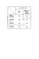
- FIG. 3 is a diagram illustrating on / off of the relay 13 according to the embodiment of the present invention.
- FIG. 4 is a diagram illustrating an energization state in the electric vehicle in each state of the power supply position.
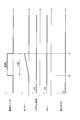
- FIG. 5 is a timing chart illustrating an operation example of the power supply control device 100 according to the embodiment of the present invention.
- FIG. 6 is a timing chart illustrating another operation example of the power supply control device 100 according to the embodiment of the present invention.
- FIG. 7 is a timing chart illustrating another operation example of the power supply control device 100 according to the embodiment of the present invention.
- FIG. 8 is a flowchart illustrating an operation example of the power supply control device 100 according to the embodiment of the present invention.
- the power supply control device 100 includes a controller 10, a power switch 11, a high-power battery 12, a relay 13, a DCDC converter 14, a light-power battery 15, and an electrical component 16.
- the vehicle in this embodiment is an electric vehicle that uses electricity as an energy source.
- the controller 10 is an electronic control unit (ECU) Electronic control unit (ECU) having a CPU (Central Processing Unit), a ROM (Read Only Memory), a RAM (Random Access Memory), a CAN (Control Area Network) communication circuit, and the like.
- the controller 10 controls each function of the electric vehicle. As an example, the controller 10 controls the on / off of the relay 13 based on the received signals (first signal to third signal).
- the power switch 11 is a pressing type switch installed in the vehicle.
- the installation location of the power switch 11 is not particularly limited, but it is usually installed at a position where the user sitting in the driver's seat can easily operate the power switch 11.
- the power switch 11 is installed near the steering wheel. Each time the user presses the power switch 11, the power state is switched. Such a state of the power supply is expressed as a "power supply position" in the present embodiment. The details of the power supply position will be described later.
- the power switch 11 is provided with an indicator indicating on / off.
- the high-power battery 12 is a drive battery mainly used as a power source for a motor (not shown).
- the high-power battery 12 is a large-capacity secondary battery composed of a plurality of battery modules.
- An external power source 30 is used to charge the high-power battery 12. The user charges the high-power battery 12 by connecting the external power supply 30 and the electric vehicle with a dedicated charging cable.
- the light battery 15 is used as a power source for the electrical component 16 mounted in the vehicle.
- the light electric battery 15 is, for example, a lead storage battery that stores electric power at a voltage of 12V to 15V.
- the electrical components 16 to which the light battery 15 supplies electric power are a navigation device, an audio device, and the like.
- a relay 13 and a DCDC converter 14 are connected between the high-power battery 12 and the low-power battery 15.
- the light battery 15 is electrically connected to the high battery 12 by the relay 13.
- the on / off of the relay 13 is controlled by the controller 10. When the power switch 11 is not off, the relay 13 is usually on.
- the DCDC converter 14 steps down the power of the high-power battery 12 to supply power to the low-power battery 15.
- the electrical component 16 and the DCDC converter 14 are shown separately in FIG. 1, the DCDC converter 14 is also a kind of the electrical component 16.
- the intelligence key 20 is used to remotely control the unlocking and locking of the door.
- the function of the intelligence key 20 is not limited to this.
- the door is unlocked even when the user presses the switch on the door handle or trunk.
- an antenna for transmitting radio waves and a receiver for receiving radio waves are provided to both the electric vehicle and the intelligence key 20.
- radio waves are transmitted from the antenna of the electric vehicle, and the intelligence ski 20 that receives the radio waves automatically returns the radio waves.
- the door is unlocked when the receiver of the electric vehicle receives this radio wave.
- the intelligence key 20 is sometimes called a smart key.
- the first signal shown in FIG. 1 is a signal transmitted from the power switch 11 to the controller 10.
- the second signal is a signal transmitted to the controller 10 when the external power supply 30 and the electric vehicle are connected by a dedicated charging cable.
- the third signal is a signal transmitted from the intelligence key 20 to the controller 10. When the controller 10 receives the first signal to the third signal, the controller 10 controls the on / off of the relay 13 according to the received signal.
- the power supply position includes four states of power off (first state), second state, third state, and fourth state. Further, the power supply position includes a fifth fifth state.
- first state the first state
- second state the second state
- third state the fourth state
- fourth state the power supply position
- fifth state the fifth state
- Power off is a state in which the power switch 11 is off.
- the power position is power off, only some devices operate. Some functions are door locks (including unlocks), communication devices, and security devices. Further, even when the power supply position is off, a minute current (so-called dark current) flows through the electrical component 16 for function backup and the like. This dark current is supplied from the light electric battery 15. When the power position is off, the indicator of the power switch 11 is off.
- the second state is the state in which the power switch 11 is on, and the indicator of the power switch 11 is lit.
- the relay 13 is on, and power is supplied from the high-power battery 12 to the low-power battery 15 via the relay 13. More specifically, when the power supply position is in the second state, power is supplied from the high-power battery 12 to the low-power battery 15 via the DCDC converter 14 by turning on the relay 13.
- the user can use many electrical components 16 except for a part. Specifically, in the second state, the user can operate the navigation device to set a route or operate the audio device to listen to the radio.
- the meter and blower motor do not operate. This is because the power supply position automatically shifts from the second state to the power off when a predetermined time (for example, about 1 to 10 minutes) elapses in the second state without any user operation.
- the blower motor is a motor for sending the air from the air conditioner into the passenger compartment, and is equipped with a fan. In this mechanism, if a predetermined time elapses without user operation, the blower motor stops and the air blower stops, that is, the air conditioner turns off. Users may be dissatisfied if the air conditioner is turned off automatically. Therefore, the blower motor does not operate in the second state.
- the meter is an electrical component that provides various information to the user, the user may find it inconvenient if the meter is automatically turned off. Therefore, the meter does not operate in the second state. No user operation means that there is no input from the user to the electrical component 16.
- the second state may be called AUTOACC.
- the third state is the state in which the power switch 11 is on as in the second state, and the indicator of the power switch 11 is lit.
- the relay 13 is on as in the second state, and power is supplied from the high-power battery 12 to the low-power battery 15 via the relay 13.
- the third state and the second state differ in the following points. That is, in the second state, the meter and the blower motor do not operate, whereas in the third state, all the electrical components including the meter and the blower motor operate.
- the third state may be called IGN-ON.
- the power position changes in the order of power off (first state), second state, and third state. If the user presses the power switch 11 while the power supply position is in the third state, the power supply position transitions to the second state.
- the power supply position is in the second state, as described above, if a predetermined time elapses without user operation, the power supply position automatically shifts to power off.
- the transition from the power off to the second state is not limited to the operation of the power switch 11.
- the power position also transitions from the power off to the second state when the user presses the unlock switch of the intelligence key 20.
- the third signal is transmitted from the intelligence key 20 to the controller 10 (see FIG. 1).
- the controller 10 shifts the power supply position from the power off to the second state.
- the user can use the navigation device, the audio device, etc. immediately after boarding.
- the time for which the electric power is supplied from the light electric battery 15 to the electrical component 16 becomes long, and the remaining capacity (SOC: START OF CHARGE) of the battery may decrease.
- the controller 10 turns on the relay 13 to supply electric power from the high-power battery 12 to the low-power battery 15 via the relay 13.
- the predetermined operation means an operation of pressing the power switch 11 while depressing the brake pedal. This operation can be performed regardless of whether the power supply position is the power off, the second state, or the third state.
- the power position changes from the power off, the second state, or the third state to the fourth state as shown in FIG.
- the electric vehicle can run in the fourth state.
- the power switch 11 is on, and the indicator of the power switch 11 is lit.
- the relay 13 is on, and power is supplied from the high-power battery 12 to the low-power battery 15 via the relay 13.
- all the electrical components including the meter and the blower motor operate as in the third state.
- the meter displays an icon indicating that the vehicle can run.
- the power position changes from the fourth state to the second state. This is because there is a need to use an audio device or the like even after the running is finished.
- the fourth state may be called READY-ON.
- the state in which power is supplied from the high-power battery 12 to the low-power battery 15 via the relay 13 may be referred to as a “high-power state”.
- the second state, the third state, and the fourth state shown in FIG. 2 are high electric power states.
- the table shown in FIG. 3 shows how the on / off of the relay 13 is controlled according to the power supply position.
- the relay 13 when the power supply position is power off, the relay 13 is normally off. When the power position is in the second state, the relay 13 is normally on. When the power position is in the third state, the relay 13 is normally on. When the power position is in the fourth state, the relay 13 is normally on.
- the controller 10 switches the relay 13 from on to off. More specifically, when the power switch 11 is pressed and held for a predetermined time or longer, a first signal (see FIG. 1) is transmitted from the power switch 11 to the controller 10. Upon receiving this first signal, the controller 10 switches the relay 13 from on to off. As a result, the light electric battery 15 is separated from the high electric battery 12, and the power supply from the high electric battery 12 is stopped. As a result, the high electric state is released.
- a predetermined time for example, 2 seconds
- One of the reasons for releasing the high power state when the power switch 11 is pressed and held for a predetermined time or longer in this way is to respond to an unexpected event. In the event of an unexpected event and rescue is required, a prompt release of the high power condition is required. Therefore, when the controller 10 of the present embodiment receives the first signal, the relay 13 is switched from on to off. Since the first signal is transmitted by pressing and holding the power switch 11 (for example, for 2 seconds or longer), according to the present embodiment, the high electric state can be easily and quickly released.
- the above-mentioned predetermined time is not limited to 2 seconds and can be changed as appropriate.
- the controller 10 switches the relay 13 from on to off when the power switch 11 is pressed and held for a predetermined time or longer, as in the case of the second state.
- the first signal is transmitted from the power switch 11 only when the power position is in the second or third state.
- the first signal is not transmitted from the power supply switch 11 even if the power switch 11 is pressed and held for a predetermined time or longer. Therefore, when the power supply position is the power off or the fourth state, the state of the relay 13 does not change as shown in FIG. 3 even if the power switch 11 is pressed and held for a predetermined time or longer.
- the release of the high power state is required for factory work, software update work for controllers mainly related to high power, etc.
- prompt release of the strong electric state is required.
- the high electric state can be released only by pressing and holding the power switch 11, so that the high electric state can be easily and quickly released. This makes the work in the factory, mainly the software update work in the controller related to high power, smooth.
- power is supplied from the light electric battery 15 to the electrical component 16 even in the state where the high electric power state is released (second state and third state).
- the table of FIG. 4 shows the energization status of the door lock, the communication device, the security device, the dark current, the electrical component 16, and the EV system as the energization status in the electric vehicle.
- the electrical component 16 is classified into a navigation device, an audio device, a meter, a blower motor, a power window, and a DCDC converter 14.
- EV systems are classified into heaters, compressors, and inverters. The heater is used to heat the high-power battery 12.
- Power is supplied from the light battery 15 to the navigation device, audio device, meter, blower motor, power window, and DCDC converter 14. Electric power is supplied to the heater, compressor, and inverter from the high-power battery 12.
- the power supply position is classified into power off (first state), second state, third state, fourth state, and fifth state.
- the power off, the second state, the third state, and the fourth state have already been described.
- the fifth state is a state in which the power switch 11 is pressed and held for a predetermined time or longer when the power supply position is in the second state or the third state.
- the power supply position when the power supply position is in the second state, power is supplied from the light electric battery 15 to the navigation device, the audio device, the power window, and the DCDC converter 14. Further, when the power supply position is in the second state, since it is in the high electric power state as described above, the heater, the compressor, and the inverter are supplied with electric power from the high electric power battery 12.
- the power supply position when the power supply position is in the second state, power is not supplied from the light battery 15 to the meter and the blower motor.
- the second state has a mechanism (so-called time limit) for automatically transitioning to the power off under a predetermined condition.
- the user may be dissatisfied if the air conditioner is automatically turned off. Since the meter is an electrical component that provides various information to the user, the user may find it inconvenient if the meter is automatically turned off. Therefore, in the second state, power is not supplied from the light battery 15 to the meter and the blower motor.
- the third state When the power supply position is in the third state, power is supplied to all the devices shown in FIG. Unlike the second state, the third state has no time limit. That is, even if a predetermined time elapses without any user operation in the third state, the power supply position does not automatically transition to power off.
- the high electric power state is released as described above, so that the heater, the compressor, and the inverter are not supplied with electric power from the high electric power battery 12.
- the transition from the 3rd state to the 5th state is supplemented.
- the power supply position when the power supply position is in the third state, the power supply position transitions to the fifth state when the power supply switch 11 is pressed and held for a predetermined time or longer.
- the power supply position first transitions to the second state, and when the power supply switch 11 is pressed and held for a predetermined time or longer, the power supply position transitions to the fifth state.
- the strong electric state can be released by the same operation (holding down the power switch 11). It is possible to prevent the operation from becoming complicated as compared with the case of making the switch.
- the initial state (time: 0) in FIG. 5 indicates the second state. That is, the timing chart shown in FIG. 5 starts from the scene where the controller 10 receives the third signal (see FIG. 1) and shifts the power supply position from the power off to the second state.
- the system requirement is on.
- the system request is on, it means the request in the high power state.
- the controller 10 turns on the relay 13 to supply power from the high-power battery 12 to the low-power battery 15 via the relay 13.
- the power switch 11 is pressed and held at time T1 in FIG.
- a person who presses and holds the power switch 11 for a long time is assumed to be a user of an electric vehicle, a rescue worker, a factory worker, a dealer, or the like.
- a timer one of the functions of the controller 10) is activated to measure the time when the power switch 11 is pressed and held for a long time.
- time T2 When the time that the power switch 11 is held down exceeds the threshold value (time T2), the controller 10 switches the relay 13 from on to off. As a result, the light electric battery 15 is separated from the high electric battery 12, and the power supply from the high electric battery 12 is stopped. As a result, the high electric state is released. At time T2, the power supply position transitions from the second state to the fifth state.
- the threshold value here has the same meaning as the above-mentioned predetermined time.
- the prohibition flag is a flag used to prohibit the controller 10 from switching the relay 13 from off to on.
- the prohibition flag is set to 0, the controller 10 can switch the relay 13 from off to on.
- the prohibition flag is set to 1, the controller 10 cannot switch the relay 13 from off to on.
- the controller 10 switches the relay 13 from on to off when the power switch 11 is pressed and held for a predetermined time or longer in order to quickly release the high electric state.
- the controller 10 switches the relay 13 from off to on again.
- the state shifts to the high electric state again. Therefore, it is necessary to prevent the transition to the high electric state again after the high electric state is released.
- the prohibition flag is switched from 0 to 1 when the power switch 11 is pressed and held for a predetermined time or longer.
- the controller 10 when the power switch 11 is held down for less than the threshold value (1.5 seconds), the controller 10 does not switch the relay 13 from on to off. Further, the controller 10 does not switch the prohibition flag from 0 to 1.
- the initial state (time: 0) in FIG. 7 shows the state after the prohibition flag is switched from 0 to 1. That is, the timing chart shown in FIG. 7 starts from the state after the time T2 in FIG.
- the high electric state is released, and the power supply position is the fifth state.
- the system requirement remains on because the electrical component 16 operates even when the power position is in the fifth state.
- the controller 10 switches the prohibition flag from 1 to 0 and switches the relay 13 from off to on.
- the controller 10 releases the high power state and prevents the transition to the high power state again. If the cause (rescue, factory work, software update work, etc.) that caused the high power state to be released is resolved, it may be necessary to return to the high power state again depending on the situation.
- the case of charging the high-power battery 12 or the case of running an electric vehicle For example, the case of charging the high-power battery 12 or the case of running an electric vehicle.
- the high-power battery 12 it is necessary to return to the high-power state in order to charge the low-power battery 15 at the same time.
- the electric vehicle When the electric vehicle is driven, it is necessary to return to the high electric state in order to prevent the SOC of the low electric battery 15 from deteriorating.
- Other requirements at time T3 in FIG. 7 include a request for charging the high-power battery 12 and a request for running an electric vehicle.
- the other request is turned on when a second signal (see FIG. 1) indicating that the high-power battery 12 has started charging is transmitted to the controller 10, or when the power switch 11 is pressed while depressing the brake pedal. This means that the indicated signal is transmitted to the controller 10.
- Other requirements are different from system requirements.
- Another requirement may be a requirement for controlling an air conditioner mounted on an electric vehicle.
- the other request is turned on means that a signal for controlling the air conditioner is transmitted to the controller 10.
- the signal for controlling the air conditioner may be a signal for the user to operate the smartphone to control the air conditioner (remote control or timer control), or may be a signal for heating or cooling the high-power battery 12.
- the controller 10 switches the prohibition flag from 1 to 0, and the relay 13 is switched from off to on. As a result, even after the high electric state is released and the transition to the high electric state is prevented, it is possible to return to the high electric state again.
- step S101 when the user presses the unlock switch of the intelligence key 20, a third signal is transmitted from the intelligence key 20 to the controller 10 (see FIG. 1).
- step S103 the controller 10 that has received the third signal shifts the power supply position from the power supply off (first state) to the second state (see FIG. 2).
- the relay 13 In the second state, the relay 13 is on, and power is supplied from the high-power battery 12 to the low-power battery 15 via the relay 13.
- step S105 When the power switch 11 is pressed and held for a predetermined time or longer (YES in step S105), the process proceeds to step S107, and the controller 10 switches the relay 13 from on to off. As a result, the light electric battery 15 is separated from the high electric battery 12, and the power supply from the high electric battery 12 is stopped. As a result, the high electric state is released. Further, the controller 10 switches the prohibition flag from 0 to 1 (step S109). This prevents the relay 13 from switching from off to on, and prevents the relay 13 from transitioning to the high electric state again. If NO in step S105, the process waits.
- step S109 when the user connects the external power supply 30 and the electric vehicle with a dedicated charging cable and starts charging the high-power battery 12, a second signal indicating the start of charging of the high-power battery 12 is sent to the controller 10. Will be sent.
- the controller 10 receives this second signal (YES in step S111)
- the process proceeds to step S113, and the controller 10 switches the prohibition flag from 1 to 0. This allows the controller 10 to switch the relay 13 from off to on.
- step S115 the controller 10 switches the relay 13 from off to on.
- step S103 the case where the power supply position transitions to the second state has been described in step S103, but the same applies to the case where the power supply position transitions to the third state.
- the controller 10 When the controller 10 receives the first signal (see FIG. 1) when the power position is in the second or third state, the controller 10 switches the relay 13 from on to off, and then the relay 13 turns from off to on. It is prohibited to switch to. As a result, even if the user presses the unlock switch of the intelligence key 20 again after the high electric state is released, the transition to the high electric state is prevented.
- the controller 10 When the controller 10 receives the second signal (see FIG. 1) after prohibiting the relay 13 from switching from off to on, the controller 10 switches the relay 13 from off to on. As a result, even after the high electric state is released and the transition to the high electric state is prevented, it is possible to return to the high electric state again.
- the second signal is a signal for enabling the electric vehicle to run, a signal for indicating the start of charging of the high-power battery 12, a signal for controlling an air conditioner mounted on the electric vehicle, or a decrease in the remaining capacity of the low-power battery 15. Includes at least one of the signals to prevent.
- the controller 10 When the controller 10 receives the third signal from the intelligence key 20, the controller 10 shifts the power supply position from the power off to the second state. In other words, when the controller 10 receives the third signal from the intelligence key 20, power is supplied from the high-power battery 12 to the low-power battery 15 via the relay 13 from the power-off state (not the high-power state). Transition to the state to be performed (high power state). That is, in the present embodiment, the state that is not the high electric state is easily changed to the high electric state. Therefore, when the controller 10 switches the relay 13 from on to off by pressing and holding the power switch 11, the controller 10 sets a prohibition flag so that the relay 13 does not switch from off to on again even if the third signal is subsequently received. do. As a result, even if the user presses the unlock switch of the intelligence key 20 again after the high electric state is released, the transition to the high electric state is prevented.
- the processing circuit includes a programmed processing device such as a processing device including an electric circuit.
- Processing circuits also include devices such as application specific integrated circuits (ASICs) and circuit components arranged to perform the described functions.
- ASICs application specific integrated circuits
Landscapes
- Engineering & Computer Science (AREA)
- Power Engineering (AREA)
- Transportation (AREA)
- Mechanical Engineering (AREA)
- Life Sciences & Earth Sciences (AREA)
- Sustainable Development (AREA)
- Sustainable Energy (AREA)
- Charge And Discharge Circuits For Batteries Or The Like (AREA)
- Electric Propulsion And Braking For Vehicles (AREA)
- Direct Current Feeding And Distribution (AREA)
- Relay Circuits (AREA)
Abstract
Description
以上説明したように、本実施形態に係る電源制御装置100によれば、以下の作用効果が得られる。 (Action effect)
As described above, according to the power
10 コントローラ
11 電源スイッチ
12 強電バッテリ
13 リレー
14 DCDCコンバータ
15 弱電バッテリ
16 電装品
20 インテリジェンスキー
30 外部電源 100
Claims (7)
- 強電バッテリと、弱電バッテリと、前記強電バッテリ及び前記弱電バッテリを電気的に接続するリレーと、電源スイッチと、前記リレーのオンオフを制御するコントローラとを備える電源制御装置の電源制御方法であって、
電源の状態が前記強電バッテリから前記弱電バッテリに前記リレーを介して電力が供給されている状態である場合において、前記コントローラは第1信号を受信したとき、前記リレーをオンからオフに切り替え、その後、前記リレーがオフからオンに切り替わることを禁止する
ことを特徴とする電源制御方法。 A power control method for a power control device including a high-power battery, a low-power battery, a relay for electrically connecting the high-power battery and the low-power battery, a power switch, and a controller for controlling on / off of the relay.
When the power supply state is a state in which power is supplied from the high-power battery to the low-power battery via the relay, the controller switches the relay from on to off when the first signal is received, and then switches the relay from on to off. , A power control method comprising prohibiting the relay from being switched from off to on. - 前記コントローラが前記第1信号を受信し、前記リレーをオンからオフに切り替えた状態において、前記弱電バッテリから車両に搭載された電装品へ電力が供給される
ことを特徴とする請求項1に記載の電源制御方法。 The first aspect of claim 1, wherein power is supplied from the light electric battery to the electrical components mounted on the vehicle in a state where the controller receives the first signal and switches the relay from on to off. Power control method. - 前記第1信号は、前記電源スイッチが所定時間以上長押しされたことを示す信号である
ことを特徴とする請求項1または2に記載の電源制御方法。 The power supply control method according to claim 1 or 2, wherein the first signal is a signal indicating that the power supply switch has been pressed and held for a predetermined time or longer. - 前記コントローラは、前記リレーがオフからオンに切り替わることを禁止した後に第2信号を受信した場合、前記リレーをオフからオンに切り替える
ことを特徴とする請求項1に記載の電源制御方法。 The power supply control method according to claim 1, wherein the controller switches the relay from off to on when the second signal is received after prohibiting the relay from switching from off to on. - 前記第2信号は、車両を走行可能状態にするための信号、前記強電バッテリの充電開始を示す信号、前記車両に搭載された空調装置を制御するための信号、あるいは前記弱電バッテリの残容量低下を防止するための信号のうち、少なくとも一つを含む
ことを特徴とする請求項4に記載の電源制御方法。 The second signal is a signal for enabling the vehicle to run, a signal for indicating the start of charging of the high-power battery, a signal for controlling an air conditioner mounted on the vehicle, or a decrease in the remaining capacity of the low-power battery. The power supply control method according to claim 4, further comprising at least one of the signals for preventing the above. - 前記電源の状態は、
前記電源がオフである第1状態と、
前記強電バッテリから前記弱電バッテリに前記リレーを介して電力が供給される第2状態と、を含み、
前記コントローラは、ユーザが車両に乗り込む前に前記ユーザが所持するキーから発信される第3信号を受信した場合、前記電源の状態を前記第1状態から前記第2状態に遷移させる
ことを特徴とする請求項1~5のいずれか1項に記載の電源制御方法。 The state of the power supply is
The first state in which the power is off and
A second state in which power is supplied from the high-power battery to the low-power battery via the relay, and the like.
The controller is characterized in that when a third signal transmitted from a key possessed by the user is received before the user gets into the vehicle, the state of the power supply is changed from the first state to the second state. The power supply control method according to any one of claims 1 to 5. - 強電バッテリと、弱電バッテリと、前記強電バッテリ及び前記弱電バッテリを電気的に接続するリレーと、電源スイッチと、前記リレーのオンオフを制御するコントローラとを備える電源制御装置であって、
電源の状態が前記強電バッテリから前記弱電バッテリに前記リレーを介して電力が供給されている状態である場合において、前記コントローラは第1信号を受信したとき、前記リレーをオンからオフに切り替え、その後、前記リレーがオフからオンに切り替わることを禁止する
ことを特徴とする電源制御装置。 A power control device including a high-power battery, a low-power battery, a relay for electrically connecting the high-power battery and the low-power battery, a power switch, and a controller for controlling on / off of the relay.
When the state of the power supply is a state in which power is supplied from the high-power battery to the low-power battery via the relay, the controller switches the relay from on to off when the first signal is received, and then switches the relay from on to off. , A power control device comprising prohibiting the relay from being switched from off to on.
Priority Applications (7)
| Application Number | Priority Date | Filing Date | Title |
|---|---|---|---|
| PCT/JP2020/017955 WO2021220340A1 (en) | 2020-04-27 | 2020-04-27 | Power supply control method and power supply control device |
| JP2022518438A JP7447996B2 (en) | 2020-04-27 | 2020-04-27 | Power control method and power control device |
| BR112022021672A BR112022021672A2 (en) | 2020-04-27 | 2020-04-27 | ENERGY SUPPLY CONTROL METHOD AND ENERGY SUPPLY CONTROL DEVICE |
| EP20934104.9A EP4144561A4 (en) | 2020-04-27 | 2020-04-27 | Power supply control method and power supply control device |
| CN202080100266.7A CN115461243A (en) | 2020-04-27 | 2020-04-27 | Power supply control method and power supply control device |
| MX2022013368A MX2022013368A (en) | 2020-04-27 | 2020-04-27 | Power supply control method and power supply control device. |
| US17/920,671 US20230150366A1 (en) | 2020-04-27 | 2020-04-27 | Power Supply Control Method and Power Supply Control Device |
Applications Claiming Priority (1)
| Application Number | Priority Date | Filing Date | Title |
|---|---|---|---|
| PCT/JP2020/017955 WO2021220340A1 (en) | 2020-04-27 | 2020-04-27 | Power supply control method and power supply control device |
Publications (1)
| Publication Number | Publication Date |
|---|---|
| WO2021220340A1 true WO2021220340A1 (en) | 2021-11-04 |
Family
ID=78373412
Family Applications (1)
| Application Number | Title | Priority Date | Filing Date |
|---|---|---|---|
| PCT/JP2020/017955 WO2021220340A1 (en) | 2020-04-27 | 2020-04-27 | Power supply control method and power supply control device |
Country Status (7)
| Country | Link |
|---|---|
| US (1) | US20230150366A1 (en) |
| EP (1) | EP4144561A4 (en) |
| JP (1) | JP7447996B2 (en) |
| CN (1) | CN115461243A (en) |
| BR (1) | BR112022021672A2 (en) |
| MX (1) | MX2022013368A (en) |
| WO (1) | WO2021220340A1 (en) |
Cited By (2)
| Publication number | Priority date | Publication date | Assignee | Title |
|---|---|---|---|---|
| WO2023188139A1 (en) * | 2022-03-30 | 2023-10-05 | 三菱自動車工業株式会社 | Power source management device for electric vehicle |
| WO2023188133A1 (en) * | 2022-03-30 | 2023-10-05 | 三菱自動車工業株式会社 | Power supply management device for electric vehicle |
Citations (5)
| Publication number | Priority date | Publication date | Assignee | Title |
|---|---|---|---|---|
| JP2005051885A (en) * | 2003-07-31 | 2005-02-24 | Toyota Motor Corp | Power supply controller, and power output unit and automobile equipped with same |
| JP2005261041A (en) * | 2004-03-10 | 2005-09-22 | Toyota Motor Corp | Driving system and automobile mounted with the same |
| JP2015107022A (en) * | 2013-12-02 | 2015-06-08 | トヨタ自動車株式会社 | Charging/discharging control device of vehicle |
| JP2018083486A (en) * | 2016-11-22 | 2018-05-31 | 株式会社デンソー | Vehicle control device |
| JP2018098844A (en) | 2016-12-09 | 2018-06-21 | 三菱自動車工業株式会社 | Power source control device |
Family Cites Families (2)
| Publication number | Priority date | Publication date | Assignee | Title |
|---|---|---|---|---|
| DE102012015059A1 (en) * | 2012-07-28 | 2014-05-15 | Volkswagen Aktiengesellschaft | Method for deactivating a high voltage system of a motor vehicle |
| US10086705B2 (en) * | 2016-06-28 | 2018-10-02 | Toyota Motor Engineering & Manufacturing North America, Inc. | Multipoint emergency responder safety isolation system |
-
2020
- 2020-04-27 EP EP20934104.9A patent/EP4144561A4/en active Pending
- 2020-04-27 BR BR112022021672A patent/BR112022021672A2/en unknown
- 2020-04-27 JP JP2022518438A patent/JP7447996B2/en active Active
- 2020-04-27 US US17/920,671 patent/US20230150366A1/en active Pending
- 2020-04-27 MX MX2022013368A patent/MX2022013368A/en unknown
- 2020-04-27 CN CN202080100266.7A patent/CN115461243A/en active Pending
- 2020-04-27 WO PCT/JP2020/017955 patent/WO2021220340A1/en unknown
Patent Citations (5)
| Publication number | Priority date | Publication date | Assignee | Title |
|---|---|---|---|---|
| JP2005051885A (en) * | 2003-07-31 | 2005-02-24 | Toyota Motor Corp | Power supply controller, and power output unit and automobile equipped with same |
| JP2005261041A (en) * | 2004-03-10 | 2005-09-22 | Toyota Motor Corp | Driving system and automobile mounted with the same |
| JP2015107022A (en) * | 2013-12-02 | 2015-06-08 | トヨタ自動車株式会社 | Charging/discharging control device of vehicle |
| JP2018083486A (en) * | 2016-11-22 | 2018-05-31 | 株式会社デンソー | Vehicle control device |
| JP2018098844A (en) | 2016-12-09 | 2018-06-21 | 三菱自動車工業株式会社 | Power source control device |
Non-Patent Citations (1)
| Title |
|---|
| See also references of EP4144561A4 |
Cited By (2)
| Publication number | Priority date | Publication date | Assignee | Title |
|---|---|---|---|---|
| WO2023188139A1 (en) * | 2022-03-30 | 2023-10-05 | 三菱自動車工業株式会社 | Power source management device for electric vehicle |
| WO2023188133A1 (en) * | 2022-03-30 | 2023-10-05 | 三菱自動車工業株式会社 | Power supply management device for electric vehicle |
Also Published As
| Publication number | Publication date |
|---|---|
| EP4144561A1 (en) | 2023-03-08 |
| CN115461243A (en) | 2022-12-09 |
| JPWO2021220340A1 (en) | 2021-11-04 |
| JP7447996B2 (en) | 2024-03-12 |
| US20230150366A1 (en) | 2023-05-18 |
| EP4144561A4 (en) | 2023-06-14 |
| BR112022021672A2 (en) | 2022-12-20 |
| MX2022013368A (en) | 2022-11-30 |
Similar Documents
| Publication | Publication Date | Title |
|---|---|---|
| CN107323265B (en) | Power-on and power-off control method and system for hybrid electric vehicle | |
| JP6710581B2 (en) | Vehicle battery over-discharge prevention device and method | |
| JP3549806B2 (en) | Automotive power supply controller | |
| JP5720707B2 (en) | Communication system and communication node | |
| US20100244560A1 (en) | Vehicle power supply system | |
| WO2021220340A1 (en) | Power supply control method and power supply control device | |
| JP2008006946A (en) | Power source control device for vehicle | |
| CN110481501A (en) | Starting method, system and the electronic equipment of electric vehicle | |
| CN112383558B (en) | Vehicle air conditioner remote control method, vehicle and computer readable storage medium | |
| WO2024001635A1 (en) | Power source management system, vehicle and power source management method | |
| CN107351789B (en) | Control method for low-voltage power on and power off of whole vehicle, whole vehicle controller and vehicle | |
| US11608028B1 (en) | Systems and methods for multi-zoned vehicle wake up | |
| JP2010076509A (en) | Power supply monitoring device | |
| US11858378B2 (en) | Battery discharge control system including a battery saver for motor-driven vehicle and battery discharge control method using the battery saver for motor-driven vehicle | |
| CN113085654A (en) | Automatic power shortage prevention control method and system for low-voltage battery of electric vehicle | |
| CN111717145B (en) | Multi-path vehicle power supply switching method and device | |
| JP3167419B2 (en) | Automotive battery monitoring device | |
| CN112112958B (en) | Vehicle power-on and power-off control method, vehicle and computer-readable storage medium | |
| KR101823903B1 (en) | Background Current Prevent System for Enhancing Re-Starting Performance of Vehicle | |
| JPH0746701A (en) | Air conditioner for electric automobile | |
| CN111717144B (en) | Vehicle power supply management method and device with starting switch being cancelled | |
| JP2012205469A (en) | Power supply device, power control device, and power supply program | |
| JP4539114B2 (en) | Drive system and automobile equipped with the same | |
| CN110588467A (en) | Automatic heating control method for automobile seat | |
| JP2012029432A (en) | Power supply device |
Legal Events
| Date | Code | Title | Description |
|---|---|---|---|
| 121 | Ep: the epo has been informed by wipo that ep was designated in this application |
Ref document number: 20934104 Country of ref document: EP Kind code of ref document: A1 |
|
| ENP | Entry into the national phase |
Ref document number: 2022518438 Country of ref document: JP Kind code of ref document: A |
|
| REG | Reference to national code |
Ref country code: BR Ref legal event code: B01A Ref document number: 112022021672 Country of ref document: BR |
|
| NENP | Non-entry into the national phase |
Ref country code: DE |
|
| ENP | Entry into the national phase |
Ref document number: 2020934104 Country of ref document: EP Effective date: 20221128 |
|
| ENP | Entry into the national phase |
Ref document number: 112022021672 Country of ref document: BR Kind code of ref document: A2 Effective date: 20221025 |