WO2021215363A1 - ボールジョイント及びダストカバー - Google Patents
ボールジョイント及びダストカバー Download PDFInfo
- Publication number
- WO2021215363A1 WO2021215363A1 PCT/JP2021/015737 JP2021015737W WO2021215363A1 WO 2021215363 A1 WO2021215363 A1 WO 2021215363A1 JP 2021015737 W JP2021015737 W JP 2021015737W WO 2021215363 A1 WO2021215363 A1 WO 2021215363A1
- Authority
- WO
- WIPO (PCT)
- Prior art keywords
- socket
- reinforcing ring
- body portion
- dust cover
- elastic body
- Prior art date
- Legal status (The legal status is an assumption and is not a legal conclusion. Google has not performed a legal analysis and makes no representation as to the accuracy of the status listed.)
- Ceased
Links
Images


Classifications
-
- F—MECHANICAL ENGINEERING; LIGHTING; HEATING; WEAPONS; BLASTING
- F16—ENGINEERING ELEMENTS AND UNITS; GENERAL MEASURES FOR PRODUCING AND MAINTAINING EFFECTIVE FUNCTIONING OF MACHINES OR INSTALLATIONS; THERMAL INSULATION IN GENERAL
- F16J—PISTONS; CYLINDERS; SEALINGS
- F16J15/00—Sealings
- F16J15/50—Sealings between relatively-movable members, by means of a sealing without relatively-moving surfaces, e.g. fluid-tight sealings for transmitting motion through a wall
- F16J15/52—Sealings between relatively-movable members, by means of a sealing without relatively-moving surfaces, e.g. fluid-tight sealings for transmitting motion through a wall by means of sealing bellows or diaphragms
- F16J15/525—Sealings between relatively-movable members, by means of a sealing without relatively-moving surfaces, e.g. fluid-tight sealings for transmitting motion through a wall by means of sealing bellows or diaphragms fixed to a part of a transmission performing a wobbling or a circular translatory movement
-
- F—MECHANICAL ENGINEERING; LIGHTING; HEATING; WEAPONS; BLASTING
- F16—ENGINEERING ELEMENTS AND UNITS; GENERAL MEASURES FOR PRODUCING AND MAINTAINING EFFECTIVE FUNCTIONING OF MACHINES OR INSTALLATIONS; THERMAL INSULATION IN GENERAL
- F16C—SHAFTS; FLEXIBLE SHAFTS; ELEMENTS OR CRANKSHAFT MECHANISMS; ROTARY BODIES OTHER THAN GEARING ELEMENTS; BEARINGS
- F16C11/00—Pivots; Pivotal connections
- F16C11/04—Pivotal connections
- F16C11/06—Ball-joints; Other joints having more than one degree of angular freedom, i.e. universal joints
- F16C11/0666—Sealing means between the socket and the inner member shaft
-
- F—MECHANICAL ENGINEERING; LIGHTING; HEATING; WEAPONS; BLASTING
- F16—ENGINEERING ELEMENTS AND UNITS; GENERAL MEASURES FOR PRODUCING AND MAINTAINING EFFECTIVE FUNCTIONING OF MACHINES OR INSTALLATIONS; THERMAL INSULATION IN GENERAL
- F16C—SHAFTS; FLEXIBLE SHAFTS; ELEMENTS OR CRANKSHAFT MECHANISMS; ROTARY BODIES OTHER THAN GEARING ELEMENTS; BEARINGS
- F16C11/00—Pivots; Pivotal connections
- F16C11/04—Pivotal connections
- F16C11/06—Ball-joints; Other joints having more than one degree of angular freedom, i.e. universal joints
- F16C11/0614—Ball-joints; Other joints having more than one degree of angular freedom, i.e. universal joints the female part of the joint being open on two sides
-
- F—MECHANICAL ENGINEERING; LIGHTING; HEATING; WEAPONS; BLASTING
- F16—ENGINEERING ELEMENTS AND UNITS; GENERAL MEASURES FOR PRODUCING AND MAINTAINING EFFECTIVE FUNCTIONING OF MACHINES OR INSTALLATIONS; THERMAL INSULATION IN GENERAL
- F16C—SHAFTS; FLEXIBLE SHAFTS; ELEMENTS OR CRANKSHAFT MECHANISMS; ROTARY BODIES OTHER THAN GEARING ELEMENTS; BEARINGS
- F16C11/00—Pivots; Pivotal connections
- F16C11/04—Pivotal connections
- F16C11/06—Ball-joints; Other joints having more than one degree of angular freedom, i.e. universal joints
- F16C11/0666—Sealing means between the socket and the inner member shaft
- F16C11/0671—Sealing means between the socket and the inner member shaft allowing operative relative movement of joint parts due to flexing of the sealing means
-
- F—MECHANICAL ENGINEERING; LIGHTING; HEATING; WEAPONS; BLASTING
- F16—ENGINEERING ELEMENTS AND UNITS; GENERAL MEASURES FOR PRODUCING AND MAINTAINING EFFECTIVE FUNCTIONING OF MACHINES OR INSTALLATIONS; THERMAL INSULATION IN GENERAL
- F16J—PISTONS; CYLINDERS; SEALINGS
- F16J3/00—Diaphragms; Bellows; Bellows pistons
- F16J3/04—Bellows
- F16J3/041—Non-metallic bellows
- F16J3/042—Fastening details
-
- F—MECHANICAL ENGINEERING; LIGHTING; HEATING; WEAPONS; BLASTING
- F16—ENGINEERING ELEMENTS AND UNITS; GENERAL MEASURES FOR PRODUCING AND MAINTAINING EFFECTIVE FUNCTIONING OF MACHINES OR INSTALLATIONS; THERMAL INSULATION IN GENERAL
- F16J—PISTONS; CYLINDERS; SEALINGS
- F16J15/00—Sealings
- F16J15/50—Sealings between relatively-movable members, by means of a sealing without relatively-moving surfaces, e.g. fluid-tight sealings for transmitting motion through a wall
- F16J15/52—Sealings between relatively-movable members, by means of a sealing without relatively-moving surfaces, e.g. fluid-tight sealings for transmitting motion through a wall by means of sealing bellows or diaphragms
Definitions
- the present invention relates to a ball joint and a dust cover provided in a vehicle or the like.
- a dust cover has been used to prevent water and dust from entering the joint portion and to prevent grease from flowing out from the joint portion.
- the ball stud is configured to be rotatable and swingable with respect to the socket, and the sealing portion of the dust cover maintains the sealing property while following the rotating and swinging ball stud.
- the sealing portion of the dust cover maintains the sealing property while following the rotating and swinging ball stud.
- An object of the present invention is to provide a ball joint and a dust cover that can suppress an adverse effect on the seal portion even when the ball stud swings greatly.
- the present invention has adopted the following means to solve the above problems.
- the ball joint of the present invention A ball stud having a spherical portion at one end of a shaft portion, a socket having a bearing of the spherical portion and supporting the ball stud in a rotatable and swingable manner, and a socket on the shaft portion opposite to the spherical portion are coupled.
- the dust cover attached to the ball joint body and It is a ball joint equipped with The dust cover is Deformable fuselage and A fixed portion provided on one end side of the body portion and fixed to the socket, and a fixed portion.
- a seal portion provided on the other end side of the body portion and With The seal portion is An elastic body portion provided integrally with the body portion and having an inner peripheral sealing portion that slides on the outer peripheral surface of the shaft portion. It has a reinforcing ring embedded in the elastic body portion, and has. At least a part of the tip surface of the reinforcing ring on the connecting member side is exposed from the elastic body portion and is in contact with the connecting member.
- the dust cover of the present invention A ball stud having a spherical portion at one end of a shaft portion, a socket having a bearing of the spherical portion and supporting the ball stud in a rotatable and swingable manner, and a socket on the shaft portion opposite to the spherical portion are coupled. It is a dust cover attached to a ball joint body having a coupling member to be formed. Deformable fuselage and A fixed portion provided on one end side of the body portion and fixed to the socket, and a fixed portion. A seal portion provided on the other end side of the body portion and With The seal portion is An elastic body portion provided integrally with the body portion and having an inner peripheral sealing portion that slides on the outer peripheral surface of the shaft portion. It has a reinforcing ring embedded in the elastic body portion, and has. At least a part of the tip surface of the reinforcing ring on the side of the connecting member is configured to be exposed from the elastic body portion and in contact with the connecting member.
- the positional relationship between the reinforcing ring and the connecting member is maintained regardless of the operation of the ball stud, so that a part of the elastic body portion is sandwiched between the reinforcing ring and the connecting member. Can be suppressed.
- the tip surface of the reinforcing ring on the connecting member side is exposed over the entire circumference and is in contact with the connecting member, and is located on the inner peripheral surface side of the portion where the reinforcing ring is in contact with the connecting member. It is preferable that the inner peripheral seal portion is provided.
- At least a part of the socket-side tip surface of the reinforcing ring is exposed from the elastic body portion, and when the ball stud swings with respect to the socket, the socket-side tip of the reinforcing ring It is preferable that the exposed portion of the surface abuts on the socket to regulate the swing range of the ball stud.
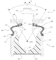
- FIG. 1 is a schematic cross-sectional view of a ball joint according to an embodiment of the present invention.
- FIG. 2 is a partially cutaway cross-sectional view of the dust cover according to the embodiment of the present invention.
- FIG. 3 is a schematic view of a reinforcing ring according to an embodiment of the present invention.
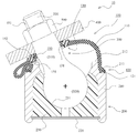
- FIG. 4 is a schematic cross-sectional view of the ball joint according to the embodiment of the present invention.
- Example 2 The ball joint and the dust cover according to the embodiment of the present invention will be described with reference to FIGS. 1 to 4.
- the ball joint according to this embodiment is provided in various devices such as vehicles.
- FIGS. 1 and 4 are schematic cross-sectional views of a ball joint according to an embodiment of the present invention.
- FIG. 1 and FIG. 4 a cross-sectional view in which a dust cover or the like is cut at a surface including a central axis of a shaft portion of a ball stud provided in a ball joint is shown.
- FIG. 1 shows a state in which the ball stud is straight
- FIG. 4 shows a state in which the ball stud swings to the maximum.
- the ball joint 10 includes a ball joint main body and a dust cover 100 attached to the ball joint main body.
- the ball joint body includes a ball stud 300, a socket 200 that rotatably and swingably supports the ball stud 300, and a knuckle 400 as a connecting member that connects to the shaft portion 310 of the ball stud 300.
- the ball stud 300 has a spherical portion 320 at one end of the shaft portion 310.
- the socket 200 includes an annular case 210, a bottom plate 220 fixed to the bottom side of the case 210, and a bearing 230 of the spherical portion 320.
- the bearing 230 has a bearing surface 231 formed of a spherical surface having the same diameter as the radius of curvature of the spherical portion 320.
- the knuckle 400 is connected to the shaft portion 310 by a nut 500 on the side of the shaft portion 310 opposite to the spherical portion 320.
- a screw portion 331 is provided on the outer peripheral surface of the tip 330 of the shaft portion 310, and the nut 500 is screwed to the screw portion 331.
- the ball stud 300 can rotate (see arrow Q in FIG. 1) and swing (see arrow P in FIG. 1) with respect to the socket 200. can.
- the ball joint 10 according to the present embodiment is provided with a dust cover 100 in order to prevent water, dust, etc. from entering the joint portion and to prevent grease from flowing out from the joint portion.
- FIG. 2 is a partially cutaway sectional view of the dust cover 100 according to the embodiment of the present invention.
- FIG. 2 shows a state in which no external force acts on the dust cover 100. Further, in a state where no external force acts on the dust cover 100, the dust cover 100 has a substantially rotationally symmetric shape.
- FIG. 2 a cross-sectional view of the dust cover 100 cut along a surface including the central axis of the dust cover 100 in a state where no external force is applied to the dust cover 100 is shown on the left side of the drawing.
- FIG. 3 is a schematic view of a reinforcing ring according to an embodiment of the present invention.
- FIG. 3A is a bottom view of the reinforcing ring
- FIG. 3B is a cross-sectional view taken along the line AA in FIG. 3A.
- the dust cover 100 has a deformable film-like body portion 110, a fixed portion 120 provided on one end side of the body portion 110 and fixed to the socket 200, and a seal portion provided on the other end side of the body portion 110. It is equipped with 130.
- the body portion 110 is configured so that the center bulges outward.
- Most of the dust cover 100 is made of an elastic body such as rubber. More specifically, it is made of an elastic body except for the reinforcing rings 121 and 150 embedded in the fixed portion 120 and the seal portion 130, respectively. That is, the body portion 110, the fixed portion 120, and the seal portion 130 are integrally provided except for the reinforcing rings 121 and 150.
- the reinforcing ring 121 is made of a highly rigid material such as metal.
- the seal portion 130 is provided with an elastic body portion provided integrally with the body portion 110 and the like.
- the inner peripheral surface of the elastic body portion is composed of an inner peripheral sealing portion 131 that slides on the outer peripheral surface of the shaft portion 310 of the ball stud 300.
- the inner peripheral seal portion 131 according to this embodiment is composed of a plurality of annular protrusions.
- the reinforcing ring 150 is embedded in the elastic body portion of the seal portion 130.
- the reinforcing ring 150 is composed of an annular member.
- the reinforcing ring 150 is made of a material having a higher rigidity than the elastic body portion, such as nylon resin.
- a plurality of columnar protrusions 151 are provided on the bottom surface side of the reinforcing ring 150. In this embodiment, a configuration in which a plurality of protrusions 151 are provided at equal intervals is adopted, but it is not always necessary to provide them at equal intervals.
- a cylindrical protrusion 152 is provided on the upper surface side of the reinforcing ring 150. When the reinforcing ring 150 is embedded in the elastic body portion, the tip surfaces of the plurality of protrusions 151 and the tip surfaces of the cylindrical protrusions 152 are exposed from the elastic body portion.
- the dust cover 100 can be obtained by molding the elastic body portion by insert molding using the reinforcing rings 121 and 150 as insert parts.
- the bottom surface side (socket 200 side) is composed of a plurality of protrusions 151
- the top surface side (knuckle 400 side) is composed of cylindrical protrusions 152.
- the structure is not limited to this, and the bottom surface side of the reinforcing ring may be formed into a cylindrical protrusion, the top surface side may be formed by a plurality of protrusions, and the double-sided side may be formed by a plurality of protrusions. It can also be composed of the protrusions of.
- the mold for insert molding does not require a positioning pin or the like for positioning the reinforcing ring 150, and has an advantage that the cost can be suppressed. be.
- the tip surface of the reinforcing ring 150 on the knuckle 400 side is a knuckle. It will be in contact with 400. More specifically, the tip surface (tip surface of the protrusion 152) on the knuckle 400 side of the reinforcing ring 150 is exposed over the entire circumference, and the exposed portion is in contact with the knuckle 400.
- the inner peripheral seal portion 131 is provided on the inner peripheral surface side of the portion where the reinforcing ring 150 is in contact with the knuckle 400 (see FIGS. 1 and 4).
- the tip surface of the reinforcing ring 150 on the socket 200 side (corresponding to the tip surface portion of the plurality of protrusions 151) is exposed from the elastic body portion. Then, when the ball stud 300 swings with respect to the socket 200, the exposed portion of the tip surface of the reinforcing ring 150 on the socket 200 side abuts on the upper end surface 212 of the socket 200, so that the swing range of the ball stud 300 Is regulated (see Fig. 4).
- the tip surface of the reinforcing ring 150 on the socket 200 side (corresponding to the tip surface portion of the plurality of protrusions 151) is exposed from the elastic body portion. Then, when the ball stud 300 swings with respect to the socket 200, the exposed portion of the tip surface of the reinforcing ring 150 on the socket 200 side abuts on the upper end surface 212 of the socket 200, so that the swing range of the ball stud 300 Is regulated. As a result, it is possible to prevent a part of the elastic body portion from being sandwiched between the reinforcing ring 150 and the socket 200.
- Ball joint 100 Dust cover 110 Body part 120 Fixed part 121 Reinforcing ring 130 Sealing part 131 Inner circumference sealing part 150 Reinforcing ring 151 Protrusion 152 Protrusion 200 Socket 210 Case 211 Notch 212 Top surface 220 Bottom plate 230 Bearing 231 Bearing surface 300 Ball stud 310 Shaft 320 Spherical 330 Tip 331 Thread 400 Knuckle 500 Nut
Landscapes
- Engineering & Computer Science (AREA)
- General Engineering & Computer Science (AREA)
- Mechanical Engineering (AREA)
- Pivots And Pivotal Connections (AREA)
- Sealing Devices (AREA)
Priority Applications (4)
| Application Number | Priority Date | Filing Date | Title |
|---|---|---|---|
| EP21792325.9A EP4141272A1 (en) | 2020-04-22 | 2021-04-16 | Ball joint and dust cover |
| US17/798,599 US20230102909A1 (en) | 2020-04-22 | 2021-04-16 | Ball joint and dust cover |
| CN202180010989.2A CN115038882A (zh) | 2020-04-22 | 2021-04-16 | 球窝接头和防尘罩 |
| JP2022517017A JPWO2021215363A1 (https=) | 2020-04-22 | 2021-04-16 |
Applications Claiming Priority (2)
| Application Number | Priority Date | Filing Date | Title |
|---|---|---|---|
| JP2020075859 | 2020-04-22 | ||
| JP2020-075859 | 2020-04-22 |
Publications (1)
| Publication Number | Publication Date |
|---|---|
| WO2021215363A1 true WO2021215363A1 (ja) | 2021-10-28 |
Family
ID=78269264
Family Applications (1)
| Application Number | Title | Priority Date | Filing Date |
|---|---|---|---|
| PCT/JP2021/015737 Ceased WO2021215363A1 (ja) | 2020-04-22 | 2021-04-16 | ボールジョイント及びダストカバー |
Country Status (5)
| Country | Link |
|---|---|
| US (1) | US20230102909A1 (https=) |
| EP (1) | EP4141272A1 (https=) |
| JP (1) | JPWO2021215363A1 (https=) |
| CN (1) | CN115038882A (https=) |
| WO (1) | WO2021215363A1 (https=) |
Citations (6)
| Publication number | Priority date | Publication date | Assignee | Title |
|---|---|---|---|---|
| JPS6113067U (ja) * | 1984-06-28 | 1986-01-25 | エヌオーケー株式会社 | ダストカバ |
| JPS61157753U (https=) * | 1985-03-23 | 1986-09-30 | ||
| US5927891A (en) * | 1997-08-28 | 1999-07-27 | Trw Inc. | Boot seal for a ball and socket joint |
| JP2014219045A (ja) * | 2013-05-08 | 2014-11-20 | Nok株式会社 | ボールジョイント用ダストカバー |
| JP2014231847A (ja) * | 2013-05-28 | 2014-12-11 | Nok株式会社 | ボールジョイント用ダストカバー |
| JP2017072184A (ja) | 2015-10-07 | 2017-04-13 | Thkリズム株式会社 | ボールジョイント |
Family Cites Families (17)
| Publication number | Priority date | Publication date | Assignee | Title |
|---|---|---|---|---|
| FR2648411B1 (fr) * | 1989-06-15 | 1994-10-07 | Valeo Systemes Dessuyage | Joint d'articulation a rotule notamment pour tringlerie d'essuie-glace de vehicule automobile |
| US5649779A (en) * | 1996-04-26 | 1997-07-22 | Dana Corporation | Constant radial load ring for dust boot of a socket joint assembly |
| DE19950281B4 (de) * | 1999-10-19 | 2004-02-05 | Sachsenring Fahrzeugtechnik Gmbh | Kugelgelenk |
| DE10114693C2 (de) * | 2001-03-23 | 2003-02-27 | Zf Lemfoerder Metallwaren Ag | Kugelgelenk |
| US6834863B2 (en) * | 2002-05-28 | 2004-12-28 | Trw Inc. | Ball joint seal |
| JP2009014064A (ja) * | 2007-07-03 | 2009-01-22 | Nok Corp | ボールジョイント用ダストカバー |
| DE102008014695B4 (de) * | 2008-03-18 | 2023-08-03 | THK RHYTHM AUTOMOTIVE GmbH | Dichtungsbaugruppe eines Kugelgelenks sowie Kugelgelenk |
| JP5941547B2 (ja) * | 2012-07-30 | 2016-06-29 | Thkリズム株式会社 | ボールジョイント |
| JP6067274B2 (ja) * | 2012-08-09 | 2017-01-25 | Nok株式会社 | ボールジョイント用ダストカバー |
| JP5971617B2 (ja) * | 2012-10-25 | 2016-08-17 | Nok株式会社 | ボールジョイント用ダストカバー |
| JP6150117B2 (ja) * | 2013-06-25 | 2017-06-21 | Nok株式会社 | ボールジョイント用ダストカバー |
| CN105765243A (zh) * | 2013-11-25 | 2016-07-13 | Nok株式会社 | 球窝接头用防尘罩 |
| EP3211278B1 (en) * | 2014-10-22 | 2019-09-18 | Nok Corporation | Dust cover |
| DE102015213758A1 (de) * | 2015-07-22 | 2017-01-26 | Zf Friedrichshafen Ag | Kugelgelenk |
| JP6735678B2 (ja) * | 2015-07-27 | 2020-08-05 | Nok株式会社 | ボールジョイント用ダストカバー |
| US10364838B2 (en) * | 2016-03-22 | 2019-07-30 | Federal-Mogul Motorparts Llc | Boot for a socket assembly |
| US10542668B2 (en) * | 2017-06-22 | 2020-01-28 | Federal-Mogul Powertrain Llc | Dust boot for a tie rod end of a sickle bar of a combine and a method of making |
-
2021
- 2021-04-16 JP JP2022517017A patent/JPWO2021215363A1/ja active Pending
- 2021-04-16 EP EP21792325.9A patent/EP4141272A1/en not_active Withdrawn
- 2021-04-16 CN CN202180010989.2A patent/CN115038882A/zh active Pending
- 2021-04-16 WO PCT/JP2021/015737 patent/WO2021215363A1/ja not_active Ceased
- 2021-04-16 US US17/798,599 patent/US20230102909A1/en not_active Abandoned
Patent Citations (6)
| Publication number | Priority date | Publication date | Assignee | Title |
|---|---|---|---|---|
| JPS6113067U (ja) * | 1984-06-28 | 1986-01-25 | エヌオーケー株式会社 | ダストカバ |
| JPS61157753U (https=) * | 1985-03-23 | 1986-09-30 | ||
| US5927891A (en) * | 1997-08-28 | 1999-07-27 | Trw Inc. | Boot seal for a ball and socket joint |
| JP2014219045A (ja) * | 2013-05-08 | 2014-11-20 | Nok株式会社 | ボールジョイント用ダストカバー |
| JP2014231847A (ja) * | 2013-05-28 | 2014-12-11 | Nok株式会社 | ボールジョイント用ダストカバー |
| JP2017072184A (ja) | 2015-10-07 | 2017-04-13 | Thkリズム株式会社 | ボールジョイント |
Also Published As
| Publication number | Publication date |
|---|---|
| JPWO2021215363A1 (https=) | 2021-10-28 |
| EP4141272A1 (en) | 2023-03-01 |
| US20230102909A1 (en) | 2023-03-30 |
| CN115038882A (zh) | 2022-09-09 |
Similar Documents
| Publication | Publication Date | Title |
|---|---|---|
| CN108368870B (zh) | 防尘罩以及密封构造 | |
| WO2020071032A1 (ja) | ダストカバー | |
| WO2014024784A1 (ja) | ボールジョイント用ダストカバー | |
| CN102410302A (zh) | 球接头 | |
| CN201982480U (zh) | 球接头的防尘罩密封构造及具有该构造的球接头 | |
| CN108138835B (zh) | 防尘罩 | |
| JP6964201B2 (ja) | ボールジョイント及びダストカバー | |
| WO2021215363A1 (ja) | ボールジョイント及びダストカバー | |
| WO2017154672A1 (ja) | ダストカバー及び密封構造 | |
| JP6899299B2 (ja) | ダストカバー | |
| JP6583425B2 (ja) | ダストカバー | |
| US11566660B2 (en) | Ball joint and dust cover | |
| JP6735421B2 (ja) | ボールジョイント | |
| JP2019196837A (ja) | ボールジョイント用ダストカバー | |
| WO2019054156A1 (ja) | ボールジョイント用ダストカバーの取付構造、ダストカバー、及びダストカバー付きボールジョイント | |
| JP2538574Y2 (ja) | ダストカバー | |
| JP7117924B2 (ja) | ダストカバー | |
| JP2025104525A (ja) | 管継手 | |
| WO2026048522A1 (ja) | ダストカバーおよびボールジョイント | |
| JP2019132332A (ja) | ダストカバー |
Legal Events
| Date | Code | Title | Description |
|---|---|---|---|
| 121 | Ep: the epo has been informed by wipo that ep was designated in this application |
Ref document number: 21792325 Country of ref document: EP Kind code of ref document: A1 |
|
| ENP | Entry into the national phase |
Ref document number: 2022517017 Country of ref document: JP Kind code of ref document: A |
|
| NENP | Non-entry into the national phase |
Ref country code: DE |
|
| ENP | Entry into the national phase |
Ref document number: 2021792325 Country of ref document: EP Effective date: 20221122 |