WO2021215235A1 - パネル式支保工、支保構造およびトンネル施工方法 - Google Patents
パネル式支保工、支保構造およびトンネル施工方法 Download PDFInfo
- Publication number
- WO2021215235A1 WO2021215235A1 PCT/JP2021/014580 JP2021014580W WO2021215235A1 WO 2021215235 A1 WO2021215235 A1 WO 2021215235A1 JP 2021014580 W JP2021014580 W JP 2021014580W WO 2021215235 A1 WO2021215235 A1 WO 2021215235A1
- Authority
- WO
- WIPO (PCT)
- Prior art keywords
- support
- support member
- panel type
- type support
- work
- Prior art date
- Legal status (The legal status is an assumption and is not a legal conclusion. Google has not performed a legal analysis and makes no representation as to the accuracy of the status listed.)
- Ceased
Links
Images















Classifications
-
- E—FIXED CONSTRUCTIONS
- E21—EARTH OR ROCK DRILLING; MINING
- E21D—SHAFTS; TUNNELS; GALLERIES; LARGE UNDERGROUND CHAMBERS
- E21D11/00—Lining tunnels, galleries or other underground cavities, e.g. large underground chambers; Linings therefor; Making such linings in situ, e.g. by assembling
- E21D11/40—Devices or apparatus specially adapted for handling or placing units of linings or supporting units for tunnels or galleries
-
- E—FIXED CONSTRUCTIONS
- E21—EARTH OR ROCK DRILLING; MINING
- E21D—SHAFTS; TUNNELS; GALLERIES; LARGE UNDERGROUND CHAMBERS
- E21D9/00—Tunnels or galleries, with or without linings; Methods or apparatus for making thereof; Layout of tunnels or galleries
Definitions
- the present invention relates to a panel type support, a support structure, and a tunnel construction method using the same.
- the tunnel support consists of sprayed concrete sprayed on the ground surface, steel support constructed along the ground surface, and lock bolts set as needed. Is common.
- the installation of the support is to assemble the steel support after spraying the primary spray concrete on the ground exposed by excavation or before spraying the spray concrete, and then the spray concrete (secondary spray). It is done by spraying concrete).
- Patent Document 1 a one-touch joint is provided at a joint portion formed at an end of a steel support, and an elector device having a pair of hands capable of gripping the steel support is used to left and right.
- a tunnel construction method is disclosed in which one-touch joints are connected by abutting the joint portions of the steel support works of the above and the steel support works assembled in an arch shape along the face surface are built.
- An object of the present invention is to propose a panel-type support and tunnel construction method that makes it possible to improve workability and safety during support construction.
- the panel-type support work of the present invention that solves such a problem includes a pair of support members arranged in the front-rear direction and a connecting steel material that connects the support members to each other.
- the support member has a U-shaped cross section due to a pair of flanges and a web connecting the pair of flanges, and the pair of support members are provided so that the tips of the flanges face each other.
- the tunnel construction method of the present invention includes an excavation step of excavating the ground and a support step of forming a support along the exposed ground surface by excavating the ground.
- the support process includes a construction work for building the panel type support work and a spraying work for spraying sprayed concrete toward the ground surface.
- the web of the support member on the face side of the existing panel type support is juxtaposed with the web of the support member on the wellhead side of the newly installed panel type support.
- the connecting steel material is fixed in advance to the support members constituting the steel support member, a predetermined distance is secured in advance between the support members. Therefore, the labor required for positioning the steel support work can be omitted or reduced. Further, it is possible to omit the work of installing the tie rod and the binder in the vicinity of the face after installing the steel support.
- the support member has a cross-sectional area of 1/2 or more of the cross-sectional area of the steel support set by the support pattern according to the ground grade and 1/2 or more of the cross-sectional area of the steel support. It is desirable to have a section modulus. In this way, by combining the support member of the panel type support with the support member of the existing panel type support, the cross-sectional dimensions equal to or larger than the steel support set by the support pattern according to the ground grade. A steel support with the above will be formed. Further, if a wire mesh provided along the circumferential direction of the support member is provided between the support members, it is possible to omit the work of installing the wire mesh in the vicinity of the face after the installation of the steel support member. .. Therefore, workability and safety can be improved.
- the web of at least one of the pair of the support members is provided with a plurality of stud members protruding to the opposite side of the other support member, the web is designated on the face side of the existing panel type support member.
- Panel type support can be arranged at intervals.
- the stud material functions as a fixing member in the sprayed concrete, the integralness between the sprayed concrete and the support member can be ensured.
- a bottom plate on which a guide pin is erected is fixed to the lower end of the support member provided on the face side, and a bottom plate having a through hole formed at the lower end of the support member provided on the wellhead side is fixed. Is desirable. By doing so, the positioning is completed by installing the new panel type support with the guide pin of the existing panel type support inserted through the through hole, so that the construction work can be greatly reduced. ..
- the support member provided on the face side is provided with a metal fitting protruding toward the face side, the support member on the wellhead side of the newly installed panel type support is engaged with the metal fitting of the existing panel type support.
- the labor of construction can be greatly reduced.
- a handle that can be gripped by the Elector is fixed to the connecting steel material, the panel type support using the Elector does not require a special jig or the like for gripping the panel type support by the Elector. Can be moved and positioned.
- the panel type support work of the present invention and the tunnel construction method using the panel type support work, it is possible to improve the safety of improving the workability at the time of the support work work.
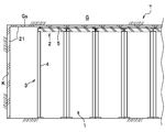
- the tunnel T closes the ground surface Gs exposed by excavating the ground G by a support 1 composed of sprayed concrete 2 or a steel support (panel type support 3). By doing so, it will be stabilized.
- the support work 1 shall include a lock bolt as necessary.
- auxiliary construction methods such as advanced polling, pipe rule construction method, and chemical injection construction may be used together as necessary.
- the ground G is excavated to form an excavation hole (tunnel T) (excavation process).
- the excavation method of the tunnel T is not limited, and may be, for example, blasting type excavation or mechanical excavation.
- the excavation length of the tunnel T for each cycle is determined according to the ground conditions (ground grade, overburden, etc.), but in the present embodiment, it is 1.0 to 1.2 m.
- the support work 1 is formed along the exposed ground surface Gs by excavating the ground G (support step).
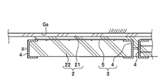
- the support 1 of the present embodiment includes a spray concrete 2 composed of a primary spray concrete 21 and a secondary spray concrete 22, a steel support (support member 4), and a wire mesh 5. It is provided with a panel type support work 3, and the support process includes a primary spraying work, a building-in work, and a secondary spraying work (spraying work).
- the primary spray concrete 21 is sprayed on the ground surface Gs exposed by excavation of the ground G.
- the primary sprayed concrete 21 is sprayed not only on the wall surface (side surface) of the tunnel T but also on the face K.
- the spraying thickness of the primary sprayed concrete 21 may be appropriately determined, but in the present embodiment, it is 5 cm.
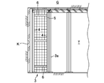
- the panel type support 3 is built along the surface (or the ground surface Gs) of the primary sprayed concrete 21 in the vicinity of the face K. There is a gap between the outer surface of the panel type support 3 (wire mesh 5) and the surface of the primary sprayed concrete 21 that is necessary for adjustment movement during the construction of the panel type support 3 due to extra digging during excavation. (For example, a gap of about 5 cm) is provided.
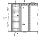
- the panel type support 3 includes a pair of support members 4 and 4 arranged in the front-rear direction, a wire mesh 5 arranged between the support members 4, and a pair of support members. A plurality of connecting steel materials 6 for connecting the members 4 and 4 are provided.
- the length of the panel type support 3 (distance from the end face of the support member 4 on the face K side to the end face of the support member 4 on the wellhead side) is the distance between the steel support members set according to the ground grade (distance between the steel support members 4). In this embodiment, it is 1.0 to 1.2 m).
- the pair of support members 4 and 4 are arranged on the face K side and the wellhead side at intervals in the tunnel axial direction.
- the support member 4 is made of so-called channel steel having a U-shaped cross section formed by a pair of flanges 4a and 4a and a web 4b connecting the pair of flanges 4a and 4a.
- the cross-sectional dimensions of the support member 4 are 1/2 or more of the cross-sectional area of the steel support set by the support pattern according to the ground grade and 1/2 or more of the cross-sectional coefficient of the steel support. The size shall be such that the dimensions having the moment of inertia of area can be secured.
- the support member 4 when the steel support work of the support pattern according to the ground grade is H-125 ⁇ 125 ⁇ 6.5 ⁇ 9 (cross-sectional area: 30.0 cm 2 , section coefficient: 134 cm 3 ), the support member 4 [-125 ⁇ 65 ⁇ 6 ⁇ 8 (cross-sectional area: 17.1 cm 2 , section coefficient: 67.8 cm 3 ) may be used.
- the support member 4 is bent into a shape corresponding to the cross-sectional shape of the tunnel T, and has a front view arc shape.
- the pair of support members 4, 4 are provided so that the tips of the flanges 4a face each other (so that the space surrounded by the pair of flanges 4a, 4a and the web 4b is on the inside).
- the wire mesh 5 is provided along the circumferential direction of the support member 4.
- the wire mesh 5 of the present embodiment has a mesh of 15 ⁇ 15 cm, but the dimensions of the wire mesh 5 are not limited.
- the wire mesh 5 is welded to the outer surface of the flange 4a on the ground G side of the support member 4.
- the wire mesh 5 is laid horizontally between the flange 4a of one support member 4 and the flange 4a of the other support member 4. Since the wire mesh 5 is welded to the front and rear support members 4 and 4, safety is ensured even in the unlikely event of skin loss.
- the connecting steel material 6 is interposed between the support members 4 arranged in the front-rear direction.
- the material constituting the connecting steel material 6 is not limited, and for example, steel materials such as H-shaped steel, channel steel, and L-shaped steel, steel rods, steel pipes, and the like may be used.
- One end of the tether steel 6 is welded to the web 4b of one support member 4, and the other end is welded to the web 4b of the other support member 4.
- the method of fixing the connecting steel material 6 and the support member 4 is not limited, and for example, bolts may be joined.
- the fixing location of the connecting steel material 6 to the support member 4 is not limited, and for example, it may be welded to the inner flange 4a.
- a plurality of connecting steel materials 6, 6, ... Are arranged at intervals along the tunnel wall surface.
- the number of connecting steel materials 6, the arrangement pitch, and the like are not limited, and may be appropriately determined.
- a new panel type support 3 is built on the face K side of the existing panel type support 3a.
- the web 4b of the support member 4 on the wellhead side of the newly installed panel type support 3 is overlapped with the web 4b of the support member 4 on the face K side of the existing panel type support 3a.
- both webs 4b and 4b are connected.
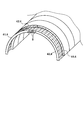
- a pair of left and right panel-type support works 3 and 3 are arranged, and the panel-type support works 3 are combined at the top (upper end) to form an arch-shaped support structure.
- the support members 4 are connected to each other at the top.
- a connecting plate 7 (see FIG. 6) is used to connect the supporting members 4 to each other.
- the connecting plate 7 straddles the left and right support members 4, 4 and is attached to the webs 4b of both support members 4, 4.
- channel steel having a U-shaped cross section is used for the connecting plate 7.
- the connecting plate 7 has a cross-sectional dimension smaller than the cross-sectional dimension of the support member 4, and can be inserted into the space surrounded by the flanges 4a, 4a and the web 4b.
- the connecting plate 7 is attached to the web 4b on the wellhead side of the support member 4 of the existing panel type support 3a and the web 4b on the face K side of the support member 4 of the newly installed panel type support 3, respectively. That is, the top of the support member 4 is sandwiched by the connecting plate 7 from the front and back (face K side and wellhead side) of the support member 4.
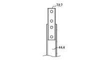
- a plurality of (four in this embodiment) pins 8 are fixed to one connecting plate 7 sandwiching the support member 4, and shown in FIG. 8B to the other connecting plate 7. As described above, through holes are formed at positions corresponding to the plurality of pins 8. Then, the support members 4 are connected to each other by inserting the pins 8 into the connecting plates 7 and 7 that sandwich the support members 4.
- first panel type supporter 31 has a support member 4 on the face K side (hereinafter, "all wings").
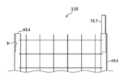
- all wings As shown in FIGS. 6A and 6B, a first connecting plate 71 is fixed to the upper end of the side support member 41).
- the first connecting plate 71 of the present embodiment has a length of 400 mm, and is fixed to the first wing side support member 41 in a state where 200 mm projects from the end of the first wing side support member 41. Has been done.
- the first connecting plate 71 is made of channel steel, and four pins 8, 8, ...
- the method of fixing the first connecting plate 71 to the support member 41 on the wing side is not limited, but in the present embodiment, the first connecting plate 71 is mainly welded to the flanges 4a and 4a. Further, the number of pins 8 fixed to the first connecting plate 71 and the arrangement pitch of the pins 8 are not limited. Further, the materials constituting the first connecting plate 71 and the dimensions of the first connecting plate 71 are not limited. Two through holes are formed at the upper end of the first wing side support member 41 corresponding to the position of the pin 8. The first connecting plate 81 is fixed to the first wing side support member 41 in a state where two pins 8 are passed through the through holes of the first wing side support member 41. The shape of the through hole is such that the pin 8 can be inserted and locked, and in the present embodiment, the inner diameter is about 1 mm larger than the diameter of the pin 8.
- a transmission plate 9 is fixed to the upper end of the wellhead side support member 4 of the first panel type support work 31 (hereinafter, “first wellhead side support member 42”.
- the transmission plate 9 has a width of about 100 mm and a length. It is made of a steel plate of about 200 mm and is welded to each of the flanges 4a and 4a in a space surrounded by the flanges 4a and 4a and the web 4b while being attached to the surface of the web 4b.
- the upper end of the member 42 and the transmission plate 9 are formed with two through holes through which the pin 8 can be inserted.
- a transmission plate 9 is fixed to the upper end of the face side support member 43 ”.
- the transmission plate 9 is made of a steel plate having a width of about 100 mm and a length of about 200 mm, and is attached to each of the flanges 4a and 4a in a space surrounded by the flanges 4a and 4a and the web 4b while being attached to the surface of the web 4b. It is welded.
- the upper end of the second face-side support member 43 and the transmission plate 9 are formed with two through holes through which the pin 8 can be inserted.
- the second connecting plate 72 is fixed to the upper end of the support member 4 on the wellhead side of the second panel type support 32 (hereinafter referred to as "second wellhead side support member 44").
- the second connecting plate 72 has a length of 400 mm, of which 200 mm is overhanging from the end of the second wellhead side support member 44, and the remaining 200 mm is the second wellhead side support member. It is fixed at 44.
- the method of fixing the second connecting plate 72 to the second wellhead side support member 44 is not limited, but in the present embodiment, the second connecting plate 72 is mainly welded to the flanges 4a and 4a.
- the second connecting plate 72 is formed with four through holes for inserting the pin 8. The through hole is formed at a position corresponding to the pin 8 of the first connecting plate 71.
- the first panel type support 31 is arranged on the face K side of the existing panel type support 3a.
- the first panel type support 31 is once arranged with a gap on the face K side of the existing panel type support 3a, and then pulled back to the wellhead side so as to come into contact with the face K side surface of the existing panel type support 3a. ..
- a pin 8 arranged at the top of the support member 4 of the existing panel type support 3a was formed on the first wellhead side support member 42 of the first panel type support 31. It penetrates through the through hole and the through hole formed in the transmission plate 9.
- the panel-type support 3 is held at a predetermined position by arranging and fine-tuning it while being gripped by an erector of a heavy machine or the like.
- the second panel type support 32 is arranged on the face K side of the existing panel type support 1a.
- the second panel type support 32 is once placed with a gap on the face K side of the existing panel type support 3a, and then pulled back to the wellhead side to hit the surface of the existing panel type support 3a on the face K side. Get in touch.
- the pin 8 of the first connecting plate 71 fixed to the top of the first wing side support member 41 is inserted into the through hole formed in the top of the second face side support member 43 and the through hole of the transmission plate 9. Penetrate.
- the pin 8 arranged at the top of the existing panel type support 3a is passed through the through hole formed in the second wellhead side support member 44 and the through hole formed in the second connecting plate 72.
- the support members 4 and 4 of the newly installed left and right panel type support works 3 and 3 and the support members 4 and 4 of the left and right existing panel type support works 3a and 3a are connected.
- the support members 4 and 4 are connected by being sandwiched by the connecting plates 7 and 7 from the front and back in a state of being stacked in an H shape.
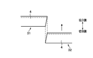
- the tip surface of the support member 4 of the first panel type support 31 (the end surface on the top end side of the tunnel T) approaches the second panel type support 32 side toward the wellhead side. As described above, it is inclined with respect to the tunnel axial direction (moving direction of the second panel type support 32). On the other hand, the tip surface of the support member 4 of the second panel type support 32 is inclined so as to approach the first panel type support 31 side toward the face K side. By doing so, the end faces of the support members 4 are metal-touched to form a support pressure joint so that the axial force can be transmitted.
- the leg portion of the support member 4 of the second panel type support 32 is pushed out (pushed out) to the side (ground G side).
- the second panel type support 32 is designed so that the position when the legs of the support member 4 are pushed out sideways is aligned with the support member 4 of the existing panel type support 3a.
- the support member 4 is extruded so as to apply a bending force of about 10% (about 150 kN / cm) of the yield bending strength of the steel support work.
- a shearing force acts on the pin 8 and the through hole (through hole formed in the connecting plate 7, the web 4b, etc.), and the pin 8 is hard to come out from the through hole due to the frictional force. Therefore, the bondability between the support members 4 is improved.
- a pin is separately arranged on the leg of the support member 4 of the existing panel type support 3a, and a hole is made in advance in the leg of the second panel type support 32. You should plug it into.
- the force for pushing the legs of the support member 4 laterally is not limited. Further, the legs of the support member 4 do not necessarily have to be pushed out to the side.
- the surface of the primary sprayed concrete 21 will be covered with the wire mesh 5.
- the support members 4 adjacent to each other in the front-rear direction or the support members 4 adjacent to each other in the cross-sectional direction may be bolted together.
- the secondary spray concrete 22 is sprayed toward the side surface of the tunnel T (secondary spray work).
- the secondary sprayed concrete 22 is sprayed between the legs of the support work and between the support members 4 arranged in the front and rear (see FIG. 2), and in the present embodiment, the inner air side surface of the support member 4 is exposed. Spraying is performed to a thickness (for example, 10 cm to 25 cm).
- the thickness of the secondary sprayed concrete 22 is not limited, and for example, the flange 2a on the inner air side of the support member 4 may be exposed, or the thickness at which the support member 4 is embedded. There may be.
- the wire mesh 5 is fixed in advance to the support member 4 constituting the steel support, so that the steel support is installed and the wire mesh is installed. Installation with 5 can be performed at the same time. Therefore, it is possible to omit the work of installing the wire mesh 5 in the vicinity of the face K after installing the steel support, and it is possible to improve workability and safety.
- the support members 4 arranged in the front-rear direction are fixed at predetermined intervals, the labor required for positioning the steel support work can be omitted or reduced. Since the support members 4 are firmly connected to each other via the connecting steel material 6, when assembling the panel type support member 3, the support member 4 on the face K side (or the support member 4 on the wellhead side) is gripped by a heavy machine. Can be moved.
- the support member 4 secures the necessary cross-sectional dimensions by combining with the support member 4 of the existing panel type support 3a, it is possible to secure the proof stress as the support structure of the tunnel T.
- the connection between the support members 4 is excellent in workability because it is completed only by passing the pin 8 fixed to one connection plate 7 through the through hole of the support member 4 and inserting it into the other connection plate 7. ..
- the force is transmitted via the connecting plate 7, so that the ability as an arch-shaped support structure can be fully exhibited. That is, stress is transmitted between the first wing side support member 41 and the second wellhead side support member 44 with the connecting plate 7 integrally fixed. That is, the stress acting on the flange 4a of the support member 4 (the first wing side support member 41 or the second wellhead side support member 44) is transmitted to the web 4b and the connecting plate 7 welded to the flange 4a.
- the transmission plate 9 is welded to the flange 4a, the support member 4 (the first wellhead side support member 42 or the second face side support member 42) The stress acting on the flange 4a of 43) is transmitted to the web 4b and the transmission plate 9, and is transmitted to the connecting plate 7 via the pin 8.
- the support members 4 adjacent to each other on the left and right are connected by shear joining between the through holes of the support members 4 and a plurality of (4 in this embodiment) pins 8.
- the bending stress acting on the upper end of the arch (the joint between the support members 4) is transmitted by the plurality of pins 8, and the couple of the shearing forces of the plurality of pins 8 secures the required bending strength.
- ⁇ Second embodiment> a case where tunnel construction is performed by NATM will be described as in the first embodiment.
- the tunnel T closes the ground surface Gs exposed by excavating the ground G by a support 1 composed of sprayed concrete 2 or a steel support (panel type support 3). By doing so, it will be stabilized.
- the support work 1 is formed along the exposed ground surface Gs by excavating the ground G each time the tunnel T is excavated for a predetermined extension (1.0 to 1.2 m in this embodiment).
- the support 1 of the present embodiment includes a spray concrete 2 composed of a primary spray concrete 21 and a secondary spray concrete 22, a steel support (support member 4), a wire mesh 5, and a joint. It is equipped with a panel type support 3 made of steel material 6.
- the primary sprayed concrete 21 is sprayed onto the ground surface Gs exposed by excavation of the ground G.
- the primary sprayed concrete 21 is sprayed not only on the wall surface (side surface) of the tunnel T but also on the face K.
- the spraying thickness of the primary sprayed concrete 21 may be appropriately determined, but in the present embodiment, it is 5 cm.
- the panel type support 3 is built along the surface (or ground surface Gs) of the primary spray concrete 21 in the vicinity of the face K.
- the panel type support 3 includes a pair of support members 4 and 4 arranged in the front-rear direction, a wire mesh 5 arranged between the support members 4, and a pair of support members.
- a plurality of connecting steel materials 6 for connecting the members 4 and 4 are provided.
- the length of the panel type support 3 (distance from the end face of the support member 4 on the face K side to the end face of the support member 4 on the wellhead side) is the distance between the steel support members set according to the ground grade (distance between the steel support members 4). In this embodiment, it is 0.96 to 1.16 m).
- the wire mesh 5 may be installed as needed, and may be omitted depending on the ground grade and the like.
- the pair of support members 4 and 4 are arranged on the face K side and the wellhead side at intervals in the tunnel axial direction.
- the support member 4 is made of so-called channel steel having a U-shaped cross section formed by a pair of flanges 4a and 4a and a web 4b connecting the pair of flanges 4a and 4a.
- the cross-sectional dimensions of the support member 4 are 1/2 or more of the cross-sectional area of the steel support set by the support pattern according to the ground grade and 1/2 or more of the cross-sectional coefficient of the steel support. The size shall be such that the dimensions having the moment of inertia of area can be secured. As shown in FIG.
- the support member 4 is bent into a shape corresponding to the cross-sectional shape of the tunnel T, and has a front view arc shape. As shown in FIG. 20A, the pair of support members 4 and 4 are arranged so that the tips of the flanges 4a face each other (the space surrounded by the pair of flanges 4a and 4a and the web 4b is on the inside). ) It is provided.
- a plurality of stud members 45 are erected (protruded) on the outer surface of the web 4b of the support member 4 (the surface opposite to the other support member 4).
- the head of the stud material 45 of the present embodiment has an enlarged diameter.
- the stud material 45 functions as a ruler for securing a gap of a predetermined size (about 40 mm in this embodiment) between the existing panel type support 3 and the existing panel type support 3 when the panel type support 3 is installed. , Functions as a fixing member to ensure integrity with sprayed concrete.
- the support member 4 provided on the face K side is provided with a receiving metal fitting 46 protruding toward the face K side.
- the receiving metal fitting 46 engages with the support member 4 on the wellhead side of another panel type support 3 provided on the face K side. By doing so, the adjacent support members 4 are connected to each other via the receiving metal fitting 46.
- the receiving metal fitting 46 of the present embodiment includes a main body plate 46a welded to the support member 4 and a protrusion 46b formed at the tip of the main body plate 46a. The protrusion 46b prevents the support member 4 from slipping out and falling when the support member 4 of another panel type support 3 is placed on the receiving metal fitting 46.
- the protrusion 46b is formed at a position where a distance larger than the length obtained by adding the length of the stud member 45 to the width of the flange 4a of the support member 4 is secured from the end surface of the support member 4.
- the protrusion 46b of the present embodiment is formed by fixing another member to the main body plate 46a, but the protrusion 46b may be formed by bending the end portion of the plate material constituting the main body plate 46a.
- the first bottom plate 47a is fixed to the lower end (leg portion) of the support member 4 provided on the face K side.
- the first bottom plate 47a has an outer shape larger than the outer shape of the support member 4 so as to project toward the face K side of the web 4b of the support member 4, and a guide pin 47c is erected on the protruding portion.
- a second bottom plate 47b is fixed to the lower end of the support member 4 on the wellhead side.
- the second bottom plate 47b is formed with a through hole 47d that is inserted into a space surrounded by the flanges 4a and 4a of the support member 4 and the web 4b.
- the guide pin 47c can be inserted through the through hole 47d.
- FIG. 21E when the panel type support 3 is installed, the guide pin 47c of the existing panel type support 3 is inserted into the through hole 47d.
- the wire mesh 5 is provided along the circumferential direction of the support member 4.
- the wire mesh 5 is welded to the outer surface of the flange 4a on the ground G side of the support member 4.
- the wire mesh 5 is laid horizontally between the flange 4a of one support member 4 and the flange 4a of the other support member 4. Since the wire mesh 5 is welded to the front and rear support members 4 and 4, safety is ensured even in the unlikely event of skin loss.
- the connecting steel material 6 is interposed between the support members 4 arranged in the front-rear direction.
- One end of the tether steel 6 is welded to the web 4b of one support member 4, and the other end is welded to the web 4b of the other support member 4.
- a plurality of connecting steel materials 6, 6, ... Are arranged at intervals along the tunnel wall surface.
- the panel type support 3 of the present embodiment is provided with a handle 61 that can be gripped by an elector.
- the handle 61 is made of a steel material and is laid horizontally on a pair of connecting steel materials 6 and 6 adjacent to each other on the shoulder portion.
- the handle 61 is fixed so as to be orthogonal to the connecting steel material 6 in the center of gravity of the panel type support 3 or in the vicinity of the center of gravity.
- the fixing location and orientation of the handle 61 are not limited, and may be fixed to the support member 4, for example.
- the newly installed panel type support 3 will be built on the face K side of the existing panel type support 3a.
- a pair of left and right panel-type support works 3 and 3 are arranged, and the panel-type support works 3 are combined at the top (upper end) to form an arch-shaped support structure 30.
- the support members 4 are connected to each other at the top.
- a joint plate 48 is provided at the tip (upper end) of the support member 4, and when connecting the pair of support members 4 and 4 arranged on the left and right, the joint plate 48 Connect with each other butted.
- one of the pair of left and right support members 4, 4 is provided with a joiner 73 that penetrates the joint plate 48 and projects toward the other support member 4.
- the joiner 73 is a steel material welded to the support member 4, and has a shape in which the vertical width becomes narrower toward the tip.
- the base end portion of the joiner 73 is welded to the support member 4, and the intermediate portion of the joiner 73 is welded to the joint plate 48.
- a joining pin 74 is provided at the tip of the joiner 73.
- the joining pin 74 is provided so as to protrude from the tip of the joiner 73.
- the joint plate 48 of the other support member 4 of the pair of left and right support members 4 and 4 is formed with an opening through which the joiner 73 is inserted.
- a stiffener 75 to which the joining pin 74 can be engaged is fixed to the other support member 4.
- the stiffener 75 is made of a plate material welded and fixed in a space surrounded by the flanges 4a and 4a of the support member 4 and the web 4b, and an engaging hole 76 into which the joining pin 74 can be engaged is formed. ing.
- the panel type support 3 is carried to the face K with the handle 61 grasped by the clamp of the elector (not shown).
- the panel type support 3 is erected by an elector in front of the face, and the position of the panel type support 3 is adjusted relative to the existing panel type support 3a.
- the support member 4 When connecting the pair of left and right support members 4 and 4, the support member 4 is connected by lifting the upper end of the support member 4 with the bottom plate 47 (first bottom plate 47a, second bottom plate 47b) of the support member 4 as a fulcrum. A gap is provided between the joint plates 48 (see FIG. 22B). Next, the upper ends of the left and right support members 4 and 4 are lowered at the same time so that the joiner 73 penetrates the joint plate 48 of the other support member 4 and the joint pin 74 is inserted into the engagement hole 76 of the stiffener 75 (FIG. FIG. See 22A).
- the guide pin 47c erected on the first bottom plate 47a of the existing panel type support 3a is attached to the newly installed panel type support 3.
- the panel type support 3 is arranged in a state of being inserted into the through hole 47d formed in the second bottom plate 47b. Then, the tip of the stud material 45 fixed to the web 4b of the support member 4 on the wellhead side of the new panel type support 3 is brought into contact with the web 4b of the support member 4 on the face K side of the existing panel type support 3a.
- the stud material 45 of the existing panel type support 3a is brought into contact with the web 4b of the support member 4 of the newly installed panel type support 3, so that a gap is formed between the webs 4b (FIG. FIG. See 20A). Further, the support member 4 on the wellhead side of the newly installed panel type support 3 is locked to the metal fitting 46 of the existing panel type support 3a (see FIG. 20A).
- the secondary spray concrete 22 is sprayed toward the side surface of the tunnel T (see FIG. 16).
- the secondary sprayed concrete 22 is sprayed between the legs of the support member 4 and the support members 4 arranged in the front and rear, and in the present embodiment, the thickness (thickness) at which the inner air side surface of the support member 4 is exposed ( For example, spraying is performed at 10 cm to 25 cm).
- the thickness of the secondary sprayed concrete 22 is not limited, and for example, the flange 2a on the inner air side of the support member 4 may be exposed, or the thickness at which the support member 4 is embedded. There may be.
- the secondary spray concrete 22 is also sprayed between the panel type support 3 and the existing panel type support 3a.
- the stud material 45 provided on the support member 4 is embedded in the sprayed concrete sprayed between the panel type support 3s.
- the support members 4 of the panel type support 3 adjacent to each other are connected to each other via the sprayed concrete. Therefore, the support member 4 of the newly installed panel type support 3 and the support member 4 of the existing panel type support 3a can be combined to secure the cross-sectional dimensions required for the steel support, and the tunnel T support structure 30 can be formed. The required yield strength can be secured.
- the joiner 73 since the support members 4 adjacent to each other on the left and right are joined via the joiner 73 at the top, the axial force direction of the support members 4 is supported by the joint plate 48, and the vertical direction (strong axis) is formed by the joiner 73. Bending force in the side) and horizontal direction (weak axis side) is transmitted. Since the joiner 73 has a tapered shape whose cross-sectional shape decreases toward the tip, it is easy to insert the joiner 73 into the joint plate 48. Further, by inserting the joiner 73 into the opening of the joint plate 48, the joiner 73 guides the joint pin 74 to be inserted into the engagement hole 76, so that the jointer 73 can be easily supported only by operating a heavy machine (erector). Members 4 can be joined to each other. Further, since the joint plate 48 and the stiffener 75 are formed at distant positions, the connection state between the support members 4 via the joiner 73 is stable.
- the present invention has been described above.
- the present invention is not limited to the above-described embodiment, and each of the above-mentioned components can be appropriately modified without departing from the spirit of the present invention.
- the support members 4 arranged in the front-rear direction (new support member 4 and the existing support member 4) are connected to each other, but they are adjacent to each other in the front-rear direction.
- the support members 4 may be connected to each other at a portion other than the top.
- both support members 4 may be fixed by pins 8 in a state where both support members 4 are sandwiched by the connecting plate 7 from the front and back on the legs of the support member 4.
- the support members 4 are connected to each other by using the pins 8 or the joining pins 74, but the support members 4 may be bolted. Further, the left and right support members 4 and 4 are connected to each other by engaging the pin 8 provided in one support member 4 with the engagement hole formed in the joint plate 48 of the other support member 4. May be good. Further, in each of the above-described embodiments, the primary sprayed concrete 21 is sprayed after excavation, but the primary sprayed concrete 21 may be constructed according to the ground conditions. That is, the primary sprayed concrete 21 may be omitted in a relatively stable bedrock section.
- the transmission plate 9 may be arranged as needed. Further, in the first embodiment, the pin 8 fixed to one connecting plate 7 is inserted through the other connecting plate 7, but the pin 8 is fixed (fitted and fastened) to the other connecting plate 7. Alternatively, it may be mechanically fixed, etc.).
- the left and right panel type supports 3 and 3 are combined to form an arch shape, but the shape of the panel type support 3 is not limited, and for example, one panel type.
- the support work 3 may be arch-shaped, or may be formed in an arch shape by combining three or more panel-type support works 3.
- the panel type support work 3 the factory-produced one may be carried into the tunnel mine, or the one manufactured on-site may be used.
- the wire mesh 5 may be installed as needed, and may be omitted, for example, in a section of high-quality ground.
- Supporting work Sprayed concrete 3 Panel type supporting work 30 Supporting structure 4 Supporting member 45 Stud material 46 Receiving metal fittings 47 Bottom plate 47a First bottom plate 47b Second bottom plate 47c Guide pin 47d Through hole 48 Joint plate 5 Wire mesh 6 Connecting steel 61 Handle 7 Connecting plate 73 Joiner 74 Joint pin 75 Stiffener 8 pin 9 Transmission plate T tunnel
Landscapes
- Engineering & Computer Science (AREA)
- Mining & Mineral Resources (AREA)
- Life Sciences & Earth Sciences (AREA)
- General Life Sciences & Earth Sciences (AREA)
- Geochemistry & Mineralogy (AREA)
- Geology (AREA)
- Architecture (AREA)
- Civil Engineering (AREA)
- Structural Engineering (AREA)
- Environmental & Geological Engineering (AREA)
- Lining And Supports For Tunnels (AREA)
Priority Applications (1)
| Application Number | Priority Date | Filing Date | Title |
|---|---|---|---|
| JP2022516936A JP7577264B2 (ja) | 2020-04-20 | 2021-04-06 | パネル式支保工、支保構造およびトンネル施工方法 |
Applications Claiming Priority (2)
| Application Number | Priority Date | Filing Date | Title |
|---|---|---|---|
| JP2020074827 | 2020-04-20 | ||
| JP2020-074827 | 2020-04-20 |
Publications (1)
| Publication Number | Publication Date |
|---|---|
| WO2021215235A1 true WO2021215235A1 (ja) | 2021-10-28 |
Family
ID=78269180
Family Applications (1)
| Application Number | Title | Priority Date | Filing Date |
|---|---|---|---|
| PCT/JP2021/014580 Ceased WO2021215235A1 (ja) | 2020-04-20 | 2021-04-06 | パネル式支保工、支保構造およびトンネル施工方法 |
Country Status (2)
| Country | Link |
|---|---|
| JP (1) | JP7577264B2 (https=) |
| WO (1) | WO2021215235A1 (https=) |
Cited By (1)
| Publication number | Priority date | Publication date | Assignee | Title |
|---|---|---|---|---|
| JP7517973B2 (ja) | 2020-12-07 | 2024-07-17 | 戸田建設株式会社 | 鋼製支保工の連結構造及び鋼製支保工の建込み方法 |
Citations (4)
| Publication number | Priority date | Publication date | Assignee | Title |
|---|---|---|---|---|
| JPS5738900U (https=) * | 1980-08-09 | 1982-03-02 | ||
| JPH11159298A (ja) * | 1997-11-28 | 1999-06-15 | Okumura Corp | 支保方法 |
| JP2003082991A (ja) * | 2001-09-05 | 2003-03-19 | Nippon Steel Corp | 既設トンネル覆工の保護構造 |
| JP2008144505A (ja) * | 2006-12-12 | 2008-06-26 | Jfe Metal Products & Engineering Inc | 合成セグメントの連結構造及びこれを備えた合成セグメント |
-
2021
- 2021-04-06 JP JP2022516936A patent/JP7577264B2/ja active Active
- 2021-04-06 WO PCT/JP2021/014580 patent/WO2021215235A1/ja not_active Ceased
Patent Citations (4)
| Publication number | Priority date | Publication date | Assignee | Title |
|---|---|---|---|---|
| JPS5738900U (https=) * | 1980-08-09 | 1982-03-02 | ||
| JPH11159298A (ja) * | 1997-11-28 | 1999-06-15 | Okumura Corp | 支保方法 |
| JP2003082991A (ja) * | 2001-09-05 | 2003-03-19 | Nippon Steel Corp | 既設トンネル覆工の保護構造 |
| JP2008144505A (ja) * | 2006-12-12 | 2008-06-26 | Jfe Metal Products & Engineering Inc | 合成セグメントの連結構造及びこれを備えた合成セグメント |
Cited By (1)
| Publication number | Priority date | Publication date | Assignee | Title |
|---|---|---|---|---|
| JP7517973B2 (ja) | 2020-12-07 | 2024-07-17 | 戸田建設株式会社 | 鋼製支保工の連結構造及び鋼製支保工の建込み方法 |
Also Published As
| Publication number | Publication date |
|---|---|
| JPWO2021215235A1 (https=) | 2021-10-28 |
| JP7577264B2 (ja) | 2024-11-05 |
Similar Documents
| Publication | Publication Date | Title |
|---|---|---|
| WO2011093533A1 (ja) | 鉄骨連続小梁構造 | |
| WO2017047984A1 (ko) | 길이조정이 가능한 강관 지보재와 이를 충진ㆍ강성이 강화된 cft 강관 지보재에 의해 강지보공의 2원화 설치시스템 및 이를 이용한 강지보공의 2원화 시공방법 및 2원화 설치용 강관 지보재 구조 | |
| JP2018131865A (ja) | トンネル支保工 | |
| WO2021215235A1 (ja) | パネル式支保工、支保構造およびトンネル施工方法 | |
| KR101402267B1 (ko) | 근접병설터널 필라부 보강구조체 및 그 시공방법 | |
| KR101222523B1 (ko) | 파형강판을 이용한 프리캐스트 터널구조물 | |
| JP4566914B2 (ja) | 再接合セグメント及び連結トンネルの構築方法 | |
| KR20140015019A (ko) | 아치형 흙막이 벽체 | |
| JP3641783B2 (ja) | 地滑り抑止鋼管組杭の頭部剛結材 | |
| JP5656065B2 (ja) | 鋼板コンクリート構造の構造部材 | |
| JP2005171488A (ja) | 鋼製壁と鉄筋コンクリート版との結合構造 | |
| JP2002220876A (ja) | 建築鉄骨骨組の柱梁部材および接合構造 | |
| JP6535558B2 (ja) | 腹起し | |
| CN111335924A (zh) | 一种锁脚锚管与钢架之间的连接结构及其安装方法 | |
| JP2002309591A (ja) | 杭頭部と鋼製地中梁の接合構造 | |
| KR20160120160A (ko) | 띠장지지 연결부재가 결합된 기성 말뚝 | |
| JP3826348B2 (ja) | 山留め芯材と地下外壁との合成壁の施工方法 | |
| JP7738217B2 (ja) | 支保工継手構造、支保工連結部材および支保工組立方法 | |
| KR20150105613A (ko) | Phc 파일 길이 조정용 스마트 선단캡 및 이를 이용한 파일길이 조정방법 | |
| JP2015078534A (ja) | 合成セグメントおよび合成セグメントの製造方法 | |
| JP6336773B2 (ja) | 山留めh形鋼杭の接合構造および建込み方法 | |
| KR100662774B1 (ko) | 철골보 접합부 연결 장치 | |
| JP2002088782A (ja) | 建築地下骨組の柱・梁接合構造 | |
| JP2025069107A (ja) | 支保工建込方法、支保工ユニットおよび支保工脚部位置修正装置 | |
| JP7517973B2 (ja) | 鋼製支保工の連結構造及び鋼製支保工の建込み方法 |
Legal Events
| Date | Code | Title | Description |
|---|---|---|---|
| 121 | Ep: the epo has been informed by wipo that ep was designated in this application |
Ref document number: 21793786 Country of ref document: EP Kind code of ref document: A1 |
|
| ENP | Entry into the national phase |
Ref document number: 2022516936 Country of ref document: JP Kind code of ref document: A |
|
| NENP | Non-entry into the national phase |
Ref country code: DE |
|
| 122 | Ep: pct application non-entry in european phase |
Ref document number: 21793786 Country of ref document: EP Kind code of ref document: A1 |