WO2021214939A1 - 空気調和機 - Google Patents
空気調和機 Download PDFInfo
- Publication number
- WO2021214939A1 WO2021214939A1 PCT/JP2020/017483 JP2020017483W WO2021214939A1 WO 2021214939 A1 WO2021214939 A1 WO 2021214939A1 JP 2020017483 W JP2020017483 W JP 2020017483W WO 2021214939 A1 WO2021214939 A1 WO 2021214939A1
- Authority
- WO
- WIPO (PCT)
- Prior art keywords
- bell mouth
- air conditioner
- fan casing
- air
- central axis
- Prior art date
- Legal status (The legal status is an assumption and is not a legal conclusion. Google has not performed a legal analysis and makes no representation as to the accuracy of the status listed.)
- Ceased
Links
Images







Classifications
-
- F—MECHANICAL ENGINEERING; LIGHTING; HEATING; WEAPONS; BLASTING
- F04—POSITIVE - DISPLACEMENT MACHINES FOR LIQUIDS; PUMPS FOR LIQUIDS OR ELASTIC FLUIDS
- F04D—NON-POSITIVE-DISPLACEMENT PUMPS
- F04D29/00—Details, component parts, or accessories
- F04D29/40—Casings; Connections of working fluid
- F04D29/42—Casings; Connections of working fluid for radial or helico-centrifugal pumps
- F04D29/44—Fluid-guiding means, e.g. diffusers
-
- F—MECHANICAL ENGINEERING; LIGHTING; HEATING; WEAPONS; BLASTING
- F24—HEATING; RANGES; VENTILATING
- F24F—AIR-CONDITIONING; AIR-HUMIDIFICATION; VENTILATION; USE OF AIR CURRENTS FOR SCREENING
- F24F1/00—Room units for air-conditioning, e.g. separate or self-contained units or units receiving primary air from a central station
- F24F1/0007—Indoor units, e.g. fan coil units
- F24F1/0018—Indoor units, e.g. fan coil units characterised by fans
- F24F1/0022—Centrifugal or radial fans
Definitions
- the present disclosure relates to an air conditioner having a bell mouth and a fan casing to which the bell mouth can be attached.
- Patent Document 1 discloses an air conditioner having a fan casing having a circular suction port and a bell mouth attached to the fan casing.
- the claws provided on the outer peripheral side of the bell mouth are detachably attached to the notches arranged evenly in a circle along the suction port side of the fan casing.
- the shape of a part of the inflow port on the inner peripheral side of the bell mouth may be deformed to be large.
- the claw provided on the outer peripheral side of the bell mouth is the maximum distance between the center of the bell mouth and the outer circumference of the bell mouth. It is arranged in a circle with respect to the position. Therefore, in the circumferential direction of the inflow port of the bell mouth, there is a place where the distance between the outer peripheral side of the bell mouth and the inner peripheral side of the bell mouth is widened, and it is difficult to miniaturize the bell mouth.
- the present disclosure is to solve the above-mentioned problems, and an object of the present disclosure is to provide an air conditioner capable of suppressing the noise of the bell mouth and reducing the size of the bell mouth.
- the air conditioner of the present disclosure has a suction port and an outlet, and has a fan casing for accommodating a fan that blows air from the suction port toward the outlet, and is attached to the fan casing and is attached to the suction port.
- the bell mouth is provided with an annular bell mouth for guiding the air, and the bell mouth has an expansion in which the inner diameter of the upstream opening through which the air flows is larger than the inner diameter of the downstream opening for guiding the air to the suction port. It has a pipe wall, an outer wall provided on the outer peripheral side of the pipe expansion wall, and a hook provided on the outer wall on the downstream side opening side and detachably attached to the fan casing.
- the peripheral edge of the upstream opening has a minimum portion that minimizes the distance from the central axis of the downstream opening and a maximum portion that maximizes the distance of the downstream opening from the central axis.
- a plurality of the hooks are arranged along a virtual arc line centered on a position separated from the central axis in the direction of the maximum portion when viewed from the upstream opening.
- the distance between the expansion wall and the outer wall is provided. Can suppress the spread of. Therefore, in the present disclosure, it is possible to suppress the noise of the bell mouth and to reduce the size of the bell mouth.
- FIG. 6 is a cross-sectional view taken along the line XX of FIG. It is an enlarged view of the area B of FIG. It is a front view of the conventional bell mouth.
- FIG. 10 is a cross-sectional view taken along the line YY of FIG. It is an enlarged view of the area C of FIG. It is a perspective view which showed the state before attaching the bell mouth which concerns on the air conditioner of embodiment to a fan casing. It is a perspective view which looked at the bell mouth which concerns on the air conditioner of embodiment from the front side. It is a perspective view which looked at the bell mouth which concerns on the air conditioner of embodiment from the back side. It is a perspective view which showed the hook of the region D of FIG. 15 enlarged. It is a perspective view which looked at the fan casing which concerns on the air conditioner of embodiment from the front side.
- FIG. 1 is a perspective view schematically showing an example of the air conditioner 100 of the embodiment.
- a floor-standing indoor unit is illustrated as an example of the air conditioner 100, but the present invention is not limited to this.
- the positional relationship between the constituent members of the air conditioner 100 in the following description for example, the positional relationship such as up / down, left / right, front / back, etc., is, in principle, the position when the air conditioner 100 is installed in a usable state. Make a relationship.
- the dimensional relationship and shape of each component may differ from the actual ones.
- the same members or parts or members or parts having the same functions are designated by the same reference numerals or omitted.
- the air conditioner 100 has a box body 1 having an open front surface, an upper design panel 2 covering the upper part of the opened box body 1, and a lower design panel 3 covering the lower part of the opened box body 1.
- the box body 1, the upper design panel 2, and the lower design panel 3 are formed, for example, by molding a thermoplastic resin with plastic.
- the upper design panel 2 is formed with, for example, a blow-out grill 2a having a plurality of rectangular vent holes.
- the lower design panel 3 is formed with, for example, a suction grill 3a having a plurality of rectangular vent holes.
- the air conditioner 100 exchanges heat inside the air conditioner 100 with the air sucked from the suction grill 3a of the lower design panel 3, and blows it out from the blow grill 2a of the upper design panel 2.
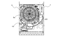
- FIG. 2 is a front view showing a state in which the lower design panel 3 is removed from the air conditioner 100 of FIG.
- FIG. 3 is an enlarged view of the area A of FIG.
- the air conditioner 100 includes a fan guard 5, a bell mouth 10, and a fan casing 20.
- the fan guard 5, the bell mouth 10, and the fan casing 20 are arranged at positions facing the back surface of the lower design panel 3.
- the fan guard 5 is detachably attached to the bell mouth 10.
- the fan guard 5 prevents the fingers of the user of the air conditioner 100 or the maintenance / inspection worker of the air conditioner 100 from being drawn into the bell mouth 10 and the fan casing 20.
- a plurality of arcuate slit holes 5a are concentrically arranged in the fan guard 5 so that the air passing through the suction grill 3a is taken into the bell mouth 10 and the fan guard 5.
- the fan guard 5 may be omitted depending on the application of the air conditioner 100.
- FIG. 4 is an exploded perspective view showing a state in which the bell mouth 10 and the fan casing 20 are removed from the air conditioner 100 of FIG.
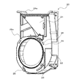
- the fan casing 20 has a housing 22 for accommodating the fan 30 and a duct 24 connected to the housing 22.
- An outlet 24a is formed at the upper end of the duct 24.
- the outlet 24a can be formed in a rectangular shape, for example.
- the housing 22 is formed with a mounting surface 26 for mounting the bell mouth 10.
- a suction port 26a having a circular opening is formed on the mounting surface 26.
- the fan 30 is not limited to, but a centrifugal fan such as a multi-blade sirocco fan or a turbo fan is used.
- the air attracted to the bell mouth 10 is guided from the bell mouth 10 to the suction port 26a by the rotation of the fan 30, and the fan casing 20 is guided through the suction port 26a. It is attracted to the inside of the housing 22. Further, the air attracted to the inside of the housing 22 by the rotation of the fan 30 is blown out from the air outlet 24a formed at the upper end of the duct 24 through the duct 24. Although not shown, the air blown out from the outlet 24a is heat-exchanged by the heat exchanger housed in the box 1. The air heat-exchanged by the heat exchanger is blown out from the blow-out grill 2a of the upper design panel 2.
- FIG. 5 is a front view of the bell mouth 10 according to the air conditioner 100 of the embodiment.
- FIG. 6 is a front view showing a state in which the bell mouth 10 according to the air conditioner 100 of the embodiment is attached to the fan casing 20.
- FIG. 7 is a cross-sectional view taken along the line XX of FIG.
- FIG. 8 is an enlarged view of the area B of FIG.
- FIGS. 9 to 12 The structure of the conventional bell mouth 10X is shown in FIGS. 9 to 12.
- the drawings of the conventional bell mouths 10X of FIGS. 9 to 12 are comparative examples of the drawings of the bell mouths 10 of the present disclosure of FIGS. 5 to 8, respectively.
- FIG. 9 is a front view of the conventional bell mouth 10X.
- FIG. 10 is a front view showing a state in which the conventional bell mouth 10X is attached to the conventional fan casing 20X.
- FIG. 11 is a cross-sectional view taken along the line YY of FIG.
- FIG. 12 is an enlarged view of the region C of FIG.
- a code is displayed only in a portion different from the structure of the present disclosure, and “X” is added to the end of the code of the corresponding structure of the present disclosure. I'm making it.
- the bell mouth 10 of the present disclosure is attached to the fan casing 20 and guides air to the suction port 26a of the fan casing 20.
- the bell mouth 10 is formed, for example, in a ring shape.
- the bell mouth 10 has a tube expansion wall 12 that forms a tapered air passage that guides air to the suction port 26a of the fan casing 20.
- the tube expansion wall 12 has a ring-shaped upstream opening 12a into which air flows in, and a ring-shaped downstream opening 12b that guides air to the suction port 26a of the fan casing 20.
- the pipe expansion wall 12 is formed so that the inner diameter of the upstream opening 12a is larger than the inner diameter of the downstream opening 12b that guides air to the suction port 26a.
- the downstream opening 12b can be formed in a circular shape, for example.
- the downstream opening 12b may have another shape depending on the application or the like, as long as air can be guided to the suction port 26a of the fan casing 20.
- the peripheral edge of the upstream opening 12a has a minimum portion 12a1 which is a point or region of the peripheral edge of the upstream opening 12a where the distance between the central axis O1 and the upstream opening 12a is the minimum distance. ing. Further, the peripheral edge portion of the upstream side opening portion 12a has a maximum portion 12a2 which is a point or region of the peripheral edge portion of the upstream side opening portion 12a where the distance from the central axis O1 is the maximum distance. In FIG.
- the distance between the central axis O1 and the minimum portion 12a1 is indicated by a dotted line arrow as the first distance R1
- the virtual circle IC1 centered on the central axis O1 and having the first distance R1 as the radius is a dotted line. It is indicated by.
- the distance between the central axis O1 and the maximum portion 12a2 is indicated by a solid arrow as the second distance R2.
- the central axis O1 of the downstream opening 12b is a straight line extending in the normal direction from the opening region of the downstream opening 12b.
- the central axis O1 of the downstream opening 12b is a straight line extending in the normal direction in the circular region of the downstream opening 12b and passes through the center of the circle. ..
- the peripheral edge portion of the upstream opening 12a has two curved portions 13 extending between the minimum portion 12a1 and the maximum portion 12a2.
- the curved portion 13 of 2 includes a first curved portion 13a extending clockwise from the minimum portion 12a1 to the maximum portion 12a2, and a second curved portion 13b extending counterclockwise from the minimum portion 12a1 to the maximum portion 12a2.
- the curved portion 13 of 2 is formed in a convex shape when viewed from the central axis O1.
- the curved portion 13 of 2 has at least a part of a region where the distance between the central axis O1 of the downstream opening 12b and the upstream opening 12a changes in the circumferential direction.
- the peripheral edge of the upstream opening 12a is connected to, for example, a semicircular first arc portion having a radius of the first distance R1 and a first arc portion, the first distance R1 having a short radius, and the second distance R2.
- the first arc portion becomes the minimum portion 12a1 of the upstream side opening 12a
- the position of the semimajor axis in the first arc portion becomes the maximum portion 12a2 of the upstream opening 12a.
- the maximum portion 12a2 of the upstream opening 12a is arranged in the direction of the suction grill 3a of the lower design panel 3.
- the noise at the same air volume increases from the maximum portion 12a2 to the minimum portion 12a1. Further, as the air volume passing through the bell mouth 10 increases, the noise increases. Therefore, it is preferable that the maximum portion 12a2 of the upstream opening 12a is arranged in the direction of the suction grill 3a of the lower design panel 3 having a large air volume.
- the extremely small portion 12a1 of the upstream opening 12a is arranged in a direction away from the suction grill 3a of the lower design panel 3 having a large air volume.
- the relative position between the minimum portion 12a1 and the maximum portion 12a2 in the bell mouth 10 is represented by the central angle ⁇ in the clockwise direction between the minimum portion 12a1 and the maximum portion 12a2. If the central angle ⁇ is larger than 90 degrees and smaller than 270 degrees, the extremely small portion 12a1 is arranged in the direction away from the suction grill 3a of the lower design panel 3, so that the generation of noise in the bell mouth 10 can be suppressed.
- the central angle ⁇ is 180 degrees, the minimum portion 12a1 is arranged in the direction farthest from the suction grill 3a of the lower design panel 3, so that the generation of noise in the bell mouth 10 can be further suppressed.
- the direction of the central angle ⁇ is set to the clockwise direction, but the same relationship holds even when the direction of the central angle ⁇ is set to the counterclockwise direction.
- the bell mouth 10 of the present disclosure has an outer wall 14 provided on the outer peripheral side of the tube expansion wall 12.
- the end of the outer wall 14 located on the upstream side opening 12a side of the pipe expansion wall 12 is connected to the peripheral edge portion of the upstream opening 12a.
- the upstream opening 12aX of the tube expansion wall 12X is formed in a circular shape coaxially with the central axis O1X of the downstream opening 12bX.
- the peripheral portion of the upstream opening 12a of the tube expansion wall 12 has a maximum portion 12a2 having a maximum distance from the central axis O1.
- the effect of having the maximum portion 12a2 of the upstream opening 12a of the tube expansion wall 12 is exhibited by the conventional bell mouth in which the upstream opening 12aX of the tube expansion wall 12X is formed in a circular shape. It will be described below in comparison with 10X.
- FIG. 7 shows a cross section of the pipe expansion wall 12 along a cross-sectional line passing through the maximum portion 12a2 of the upstream opening 12a and the central axis O1.
- the length of the cross section of the tube expansion wall 12 at the maximum portion 12a2 of the upstream opening 12a is the length of the cross section of the conventional bell mouth. It is larger than the cross-sectional length of the 10X tube expansion wall 12X. That is, the surface area of the tube expansion wall 12 in the maximum portion 12a2 of the upstream opening 12a is larger than the surface area of the tube expansion wall 12X of the conventional bell mouth 10X.
- the tube expansion wall 12 at the maximum portion 12a2 of the upstream opening 12a suppresses the separation of air attracted to the bell mouth 10 as compared with the tube expansion wall 12X of the conventional bell mouth 10X. Therefore, in the bell mouth 10 of the present disclosure, since the upstream opening 12a of the tube expansion wall 12 has the maximum portion 12a2, the separation of air on the tube expansion wall 12 in the maximum portion 12a2 can be suppressed, and thus the separation of air is performed. Noise can be suppressed.
- FIG. 14 is a perspective view of the bell mouth 10 according to the air conditioner 100 of the embodiment as viewed from the front side.
- FIG. 15 is a perspective view of the bell mouth 10 according to the air conditioner 100 of the embodiment as viewed from the back surface side.
- FIG. 16 is an enlarged perspective view of the hook 16 in the region D of FIG.
- FIG. 17 is a perspective view of the fan casing 20 according to the air conditioner 100 of the embodiment as viewed from the front side.
- FIG. 18 is a perspective view of the fan casing 20 according to the air conditioner 100 of the embodiment as viewed from the back surface side.
- FIG. 14 is a perspective view of the bell mouth 10 according to the air conditioner 100 of the embodiment as viewed from the front side.
- FIG. 15 is a perspective view of the bell mouth 10 according to the air conditioner 100 of the embodiment as viewed from the back surface side.
- FIG. 16 is an enlarged perspective view of the hook 16 in the region D of FIG.
- FIG. 17 is a perspective view of the fan casing
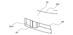
- FIG. 19 is an enlarged perspective view of the mooring hole 28 in the area E of FIG.
- FIG. 20 is a perspective view schematically showing a method of mooring the bell mouth 10 according to the air conditioner 100 of the embodiment to the fan casing 20.
- the direction of rotation when the bell mouth 10 is attached to the fan casing 20 is indicated by an arrow.
- a hook 16 for attaching the bell mouth 10 to the fan casing 20 is provided at the tip of the outer wall 14 located on the downstream side of the bell mouth 10.
- the hook 16 has a claw 16a for mooring the hook 16 to the fan casing 20 and an arm 16b formed as an L-shaped wall.
- the arm 16b has a first arm 16b1 connected to the outer wall 14, and a second arm 16b2 that bends and extends from the tip of the first arm 16b1 and has a claw 16a arranged at the tip.
- the arm 16b has a rib 16b3 that is connected to the first arm 16b1 and the outer wall 14 and reinforces the first arm 16b1.
- the hook 16 is integrally formed with the outer wall 14.
- a window 16c is provided which penetrates the outer wall 14 and is formed so that the claws 16a can be visually recognized.
- a mooring hole 28 is formed on the mounting surface 26 of the fan casing 20 located on the outer peripheral side of the suction port 26a of the fan casing 20.
- the mooring hole 28 is formed as a rectangular or arc-shaped hole.
- the mooring hole 28 is provided with a guide wall 29 having a recess 29a and guiding the claw 16a of the hook 16 to the recess 29a.
- the bell mouth 10 By passing the hook 16 through the mooring hole 28 and mooring it, the bell mouth 10 can be detachably attached to the fan casing 20.
- the hook 16 When attaching the bell mouth 10 to the fan casing 20, the hook 16 is inserted into the mooring hole 28, and the bell mouth 10 is rotated in the direction of the arrow shown in FIG. Let me moor. Further, in order to prevent the bell mouth 10 from being detached from the fan casing 20 by rotating in the direction opposite to the arrow direction shown in FIG. 20, the bell mouth 10 is screwed to the fan casing 20 or the like.
- the number of hooks 16 and mooring holes 28 is not limited, but if at least three are provided, the bell mouth 10 can be stably moored to the fan casing 20.
- FIG. 21 is a front view of the bell mouth 10 according to the air conditioner 100 of the embodiment.
- FIG. 22 is an enlarged view of the region F of FIG. 21.
- the hook 16 and the mooring hole 28 are formed in a virtual arc line IC2 having a center O2 at a position separated from the central axis O1 in the direction of the maximum portion 12a2 of the upstream opening 12a when viewed from the upstream opening 12a. Multiple are arranged along. Further, the hook 16 and the mooring hole 28 are arranged so that the radius R3 of the virtual arc line IC2 is shorter than the second distance R2 between the central axis O1 and the maximum portion 12a2.
- the arrangement positions of the hook 16 and the mooring hole 28 in the long axis direction of the upstream opening 12a can be adjusted so as not to be separated from the upstream opening 12a, so that the miniaturization of the bell mouth 10 is promoted. be able to.
- the hook 16 and the mooring hole 28 are evenly arranged in a circular shape at the position of the second distance R2 about the central axis O1.
- the hook 16 and the mooring hole 28 are arranged at the position of the second distance R2, so that they are arranged at intervals from the position of the minimum portion 12a1. It will be.
- the hook 16 and the mooring hole 28 are arranged along the virtual arc line IC2, they are evenly arranged in an arc shape at a position having a radius R3 shorter than the second distance R2, so that the pipe expansion wall 12 and the outer wall 14 are arranged.
- the content of the present disclosure is not limited to the above-described embodiment, and various modifications can be made without departing from the gist of the present disclosure.
- the configuration of the above-described embodiment can be applied to an air conditioner 100 other than the indoor unit, for example, an outdoor unit and an integrated air conditioner 100.
- the contents of the present disclosure can be applied not only to the air conditioner 100 but also to other refrigeration cycle devices having a bell mouth 10 and a fan casing 20.
Landscapes
- Engineering & Computer Science (AREA)
- Mechanical Engineering (AREA)
- General Engineering & Computer Science (AREA)
- Chemical & Material Sciences (AREA)
- Combustion & Propulsion (AREA)
- Structures Of Non-Positive Displacement Pumps (AREA)
- Air-Conditioning Room Units, And Self-Contained Units In General (AREA)
Priority Applications (3)
| Application Number | Priority Date | Filing Date | Title |
|---|---|---|---|
| CN202080099852.4A CN115398154B (zh) | 2020-04-23 | 2020-04-23 | 空调机 |
| PCT/JP2020/017483 WO2021214939A1 (ja) | 2020-04-23 | 2020-04-23 | 空気調和機 |
| JP2022516577A JP7309053B2 (ja) | 2020-04-23 | 2020-04-23 | 空気調和機 |
Applications Claiming Priority (1)
| Application Number | Priority Date | Filing Date | Title |
|---|---|---|---|
| PCT/JP2020/017483 WO2021214939A1 (ja) | 2020-04-23 | 2020-04-23 | 空気調和機 |
Publications (1)
| Publication Number | Publication Date |
|---|---|
| WO2021214939A1 true WO2021214939A1 (ja) | 2021-10-28 |
Family
ID=78270669
Family Applications (1)
| Application Number | Title | Priority Date | Filing Date |
|---|---|---|---|
| PCT/JP2020/017483 Ceased WO2021214939A1 (ja) | 2020-04-23 | 2020-04-23 | 空気調和機 |
Country Status (3)
| Country | Link |
|---|---|
| JP (1) | JP7309053B2 (https=) |
| CN (1) | CN115398154B (https=) |
| WO (1) | WO2021214939A1 (https=) |
Citations (5)
| Publication number | Priority date | Publication date | Assignee | Title |
|---|---|---|---|---|
| JPS6231225U (https=) * | 1985-08-09 | 1987-02-25 | ||
| JP2002021796A (ja) * | 2000-07-11 | 2002-01-23 | Fuji Industrial Co Ltd | 換気扇 |
| JP2006077585A (ja) * | 2004-09-07 | 2006-03-23 | Mitsubishi Electric Corp | 送風機および空調機 |
| JP2007127089A (ja) * | 2005-11-07 | 2007-05-24 | Daikin Ind Ltd | 遠心送風機及びこれを備えた空気調和装置 |
| JP2011106700A (ja) * | 2009-11-13 | 2011-06-02 | Mitsubishi Heavy Ind Ltd | 空気調和機 |
Family Cites Families (3)
| Publication number | Priority date | Publication date | Assignee | Title |
|---|---|---|---|---|
| CN2455952Y (zh) * | 2000-08-22 | 2001-10-24 | 大金工业株式会社 | 离心风机 |
| US7817421B2 (en) * | 2006-09-13 | 2010-10-19 | Kabushiki Kaisha Yaskawa Denki | Motor controller |
| JP6139954B2 (ja) * | 2013-04-16 | 2017-05-31 | 株式会社デンソー | 流体装置 |
-
2020
- 2020-04-23 CN CN202080099852.4A patent/CN115398154B/zh active Active
- 2020-04-23 JP JP2022516577A patent/JP7309053B2/ja active Active
- 2020-04-23 WO PCT/JP2020/017483 patent/WO2021214939A1/ja not_active Ceased
Patent Citations (5)
| Publication number | Priority date | Publication date | Assignee | Title |
|---|---|---|---|---|
| JPS6231225U (https=) * | 1985-08-09 | 1987-02-25 | ||
| JP2002021796A (ja) * | 2000-07-11 | 2002-01-23 | Fuji Industrial Co Ltd | 換気扇 |
| JP2006077585A (ja) * | 2004-09-07 | 2006-03-23 | Mitsubishi Electric Corp | 送風機および空調機 |
| JP2007127089A (ja) * | 2005-11-07 | 2007-05-24 | Daikin Ind Ltd | 遠心送風機及びこれを備えた空気調和装置 |
| JP2011106700A (ja) * | 2009-11-13 | 2011-06-02 | Mitsubishi Heavy Ind Ltd | 空気調和機 |
Also Published As
| Publication number | Publication date |
|---|---|
| CN115398154B (zh) | 2025-10-28 |
| JP7309053B2 (ja) | 2023-07-14 |
| JPWO2021214939A1 (https=) | 2021-10-28 |
| CN115398154A (zh) | 2022-11-25 |
Similar Documents
| Publication | Publication Date | Title |
|---|---|---|
| US10323650B2 (en) | Centrifugal blower | |
| JP3698150B2 (ja) | 遠心送風機 | |
| JP4380105B2 (ja) | 送風ユニットのファンガード及び空気調和装置 | |
| JP6129431B1 (ja) | 送風機およびこの送風機を搭載した空気調和装置 | |
| JP4690682B2 (ja) | 空調機 | |
| JPWO2001011241A1 (ja) | 送風ユニットのファンガード及び空気調和装置 | |
| WO2007145085A1 (ja) | シャッター機構 | |
| WO2016071948A1 (ja) | プロペラファン、プロペラファン装置および空気調和装置用室外機 | |
| JP6634929B2 (ja) | 遠心送風機 | |
| WO2021214939A1 (ja) | 空気調和機 | |
| JPH0396700A (ja) | 送風装置 | |
| JP6524243B2 (ja) | 空気調和機の室外機 | |
| JP2017125405A (ja) | 遠心送風機 | |
| WO2019215783A1 (ja) | 送風装置及び空気調和装置用室外機 | |
| JP6596951B2 (ja) | 送風装置 | |
| EP3805571A1 (en) | Blower and refrigeration cycle device | |
| JP2016014368A (ja) | 空気調和機 | |
| US10995766B2 (en) | Centrifugal blower | |
| EP3985323A1 (en) | Air conditioner | |
| JP2020020286A (ja) | 空気調和装置 | |
| JP5530879B2 (ja) | 空気調和機の室内機 | |
| JP6654174B2 (ja) | 換気装置 | |
| JP4274229B2 (ja) | 空気調和機 | |
| JP2013204912A (ja) | 室内機 | |
| JP7199390B2 (ja) | 送風装置、熱交換器、換気送風機および空気調和機 |
Legal Events
| Date | Code | Title | Description |
|---|---|---|---|
| 121 | Ep: the epo has been informed by wipo that ep was designated in this application |
Ref document number: 20932193 Country of ref document: EP Kind code of ref document: A1 |
|
| ENP | Entry into the national phase |
Ref document number: 2022516577 Country of ref document: JP Kind code of ref document: A |
|
| NENP | Non-entry into the national phase |
Ref country code: DE |
|
| 122 | Ep: pct application non-entry in european phase |
Ref document number: 20932193 Country of ref document: EP Kind code of ref document: A1 |
|
| WWG | Wipo information: grant in national office |
Ref document number: 202080099852.4 Country of ref document: CN |