WO2021214849A1 - Climatiseur, congélateur et distributeur - Google Patents
Climatiseur, congélateur et distributeur Download PDFInfo
- Publication number
- WO2021214849A1 WO2021214849A1 PCT/JP2020/017126 JP2020017126W WO2021214849A1 WO 2021214849 A1 WO2021214849 A1 WO 2021214849A1 JP 2020017126 W JP2020017126 W JP 2020017126W WO 2021214849 A1 WO2021214849 A1 WO 2021214849A1
- Authority
- WO
- WIPO (PCT)
- Prior art keywords
- pipe
- refrigerant
- distributor
- housing
- opening
- Prior art date
Links
Images


Classifications
-
- F—MECHANICAL ENGINEERING; LIGHTING; HEATING; WEAPONS; BLASTING
- F25—REFRIGERATION OR COOLING; COMBINED HEATING AND REFRIGERATION SYSTEMS; HEAT PUMP SYSTEMS; MANUFACTURE OR STORAGE OF ICE; LIQUEFACTION SOLIDIFICATION OF GASES
- F25B—REFRIGERATION MACHINES, PLANTS OR SYSTEMS; COMBINED HEATING AND REFRIGERATION SYSTEMS; HEAT PUMP SYSTEMS
- F25B41/00—Fluid-circulation arrangements
Definitions
- the present invention relates to an air conditioner, a refrigerator and a distributor.
- radiators for automobiles and air conditioners dedicated to air conditioning parallel flow type heat exchangers are used for the purpose of reducing size, weight, performance, and cost.
- this heat exchanger two header tubes are provided at the openings at both ends of a plurality of flat heat transfer tubes with aluminum fins brazed on the outer surface, and refrigerant is supplied from the inflow side header tube to the outflow side header tube. It is to be fluidized.
- Patent Document 1 discloses a distributor that distributes according to the heat load of the refrigerant circuit downstream of the distributor by providing a plurality of communication pipes having an opening in the gas-liquid mixing portion.
- Patent Document 2 discloses a refrigerant shunt including an inflow pipe, an outflow pipe, and a partition plate arranged at the bottom. In this refrigerant shunt, the distribution accuracy is improved by separating the gas-liquid mixed refrigerant into a liquid refrigerant and a gas refrigerant and then merging them.
- the gas-liquid mixed refrigerant is sucked up from the outflow pipe after separating the gas and liquid, but in order for the outflow pipe to suck up the liquid refrigerant, the liquid refrigerant flowing into the distributor from the inflow port Needs to flow beyond the divider to below the outflow pipe. That is, in a state where a certain amount of liquid refrigerant is not stored in the distributor, the liquid refrigerant cannot exceed the partition plate, and therefore, the liquid refrigerant is distributed to each flow path of the heat exchanger at an appropriate liquid refrigerant flow rate ratio. There is a problem that it is difficult. As described above, in the prior art, there is a problem that the refrigerant may not be distributed at an appropriate liquid refrigerant flow rate ratio.
- the present invention has been made in view of such problems, and an object of the present invention is to distribute a refrigerant at an appropriate liquid refrigerant flow rate ratio.
- the present invention is an air conditioner, comprising a heat exchanger having a plurality of flow paths of the refrigerant and a distributor for distributing the refrigerant to each flow path of the heat exchanger, and the distributor is the distributor. It has an inflow pipe for inflowing refrigerant into the housing of the vessel and a plurality of outflow pipes for flowing out the refrigerant in the housing, and each of the plurality of outflow pipes corresponds to the height of the gas-liquid interface in the housing.
- a first pipe having a first opening in which the ratio of the gas refrigerant and the liquid refrigerant flowing out is changed, a second pipe extending from the inside of the housing to the outside of the housing, the first pipe and the second pipe. It has a connecting part for connecting pipes.
- FIG. 1 Another embodiment of the present invention is a refrigerator, comprising a heat exchanger having a plurality of flow paths of the refrigerant and a distributor for distributing the refrigerant to each flow path of the heat exchanger.
- the distributor has an inflow pipe for flowing the refrigerant into the housing and a plurality of outflow pipes for discharging the refrigerant in the housing, and each of the plurality of outflow pipes has a high gas-liquid interface in the housing.
- a first pipe having a first opening in which the ratio of the gas refrigerant and the liquid refrigerant flowing out correspondingly changes, a second pipe extending from the inside of the housing to the outside of the housing, the first pipe and the above. It has a connecting portion for connecting the second pipe.
- Another embodiment of the present invention is a distributor that distributes the liquid to each flow path of the heat exchanger, and has an inflow pipe that allows the liquid to flow into the housing of the distributor and a plurality of pipes that discharge the liquid from the housing.
- Each of the plurality of outflow pipes has a first opening in which the ratio of the outflow gas refrigerant and the liquid refrigerant changes according to the height of the gas-liquid interface in the housing. It has a pipe, a second pipe extending from the inside of the housing to the outside of the housing, and a connecting portion for connecting the first pipe and the second pipe.
- the refrigerant can be distributed at an appropriate liquid refrigerant flow rate ratio.
- FIG. 5 is a cross-sectional view taken along the line AA of the distributor. It is a perspective view of the connection part and the 1st pipe. It is the figure which looked at the upper surface of the connection part from the top. It is a figure which shows the 1st pipe. It is a figure which shows the opening which concerns on the 2nd modification of 1st Embodiment. It is a figure which shows the opening which concerns on the 2nd modification of 1st Embodiment. It is a figure which shows the connection part which concerns on the 4th modification. It is the schematic sectional drawing of the distributor which concerns on 6th modification.
- FIG. 5 is a cross-sectional view taken along the line BB of the distributor of the second embodiment. It is the schematic sectional drawing of the distributor which concerns on 2nd modification of 2nd Embodiment. It is a figure which shows the side wall of the distributor which concerns on 3rd Embodiment. It is an overall block diagram of the distributor which concerns on 4th Embodiment. It is a perspective view of the connection part and the 1st pipe which concerns on 4th Embodiment. It is a figure which shows the upper surface of the connection part. It is a figure which shows the connection part which concerns on the 3rd modification of 4th Embodiment. It is an overall block diagram of the distributor which concerns on 5th Embodiment. It is an overall block diagram of the air conditioner which concerns on 6th Embodiment. It is an overall block diagram of the refrigerator which concerns on 7th Embodiment.
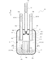
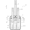
- FIG. 1 is an overall configuration diagram of the distributor 10 according to the first embodiment.
- FIG. 2 is a cross-sectional view taken along the line AA of the distributor 10 shown in FIG.
- the distributor 10 distributes the refrigerant to a plurality of heat transfer tubes of the heat exchanger in the refrigeration cycle.
- the distributor 10 of the present embodiment can supply a refrigerant having an appropriate liquid refrigerant flow ratio to both the parallel flow type heat exchanger and the fin tube type heat exchanger.
- the distributor 10 has a housing 11, one inflow pipe 13, and four outflow pipes 14.
- the housing 161 is a substantially cylindrical housing having the vertical direction H as the longitudinal direction, and has an upper surface 16a, a lower surface 16b, and a side wall 16c.
- the inflow pipe 13 and the outflow pipe 14 are provided along the vertical direction H of the distributor 10. Further, the inflow pipe 13 and the outflow pipe 14 are provided so as to penetrate the upper surface 16a of the housing 11. That is, the upper end 13a of the inflow pipe 13 is located outside the housing 11, and the lower end 13b of the inflow pipe 13 is located inside the housing 11. Similarly, the upper end 14a of the outflow pipe 14 is located outside the housing 11, and the lower end 14b of the outflow pipe 14 is located inside the housing 11.
- the inflow pipe 13 allows the refrigerant to flow into the gas-liquid separation space 12 inside the distributor 10 from the upper surface 16a side (upper portion) of the distributor 10.
- the outflow pipe 14 causes the refrigerant to flow out from the distributor 10 toward the heat exchanger.
- the outflow pipe 14 has a first pipe 211 and a second pipe 22.
- the first pipe 211 is located on the bottom surface 16b side, and the second pipe 22 is connected to the upper part of the first pipe 211 and is provided so as to penetrate the upper surface 16a of the housing 11.
- the first pipe 211 and the second pipe 22 are connected by a connecting portion 181 in the housing 11.
- the connecting portion 181 is arranged below the lower end 13b of the inflow pipe 13. Further, the connecting portion 181 is arranged above the opening 191 of the first pipe 211, that is, downstream of the opening 191 of the first pipe 211 in the outflow pipe 14.
- the plurality of first pipes 211a to 211d are arranged so as to surround the inflow pipe 13.
- the four first pipes 211 are shown as 211a to 212d in order to distinguish them.
- the inflow pipe 13 is arranged at the center position in the lateral direction of the housing 11, and the four first pipes 211a to 211d are arranged on the side wall 16c side of the inflow pipe 13.
- each of the first pipes 211a to 211d is arranged at equal intervals on a predetermined circumference centered on the center position of the housing 11.
- the first pipes 211a to 211d do not necessarily have to be arranged at equal intervals.
- the arrangement of the four second pipes 22 connected to the four first pipes 211a to 211d is the same as the arrangement of the plurality of first pipes 211a to 211d. That is, the second pipe 22 is also arranged at equal intervals on a predetermined circumference on the side wall 16c side of the inflow pipe 13.
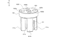
- FIG. 3 is a perspective view of the connection portion 181 and the first pipe 211.
- FIG. 4 is a top view of the upper surface 1811 of the connecting portion 181.
- the connecting portion 181 is a substantially cylindrical component having the vertical direction H as the height direction, and a flat upper surface 1811 extending in the radial direction of the housing 11 is provided on the upper portion.
- the upper surface 1811 is a surface substantially perpendicular to the vertical direction H, that is, substantially parallel to the upper surface 16a and the bottom surface 16b.
- the connecting portion 181 is formed with an opening 1812 penetrating from the upper surface 1811 to the lower surface.
- the four openings 1812 formed in the connecting portion 181 are shown as 1812a, 1812b, 1812c, and 1812d to distinguish them.
- the four openings 1812a to 1812d are arranged at equal intervals on a predetermined circumference on the circular upper surface 1811. That is, the four openings 1812a to 1812d are provided at positions corresponding to the arrangement of the four outflow pipes 14.
- each of the four first pipes 211 (211a to 211d) are connected to the lower side of the connecting portion 181.
- the first pipes 211a to 21d are connected to the connecting portion 181 by brazing or the like so as to be connected to the openings 1812a to 1812d of the connecting portion 181 respectively.
- connection portion 181 shall be made of a metal material. Further, as another example, the connecting portion 181 may be made of a material such as resin. When the material is a resin, it is desirable to use a resin in which the deterioration of the resin by the refrigerant sealed in the refrigeration cycle is within an allowable range.
- connection portion 181 a processing method of the connection portion 181
- a machined structure or a laminated structure (resin molded product) by a 3D printer or the like can be considered.
- variations such as the orientation and shape of the opening can be increased as compared with the method of directly processing the opening on the pipe surface.
- At least one first pipe 211 may be formed integrally with the connection portion 181.
- the first pipe 211 is also made of the same material as the connection portion 18. Then, it is integrally processed and formed.
- the inner diameter of the first pipe 211 is D1
- the inner diameter of the second pipe 22 is D2, which is larger than D1.
- the openings 1812a to 1812d of the connecting portion 181 correspond to this difference in inner diameter, and as shown in FIG. 4, the inner diameter of the connecting portion 181 on the upper surface 1811 side is D2, and the inner diameter on the surface opposite to the upper surface 1811 is D1. It has become. Then, in the openings 1812a to 1812d, the inner diameter is narrowed from D2 to D1 at a predetermined distance from the upper surface 1811 in the vertical direction H. As a result, the connecting portion 181 can connect the first pipe 211 and the second pipe 22 having different inner diameters.
- the second pipe 22 is connected to the openings 1812a to 1812d, and is further connected to the upper surface 16a of the housing 11 by brazing or the like.
- the openings 1812a to 1812d are formed so that the inner diameter thereof is slightly larger than the outer diameter of the second pipe 22. Therefore, in the connection between the second pipe 22 and the openings 1812a to 1812d, a gap is formed between the outer wall of the second pipe 22 and the inner wall of the openings 1812a to 1812d. By forming the gap in this way, even when the first pipe 21 is fixed to the upper surface 16a of the housing 11 in an eccentric state, it absorbs the gap and passes through the opening 1812a. It is possible to connect the first pipe 211 and the second pipe 22.
- FIG. 5 is a diagram showing the first pipe 211.
- Each of the first pipes 211a to 211d is provided with a notch-shaped opening 191 extending upward from the lower end 14b of the outflow pipe 14 (first pipe 211).
- the openings 191 are all provided so as to face the circumferential direction of the distributor 10. In this way, by forming the opening 191 into a shape extending from the lower end 14b, processing can be facilitated.
- the opening 191 is provided so that the center position P in the vertical direction H of the opening 191 is located below the center position Q in the vertical direction of the gas-liquid separation space 12. There is. As a result, it is possible to prevent the opening 191 from reaching the liquid phase in the gas-liquid separation space 12 and sucking up only the gas refrigerant. That is, the liquid refrigerant can be reliably sucked up from the opening 191.
- the central position P of the opening 191 and its longitudinal length are preferably designed according to the height of the gas-liquid interface 17 estimated from the capacity of the refrigeration cycle in which the distributor 10 is used. Specifically, it is preferable to provide the opening 191 at a position and length such that the gas-liquid interface 17 is located between the upper end and the lower end of the opening 191. As a result, the liquid-refrigerant flow rate ratio of the refrigerant flowing out from each outflow pipe 14 can be appropriately maintained. Further, it is assumed that the width of the opening 191 in the lateral direction is half or less of the circumference of the first pipe 211.
- the distributor 10 is installed so that its downward direction corresponds to the direction of gravity. Therefore, the refrigerant flows from the inflow pipe 13 into the housing 11 along the direction of gravity, and flows out from the outflow pipe 14 along the direction opposite to the direction of gravity.
- the gas-liquid mixed refrigerant that has flowed downward from the upper end 13a to the lower end 13b of the inflow pipe 13 and has flowed downward into the gas-liquid separation space 12 comes into contact with the upper surface 1811 of the connecting portion 181. As a result, the direction of the flow of the gas-liquid mixed refrigerant is changed from the downward direction to the side wall 16c side.
- the upper surface 1811 functions as a collision surface on which the gas-liquid mixed refrigerant collides and changes the direction of the flow.
- the gas-liquid mixed refrigerant then flows down along the side wall 16c.
- the flow of the gas-liquid mixed refrigerant is changed from the downward direction to the side wall 16c side, so that gas-liquid separation is promoted.
- the refrigerant falls down along the side wall 16c, it is possible to reduce the disturbance of the gas-liquid interface 17 and the generation of air bubbles. That is, the gas-liquid separation space 12 can be in a state in which the liquid and the gas are well separated.
- the lower region of the opening 191 of the first pipe 211 (outflow pipe 14) is in contact with the liquid at the lower side of the gas-liquid interface 17, and the upper region of the opening 191 is the upper side of the gas-liquid interface 17. Is in contact with gas. Therefore, the liquid refrigerant and the gas refrigerant are sucked up from the outflow pipe 14 at an appropriate liquid refrigerant flow rate ratio. That is, the distributor 10 according to the present embodiment can supply a refrigerant having an appropriate liquid refrigerant flow rate ratio to each flow path of the heat exchanger. Further, the ratio of the area in contact with the gas to the area in contact with the liquid in the opening 191 also changes according to the vertical fluctuation of the gas-liquid interface 17. In other words, the ratio of the gas refrigerant and the liquid refrigerant flowing out from the opening 191 (liquid refrigerant flow ratio) changes according to the height of the gas-liquid interface 17.
- the distributor 10 since the distributor 10 according to the present embodiment separates the gas and liquid, an appropriate liquid-refrigerant flow rate according to the liquid-refrigerant flow rate ratio in the gas-liquid separation space 12 even under medium load conditions and low load conditions.
- the ratio refrigerant can be discharged from the outflow pipe 14 to each flow path of the heat exchanger.
- the liquid refrigerant does not flow into the outflow pipe unless the amount of the liquid refrigerant exceeding the partition plate is accumulated in the distributor.
- the opening 191 is provided in the gas-liquid separation space 12 so that the center position P of the outflow pipe 14 is located below the center position Q of the gas-liquid separation space 12. It is provided below. Therefore, even when the amount of the liquid refrigerant existing in the gas-liquid separation space 12 is small, the outflow pipe 14 can suck up an appropriate amount of the liquid refrigerant.
- the distributor 10 is installed so that the downward direction thereof and the direction of gravity coincide with each other, but in the actual installation state, the downward direction of the distributor 10 and the direction of gravity are slightly different. It shifts. Even when the distributor 10 is tilted in this way, in the distributor 10 of the present embodiment, the plurality of outflow pipes 14 can supply the refrigerant having the same liquid refrigerant flow rate ratio to each flow path of the heat exchanger. ..
- the first pipe 211 and the connecting portion 181 are first connected, and then the second pipe 22 is brazed to the upper surface 16a of the housing 11.
- the first pipe 211 is already connected to the connection portion 181. Therefore, at the time of brazing, it is sufficient to confirm that the connecting portion 181 and the second pipe 22 are joined, and the positions of the gas-liquid interface 17 and the opening 191 can be easily adjusted. That is, the distributor 10 can be assembled more easily than before.
- the number of outflow pipes may be two or more, and is not limited to the embodiment.
- the connection portion 181 described in the first embodiment can be used.
- the outflow pipe 14 is connected only to the two openings 1812a and 1812c of the openings 1812a to 1812d of the connection portion 181.
- a two-branch distributor can be configured.
- the number of branches can be freely changed by using the connecting portion 181 as a common component and adjusting the number of outflow pipes attached to the housing 11.
- the number of outflow pipes may be 6 or 8 or more. In this case, a connecting portion having an opening corresponding to the number of outflow pipes may be used.
- the shape of the opening 191 of the first pipe 211 is not limited to the embodiment.
- the first pipe 212 may be formed with an elongated hole extending in the longitudinal direction of the first pipe 211, that is, in the vertical direction H, as the opening 192.
- the lower end 14b of the outflow pipe 14 may be closed or may be open.
- a plurality of holes 193a to 193g may be formed as the opening 193 in the first pipe 213. Further, it is assumed that the holes 193a to 193g are circular and are provided at equal intervals.
- the center of the opening 193 is an intermediate position (L / 2) of the total length L of the opening 193.
- the positions, sizes, and shapes of the openings 191 of the plurality of outflow pipes 14 may be different from each other. For example, it may be desired to make the liquid-refrigerant flow rate ratio of the refrigerant flowing out to each flow path of the heat exchanger different. In such a case, at least one of the positions and sizes of the plurality of openings 191 may be controlled according to the required liquid-refrigerant flow rate ratio. Further, for example, the opening of one outflow pipe 14 may have an elongated hole shape, while the opening of the other outflow pipe 14 may have a slit shape.
- the shape of the connecting portion 181 is not limited to the embodiment.
- the connecting portion 182 may have a shape having a plurality of piece portions 1821a, 1821b, 1821c, 1821d extending from the center to the respective openings 1822a, 1822b, 1822c, 1822d.
- the refrigerant flowing in from the inflow pipe 13 comes into contact with the connection portion 182, and the direction of the flow is changed from the downward direction to the side wall 16c side.
- the upper surface 1811 of the connecting portion 181 does not have to be a flat surface extending in the lateral direction of the housing 11.
- the upper surface 1811 may be a surface having an upwardly convex gradient.
- the upper surface 1811 may be provided, for example, in a conical shape or a quadrangular shape.
- FIG. 8 is a schematic cross-sectional view of the distributor 10 according to the sixth modification.
- the overhanging portion 60 may be formed on the side wall above the opening 191 in the first pipe 211.
- the overhanging portion 60 projects outward in the radial direction of the first pipe 211.
- the overhanging portion 60 is a plane substantially parallel to the bottom surface 16b.
- the gas-liquid interface 17 changes depending on the operating conditions of the refrigeration cycle, but since the overhanging portion 60 is provided in the vicinity of the gas-liquid interface 17, rippling of the liquid surface is suppressed and the refrigerant flows out from the opening 191. Can be stabilized.
- the relationship between the diameters of the first pipe 211 and the second pipe 22 is not limited to the embodiment. That is, the diameter D1 of the first pipe 211 and the diameter D2 of the second pipe 22 may be equal, and the diameter D1 of the first pipe 211 may be larger than the diameter D2 of the second pipe 22.
- FIG. 9 is a schematic cross-sectional view of the distributor 20 according to the second embodiment.
- FIG. 10 is a cross-sectional view taken along the line BB of the distributor 20 shown in FIG.
- a groove 70 is formed on the bottom surface 16b of the housing 11. As shown in FIG. 10, in the radial direction of the circle of the bottom surface 16b, a recess is formed from the end (outer end 70a) on the side wall 16c side to the inner end (inner end 70b), and an annular groove 70 is provided.
- the groove 70 is an example of a recessed portion.
- the radial width of the groove 70 that is, the distance from the outer end 70a to the inner end 70b is larger than the outer diameter of the first pipe 211.
- the lower ends 14b of the four first pipes 211 are located in the grooves 70.
- the groove 70 and arranging the lower end 14b of the first pipe 211 so as to be located in the groove 70 in this way the positioning of the first pipe 211 is facilitated and the assembleability of the distributor 20 is improved. Can be good.
- the recessed portion as one annular groove 70, processing can be facilitated, and adjustment for locating the first pipe 211 in the recessed portion can be facilitated.
- it is assumed that the lower end 14b of the first pipe 211 is in contact with the bottom surface 70c in the groove 70. However, the lower end 14b may be located in the groove 70 and may not be in contact with the bottom surface 70c.
- a recess is formed in the region of the bottom surface 16b of the housing 11 where the lower end 14b of the outflow pipe 14 is located, and the shape is an annular groove. It is not limited to 70. As another example, four circular recesses may be formed at four locations on the bottom surface 16b where the lower end 14b of the outflow pipe 14 is located.
- FIG. 11 is a schematic cross-sectional view of the distributor 20 according to the second modification.
- the protrusion 80 may be formed in the groove 70.
- the protrusion 80 is arranged at a position where the lower end 14b of the outflow pipe 14 is located.
- at least a part of the protrusion 80 is located inside (inside the pipe) of the first pipe 211, so that the lateral movement of the first pipe 211 is restricted. That is, the installation of the first pipe 211 on the bottom surface 16b of the housing 11 can be stabilized.
- the lower end 14b of the first pipe 211 is open, but as another example, the lower end 14b of the first pipe 211 may be closed.
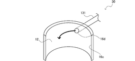
- FIG. 12 is a diagram showing a side wall 16c of the distributor 30 according to the third embodiment.
- the inflow pipe 131 is connected to the opening 16d provided on the upper side of the side wall 16c and communicates with the gas-liquid separation space 12 through the opening 16d.
- the gas-liquid refrigerant flowing in from the opening 16d spirally flows down toward the bottom surface 16b along the side wall 16c. Therefore, the disturbance of the gas-liquid interface 17 due to the inflow of the refrigerant can be reduced, and it is possible to avoid the generation of air bubbles in the liquid phase accumulated under the gas-liquid separation space 12.
- FIG. 13 is an overall configuration diagram of the distributor 40 according to the fourth embodiment.
- FIG. 14 is a perspective view of the connection portion 183 and the first pipe 211 provided in the distributor 40 according to the fourth embodiment.
- FIG. 15 is a top view of the upper surface 1831 of the connecting portion 183.
- an opening 1833 extending in the vertical direction H is provided in the center of the connecting portion 183. It is provided.
- a collision portion 15 is inserted into the opening portion 1833.
- an insertion portion 15a corresponding to the shape of the opening 1833 is provided on the lower side of the collision portion 15, and the upper surface 15b of the collision portion 15 is formed by inserting the insertion portion 15a into the opening 1833. It is arranged on the connection portion 183.
- the upper surface 15b is a surface having an upwardly convex gradient.
- the upper surface 15b is provided, for example, in a conical shape or a quadrangular shape.
- the gas-liquid mixed refrigerant that has flowed downward from the inflow pipe 13 into the gas-liquid separation space 12 comes into contact with the upper surface 15b of the collision portion 15.
- the direction of the flow of the gas-liquid mixed refrigerant is changed from downward to the side wall 16c side, and flows down along the side wall 16c.
- the direction of the flow of the gas-liquid mixed refrigerant is changed from the downward direction to the side wall 16c side, so that the gas-liquid separation is promoted.
- the refrigerant falls down along the side wall 16c, it is possible to reduce the disturbance of the gas-liquid interface 17 and the generation of air bubbles. That is, the gas-liquid separation space 12 can be in a state in which the liquid and the gas are well separated.
- the opening 1833 does not have to penetrate. That is, the connecting portion 183 may have a recessed portion corresponding to the shape of the inserting portion 15a.
- the shape of the upper surface 15b of the collision portion 15 is not limited to the embodiment.
- the upper surface 15b may be a curved surface.
- the upper surface 15b may be a plane substantially parallel to the bottom surface 16b.
- the shape of the connecting portion 183 is not limited to the embodiment.
- the upper surface 1841 of the connecting portion 184 may be formed in a substantially square shape, and four openings 1842a to 1842d may be formed at positions corresponding to each apex of the square.
- a notch portion 1843 extending to the center of the upper surface 1841 may be formed on one side thereof.
- the collision portion 15 may be inserted at the center position of the substantially square of the connection portion 184 in the cutout portion 1843.
- the shape of the connecting portion 183 is not limited to the embodiment, and is not limited to the circle and the square. Further, in the central region of the connecting portion 184, the opening may be formed in a hole shape or a notch shape as long as it penetrates vertically. For example, in the circular connecting portion 183 as described with reference to FIG. 15 in the fourth embodiment, a notch portion extending from the outer circumference to the center may be formed instead of the opening portion 1833.
- FIG. 17 is an overall configuration diagram of the distributor 50 according to the fifth embodiment.
- the connecting portion 183 of the distributor 50 according to the fifth embodiment is the same as the connecting portion 183 according to the fourth embodiment, and has an opening 1833 in the center.
- the inflow pipe 13 is connected so that the refrigerant flows into the housing 11 from the lower part to the upper part of the housing 11.
- the inflow pipe 13 is provided so as to penetrate the bottom surface 16b and the connecting portion 183.
- the lower end 13b of the inflow pipe 13 is located below the housing 11, and the upper end 13a of the inflow pipe 13 is located between the connection portion 183 and the upper surface 16a in the housing 11.
- the gas-liquid mixed refrigerant that has flowed into the gas-liquid separation space 12 from the inflow pipe 13 comes into contact with the upper surface 16a of the housing 11 and the direction of flow is from upward to the side wall 16c side. It is changed and flows down along the side wall 16c. In this way, the direction of the flow is changed from the upward direction to the side wall 16c side, so that gas-liquid separation is promoted. Further, since the refrigerant falls down along the side wall 16c, it is possible to reduce the disturbance of the gas-liquid interface 17 and the generation of air bubbles. That is, the gas-liquid separation space 12 can be in a state in which the liquid and the gas are well separated. Further, the connection unit 183 can be shared with the connection unit 183 of the distributor 40 described in the fourth embodiment.
- FIG. 18 is an overall configuration diagram of the air conditioner 300 according to the sixth embodiment.
- the distributor according to any one of the first to fifth embodiments is applied to the air conditioner 300.
- the air conditioner 300 includes an indoor unit 310 and an outdoor unit 320.
- the indoor unit 310 and the outdoor unit 320 are connected by a liquid pipe 331 and a gas pipe 332 to form a refrigeration cycle.
- the indoor unit 310 includes an indoor heat exchanger 311, an indoor blower 312, and an indoor expansion valve 313.
- An indoor distributor 314 is provided between the indoor expansion valve 313 and the indoor heat exchanger 311.
- the outdoor unit 320 includes an outdoor heat exchanger 321, an outdoor blower 322, a compressor 323, a four-way valve 324, and an outdoor expansion valve 325.
- An outdoor distributor 326 is provided between the outdoor expansion valve 325 and the outdoor heat exchanger 321.
- the indoor distributor 314 and the outdoor distributor 326 are any of the distributors 10, 20, 30, 40, and 50 described in the first to fifth embodiments.
- the refrigerant 341 that has become hot and high pressure in the compressor 323 is guided to the indoor heat exchanger 311 (condenser) in the indoor unit 310 via the four-way valve 324. Then, the high-temperature refrigerant flowing through the indoor heat exchanger 311 dissipates heat to the indoor air supplied from the indoor blower 312, thereby warming the room. At this time, the gas refrigerant that has been deprived of heat gradually liquefies in the indoor heat exchanger 311, and the overcooled liquid refrigerant flows out from the outlet of the indoor heat exchanger 311 via the indoor distributor 314. do.
- the liquid refrigerant flowing out from the indoor unit 310 via the indoor expansion valve 313 becomes a gas-liquid two-phase refrigerant in a low temperature / low pressure state due to the expansion action when passing through the outdoor expansion valve 325.
- the low-temperature / low-pressure gas-liquid two-phase refrigerant is distributed by the outdoor distributor 326 and guided to a plurality of flow paths of the outdoor heat exchanger 321 (evaporator). Then, the low-temperature refrigerant flowing through the outdoor heat exchanger 321 absorbs heat from the outside air supplied from the outdoor blower 322. At the outlet of the outdoor heat exchanger 321 the refrigerant gasifies and returns to the compressor 323.
- the heating operation of the air conditioner 300 is realized by a series of refrigeration cycles in which the refrigerant 341 circulates counterclockwise as described above.
- the four-way valve 324 is switched to form a refrigeration cycle in which the refrigerant 341 circulates clockwise.
- the indoor heat exchanger 311 acts as an evaporator and the outdoor heat exchanger 321 acts as a condenser.
- FIG. 19 is an overall configuration diagram of the refrigerator 400 according to the seventh embodiment.
- the distributor according to any one of the first to fifth embodiments is applied to the refrigerator 400.
- a refrigerating cycle is composed of a compressor 401, a condenser 402, an expansion valve 403, a distributor 404, and an evaporator 405.
- the distributor 404 is any of the distributors 10, 20, 30, 40, and 50 described in the first to fifth embodiments.
- the refrigerant that has become hot and high pressure in the compressor 401 is condensed in the condenser 402 to become a liquid refrigerant.
- the low-temperature low-pressure liquid refrigerant decompressed by the expansion valve 403 is distributed to a plurality of flow paths by the distributor 404 and then supplied to the evaporator 405.
- the evaporator 405 heat is exchanged to become a gas refrigerant and return to the compressor 401.
- the cooler 406 cools the condenser 402 by flowing cooling water through the condenser 402.
Landscapes
- Engineering & Computer Science (AREA)
- Physics & Mathematics (AREA)
- Mechanical Engineering (AREA)
- Thermal Sciences (AREA)
- General Engineering & Computer Science (AREA)
- Heat-Exchange Devices With Radiators And Conduit Assemblies (AREA)
- Details Of Heat-Exchange And Heat-Transfer (AREA)
Abstract
Le problème décrit par la présente invention concerne la distribution d'un réfrigérant à un rapport d'écoulement de réfrigérant liquide approprié. La solution selon l'invention porte sur un échangeur de chaleur présentant une pluralité de trajets d'écoulement pour un réfrigérant et un distributeur qui distribue le réfrigérant aux trajets d'écoulement de l'échangeur de chaleur, le distributeur comprenant un tuyau d'entrée à travers lequel le réfrigérant s'écoule dans un boîtier du distributeur et une pluralité de tuyaux de sortie à travers lesquels le réfrigérant dans le boîtier s'écoule vers l'extérieur ; et chaque tuyau de la pluralité de tuyaux de sortie présente un premier tuyau, qui présente une première ouverture dans laquelle les proportions d'un réfrigérant gazeux et d'un réfrigérant liquide s'écoulant vers l'extérieur changent en fonction de la hauteur d'une interface gaz-liquide dans le boîtier, un deuxième tuyau qui s'étend depuis l'intérieur du boîtier vers l'extérieur du boîtier et une section de raccordement qui raccorde le premier tuyau et le deuxième tuyau.
Priority Applications (3)
| Application Number | Priority Date | Filing Date | Title |
|---|---|---|---|
| PCT/JP2020/017126 WO2021214849A1 (fr) | 2020-04-21 | 2020-04-21 | Climatiseur, congélateur et distributeur |
| JP2020560856A JP6977184B1 (ja) | 2020-04-21 | 2020-04-21 | 空気調和機、冷凍機及び分配器 |
| CN202080003285.8A CN113906262B (zh) | 2020-04-21 | 2020-04-21 | 空调机、冷冻机以及分配器 |
Applications Claiming Priority (1)
| Application Number | Priority Date | Filing Date | Title |
|---|---|---|---|
| PCT/JP2020/017126 WO2021214849A1 (fr) | 2020-04-21 | 2020-04-21 | Climatiseur, congélateur et distributeur |
Publications (1)
| Publication Number | Publication Date |
|---|---|
| WO2021214849A1 true WO2021214849A1 (fr) | 2021-10-28 |
Family
ID=78270384
Family Applications (1)
| Application Number | Title | Priority Date | Filing Date |
|---|---|---|---|
| PCT/JP2020/017126 WO2021214849A1 (fr) | 2020-04-21 | 2020-04-21 | Climatiseur, congélateur et distributeur |
Country Status (3)
| Country | Link |
|---|---|
| JP (1) | JP6977184B1 (fr) |
| CN (1) | CN113906262B (fr) |
| WO (1) | WO2021214849A1 (fr) |
Citations (6)
| Publication number | Priority date | Publication date | Assignee | Title |
|---|---|---|---|---|
| JPH0621745B2 (ja) * | 1988-03-23 | 1994-03-23 | 株式会社東芝 | 気液二相流体分配器 |
| JP2001050613A (ja) * | 1999-08-10 | 2001-02-23 | Daikin Ind Ltd | 冷媒分配器 |
| JP2001091105A (ja) * | 1999-09-22 | 2001-04-06 | Mitsubishi Electric Corp | 冷媒分配器とその製造方法 |
| JP2001304722A (ja) * | 2000-04-26 | 2001-10-31 | Daikin Ind Ltd | 冷媒分流器及びその製造方法 |
| JP2005114214A (ja) * | 2003-10-06 | 2005-04-28 | Sharp Corp | 冷媒分流器 |
| KR20130035817A (ko) * | 2011-09-30 | 2013-04-09 | 주식회사 에이치앤이 | 유체 균일 분배기기 |
Family Cites Families (2)
| Publication number | Priority date | Publication date | Assignee | Title |
|---|---|---|---|---|
| JP2012137223A (ja) * | 2010-12-27 | 2012-07-19 | Hitachi Appliances Inc | 熱交換器の分流器並びにその分流器を備えた冷凍サイクル装置及び空気調和機 |
| JP2018162901A (ja) * | 2017-03-24 | 2018-10-18 | 日立ジョンソンコントロールズ空調株式会社 | 熱交換器、および、それを用いた空気調和機 |
-
2020
- 2020-04-21 JP JP2020560856A patent/JP6977184B1/ja active Active
- 2020-04-21 CN CN202080003285.8A patent/CN113906262B/zh active Active
- 2020-04-21 WO PCT/JP2020/017126 patent/WO2021214849A1/fr active Application Filing
Patent Citations (6)
| Publication number | Priority date | Publication date | Assignee | Title |
|---|---|---|---|---|
| JPH0621745B2 (ja) * | 1988-03-23 | 1994-03-23 | 株式会社東芝 | 気液二相流体分配器 |
| JP2001050613A (ja) * | 1999-08-10 | 2001-02-23 | Daikin Ind Ltd | 冷媒分配器 |
| JP2001091105A (ja) * | 1999-09-22 | 2001-04-06 | Mitsubishi Electric Corp | 冷媒分配器とその製造方法 |
| JP2001304722A (ja) * | 2000-04-26 | 2001-10-31 | Daikin Ind Ltd | 冷媒分流器及びその製造方法 |
| JP2005114214A (ja) * | 2003-10-06 | 2005-04-28 | Sharp Corp | 冷媒分流器 |
| KR20130035817A (ko) * | 2011-09-30 | 2013-04-09 | 주식회사 에이치앤이 | 유체 균일 분배기기 |
Also Published As
| Publication number | Publication date |
|---|---|
| CN113906262B (zh) | 2023-08-29 |
| CN113906262A (zh) | 2022-01-07 |
| JP6977184B1 (ja) | 2021-12-08 |
| JPWO2021214849A1 (fr) | 2021-10-28 |
Similar Documents
| Publication | Publication Date | Title |
|---|---|---|
| JP6202451B2 (ja) | 熱交換器及び空気調和機 | |
| JP4887213B2 (ja) | 冷媒分配器及び空気調和機 | |
| US20080105420A1 (en) | Parallel Flow Heat Exchanger With Crimped Channel Entrance | |
| JP4358981B2 (ja) | 空調用凝縮器 | |
| US11022372B2 (en) | Air conditioner | |
| EP2869000B1 (fr) | Cycle de réfrigération d'un réfrigérateur | |
| WO2018173356A1 (fr) | Échangeur de chaleur et climatiseur faisant appel audit échangeur | |
| US10041710B2 (en) | Heat exchanger and air conditioner | |
| WO2018116929A1 (fr) | Échangeur de chaleur et climatiseur | |
| JPH109713A (ja) | 冷媒凝縮装置、および冷媒凝縮器 | |
| WO2006053311A2 (fr) | Evaporateur a flux paralleles dote de collecteurs façonnes | |
| JP2021017991A (ja) | 熱交換器、空気調和装置、室内機および室外機 | |
| JP5975971B2 (ja) | 熱交換器及び冷凍サイクル装置 | |
| WO2022264348A1 (fr) | Échangeur de chaleur et dispositif à cycle de réfrigération | |
| JP6169199B2 (ja) | 熱交換器及び冷凍サイクル装置 | |
| JP2001174103A (ja) | 冷媒凝縮器 | |
| WO2021214849A1 (fr) | Climatiseur, congélateur et distributeur | |
| JP2020112274A (ja) | 熱交換器 | |
| EP3715760B1 (fr) | Dérivation d'échangeur de chaleur | |
| US11493277B2 (en) | Microchannel heat exchanger | |
| JP6766980B1 (ja) | 熱交換器及び熱交換器を搭載した空気調和装置 | |
| JP2020115070A (ja) | 熱交換器 | |
| WO2020178930A1 (fr) | Appareil de climatisation, machine frigorifique et distributeur | |
| EP3715761B1 (fr) | Dérivation d'échangeur de chaleur | |
| EP4163572A1 (fr) | Distributeur de fluide frigorigène, échangeur de chaleur, et dispositif de climatisation |
Legal Events
| Date | Code | Title | Description |
|---|---|---|---|
| ENP | Entry into the national phase |
Ref document number: 2020560856 Country of ref document: JP Kind code of ref document: A |
|
| 121 | Ep: the epo has been informed by wipo that ep was designated in this application |
Ref document number: 20932041 Country of ref document: EP Kind code of ref document: A1 |
|
| NENP | Non-entry into the national phase |
Ref country code: DE |
|
| 122 | Ep: pct application non-entry in european phase |
Ref document number: 20932041 Country of ref document: EP Kind code of ref document: A1 |