WO2021214849A1 - Air conditioner, freezer, and distributor - Google Patents
Air conditioner, freezer, and distributor Download PDFInfo
- Publication number
- WO2021214849A1 WO2021214849A1 PCT/JP2020/017126 JP2020017126W WO2021214849A1 WO 2021214849 A1 WO2021214849 A1 WO 2021214849A1 JP 2020017126 W JP2020017126 W JP 2020017126W WO 2021214849 A1 WO2021214849 A1 WO 2021214849A1
- Authority
- WO
- WIPO (PCT)
- Prior art keywords
- pipe
- refrigerant
- distributor
- housing
- opening
- Prior art date
Links
Images


Classifications
-
- F—MECHANICAL ENGINEERING; LIGHTING; HEATING; WEAPONS; BLASTING
- F25—REFRIGERATION OR COOLING; COMBINED HEATING AND REFRIGERATION SYSTEMS; HEAT PUMP SYSTEMS; MANUFACTURE OR STORAGE OF ICE; LIQUEFACTION SOLIDIFICATION OF GASES
- F25B—REFRIGERATION MACHINES, PLANTS OR SYSTEMS; COMBINED HEATING AND REFRIGERATION SYSTEMS; HEAT PUMP SYSTEMS
- F25B41/00—Fluid-circulation arrangements
Definitions
- the present invention relates to an air conditioner, a refrigerator and a distributor.
- radiators for automobiles and air conditioners dedicated to air conditioning parallel flow type heat exchangers are used for the purpose of reducing size, weight, performance, and cost.
- this heat exchanger two header tubes are provided at the openings at both ends of a plurality of flat heat transfer tubes with aluminum fins brazed on the outer surface, and refrigerant is supplied from the inflow side header tube to the outflow side header tube. It is to be fluidized.
- Patent Document 1 discloses a distributor that distributes according to the heat load of the refrigerant circuit downstream of the distributor by providing a plurality of communication pipes having an opening in the gas-liquid mixing portion.
- Patent Document 2 discloses a refrigerant shunt including an inflow pipe, an outflow pipe, and a partition plate arranged at the bottom. In this refrigerant shunt, the distribution accuracy is improved by separating the gas-liquid mixed refrigerant into a liquid refrigerant and a gas refrigerant and then merging them.
- the gas-liquid mixed refrigerant is sucked up from the outflow pipe after separating the gas and liquid, but in order for the outflow pipe to suck up the liquid refrigerant, the liquid refrigerant flowing into the distributor from the inflow port Needs to flow beyond the divider to below the outflow pipe. That is, in a state where a certain amount of liquid refrigerant is not stored in the distributor, the liquid refrigerant cannot exceed the partition plate, and therefore, the liquid refrigerant is distributed to each flow path of the heat exchanger at an appropriate liquid refrigerant flow rate ratio. There is a problem that it is difficult. As described above, in the prior art, there is a problem that the refrigerant may not be distributed at an appropriate liquid refrigerant flow rate ratio.
- the present invention has been made in view of such problems, and an object of the present invention is to distribute a refrigerant at an appropriate liquid refrigerant flow rate ratio.
- the present invention is an air conditioner, comprising a heat exchanger having a plurality of flow paths of the refrigerant and a distributor for distributing the refrigerant to each flow path of the heat exchanger, and the distributor is the distributor. It has an inflow pipe for inflowing refrigerant into the housing of the vessel and a plurality of outflow pipes for flowing out the refrigerant in the housing, and each of the plurality of outflow pipes corresponds to the height of the gas-liquid interface in the housing.
- a first pipe having a first opening in which the ratio of the gas refrigerant and the liquid refrigerant flowing out is changed, a second pipe extending from the inside of the housing to the outside of the housing, the first pipe and the second pipe. It has a connecting part for connecting pipes.
- FIG. 1 Another embodiment of the present invention is a refrigerator, comprising a heat exchanger having a plurality of flow paths of the refrigerant and a distributor for distributing the refrigerant to each flow path of the heat exchanger.
- the distributor has an inflow pipe for flowing the refrigerant into the housing and a plurality of outflow pipes for discharging the refrigerant in the housing, and each of the plurality of outflow pipes has a high gas-liquid interface in the housing.
- a first pipe having a first opening in which the ratio of the gas refrigerant and the liquid refrigerant flowing out correspondingly changes, a second pipe extending from the inside of the housing to the outside of the housing, the first pipe and the above. It has a connecting portion for connecting the second pipe.
- Another embodiment of the present invention is a distributor that distributes the liquid to each flow path of the heat exchanger, and has an inflow pipe that allows the liquid to flow into the housing of the distributor and a plurality of pipes that discharge the liquid from the housing.
- Each of the plurality of outflow pipes has a first opening in which the ratio of the outflow gas refrigerant and the liquid refrigerant changes according to the height of the gas-liquid interface in the housing. It has a pipe, a second pipe extending from the inside of the housing to the outside of the housing, and a connecting portion for connecting the first pipe and the second pipe.
- the refrigerant can be distributed at an appropriate liquid refrigerant flow rate ratio.
- FIG. 5 is a cross-sectional view taken along the line AA of the distributor. It is a perspective view of the connection part and the 1st pipe. It is the figure which looked at the upper surface of the connection part from the top. It is a figure which shows the 1st pipe. It is a figure which shows the opening which concerns on the 2nd modification of 1st Embodiment. It is a figure which shows the opening which concerns on the 2nd modification of 1st Embodiment. It is a figure which shows the connection part which concerns on the 4th modification. It is the schematic sectional drawing of the distributor which concerns on 6th modification.
- FIG. 5 is a cross-sectional view taken along the line BB of the distributor of the second embodiment. It is the schematic sectional drawing of the distributor which concerns on 2nd modification of 2nd Embodiment. It is a figure which shows the side wall of the distributor which concerns on 3rd Embodiment. It is an overall block diagram of the distributor which concerns on 4th Embodiment. It is a perspective view of the connection part and the 1st pipe which concerns on 4th Embodiment. It is a figure which shows the upper surface of the connection part. It is a figure which shows the connection part which concerns on the 3rd modification of 4th Embodiment. It is an overall block diagram of the distributor which concerns on 5th Embodiment. It is an overall block diagram of the air conditioner which concerns on 6th Embodiment. It is an overall block diagram of the refrigerator which concerns on 7th Embodiment.
- FIG. 1 is an overall configuration diagram of the distributor 10 according to the first embodiment.
- FIG. 2 is a cross-sectional view taken along the line AA of the distributor 10 shown in FIG.
- the distributor 10 distributes the refrigerant to a plurality of heat transfer tubes of the heat exchanger in the refrigeration cycle.
- the distributor 10 of the present embodiment can supply a refrigerant having an appropriate liquid refrigerant flow ratio to both the parallel flow type heat exchanger and the fin tube type heat exchanger.
- the distributor 10 has a housing 11, one inflow pipe 13, and four outflow pipes 14.
- the housing 161 is a substantially cylindrical housing having the vertical direction H as the longitudinal direction, and has an upper surface 16a, a lower surface 16b, and a side wall 16c.
- the inflow pipe 13 and the outflow pipe 14 are provided along the vertical direction H of the distributor 10. Further, the inflow pipe 13 and the outflow pipe 14 are provided so as to penetrate the upper surface 16a of the housing 11. That is, the upper end 13a of the inflow pipe 13 is located outside the housing 11, and the lower end 13b of the inflow pipe 13 is located inside the housing 11. Similarly, the upper end 14a of the outflow pipe 14 is located outside the housing 11, and the lower end 14b of the outflow pipe 14 is located inside the housing 11.
- the inflow pipe 13 allows the refrigerant to flow into the gas-liquid separation space 12 inside the distributor 10 from the upper surface 16a side (upper portion) of the distributor 10.
- the outflow pipe 14 causes the refrigerant to flow out from the distributor 10 toward the heat exchanger.
- the outflow pipe 14 has a first pipe 211 and a second pipe 22.
- the first pipe 211 is located on the bottom surface 16b side, and the second pipe 22 is connected to the upper part of the first pipe 211 and is provided so as to penetrate the upper surface 16a of the housing 11.
- the first pipe 211 and the second pipe 22 are connected by a connecting portion 181 in the housing 11.
- the connecting portion 181 is arranged below the lower end 13b of the inflow pipe 13. Further, the connecting portion 181 is arranged above the opening 191 of the first pipe 211, that is, downstream of the opening 191 of the first pipe 211 in the outflow pipe 14.
- the plurality of first pipes 211a to 211d are arranged so as to surround the inflow pipe 13.
- the four first pipes 211 are shown as 211a to 212d in order to distinguish them.
- the inflow pipe 13 is arranged at the center position in the lateral direction of the housing 11, and the four first pipes 211a to 211d are arranged on the side wall 16c side of the inflow pipe 13.
- each of the first pipes 211a to 211d is arranged at equal intervals on a predetermined circumference centered on the center position of the housing 11.
- the first pipes 211a to 211d do not necessarily have to be arranged at equal intervals.
- the arrangement of the four second pipes 22 connected to the four first pipes 211a to 211d is the same as the arrangement of the plurality of first pipes 211a to 211d. That is, the second pipe 22 is also arranged at equal intervals on a predetermined circumference on the side wall 16c side of the inflow pipe 13.
- FIG. 3 is a perspective view of the connection portion 181 and the first pipe 211.
- FIG. 4 is a top view of the upper surface 1811 of the connecting portion 181.
- the connecting portion 181 is a substantially cylindrical component having the vertical direction H as the height direction, and a flat upper surface 1811 extending in the radial direction of the housing 11 is provided on the upper portion.
- the upper surface 1811 is a surface substantially perpendicular to the vertical direction H, that is, substantially parallel to the upper surface 16a and the bottom surface 16b.
- the connecting portion 181 is formed with an opening 1812 penetrating from the upper surface 1811 to the lower surface.
- the four openings 1812 formed in the connecting portion 181 are shown as 1812a, 1812b, 1812c, and 1812d to distinguish them.
- the four openings 1812a to 1812d are arranged at equal intervals on a predetermined circumference on the circular upper surface 1811. That is, the four openings 1812a to 1812d are provided at positions corresponding to the arrangement of the four outflow pipes 14.
- each of the four first pipes 211 (211a to 211d) are connected to the lower side of the connecting portion 181.
- the first pipes 211a to 21d are connected to the connecting portion 181 by brazing or the like so as to be connected to the openings 1812a to 1812d of the connecting portion 181 respectively.
- connection portion 181 shall be made of a metal material. Further, as another example, the connecting portion 181 may be made of a material such as resin. When the material is a resin, it is desirable to use a resin in which the deterioration of the resin by the refrigerant sealed in the refrigeration cycle is within an allowable range.
- connection portion 181 a processing method of the connection portion 181
- a machined structure or a laminated structure (resin molded product) by a 3D printer or the like can be considered.
- variations such as the orientation and shape of the opening can be increased as compared with the method of directly processing the opening on the pipe surface.
- At least one first pipe 211 may be formed integrally with the connection portion 181.
- the first pipe 211 is also made of the same material as the connection portion 18. Then, it is integrally processed and formed.
- the inner diameter of the first pipe 211 is D1
- the inner diameter of the second pipe 22 is D2, which is larger than D1.
- the openings 1812a to 1812d of the connecting portion 181 correspond to this difference in inner diameter, and as shown in FIG. 4, the inner diameter of the connecting portion 181 on the upper surface 1811 side is D2, and the inner diameter on the surface opposite to the upper surface 1811 is D1. It has become. Then, in the openings 1812a to 1812d, the inner diameter is narrowed from D2 to D1 at a predetermined distance from the upper surface 1811 in the vertical direction H. As a result, the connecting portion 181 can connect the first pipe 211 and the second pipe 22 having different inner diameters.
- the second pipe 22 is connected to the openings 1812a to 1812d, and is further connected to the upper surface 16a of the housing 11 by brazing or the like.
- the openings 1812a to 1812d are formed so that the inner diameter thereof is slightly larger than the outer diameter of the second pipe 22. Therefore, in the connection between the second pipe 22 and the openings 1812a to 1812d, a gap is formed between the outer wall of the second pipe 22 and the inner wall of the openings 1812a to 1812d. By forming the gap in this way, even when the first pipe 21 is fixed to the upper surface 16a of the housing 11 in an eccentric state, it absorbs the gap and passes through the opening 1812a. It is possible to connect the first pipe 211 and the second pipe 22.
- FIG. 5 is a diagram showing the first pipe 211.
- Each of the first pipes 211a to 211d is provided with a notch-shaped opening 191 extending upward from the lower end 14b of the outflow pipe 14 (first pipe 211).
- the openings 191 are all provided so as to face the circumferential direction of the distributor 10. In this way, by forming the opening 191 into a shape extending from the lower end 14b, processing can be facilitated.
- the opening 191 is provided so that the center position P in the vertical direction H of the opening 191 is located below the center position Q in the vertical direction of the gas-liquid separation space 12. There is. As a result, it is possible to prevent the opening 191 from reaching the liquid phase in the gas-liquid separation space 12 and sucking up only the gas refrigerant. That is, the liquid refrigerant can be reliably sucked up from the opening 191.
- the central position P of the opening 191 and its longitudinal length are preferably designed according to the height of the gas-liquid interface 17 estimated from the capacity of the refrigeration cycle in which the distributor 10 is used. Specifically, it is preferable to provide the opening 191 at a position and length such that the gas-liquid interface 17 is located between the upper end and the lower end of the opening 191. As a result, the liquid-refrigerant flow rate ratio of the refrigerant flowing out from each outflow pipe 14 can be appropriately maintained. Further, it is assumed that the width of the opening 191 in the lateral direction is half or less of the circumference of the first pipe 211.
- the distributor 10 is installed so that its downward direction corresponds to the direction of gravity. Therefore, the refrigerant flows from the inflow pipe 13 into the housing 11 along the direction of gravity, and flows out from the outflow pipe 14 along the direction opposite to the direction of gravity.
- the gas-liquid mixed refrigerant that has flowed downward from the upper end 13a to the lower end 13b of the inflow pipe 13 and has flowed downward into the gas-liquid separation space 12 comes into contact with the upper surface 1811 of the connecting portion 181. As a result, the direction of the flow of the gas-liquid mixed refrigerant is changed from the downward direction to the side wall 16c side.
- the upper surface 1811 functions as a collision surface on which the gas-liquid mixed refrigerant collides and changes the direction of the flow.
- the gas-liquid mixed refrigerant then flows down along the side wall 16c.
- the flow of the gas-liquid mixed refrigerant is changed from the downward direction to the side wall 16c side, so that gas-liquid separation is promoted.
- the refrigerant falls down along the side wall 16c, it is possible to reduce the disturbance of the gas-liquid interface 17 and the generation of air bubbles. That is, the gas-liquid separation space 12 can be in a state in which the liquid and the gas are well separated.
- the lower region of the opening 191 of the first pipe 211 (outflow pipe 14) is in contact with the liquid at the lower side of the gas-liquid interface 17, and the upper region of the opening 191 is the upper side of the gas-liquid interface 17. Is in contact with gas. Therefore, the liquid refrigerant and the gas refrigerant are sucked up from the outflow pipe 14 at an appropriate liquid refrigerant flow rate ratio. That is, the distributor 10 according to the present embodiment can supply a refrigerant having an appropriate liquid refrigerant flow rate ratio to each flow path of the heat exchanger. Further, the ratio of the area in contact with the gas to the area in contact with the liquid in the opening 191 also changes according to the vertical fluctuation of the gas-liquid interface 17. In other words, the ratio of the gas refrigerant and the liquid refrigerant flowing out from the opening 191 (liquid refrigerant flow ratio) changes according to the height of the gas-liquid interface 17.
- the distributor 10 since the distributor 10 according to the present embodiment separates the gas and liquid, an appropriate liquid-refrigerant flow rate according to the liquid-refrigerant flow rate ratio in the gas-liquid separation space 12 even under medium load conditions and low load conditions.
- the ratio refrigerant can be discharged from the outflow pipe 14 to each flow path of the heat exchanger.
- the liquid refrigerant does not flow into the outflow pipe unless the amount of the liquid refrigerant exceeding the partition plate is accumulated in the distributor.
- the opening 191 is provided in the gas-liquid separation space 12 so that the center position P of the outflow pipe 14 is located below the center position Q of the gas-liquid separation space 12. It is provided below. Therefore, even when the amount of the liquid refrigerant existing in the gas-liquid separation space 12 is small, the outflow pipe 14 can suck up an appropriate amount of the liquid refrigerant.
- the distributor 10 is installed so that the downward direction thereof and the direction of gravity coincide with each other, but in the actual installation state, the downward direction of the distributor 10 and the direction of gravity are slightly different. It shifts. Even when the distributor 10 is tilted in this way, in the distributor 10 of the present embodiment, the plurality of outflow pipes 14 can supply the refrigerant having the same liquid refrigerant flow rate ratio to each flow path of the heat exchanger. ..
- the first pipe 211 and the connecting portion 181 are first connected, and then the second pipe 22 is brazed to the upper surface 16a of the housing 11.
- the first pipe 211 is already connected to the connection portion 181. Therefore, at the time of brazing, it is sufficient to confirm that the connecting portion 181 and the second pipe 22 are joined, and the positions of the gas-liquid interface 17 and the opening 191 can be easily adjusted. That is, the distributor 10 can be assembled more easily than before.
- the number of outflow pipes may be two or more, and is not limited to the embodiment.
- the connection portion 181 described in the first embodiment can be used.
- the outflow pipe 14 is connected only to the two openings 1812a and 1812c of the openings 1812a to 1812d of the connection portion 181.
- a two-branch distributor can be configured.
- the number of branches can be freely changed by using the connecting portion 181 as a common component and adjusting the number of outflow pipes attached to the housing 11.
- the number of outflow pipes may be 6 or 8 or more. In this case, a connecting portion having an opening corresponding to the number of outflow pipes may be used.
- the shape of the opening 191 of the first pipe 211 is not limited to the embodiment.
- the first pipe 212 may be formed with an elongated hole extending in the longitudinal direction of the first pipe 211, that is, in the vertical direction H, as the opening 192.
- the lower end 14b of the outflow pipe 14 may be closed or may be open.
- a plurality of holes 193a to 193g may be formed as the opening 193 in the first pipe 213. Further, it is assumed that the holes 193a to 193g are circular and are provided at equal intervals.
- the center of the opening 193 is an intermediate position (L / 2) of the total length L of the opening 193.
- the positions, sizes, and shapes of the openings 191 of the plurality of outflow pipes 14 may be different from each other. For example, it may be desired to make the liquid-refrigerant flow rate ratio of the refrigerant flowing out to each flow path of the heat exchanger different. In such a case, at least one of the positions and sizes of the plurality of openings 191 may be controlled according to the required liquid-refrigerant flow rate ratio. Further, for example, the opening of one outflow pipe 14 may have an elongated hole shape, while the opening of the other outflow pipe 14 may have a slit shape.
- the shape of the connecting portion 181 is not limited to the embodiment.
- the connecting portion 182 may have a shape having a plurality of piece portions 1821a, 1821b, 1821c, 1821d extending from the center to the respective openings 1822a, 1822b, 1822c, 1822d.
- the refrigerant flowing in from the inflow pipe 13 comes into contact with the connection portion 182, and the direction of the flow is changed from the downward direction to the side wall 16c side.
- the upper surface 1811 of the connecting portion 181 does not have to be a flat surface extending in the lateral direction of the housing 11.
- the upper surface 1811 may be a surface having an upwardly convex gradient.
- the upper surface 1811 may be provided, for example, in a conical shape or a quadrangular shape.
- FIG. 8 is a schematic cross-sectional view of the distributor 10 according to the sixth modification.
- the overhanging portion 60 may be formed on the side wall above the opening 191 in the first pipe 211.
- the overhanging portion 60 projects outward in the radial direction of the first pipe 211.
- the overhanging portion 60 is a plane substantially parallel to the bottom surface 16b.
- the gas-liquid interface 17 changes depending on the operating conditions of the refrigeration cycle, but since the overhanging portion 60 is provided in the vicinity of the gas-liquid interface 17, rippling of the liquid surface is suppressed and the refrigerant flows out from the opening 191. Can be stabilized.
- the relationship between the diameters of the first pipe 211 and the second pipe 22 is not limited to the embodiment. That is, the diameter D1 of the first pipe 211 and the diameter D2 of the second pipe 22 may be equal, and the diameter D1 of the first pipe 211 may be larger than the diameter D2 of the second pipe 22.
- FIG. 9 is a schematic cross-sectional view of the distributor 20 according to the second embodiment.
- FIG. 10 is a cross-sectional view taken along the line BB of the distributor 20 shown in FIG.
- a groove 70 is formed on the bottom surface 16b of the housing 11. As shown in FIG. 10, in the radial direction of the circle of the bottom surface 16b, a recess is formed from the end (outer end 70a) on the side wall 16c side to the inner end (inner end 70b), and an annular groove 70 is provided.
- the groove 70 is an example of a recessed portion.
- the radial width of the groove 70 that is, the distance from the outer end 70a to the inner end 70b is larger than the outer diameter of the first pipe 211.
- the lower ends 14b of the four first pipes 211 are located in the grooves 70.
- the groove 70 and arranging the lower end 14b of the first pipe 211 so as to be located in the groove 70 in this way the positioning of the first pipe 211 is facilitated and the assembleability of the distributor 20 is improved. Can be good.
- the recessed portion as one annular groove 70, processing can be facilitated, and adjustment for locating the first pipe 211 in the recessed portion can be facilitated.
- it is assumed that the lower end 14b of the first pipe 211 is in contact with the bottom surface 70c in the groove 70. However, the lower end 14b may be located in the groove 70 and may not be in contact with the bottom surface 70c.
- a recess is formed in the region of the bottom surface 16b of the housing 11 where the lower end 14b of the outflow pipe 14 is located, and the shape is an annular groove. It is not limited to 70. As another example, four circular recesses may be formed at four locations on the bottom surface 16b where the lower end 14b of the outflow pipe 14 is located.
- FIG. 11 is a schematic cross-sectional view of the distributor 20 according to the second modification.
- the protrusion 80 may be formed in the groove 70.
- the protrusion 80 is arranged at a position where the lower end 14b of the outflow pipe 14 is located.
- at least a part of the protrusion 80 is located inside (inside the pipe) of the first pipe 211, so that the lateral movement of the first pipe 211 is restricted. That is, the installation of the first pipe 211 on the bottom surface 16b of the housing 11 can be stabilized.
- the lower end 14b of the first pipe 211 is open, but as another example, the lower end 14b of the first pipe 211 may be closed.
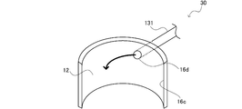
- FIG. 12 is a diagram showing a side wall 16c of the distributor 30 according to the third embodiment.
- the inflow pipe 131 is connected to the opening 16d provided on the upper side of the side wall 16c and communicates with the gas-liquid separation space 12 through the opening 16d.
- the gas-liquid refrigerant flowing in from the opening 16d spirally flows down toward the bottom surface 16b along the side wall 16c. Therefore, the disturbance of the gas-liquid interface 17 due to the inflow of the refrigerant can be reduced, and it is possible to avoid the generation of air bubbles in the liquid phase accumulated under the gas-liquid separation space 12.
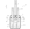
- FIG. 13 is an overall configuration diagram of the distributor 40 according to the fourth embodiment.
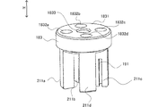
- FIG. 14 is a perspective view of the connection portion 183 and the first pipe 211 provided in the distributor 40 according to the fourth embodiment.
- FIG. 15 is a top view of the upper surface 1831 of the connecting portion 183.
- an opening 1833 extending in the vertical direction H is provided in the center of the connecting portion 183. It is provided.
- a collision portion 15 is inserted into the opening portion 1833.
- an insertion portion 15a corresponding to the shape of the opening 1833 is provided on the lower side of the collision portion 15, and the upper surface 15b of the collision portion 15 is formed by inserting the insertion portion 15a into the opening 1833. It is arranged on the connection portion 183.
- the upper surface 15b is a surface having an upwardly convex gradient.
- the upper surface 15b is provided, for example, in a conical shape or a quadrangular shape.
- the gas-liquid mixed refrigerant that has flowed downward from the inflow pipe 13 into the gas-liquid separation space 12 comes into contact with the upper surface 15b of the collision portion 15.
- the direction of the flow of the gas-liquid mixed refrigerant is changed from downward to the side wall 16c side, and flows down along the side wall 16c.
- the direction of the flow of the gas-liquid mixed refrigerant is changed from the downward direction to the side wall 16c side, so that the gas-liquid separation is promoted.
- the refrigerant falls down along the side wall 16c, it is possible to reduce the disturbance of the gas-liquid interface 17 and the generation of air bubbles. That is, the gas-liquid separation space 12 can be in a state in which the liquid and the gas are well separated.
- the opening 1833 does not have to penetrate. That is, the connecting portion 183 may have a recessed portion corresponding to the shape of the inserting portion 15a.
- the shape of the upper surface 15b of the collision portion 15 is not limited to the embodiment.
- the upper surface 15b may be a curved surface.
- the upper surface 15b may be a plane substantially parallel to the bottom surface 16b.
- the shape of the connecting portion 183 is not limited to the embodiment.
- the upper surface 1841 of the connecting portion 184 may be formed in a substantially square shape, and four openings 1842a to 1842d may be formed at positions corresponding to each apex of the square.
- a notch portion 1843 extending to the center of the upper surface 1841 may be formed on one side thereof.
- the collision portion 15 may be inserted at the center position of the substantially square of the connection portion 184 in the cutout portion 1843.
- the shape of the connecting portion 183 is not limited to the embodiment, and is not limited to the circle and the square. Further, in the central region of the connecting portion 184, the opening may be formed in a hole shape or a notch shape as long as it penetrates vertically. For example, in the circular connecting portion 183 as described with reference to FIG. 15 in the fourth embodiment, a notch portion extending from the outer circumference to the center may be formed instead of the opening portion 1833.
- FIG. 17 is an overall configuration diagram of the distributor 50 according to the fifth embodiment.
- the connecting portion 183 of the distributor 50 according to the fifth embodiment is the same as the connecting portion 183 according to the fourth embodiment, and has an opening 1833 in the center.
- the inflow pipe 13 is connected so that the refrigerant flows into the housing 11 from the lower part to the upper part of the housing 11.
- the inflow pipe 13 is provided so as to penetrate the bottom surface 16b and the connecting portion 183.
- the lower end 13b of the inflow pipe 13 is located below the housing 11, and the upper end 13a of the inflow pipe 13 is located between the connection portion 183 and the upper surface 16a in the housing 11.
- the gas-liquid mixed refrigerant that has flowed into the gas-liquid separation space 12 from the inflow pipe 13 comes into contact with the upper surface 16a of the housing 11 and the direction of flow is from upward to the side wall 16c side. It is changed and flows down along the side wall 16c. In this way, the direction of the flow is changed from the upward direction to the side wall 16c side, so that gas-liquid separation is promoted. Further, since the refrigerant falls down along the side wall 16c, it is possible to reduce the disturbance of the gas-liquid interface 17 and the generation of air bubbles. That is, the gas-liquid separation space 12 can be in a state in which the liquid and the gas are well separated. Further, the connection unit 183 can be shared with the connection unit 183 of the distributor 40 described in the fourth embodiment.
- FIG. 18 is an overall configuration diagram of the air conditioner 300 according to the sixth embodiment.
- the distributor according to any one of the first to fifth embodiments is applied to the air conditioner 300.
- the air conditioner 300 includes an indoor unit 310 and an outdoor unit 320.
- the indoor unit 310 and the outdoor unit 320 are connected by a liquid pipe 331 and a gas pipe 332 to form a refrigeration cycle.
- the indoor unit 310 includes an indoor heat exchanger 311, an indoor blower 312, and an indoor expansion valve 313.
- An indoor distributor 314 is provided between the indoor expansion valve 313 and the indoor heat exchanger 311.
- the outdoor unit 320 includes an outdoor heat exchanger 321, an outdoor blower 322, a compressor 323, a four-way valve 324, and an outdoor expansion valve 325.
- An outdoor distributor 326 is provided between the outdoor expansion valve 325 and the outdoor heat exchanger 321.
- the indoor distributor 314 and the outdoor distributor 326 are any of the distributors 10, 20, 30, 40, and 50 described in the first to fifth embodiments.
- the refrigerant 341 that has become hot and high pressure in the compressor 323 is guided to the indoor heat exchanger 311 (condenser) in the indoor unit 310 via the four-way valve 324. Then, the high-temperature refrigerant flowing through the indoor heat exchanger 311 dissipates heat to the indoor air supplied from the indoor blower 312, thereby warming the room. At this time, the gas refrigerant that has been deprived of heat gradually liquefies in the indoor heat exchanger 311, and the overcooled liquid refrigerant flows out from the outlet of the indoor heat exchanger 311 via the indoor distributor 314. do.
- the liquid refrigerant flowing out from the indoor unit 310 via the indoor expansion valve 313 becomes a gas-liquid two-phase refrigerant in a low temperature / low pressure state due to the expansion action when passing through the outdoor expansion valve 325.
- the low-temperature / low-pressure gas-liquid two-phase refrigerant is distributed by the outdoor distributor 326 and guided to a plurality of flow paths of the outdoor heat exchanger 321 (evaporator). Then, the low-temperature refrigerant flowing through the outdoor heat exchanger 321 absorbs heat from the outside air supplied from the outdoor blower 322. At the outlet of the outdoor heat exchanger 321 the refrigerant gasifies and returns to the compressor 323.
- the heating operation of the air conditioner 300 is realized by a series of refrigeration cycles in which the refrigerant 341 circulates counterclockwise as described above.
- the four-way valve 324 is switched to form a refrigeration cycle in which the refrigerant 341 circulates clockwise.
- the indoor heat exchanger 311 acts as an evaporator and the outdoor heat exchanger 321 acts as a condenser.
- FIG. 19 is an overall configuration diagram of the refrigerator 400 according to the seventh embodiment.
- the distributor according to any one of the first to fifth embodiments is applied to the refrigerator 400.
- a refrigerating cycle is composed of a compressor 401, a condenser 402, an expansion valve 403, a distributor 404, and an evaporator 405.
- the distributor 404 is any of the distributors 10, 20, 30, 40, and 50 described in the first to fifth embodiments.
- the refrigerant that has become hot and high pressure in the compressor 401 is condensed in the condenser 402 to become a liquid refrigerant.
- the low-temperature low-pressure liquid refrigerant decompressed by the expansion valve 403 is distributed to a plurality of flow paths by the distributor 404 and then supplied to the evaporator 405.
- the evaporator 405 heat is exchanged to become a gas refrigerant and return to the compressor 401.
- the cooler 406 cools the condenser 402 by flowing cooling water through the condenser 402.
Abstract
[Problem] An objective of the present invention is to distribute a refrigerant at an appropriate liquid refrigerant flow ratio. [Solution] The present invention is provided with a heat exchanger having a plurality of flow paths for a refrigerant, and a distributor which distributes the refrigerant to the flow paths of the heat exchanger, wherein: the distributor has an inflow pipe through which the refrigerant flows into a housing of the distributor, and a plurality of outflow pipes through which the refrigerant in the housing flows out; and each of the plurality of outflow pipes has a first pipe, which has a first opening in which the proportions of a gas refrigerant and a liquid refrigerant flowing out therefrom changes in accordance with the height of a gas-liquid interface in the housing, a second pipe which extends from inside the housing to outside the housing, and a connection section which connects the first pipe and the second pipe.
Description
本発明は、空気調和機、冷凍機及び分配器に関する。
The present invention relates to an air conditioner, a refrigerator and a distributor.
冷暖房に対応した空気調和機の多くでは、円形銅製伝熱管とアルミ製の短冊状のフィンで構成されるクロスフィンチューブ型熱交換器が用いられている。この熱交換器は、銅製伝熱管内にフロン系の冷媒を流動させることで、冷媒と空気の間で熱交換を行う。
Most air conditioners that support air conditioning use a cross-fin tube type heat exchanger that consists of a circular copper heat transfer tube and aluminum strip-shaped fins. This heat exchanger exchanges heat between the refrigerant and air by flowing a fluorocarbon-based refrigerant in a copper heat transfer tube.
一方、自動車用ラジエータや冷房専用のエアコンでは、小型軽量化、高性能化、低コスト化を目的として、パラレルフロー型の熱交換器が利用されている。この熱交換器は、外表面にアルミ製フィンをろう付けした複数の扁平伝熱管の両端の開口部に2本のヘッダ管が設けられ、流入側のヘッダ管から流出側のヘッダ管に冷媒を流動させるものである。
On the other hand, in radiators for automobiles and air conditioners dedicated to air conditioning, parallel flow type heat exchangers are used for the purpose of reducing size, weight, performance, and cost. In this heat exchanger, two header tubes are provided at the openings at both ends of a plurality of flat heat transfer tubes with aluminum fins brazed on the outer surface, and refrigerant is supplied from the inflow side header tube to the outflow side header tube. It is to be fluidized.
熱交換器を有効に利用すべく、熱交換器を構成する各伝熱管に流れる気液二相冷媒量を適正化できる分配器が望まれている。これに対し、特許文献1には、気液混合部に開口部を設けた複数の連通管を設けることで、分配器下流の冷媒回路の熱負荷に合わせた分配を行う分配器が開示されている。また、特許文献2には、流入管と、流出管と、底部に配置された仕切板と、を備えた冷媒分流器が開示されている。この冷媒分流器では、気液混合冷媒を、一旦液冷媒とガス冷媒に分離した後で、それぞれを合流させることにより、分配精度を向上させている。
In order to make effective use of the heat exchanger, a distributor capable of optimizing the amount of gas-liquid two-phase refrigerant flowing through each heat transfer tube constituting the heat exchanger is desired. On the other hand, Patent Document 1 discloses a distributor that distributes according to the heat load of the refrigerant circuit downstream of the distributor by providing a plurality of communication pipes having an opening in the gas-liquid mixing portion. There is. Further, Patent Document 2 discloses a refrigerant shunt including an inflow pipe, an outflow pipe, and a partition plate arranged at the bottom. In this refrigerant shunt, the distribution accuracy is improved by separating the gas-liquid mixed refrigerant into a liquid refrigerant and a gas refrigerant and then merging them.
しかしながら、低負荷条件や中負荷条件においては、冷媒の流れが緩やかになり、液とガスが分離して配管を流れることになる。特許文献1の技術では、この状態のまま冷媒を分配することになるため、ある流路においては液の比率が高く、他の流路ではガスの比率が高い、というように、適切な液冷媒流量比で冷媒を分配することができないという問題がある。
However, under low load conditions and medium load conditions, the flow of the refrigerant becomes slow, and the liquid and gas separate and flow through the piping. In the technique of Patent Document 1, since the refrigerant is distributed in this state, the ratio of the liquid is high in one flow path and the ratio of the gas is high in the other flow path. There is a problem that the refrigerant cannot be distributed by the flow rate ratio.
また、特許文献2の技術においては、気液を分離させた上で気液混合冷媒を流出管から吸い上げるが、流出管が液冷媒を吸い上げるためには、流入口から分配器に流入した液冷媒が仕切板を超えて流出管の下方まで流れ込む必要がある。すなわち、ある程度の液冷媒が分配器内に蓄えられていない状態においては、液冷媒が仕切板を超えることができず、したがって、適切な液冷媒流量比で熱交換器の各流路に分配することが困難であるという問題がある。このように、従来技術においては、適切な液冷媒流量比で冷媒を分配することができない場合があるという問題があった。
Further, in the technique of Patent Document 2, the gas-liquid mixed refrigerant is sucked up from the outflow pipe after separating the gas and liquid, but in order for the outflow pipe to suck up the liquid refrigerant, the liquid refrigerant flowing into the distributor from the inflow port Needs to flow beyond the divider to below the outflow pipe. That is, in a state where a certain amount of liquid refrigerant is not stored in the distributor, the liquid refrigerant cannot exceed the partition plate, and therefore, the liquid refrigerant is distributed to each flow path of the heat exchanger at an appropriate liquid refrigerant flow rate ratio. There is a problem that it is difficult. As described above, in the prior art, there is a problem that the refrigerant may not be distributed at an appropriate liquid refrigerant flow rate ratio.
本発明はこのような問題点に鑑みなされたもので、適切な液冷媒流量比で冷媒を分配することを目的とする。
The present invention has been made in view of such problems, and an object of the present invention is to distribute a refrigerant at an appropriate liquid refrigerant flow rate ratio.
本発明は、空気調和機であって、冷媒の複数の流路を有する熱交換器と、前記熱交換器の各流路に冷媒を分配する分配器とを備え、前記分配器は、前記分配器の筐体内へ冷媒を流入させる流入管と、前記筐体内の冷媒を流出させる複数の流出管とを有し、前記複数の流出管それぞれは、前記筐体内における気液界面の高さに応じて流出するガス冷媒及び液冷媒の割合が変わる第1の開口部を有する第1の配管と、前記筐体内から前記筐体外へ延びる第2の配管と、前記第1の配管と前記第2の配管を接続する接続部とを有する。
The present invention is an air conditioner, comprising a heat exchanger having a plurality of flow paths of the refrigerant and a distributor for distributing the refrigerant to each flow path of the heat exchanger, and the distributor is the distributor. It has an inflow pipe for inflowing refrigerant into the housing of the vessel and a plurality of outflow pipes for flowing out the refrigerant in the housing, and each of the plurality of outflow pipes corresponds to the height of the gas-liquid interface in the housing. A first pipe having a first opening in which the ratio of the gas refrigerant and the liquid refrigerant flowing out is changed, a second pipe extending from the inside of the housing to the outside of the housing, the first pipe and the second pipe. It has a connecting part for connecting pipes.
本発明の他の形態は、冷凍機であって、冷媒の複数の流路を有する熱交換器と、前記熱交換器の各流路に冷媒を分配する分配器とを備え、前記分配器は、前記分配器の筐体内へ冷媒を流入させる流入管と、前記筐体内の冷媒を流出させる複数の流出管とを有し、前記複数の流出管それぞれは、前記筐体内における気液界面の高さに応じて流出するガス冷媒及び液冷媒の割合が変わる第1の開口部を有する第1の配管と、前記筐体内から前記筐体外へ延びる第2の配管と、前記第1の配管と前記第2の配管を接続する接続部とを有する。
Another embodiment of the present invention is a refrigerator, comprising a heat exchanger having a plurality of flow paths of the refrigerant and a distributor for distributing the refrigerant to each flow path of the heat exchanger. The distributor has an inflow pipe for flowing the refrigerant into the housing and a plurality of outflow pipes for discharging the refrigerant in the housing, and each of the plurality of outflow pipes has a high gas-liquid interface in the housing. A first pipe having a first opening in which the ratio of the gas refrigerant and the liquid refrigerant flowing out correspondingly changes, a second pipe extending from the inside of the housing to the outside of the housing, the first pipe and the above. It has a connecting portion for connecting the second pipe.
本発明の他の形態は、熱交換器の各流路に冷媒を分配する分配器であって、前記分配器の筐体内へ冷媒を流入させる流入管と、前記筐体内の冷媒を流出させる複数の流出管とを有し、前記複数の流出管それぞれは、前記筐体内における気液界面の高さに応じて流出するガス冷媒及び液冷媒の割合が変わる第1の開口部を有する第1の配管と、前記筐体内から前記筐体外へ延びる第2の配管と、前記第1の配管と前記第2の配管を接続する接続部とを有する。
Another embodiment of the present invention is a distributor that distributes the liquid to each flow path of the heat exchanger, and has an inflow pipe that allows the liquid to flow into the housing of the distributor and a plurality of pipes that discharge the liquid from the housing. Each of the plurality of outflow pipes has a first opening in which the ratio of the outflow gas refrigerant and the liquid refrigerant changes according to the height of the gas-liquid interface in the housing. It has a pipe, a second pipe extending from the inside of the housing to the outside of the housing, and a connecting portion for connecting the first pipe and the second pipe.
本発明によれば、適切な液冷媒流量比で冷媒を分配することができる。
According to the present invention, the refrigerant can be distributed at an appropriate liquid refrigerant flow rate ratio.
(第1の実施形態)
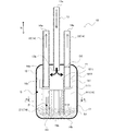
図1は、第1の実施形態に係る分配器10の全体構成図である。図2は、図1に示す分配器10のA-A線断面図である。分配器10は、冷凍サイクルにおいて熱交換器の複数の伝熱管に冷媒を分配する。本実施形態の分配器10は、パラレルフロー型の熱交換器及びフィンチューブ型の熱交換器のいずれに対しても適切な液冷媒流量比の冷媒を供給することができる。 (First Embodiment)
FIG. 1 is an overall configuration diagram of thedistributor 10 according to the first embodiment. FIG. 2 is a cross-sectional view taken along the line AA of the distributor 10 shown in FIG. The distributor 10 distributes the refrigerant to a plurality of heat transfer tubes of the heat exchanger in the refrigeration cycle. The distributor 10 of the present embodiment can supply a refrigerant having an appropriate liquid refrigerant flow ratio to both the parallel flow type heat exchanger and the fin tube type heat exchanger.
図1は、第1の実施形態に係る分配器10の全体構成図である。図2は、図1に示す分配器10のA-A線断面図である。分配器10は、冷凍サイクルにおいて熱交換器の複数の伝熱管に冷媒を分配する。本実施形態の分配器10は、パラレルフロー型の熱交換器及びフィンチューブ型の熱交換器のいずれに対しても適切な液冷媒流量比の冷媒を供給することができる。 (First Embodiment)
FIG. 1 is an overall configuration diagram of the
分配器10は、筐体11と、1本の流入管13と、4本の流出管14と、を有している。筐体161は、上下方向Hを長手方向とする略円筒状の筐体であり、上面16a、底面16b及び側壁16cを有している。流入管13及び流出管14は、分配器10の上下方向Hに沿って設けられている。さらに、流入管13及び流出管14は、筐体11の上面16aを貫通するように設けられている。すなわち、流入管13の上端13aは、筐体11の外側に位置し、流入管13の下端13bは筐体11の内部に位置する。同様に、流出管14の上端14aは、筐体11の外側に位置し、流出管14の下端14bは、筐体11の内部に位置する。流入管13は、分配器10の上面16a側(上部)から分配器10の内部の気液分離空間12に冷媒を流入させる。流出管14は、分配器10から冷媒を熱交換器に向けて流出する。
The distributor 10 has a housing 11, one inflow pipe 13, and four outflow pipes 14. The housing 161 is a substantially cylindrical housing having the vertical direction H as the longitudinal direction, and has an upper surface 16a, a lower surface 16b, and a side wall 16c. The inflow pipe 13 and the outflow pipe 14 are provided along the vertical direction H of the distributor 10. Further, the inflow pipe 13 and the outflow pipe 14 are provided so as to penetrate the upper surface 16a of the housing 11. That is, the upper end 13a of the inflow pipe 13 is located outside the housing 11, and the lower end 13b of the inflow pipe 13 is located inside the housing 11. Similarly, the upper end 14a of the outflow pipe 14 is located outside the housing 11, and the lower end 14b of the outflow pipe 14 is located inside the housing 11. The inflow pipe 13 allows the refrigerant to flow into the gas-liquid separation space 12 inside the distributor 10 from the upper surface 16a side (upper portion) of the distributor 10. The outflow pipe 14 causes the refrigerant to flow out from the distributor 10 toward the heat exchanger.
流出管14は、第1の配管211と、第2の配管22と、を有している。第1の配管211は底面16b側に位置し、第2の配管22は、第1の配管211の上部に接続し、筐体11の上面16aを貫通するように設けられている。第1の配管211と第2の配管22は、筐体11内において、接続部181により接続されている。接続部181は、流入管13の下端13bよりも下側に配置されている。さらに、接続部181は、第1の配管211の開口部191よりも上側、すなわち、第1の配管211の開口部191よりも流出管14における下流側に配置されている。
The outflow pipe 14 has a first pipe 211 and a second pipe 22. The first pipe 211 is located on the bottom surface 16b side, and the second pipe 22 is connected to the upper part of the first pipe 211 and is provided so as to penetrate the upper surface 16a of the housing 11. The first pipe 211 and the second pipe 22 are connected by a connecting portion 181 in the housing 11. The connecting portion 181 is arranged below the lower end 13b of the inflow pipe 13. Further, the connecting portion 181 is arranged above the opening 191 of the first pipe 211, that is, downstream of the opening 191 of the first pipe 211 in the outflow pipe 14.
図1及び図2に示すように、複数の第1の配管211a~211d(複数の流出管14)は、流入管13を囲うように配置されている。なお、図2においては、4本の第1の配管211を区別すべく、211a~212dとして示している。より具体的には、筐体11の横方向における中心位置に流入管13が配置され、4本の第1の配管211a~211dは、流入管13よりも側壁16c側に配置されている。さらに、第1の配管211a~211dそれぞれは、筐体11の中心位置を中心とした所定の円周上に等間隔に配置されている。ただし、各第1の配管211a~211dは、必ずしも等間隔に配置されていなくともよい。4本の第1の配管211a~211dに接続される4本の第2の配管22の配置は複数の第1の配管211a~211dの配置と同様である。すなわち、第2の配管22も、流入管13よりも側壁16c側において所定の円周上に等間隔に配置されている。
As shown in FIGS. 1 and 2, the plurality of first pipes 211a to 211d (plurality of outflow pipes 14) are arranged so as to surround the inflow pipe 13. In FIG. 2, the four first pipes 211 are shown as 211a to 212d in order to distinguish them. More specifically, the inflow pipe 13 is arranged at the center position in the lateral direction of the housing 11, and the four first pipes 211a to 211d are arranged on the side wall 16c side of the inflow pipe 13. Further, each of the first pipes 211a to 211d is arranged at equal intervals on a predetermined circumference centered on the center position of the housing 11. However, the first pipes 211a to 211d do not necessarily have to be arranged at equal intervals. The arrangement of the four second pipes 22 connected to the four first pipes 211a to 211d is the same as the arrangement of the plurality of first pipes 211a to 211d. That is, the second pipe 22 is also arranged at equal intervals on a predetermined circumference on the side wall 16c side of the inflow pipe 13.
図3は、接続部181及び第1の配管211の斜視図である。図4は、接続部181の上面1811を上から見た図である。図3に示すように、接続部181は、上下方向Hを高さ方向とする略円柱形状の部品であり、上部には、筐体11の径方向に延びる平面状の上面1811が設けられている。図1に示すように、上面1811は、上下方向Hに略垂直、すなわち、上面16a及び底面16bと略平行な面である。
FIG. 3 is a perspective view of the connection portion 181 and the first pipe 211. FIG. 4 is a top view of the upper surface 1811 of the connecting portion 181. As shown in FIG. 3, the connecting portion 181 is a substantially cylindrical component having the vertical direction H as the height direction, and a flat upper surface 1811 extending in the radial direction of the housing 11 is provided on the upper portion. There is. As shown in FIG. 1, the upper surface 1811 is a surface substantially perpendicular to the vertical direction H, that is, substantially parallel to the upper surface 16a and the bottom surface 16b.
さらに、図1に示すように、接続部181には、上面1811から下面まで貫通する開口部1812が形成されている。図3及び図4においては、接続部181に形成された4つの開口部1812を区別すべく1812a、1812b、1812c、1812dとして示している。図3及び図4に示すように4つの開口部1812a~1812dは、円状の上面1811において、所定の円周上に等間隔に配置されている。すなわち、4つの開口部1812a~1812dは、4本の流出管14の配置に対応した位置に設けられている。
Further, as shown in FIG. 1, the connecting portion 181 is formed with an opening 1812 penetrating from the upper surface 1811 to the lower surface. In FIGS. 3 and 4, the four openings 1812 formed in the connecting portion 181 are shown as 1812a, 1812b, 1812c, and 1812d to distinguish them. As shown in FIGS. 3 and 4, the four openings 1812a to 1812d are arranged at equal intervals on a predetermined circumference on the circular upper surface 1811. That is, the four openings 1812a to 1812d are provided at positions corresponding to the arrangement of the four outflow pipes 14.
さらに、図3に示すように、接続部181の下側には、4本の第1の配管211(211a~211d)それぞれの上端2111が接続されている。第1の配管211a~21dは、それぞれ接続部181の開口部1812a~1812dと繋がるように、ロウ付けなどにより接続部181に接続される。
Further, as shown in FIG. 3, the upper ends 2111 of each of the four first pipes 211 (211a to 211d) are connected to the lower side of the connecting portion 181. The first pipes 211a to 21d are connected to the connecting portion 181 by brazing or the like so as to be connected to the openings 1812a to 1812d of the connecting portion 181 respectively.
接続部181は、金属材料で製作されるものとする。また、他の例としては、接続部181は、樹脂等の材質で製作されてもよい。材質を樹脂とした場合には、冷凍サイクルに封入された冷媒による樹脂の変質が許容範囲であるものを使用することが望ましい。
The connection portion 181 shall be made of a metal material. Further, as another example, the connecting portion 181 may be made of a material such as resin. When the material is a resin, it is desirable to use a resin in which the deterioration of the resin by the refrigerant sealed in the refrigeration cycle is within an allowable range.
また、接続部181の加工方法としては、削り出しや3Dプリンタ等による積層構造(樹脂モールド品)が考えられる。樹脂モールド品の場合には、管表面に開口部を直接加工する方法に対して、開口部の向きや形状などのバリエーションを増やすことができる。
Further, as a processing method of the connection portion 181, a machined structure or a laminated structure (resin molded product) by a 3D printer or the like can be considered. In the case of a resin molded product, variations such as the orientation and shape of the opening can be increased as compared with the method of directly processing the opening on the pipe surface.
なお、他の例としては、少なくとも1つの第1の配管211は、接続部181と一体に形成されていてもよく、この場合には、第1の配管211も、接続部18と同様の材質で、一体に加工形成される。
As another example, at least one first pipe 211 may be formed integrally with the connection portion 181. In this case, the first pipe 211 is also made of the same material as the connection portion 18. Then, it is integrally processed and formed.
第1の配管211の内径は、D1であり、第2の配管22の内径は、D1よりも大きいD2である。接続部181の開口部1812a~1812dは、この内径の差に対応し、図4に示すように、接続部181の上面1811側の内径がD2、上面1811と反対側の面における内径がD1となっている。そして、開口部1812a~1812d内において、上面1811から上下方向Hにおいて所定の距離のところで、内径がD2からD1に狭くなっている。これにより、接続部181は、内径の異なる第1の配管211と第2の配管22とを接続することができる。
The inner diameter of the first pipe 211 is D1, and the inner diameter of the second pipe 22 is D2, which is larger than D1. The openings 1812a to 1812d of the connecting portion 181 correspond to this difference in inner diameter, and as shown in FIG. 4, the inner diameter of the connecting portion 181 on the upper surface 1811 side is D2, and the inner diameter on the surface opposite to the upper surface 1811 is D1. It has become. Then, in the openings 1812a to 1812d, the inner diameter is narrowed from D2 to D1 at a predetermined distance from the upper surface 1811 in the vertical direction H. As a result, the connecting portion 181 can connect the first pipe 211 and the second pipe 22 having different inner diameters.
また、第2の配管22は、開口部1812a~1812dに接続され、さらに筐体11の上面16aとロウ付けなどにより接続される。開口部1812a~1812dは、その内径が第2の配管22の外径よりもわずかに大きくなるように形成されている。このため、第2の配管22と開口部1812a~1812dとの接続において、第2の配管22の外壁と開口部1812a~1812dの内壁との間に隙間が形成される。このように、隙間が形成されることにより、第1の配管21が偏芯した状態で筐体11の上面16aに固定された場合であっても、これを吸収し、開口部1812aを介した第1の配管211と第2の配管22の接続を可能にすることができる。
Further, the second pipe 22 is connected to the openings 1812a to 1812d, and is further connected to the upper surface 16a of the housing 11 by brazing or the like. The openings 1812a to 1812d are formed so that the inner diameter thereof is slightly larger than the outer diameter of the second pipe 22. Therefore, in the connection between the second pipe 22 and the openings 1812a to 1812d, a gap is formed between the outer wall of the second pipe 22 and the inner wall of the openings 1812a to 1812d. By forming the gap in this way, even when the first pipe 21 is fixed to the upper surface 16a of the housing 11 in an eccentric state, it absorbs the gap and passes through the opening 1812a. It is possible to connect the first pipe 211 and the second pipe 22.
図5は、第1の配管211を示す図である。各第1の配管211a~211dには、流出管14(第1の配管211)の下端14bから上方向に延びた切り欠き形状の開口部191が設けられている。図2に示すように、開口部191は、いずれも分配器10の円周方向を向くように設けられている。このように、開口部191を下端14bから延びる形状にすることにより、加工を容易にすることができる。さらに、図1に示すように、開口部191は、開口部191の上下方向Hにおける中心位置Pが気液分離空間12の上下方向における中心位置Qよりも下側に位置するように設けられている。これにより、開口部191が気液分離空間12中の液相に届かず、ガス冷媒のみを吸い上げてしまうのを防ぐことができる。すなわち、開口部191から確実に液冷媒を吸い上げることができる。
FIG. 5 is a diagram showing the first pipe 211. Each of the first pipes 211a to 211d is provided with a notch-shaped opening 191 extending upward from the lower end 14b of the outflow pipe 14 (first pipe 211). As shown in FIG. 2, the openings 191 are all provided so as to face the circumferential direction of the distributor 10. In this way, by forming the opening 191 into a shape extending from the lower end 14b, processing can be facilitated. Further, as shown in FIG. 1, the opening 191 is provided so that the center position P in the vertical direction H of the opening 191 is located below the center position Q in the vertical direction of the gas-liquid separation space 12. There is. As a result, it is possible to prevent the opening 191 from reaching the liquid phase in the gas-liquid separation space 12 and sucking up only the gas refrigerant. That is, the liquid refrigerant can be reliably sucked up from the opening 191.
さらに、開口部191の中心位置P及びその長手方向の長さは、分配器10が使用される冷凍サイクルの能力から推定される気液界面17の高さに応じて設計されるのが好ましい。具体的には、開口部191の上端から下端の間に気液界面17が位置するような位置及び長さに開口部191を設けるのが好ましい。これにより、各流出管14から流出する冷媒の液冷媒流量比を適切に保つことができる。また、開口部191の横方向の幅は第1の配管211の円周の半分以下であるものとする。
Further, the central position P of the opening 191 and its longitudinal length are preferably designed according to the height of the gas-liquid interface 17 estimated from the capacity of the refrigeration cycle in which the distributor 10 is used. Specifically, it is preferable to provide the opening 191 at a position and length such that the gas-liquid interface 17 is located between the upper end and the lower end of the opening 191. As a result, the liquid-refrigerant flow rate ratio of the refrigerant flowing out from each outflow pipe 14 can be appropriately maintained. Further, it is assumed that the width of the opening 191 in the lateral direction is half or less of the circumference of the first pipe 211.
次に、分配器10における冷媒の流れについて説明する。分配器10は、その下方向が重力方向に対応するように設置される。このため、冷媒は、流入管13から重力方向に沿って筐体11に流入し、流出管14から重力方向と逆の方向に沿って流出する。流入管13の上端13aから下端13bへ流れることで、下向きに気液分離空間12に流入した気液混合冷媒は、接続部181の上面1811に接触する。これにより、気液混合冷媒の流れの向きが下向きから側壁16c側に変えられる。このように、上面1811は、気液混合冷媒が衝突し、流れの向きを変える衝突面として機能する。気液混合冷媒は、その後、側壁16cを伝って下方に流れ落ちる。このように、気液混合冷媒の流れが下向きから側壁16c側に変えられることで、気液分離が促進される。さらに、冷媒が側壁16cを伝って落ちるので、気液界面17が乱されたり、気泡が生じたりするのを低減することができる。すなわち、気液分離空間12を液体と気体とが良好に分離した状態とすることができる。
Next, the flow of the refrigerant in the distributor 10 will be described. The distributor 10 is installed so that its downward direction corresponds to the direction of gravity. Therefore, the refrigerant flows from the inflow pipe 13 into the housing 11 along the direction of gravity, and flows out from the outflow pipe 14 along the direction opposite to the direction of gravity. The gas-liquid mixed refrigerant that has flowed downward from the upper end 13a to the lower end 13b of the inflow pipe 13 and has flowed downward into the gas-liquid separation space 12 comes into contact with the upper surface 1811 of the connecting portion 181. As a result, the direction of the flow of the gas-liquid mixed refrigerant is changed from the downward direction to the side wall 16c side. In this way, the upper surface 1811 functions as a collision surface on which the gas-liquid mixed refrigerant collides and changes the direction of the flow. The gas-liquid mixed refrigerant then flows down along the side wall 16c. In this way, the flow of the gas-liquid mixed refrigerant is changed from the downward direction to the side wall 16c side, so that gas-liquid separation is promoted. Further, since the refrigerant falls down along the side wall 16c, it is possible to reduce the disturbance of the gas-liquid interface 17 and the generation of air bubbles. That is, the gas-liquid separation space 12 can be in a state in which the liquid and the gas are well separated.
第1の配管211(流出管14)の開口部191のうち、下側の領域は気液界面17の下側において液体と接触し、開口部191のうち上側の領域は気液界面17の上側においてガスと接触している。このため、流出管14からは適切な液冷媒流量比で液冷媒とガス冷媒が吸い上げられる。すなわち、本実施形態に係る分配器10は、熱交換器の各流路に、液冷媒流量比が適切な冷媒を供給することができる。さらに、気液界面17の上下変動に応じて、開口部191において、ガスが接触する面積と液体が接触する面積の比も変動する。換言すれば、開口部191から流出するガス冷媒及び液冷媒の割合(液冷媒流量比)は気液界面17の高さに応じて変わる。
The lower region of the opening 191 of the first pipe 211 (outflow pipe 14) is in contact with the liquid at the lower side of the gas-liquid interface 17, and the upper region of the opening 191 is the upper side of the gas-liquid interface 17. Is in contact with gas. Therefore, the liquid refrigerant and the gas refrigerant are sucked up from the outflow pipe 14 at an appropriate liquid refrigerant flow rate ratio. That is, the distributor 10 according to the present embodiment can supply a refrigerant having an appropriate liquid refrigerant flow rate ratio to each flow path of the heat exchanger. Further, the ratio of the area in contact with the gas to the area in contact with the liquid in the opening 191 also changes according to the vertical fluctuation of the gas-liquid interface 17. In other words, the ratio of the gas refrigerant and the liquid refrigerant flowing out from the opening 191 (liquid refrigerant flow ratio) changes according to the height of the gas-liquid interface 17.
以上のように、本実施形態に係る分配器10は、気液を分離させるので、中負荷条件や低負荷条件においても、気液分離空間12における液冷媒流量比に応じた適切な液冷媒流量比の冷媒を流出管14から熱交換器の各流路に流出させることができる。
As described above, since the distributor 10 according to the present embodiment separates the gas and liquid, an appropriate liquid-refrigerant flow rate according to the liquid-refrigerant flow rate ratio in the gas-liquid separation space 12 even under medium load conditions and low load conditions. The ratio refrigerant can be discharged from the outflow pipe 14 to each flow path of the heat exchanger.
従来技術において説明したように、特許文献2の技術においては、仕切板を超える量の液冷媒が分配器に溜まらないと、流出管に液冷媒が流入しない。これに対し、本実施形態の流出管14においては、開口部191は、流出管14の中心位置Pが気液分離空間12の中心位置Qよりも下に位置するよう、気液分離空間12の下方に設けられている。このため、気液分離空間12に存在する液冷媒の量が少ない状態においても、流出管14は、適切な量の液冷媒を吸い上げることができる。
As described in the prior art, in the technique of Patent Document 2, the liquid refrigerant does not flow into the outflow pipe unless the amount of the liquid refrigerant exceeding the partition plate is accumulated in the distributor. On the other hand, in the outflow pipe 14 of the present embodiment, the opening 191 is provided in the gas-liquid separation space 12 so that the center position P of the outflow pipe 14 is located below the center position Q of the gas-liquid separation space 12. It is provided below. Therefore, even when the amount of the liquid refrigerant existing in the gas-liquid separation space 12 is small, the outflow pipe 14 can suck up an appropriate amount of the liquid refrigerant.
また、上述のように、分配器10は、その下方向と重力方向が一致するように設置されるのが望ましいが、実際の設置状態においては、分配器10の下方向と重力方向はわずかにずれる。このように分配器10が傾いた状態においても、本実施形態の分配器10においては、複数の流出管14が等しい液冷媒流量比の冷媒を熱交換器の各流路に供給することができる。
Further, as described above, it is desirable that the distributor 10 is installed so that the downward direction thereof and the direction of gravity coincide with each other, but in the actual installation state, the downward direction of the distributor 10 and the direction of gravity are slightly different. It shifts. Even when the distributor 10 is tilted in this way, in the distributor 10 of the present embodiment, the plurality of outflow pipes 14 can supply the refrigerant having the same liquid refrigerant flow rate ratio to each flow path of the heat exchanger. ..
さらに、本実施形態の分配器10を組み立てる際には、まず第1の配管211と接続部181とを接続させ、その後、第2の配管22を筐体11の上面16aにロウ付けする。第2の配管22を筐体11の上面16aにロウ付けする際には、第1の配管211が接続部181と既に接続されている。したがって、ロウ付けの際には、接続部181と第2の配管22とが接合されていることを確認できればよく、気液界面17と開口部191の位置調整を容易にすることができる。すなわち、分配器10の組み立てを従来よりも容易にすることができる。
Further, when assembling the distributor 10 of the present embodiment, the first pipe 211 and the connecting portion 181 are first connected, and then the second pipe 22 is brazed to the upper surface 16a of the housing 11. When the second pipe 22 is brazed to the upper surface 16a of the housing 11, the first pipe 211 is already connected to the connection portion 181. Therefore, at the time of brazing, it is sufficient to confirm that the connecting portion 181 and the second pipe 22 are joined, and the positions of the gas-liquid interface 17 and the opening 191 can be easily adjusted. That is, the distributor 10 can be assembled more easily than before.
なお、第1の実施形態に係る分配器10の第1の変形例としては、流出管の数は、2本以上であればよく、実施形態に限定されるものではない。流出管の数が4本以下の場合には第1の実施形態において説明した接続部181を用いることができる。例えば、流出管の数が2本の場合には、接続部181の開口部1812a~1812dのうち、2つの開口部1812a,1812cにのみ流出管14を接続する。これにより、2分岐の分配器を構成することができる。このように、接続部181を共通部品とし、筐体11に取り付ける流出管の本数を調整することで、分岐数を自由に変更することができる。さらに、流出管の数は、6本や、8本以上であってもよい。この場合は、流出管の数に対応した開口部が形成された接続部を用いればよい。
As a first modification of the distributor 10 according to the first embodiment, the number of outflow pipes may be two or more, and is not limited to the embodiment. When the number of outflow pipes is 4 or less, the connection portion 181 described in the first embodiment can be used. For example, when the number of outflow pipes is two, the outflow pipe 14 is connected only to the two openings 1812a and 1812c of the openings 1812a to 1812d of the connection portion 181. As a result, a two-branch distributor can be configured. In this way, the number of branches can be freely changed by using the connecting portion 181 as a common component and adjusting the number of outflow pipes attached to the housing 11. Further, the number of outflow pipes may be 6 or 8 or more. In this case, a connecting portion having an opening corresponding to the number of outflow pipes may be used.
第2の変形例としては、第1の配管211の開口部191の形状は、実施形態に限定されるものではない。例えば、図6Aに示すように、第1の配管212には、開口部192として第1の配管211の長手方向、すなわち上下方向Hに延びた長穴が形成されていてもよい。この場合、流出管14の下端14bは閉じられていてもよく、開口していてもよい。また、例えば、図6Bに示すように、第1の配管213には、開口部193として、複数の穴193a~193gが形成されていてもよい。さらに、各穴193a~193gは円形であり、等間隔に設けられているものとする。この場合も、各穴193a~193gからガス冷媒及び液冷媒の少なくとも一方が流入し、複数の穴193a~193gで構成された開口部193における液冷媒流量比を各流出管14においてほぼ等しくすることができる。なお、この場合、開口部193の中心は、開口部193の全長Lの中間位置(L/2)とする。
As a second modification, the shape of the opening 191 of the first pipe 211 is not limited to the embodiment. For example, as shown in FIG. 6A, the first pipe 212 may be formed with an elongated hole extending in the longitudinal direction of the first pipe 211, that is, in the vertical direction H, as the opening 192. In this case, the lower end 14b of the outflow pipe 14 may be closed or may be open. Further, for example, as shown in FIG. 6B, a plurality of holes 193a to 193g may be formed as the opening 193 in the first pipe 213. Further, it is assumed that the holes 193a to 193g are circular and are provided at equal intervals. Also in this case, at least one of the gas refrigerant and the liquid refrigerant flows in from each of the holes 193a to 193g, and the liquid refrigerant flow rate ratio in the opening 193 composed of the plurality of holes 193a to 193g is made substantially equal in each outflow pipe 14. Can be done. In this case, the center of the opening 193 is an intermediate position (L / 2) of the total length L of the opening 193.
第3の変形例としては、複数の流出管14の開口部191の位置、サイズ及び形状は、互いに異なっていてもよい。例えば、熱交換器の各流路へ流出させる冷媒の液冷媒流量比を異ならせたい場合がある。このような場合には、要求される液冷媒流量比に応じて、複数の開口部191の位置及びサイズのうち少なくとも一方を制御してもよい。また、例えば、一の流出管14の開口部は長穴の形状であるのに対し、他の流出管14の開口部はスリット形状であってもよい。
As a third modification, the positions, sizes, and shapes of the openings 191 of the plurality of outflow pipes 14 may be different from each other. For example, it may be desired to make the liquid-refrigerant flow rate ratio of the refrigerant flowing out to each flow path of the heat exchanger different. In such a case, at least one of the positions and sizes of the plurality of openings 191 may be controlled according to the required liquid-refrigerant flow rate ratio. Further, for example, the opening of one outflow pipe 14 may have an elongated hole shape, while the opening of the other outflow pipe 14 may have a slit shape.
第4の変形例としては、接続部181の形状は、実施形態に限定されるものではない。例えば、図7に示すように、接続部182は、中央から各開口部1822a、1822b、1822c、1822dに延びる複数の片部1821a、1821b、1821c、1821dを有するような形状であってもよい。この場合も、流入管13から流入した冷媒は接続部182に接触し、流れの向きが下向きから側壁16c側に変えられる。
As a fourth modification, the shape of the connecting portion 181 is not limited to the embodiment. For example, as shown in FIG. 7, the connecting portion 182 may have a shape having a plurality of piece portions 1821a, 1821b, 1821c, 1821d extending from the center to the respective openings 1822a, 1822b, 1822c, 1822d. Also in this case, the refrigerant flowing in from the inflow pipe 13 comes into contact with the connection portion 182, and the direction of the flow is changed from the downward direction to the side wall 16c side.
第5の変形例としては、接続部181の上面1811は、筐体11の横方向に延びる平面でなくてもよい。例えば、上面1811は、上方向に凸の勾配を有する面であってもよい。上面1811は、例えば円錐形状や四角形状に設けられていてもよい。
As a fifth modification, the upper surface 1811 of the connecting portion 181 does not have to be a flat surface extending in the lateral direction of the housing 11. For example, the upper surface 1811 may be a surface having an upwardly convex gradient. The upper surface 1811 may be provided, for example, in a conical shape or a quadrangular shape.
図8は、第6の変形例に係る分配器10の概略断面図である。第6の変形例としては、第1の配管211のうち、開口部191の上の側壁に張出部60が形成されていてもよい。張出部60は、第1の配管211の径方向の外側に向かって張り出している。張出部60は、底面16bと略平行な平面である。気液界面17は冷凍サイクルの運転条件によって変化するが、張出部60が気液界面17の近傍に設けられていることにより、液面の波立ちを抑制し、開口部191からの冷媒の流出を安定させることができる。
FIG. 8 is a schematic cross-sectional view of the distributor 10 according to the sixth modification. As a sixth modification, the overhanging portion 60 may be formed on the side wall above the opening 191 in the first pipe 211. The overhanging portion 60 projects outward in the radial direction of the first pipe 211. The overhanging portion 60 is a plane substantially parallel to the bottom surface 16b. The gas-liquid interface 17 changes depending on the operating conditions of the refrigeration cycle, but since the overhanging portion 60 is provided in the vicinity of the gas-liquid interface 17, rippling of the liquid surface is suppressed and the refrigerant flows out from the opening 191. Can be stabilized.
第7の変形例としては、第1の配管211と第2の配管22の径の大きさの関係は実施形態に限定されるものではない。すなわち、第1の配管211の径D1と第2の配管22の径D2は等しくてもよく、第1の配管211の径D1が第2の配管22の径D2よりも大きくてもよい。
As a seventh modification, the relationship between the diameters of the first pipe 211 and the second pipe 22 is not limited to the embodiment. That is, the diameter D1 of the first pipe 211 and the diameter D2 of the second pipe 22 may be equal, and the diameter D1 of the first pipe 211 may be larger than the diameter D2 of the second pipe 22.
(第2の実施形態)
次に、第2の実施形態に係る分配器20について、第1の実施形態に係る分配器10と異なる点を主に説明する。図9は、第2の実施形態に係る分配器20の概略断面図である。図10は、図9に示す分配器20のB-B線断面図である。筐体11の底面16bに溝70が形成されている。図10に示すように、底面16bの円の半径方向において、側壁16c側の端(外端70a)から内側の端(内端70b)までが窪みとなり、環状の溝70が設けられている。ここで、溝70は、窪み部の一例である。溝70の半径方向の幅、すなわち外端70aから内端70bまでの距離は、第1の配管211の外径よりも大きい。そして、4本の第1の配管211の下端14bは、溝70内に位置する。このように、溝70が形成され、溝70内に第1の配管211の下端14bが位置するように配置することにより、第1の配管211の位置決めを容易にし、分配器20の組み立て性を良好にすることができる。さらに、窪み部を環状の1つの溝70として形成することにより、加工を容易とすることができ、また第1の配管211を窪み部内に位置させる調整を容易とすることができる。また、第1の配管211の下端14bは、溝70内の底面70cに接しているものとする。ただし、下端14bは、溝70内に位置していればよく、底面70cに接していなくともよい。 (Second Embodiment)
Next, thedistributor 20 according to the second embodiment will be mainly described as being different from the distributor 10 according to the first embodiment. FIG. 9 is a schematic cross-sectional view of the distributor 20 according to the second embodiment. FIG. 10 is a cross-sectional view taken along the line BB of the distributor 20 shown in FIG. A groove 70 is formed on the bottom surface 16b of the housing 11. As shown in FIG. 10, in the radial direction of the circle of the bottom surface 16b, a recess is formed from the end (outer end 70a) on the side wall 16c side to the inner end (inner end 70b), and an annular groove 70 is provided. Here, the groove 70 is an example of a recessed portion. The radial width of the groove 70, that is, the distance from the outer end 70a to the inner end 70b is larger than the outer diameter of the first pipe 211. The lower ends 14b of the four first pipes 211 are located in the grooves 70. By forming the groove 70 and arranging the lower end 14b of the first pipe 211 so as to be located in the groove 70 in this way, the positioning of the first pipe 211 is facilitated and the assembleability of the distributor 20 is improved. Can be good. Further, by forming the recessed portion as one annular groove 70, processing can be facilitated, and adjustment for locating the first pipe 211 in the recessed portion can be facilitated. Further, it is assumed that the lower end 14b of the first pipe 211 is in contact with the bottom surface 70c in the groove 70. However, the lower end 14b may be located in the groove 70 and may not be in contact with the bottom surface 70c.
次に、第2の実施形態に係る分配器20について、第1の実施形態に係る分配器10と異なる点を主に説明する。図9は、第2の実施形態に係る分配器20の概略断面図である。図10は、図9に示す分配器20のB-B線断面図である。筐体11の底面16bに溝70が形成されている。図10に示すように、底面16bの円の半径方向において、側壁16c側の端(外端70a)から内側の端(内端70b)までが窪みとなり、環状の溝70が設けられている。ここで、溝70は、窪み部の一例である。溝70の半径方向の幅、すなわち外端70aから内端70bまでの距離は、第1の配管211の外径よりも大きい。そして、4本の第1の配管211の下端14bは、溝70内に位置する。このように、溝70が形成され、溝70内に第1の配管211の下端14bが位置するように配置することにより、第1の配管211の位置決めを容易にし、分配器20の組み立て性を良好にすることができる。さらに、窪み部を環状の1つの溝70として形成することにより、加工を容易とすることができ、また第1の配管211を窪み部内に位置させる調整を容易とすることができる。また、第1の配管211の下端14bは、溝70内の底面70cに接しているものとする。ただし、下端14bは、溝70内に位置していればよく、底面70cに接していなくともよい。 (Second Embodiment)
Next, the
第2の実施形態の第1の変形例としては、筐体11の底面16bのうち、流出管14の下端14bが位置する領域に窪みが形成されていればよく、その形状は、環状の溝70に限定されるものではない。他の例としては、底面16bのうち、流出管14の下端14bが位置する4か所に、円形の4つの窪み部が形成されてもよい。
As a first modification of the second embodiment, it is sufficient that a recess is formed in the region of the bottom surface 16b of the housing 11 where the lower end 14b of the outflow pipe 14 is located, and the shape is an annular groove. It is not limited to 70. As another example, four circular recesses may be formed at four locations on the bottom surface 16b where the lower end 14b of the outflow pipe 14 is located.
図11は、第2の変形例に係る分配器20の概略断面図である。第2の変形例としては、溝70内に突起部80が形成されていてもよい。突起部80は、流出管14の下端14bが位置する位置に配置される。これにより、第1の配管211の内側(管内)に突起部80の少なくとも一部が位置することになるため、第1の配管211の横方向の動きが制限される。すなわち、第1の配管211の、筐体11の底面16bへの設置を安定化させることができる。なお、第1の配管211の下端14bは開口していることとしたが、他の例としては、第1の配管211の下端14bは閉じられていてもよい。閉じられている場合には、下端14bには、突起部80に対応した窪み部が形成されているものとする。これにより、閉じられている場合においても、突起部80が窪み部内に挿入されることで、第1の配管211の横方向の動きが制限され、第1の配管211の設置を安定化させることができる。
FIG. 11 is a schematic cross-sectional view of the distributor 20 according to the second modification. As a second modification, the protrusion 80 may be formed in the groove 70. The protrusion 80 is arranged at a position where the lower end 14b of the outflow pipe 14 is located. As a result, at least a part of the protrusion 80 is located inside (inside the pipe) of the first pipe 211, so that the lateral movement of the first pipe 211 is restricted. That is, the installation of the first pipe 211 on the bottom surface 16b of the housing 11 can be stabilized. The lower end 14b of the first pipe 211 is open, but as another example, the lower end 14b of the first pipe 211 may be closed. When closed, it is assumed that a recess corresponding to the protrusion 80 is formed at the lower end 14b. As a result, even when the protrusion 80 is inserted into the recess, the lateral movement of the first pipe 211 is restricted, and the installation of the first pipe 211 is stabilized. Can be done.
(第3の実施形態)
次に、第3の実施形態に係る分配器30について、他の実施形態に係る分配器と異なる点を主に説明する。図12は、第3の実施形態に係る分配器30の側壁16cを示す図である。第3の実施形態に係る分配器30においては、流入管131は、側壁16cの上側に設けられた開口部16dに接続され、開口部16dを通じて、気液分離空間12と連通している。 (Third Embodiment)
Next, thedistributor 30 according to the third embodiment will be mainly described as being different from the distributor according to the other embodiments. FIG. 12 is a diagram showing a side wall 16c of the distributor 30 according to the third embodiment. In the distributor 30 according to the third embodiment, the inflow pipe 131 is connected to the opening 16d provided on the upper side of the side wall 16c and communicates with the gas-liquid separation space 12 through the opening 16d.
次に、第3の実施形態に係る分配器30について、他の実施形態に係る分配器と異なる点を主に説明する。図12は、第3の実施形態に係る分配器30の側壁16cを示す図である。第3の実施形態に係る分配器30においては、流入管131は、側壁16cの上側に設けられた開口部16dに接続され、開口部16dを通じて、気液分離空間12と連通している。 (Third Embodiment)
Next, the
開口部16dから流入した気液冷媒は、側壁16cに沿って底面16bに向けてらせん状に流れ落ちる。このため、冷媒流入による気液界面17の乱れを低減でき、気液分離空間12の下に溜まった液相中に気泡が生じるのを避けることができる。
The gas-liquid refrigerant flowing in from the opening 16d spirally flows down toward the bottom surface 16b along the side wall 16c. Therefore, the disturbance of the gas-liquid interface 17 due to the inflow of the refrigerant can be reduced, and it is possible to avoid the generation of air bubbles in the liquid phase accumulated under the gas-liquid separation space 12.
(第4の実施形態)
次に、第4の実施気体に係る分配器40について、他の実施形態に係る分配器と異なる点を主に説明する。図13は、第4の実施形態に係る分配器40の全体構成図である。図14は、第4の実施形態に係る分配器40に設けられた接続部183及び第1の配管211の斜視図である。図15は、接続部183の上面1831を上から見た図である。第4の実施形態に係る分配器40においては、接続部183には、流出管14に対応した4つの開口部1832a~1832dの他、接続部183の中央に上下方向Hに延びる開口部1833が設けられている。開口部1833には、衝突部15が挿入されている。具体的には、衝突部15の下側に開口部1833の形状に対応した挿入部15aが設けられており、挿入部15aが開口部1833に挿入されることで、衝突部15の上面15bが接続部183の上に配置される。上面15bは、上方向に凸の勾配を有する面である。上面15bは、例えば円錐形状や四角形状に設けられているものとする。 (Fourth Embodiment)
Next, thedistributor 40 according to the fourth embodiment will be mainly described as being different from the distributor according to the other embodiments. FIG. 13 is an overall configuration diagram of the distributor 40 according to the fourth embodiment. FIG. 14 is a perspective view of the connection portion 183 and the first pipe 211 provided in the distributor 40 according to the fourth embodiment. FIG. 15 is a top view of the upper surface 1831 of the connecting portion 183. In the distributor 40 according to the fourth embodiment, in the connecting portion 183, in addition to the four openings 1832a to 1832d corresponding to the outflow pipe 14, an opening 1833 extending in the vertical direction H is provided in the center of the connecting portion 183. It is provided. A collision portion 15 is inserted into the opening portion 1833. Specifically, an insertion portion 15a corresponding to the shape of the opening 1833 is provided on the lower side of the collision portion 15, and the upper surface 15b of the collision portion 15 is formed by inserting the insertion portion 15a into the opening 1833. It is arranged on the connection portion 183. The upper surface 15b is a surface having an upwardly convex gradient. The upper surface 15b is provided, for example, in a conical shape or a quadrangular shape.
次に、第4の実施気体に係る分配器40について、他の実施形態に係る分配器と異なる点を主に説明する。図13は、第4の実施形態に係る分配器40の全体構成図である。図14は、第4の実施形態に係る分配器40に設けられた接続部183及び第1の配管211の斜視図である。図15は、接続部183の上面1831を上から見た図である。第4の実施形態に係る分配器40においては、接続部183には、流出管14に対応した4つの開口部1832a~1832dの他、接続部183の中央に上下方向Hに延びる開口部1833が設けられている。開口部1833には、衝突部15が挿入されている。具体的には、衝突部15の下側に開口部1833の形状に対応した挿入部15aが設けられており、挿入部15aが開口部1833に挿入されることで、衝突部15の上面15bが接続部183の上に配置される。上面15bは、上方向に凸の勾配を有する面である。上面15bは、例えば円錐形状や四角形状に設けられているものとする。 (Fourth Embodiment)
Next, the
このような構成により、第4の実施形態の分配器40においては、流入管13から下向きに気液分離空間12に流入した気液混合冷媒は、衝突部15の上面15bに接触する。これにより、気液混合冷媒の流れの向きが下向きから側壁16c側に変えられ、側壁16cを伝って下方に流れ落ちる。このように、気液混合冷媒の流れの向きが下向きから側壁16c側に変えられることで、気液分離が促進される。さらに、冷媒が側壁16cを伝って落ちるので、気液界面17が乱されたり、気泡が生じたりするのを低減することができる。すなわち、気液分離空間12を液体と気体とが良好に分離した状態とすることができる。
With such a configuration, in the distributor 40 of the fourth embodiment, the gas-liquid mixed refrigerant that has flowed downward from the inflow pipe 13 into the gas-liquid separation space 12 comes into contact with the upper surface 15b of the collision portion 15. As a result, the direction of the flow of the gas-liquid mixed refrigerant is changed from downward to the side wall 16c side, and flows down along the side wall 16c. In this way, the direction of the flow of the gas-liquid mixed refrigerant is changed from the downward direction to the side wall 16c side, so that the gas-liquid separation is promoted. Further, since the refrigerant falls down along the side wall 16c, it is possible to reduce the disturbance of the gas-liquid interface 17 and the generation of air bubbles. That is, the gas-liquid separation space 12 can be in a state in which the liquid and the gas are well separated.
第4の実施形態の第1の変形例としては、開口部1833は貫通していなくともよい。すなわち、接続部183は、挿入部15aの形状に対応した、窪み部を有してもよい。
As a first modification of the fourth embodiment, the opening 1833 does not have to penetrate. That is, the connecting portion 183 may have a recessed portion corresponding to the shape of the inserting portion 15a.
第2の変形例としては、衝突部15の上面15bの形状は、実施形態に限定されるものではない。他の例としては、上面15bは、曲面であってもよい。また他の例としては、上面15bは、底面16bに略平行な平面であってもよい。
As a second modification, the shape of the upper surface 15b of the collision portion 15 is not limited to the embodiment. As another example, the upper surface 15b may be a curved surface. As another example, the upper surface 15b may be a plane substantially parallel to the bottom surface 16b.
第3の変形例としては、接続部183の形状は実施形態に限定されるものではない。例えば、図16に示すように、接続部184は、上面1841が略正方形の形状に形成され、正方形の各頂点に対応した位置に4つの開口部1842a~1842dが形成されてもよい。さらに、その一辺に、上面1841の中心まで延びる切り欠き部1843が形成されていてもよい。この場合には、切り欠き部1843のうち、接続部184の略正方形の中心位置に衝突部15が挿入されればよい。
As a third modification, the shape of the connecting portion 183 is not limited to the embodiment. For example, as shown in FIG. 16, the upper surface 1841 of the connecting portion 184 may be formed in a substantially square shape, and four openings 1842a to 1842d may be formed at positions corresponding to each apex of the square. Further, a notch portion 1843 extending to the center of the upper surface 1841 may be formed on one side thereof. In this case, the collision portion 15 may be inserted at the center position of the substantially square of the connection portion 184 in the cutout portion 1843.
このように、接続部183の形状は実施形態に限定されるものではなく、円形及び正方形に限定されるものではない。また、接続部184の中央の領域において、上下に貫通していればよく、そのための開口部は、穴状に形成されてもよく、切り欠き形状に形成されてもよい。例えば、第4の実施形態において図15を参照しつつ説明したような円形の接続部183において、開口部1833に変えて、外周から中心に伸びる切り欠き部が形成されてもよい。
As described above, the shape of the connecting portion 183 is not limited to the embodiment, and is not limited to the circle and the square. Further, in the central region of the connecting portion 184, the opening may be formed in a hole shape or a notch shape as long as it penetrates vertically. For example, in the circular connecting portion 183 as described with reference to FIG. 15 in the fourth embodiment, a notch portion extending from the outer circumference to the center may be formed instead of the opening portion 1833.
(第5の実施形態)
次に、第5の実施形態に係る分配器50について、他の実施形態に係る分配器と異なる点を主に説明する。図17は、第5の実施形態に係る分配器50の全体構成図である。第5の実施形態に係る分配器50の接続部183は、第4の実施形態に係る接続部183と同様であり、中央に開口部1833を有している。さらに、第4の実施形態においては、流入管13は、筐体11の下部から上に向けて筐体11内に冷媒が流入するように接続されている。具体的には、流入管13は、底面16b及び接続部183を貫通するように設けられている。そして、流入管13の下端13bは、筐体11の下側に位置し、流入管13の上端13aは、筐体11内において、接続部183と上面16aの間に位置する。 (Fifth Embodiment)
Next, thedistributor 50 according to the fifth embodiment will be mainly described as being different from the distributor according to the other embodiments. FIG. 17 is an overall configuration diagram of the distributor 50 according to the fifth embodiment. The connecting portion 183 of the distributor 50 according to the fifth embodiment is the same as the connecting portion 183 according to the fourth embodiment, and has an opening 1833 in the center. Further, in the fourth embodiment, the inflow pipe 13 is connected so that the refrigerant flows into the housing 11 from the lower part to the upper part of the housing 11. Specifically, the inflow pipe 13 is provided so as to penetrate the bottom surface 16b and the connecting portion 183. The lower end 13b of the inflow pipe 13 is located below the housing 11, and the upper end 13a of the inflow pipe 13 is located between the connection portion 183 and the upper surface 16a in the housing 11.
次に、第5の実施形態に係る分配器50について、他の実施形態に係る分配器と異なる点を主に説明する。図17は、第5の実施形態に係る分配器50の全体構成図である。第5の実施形態に係る分配器50の接続部183は、第4の実施形態に係る接続部183と同様であり、中央に開口部1833を有している。さらに、第4の実施形態においては、流入管13は、筐体11の下部から上に向けて筐体11内に冷媒が流入するように接続されている。具体的には、流入管13は、底面16b及び接続部183を貫通するように設けられている。そして、流入管13の下端13bは、筐体11の下側に位置し、流入管13の上端13aは、筐体11内において、接続部183と上面16aの間に位置する。 (Fifth Embodiment)
Next, the
このような構成により、本実施形態においては、流入管13から気液分離空間12に流入した気液混合冷媒は、筐体11の上面16aと接触して流れの向きは上向きから側壁16c側に変えられ、側壁16cを伝って下方に流れ落ちる。このように、流れの向きが上向きから側壁16c側に変えられることで、気液分離が促進される。さらに、冷媒が側壁16cを伝って落ちるので、気液界面17が乱されたり、気泡が生じたりするのを低減することができる。すなわち、気液分離空間12を液体と気体とが良好に分離した状態とすることができる。さらに、接続部183は、第4の実施形態において説明した分配器40の接続部183と共用することができる。
With such a configuration, in the present embodiment, the gas-liquid mixed refrigerant that has flowed into the gas-liquid separation space 12 from the inflow pipe 13 comes into contact with the upper surface 16a of the housing 11 and the direction of flow is from upward to the side wall 16c side. It is changed and flows down along the side wall 16c. In this way, the direction of the flow is changed from the upward direction to the side wall 16c side, so that gas-liquid separation is promoted. Further, since the refrigerant falls down along the side wall 16c, it is possible to reduce the disturbance of the gas-liquid interface 17 and the generation of air bubbles. That is, the gas-liquid separation space 12 can be in a state in which the liquid and the gas are well separated. Further, the connection unit 183 can be shared with the connection unit 183 of the distributor 40 described in the fourth embodiment.
(第6の実施形態)
図18は、第6の実施形態に係る空気調和機300の全体構成図である。空気調和機300には、第1~5の実施形態の何れかの分配器が適用されている。空気調和機300は、室内機310と、室外機320と、を有している。室内機310と室外機320は、液管331及びガス管332により接続され、冷凍サイクルを構成している。 (Sixth Embodiment)
FIG. 18 is an overall configuration diagram of theair conditioner 300 according to the sixth embodiment. The distributor according to any one of the first to fifth embodiments is applied to the air conditioner 300. The air conditioner 300 includes an indoor unit 310 and an outdoor unit 320. The indoor unit 310 and the outdoor unit 320 are connected by a liquid pipe 331 and a gas pipe 332 to form a refrigeration cycle.
図18は、第6の実施形態に係る空気調和機300の全体構成図である。空気調和機300には、第1~5の実施形態の何れかの分配器が適用されている。空気調和機300は、室内機310と、室外機320と、を有している。室内機310と室外機320は、液管331及びガス管332により接続され、冷凍サイクルを構成している。 (Sixth Embodiment)
FIG. 18 is an overall configuration diagram of the
室内機310は、室内熱交換器311と、室内送風機312と、室内膨張弁313と、を備える。室内膨張弁313と室内熱交換器311の間には、室内分配器314が設けられている。室外機320は、室外熱交換器321と、室外送風機322と、圧縮機323と、四方弁324と、室外膨張弁325と、を備える。室外膨張弁325と室外熱交換器321の間には、室外分配器326が設けられている。ここで、室内分配器314及び室外分配器326は、第1~5の実施形態において説明した分配器10、20、30、40、50の何れかであるものとする。
The indoor unit 310 includes an indoor heat exchanger 311, an indoor blower 312, and an indoor expansion valve 313. An indoor distributor 314 is provided between the indoor expansion valve 313 and the indoor heat exchanger 311. The outdoor unit 320 includes an outdoor heat exchanger 321, an outdoor blower 322, a compressor 323, a four-way valve 324, and an outdoor expansion valve 325. An outdoor distributor 326 is provided between the outdoor expansion valve 325 and the outdoor heat exchanger 321. Here, it is assumed that the indoor distributor 314 and the outdoor distributor 326 are any of the distributors 10, 20, 30, 40, and 50 described in the first to fifth embodiments.
暖房運転時は、圧縮機323で高温・高圧状態になった冷媒341は、四方弁324を介して室内機310内の室内熱交換器311(凝縮器)に導かれる。そして、室内熱交換器311を流れる高温の冷媒が、室内送風機312から供給される室内空気に放熱することで、室内が暖められる。このとき、室内熱交換器311内では、熱を奪われたガス冷媒が次第に液化し、室内熱交換器311の出口からは、室内分配器314を経由して、過冷却状態の液冷媒が流出する。
During the heating operation, the refrigerant 341 that has become hot and high pressure in the compressor 323 is guided to the indoor heat exchanger 311 (condenser) in the indoor unit 310 via the four-way valve 324. Then, the high-temperature refrigerant flowing through the indoor heat exchanger 311 dissipates heat to the indoor air supplied from the indoor blower 312, thereby warming the room. At this time, the gas refrigerant that has been deprived of heat gradually liquefies in the indoor heat exchanger 311, and the overcooled liquid refrigerant flows out from the outlet of the indoor heat exchanger 311 via the indoor distributor 314. do.
その後、室内膨張弁313を経由して、室内機310から流出した液冷媒は、室外膨張弁325を通過する時の膨張作用により低温・低圧状態の気液二相冷媒となる。この低温・低圧の気液二相冷媒は、室外分配器326により分配され、室外熱交換器321(蒸発器)の複数の流路に導かれる。そして、室外熱交換器321を流れる低温の冷媒が、室外送風機322から供給される外気から吸熱する。室外熱交換器321の出口では、冷媒はガス化して圧縮機323に戻る。以上で説明した、反時計回りに冷媒341が循環する一連の冷凍サイクルによって、空気調和機300の暖房運転が実現される。
After that, the liquid refrigerant flowing out from the indoor unit 310 via the indoor expansion valve 313 becomes a gas-liquid two-phase refrigerant in a low temperature / low pressure state due to the expansion action when passing through the outdoor expansion valve 325. The low-temperature / low-pressure gas-liquid two-phase refrigerant is distributed by the outdoor distributor 326 and guided to a plurality of flow paths of the outdoor heat exchanger 321 (evaporator). Then, the low-temperature refrigerant flowing through the outdoor heat exchanger 321 absorbs heat from the outside air supplied from the outdoor blower 322. At the outlet of the outdoor heat exchanger 321 the refrigerant gasifies and returns to the compressor 323. The heating operation of the air conditioner 300 is realized by a series of refrigeration cycles in which the refrigerant 341 circulates counterclockwise as described above.
一方、冷房動作時には、四方弁324を切り替えて、時計回りに冷媒341が循環する冷凍サイクルを形成する。この場合、室内熱交換器311が蒸発器として作用し、室外熱交換器321が凝縮器として作用する。
On the other hand, during the cooling operation, the four-way valve 324 is switched to form a refrigeration cycle in which the refrigerant 341 circulates clockwise. In this case, the indoor heat exchanger 311 acts as an evaporator and the outdoor heat exchanger 321 acts as a condenser.
(第7の実施形態)
図19は、第7の実施形態に係る冷凍機400の全体構成図である。冷凍機400には、第1~5の実施形態の何れかの分配器が適用されている。冷凍機400においては、圧縮機401と、凝縮器402と、膨張弁403と、分配器404と、蒸発器405と、により冷凍サイクルが構成されている。ここで、分配器404は、第1~5の実施形態において説明した分配器10、20、30、40、50の何れかであるものとする。 (7th Embodiment)
FIG. 19 is an overall configuration diagram of therefrigerator 400 according to the seventh embodiment. The distributor according to any one of the first to fifth embodiments is applied to the refrigerator 400. In the refrigerator 400, a refrigerating cycle is composed of a compressor 401, a condenser 402, an expansion valve 403, a distributor 404, and an evaporator 405. Here, it is assumed that the distributor 404 is any of the distributors 10, 20, 30, 40, and 50 described in the first to fifth embodiments.
図19は、第7の実施形態に係る冷凍機400の全体構成図である。冷凍機400には、第1~5の実施形態の何れかの分配器が適用されている。冷凍機400においては、圧縮機401と、凝縮器402と、膨張弁403と、分配器404と、蒸発器405と、により冷凍サイクルが構成されている。ここで、分配器404は、第1~5の実施形態において説明した分配器10、20、30、40、50の何れかであるものとする。 (7th Embodiment)
FIG. 19 is an overall configuration diagram of the
圧縮機401で高温・高圧状態になった冷媒は、凝縮器402において凝縮されて液冷媒となる。その後、膨張弁403で減圧された低温低圧の液冷媒は分配器404で複数の流路に分配された上で蒸発器405に供給される。蒸発器405では、熱交換することでガス冷媒となり圧縮機401に戻る。冷却器406は、凝縮器402に冷却水を流すことで凝縮器402を冷却する。
The refrigerant that has become hot and high pressure in the compressor 401 is condensed in the condenser 402 to become a liquid refrigerant. After that, the low-temperature low-pressure liquid refrigerant decompressed by the expansion valve 403 is distributed to a plurality of flow paths by the distributor 404 and then supplied to the evaporator 405. In the evaporator 405, heat is exchanged to become a gas refrigerant and return to the compressor 401. The cooler 406 cools the condenser 402 by flowing cooling water through the condenser 402.
以上、上述した各実施形態によれば、適切な液冷媒流量比で冷媒を分配する分配器、空気調和機及び冷凍機を提供することができる。
As described above, according to each of the above-described embodiments, it is possible to provide a distributor, an air conditioner, and a refrigerator that distribute the refrigerant at an appropriate liquid refrigerant flow rate ratio.
以上、本発明の好ましい実施形態について詳述したが、本発明は係る特定の実施形態に限定されるものではなく、特許請求の範囲に記載された本発明の要旨の範囲内において、種々の変形・変更が可能である。
Although the preferred embodiments of the present invention have been described in detail above, the present invention is not limited to the specific embodiments, and various modifications are made within the scope of the gist of the present invention described in the claims.・ Can be changed.
10,20,30,40,50 分配器
12 気液分離空間
13,131 流入管
14 流出管
15 衝突部
17 気液界面
22 第2の配管
181,182,183,184 接続部
1812a~1812d 開口部
1822a~1822d 開口部
1832a~1832d 開口部
1833 開口部
1842a~1842d 開口部
1843 切り欠き部
191,192,193 開口部
211,212,213 第1の配管
300 空気調和機
400 冷凍機 10, 20, 30, 40, 50Distributor 12 Gas-liquid separation space 13,131 Inflow pipe 14 Outflow pipe 15 Collision part 17 Gas-liquid interface 22 Second pipe 181,182,183,184 Connection part 1812a-1812d Opening 1822a to 1822d Openings 1832a to 1832d Openings 1833 Openings 1842a to 1842d Openings 1843 Cutouts 191,192,193 Openings 211,212,213 First piping 300 Air conditioner 400 Refrigerator
12 気液分離空間
13,131 流入管
14 流出管
15 衝突部
17 気液界面
22 第2の配管
181,182,183,184 接続部
1812a~1812d 開口部
1822a~1822d 開口部
1832a~1832d 開口部
1833 開口部
1842a~1842d 開口部
1843 切り欠き部
191,192,193 開口部
211,212,213 第1の配管
300 空気調和機
400 冷凍機 10, 20, 30, 40, 50
Claims (16)
- 冷媒の複数の流路を有する熱交換器と、
前記熱交換器の各流路に冷媒を分配する分配器と
を備え、
前記分配器は、
前記分配器の筐体内へ冷媒を流入させる流入管と、
前記筐体内の冷媒を流出させる複数の流出管と
を有し、
前記複数の流出管それぞれは、
前記筐体内における気液界面の高さに応じて流出するガス冷媒及び液冷媒の割合が変わる第1の開口部を有する第1の配管と、
前記筐体内から前記筐体外へ延びる第2の配管と、
前記第1の配管と前記第2の配管を接続する接続部と
を有する、空気調和機。 A heat exchanger with multiple flow paths of refrigerant,
A distributor for distributing the refrigerant to each flow path of the heat exchanger is provided.
The distributor
An inflow pipe that allows the refrigerant to flow into the housing of the distributor,
It has a plurality of outflow pipes for discharging the refrigerant in the housing, and has a plurality of outflow pipes.
Each of the plurality of outflow pipes
A first pipe having a first opening in which the ratio of the gas refrigerant and the liquid refrigerant flowing out varies depending on the height of the gas-liquid interface in the housing.
A second pipe extending from the inside of the housing to the outside of the housing,
An air conditioner having a connection portion for connecting the first pipe and the second pipe. - 前記接続部は、前記第1の開口部よりも、前記流出管の下流側に位置する、請求項1に記載の空気調和機。 The air conditioner according to claim 1, wherein the connection portion is located on the downstream side of the outflow pipe with respect to the first opening.
- 前記第1の配管及び前記第2の配管は、前記接続部に形成された第2の開口部に挿入されることにより接続される、請求項1又は2に記載の空気調和機。 The air conditioner according to claim 1 or 2, wherein the first pipe and the second pipe are connected by being inserted into a second opening formed in the connection portion.
- 前記流入管は、前記分配器の上部から冷媒を流入させ、
前記接続部は、前記流入管から前記筐体内へ流入した冷媒の流れの向きを前記筐体の側壁側に変える衝突面を有する、請求項1乃至3の何れか1項に記載の空気調和機。 The inflow pipe allows the refrigerant to flow in from the upper part of the distributor.
The air conditioner according to any one of claims 1 to 3, wherein the connecting portion has a collision surface that changes the direction of the flow of the refrigerant flowing into the housing from the inflow pipe to the side wall side of the housing. .. - 前記流入管は、前記分配器の上部から冷媒を流入させ、
前記分配器は、前記流入管と前記接続部の間に設けられ、前記流入管から前記筐体内へ流入した冷媒が衝突する衝突部をさらに有する、請求項1乃至3の何れか1項に記載の空気調和機。 The inflow pipe allows the refrigerant to flow in from the upper part of the distributor.
The distributor according to any one of claims 1 to 3, further comprising a collision portion provided between the inflow pipe and the connection portion and with which the refrigerant flowing from the inflow pipe into the housing collides. Air conditioner. - 前記接続部は、第3の開口部を有し、
前記衝突部は、前記第3の開口部に挿入される挿入部を有する、請求項5に記載の空気調和機。 The connection has a third opening and
The air conditioner according to claim 5, wherein the collision portion has an insertion portion to be inserted into the third opening. - 前記流入管は、前記分配器の下部から冷媒を流入させ、
前記接続部は、前記流入管を通す第3の開口部を有し、
前記流入管は、前記第3の開口部に挿入され、
前記流入管の上端は、前記接続部よりも上に位置する、請求項1乃至3の何れか1項に記載の空気調和機。 The inflow pipe allows the refrigerant to flow in from the lower part of the distributor.
The connection has a third opening through which the inflow pipe passes.
The inflow pipe is inserted into the third opening and
The air conditioner according to any one of claims 1 to 3, wherein the upper end of the inflow pipe is located above the connection portion. - 前記筐体の底部に、窪み部が形成され、
前記流入管の下端は、前記窪み部内に位置する、請求項1乃至7の何れか1項に記載の空気調和機。 A recess is formed at the bottom of the housing.
The air conditioner according to any one of claims 1 to 7, wherein the lower end of the inflow pipe is located in the recessed portion. - 前記窪み部は、環状に形成されている、請求項8に記載の空気調和機。 The air conditioner according to claim 8, wherein the recessed portion is formed in an annular shape.
- 前記窪み部内に突起部が形成され、
前記流入管の側壁の内側に、前記突起部の少なくとも一部が位置する、請求項8又は9に記載の空気調和機。 A protrusion is formed in the recess,
The air conditioner according to claim 8 or 9, wherein at least a part of the protrusion is located inside the side wall of the inflow pipe. - 前記第2の配管の内径は、前記第1の配管の内径よりも大きい、請求項1乃至10の何れか1項に記載の空気調和機。 The air conditioner according to any one of claims 1 to 10, wherein the inner diameter of the second pipe is larger than the inner diameter of the first pipe.
- 前記接続部は、樹脂で形成されている、請求項1乃至11の何れか1項に記載の空気調和機。 The air conditioner according to any one of claims 1 to 11, wherein the connection portion is made of resin.
- 前記接続部及び前記第1の配管は、一体に形成されている、請求項1乃至12の何れか1項に記載の空気調和機。 The air conditioner according to any one of claims 1 to 12, wherein the connection portion and the first pipe are integrally formed.
- 前記第1の配管の前記第1の開口部よりも前記流出管の下流側において前記第1の配管の側壁から前記第1の配管の径方向の外側に向かって張り出す張出部をさらに備える、請求項1乃至11の何れか1項に記載の空気調和機。 Further, an overhanging portion extending from the side wall of the first pipe toward the outside in the radial direction of the first pipe is further provided on the downstream side of the outflow pipe from the first opening of the first pipe. , The air conditioner according to any one of claims 1 to 11.
- 冷媒の複数の流路を有する熱交換器と、
前記熱交換器の各流路に冷媒を分配する分配器と
を備え、
前記分配器は、
前記分配器の筐体内へ冷媒を流入させる流入管と、
前記筐体内の冷媒を流出させる複数の流出管と
を有し、
前記複数の流出管それぞれは、
前記筐体内における気液界面の高さに応じて流出するガス冷媒及び液冷媒の割合が変わる第1の開口部を有する第1の配管と、
前記筐体内から前記筐体外へ延びる第2の配管と、
前記第1の配管と前記第2の配管を接続する接続部と
を有する、冷凍機。 A heat exchanger with multiple flow paths of refrigerant,
A distributor for distributing the refrigerant to each flow path of the heat exchanger is provided.
The distributor
An inflow pipe that allows the refrigerant to flow into the housing of the distributor,
It has a plurality of outflow pipes for discharging the refrigerant in the housing, and has a plurality of outflow pipes.
Each of the plurality of outflow pipes
A first pipe having a first opening in which the ratio of the gas refrigerant and the liquid refrigerant flowing out varies depending on the height of the gas-liquid interface in the housing.
A second pipe extending from the inside of the housing to the outside of the housing,
A refrigerator having a connecting portion for connecting the first pipe and the second pipe. - 熱交換器の各流路に冷媒を分配する分配器であって、
前記分配器の筐体内へ冷媒を流入させる流入管と、
前記筐体内の冷媒を流出させる複数の流出管と
を有し、
前記複数の流出管それぞれは、
前記筐体内における気液界面の高さに応じて流出するガス冷媒及び液冷媒の割合が変わる第1の開口部を有する第1の配管と、
前記筐体内から前記筐体外へ延びる第2の配管と、
前記第1の配管と前記第2の配管を接続する接続部と
を有する、分配器。 A distributor that distributes the refrigerant to each flow path of the heat exchanger.
An inflow pipe that allows the refrigerant to flow into the housing of the distributor,
It has a plurality of outflow pipes for discharging the refrigerant in the housing, and has a plurality of outflow pipes.
Each of the plurality of outflow pipes
A first pipe having a first opening in which the ratio of the gas refrigerant and the liquid refrigerant flowing out varies depending on the height of the gas-liquid interface in the housing.
A second pipe extending from the inside of the housing to the outside of the housing,
A distributor having a connecting portion for connecting the first pipe and the second pipe.
Priority Applications (3)
| Application Number | Priority Date | Filing Date | Title |
|---|---|---|---|
| PCT/JP2020/017126 WO2021214849A1 (en) | 2020-04-21 | 2020-04-21 | Air conditioner, freezer, and distributor |
| CN202080003285.8A CN113906262B (en) | 2020-04-21 | 2020-04-21 | Air conditioner, refrigerator and dispenser |
| JP2020560856A JP6977184B1 (en) | 2020-04-21 | 2020-04-21 | Air conditioners, refrigerators and distributors |
Applications Claiming Priority (1)
| Application Number | Priority Date | Filing Date | Title |
|---|---|---|---|
| PCT/JP2020/017126 WO2021214849A1 (en) | 2020-04-21 | 2020-04-21 | Air conditioner, freezer, and distributor |
Publications (1)
| Publication Number | Publication Date |
|---|---|
| WO2021214849A1 true WO2021214849A1 (en) | 2021-10-28 |
Family
ID=78270384
Family Applications (1)
| Application Number | Title | Priority Date | Filing Date |
|---|---|---|---|
| PCT/JP2020/017126 WO2021214849A1 (en) | 2020-04-21 | 2020-04-21 | Air conditioner, freezer, and distributor |
Country Status (3)
| Country | Link |
|---|---|
| JP (1) | JP6977184B1 (en) |
| CN (1) | CN113906262B (en) |
| WO (1) | WO2021214849A1 (en) |
Citations (6)
| Publication number | Priority date | Publication date | Assignee | Title |
|---|---|---|---|---|
| JPH0621745B2 (en) * | 1988-03-23 | 1994-03-23 | 株式会社東芝 | Gas-liquid two-phase fluid distributor |
| JP2001050613A (en) * | 1999-08-10 | 2001-02-23 | Daikin Ind Ltd | Refrigerant distributor |
| JP2001091105A (en) * | 1999-09-22 | 2001-04-06 | Mitsubishi Electric Corp | Refrigerant distributor and method for production thereof |
| JP2001304722A (en) * | 2000-04-26 | 2001-10-31 | Daikin Ind Ltd | Refrigerant distributor and method of manufacturing it |
| JP2005114214A (en) * | 2003-10-06 | 2005-04-28 | Sharp Corp | Refrigerant flow divider |
| KR20130035817A (en) * | 2011-09-30 | 2013-04-09 | 주식회사 에이치앤이 | Device for uniformly distributing fluid |
Family Cites Families (2)
| Publication number | Priority date | Publication date | Assignee | Title |
|---|---|---|---|---|
| JP2012137223A (en) * | 2010-12-27 | 2012-07-19 | Hitachi Appliances Inc | Flow divider of heat exchanger, refrigerating cycle device provided with the flow divider, and air conditioner |
| JP2018162901A (en) * | 2017-03-24 | 2018-10-18 | 日立ジョンソンコントロールズ空調株式会社 | Heat exchanger and air conditioner using the same |
-
2020
- 2020-04-21 WO PCT/JP2020/017126 patent/WO2021214849A1/en active Application Filing
- 2020-04-21 CN CN202080003285.8A patent/CN113906262B/en active Active
- 2020-04-21 JP JP2020560856A patent/JP6977184B1/en active Active
Patent Citations (6)
| Publication number | Priority date | Publication date | Assignee | Title |
|---|---|---|---|---|
| JPH0621745B2 (en) * | 1988-03-23 | 1994-03-23 | 株式会社東芝 | Gas-liquid two-phase fluid distributor |
| JP2001050613A (en) * | 1999-08-10 | 2001-02-23 | Daikin Ind Ltd | Refrigerant distributor |
| JP2001091105A (en) * | 1999-09-22 | 2001-04-06 | Mitsubishi Electric Corp | Refrigerant distributor and method for production thereof |
| JP2001304722A (en) * | 2000-04-26 | 2001-10-31 | Daikin Ind Ltd | Refrigerant distributor and method of manufacturing it |
| JP2005114214A (en) * | 2003-10-06 | 2005-04-28 | Sharp Corp | Refrigerant flow divider |
| KR20130035817A (en) * | 2011-09-30 | 2013-04-09 | 주식회사 에이치앤이 | Device for uniformly distributing fluid |
Also Published As
| Publication number | Publication date |
|---|---|
| JP6977184B1 (en) | 2021-12-08 |
| JPWO2021214849A1 (en) | 2021-10-28 |
| CN113906262B (en) | 2023-08-29 |
| CN113906262A (en) | 2022-01-07 |
Similar Documents
| Publication | Publication Date | Title |
|---|---|---|
| JP6202451B2 (en) | Heat exchanger and air conditioner | |
| JP4887213B2 (en) | Refrigerant distributor and air conditioner | |
| US20080105420A1 (en) | Parallel Flow Heat Exchanger With Crimped Channel Entrance | |
| EP2869000B1 (en) | Refrigeration cycle of refrigerator | |
| WO2018173356A1 (en) | Heat exchanger and air conditioner using same | |
| JP4358981B2 (en) | Air conditioning condenser | |
| US10041710B2 (en) | Heat exchanger and air conditioner | |
| WO2018116929A1 (en) | Heat exchanger and air conditioner | |
| EP1809968A2 (en) | Parallel flow evaporator with shaped manifolds | |
| JPH109713A (en) | Refrigerant condensing device and refrigerant condenser | |
| US11022372B2 (en) | Air conditioner | |
| JP5975971B2 (en) | Heat exchanger and refrigeration cycle apparatus | |
| JP2021017991A (en) | Heat exchanger, air conditioner, indoor machine and outdoor machine | |
| JP6169199B2 (en) | Heat exchanger and refrigeration cycle apparatus | |
| JP2001174103A (en) | Refrigerant condenser | |
| WO2021214849A1 (en) | Air conditioner, freezer, and distributor | |
| WO2022264348A1 (en) | Heat exchanger and refrigeration cycle device | |
| JP2020112274A (en) | Heat exchanger | |
| EP3715760B1 (en) | Heat exchanger shunt | |
| US11493277B2 (en) | Microchannel heat exchanger | |
| JP2020115070A (en) | Heat exchanger | |
| WO2020178930A1 (en) | Air conditioning apparatus, refrigeration machine, and distributor | |
| EP3715761B1 (en) | Heat exchanger shunt | |
| EP4163572A1 (en) | Refrigerant distributor, heat exchanger, and air-conditioning device | |
| JP6766980B1 (en) | Air conditioner equipped with heat exchanger and heat exchanger |
Legal Events
| Date | Code | Title | Description |
|---|---|---|---|
| ENP | Entry into the national phase |
Ref document number: 2020560856 Country of ref document: JP Kind code of ref document: A |
|
| 121 | Ep: the epo has been informed by wipo that ep was designated in this application |
Ref document number: 20932041 Country of ref document: EP Kind code of ref document: A1 |
|
| NENP | Non-entry into the national phase |
Ref country code: DE |
|
| 122 | Ep: pct application non-entry in european phase |
Ref document number: 20932041 Country of ref document: EP Kind code of ref document: A1 |