WO2021210689A1 - 音声調整回路及びこれを用いたプラグ装置 - Google Patents
音声調整回路及びこれを用いたプラグ装置 Download PDFInfo
- Publication number
- WO2021210689A1 WO2021210689A1 PCT/JP2021/016232 JP2021016232W WO2021210689A1 WO 2021210689 A1 WO2021210689 A1 WO 2021210689A1 JP 2021016232 W JP2021016232 W JP 2021016232W WO 2021210689 A1 WO2021210689 A1 WO 2021210689A1
- Authority
- WO
- WIPO (PCT)
- Prior art keywords
- adjustment circuit
- resistor
- circuit
- audio
- plug device
- Prior art date
- Legal status (The legal status is an assumption and is not a legal conclusion. Google has not performed a legal analysis and makes no representation as to the accuracy of the status listed.)
- Ceased
Links
Images


Classifications
-
- H—ELECTRICITY
- H04—ELECTRIC COMMUNICATION TECHNIQUE
- H04R—LOUDSPEAKERS, MICROPHONES, GRAMOPHONE PICK-UPS OR LIKE ACOUSTIC ELECTROMECHANICAL TRANSDUCERS; ELECTRIC HEARING AIDS; PUBLIC ADDRESS SYSTEMS
- H04R1/00—Details of transducers, loudspeakers or microphones
- H04R1/10—Earpieces; Attachments therefor ; Earphones; Monophonic headphones
-
- H—ELECTRICITY
- H04—ELECTRIC COMMUNICATION TECHNIQUE
- H04R—LOUDSPEAKERS, MICROPHONES, GRAMOPHONE PICK-UPS OR LIKE ACOUSTIC ELECTROMECHANICAL TRANSDUCERS; ELECTRIC HEARING AIDS; PUBLIC ADDRESS SYSTEMS
- H04R3/00—Circuits for transducers
-
- H—ELECTRICITY
- H04—ELECTRIC COMMUNICATION TECHNIQUE
- H04R—LOUDSPEAKERS, MICROPHONES, GRAMOPHONE PICK-UPS OR LIKE ACOUSTIC ELECTROMECHANICAL TRANSDUCERS; ELECTRIC HEARING AIDS; PUBLIC ADDRESS SYSTEMS
- H04R5/00—Stereophonic arrangements
- H04R5/04—Circuit arrangements, e.g. for selective connection of amplifier inputs/outputs to loudspeakers, for loudspeaker detection, or for adaptation of settings to personal preferences or hearing impairments
Definitions
- the present invention relates to a voice adjustment circuit and a plug device using the same, and more particularly to a voice adjustment circuit capable of attenuating a human vocal range and a plug device using the same.
- an inversion circuit that inverts only one of the filter pass signals of LPF (low pass filter) or HPF (high pass filter) and both pass signals having an opposite phase configuration are used.
- the addition circuit that adds the LPF passing signal and the HPF passing signal in opposite phases and adds both signals, thereby canceling the vocal signal bands remaining in the respective filter passing signals.
- the circuit of this proposal has an indispensable configuration such as a phase inversion circuit, an addition circuit, etc. of either signal that has passed through the LPF or the HPF during the configuration as described above. Therefore, the circuit configuration becomes very complicated, and its attenuation effect is also unstable. In addition, equipment incorporating a circuit having this complicated configuration was very expensive.
- the present invention has been made in view of the above circumstances, and uses an audio adjustment circuit capable of reliably obtaining a predetermined audio output attenuation effect with a very simple configuration and low cost.
- the challenge is to provide the plug device that was available.
- the voice adjustment circuit of the present invention and a plug device using the same are characterized by the following in order to solve the above problems.
- resistors are provided on the ground lines of the right audio signal circuit and the left audio signal circuit connected to the audio output device. It is characterized in that it is provided.
- the resistance value of the resistor is 100 ⁇ or more (including the maximum value).
- the resistance value of the resistor is 30 k ⁇ or more (including the maximum value).
- the resistor is a variable resistor.
- the audio output device is at least one of headphones, a speaker, an amplifier, and a speaker with a built-in amplifier.
- a short-range wireless communication circuit is provided on the voice input side of the voice adjustment circuit.
- the plug device of the present invention includes a phone plug having at least a right audio signal terminal, a left audio signal terminal and a ground terminal, and a phone jack having at least a right audio signal terminal, a left audio signal terminal and a ground terminal.
- a wiring for connecting the right side audio signal terminal, the left side audio signal terminal, and the ground terminal of each of the phone plug and the phone jack is provided, and a resistor is provided in the wiring for connecting the ground terminals. It is a feature.
- the resistance value of the resistor is 100 ⁇ or more (including the maximum value).
- the resistance value of the resistor is 30 k ⁇ or more (including the maximum value).
- the resistor is a variable resistor.
- a short-range wireless communication device is connected to the voice input side of the plug device.
- the plug device is provided with a volume adjusting circuit.
- an audio adjustment circuit capable of reliably obtaining a predetermined audio output attenuation effect with a very simple configuration and low cost. Further, the plug device provided with this circuit can be connected to an existing acoustic system, and this effect can be easily obtained.
- the audio adjustment circuit of the present invention is a circuit that outputs stereo audio to an audio output device, in which resistors are provided on the ground wires of the right audio signal circuit and the left audio signal circuit connected to the audio output device. be.
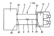
- FIG. 1 is a block diagram of the most basic embodiment of the audio adjustment circuit of the present invention.
- the audio adjustment circuit 1 of the embodiment of the present invention is a stereo audio output circuit including at least a right audio signal circuit (hereinafter, also referred to as an R side circuit) and a left audio signal circuit (hereinafter, also referred to as an L side circuit) on the R side.
- a resistor 5 is provided on the ground wire 4 common to each of the circuit and the L side circuit.
- the stereo circuit of the voice reproduction device 71 when the reproduced voice contains human vocal information, a specific resistance value is specified for each ground line 4 of the R side circuit and the L side circuit of the stereo circuit. This was done by finding that the human voice signal is attenuated by providing only the resistor 5 in the range. The cause of the attenuation is not clear at this time, but it is presumed that the signals in the frequency band related to human voice in the left and right stereo channels are mixed and canceled and attenuated.
- an experiment in which the effect of the voice adjustment circuit 1 of the present invention is specifically verified will be described in detail.
- a tablet terminal (iPad manufactured by Apple Inc.) is used as the audio playback device 71, and a plug device 10 provided with the audio adjustment circuit 1 shown in FIG. 1 is connected to the 3.5 mm headphone jack of the tablet terminal. Further, a headphone (Inner ear type ATH-C505 manufactured by Audio Technica) was connected as an audio output device 7 to the output side of the plug device 10. Then, while replacing the fixed resistor 5 (carbon resistance) of the voice adjustment circuit 1 with one having a different resistance value, a musical piece including a vocal was reproduced as a sound source and the decay state of the vocal was observed.
- a headphone Inner ear type ATH-C505 manufactured by Audio Technica
- vocals began to attenuate from a resistance of about 15 ⁇ , attenuated by about 50% with a resistance of about 50 ⁇ , and attenuated by about 80 to 90% with a resistance of about 100 to 300 ⁇ . Furthermore, with a resistance of about 400 to 500 ⁇ , the amount of vocal attenuation hardly changed. At this time as well, the sound of a specific musical instrument remained at almost normal volume, and the backing chorus remained without being attenuated depending on the music. Furthermore, when a sound source containing only human voice was reproduced and verified, it became almost inaudible at about 2.5 to 10 k ⁇ .
- variable resistor 50 of 0 to 1 k ⁇ (Supertech Electrical Co., Ltd.) was replaced with the variable resistor 50 of 0 to 500 ⁇ . , Ltd., small volume 1k ⁇ B) was connected, and the attenuation of 0 to 1k ⁇ was confirmed.
- the variable resistor 50 of 0 to 1 k ⁇ (Supertech Electrical Co., Ltd.) was replaced with the variable resistor 50 of 0 to 500 ⁇ . , Ltd., small volume 1k ⁇ B) was connected, and the attenuation of 0 to 1k ⁇ was confirmed.
- the resistance value of the resistor 5 provided on the ground wire 4 of the audio adjustment circuit 1 connected to the normal headphones is preferably 100 ⁇ or more, more preferably 300 ⁇ or more, and further preferably 400 ⁇ or more. It was confirmed that it was preferable. Further, it was confirmed that the upper limit value is preferably 10 k ⁇ , and the maximum value is more preferable.
- variable resistor 50 when the variable resistor 50 is used, 0 to 500 ⁇ is preferable, 0 to 1 k ⁇ is more preferable, and 0 to 10 k ⁇ is further preferable. Further, when the same verification was performed on headphones and small speakers of types other than the headphones used in the above verification experiments 1 and 2, it was confirmed that the same effects as those in the verification experiments 1 and 2 were obtained.
- the resistance value of the resistor 5 is 100 ⁇ to 1k ⁇ . Almost no vocal attenuation was observed in the range of. It is considered that this is because the attenuated audio signal is amplified by the amplifier in the subsequent stage, resulting in a normal audio output. Therefore, on the premise of audio output to a speaker having an amplifier 72 built as the audio output device 7, a verification experiment was further conducted by the following method.
- a plug device 10 provided with a voice adjustment circuit 1 is connected to a 3.5 mm headphone jack of a tablet terminal (iPad manufactured by Apple Inc.) as a sound playback device 71, and this plug is used.
- a speaker (SRS-Z050V manufactured by SONY) with a built-in amplifier 72 is connected to the device 10 as an audio output device 7, and while replacing the fixed resistor 5 with a different resistance value, a music including vocals is played as a sound source. The state of decay of vocals was observed.
- vocals began to attenuate from a resistance of about 3 k ⁇ , attenuated by about 50% with a resistance of about 7 to 10 k ⁇ , and attenuated by about 80 to 90% with a resistance of about 30 to 50 k ⁇ . Furthermore, the amount of attenuation did not change with a resistance of about 60 to 100 k ⁇ . In addition, when a sound source containing only human voice was reproduced and verified, it became almost completely inaudible at about 250 k ⁇ to 1 M ⁇ .
- variable resistor 50 of 0 to 100 k ⁇ (Supertech Electrical Co.) was replaced with the variable resistor 50 of 0 to 50 k ⁇ . , Ltd., small volume 100k ⁇ B) was connected, and the attenuation amount of 0 to 100k ⁇ was confirmed. As a result, further attenuation was confirmed for the music.
- the resistance value of the resistor 5 provided on the ground wire 4 of the audio adjustment circuit 1 connected to the speaker 7 with a built-in amplifier or the amplifier 72 to which the speaker is connected is preferably 30 k ⁇ or more, preferably 60 k ⁇ or more.
- the upper limit value is preferably 1 M ⁇ , and the maximum value is more preferable.
- the variable resistor 50 is provided, 0 to 50 k ⁇ is preferable, 0 to 100 k ⁇ is more preferable, and 0 to 1 M ⁇ is further preferable.
- the voice adjustment circuit 1 of the present invention is connected to a subsequent stage of a headphone amplifier circuit or the like provided in the voice reproduction device 71 (verification experiments 1 and 2), and a normal amplifier. It was confirmed that the resistance value range in which the vocal attenuation effect of the voice adjustment circuit 1 of the present invention is exhibited is different from that in the case of connecting to the previous stage of 72 (verification experiments 3 and 4).
- circuits having various configurations can be used in order to obtain the effect of the present invention more easily and surely. ..
- a circuit in which a fixed resistor 5 is combined, a circuit in which a fixed resistor 5 having a plurality of resistance values and a rotary switch 8 as shown in FIG. 7 are combined, and the like can be exemplified. As a result, it is possible to easily switch between the normal music reproduction state and the vocal attenuated state with the switch 8.
- the vocal can be gradually attenuated from the playback state of a normal musical piece having a resistance value of 0 ⁇ , and the user's favorite attenuation can be achieved. It is possible to hold it in a state.
- the voice adjustment circuit 1 of the present invention it is possible to surely obtain a predetermined voice attenuation effect with a very simple configuration and low cost. From the above demonstration experiment, it was confirmed that the audio output device 7 to be connected is attenuated by the audio adjustment circuit 1 of the present invention at least in any one of the headphones, the speaker, the amplifier, and the speaker with a built-in amplifier. 1 may be incorporated in various audio output devices 7 in advance. Thereby, for example, the effect of the voice adjustment circuit 1 of the present invention can be imparted to a mobile terminal device, a personal computer, various music playback devices, and the like.
- the plug device 10 can be formed so that the voice adjustment circuit 1 can be more easily connected to an existing device.
- the right audio signal terminal 20 hereinafter, also referred to as R terminal
- the left audio signal terminal 30 hereinafter, also referred to as L terminal.
- a phone plug 60 having a ground terminal 40 and a phone jack 61 having at least an R terminal 20, an L terminal 30, and a ground terminal 40 are provided, and a circuit for connecting each terminal of the phone plug 60 and the phone jack 61 is provided. It can be a plug device 10.
- variable resistor 51 with a switch is used in the plug device 10 shown in FIGS. 8 to 10
- the configuration of the resistor 5 provided in the ground wire 4 in the plug device 10 of the present invention is the above-mentioned demonstration experiment 1. It is also possible to apply the circuit configuration of the embodiment shown in FIGS. 1 to 7 verified in ⁇ 4. That is, it can be a plug device 10 provided with a resistor 5 corresponding to the audio output device 7 to be connected.
- the vocal attenuation effect can be easily obtained by connecting between the headphone jack of the existing sound reproduction device 71 and the sound output device 7.
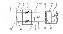
- a short-range wireless communication circuit can be provided on the voice input side, or a short-range wireless communication device 9 can be connected as shown in FIG.
- Specific communication methods of the short-range wireless communication device 9 include, for example, wireless LAN such as WiFi (registered trademark), Bluetooth (registered trademark), BLE (Bluetooth Low Energy (registered trademark)), Zigbee (registered trademark) and the like.
- WPAN Wi-Filess Personal Area Network
- NFC Near Field Communication
- other near-field wireless communications can be exemplified.
- the voice signal wirelessly transmitted from the voice reproduction device 71 can be brought close to each other. It is possible to receive the signal by the range wireless communication circuit or the short range wireless communication device 9, attenuate the vocal, and output it from the voice output device 7.
- the plug device of the present invention may be provided with a volume adjusting circuit 91 in which the overall volume can be adjusted as shown in FIG.
- the overall volume tends to be reduced by the volume of the vocal.
- the volume of the volume adjusting circuit 91 it is possible to adjust the volume to an appropriate level in a state where the vocal is attenuated at hand.
- a tablet terminal is used as the audio reproduction device 71, a plug device 10 provided with the audio adjustment circuit 1 is connected to the 3.5 mm headphone jack of the tablet terminal, and the headphones of the audio output device 7 are further connected.
- an amplifier 72 such as a headphone amplifier or an integrated amplifier is connected to an audio playback device 71 such as a record player, a cassette player, or a CD player, and the headphone jack of the amplifier 72 is connected.
- the plug device 10 of the present invention may be connected.
- a lead type carbon resistor is used as the fixed resistor 5, but a surface mount type chip resistor or the like can also be used.
- the variable resistor 51 with a rotary switch is used as the variable resistor 50, but a slide type variable resistor or a semi-fixed resistor can also be used.
- a microphone or an apparatus is used, although a plug device 10 having a three-pole phone plug 60 having an R terminal 20, an L terminal 30 and a ground terminal 40 and a phone jack 61 is used. It can also be a plug device 10 including a four-pole phone plug 60 having poles for control and a phone jack 61.
- each ground wire 4 is used as a common ground wire 4, and a resistor 5 is provided on the ground wire 4, but the ground wire 4 is not used as a common ground wire 4 according to the specifications of the audio reproduction device 71 that outputs an audio signal.
- a predetermined resistor 5 may be provided on each ground wire 4.
- the audio adjustment circuit 1 of the present invention it is possible to surely obtain a predetermined audio output attenuation effect with a very simple configuration and low cost.
- a simple karaoke device can be obtained by playing back a musical piece containing vocals through the voice adjustment circuit 1 of the present invention and outputting it from the voice output device 7.
- the variable resistor 50 as the resistor 5
- the amount of attenuation of the vocal can be made arbitrary, and the vocal can be attenuated in a desired state to listen to music.
- it can be suitably used for practicing a backing chorus part, copying a part of a specific musical instrument, or the like.
Landscapes
- Physics & Mathematics (AREA)
- Engineering & Computer Science (AREA)
- Acoustics & Sound (AREA)
- Signal Processing (AREA)
- Circuit For Audible Band Transducer (AREA)
Priority Applications (1)
| Application Number | Priority Date | Filing Date | Title |
|---|---|---|---|
| JP2022515457A JPWO2021210689A1 (https=) | 2020-04-15 | 2021-04-12 |
Applications Claiming Priority (2)
| Application Number | Priority Date | Filing Date | Title |
|---|---|---|---|
| JP2020087737 | 2020-04-15 | ||
| JP2020-087737 | 2020-04-15 |
Publications (1)
| Publication Number | Publication Date |
|---|---|
| WO2021210689A1 true WO2021210689A1 (ja) | 2021-10-21 |
Family
ID=78085135
Family Applications (1)
| Application Number | Title | Priority Date | Filing Date |
|---|---|---|---|
| PCT/JP2021/016232 Ceased WO2021210689A1 (ja) | 2020-04-15 | 2021-04-12 | 音声調整回路及びこれを用いたプラグ装置 |
Country Status (2)
| Country | Link |
|---|---|
| JP (1) | JPWO2021210689A1 (https=) |
| WO (1) | WO2021210689A1 (https=) |
Citations (3)
| Publication number | Priority date | Publication date | Assignee | Title |
|---|---|---|---|---|
| JPH01175093U (https=) * | 1988-05-30 | 1989-12-13 | ||
| JPH05344598A (ja) * | 1990-02-12 | 1993-12-24 | Georg Diamantidis | 多重チャネル電気−音響装置の出力信号調整回路構成 |
| JP2015139215A (ja) * | 2014-01-22 | 2015-07-30 | 光寶電子(廣州)有限公司 | ブルートゥース送受信機、リモコン付イヤホンモジュール及び携帯装置モジュール |
-
2021
- 2021-04-12 WO PCT/JP2021/016232 patent/WO2021210689A1/ja not_active Ceased
- 2021-04-12 JP JP2022515457A patent/JPWO2021210689A1/ja active Pending
Patent Citations (3)
| Publication number | Priority date | Publication date | Assignee | Title |
|---|---|---|---|---|
| JPH01175093U (https=) * | 1988-05-30 | 1989-12-13 | ||
| JPH05344598A (ja) * | 1990-02-12 | 1993-12-24 | Georg Diamantidis | 多重チャネル電気−音響装置の出力信号調整回路構成 |
| JP2015139215A (ja) * | 2014-01-22 | 2015-07-30 | 光寶電子(廣州)有限公司 | ブルートゥース送受信機、リモコン付イヤホンモジュール及び携帯装置モジュール |
Non-Patent Citations (1)
| Title |
|---|
| "How to listen to vocal cancel sound with earphones and remodeling of mini plug", SUN CHAN BLOG, 15 May 2015 (2015-05-15), Retrieved from the Internet <URL:http://sirasaka.seesaa.net/article/post-0815.html> [retrieved on 20210624] * |
Also Published As
| Publication number | Publication date |
|---|---|
| JPWO2021210689A1 (https=) | 2021-10-21 |
Similar Documents
| Publication | Publication Date | Title |
|---|---|---|
| CN101401399B (zh) | 提供环境声音的耳机 | |
| KR20080038586A (ko) | 청력손실을 방지하기 위한 오디오 볼륨 조절 방법 및 장치 | |
| US20100027799A1 (en) | Asymmetrical delay audio crosstalk cancellation systems, methods and electronic devices including the same | |
| US8577052B2 (en) | Headphone accessory | |
| EP2410762B1 (en) | Headphone | |
| US8718295B2 (en) | Headset assembly with recording function for communication | |
| US8666098B2 (en) | Single earphone for stereo and monaural audio devices | |
| GB2082019A (en) | Headphones | |
| US20070098202A1 (en) | Variable output earphone system | |
| CN116367050A (zh) | 处理音频信号的方法、存储介质、电子设备和音频设备 | |
| US7623669B2 (en) | Simplified amplifier providing sharing of music with enhanced spatial presence through multiple headphone jacks | |
| CN101129088A (zh) | 具有增强的立体声图像的便携式设备 | |
| WO2021210689A1 (ja) | 音声調整回路及びこれを用いたプラグ装置 | |
| CN111756929A (zh) | 多屏终端音频播放方法、装置、终端设备以及存储介质 | |
| JP2008537374A (ja) | 音声データ処理装置、音声データ処理方法、プログラム要素及びコンピューター可読媒体 | |
| JP2004201195A (ja) | ヘッドホン装置 | |
| JP5397731B2 (ja) | 音漏れシミュレータ | |
| JP6614194B2 (ja) | 音響処理システムおよび信号処理装置 | |
| Sigismondi | Personal monitor systems | |
| CN221227711U (zh) | 一种可消除高频齿音的有源音箱电路 | |
| CN2575927Y (zh) | 一种耳机线控器 | |
| JP2007006432A (ja) | バイノーラル再生装置 | |
| KR20050060924A (ko) | 이동 통신 단말기의 외부 스피커 장치 | |
| CA1132460A (en) | Monitor ampliphones | |
| CN119653283A (zh) | 音频信号传输装置、音频设备和音频信号的播放方法 |
Legal Events
| Date | Code | Title | Description |
|---|---|---|---|
| 121 | Ep: the epo has been informed by wipo that ep was designated in this application |
Ref document number: 21789518 Country of ref document: EP Kind code of ref document: A1 |
|
| DPE1 | Request for preliminary examination filed after expiration of 19th month from priority date (pct application filed from 20040101) | ||
| ENP | Entry into the national phase |
Ref document number: 2022515457 Country of ref document: JP Kind code of ref document: A |
|
| NENP | Non-entry into the national phase |
Ref country code: DE |
|
| 122 | Ep: pct application non-entry in european phase |
Ref document number: 21789518 Country of ref document: EP Kind code of ref document: A1 |