WO2021210605A1 - エキサイタ - Google Patents
エキサイタ Download PDFInfo
- Publication number
- WO2021210605A1 WO2021210605A1 PCT/JP2021/015437 JP2021015437W WO2021210605A1 WO 2021210605 A1 WO2021210605 A1 WO 2021210605A1 JP 2021015437 W JP2021015437 W JP 2021015437W WO 2021210605 A1 WO2021210605 A1 WO 2021210605A1
- Authority
- WO
- WIPO (PCT)
- Prior art keywords
- magnetic circuit
- voice coil
- guide member
- fixed
- exciter
- Prior art date
- Legal status (The legal status is an assumption and is not a legal conclusion. Google has not performed a legal analysis and makes no representation as to the accuracy of the status listed.)
- Ceased
Links
Images



Classifications
-
- B—PERFORMING OPERATIONS; TRANSPORTING
- B60—VEHICLES IN GENERAL
- B60R—VEHICLES, VEHICLE FITTINGS, OR VEHICLE PARTS, NOT OTHERWISE PROVIDED FOR
- B60R11/00—Arrangements for holding or mounting articles, not otherwise provided for
- B60R11/02—Arrangements for holding or mounting articles, not otherwise provided for for radio sets, television sets, telephones, or the like; Arrangement of controls thereof
-
- H—ELECTRICITY
- H04—ELECTRIC COMMUNICATION TECHNIQUE
- H04R—LOUDSPEAKERS, MICROPHONES, GRAMOPHONE PICK-UPS OR LIKE ACOUSTIC ELECTROMECHANICAL TRANSDUCERS; ELECTRIC HEARING AIDS; PUBLIC ADDRESS SYSTEMS
- H04R1/00—Details of transducers, loudspeakers or microphones
-
- H—ELECTRICITY
- H04—ELECTRIC COMMUNICATION TECHNIQUE
- H04R—LOUDSPEAKERS, MICROPHONES, GRAMOPHONE PICK-UPS OR LIKE ACOUSTIC ELECTROMECHANICAL TRANSDUCERS; ELECTRIC HEARING AIDS; PUBLIC ADDRESS SYSTEMS
- H04R7/00—Diaphragms for electromechanical transducers; Cones
- H04R7/02—Diaphragms for electromechanical transducers; Cones characterised by the construction
- H04R7/04—Plane diaphragms
-
- H—ELECTRICITY
- H04—ELECTRIC COMMUNICATION TECHNIQUE
- H04R—LOUDSPEAKERS, MICROPHONES, GRAMOPHONE PICK-UPS OR LIKE ACOUSTIC ELECTROMECHANICAL TRANSDUCERS; ELECTRIC HEARING AIDS; PUBLIC ADDRESS SYSTEMS
- H04R9/00—Transducers of moving-coil, moving-strip, or moving-wire type
- H04R9/02—Details
-
- H—ELECTRICITY
- H04—ELECTRIC COMMUNICATION TECHNIQUE
- H04R—LOUDSPEAKERS, MICROPHONES, GRAMOPHONE PICK-UPS OR LIKE ACOUSTIC ELECTROMECHANICAL TRANSDUCERS; ELECTRIC HEARING AIDS; PUBLIC ADDRESS SYSTEMS
- H04R9/00—Transducers of moving-coil, moving-strip, or moving-wire type
- H04R9/02—Details
- H04R9/04—Construction, mounting, or centering of coil
Definitions
- the present invention relates to an exciter, and more particularly to an exciter used by being fixed to the interior and exterior of a vehicle.
- a speaker device that vibrates a cone-shaped diaphragm to reproduce sound has been widely used in a vehicle, for example, in the passenger compartment of an automobile, in order to reproduce the sound of music or sound.
- This speaker device is embedded and arranged in the doors for the left and right front seats, for example.
- An object of the present invention is to provide an exciter capable of creating a high-quality sound space with a sense of presence and easy installation work because the voice coil can be securely and easily fixed to the vibrating member. It is in.
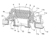
- the exciter of the present invention has the following configuration. (1) A magnetic circuit fixed to a support member. (2) A voice coil that is movably arranged with respect to the magnetic circuit and fixed to a vibrating member. (3) A guide member fixed to the voice coil and provided with a contact portion with the vibrating member. (4) A pressed portion provided on the guide member, which is arranged at a predetermined interval with respect to the magnetic circuit. (5) The pressed portion is provided at a position where the voice coil is fixed to the vibrating member and comes into contact with the magnetic circuit or the supporting member when the magnetic circuit is pressed toward the vibrating member.
- the magnetic circuit is fixed to the vibrating member via a cushion material.
- the guide member includes a tubular portion fitted to the inner or outer circumference of the voice coil, and a flange portion provided on the vibrating member side of the tubular portion, and the contact portion is the contact portion. It is provided on the flange portion.
- a rib portion is provided between the cylindrical portion and the flange portion.
- the magnetic circuit includes a pot yoke whose voice coil side is open, a magnet and a pole piece are arranged in the pot yoke, the voice coil is inserted into the magnetic gap of the magnetic circuit, and the guide member.
- the pressed portion provided at the upper end of the is arranged so as to face the pole piece, and the pressed portion and the pole piece come into contact with each other when the magnetic circuit and the voice coil are close to each other.
- the upper end of the guide member is lower than the mounting position of the coil body of the voice coil.
- the support member is provided with a stopper that restricts the movement of the magnetic circuit toward the vibrating member.
- the guide member is provided with an adhesive member for adhering the vibrating member and the guide member.
- a fixing member for mechanically connecting the vibrating member and the guide member is provided.
- the voice coil can be securely and easily fixed to the vibrating member, it is possible to provide an exciter that can easily fix the voice coil and reproduce high-quality sound.
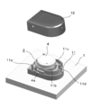
- the exciter of this embodiment is used by being fixed to the vibrating member 1.
- the vibrating member 1 is an interior / exterior material for a vehicle such as a pillar, a door, a dashboard, an instrument panel, a console box, and a ceiling. Since the exciter of the present embodiment is used by being attached to a vehicle or the like in various directions, the vertical positional relationship is changed and used, but for convenience of explanation, the vibrating member 1 side. Will be described below, with the exciter side facing up.
- the exciter of this embodiment has a magnetic circuit 2 and a voice coil 3.
- one set of magnetic circuit 2 and voice coil 3 is provided for the vibrating member 1, but a plurality of sets of magnetic circuit 2 and voice coil 3 may be provided for one vibrating member. ..
- the magnetic circuit 2 of the present embodiment uses an internal magnetic circuit, but an external magnetic circuit may also be used.
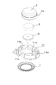
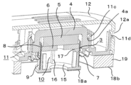
- the magnetic circuit 2 includes a pot yoke 4, a magnet 5, and a pole piece 6.
- the voice coil 3 is formed by winding a coil body 8 around a coil bobbin 9 and fixing the voice coil 3 to a guide member 10.
- the pot yoke 4 has a cup shape with the voice coil 3 side open, and the magnet 5 and the pole piece 6 are arranged vertically in the pot yoke 4.
- the pole piece 6 is also called a plate and is circular and has a hole in the center.
- the exciter includes a damper 7 and a support member 11.
- the damper 7 is a ring-shaped member having a wavy cross section, and its outer peripheral portion is fixed to the support member 11. The inner circumference of the damper 7 is fixed to the outer circumference of the voice coil 3.
- the support member 11 is a holder that holds the magnetic circuit 2.
- the support member 11 is a frame-shaped member provided with a hole 11a penetrating in a circle at the lower part.
- the support member 11 has a positioning portion 11b for accurately positioning the magnetic circuit 2.
- the positioning portion 11b is a rib-shaped member and is provided around the circular hole 11a of the support member 11.
- the pot yoke 4 is fitted inside the positioning portion 11b with the lower end surface of the cup-shaped pot yoke 4 in contact with the edge portion of the hole 11a.
- a cover 12 having an open lower portion is fixed to the upper outer periphery of the magnetic circuit 2 so as to cover the magnetic circuit 2.
- the support member 11 is provided with a locking projection 11d that engages with the cover 12 in order to fix the cover 12.
- the upper end of the locking projection 11d projects outward in a key shape.
- the locking projection 11d can be deformed in a direction orthogonal to the cover 12 due to the elasticity of the resin support member 11.
- the number of the locking projections 11d is not limited to this shape, and the number can be increased or decreased as needed.
- the support member 11 can also fix the cover 12 by adhesion or screwing without providing the locking projection 11d.
- the cover 12 is provided with a locking hole 12a for fixing to the support member 11.
- the locking hole 12a engages with the engaging projection 11d installed on the support member 11.
- the same number of locking holes 12a as the engaging protrusions 11d are provided.
- the voice coil 3 is fixed to the guide member 10.
- the number of voice coils 3 is one, but two or more may be used.
- Leading wires 13 are drawn from both ends of the voice coil 3. Although not shown, the leader line 13 is connected to an external audio device.
- a guide member 10 is provided between the vibrating member 1 and the voice coil 3.
- the guide member 10 has a cylindrical portion 14, a flange portion 15, and a rib portion 16.
- the tubular portion 14 is a cylindrical member and is fitted to the inner circumference of the voice coil 3 in the present embodiment, but may be fitted to the outer circumference of the voice coil 3.
- the voice coil 3 is integrated with the guide member 10 by fixing the inner peripheral surface of the voice coil 3 and the outer peripheral surface of the tubular portion 14 with an adhesive.
- the guide member 10 includes a contact portion with the vibrating member 1.
- the guide member 10 has a flange portion 15 having a larger area than the pressed portion 17 on the contact portion side with the vibrating member 1.
- the lower surface of the flange portion 15 serves as a contact portion with the vibrating member 1.
- the "contact portion” in the present specification includes not only a portion in which the guide member 10 and the vibrating member 1 are in direct contact with each other, but also a portion in which the guide member 10 and the vibrating member 1 are indirect contact with each other via a double-sided adhesive tape or the like.
- an adhesive member 18a for adhering the guide member 10 and the vibrating member 1 is provided on the lower surface of the flange portion 15 which is the contact portion of the guide member 10.
- the adhesive member 18a is for adhering the guide member 10 and the vibrating member 1.
- an appropriate member such as an adhesive containing a pressure-sensitive adhesive can be used, but in order to securely and easily fix the guide member 10 to the vibrating member 1, a double-sided adhesive tape is preferable. ..
- the double-sided adhesive tape is preferably made of a material as thin as possible, not a material having cushioning properties.
- the adhesive member 18a uses a ring-shaped double-sided adhesive tape that follows the shape of the lower surface of the flange portion 15 in order to securely and easily fix the guide member 10 to the vibrating member 1.
- a rib portion 16 is provided between the inner peripheral surface of the tubular portion 14 and the upper surface of the flange portion 15. In the present embodiment, four rib portions 16 are provided at equal intervals, but the number of rib portions 16 can be varied.
- the upper end of the tubular portion 14 has a pressed portion 17 that comes into contact with the pole piece 6 when the magnetic circuit 2 and the voice coil 3 are in close proximity to each other.
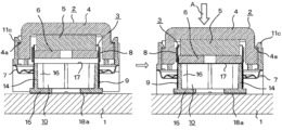
- the pressed portion 17 is when the magnetic circuit 2 and the voice coil 3 are separated from each other, that is, when the exciter is not pressed toward the vibrating member 1 before and after the work of fixing the exciter to the vibrating member 1. It is arranged so as to maintain a predetermined interval with respect to the magnetic circuit 2. Further, as shown in the right figure of FIG.
- the pressed portion 17 hits the magnetic circuit 2 when the magnetic circuit 2 and the voice coil 3 are close to each other, that is, when the exciter is fixed and pressed toward the vibrating member 1. Touch.
- the height of the pressed portion 17 is preferably lower than that of the lower end of the coil body 8 of the voice coil 3. If the guide member 10 is tall and the position of the pressed portion 17 is high, the pressed portion 17 and the coil body 8 of the voice coil 3 are close to each other. In this case, the magnetic gap of the magnetic circuit 2 into which the voice coil 3 is inserted becomes large, and the driving force is reduced by that amount.
- the back of the guide member 10 is made lower than the lower end of the coil body 8 of the voice coil 3, and the upper end of the guide member 10 and the coil body 8 of the voice coil 3 are in the radial direction. It is configured so that it does not overlap in.
- a cushion material 19 is provided between the vibrating member 1 and the support member 11.
- the cushion material 19 is made of an elastic material such as sponge or rubber.
- An adhesive member 18b such as double-sided adhesive tape is attached to the lower portion of the cushion material 19.
- the cushion material 19 moves the voice coil 3. It has a thickness and elasticity that can absorb.
- the exciter of this embodiment is used by being fixed to a vibrating member 1 which is an interior / exterior material of an automobile.
- a vibrating member 1 which is an interior / exterior material of an automobile.
- one side of the double-sided adhesive tape which is the adhesive member 18a, is attached to the contact portion of the guide member 10 in advance at the time of assembling the exciter.
- the protective sheet on the other side of the double-sided adhesive tape attached to the contact portion is peeled off.
- the protective sheet of the adhesive member 18b attached to the lower surface of the cushion material 19 provided on the support member 11 is also peeled off.
- the magnetic circuit 2 or the support member 11 is pressed from above toward the vibrating member 1 by manual operation or an automatic machine.
- the magnetic circuit 2 pressed directly or indirectly via the support member 11 moves downward, and the pole piece 6 moves to the pressed portion 17 of the guide member 10.
- a force is further applied to the magnetic circuit 2, so that the guide member 10 is strongly pressed against the vibrating member 1 via the adhesive member 18a. In this way, the guide member 10 and the vibrating member 1 are firmly fixed by sufficiently applying the force required for adhering the adhesive member 18a.
- the cushion material 19 has a thickness such that there is a gap between the magnetic circuit 2 and the guide member 10 before and after fixing in the no-load state. Therefore, before the exciter is fixed to the vibrating member 1, there is a gap between the pole piece 6 and the guide member 10 due to the thickness of the cushion material 19, and the pole piece 6 and the guide member 10 are arranged apart from each other. NS.
- the exciter is being fixed, when the magnetic circuit 2 is pressed toward the vibrating member 1, a force is applied to the cushion material 19 via the support member 11, and the cushion material 19 is compressed.
- the adhesive member 18b is also provided below the cushion material 19. Therefore, when the magnetic circuit 2 or the support member 11 is pressed toward the vibrating member 1 from above to below while the adhesive member 18b has an adhesive force, the cushion material 19 is compressed. Since the cushion material 19 is strongly pressed against the vibrating member 1 via the adhesive member 18b, the cushion material 19 and the vibrating member 1 are firmly fixed by the adhesive member 18b.
- the magnetic circuit 2 moves upward due to the elasticity of the cushion material 19. Since the thickness of the cushion material 19 returns to the original thickness, the pole piece 6 of the magnetic circuit 2 moves to a state where a predetermined gap (gap) exists between the cushion material 19 and the guide member 10.
- the voice coil 3 is electrically connected to an external device by leader wires 13 drawn from both ends thereof.
- leader wires 13 drawn from both ends thereof.
- the voice coil 3 vibrates due to the interaction between the magnetic circuit 2 and the voice coil 3.
- the voice coil 3 vibrates, a predetermined distance is secured between the pole piece 6 of the magnetic circuit 2 and the guide member 10, so that the vibration of the voice coil 3 is not hindered and good quality sound is generated. Since the voice coil 3 is firmly fixed to the vibrating member 1 via the guide member 10, when the voice coil 3 vibrates, the vibrating member 1 vibrates smoothly and a good sound is generated.
- the voice coil 3 can be securely fixed to the vibrating member 1 only by peeling off the protective sheet of the double-sided adhesive tape of the adhesive member 18a and pressing it. Therefore, it is possible to save the labor and time for forming the joint member as in the prior art, and the work of attaching the exciter is easy. In addition, it is possible to reduce the cost of installing the exciter.
- the guide member 10 has a function as a stopper and can prevent the voice coil 3 from bottoming. In this way, the prevention of bottoming improves the reliability of the exciter when it is fixed, and makes it possible to withstand long-term use as an exciter.
- the guide member 10 When the exciter is fixed, the guide member 10 receives the force required for adhesion and can directly transmit the force to the vibrating member 1. Therefore, it is possible to prevent an overload on the damper during fixing.
- the height of the guide member 10 is lower than the lower end (mounting position) of the coil body 8 of the voice coil 3, the magnetic gap of the magnetic circuit 2 into which the voice coil 3 is inserted can be reduced. Therefore, the driving force is improved, and it is possible to provide an exciter capable of reproducing high-quality sound.
- MC type moving coil type
- MM type moving magnet
- the moving coil type (MC type) is adopted.
- the lightweight voice coil 3 can be vibrated, and the vibrating member 1 can be vibrated according to the input signal as compared with the MM type.
- a stopper 11e which is slightly shorter than the wall thickness of the cushion member 19, is projected from the lower surface of the support member 11 toward the vibrating member 1.
- Other configurations are the same as those in the first embodiment.
- the distance between the lower end of the stopper 11e and the surface of the vibrating member 1 is substantially equal to the distance between the magnetic circuit 2 and the pressed portion 17.
- the cushion material 19 does not necessarily have to be provided, and the adhesive member 18b may be provided directly at the lower end of the support member 11, and the adhesive member 18b itself may have cushioning properties.
- the cushion material is not limited to a member such as a sponge or rubber, and a leaf spring provided separately from the support member may be used, or a member that elastically deforms may be provided as a part of the support member. Further, in the illustrated embodiment, the cushion material 19 is fixed to the magnetic circuit 2 via the support member 11, but may be directly fixed to a part of the magnetic circuit 2.
- the tubular portion 14 does not have to have a cylindrical shape having a wall surface on the entire circumference, and a plurality of arc-shaped members may be arranged at predetermined intervals.
- the flange portion 15 does not necessarily have to be provided on the entire periphery of the lower portion of the tubular portion 14.
- the shapes of the tubular portion 14 and the flange portion 15 do not matter as long as the pressed portion 17 is separated from or in contact with the magnetic circuit 2 and the pressing force from the magnetic circuit 2 is transmitted when the adhesive member 18a is joined. ..
- the pressed portion 17 may come into contact with any part of the magnetic circuit 2. As long as a force is applied to the guide member 10 when the magnetic circuit 2 is pressed, the magnetic circuit 2 may come into contact with the pot yoke 4 or the support member 11.
- both are integrally formed by press fitting, adhesion, or insert molding. It is also possible to do.
- the adhesive member 18a for fixing the guide member 10 to the vibrating member 1 an adhesive other than the double-sided adhesive tape can be used. In that case, by pressing the magnetic circuit 2, the guide member 10 can be pressurized for a certain period of time, and the adhesiveness of the adhesive can be improved.
- FIGS. 8A and 8B are cross-sectional views showing an embodiment in which a fixing member for mechanically connecting the vibrating member 1 and the guide member 10 is provided instead of the adhesive member 18a.
- the vibrating member 1 is provided with a locking claw 20 having a key-shaped tip, and the locking claw 20 is engaged with the outer peripheral portion of the flange portion 15.
- the fixing member is not limited to the locking claw 20 as shown in the figure as long as the guide member 10 is fixed to the vibrating member 1.
- the protective sheet of the adhesive member 18b attached to the lower surface of the cushion material 19 provided on the support member 11 is peeled off.
- the adhesive member 18b having an adhesive force
- the magnetic circuit 2 or the support member 11 is pressed from above toward the vibrating member 1 by manual operation or an automatic machine.
- the magnetic circuit 2 pressed directly or indirectly via the support member 11 moves downward, and the pole piece 6 moves to the pressed portion 17 of the guide member 10.
- a force is further applied to the magnetic circuit 2, so that the guide member 10 is strongly pressed against the vibrating member 1.
- the outer peripheral portion of the flange portion 15 hits the inclined surface of the key-shaped tip of the locking claw 20 and descends while pushing the locking claw 20 outward, and finally the locking claw 20 and the flange portion 15 Engage with the outer circumference.
- the locking claw 20 provided on the vibrating member 1 engages with the outer peripheral portion of the flange portion 15 of the guide member 10, so that the guide member 10 and the vibrating member 1 are firmly fixed.
- the magnetic circuit 2 moves upward due to the elasticity of the cushion material 19.
- the thickness of the cushion material 19 returns to the original thickness as shown in FIG. 8B, so that the pole piece 6 of the magnetic circuit 2 moves to a state where a predetermined distance (gap) exists between the cushion material 19 and the guide member 10. do.
- the fixing member since the fixing member has a mechanical engagement structure such as a locking claw 20, the voice coil 3 can be easily attached to the vibrating member 1 without using a tool or an adhesive. It becomes possible to fix it securely.
- the support member 11 may be fixed to the vibrating member 1 by a mechanical engagement structure such as a locking claw without using the adhesive member 18b.
- an embodiment in which a fixing member for mechanically connecting the vibrating member 1 and the guide member 10 is provided is provided.
- An adhesive member 18a may be provided at the contact portion, and a fixing member that mechanically connects the vibrating member 1 and the guide member 10 may be used.
Landscapes
- Engineering & Computer Science (AREA)
- Physics & Mathematics (AREA)
- Acoustics & Sound (AREA)
- Signal Processing (AREA)
- Mechanical Engineering (AREA)
- Multimedia (AREA)
- Audible-Bandwidth Dynamoelectric Transducers Other Than Pickups (AREA)
Priority Applications (1)
| Application Number | Priority Date | Filing Date | Title |
|---|---|---|---|
| JP2022515412A JP7688624B2 (ja) | 2020-04-17 | 2021-04-14 | エキサイタ |
Applications Claiming Priority (2)
| Application Number | Priority Date | Filing Date | Title |
|---|---|---|---|
| JP2020073860 | 2020-04-17 | ||
| JP2020-073860 | 2020-04-17 |
Publications (1)
| Publication Number | Publication Date |
|---|---|
| WO2021210605A1 true WO2021210605A1 (ja) | 2021-10-21 |
Family
ID=78084580
Family Applications (1)
| Application Number | Title | Priority Date | Filing Date |
|---|---|---|---|
| PCT/JP2021/015437 Ceased WO2021210605A1 (ja) | 2020-04-17 | 2021-04-14 | エキサイタ |
Country Status (2)
| Country | Link |
|---|---|
| JP (1) | JP7688624B2 (https=) |
| WO (1) | WO2021210605A1 (https=) |
Cited By (2)
| Publication number | Priority date | Publication date | Assignee | Title |
|---|---|---|---|---|
| DE102023002642A1 (de) | 2023-06-29 | 2025-01-02 | Mercedes-Benz Group AG | Funktionsintegration Soundgenerator in Unterbodenverkleidung |
| JP2025102423A (ja) * | 2023-12-26 | 2025-07-08 | ソニー・ホンダモビリティ株式会社 | 車両の室内構造 |
Citations (3)
| Publication number | Priority date | Publication date | Assignee | Title |
|---|---|---|---|---|
| JPS5848187U (ja) * | 1981-09-25 | 1983-03-31 | 日産自動車株式会社 | 車両用音響装置 |
| JP2002016993A (ja) * | 2000-06-28 | 2002-01-18 | Cyas:Kk | 展示場における案内方法 |
| JP2004241801A (ja) * | 2003-02-03 | 2004-08-26 | Authentic Ltd | パネル型スピーカ |
-
2021
- 2021-04-14 WO PCT/JP2021/015437 patent/WO2021210605A1/ja not_active Ceased
- 2021-04-14 JP JP2022515412A patent/JP7688624B2/ja active Active
Patent Citations (3)
| Publication number | Priority date | Publication date | Assignee | Title |
|---|---|---|---|---|
| JPS5848187U (ja) * | 1981-09-25 | 1983-03-31 | 日産自動車株式会社 | 車両用音響装置 |
| JP2002016993A (ja) * | 2000-06-28 | 2002-01-18 | Cyas:Kk | 展示場における案内方法 |
| JP2004241801A (ja) * | 2003-02-03 | 2004-08-26 | Authentic Ltd | パネル型スピーカ |
Cited By (3)
| Publication number | Priority date | Publication date | Assignee | Title |
|---|---|---|---|---|
| DE102023002642A1 (de) | 2023-06-29 | 2025-01-02 | Mercedes-Benz Group AG | Funktionsintegration Soundgenerator in Unterbodenverkleidung |
| JP2025102423A (ja) * | 2023-12-26 | 2025-07-08 | ソニー・ホンダモビリティ株式会社 | 車両の室内構造 |
| JP7839139B2 (ja) | 2023-12-26 | 2026-04-01 | ソニー・ホンダモビリティ株式会社 | 車両の室内構造 |
Also Published As
| Publication number | Publication date |
|---|---|
| JP7688624B2 (ja) | 2025-06-04 |
| JPWO2021210605A1 (https=) | 2021-10-21 |
Similar Documents
| Publication | Publication Date | Title |
|---|---|---|
| US7177438B2 (en) | Speaker for vehicle and mounting structure of the speaker | |
| US5734131A (en) | Speaker mount structure of vehicle | |
| JP7688624B2 (ja) | エキサイタ | |
| US7325648B2 (en) | Frame for speaker device and speaker device | |
| US20050129265A1 (en) | Exciter for directly vibrating board and speaker apparatus used the same | |
| JP2006180368A (ja) | 車両の内装板を振動板としたスピーカ装置 | |
| JP7756701B2 (ja) | エキサイタ及びスピーカ | |
| JP4578202B2 (ja) | 車両用の内装板を振動板としたスピーカ装置及び車両用の内装板 | |
| JP3882589B2 (ja) | スピーカ | |
| JP2010258955A (ja) | 加振型音響発生器 | |
| JPS6143351Y2 (https=) | ||
| JP7708676B2 (ja) | 車両用スピーカ | |
| JP4404721B2 (ja) | スピーカユニット | |
| JPS6143350Y2 (https=) | ||
| JPH018067Y2 (https=) | ||
| JP4203444B2 (ja) | 複合型スピーカ装置 | |
| JP2005064712A (ja) | パネル型スピーカ装置および振動板 | |
| JP4140164B2 (ja) | スピーカ | |
| JP2024135800A (ja) | スピーカー装置およびその設置構造 | |
| CN223744895U (zh) | 一种振动抑制扬声器 | |
| CN223744896U (zh) | 一种振动抑制扬声器的振动缓冲件 | |
| CN212344291U (zh) | 一种背板组件及显示器 | |
| JP7286576B2 (ja) | スピーカ | |
| JP3991896B2 (ja) | スピーカ装置 | |
| JP3942067B2 (ja) | 自動車用ドアライニング |
Legal Events
| Date | Code | Title | Description |
|---|---|---|---|
| 121 | Ep: the epo has been informed by wipo that ep was designated in this application |
Ref document number: 21789237 Country of ref document: EP Kind code of ref document: A1 |
|
| ENP | Entry into the national phase |
Ref document number: 2022515412 Country of ref document: JP Kind code of ref document: A |
|
| NENP | Non-entry into the national phase |
Ref country code: DE |
|
| 122 | Ep: pct application non-entry in european phase |
Ref document number: 21789237 Country of ref document: EP Kind code of ref document: A1 |