WO2021210244A1 - 鉛蓄電池用集電体、鉛蓄電池用正極板、および鉛蓄電池 - Google Patents
鉛蓄電池用集電体、鉛蓄電池用正極板、および鉛蓄電池 Download PDFInfo
- Publication number
- WO2021210244A1 WO2021210244A1 PCT/JP2021/003250 JP2021003250W WO2021210244A1 WO 2021210244 A1 WO2021210244 A1 WO 2021210244A1 JP 2021003250 W JP2021003250 W JP 2021003250W WO 2021210244 A1 WO2021210244 A1 WO 2021210244A1
- Authority
- WO
- WIPO (PCT)
- Prior art keywords
- current collector
- lead
- bone
- positive electrode
- electrode plate
- Prior art date
- Legal status (The legal status is an assumption and is not a legal conclusion. Google has not performed a legal analysis and makes no representation as to the accuracy of the status listed.)
- Ceased
Links
Images





Classifications
-
- H—ELECTRICITY
- H01—ELECTRIC ELEMENTS
- H01M—PROCESSES OR MEANS, e.g. BATTERIES, FOR THE DIRECT CONVERSION OF CHEMICAL ENERGY INTO ELECTRICAL ENERGY
- H01M4/00—Electrodes
- H01M4/02—Electrodes composed of, or comprising, active material
- H01M4/64—Carriers or collectors
- H01M4/66—Selection of materials
- H01M4/68—Selection of materials for use in lead-acid accumulators
- H01M4/685—Lead alloys
-
- H—ELECTRICITY
- H01—ELECTRIC ELEMENTS
- H01M—PROCESSES OR MEANS, e.g. BATTERIES, FOR THE DIRECT CONVERSION OF CHEMICAL ENERGY INTO ELECTRICAL ENERGY
- H01M4/00—Electrodes
- H01M4/02—Electrodes composed of, or comprising, active material
- H01M4/64—Carriers or collectors
- H01M4/70—Carriers or collectors characterised by shape or form
- H01M4/72—Grids
- H01M4/73—Grids for lead-acid accumulators, e.g. frame plates
-
- Y—GENERAL TAGGING OF NEW TECHNOLOGICAL DEVELOPMENTS; GENERAL TAGGING OF CROSS-SECTIONAL TECHNOLOGIES SPANNING OVER SEVERAL SECTIONS OF THE IPC; TECHNICAL SUBJECTS COVERED BY FORMER USPC CROSS-REFERENCE ART COLLECTIONS [XRACs] AND DIGESTS
- Y02—TECHNOLOGIES OR APPLICATIONS FOR MITIGATION OR ADAPTATION AGAINST CLIMATE CHANGE
- Y02E—REDUCTION OF GREENHOUSE GAS [GHG] EMISSIONS, RELATED TO ENERGY GENERATION, TRANSMISSION OR DISTRIBUTION
- Y02E60/00—Enabling technologies; Technologies with a potential or indirect contribution to GHG emissions mitigation
- Y02E60/10—Energy storage using batteries
Definitions
- Lead-acid batteries are used for various purposes such as in-vehicle use and industrial use.
- the lead-acid battery includes a group of electrode plates in which positive electrode plates and negative electrode plates are alternately laminated via separators.
- the electrode plate is composed of a current collector and an electrode material held by the current collector.
- Patent Document 1 in a lead lattice plate obtained by press-punching a rolled plate of a lead alloy, the thickness of the inner vertical and horizontal crosspieces is made thinner than the thickness of the outer frame, and the thickness of the outer frame is 0.
- a lead grid plate for lead storage batteries which is characterized in that the thickness of the crosspiece is in the range of 8 to 1.5 mm and the thickness of the internal crosspiece is in the range of 0.6 to 0.8 mm.
- Cited Document 1 the inner frame of a lead lattice plate obtained by pressing and punching a rolled plate of a lead alloy having a thickness of 1.2 to 1.5 mm is deformed in the thickness direction to form the inner length and the inside.
- a lead grid plate for lead storage batteries which is characterized in that the thickness of the horizontal crosspiece is set in the range of 0.6 to 0.8 mm.
- Patent Document 2 includes a frame bone, an ear arranged outside the frame bone, and an internal bone arranged inside the frame bone and forming a lattice, and the additional mass of the frame bone and the ear ( The frame bone + ear) proposes a positive lattice substrate that is lighter than the mass of the internal bone.
- Patent Document 3 describes a lead storage battery lattice body having a frame bone and an inner bone composed of a plurality of horizontal rails and a plurality of vertical rails, and the upper end portions of the plurality of vertical rails are each on the upper side of the frame bone.
- the plurality of vertical crosspieces are connected to the bone and extend toward the lower transverse bone side of the frame bone so as not to intersect with each other, and the mass of the upper transverse bone of the frame bone is 11 of the mass of the entire lattice. % Or more and 14% or less, and the mass is distributed so that the total mass of the upper lateral bone and the mass of the plurality of vertical crosspieces is 60% or more and 70% or less of the total mass of the lattice body.
- Japanese Unexamined Patent Publication No. 51-60936 Japanese Unexamined Patent Publication No. 2012-174561 Japanese Unexamined Patent Publication No. 5-54893
- the outer peripheral region of the cross section is composed of a first portion in which the fibrous structure extends along the contour of the cross section and a second portion other than the first portion.
- the ratio of the length of the contour corresponding to the first portion to the total length of the contour of the cross section: R1 is 50% or more.
- the ratio of the mass W1 of the frame bone to the mass W2 of the inner bone: W1 / W2 is 0.2 ⁇ W1 / W2 ⁇ 0.42 Regarding the current collector for lead-acid batteries, which satisfies the above.
- the lead-acid battery current collector has a frame bone and an inner bone inside the frame bone.
- the frame bone comprises an ear, an upper element continuous with the ear, a lower element facing the upper element, and a pair of side elements connecting the upper element and the lower element.
- the internal bone comprises a longitudinal bone extending in the first direction from the upper element to the lower element and a transverse bone extending in the second direction from one side element to the other side element.
- a striped pattern of metal fibrous tissue can be seen in the cross section perpendicular to the first direction of the longitudinal bone.
- the outer peripheral region of the cross section is composed of a first portion in which the fibrous structure extends along the contour of the cross section and a second portion other than the first portion.
- the ratio of the length of the contour corresponding to the first portion to the total length of the contour of the cross section: R1 is 50% or more.
- the ratio of the mass W1 of the frame bone to the mass W2 of the inner bone: W1 / W2 satisfies 0.2 ⁇ W1 / W2 ⁇ 0.42.
- the current collector is also called a grid.
- the skeleton of the current collector or the grid is not limited to the grid or the mesh.
- the frame bone (more specifically, the portion of the frame bone excluding the ear portion) is usually generally rectangular, and may be rectangular.
- a quadrangle is a quadrangle in which at least one of the angles formed by the upper element and the pair of side elements and the angles formed by the lower element and the pair of side elements (a total of four angles) is not 90 ° C. It may be trapezoidal). At least one of the four corners of the quadrangle may be chamfered.
- the chamfer may be C chamfer or R chamfer. Usually, R chamfering with rounded corners is preferable.
- the first direction is the direction parallel to the side element
- the second direction is the direction parallel to the upper element and the lower element.
- the first direction corresponds to the vertical direction
- the second direction corresponds to the horizontal direction in the normal usage state of the lead-acid battery.
- the first direction corresponds to the vertical direction (or the horizontal direction)
- the second direction is horizontal in the normal usage state of the lead-acid battery. Corresponds to the direction (or vertical direction).
- the transverse bone may extend parallel to the upper or lower element, or may extend diagonally with respect to the upper or lower element. Further, the lateral bone may be straight or curved, and may have some bending. That is, the lateral bone may extend so that the vector toward the second direction is larger than the vector toward the first direction.
- cross section C In the cross section perpendicular to the first direction of the vertical bone, that is, the cross section parallel to the upper element and parallel to the thickness direction (hereinafter, also referred to as cross section C), a striped pattern of metal fibrous tissue can be seen.
- the outer peripheral region of the cross section C is composed of a first portion in which the fibrous structure (direction of stripes) extends along the contour of the cross section C and a second portion other than the first portion.
- the contour of the cross section C means a line corresponding to the outer surface of the vertical bone.
- the outer peripheral region of the cross section C is a peripheral region along the contour of the cross section C, and has a depth of at least 55 ⁇ m or more, preferably 100 ⁇ m or more from the line corresponding to the outer surface in the cross section C.
- the striped pattern may not be observed, and the striped pattern extending in the depth direction of the outer peripheral region may be observed.
- the ratio R1 is set to 50% or more, and the ratio W1 / W2 is controlled in the range of 0.2 or more and 0.42 or less.
- the ratio R1 is 50% or more, it means that the ratio R2 is 50% or less.
- the corrosion of the current collector proceeds preferentially in the cross section perpendicular to the fiber length of the fibrous tissue exposed on the outer surface.
- a fibrous metal structure extends in the plane direction of the inner bone. That is, the grain boundaries extend longer in the plane direction of the inner bone than in the depth direction of the inner bone. Therefore, the corrosive layer formed in the first portion of the outer peripheral region is formed along the surface direction of the inner bone, and is difficult to be formed to a deep position inside the inner bone.
- the corrosive layer formed along the outer surface of the first portion of the outer peripheral region has a low bonding strength with the current collector (inner bone).
- a fibrous metal tissue extends in the depth direction of the inner bone. That is, the grain boundaries extend longer in the depth direction of the inner bone than in the plane direction of the inner bone. Therefore, in the second part, the corrosion of the vertical bone tends to proceed deeply in a wedge shape, and the elongation of the current collector due to the deep corrosion tends to increase. Therefore, the corrosive layer formed along the outer surface of the second portion of the outer peripheral region has high bonding strength with the current collector (inner bone). In the second part, even if gas is generated at the interface between the current collector and the corroded layer, the corroded layer is difficult to peel off from the current collector.
- the current collector is likely to be stretched or deformed.
- a high temperature for example, a temperature of 60 ° C. or higher
- the current collector is more likely to be corroded, and gas generation becomes remarkable, so that the second part is corroded.
- the effect of stress from the layer is likely to become apparent. Therefore, even if the amount of corrosion is the same, the larger the ratio R1, the more the elongation and deformation of the current collector are suppressed, and the more the electrode material is suppressed from falling off.
- a cross section perpendicular to the second direction of the transverse bone of the current collector that is, a cross section parallel to the side elements and parallel to the thickness direction (hereinafter, also referred to as a cross section G) has a striped pattern of metal fibrous tissue. It is rarely seen, and generally a cross section perpendicular to the fiber length of the fibrous structure is seen.
- the outer peripheral region of the cross section G usually has almost the entire circumference corresponding to the second portion in the cross section C. That is, the outer peripheral region of the cross section G is composed of a fibrous structure whose entire circumference extends in the second direction. Therefore, in the outer peripheral region of the cross section G, the elongation or deformation of the current collector is suppressed even if the amount of corrosion is the same.
- the ratio W1 / W2 it becomes easy to secure the binding force of the electrode material, and the deformation of the internal bone can be suppressed to some extent.
- the current collector may extend in one direction, or the stress applied to the current collector may vary, causing distortion and bending.
- the deformation (elongation, curvature, etc.) of the current collector becomes remarkable.
- the initial capacity ratio of the capacity obtained by discharging about 5 cycles may be reduced to less than 70%.
- the ratio R1 is 95% or less
- the initial capacity ratio of the capacity around 5 cycles can be 75% or more or 80% or more.
- the first portion tends to form a layered shallow corrosive layer, and the second portion forms a wedge-shaped deep corrosive layer. Therefore, the binding force between the current collector and the electrode material is higher in the second portion than in the first portion. From the viewpoint of improving the binding force between the current collector and the electrode material, the ratio R2 of the second portion is preferably 5% or more, and more preferably 10% or more.
- the ratio R1 and the ratio R2 can be intentionally controlled.
- the ratio R1 can be arbitrarily controlled by the press speed, press pressure, mold shape, and the like. That is, deforming the vertical bone by press working is not a sufficient condition for increasing the ratio R1, and it is necessary to appropriately control the conditions of press working.
- the shape of the cross section C of the vertical bone is not particularly limited, but it is preferably octagonal.
- the cross section C is octagonal, the internal angle of the apex does not become too small, and the effect of suppressing corrosion near the apex can be easily enhanced.
- a vertical bone having an octagonal cross section C for example, a vertical bone having a rectangular cross section C may be deformed.
- the method of deforming the vertical bone is not particularly limited, but for example, the inner bone of the current collector may be press-processed. At that time, the pressing conditions of the internal bone may be appropriately selected so that the ratio R1 of the first portion falls within a predetermined range.
- the octagon does not have to be a strict octagon in the mathematical sense, and the vertices may be slightly rounded or each side may be slightly bent.
- the above aspect of the present invention is useful when a punched current collector is used as the current collector.
- a punched current collector of a lead or lead alloy drawn sheet is preferable. Since the stretched sheet tends to generate a striped pattern of a metallic fibrous structure, it becomes easy to adjust the ratio of the second portion.
- the fibrous structure (direction of stripes) extending along the contour of the outer peripheral region of the cross section C means the following state.
- the inside of the frame bone of the current collector is divided into three equal parts: an upper region on the upper element side of the frame bone, a lower region on the lower element side of the frame bone, and a middle region between the upper region and the lower region. Cut to be done.
- four rows of cross sections C perpendicular to the first direction are formed in the plurality of vertical bones. That is, one row of cross sections C is formed in each of the upper region and the lower region, and two rows of cross sections C are formed in the middle region.
- the dividing line into three equal parts corresponds to the intersection (node) between the vertical bone and the horizontal bone
- the dividing line is generally divided so that the cross section C is formed in the vertical bone portion between the intersections as much as possible.
- the current collector may be divided into three parts by partially moving the current collector.
- the portion where the fringes of the fibrous structure have an angle of less than 45 ° with the contour of the cross section C with respect to the horizontal plane in the first direction from the side element is the first portion.
- the second part is the second part. Specifically, at an arbitrary point P on the contour of each cross section C, a tangent line S1 of the point P is drawn, and a perpendicular line L of the tangent line S1 is drawn so as to pass through the point P.
- a tangent line S2 of a stripe existing at a depth of 55 ⁇ m from the point P on the perpendicular line L and intersecting the perpendicular line L is drawn at the intersection.
- the angle ⁇ between the tangent line S2 and the tangent line S1 is less than 45 °
- the point P constitutes the contour corresponding to the first portion.
- the angle ⁇ is 45 ° or more
- the point P constitutes the contour corresponding to the second portion. Even when it is not possible to determine whether or not the point P constitutes the contour corresponding to the first portion because the fibrous structure cannot be observed, the point P constitutes the contour of the second portion.
- the ratio R1 is calculated by obtaining and averaging the ratio of the length of the contour corresponding to the first portion to the total length of the contour of the cross section C.
- the ratio R2 (%) of the second portion is a value obtained by subtracting the average value of the ratio R1 (%) of the first portion from 100.
- the cross section C When forming the cross section C, it is embedded in a thermosetting resin so as to cover the entire prepared current collector, the resin is cured, and then the current collector is cut together with the cured resin. The state of the metal structure of the cross section C is photographed and observed with a microscope after the cross section of the current collector is etched. As the current collector, a current collector taken out by disassembling a fully charged lead-acid battery is used.
- the current collector can be removed from the battery by the following procedure. First, the electrode plate (positive electrode plate, etc.) taken out by disassembling the fully charged lead-acid battery is washed with water to remove the electrolytic solution containing sulfuric acid and dried. After that, most of the electrode material is scraped off from the electrode plate. The remaining positive electrode material adhering to the surface of the current collector is removed with an aqueous solution containing mannitol. A current collector for measurement is prepared by washing and drying the current collector from which the electrode material has been removed.
- the fully charged state of the liquid lead-acid battery is defined by the definition of JIS D 5301: 2006. More specifically, in a water tank at 25 ° C. ⁇ 2 ° C., the lead-acid battery is being charged with a current (A) of 0.2 times the value described as the rated capacity (Ah) measured every 15 minutes.
- a fully charged state is defined as a state in which the terminal voltage or the electrolyte density converted into a temperature of 20 ° C. is charged three times in a row until it shows a constant value with three significant figures.
- the fully charged state means that the lead-acid battery has a current (A) 0.2 times the value described as the rated capacity (Ah) in the air tank at 25 ° C ⁇ 2 ° C. ), Constant current constant voltage charging of 2.23V / cell is performed, and charging ends when the charging current (A) during constant voltage charging becomes 0.005 times the value described as the rated capacity (Ah). It is in a state of being.
- the numerical value described as the rated capacity is a numerical value in which the unit is Ah.
- the unit of current set based on the numerical value described as the rated capacity is A.
- a fully charged lead-acid battery is a fully charged lead-acid battery.
- the lead-acid battery may be fully charged after the chemical conversion, immediately after the chemical conversion, or after a lapse of time from the chemical conversion (for example, after the chemical conversion, the lead-acid battery in use (preferably at the initial stage of use) is fully charged. May be).
- An initial use battery is a battery that has not been used for a long time and has hardly deteriorated.
- the mass W1 of the frame bone and the mass W2 of the inner bone are measured for the current collector taken out from the fully charged lead-acid battery, respectively.
- the current collector prepared for the measurement Prior to the measurement of W1 and W2, the current collector prepared for the measurement is separated into the frame bone and the internal bone by cutting the boundary portion between the frame bone and the internal bone.
- the thickness of the first portion (in other words, the thickness of the fibrous structure) may be 55 ⁇ m or more. Further, even if the outer peripheral region looks like the first portion at first glance, if the thickness of the region where the striped pattern of the fibrous structure is observed is less than 55 ⁇ m, it is regarded as the second portion instead of the first portion.
- the first portion having a thickness of 55 ⁇ m or more has a sufficient effect of suppressing the entry of corrosion into the inner bone. In this case, the inward penetration of corrosion tends to be highly uniform throughout the internal bone. Therefore, the elongation and strain of the current collector are remarkably suppressed, and the dropout of the electrode material is also remarkably suppressed. From the viewpoint of further suppressing the intrusion of vertical bone corrosion into the inside, the thickness of the first portion is preferably 100 ⁇ m or more.
- the thickness of the first portion in the cross section C may be measured as follows. First, a tangent line S1 is drawn at an arbitrary point P1 on the contour of the first portion, and a perpendicular line L of the tangent line S1 is drawn so as to pass through the point P1. Next, at the point Px that moves on the perpendicular line L from the point P1 to a depth of X ⁇ m, the tangent line S2 of the stripe that intersects the perpendicular line L is continuously drawn. At this time, when the angle between the tangent line S1 and the tangent line S2 is continuously 45 ° or less, it can be said that the thickness of the first portion immediately below the point P1 is X ⁇ m or more.
- the thickness of the internal bone may be, for example, 0.7 mm to 3 mm.
- the bone width of the internal bone may be, for example, 0.7 mm to 3 mm.
- the total length WLW of the inner method of the transverse bone and the total length WLH of the inner method of the longitudinal bone are WLH / WLW ⁇ . 0.8 may be satisfied, and WLH / WLW ⁇ 1.3 may be satisfied.
- the inner length of each inner bone means the length in the inner method of the grid of the grid, that is, the length of the side of the rectangular space defining the square (the crosspiece length).
- the direction of the length WLW corresponds to the direction in which the stretched sheet is stretched (MD direction).
- the total length WLW of the inner method of the transverse bone and the total length WLH of the inner method of the longitudinal bone are WLH / WLW ⁇ 1.96 may be satisfied.
- the above-mentioned current collector exerts the above-mentioned effect remarkably when applied to the positive electrode plate, but the above-mentioned current collector may be applied not only to this case but also to the negative electrode plate. From the viewpoint of suppressing elongation due to corrosion of the current collector, it is preferable to use the current collector at least for the positive electrode plate.
- the above-mentioned current collectors may be used for some of the positive electrode plates, or the above-mentioned current collectors may be used for all the positive electrode plates.
- the above-mentioned current collector may be used for at least a part of the negative electrode plates, or the above-mentioned current collector may be used for all the negative electrode plates. ..
- the above current collector can be manufactured by a manufacturing method including pressing the intermediate bone, which is a precursor of the internal bone.
- a manufacturing method is, for example, an intermediate lattice body having a plurality of intermediate bones formed in a grid pattern by (i) a step of preparing a rolled plate and (ii) a punching process on the rolled plate. And (iii) a step of pressing the intermediate lattice body from the thickness direction of the intermediate lattice body to form at least a part of the inner bone, and (iv) W1 / W2 in the current collector. Includes a step of adjusting the mass distribution state so that is 0.2 ⁇ W1 / W2 ⁇ 0.42.
- the press working is performed on at least a part of the plurality of intermediate bones at least one end in the bone width direction rather than the central portion in the bone width direction intersecting the extending direction of the intermediate bone (for example, orthogonal to the extending direction).
- the mass distribution state is adjusted so that W1 / W2 in the current collector falls within the above range.
- the mass distribution state can be adjusted by adjusting the thickness of the portion corresponding to the inner bone and the portion corresponding to the frame bone.
- the mass distribution state can be adjusted by adjusting the ratio of the portion where the rolled plate is removed by the punching process and the portion remaining. If necessary, both of these may be combined.
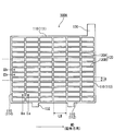
- FIG. 1A and 1B are plan views showing the appearance of current collectors 100A and 100B according to one embodiment and another embodiment of the present invention, respectively.
- Each of the current collectors 100A and 100B has a frame bone 110 and a mesh-like inner bone 120 inside the frame bone 110.
- the frame bone 110 includes an ear 130, an upper element 111 continuous with the ear 130, a lower element 112 facing the upper element 111, and a pair of side elements 113 and 114 connecting the upper element 111 and the lower element 112. Equipped with.
- the dashed line indicates the boundary that divides the internal bone into three equal parts: the upper region, the middle region, and the lower region.
- the transverse bone extends obliquely with respect to the upper element or the lower element.
- LH indicates the internal length per lattice of the vertical bone
- LW indicates the internal length per lattice of the lateral bone.
- the current collectors 100A and 100B are, for example, punched lattices of a lead or lead alloy stretched sheet, and the stretching direction is the direction indicated by the arrow MD in FIG.
- the cross section C of the vertical bone 120A is a cross section taken along the line IIa-IIa in FIG. 1
- the cross section G of the lateral bone 120B is a cross section taken along the line IIb-IIb.
- the metal structure of the stretched sheet tends to form a layered or fibrous structure extending in the stretching direction. Therefore, a striped pattern is formed on the cross section C.
- the cross section G may have a pattern formed by cutting a layered or fibrous structure.
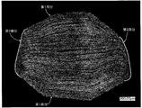
- FIG. 2A is an example of a photograph of the cross section C of the vertical bone 120A, and the cross section has an octagonal shape, and a striped pattern of metal fibrous tissue can be seen.
- FIG. 2B is a conceptual diagram of an example of an octagonal cross section C imitating FIG. 2A.
- FIG. 3 is an example of a photograph of the cross section G of the transverse bone 120B, and a pattern of the cross section perpendicular to the fiber length of the fibrous structure of the metal can be seen in the cross section.
- most of the left and right sides of the octagonal cross section C are the second portion 220, and the other outer peripheral region is the first portion 210.
- FIG. 4 is a conceptual diagram of a cross section C showing the progress of corrosion of the internal bone.
- the portion where the shallow corrosive layer is formed is the first portion where the fibrous structure extends along the contour of the cross section C, and it is difficult for the corrosive layer to be formed deeply even if the corrosion progresses. Therefore, peeling tends to occur near the interface between the current collector and the electrode material. Therefore, it is considered that the stress that the current collector tries to deform is easily relaxed.
- the portion where the wedge-shaped deep corrosive layer is formed is the second portion. When a deep corrosive layer is formed, non-uniform deformation of the current collector is likely to occur, the current collector is stretched, and the electrode material is likely to fall off.
- the positive electrode plate for a lead storage battery includes the above-mentioned current collector and a positive electrode material held by the current collector (positive electrode current collector).
- As the positive electrode plate what is called a paste type positive electrode plate is used.
- the positive electrode material is obtained by removing the positive electrode current collector from the positive electrode plate.
- a member such as a mat or pacing paper may be attached to the positive electrode plate. Since such a member (pasting member) is used integrally with the positive electrode plate, it is included in the positive electrode plate.
- the positive electrode plate includes such a member, the positive electrode material is the one excluding the positive electrode current collector and the sticking member. However, when a sticking member such as a mat is stuck to the separator, the thickness of the sticking member is included in the thickness of the separator.
- the positive electrode current collector is preferably a punched current collector.
- the current collector has a frame bone and an internal bone inside the frame bone.
- a grid-shaped current collector (positive electrode grid) is preferable.
- the inner bone portion has a lattice shape (including a mesh shape). By using the positive electrode lattice, it becomes easy to support the positive electrode material.
- the frame bone is preferably rectangular. The rectangle does not have to be a strict rectangle, and the vertices may be slightly rounded or each side may be slightly bent.
- the positive electrode current collector can be formed by press punching a lead or lead alloy sheet.
- the sheet is preferably a stretched sheet (also referred to as a rolled plate) that has been stretched.
- the stretched sheet may be a uniaxially stretched sheet or a biaxially stretched sheet.
- the lead alloy used for the positive electrode current collector a Pb—Sb alloy, a Pb—Ca alloy, a Pb—Ca—Sn alloy, or a Pb—Sn alloy is preferable in terms of corrosion resistance and mechanical strength. Further, lead having a purity equal to or higher than that of three nines (purity of 99.9% by mass or higher) may be used for the positive electrode current collector.
- the positive electrode current collector may include a surface layer. It may have lead alloy layers (surface layers) having different compositions, and may have a plurality of alloy layers. The composition of the surface layer and the inner layer of the positive electrode current collector may be different. The surface layer may be formed on a part of the positive electrode current collector. The surface layer may be formed only on the lattice portion of the positive electrode current collector or only on the frame bone portion (only the ear portion, only the frame bone portion other than the ear, etc.).
- the positive electrode material contains a positive electrode active material (lead dioxide or lead sulfate) whose capacity is developed by a redox reaction.
- the positive electrode material may contain additives, if necessary.
- the unchemical paste type positive electrode plate is obtained by filling the positive electrode current collector with the positive electrode paste, aging and drying.
- the positive electrode paste is prepared by kneading lead powder, additives, water, and sulfuric acid. Then, a positive electrode plate is obtained by forming these unchemicald positive electrode plates.
- the chemical conversion can be carried out by charging the electrode plate group in a state where the electrode plate group including the unchemical positive electrode plate is immersed in the electrolytic solution containing sulfuric acid in the electric tank of the lead storage battery. However, chemical conversion may be performed before assembling the lead-acid battery or the electrode plate group.
- the negative electrode plate of a lead storage battery is composed of a current collector and a negative electrode material.
- the negative electrode electrode material is a negative electrode plate obtained by removing the negative electrode current collector.
- a member such as a mat or pacing paper may be attached to the negative electrode plate. Since such a member (pasting member) is used integrally with the negative electrode plate, it is included in the negative electrode plate.
- the negative electrode material is the one excluding the negative electrode current collector and the sticking member.
- the negative electrode current collector may be formed by casting lead (Pb) or a lead alloy, or may be formed by processing a sheet of lead or a lead alloy. Examples of the processing method include expanding processing and punching processing. It is preferable to use a grid-shaped current collector (negative electrode lattice) as the negative electrode current collector because it is easy to support the negative electrode material. As the negative electrode current collector, a current collector as described for the positive electrode current collector may be used.
- the lead alloy used for the negative electrode current collector may be any of Pb-Sb-based alloys, Pb-Ca-based alloys, and Pb-Ca-Sn-based alloys. These leads or lead alloys may further contain, as an additive element, at least one selected from the group consisting of Ba, Ag, Al, Bi, As, Se, Cu and the like.
- the negative electrode current collector may include a surface layer. The surface layer and the inner layer of the negative electrode current collector may have different compositions. The surface layer may be formed on a part of the negative electrode current collector. The surface layer may be formed on the ears of the negative electrode current collector. The surface layer of the ear may contain Sn or a Sn alloy.
- the negative electrode material contains a negative electrode active material (lead or lead sulfate) whose capacity is developed by a redox reaction as an essential component, and may contain additives (organic shrink-proofing agent, carbonaceous material, barium sulfate, etc.).
- the negative electrode active material in the charged state is spongy lead, but the unchemicald negative electrode plate is usually produced using lead powder.
- lignins include lignin and lignin derivatives.
- lignin derivative include lignin sulfonic acid or a salt thereof (alkali metal salt (sodium salt, etc.), etc.).
- the synthetic organic shrinkage proofing agent is an organic polymer containing a sulfur element, and generally contains a plurality of aromatic rings in the molecule and also contains a sulfur element as a sulfur-containing group.
- a sulfonic acid group or a sulfonyl group in a stable form is preferable.
- the sulfonic acid group may be present in the acid form or in the salt form such as the Na salt.
- a condensate made of an aldehyde compound (aldehyde or a condensate thereof, for example, formaldehyde) of a compound having a sulfur-containing group and an aromatic ring is preferable.
- the aromatic ring include a benzene ring and a naphthalene ring.
- the plurality of aromatic rings may be directly bonded or linked by a linking group (for example, an alkylene group, a sulfone group, etc.). Examples of such a structure include biphenyl, bisphenyl alkane, bisphenyl sulfone and the like.
- Examples of the compound having an aromatic ring include the above-mentioned compound having an aromatic ring and a hydroxy group and / or an amino group.
- the hydroxy group or amino group may be directly bonded to the aromatic ring, or may be bonded as an alkyl chain having a hydroxy group or amino group.
- a bisphenol compound, a hydroxybiphenyl compound, a hydroxynaphthalene compound, a phenol compound and the like are preferable.
- the compound having an aromatic ring may further have a substituent.
- the organic shrinkage proofing agent may contain one type of residues of these compounds, or may contain a plurality of types.
- bisphenol compound bisphenol A, bisphenol S, bisphenol F and the like are preferable.
- the sulfur-containing group may be directly bonded to the aromatic ring contained in the compound, or may be bonded to the aromatic ring as an alkyl chain having a sulfur-containing group, for example.
- a condensate of the above compound having an aromatic ring and a monocyclic aromatic compound (aminobenzene sulfonic acid, alkylaminobenzene sulfonic acid, phenol sulfonic acid or a substitute thereof, etc.) with an aldehyde compound can be obtained.
- a condensate of the above compound having an aromatic ring and a monocyclic aromatic compound (aminobenzene sulfonic acid, alkylaminobenzene sulfonic acid, phenol sulfonic acid or a substitute thereof, etc.) with an aldehyde compound.
- an aldehyde compound May be used as an organic shrinkage proofing agent.
- the content of the organic shrink-proofing agent contained in the negative electrode electrode material is, for example, 0.01% by mass or more, and may be 0.02% by mass or more or 0.05% by mass or more.
- the content of the organic shrink-proofing agent is, for example, 1.0% by mass or less, and may be 0.8% by mass or less or 0.5% by mass or less.
- carbon black As the carbonaceous material contained in the negative electrode material, carbon black, graphite, hard carbon, soft carbon and the like can be used.
- carbon black examples include acetylene black, furnace black, and lamp black.
- Furness Black also includes Ketjen Black (trade name).
- the graphite may be any carbon material containing a graphite-type crystal structure, and may be either artificial graphite or natural graphite.
- the content of the carbonaceous material in the negative electrode material is, for example, 0.05% by mass or more, and may be 0.2% by mass or more.
- the content of the carbonaceous material is, for example, 4.0% by mass or less, and may be 3% by mass or less or 2% by mass or less.
- the content of barium sulfate in the negative electrode electrode material is, for example, 0.5% by mass or more, and may be 1% by mass or more or 1.3% by mass or more.
- the content of barium sulfate is, for example, 3.0% by mass or less, and may be 2.5% by mass or less or 2% by mass or less.
- the method for quantifying the organic shrinkage-proofing agent, carbonaceous material, and barium sulfate contained in the negative electrode material will be described below.
- the lead-acid battery after chemical conversion is fully charged and then disassembled to obtain the negative electrode plate to be analyzed.
- the obtained negative electrode plate is washed with water to remove sulfuric acid from the negative electrode plate. Washing with water is performed by pressing the pH test paper against the surface of the negative electrode plate washed with water until it is confirmed that the color of the test paper does not change. However, the time for washing with water shall be within 2 hours.
- the negative electrode plate washed with water is dried at 60 ⁇ 5 ° C. for about 6 hours in a reduced pressure environment.
- sample A a sample (hereinafter referred to as sample A) is obtained by separating the negative electrode material from the negative electrode plate. Sample A is pulverized as needed.
- the pulverized sample A is immersed in a 1 mol / L NaOH aqueous solution to extract an organic shrinkage proofing agent.
- the insoluble components are removed by filtration from the extracted NaOH aqueous solution containing the organic shrinkage proofing agent.
- the obtained filtrate (hereinafter, also referred to as filtrate B) is desalted, concentrated, and dried to obtain a powder of an organic shrink-proofing agent (hereinafter, also referred to as sample C).
- Desalination is carried out using a desalting column, by passing the filtrate B through an ion exchange membrane, or by placing the filtrate B in a dialysis tube and immersing it in distilled water.
- the organic shrink-proofing agent is specified by combining the information obtained from the thermal decomposition GC-MS or the like, which can obtain the information of the individual compounds.
- the content of the organic shrink-proofing agent in the negative electrode material is quantified using the spectral intensity and the calibration curve prepared in advance. If the structural formula of the organic shrink-proofing agent to be analyzed cannot be specified exactly and the calibration curve of the same organic shrinkage-proofing agent cannot be used, the ultraviolet-visible absorption spectrum and infrared spectroscopic spectrum similar to those of the organic shrinkage-proofing agent to be analyzed, A calibration curve is prepared using an available organic shrink-proofing agent showing an NMR spectrum or the like.
- a carbonaceous material and components other than barium sulfate are removed from the dispersion liquid using a sieve.
- the dispersion is suction-filtered using a membrane filter whose mass has been measured in advance, and the membrane filter is dried together with the filtered sample in a dryer at 110 ° C. ⁇ 5 ° C.
- the obtained sample is a mixed sample of a carbonaceous material and barium sulfate (hereinafter, also referred to as sample D).
- sample D a mixed sample of a carbonaceous material and barium sulfate
- the dried sample D is put into a crucible together with a membrane filter and incinerated at 700 ° C. or higher.
- the remaining residue is barium oxide.
- the mass of the barium oxide is converted to the mass of the barium sulfate determining the mass of barium sulfate (M B). Calculating the mass of the carbonaceous material from the mass M m by subtracting the mass M B.
- the negative electrode plate can be formed by filling a negative electrode current collector with a negative electrode paste, aging and drying to prepare an unchemicald negative electrode plate, and then forming an unchemicald negative electrode plate.
- the negative electrode paste is prepared by adding water and sulfuric acid to lead powder and various additives and kneading them. In the aging step, it is preferable to ripen the unchemicald negative electrode plate at room temperature or at a higher temperature and high humidity.
- Chemical formation can be performed by charging the electrode plate group in a state where the electrode plate group including the unchemical negative electrode plate is immersed in the electrolytic solution containing sulfuric acid in the cell of the lead storage battery. However, chemical conversion may be performed before assembling the lead-acid battery or the electrode plate group. The chemical formation produces spongy lead.
- a separator is usually arranged between the negative electrode plate and the positive electrode plate.
- a non-woven fabric, a microporous membrane, or the like is used as the separator.
- the thickness of the separator interposed between the negative electrode plate and the positive electrode plate may be selected according to the distance between the electrodes.
- the number of separators may be selected according to the number of poles.
- Nonwoven fabric is a mat that is entwined without weaving fibers, and is mainly composed of fibers.
- the non-woven fabric for example, 60% by mass or more of the non-woven fabric is formed of fibers.
- the fiber glass fiber, polymer fiber (polyolefin fiber, acrylic fiber, polyester fiber (polyethylene terephthalate fiber, etc.), etc.), pulp fiber, and the like can be used. Of these, glass fiber is preferable.
- the non-woven fabric may contain components other than fibers, for example, an acid-resistant inorganic powder and a polymer as a binder.
- the microporous film is a porous sheet mainly composed of components other than fiber components.
- a composition containing a pore-forming agent at least one of a polymer powder and an oil
- the microporous membrane is preferably composed of a material having acid resistance, and preferably contains a polymer component as a main component.
- polymer component polyolefin (polyethylene, polypropylene, etc.) is preferable.
- the separator may be composed of, for example, only a non-woven fabric or only a microporous membrane. Further, the separator may be a laminate of a non-woven fabric and a microporous film, a material obtained by laminating different or similar materials, or a material in which irregularities are engaged with different or similar materials, as required.
- the separator may be in the shape of a sheet or in the shape of a bag.
- a single sheet-shaped separator may be sandwiched between the positive electrode plate and the negative electrode plate.
- the electrode plate may be arranged so as to be sandwiched between a single sheet-shaped separator in a bent state.
- the positive electrode plate sandwiched between the bent sheet-shaped separators and the negative electrode plate sandwiched between the bent sheet-shaped separators may be overlapped, and one of the positive electrode plate and the negative electrode plate may be sandwiched between the bent sheet-shaped separators. , May be overlapped with the other electrode plate.
- the sheet-shaped separator may be bent in a bellows shape, and the positive electrode plate and the negative electrode plate may be sandwiched between the bellows-shaped separators so that the separator is interposed between them.
- the separator may be arranged so that the bent portion is along the horizontal direction of the lead storage battery (for example, the bent portion is parallel to the horizontal direction), and is along the vertical direction. (For example, the separator may be arranged so that the bent portion is parallel to the vertical direction).
- recesses are alternately formed on both main surface sides of the separator.
- the positive electrode plate is formed only in the concave portion on one main surface side of the separator.
- a negative electrode plate is arranged (that is, a double separator is interposed between the adjacent positive electrode plate and the negative electrode plate).
- the separator is arranged so that the bent portion is along the vertical direction of the lead-acid battery, the positive electrode plate can be accommodated in the recess on one main surface side and the negative electrode plate can be accommodated in the recess on the other main surface side (that is,).
- a separator may be provided in a single layer between the adjacent positive electrode plate and the negative electrode plate.)
- the bag-shaped separator may accommodate a positive electrode plate or a negative electrode plate.
- the vertical direction is defined with the side on which the ear is provided as the upper side and the side opposite to the ear as the lower side.
- the vertical direction of the electrode plate may be the same as or different from the vertical direction of the lead storage battery. That is, the lead-acid battery may be installed vertically or horizontally.
- the electrolytic solution is an aqueous solution containing sulfuric acid, and may be gelled if necessary.
- the electrolyte may optionally include cations (eg, metal cations (such as at least one selected from sodium, lithium, magnesium, and aluminum ions) and anions (eg, anions other than sulfate anions (phosphoric acid)). Ions, etc.)) may be included.
- the specific gravity of the electrolytic solution in a fully charged lead-acid battery at 20 ° C. is, for example, 1.20 or more, and may be 1.25 or more.
- the specific gravity of the electrolytic solution in a fully charged lead-acid battery at 20 ° C. is, for example, 1.35 or less, and may be 1.32 or less.
- a lead-acid battery including the positive electrode plate including the current collector is manufactured by a manufacturing method including, for example, a step of preparing the current collector and a step of obtaining a positive electrode plate containing the current collector and the positive electrode material. Can be manufactured.
- the current collector is prepared by the above-mentioned method for manufacturing a current collector. More specifically, the current collector is prepared by, for example, a manufacturing method including the steps (i) to (iv) described above.
- the positive electrode plate can be manufactured by the procedure described in the section of the positive electrode plate.
- the lead-acid battery can be obtained by a manufacturing method including a step of assembling the lead-acid battery by accommodating the positive electrode plate, the negative electrode plate and the electrolytic solution obtained above in an electric tank.
- the separator is usually arranged so as to be interposed between the positive electrode plate and the negative electrode plate.
- the step of assembling the lead-acid battery may include, if necessary, a step of forming at least one of the positive electrode plate and the negative electrode plate after the step of accommodating the positive electrode plate, the negative electrode plate, and the electrolytic solution in the battery case.
- the negative electrode plate, the electrolytic solution, and the separator are each prepared before being housed in the battery case.
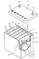
- FIG. 5 shows the appearance of an example of the lead storage battery according to the embodiment of the present invention.
- the lead-acid battery 1 includes an electric tank 12 that houses a electrode plate group 11 and an electrolytic solution (not shown).
- the inside of the electric tank 12 is partitioned into a plurality of cell chambers 14 by a partition wall 13. In each cell chamber 14, one electrode plate group 11 is stored.
- the opening of the battery case 12 is closed by a lid 15 including a negative electrode terminal 16 and a positive electrode terminal 17.
- the lid 15 is provided with a liquid spout 18 for each cell chamber. At the time of refilling water, the liquid spout 18 is removed and the refilling liquid is replenished.
- the liquid spout 18 may have a function of discharging the gas generated in the cell chamber 14 to the outside of the battery.
- the electrode plate group 11 is formed by laminating a plurality of negative electrode plates 2 and positive electrode plates 3 via a separator 4, respectively.
- the bag-shaped separator 4 accommodating the negative electrode plate 2 is shown, but the form of the separator is not particularly limited.
- the negative electrode shelf portion 6 for connecting the plurality of negative electrode plates 2 in parallel is connected to the through connecting body 8, and the positive electrode shelf portion for connecting the plurality of positive electrode plates 3 in parallel. 5 is connected to the positive electrode column 7.
- the positive electrode column 7 is connected to the positive electrode terminal 17 outside the lid 15.
- the negative electrode column 9 is connected to the negative electrode shelf 6, and the through connector 8 is connected to the positive electrode shelf 5.
- the negative electrode column 9 is connected to the negative electrode terminal 16 outside the lid 15.
- Each through-connecting body 8 passes through a through-hole provided in the partition wall 13 and connects the electrode plates 11 of the adjacent cell chambers 14 in series.
- the positive electrode shelf 5 is formed by welding the ears provided on the upper part of each positive electrode plate 3 by a cast-on strap method or a burning method.
- the negative electrode shelf portion 6 is also formed by welding the ears provided on the upper portions of the negative electrode plates 2 as in the case of the positive electrode shelf portion 5.
- the lid 15 of the lead storage battery has a single structure (single lid), but is not limited to the case shown in the illustrated example.
- the lid 15 may have, for example, a double structure including an inner lid and an outer lid (or upper lid).
- the lid having a double structure is provided with a reflux structure between the inner lid and the outer lid for returning the electrolytic solution to the inside of the battery (inside the inner lid) from the reflux port provided on the inner lid. May be good.
- FIG. 5 shows an example of a liquid battery (vent type battery)
- the lead storage battery may be a control valve type battery (VRLA type).
- VRLA type control valve type battery
- test battery (A) First single plate overcharge test Using a predetermined test battery, an overcharge test with a constant current of 1.7 A (current density: 0.0054 A / cm 2 ) was performed for 5 days in a water tank at 75 ° C ⁇ 2 ° C. After that, the operation of resting for 2 days (1 week) is repeated for 3 weeks.
- the apparent current collector area when calculating the current density is twice the product of the height and width of the outer frame of the positive electrode current collector.
- the following evaluation (a) or (b) is performed on the positive electrode current collector taken out from the fully charged test battery.
- the positive electrode current collector used for the evaluation is prepared by being taken out from the test battery, washed with water, dried, and the electrode material is removed, as in the case of the current collector when forming the cross section C.
- Corrosion rate (%) ⁇ (mass of positive electrode current collector before overcharge test-mass of positive electrode current collector with corrosive layer removed by mannitting after overcharge test) ⁇ (positive electrode current collector before overcharge test) Body mass) ⁇ x 100
- Width elongation and height elongation of the positive electrode current collector Measure the dimensions of the most bulging portion of the frame bone of the positive electrode current collector in the first direction (height direction) and the second direction (width direction), respectively. , Find the width elongation and height elongation compared to the initial dimensions.
- the dimensions of the most bulging part of the frame bone in the second direction (width direction) of the positive electrode current collector taken out from the fully charged test battery were measured and compared with the initial dimensions. To find the amount of width elongation.
- the positive electrode current collector used for the evaluation is prepared by being taken out from the test battery, washed with water, dried, and the electrode material is removed, as in the case of the current collector when forming the cross section C.
- Lead-acid batteries A11 to A13, B11 to B13, and B21 to B26 >> (1) Preparation of lead-acid battery (a) Preparation of current collector The rolled sheet of Pb-Ca—Sn alloy is punched, the inner bone is pressed, and the current collectors a11 to a13 and b11 to shown in Table 1 are pressed. b13 and b21 to b26 are obtained, respectively. At this time, the ratio R1 is adjusted by adjusting the press speed and the press pressure. The ratio W1 / W2 is adjusted by adjusting the ratio of the portion removed by punching and the remaining portion when punching the rolled sheet.
- the thickness of the internal bone is 0.95 mm
- the width of the frame bone is 1.0 mm
- the WLH / WLW is 1.37.
- the WLH / WLW of the current collectors a11 and a13 are both 1.3 or more.
- test battery X A lead-acid battery (test battery X: rated voltage 2V, rated 5-hour rate capacity 6Ah) is assembled using an unchemical positive electrode plate containing a positive electrode current collector and a positive electrode material.
- the test battery X is composed of one unchemical positive electrode plate and two unchemical negative electrode plates sandwiching the positive electrode plate, and is chemically formed in an electrolytic solution.
- the negative electrode plate is housed in a bag-shaped separator.
- An aqueous sulfuric acid solution is used as the electrolytic solution. After chemical conversion, the specific gravity of the electrolytic solution at 20 ° C. is adjusted to 1.28 in the fully charged test battery.
- Lead-acid batteries A31 to A33 and B31 >> (1) Preparation of lead-acid battery
- the current collectors a31 to a33 and b31 shown in Table 2 are manufactured.
- the ratio R1 and the ratio W1 / W2 are adjusted in the same manner as in the case of the lead storage battery A11.
- a lead storage battery (test battery Y) is assembled using the obtained current collector without supporting the positive electrode material.
- As the electrolytic solution an aqueous sulfuric acid solution having a specific gravity of 1.28 at 20 ° C. is used.
- the test battery Y is assembled in the same manner as in the case of the lead storage battery A11.
- the test battery Y is composed of one positive electrode current collector, two ready-made negative electrode plates sandwiching the positive electrode current collector, and an electrolytic solution.
- the negative electrode plate is housed in a bag-shaped separator.
- FIG. 7 shows the relationship between the ratio R1, the corrosion rate, and the amount of deformation (width elongation, height elongation of the current collector) with respect to the current collectors a31 to a33 and b31.
- the corrosion rate does not change so much, the height elongation is suppressed when the ratio R1 is 50% or more, and the height elongation and width are suppressed when the ratio R1 is 60% or more. Both elongation are greatly suppressed.
- the ratio R1 may be 75% or more or 80% or more.
- Lead-acid batteries A41-A47 (1) Preparation of lead-acid battery
- the current collectors a41 to a47 shown in Table 3 are manufactured.
- the ratio R1 and the ratio W1 / W2 are adjusted in the same manner as in the case of the lead storage battery A11.
- the obtained current collector is used as a positive electrode current collector and a negative electrode current collector to produce an unchemicald positive electrode plate and a negative electrode plate in the same manner as in the case of the lead storage battery A11.
- a lead storage battery (test battery Z) is assembled using the obtained unchemical positive electrode plate and negative electrode plate.
- the unchemical negative electrode plate is housed in a bag-shaped separator, and an electrode group is formed by eight unchemical negative electrode plates and eight unchemical positive electrode plates.
- a group of electrode plates is housed in a polypropylene electric tank together with an electrolytic solution, and chemical conversion is performed in the electric tank to prepare a test battery Z (12 V, rated 5-hour rate capacity 48 Ah).
- An aqueous sulfuric acid solution is used as the electrolytic solution.
- the specific gravity of the electrolytic solution at 20 ° C. is adjusted to 1.28 in the fully charged test battery.
- Lead-acid batteries A51 to A54 and B51 to B54 >> (1) Preparation of lead-acid battery The current collectors a51 to a54 and b51 to b54 shown in Table 4 are prepared. The ratio R1 and the ratio W1 / W2 are adjusted in the same manner as in the case of the lead storage battery A11. The ratio WLH / WLW is adjusted by adjusting the press speed and press pressure. The obtained current collectors are used as the positive electrode current collector and the negative electrode current collector to prepare lead-acid batteries A51 to A54 and B51 to B54 (test battery X) in the same manner as in the case of the lead-acid battery A11.
- the lead-acid battery current collector according to the present invention is applicable to control valve type and liquid type lead-acid batteries.
- a lead-acid battery provided with an electrode plate including a current collector can be suitably used as a power source for starting a vehicle (automobile, motorcycle, etc.) and a power source for an industrial power storage device (electric vehicle (forklift, etc.)). It should be noted that these uses are merely examples and are not limited to these uses.
- Negative electrode plate 3 Positive electrode plate 4: Separator 5: Positive electrode shelf part 6: Negative electrode shelf part 7: Positive electrode pillar 8: Through connector 9: Negative electrode pillar 11: Electrode plate group 12: Electric tank 13: Partition 14: Cell chamber 15: Lid 16: Negative electrode terminal 17: Positive electrode terminal 18: Liquid port plug 100A, 100B: Current collector 110: Frame bone 111: Upper element 112: Lower element 113, 114: Side element 120: Inner bone 120A, B1: Vertical bone 120B: Horizontal bone 130: Ear 132: Lower electrode (foot) 210: First part of the longitudinal bone 220: Second part of the longitudinal bone
Landscapes
- Chemical & Material Sciences (AREA)
- Chemical Kinetics & Catalysis (AREA)
- Electrochemistry (AREA)
- General Chemical & Material Sciences (AREA)
- Engineering & Computer Science (AREA)
- Materials Engineering (AREA)
- Cell Electrode Carriers And Collectors (AREA)
Priority Applications (3)
| Application Number | Priority Date | Filing Date | Title |
|---|---|---|---|
| EP21789338.7A EP4095952A4 (en) | 2020-04-14 | 2021-01-29 | CURRENT COLLECTOR FOR LEAD-ACID BATTERY, POSITIVE ELECTRODE PLATE FOR LEAD-ACID BATTERY, AND LEAD-ACID BATTERY |
| JP2022515212A JP7601092B2 (ja) | 2020-04-14 | 2021-01-29 | 鉛蓄電池用集電体、鉛蓄電池用正極板、および鉛蓄電池 |
| CN202180028448.2A CN115428197A (zh) | 2020-04-14 | 2021-01-29 | 铅蓄电池用集电体、铅蓄电池用正极板及铅蓄电池 |
Applications Claiming Priority (2)
| Application Number | Priority Date | Filing Date | Title |
|---|---|---|---|
| JP2020072059 | 2020-04-14 | ||
| JP2020-072059 | 2020-04-14 |
Publications (1)
| Publication Number | Publication Date |
|---|---|
| WO2021210244A1 true WO2021210244A1 (ja) | 2021-10-21 |
Family
ID=78084207
Family Applications (1)
| Application Number | Title | Priority Date | Filing Date |
|---|---|---|---|
| PCT/JP2021/003250 Ceased WO2021210244A1 (ja) | 2020-04-14 | 2021-01-29 | 鉛蓄電池用集電体、鉛蓄電池用正極板、および鉛蓄電池 |
Country Status (4)
| Country | Link |
|---|---|
| EP (1) | EP4095952A4 (https=) |
| JP (1) | JP7601092B2 (https=) |
| CN (1) | CN115428197A (https=) |
| WO (1) | WO2021210244A1 (https=) |
Citations (8)
| Publication number | Priority date | Publication date | Assignee | Title |
|---|---|---|---|---|
| JPS5160936A (ja) | 1974-11-01 | 1976-05-27 | Furukawa Electric Co Ltd | Namarichikudenchonamarikoshiban |
| JPH0554893A (ja) | 1991-08-28 | 1993-03-05 | Shin Kobe Electric Mach Co Ltd | 鉛蓄電池用格子体 |
| JPH06267544A (ja) * | 1993-03-12 | 1994-09-22 | Matsushita Electric Ind Co Ltd | 鉛蓄電池用極板とこれを用いた鉛蓄電池 |
| JP2012174561A (ja) | 2011-02-23 | 2012-09-10 | Shin Kobe Electric Mach Co Ltd | 正極格子基板、この正極格子基板を用いた極板及びこの極板を用いた鉛蓄電池 |
| WO2015056417A1 (ja) * | 2013-10-15 | 2015-04-23 | 株式会社Gsユアサ | 制御弁式鉛蓄電池 |
| JP2017139215A (ja) * | 2016-02-02 | 2017-08-10 | 株式会社Gsユアサ | 鉛蓄電池用の正極板、鉛蓄電池、鉛蓄電池用の正極板の製造方法 |
| WO2020080419A1 (ja) * | 2018-10-16 | 2020-04-23 | 株式会社Gsユアサ | 鉛蓄電池 |
| WO2020080422A1 (ja) * | 2018-10-16 | 2020-04-23 | 株式会社Gsユアサ | 鉛蓄電池、および、鉛蓄電池の製造方法 |
Family Cites Families (1)
| Publication number | Priority date | Publication date | Assignee | Title |
|---|---|---|---|---|
| US20170222214A1 (en) * | 2016-02-02 | 2017-08-03 | Gs Yuasa International, Ltd. | Positive electrode plate for lead-acid battery, lead-acid battery and method of manufacturing positive electrode plate for lead-acid battery |
-
2021
- 2021-01-29 EP EP21789338.7A patent/EP4095952A4/en active Pending
- 2021-01-29 CN CN202180028448.2A patent/CN115428197A/zh active Pending
- 2021-01-29 WO PCT/JP2021/003250 patent/WO2021210244A1/ja not_active Ceased
- 2021-01-29 JP JP2022515212A patent/JP7601092B2/ja active Active
Patent Citations (8)
| Publication number | Priority date | Publication date | Assignee | Title |
|---|---|---|---|---|
| JPS5160936A (ja) | 1974-11-01 | 1976-05-27 | Furukawa Electric Co Ltd | Namarichikudenchonamarikoshiban |
| JPH0554893A (ja) | 1991-08-28 | 1993-03-05 | Shin Kobe Electric Mach Co Ltd | 鉛蓄電池用格子体 |
| JPH06267544A (ja) * | 1993-03-12 | 1994-09-22 | Matsushita Electric Ind Co Ltd | 鉛蓄電池用極板とこれを用いた鉛蓄電池 |
| JP2012174561A (ja) | 2011-02-23 | 2012-09-10 | Shin Kobe Electric Mach Co Ltd | 正極格子基板、この正極格子基板を用いた極板及びこの極板を用いた鉛蓄電池 |
| WO2015056417A1 (ja) * | 2013-10-15 | 2015-04-23 | 株式会社Gsユアサ | 制御弁式鉛蓄電池 |
| JP2017139215A (ja) * | 2016-02-02 | 2017-08-10 | 株式会社Gsユアサ | 鉛蓄電池用の正極板、鉛蓄電池、鉛蓄電池用の正極板の製造方法 |
| WO2020080419A1 (ja) * | 2018-10-16 | 2020-04-23 | 株式会社Gsユアサ | 鉛蓄電池 |
| WO2020080422A1 (ja) * | 2018-10-16 | 2020-04-23 | 株式会社Gsユアサ | 鉛蓄電池、および、鉛蓄電池の製造方法 |
Non-Patent Citations (1)
| Title |
|---|
| See also references of EP4095952A4 |
Also Published As
| Publication number | Publication date |
|---|---|
| CN115428197A (zh) | 2022-12-02 |
| EP4095952A1 (en) | 2022-11-30 |
| JP7601092B2 (ja) | 2024-12-17 |
| JPWO2021210244A1 (https=) | 2021-10-21 |
| EP4095952A4 (en) | 2024-10-09 |
Similar Documents
| Publication | Publication Date | Title |
|---|---|---|
| JP7347438B2 (ja) | 鉛蓄電池 | |
| WO2020080422A1 (ja) | 鉛蓄電池、および、鉛蓄電池の製造方法 | |
| WO2019188056A1 (ja) | 鉛蓄電池 | |
| JP7424310B2 (ja) | 鉛蓄電池 | |
| JP7318660B2 (ja) | 鉛蓄電池 | |
| JP7347439B2 (ja) | 鉛蓄電池 | |
| JP7264175B2 (ja) | 鉛蓄電池 | |
| JPWO2019021690A1 (ja) | 鉛蓄電池 | |
| JP7248033B2 (ja) | 鉛蓄電池およびその製造方法 | |
| WO2021210244A1 (ja) | 鉛蓄電池用集電体、鉛蓄電池用正極板、および鉛蓄電池 | |
| JP7452429B2 (ja) | 鉛蓄電池用集電体およびその製造方法 | |
| JP2021103630A (ja) | 蓄電池用集電体および電極板 | |
| JP7797970B2 (ja) | 鉛蓄電池 | |
| EP4525129A1 (en) | Lead-acid battery | |
| WO2023210636A1 (ja) | 鉛蓄電池 | |
| CN121693815A (zh) | 液式铅蓄电池 | |
| JP2021192352A (ja) | 鉛蓄電池 |
Legal Events
| Date | Code | Title | Description |
|---|---|---|---|
| 121 | Ep: the epo has been informed by wipo that ep was designated in this application |
Ref document number: 21789338 Country of ref document: EP Kind code of ref document: A1 |
|
| ENP | Entry into the national phase |
Ref document number: 2022515212 Country of ref document: JP Kind code of ref document: A |
|
| ENP | Entry into the national phase |
Ref document number: 2021789338 Country of ref document: EP Effective date: 20220824 |
|
| NENP | Non-entry into the national phase |
Ref country code: DE |