WO2021210244A1 - Current collector for lead storage battery, positive electrode plate for lead storage battery, and lead storage battery - Google Patents
Current collector for lead storage battery, positive electrode plate for lead storage battery, and lead storage battery Download PDFInfo
- Publication number
- WO2021210244A1 WO2021210244A1 PCT/JP2021/003250 JP2021003250W WO2021210244A1 WO 2021210244 A1 WO2021210244 A1 WO 2021210244A1 JP 2021003250 W JP2021003250 W JP 2021003250W WO 2021210244 A1 WO2021210244 A1 WO 2021210244A1
- Authority
- WO
- WIPO (PCT)
- Prior art keywords
- current collector
- lead
- bone
- positive electrode
- electrode plate
- Prior art date
Links
Images


Classifications
-
- H—ELECTRICITY
- H01—ELECTRIC ELEMENTS
- H01M—PROCESSES OR MEANS, e.g. BATTERIES, FOR THE DIRECT CONVERSION OF CHEMICAL ENERGY INTO ELECTRICAL ENERGY
- H01M4/00—Electrodes
- H01M4/02—Electrodes composed of, or comprising, active material
- H01M4/64—Carriers or collectors
- H01M4/66—Selection of materials
- H01M4/68—Selection of materials for use in lead-acid accumulators
- H01M4/685—Lead alloys
-
- H—ELECTRICITY
- H01—ELECTRIC ELEMENTS
- H01M—PROCESSES OR MEANS, e.g. BATTERIES, FOR THE DIRECT CONVERSION OF CHEMICAL ENERGY INTO ELECTRICAL ENERGY
- H01M4/00—Electrodes
- H01M4/02—Electrodes composed of, or comprising, active material
- H01M4/64—Carriers or collectors
- H01M4/70—Carriers or collectors characterised by shape or form
- H01M4/72—Grids
- H01M4/73—Grids for lead-acid accumulators, e.g. frame plates
-
- Y—GENERAL TAGGING OF NEW TECHNOLOGICAL DEVELOPMENTS; GENERAL TAGGING OF CROSS-SECTIONAL TECHNOLOGIES SPANNING OVER SEVERAL SECTIONS OF THE IPC; TECHNICAL SUBJECTS COVERED BY FORMER USPC CROSS-REFERENCE ART COLLECTIONS [XRACs] AND DIGESTS
- Y02—TECHNOLOGIES OR APPLICATIONS FOR MITIGATION OR ADAPTATION AGAINST CLIMATE CHANGE
- Y02E—REDUCTION OF GREENHOUSE GAS [GHG] EMISSIONS, RELATED TO ENERGY GENERATION, TRANSMISSION OR DISTRIBUTION
- Y02E60/00—Enabling technologies; Technologies with a potential or indirect contribution to GHG emissions mitigation
- Y02E60/10—Energy storage using batteries
Definitions
- Lead-acid batteries are used for various purposes such as in-vehicle use and industrial use.
- the lead-acid battery includes a group of electrode plates in which positive electrode plates and negative electrode plates are alternately laminated via separators.
- the electrode plate is composed of a current collector and an electrode material held by the current collector.
- Patent Document 1 in a lead lattice plate obtained by press-punching a rolled plate of a lead alloy, the thickness of the inner vertical and horizontal crosspieces is made thinner than the thickness of the outer frame, and the thickness of the outer frame is 0.
- a lead grid plate for lead storage batteries which is characterized in that the thickness of the crosspiece is in the range of 8 to 1.5 mm and the thickness of the internal crosspiece is in the range of 0.6 to 0.8 mm.
- Cited Document 1 the inner frame of a lead lattice plate obtained by pressing and punching a rolled plate of a lead alloy having a thickness of 1.2 to 1.5 mm is deformed in the thickness direction to form the inner length and the inside.
- a lead grid plate for lead storage batteries which is characterized in that the thickness of the horizontal crosspiece is set in the range of 0.6 to 0.8 mm.
- Patent Document 2 includes a frame bone, an ear arranged outside the frame bone, and an internal bone arranged inside the frame bone and forming a lattice, and the additional mass of the frame bone and the ear ( The frame bone + ear) proposes a positive lattice substrate that is lighter than the mass of the internal bone.
- Patent Document 3 describes a lead storage battery lattice body having a frame bone and an inner bone composed of a plurality of horizontal rails and a plurality of vertical rails, and the upper end portions of the plurality of vertical rails are each on the upper side of the frame bone.
- the plurality of vertical crosspieces are connected to the bone and extend toward the lower transverse bone side of the frame bone so as not to intersect with each other, and the mass of the upper transverse bone of the frame bone is 11 of the mass of the entire lattice. % Or more and 14% or less, and the mass is distributed so that the total mass of the upper lateral bone and the mass of the plurality of vertical crosspieces is 60% or more and 70% or less of the total mass of the lattice body.
- Japanese Unexamined Patent Publication No. 51-60936 Japanese Unexamined Patent Publication No. 2012-174561 Japanese Unexamined Patent Publication No. 5-54893
- the outer peripheral region of the cross section is composed of a first portion in which the fibrous structure extends along the contour of the cross section and a second portion other than the first portion.
- the ratio of the length of the contour corresponding to the first portion to the total length of the contour of the cross section: R1 is 50% or more.
- the ratio of the mass W1 of the frame bone to the mass W2 of the inner bone: W1 / W2 is 0.2 ⁇ W1 / W2 ⁇ 0.42 Regarding the current collector for lead-acid batteries, which satisfies the above.
- the lead-acid battery current collector has a frame bone and an inner bone inside the frame bone.
- the frame bone comprises an ear, an upper element continuous with the ear, a lower element facing the upper element, and a pair of side elements connecting the upper element and the lower element.
- the internal bone comprises a longitudinal bone extending in the first direction from the upper element to the lower element and a transverse bone extending in the second direction from one side element to the other side element.
- a striped pattern of metal fibrous tissue can be seen in the cross section perpendicular to the first direction of the longitudinal bone.
- the outer peripheral region of the cross section is composed of a first portion in which the fibrous structure extends along the contour of the cross section and a second portion other than the first portion.
- the ratio of the length of the contour corresponding to the first portion to the total length of the contour of the cross section: R1 is 50% or more.
- the ratio of the mass W1 of the frame bone to the mass W2 of the inner bone: W1 / W2 satisfies 0.2 ⁇ W1 / W2 ⁇ 0.42.
- the current collector is also called a grid.
- the skeleton of the current collector or the grid is not limited to the grid or the mesh.
- the frame bone (more specifically, the portion of the frame bone excluding the ear portion) is usually generally rectangular, and may be rectangular.
- a quadrangle is a quadrangle in which at least one of the angles formed by the upper element and the pair of side elements and the angles formed by the lower element and the pair of side elements (a total of four angles) is not 90 ° C. It may be trapezoidal). At least one of the four corners of the quadrangle may be chamfered.
- the chamfer may be C chamfer or R chamfer. Usually, R chamfering with rounded corners is preferable.
- the first direction is the direction parallel to the side element
- the second direction is the direction parallel to the upper element and the lower element.
- the first direction corresponds to the vertical direction
- the second direction corresponds to the horizontal direction in the normal usage state of the lead-acid battery.
- the first direction corresponds to the vertical direction (or the horizontal direction)
- the second direction is horizontal in the normal usage state of the lead-acid battery. Corresponds to the direction (or vertical direction).
- the transverse bone may extend parallel to the upper or lower element, or may extend diagonally with respect to the upper or lower element. Further, the lateral bone may be straight or curved, and may have some bending. That is, the lateral bone may extend so that the vector toward the second direction is larger than the vector toward the first direction.
- cross section C In the cross section perpendicular to the first direction of the vertical bone, that is, the cross section parallel to the upper element and parallel to the thickness direction (hereinafter, also referred to as cross section C), a striped pattern of metal fibrous tissue can be seen.
- the outer peripheral region of the cross section C is composed of a first portion in which the fibrous structure (direction of stripes) extends along the contour of the cross section C and a second portion other than the first portion.
- the contour of the cross section C means a line corresponding to the outer surface of the vertical bone.
- the outer peripheral region of the cross section C is a peripheral region along the contour of the cross section C, and has a depth of at least 55 ⁇ m or more, preferably 100 ⁇ m or more from the line corresponding to the outer surface in the cross section C.
- the striped pattern may not be observed, and the striped pattern extending in the depth direction of the outer peripheral region may be observed.
- the ratio R1 is set to 50% or more, and the ratio W1 / W2 is controlled in the range of 0.2 or more and 0.42 or less.
- the ratio R1 is 50% or more, it means that the ratio R2 is 50% or less.
- the corrosion of the current collector proceeds preferentially in the cross section perpendicular to the fiber length of the fibrous tissue exposed on the outer surface.
- a fibrous metal structure extends in the plane direction of the inner bone. That is, the grain boundaries extend longer in the plane direction of the inner bone than in the depth direction of the inner bone. Therefore, the corrosive layer formed in the first portion of the outer peripheral region is formed along the surface direction of the inner bone, and is difficult to be formed to a deep position inside the inner bone.
- the corrosive layer formed along the outer surface of the first portion of the outer peripheral region has a low bonding strength with the current collector (inner bone).
- a fibrous metal tissue extends in the depth direction of the inner bone. That is, the grain boundaries extend longer in the depth direction of the inner bone than in the plane direction of the inner bone. Therefore, in the second part, the corrosion of the vertical bone tends to proceed deeply in a wedge shape, and the elongation of the current collector due to the deep corrosion tends to increase. Therefore, the corrosive layer formed along the outer surface of the second portion of the outer peripheral region has high bonding strength with the current collector (inner bone). In the second part, even if gas is generated at the interface between the current collector and the corroded layer, the corroded layer is difficult to peel off from the current collector.
- the current collector is likely to be stretched or deformed.
- a high temperature for example, a temperature of 60 ° C. or higher
- the current collector is more likely to be corroded, and gas generation becomes remarkable, so that the second part is corroded.
- the effect of stress from the layer is likely to become apparent. Therefore, even if the amount of corrosion is the same, the larger the ratio R1, the more the elongation and deformation of the current collector are suppressed, and the more the electrode material is suppressed from falling off.
- a cross section perpendicular to the second direction of the transverse bone of the current collector that is, a cross section parallel to the side elements and parallel to the thickness direction (hereinafter, also referred to as a cross section G) has a striped pattern of metal fibrous tissue. It is rarely seen, and generally a cross section perpendicular to the fiber length of the fibrous structure is seen.
- the outer peripheral region of the cross section G usually has almost the entire circumference corresponding to the second portion in the cross section C. That is, the outer peripheral region of the cross section G is composed of a fibrous structure whose entire circumference extends in the second direction. Therefore, in the outer peripheral region of the cross section G, the elongation or deformation of the current collector is suppressed even if the amount of corrosion is the same.
- the ratio W1 / W2 it becomes easy to secure the binding force of the electrode material, and the deformation of the internal bone can be suppressed to some extent.
- the current collector may extend in one direction, or the stress applied to the current collector may vary, causing distortion and bending.
- the deformation (elongation, curvature, etc.) of the current collector becomes remarkable.
- the initial capacity ratio of the capacity obtained by discharging about 5 cycles may be reduced to less than 70%.
- the ratio R1 is 95% or less
- the initial capacity ratio of the capacity around 5 cycles can be 75% or more or 80% or more.
- the first portion tends to form a layered shallow corrosive layer, and the second portion forms a wedge-shaped deep corrosive layer. Therefore, the binding force between the current collector and the electrode material is higher in the second portion than in the first portion. From the viewpoint of improving the binding force between the current collector and the electrode material, the ratio R2 of the second portion is preferably 5% or more, and more preferably 10% or more.
- the ratio R1 and the ratio R2 can be intentionally controlled.
- the ratio R1 can be arbitrarily controlled by the press speed, press pressure, mold shape, and the like. That is, deforming the vertical bone by press working is not a sufficient condition for increasing the ratio R1, and it is necessary to appropriately control the conditions of press working.
- the shape of the cross section C of the vertical bone is not particularly limited, but it is preferably octagonal.
- the cross section C is octagonal, the internal angle of the apex does not become too small, and the effect of suppressing corrosion near the apex can be easily enhanced.
- a vertical bone having an octagonal cross section C for example, a vertical bone having a rectangular cross section C may be deformed.
- the method of deforming the vertical bone is not particularly limited, but for example, the inner bone of the current collector may be press-processed. At that time, the pressing conditions of the internal bone may be appropriately selected so that the ratio R1 of the first portion falls within a predetermined range.
- the octagon does not have to be a strict octagon in the mathematical sense, and the vertices may be slightly rounded or each side may be slightly bent.
- the above aspect of the present invention is useful when a punched current collector is used as the current collector.
- a punched current collector of a lead or lead alloy drawn sheet is preferable. Since the stretched sheet tends to generate a striped pattern of a metallic fibrous structure, it becomes easy to adjust the ratio of the second portion.
- the fibrous structure (direction of stripes) extending along the contour of the outer peripheral region of the cross section C means the following state.
- the inside of the frame bone of the current collector is divided into three equal parts: an upper region on the upper element side of the frame bone, a lower region on the lower element side of the frame bone, and a middle region between the upper region and the lower region. Cut to be done.
- four rows of cross sections C perpendicular to the first direction are formed in the plurality of vertical bones. That is, one row of cross sections C is formed in each of the upper region and the lower region, and two rows of cross sections C are formed in the middle region.
- the dividing line into three equal parts corresponds to the intersection (node) between the vertical bone and the horizontal bone
- the dividing line is generally divided so that the cross section C is formed in the vertical bone portion between the intersections as much as possible.
- the current collector may be divided into three parts by partially moving the current collector.
- the portion where the fringes of the fibrous structure have an angle of less than 45 ° with the contour of the cross section C with respect to the horizontal plane in the first direction from the side element is the first portion.
- the second part is the second part. Specifically, at an arbitrary point P on the contour of each cross section C, a tangent line S1 of the point P is drawn, and a perpendicular line L of the tangent line S1 is drawn so as to pass through the point P.
- a tangent line S2 of a stripe existing at a depth of 55 ⁇ m from the point P on the perpendicular line L and intersecting the perpendicular line L is drawn at the intersection.
- the angle ⁇ between the tangent line S2 and the tangent line S1 is less than 45 °
- the point P constitutes the contour corresponding to the first portion.
- the angle ⁇ is 45 ° or more
- the point P constitutes the contour corresponding to the second portion. Even when it is not possible to determine whether or not the point P constitutes the contour corresponding to the first portion because the fibrous structure cannot be observed, the point P constitutes the contour of the second portion.
- the ratio R1 is calculated by obtaining and averaging the ratio of the length of the contour corresponding to the first portion to the total length of the contour of the cross section C.
- the ratio R2 (%) of the second portion is a value obtained by subtracting the average value of the ratio R1 (%) of the first portion from 100.
- the cross section C When forming the cross section C, it is embedded in a thermosetting resin so as to cover the entire prepared current collector, the resin is cured, and then the current collector is cut together with the cured resin. The state of the metal structure of the cross section C is photographed and observed with a microscope after the cross section of the current collector is etched. As the current collector, a current collector taken out by disassembling a fully charged lead-acid battery is used.
- the current collector can be removed from the battery by the following procedure. First, the electrode plate (positive electrode plate, etc.) taken out by disassembling the fully charged lead-acid battery is washed with water to remove the electrolytic solution containing sulfuric acid and dried. After that, most of the electrode material is scraped off from the electrode plate. The remaining positive electrode material adhering to the surface of the current collector is removed with an aqueous solution containing mannitol. A current collector for measurement is prepared by washing and drying the current collector from which the electrode material has been removed.
- the fully charged state of the liquid lead-acid battery is defined by the definition of JIS D 5301: 2006. More specifically, in a water tank at 25 ° C. ⁇ 2 ° C., the lead-acid battery is being charged with a current (A) of 0.2 times the value described as the rated capacity (Ah) measured every 15 minutes.
- a fully charged state is defined as a state in which the terminal voltage or the electrolyte density converted into a temperature of 20 ° C. is charged three times in a row until it shows a constant value with three significant figures.
- the fully charged state means that the lead-acid battery has a current (A) 0.2 times the value described as the rated capacity (Ah) in the air tank at 25 ° C ⁇ 2 ° C. ), Constant current constant voltage charging of 2.23V / cell is performed, and charging ends when the charging current (A) during constant voltage charging becomes 0.005 times the value described as the rated capacity (Ah). It is in a state of being.
- the numerical value described as the rated capacity is a numerical value in which the unit is Ah.
- the unit of current set based on the numerical value described as the rated capacity is A.
- a fully charged lead-acid battery is a fully charged lead-acid battery.
- the lead-acid battery may be fully charged after the chemical conversion, immediately after the chemical conversion, or after a lapse of time from the chemical conversion (for example, after the chemical conversion, the lead-acid battery in use (preferably at the initial stage of use) is fully charged. May be).
- An initial use battery is a battery that has not been used for a long time and has hardly deteriorated.
- the mass W1 of the frame bone and the mass W2 of the inner bone are measured for the current collector taken out from the fully charged lead-acid battery, respectively.
- the current collector prepared for the measurement Prior to the measurement of W1 and W2, the current collector prepared for the measurement is separated into the frame bone and the internal bone by cutting the boundary portion between the frame bone and the internal bone.
- the thickness of the first portion (in other words, the thickness of the fibrous structure) may be 55 ⁇ m or more. Further, even if the outer peripheral region looks like the first portion at first glance, if the thickness of the region where the striped pattern of the fibrous structure is observed is less than 55 ⁇ m, it is regarded as the second portion instead of the first portion.
- the first portion having a thickness of 55 ⁇ m or more has a sufficient effect of suppressing the entry of corrosion into the inner bone. In this case, the inward penetration of corrosion tends to be highly uniform throughout the internal bone. Therefore, the elongation and strain of the current collector are remarkably suppressed, and the dropout of the electrode material is also remarkably suppressed. From the viewpoint of further suppressing the intrusion of vertical bone corrosion into the inside, the thickness of the first portion is preferably 100 ⁇ m or more.
- the thickness of the first portion in the cross section C may be measured as follows. First, a tangent line S1 is drawn at an arbitrary point P1 on the contour of the first portion, and a perpendicular line L of the tangent line S1 is drawn so as to pass through the point P1. Next, at the point Px that moves on the perpendicular line L from the point P1 to a depth of X ⁇ m, the tangent line S2 of the stripe that intersects the perpendicular line L is continuously drawn. At this time, when the angle between the tangent line S1 and the tangent line S2 is continuously 45 ° or less, it can be said that the thickness of the first portion immediately below the point P1 is X ⁇ m or more.
- the thickness of the internal bone may be, for example, 0.7 mm to 3 mm.
- the bone width of the internal bone may be, for example, 0.7 mm to 3 mm.
- the total length WLW of the inner method of the transverse bone and the total length WLH of the inner method of the longitudinal bone are WLH / WLW ⁇ . 0.8 may be satisfied, and WLH / WLW ⁇ 1.3 may be satisfied.
- the inner length of each inner bone means the length in the inner method of the grid of the grid, that is, the length of the side of the rectangular space defining the square (the crosspiece length).
- the direction of the length WLW corresponds to the direction in which the stretched sheet is stretched (MD direction).
- the total length WLW of the inner method of the transverse bone and the total length WLH of the inner method of the longitudinal bone are WLH / WLW ⁇ 1.96 may be satisfied.
- the above-mentioned current collector exerts the above-mentioned effect remarkably when applied to the positive electrode plate, but the above-mentioned current collector may be applied not only to this case but also to the negative electrode plate. From the viewpoint of suppressing elongation due to corrosion of the current collector, it is preferable to use the current collector at least for the positive electrode plate.
- the above-mentioned current collectors may be used for some of the positive electrode plates, or the above-mentioned current collectors may be used for all the positive electrode plates.
- the above-mentioned current collector may be used for at least a part of the negative electrode plates, or the above-mentioned current collector may be used for all the negative electrode plates. ..
- the above current collector can be manufactured by a manufacturing method including pressing the intermediate bone, which is a precursor of the internal bone.
- a manufacturing method is, for example, an intermediate lattice body having a plurality of intermediate bones formed in a grid pattern by (i) a step of preparing a rolled plate and (ii) a punching process on the rolled plate. And (iii) a step of pressing the intermediate lattice body from the thickness direction of the intermediate lattice body to form at least a part of the inner bone, and (iv) W1 / W2 in the current collector. Includes a step of adjusting the mass distribution state so that is 0.2 ⁇ W1 / W2 ⁇ 0.42.
- the press working is performed on at least a part of the plurality of intermediate bones at least one end in the bone width direction rather than the central portion in the bone width direction intersecting the extending direction of the intermediate bone (for example, orthogonal to the extending direction).
- the mass distribution state is adjusted so that W1 / W2 in the current collector falls within the above range.
- the mass distribution state can be adjusted by adjusting the thickness of the portion corresponding to the inner bone and the portion corresponding to the frame bone.
- the mass distribution state can be adjusted by adjusting the ratio of the portion where the rolled plate is removed by the punching process and the portion remaining. If necessary, both of these may be combined.
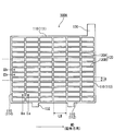
- FIG. 1A and 1B are plan views showing the appearance of current collectors 100A and 100B according to one embodiment and another embodiment of the present invention, respectively.
- Each of the current collectors 100A and 100B has a frame bone 110 and a mesh-like inner bone 120 inside the frame bone 110.
- the frame bone 110 includes an ear 130, an upper element 111 continuous with the ear 130, a lower element 112 facing the upper element 111, and a pair of side elements 113 and 114 connecting the upper element 111 and the lower element 112. Equipped with.
- the dashed line indicates the boundary that divides the internal bone into three equal parts: the upper region, the middle region, and the lower region.
- the transverse bone extends obliquely with respect to the upper element or the lower element.
- LH indicates the internal length per lattice of the vertical bone
- LW indicates the internal length per lattice of the lateral bone.
- the current collectors 100A and 100B are, for example, punched lattices of a lead or lead alloy stretched sheet, and the stretching direction is the direction indicated by the arrow MD in FIG.
- the cross section C of the vertical bone 120A is a cross section taken along the line IIa-IIa in FIG. 1
- the cross section G of the lateral bone 120B is a cross section taken along the line IIb-IIb.
- the metal structure of the stretched sheet tends to form a layered or fibrous structure extending in the stretching direction. Therefore, a striped pattern is formed on the cross section C.
- the cross section G may have a pattern formed by cutting a layered or fibrous structure.
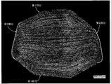
- FIG. 2A is an example of a photograph of the cross section C of the vertical bone 120A, and the cross section has an octagonal shape, and a striped pattern of metal fibrous tissue can be seen.
- FIG. 2B is a conceptual diagram of an example of an octagonal cross section C imitating FIG. 2A.
- FIG. 3 is an example of a photograph of the cross section G of the transverse bone 120B, and a pattern of the cross section perpendicular to the fiber length of the fibrous structure of the metal can be seen in the cross section.
- most of the left and right sides of the octagonal cross section C are the second portion 220, and the other outer peripheral region is the first portion 210.
- FIG. 4 is a conceptual diagram of a cross section C showing the progress of corrosion of the internal bone.
- the portion where the shallow corrosive layer is formed is the first portion where the fibrous structure extends along the contour of the cross section C, and it is difficult for the corrosive layer to be formed deeply even if the corrosion progresses. Therefore, peeling tends to occur near the interface between the current collector and the electrode material. Therefore, it is considered that the stress that the current collector tries to deform is easily relaxed.
- the portion where the wedge-shaped deep corrosive layer is formed is the second portion. When a deep corrosive layer is formed, non-uniform deformation of the current collector is likely to occur, the current collector is stretched, and the electrode material is likely to fall off.
- the positive electrode plate for a lead storage battery includes the above-mentioned current collector and a positive electrode material held by the current collector (positive electrode current collector).
- As the positive electrode plate what is called a paste type positive electrode plate is used.
- the positive electrode material is obtained by removing the positive electrode current collector from the positive electrode plate.
- a member such as a mat or pacing paper may be attached to the positive electrode plate. Since such a member (pasting member) is used integrally with the positive electrode plate, it is included in the positive electrode plate.
- the positive electrode plate includes such a member, the positive electrode material is the one excluding the positive electrode current collector and the sticking member. However, when a sticking member such as a mat is stuck to the separator, the thickness of the sticking member is included in the thickness of the separator.
- the positive electrode current collector is preferably a punched current collector.
- the current collector has a frame bone and an internal bone inside the frame bone.
- a grid-shaped current collector (positive electrode grid) is preferable.
- the inner bone portion has a lattice shape (including a mesh shape). By using the positive electrode lattice, it becomes easy to support the positive electrode material.
- the frame bone is preferably rectangular. The rectangle does not have to be a strict rectangle, and the vertices may be slightly rounded or each side may be slightly bent.
- the positive electrode current collector can be formed by press punching a lead or lead alloy sheet.
- the sheet is preferably a stretched sheet (also referred to as a rolled plate) that has been stretched.
- the stretched sheet may be a uniaxially stretched sheet or a biaxially stretched sheet.
- the lead alloy used for the positive electrode current collector a Pb—Sb alloy, a Pb—Ca alloy, a Pb—Ca—Sn alloy, or a Pb—Sn alloy is preferable in terms of corrosion resistance and mechanical strength. Further, lead having a purity equal to or higher than that of three nines (purity of 99.9% by mass or higher) may be used for the positive electrode current collector.
- the positive electrode current collector may include a surface layer. It may have lead alloy layers (surface layers) having different compositions, and may have a plurality of alloy layers. The composition of the surface layer and the inner layer of the positive electrode current collector may be different. The surface layer may be formed on a part of the positive electrode current collector. The surface layer may be formed only on the lattice portion of the positive electrode current collector or only on the frame bone portion (only the ear portion, only the frame bone portion other than the ear, etc.).
- the positive electrode material contains a positive electrode active material (lead dioxide or lead sulfate) whose capacity is developed by a redox reaction.
- the positive electrode material may contain additives, if necessary.
- the unchemical paste type positive electrode plate is obtained by filling the positive electrode current collector with the positive electrode paste, aging and drying.
- the positive electrode paste is prepared by kneading lead powder, additives, water, and sulfuric acid. Then, a positive electrode plate is obtained by forming these unchemicald positive electrode plates.
- the chemical conversion can be carried out by charging the electrode plate group in a state where the electrode plate group including the unchemical positive electrode plate is immersed in the electrolytic solution containing sulfuric acid in the electric tank of the lead storage battery. However, chemical conversion may be performed before assembling the lead-acid battery or the electrode plate group.
- the negative electrode plate of a lead storage battery is composed of a current collector and a negative electrode material.
- the negative electrode electrode material is a negative electrode plate obtained by removing the negative electrode current collector.
- a member such as a mat or pacing paper may be attached to the negative electrode plate. Since such a member (pasting member) is used integrally with the negative electrode plate, it is included in the negative electrode plate.
- the negative electrode material is the one excluding the negative electrode current collector and the sticking member.
- the negative electrode current collector may be formed by casting lead (Pb) or a lead alloy, or may be formed by processing a sheet of lead or a lead alloy. Examples of the processing method include expanding processing and punching processing. It is preferable to use a grid-shaped current collector (negative electrode lattice) as the negative electrode current collector because it is easy to support the negative electrode material. As the negative electrode current collector, a current collector as described for the positive electrode current collector may be used.
- the lead alloy used for the negative electrode current collector may be any of Pb-Sb-based alloys, Pb-Ca-based alloys, and Pb-Ca-Sn-based alloys. These leads or lead alloys may further contain, as an additive element, at least one selected from the group consisting of Ba, Ag, Al, Bi, As, Se, Cu and the like.
- the negative electrode current collector may include a surface layer. The surface layer and the inner layer of the negative electrode current collector may have different compositions. The surface layer may be formed on a part of the negative electrode current collector. The surface layer may be formed on the ears of the negative electrode current collector. The surface layer of the ear may contain Sn or a Sn alloy.
- the negative electrode material contains a negative electrode active material (lead or lead sulfate) whose capacity is developed by a redox reaction as an essential component, and may contain additives (organic shrink-proofing agent, carbonaceous material, barium sulfate, etc.).
- the negative electrode active material in the charged state is spongy lead, but the unchemicald negative electrode plate is usually produced using lead powder.
- lignins include lignin and lignin derivatives.
- lignin derivative include lignin sulfonic acid or a salt thereof (alkali metal salt (sodium salt, etc.), etc.).
- the synthetic organic shrinkage proofing agent is an organic polymer containing a sulfur element, and generally contains a plurality of aromatic rings in the molecule and also contains a sulfur element as a sulfur-containing group.
- a sulfonic acid group or a sulfonyl group in a stable form is preferable.
- the sulfonic acid group may be present in the acid form or in the salt form such as the Na salt.
- a condensate made of an aldehyde compound (aldehyde or a condensate thereof, for example, formaldehyde) of a compound having a sulfur-containing group and an aromatic ring is preferable.
- the aromatic ring include a benzene ring and a naphthalene ring.
- the plurality of aromatic rings may be directly bonded or linked by a linking group (for example, an alkylene group, a sulfone group, etc.). Examples of such a structure include biphenyl, bisphenyl alkane, bisphenyl sulfone and the like.
- Examples of the compound having an aromatic ring include the above-mentioned compound having an aromatic ring and a hydroxy group and / or an amino group.
- the hydroxy group or amino group may be directly bonded to the aromatic ring, or may be bonded as an alkyl chain having a hydroxy group or amino group.
- a bisphenol compound, a hydroxybiphenyl compound, a hydroxynaphthalene compound, a phenol compound and the like are preferable.
- the compound having an aromatic ring may further have a substituent.
- the organic shrinkage proofing agent may contain one type of residues of these compounds, or may contain a plurality of types.
- bisphenol compound bisphenol A, bisphenol S, bisphenol F and the like are preferable.
- the sulfur-containing group may be directly bonded to the aromatic ring contained in the compound, or may be bonded to the aromatic ring as an alkyl chain having a sulfur-containing group, for example.
- a condensate of the above compound having an aromatic ring and a monocyclic aromatic compound (aminobenzene sulfonic acid, alkylaminobenzene sulfonic acid, phenol sulfonic acid or a substitute thereof, etc.) with an aldehyde compound can be obtained.
- a condensate of the above compound having an aromatic ring and a monocyclic aromatic compound (aminobenzene sulfonic acid, alkylaminobenzene sulfonic acid, phenol sulfonic acid or a substitute thereof, etc.) with an aldehyde compound.
- an aldehyde compound May be used as an organic shrinkage proofing agent.
- the content of the organic shrink-proofing agent contained in the negative electrode electrode material is, for example, 0.01% by mass or more, and may be 0.02% by mass or more or 0.05% by mass or more.
- the content of the organic shrink-proofing agent is, for example, 1.0% by mass or less, and may be 0.8% by mass or less or 0.5% by mass or less.
- carbon black As the carbonaceous material contained in the negative electrode material, carbon black, graphite, hard carbon, soft carbon and the like can be used.
- carbon black examples include acetylene black, furnace black, and lamp black.
- Furness Black also includes Ketjen Black (trade name).
- the graphite may be any carbon material containing a graphite-type crystal structure, and may be either artificial graphite or natural graphite.
- the content of the carbonaceous material in the negative electrode material is, for example, 0.05% by mass or more, and may be 0.2% by mass or more.
- the content of the carbonaceous material is, for example, 4.0% by mass or less, and may be 3% by mass or less or 2% by mass or less.
- the content of barium sulfate in the negative electrode electrode material is, for example, 0.5% by mass or more, and may be 1% by mass or more or 1.3% by mass or more.
- the content of barium sulfate is, for example, 3.0% by mass or less, and may be 2.5% by mass or less or 2% by mass or less.
- the method for quantifying the organic shrinkage-proofing agent, carbonaceous material, and barium sulfate contained in the negative electrode material will be described below.
- the lead-acid battery after chemical conversion is fully charged and then disassembled to obtain the negative electrode plate to be analyzed.
- the obtained negative electrode plate is washed with water to remove sulfuric acid from the negative electrode plate. Washing with water is performed by pressing the pH test paper against the surface of the negative electrode plate washed with water until it is confirmed that the color of the test paper does not change. However, the time for washing with water shall be within 2 hours.
- the negative electrode plate washed with water is dried at 60 ⁇ 5 ° C. for about 6 hours in a reduced pressure environment.
- sample A a sample (hereinafter referred to as sample A) is obtained by separating the negative electrode material from the negative electrode plate. Sample A is pulverized as needed.
- the pulverized sample A is immersed in a 1 mol / L NaOH aqueous solution to extract an organic shrinkage proofing agent.
- the insoluble components are removed by filtration from the extracted NaOH aqueous solution containing the organic shrinkage proofing agent.
- the obtained filtrate (hereinafter, also referred to as filtrate B) is desalted, concentrated, and dried to obtain a powder of an organic shrink-proofing agent (hereinafter, also referred to as sample C).
- Desalination is carried out using a desalting column, by passing the filtrate B through an ion exchange membrane, or by placing the filtrate B in a dialysis tube and immersing it in distilled water.
- the organic shrink-proofing agent is specified by combining the information obtained from the thermal decomposition GC-MS or the like, which can obtain the information of the individual compounds.
- the content of the organic shrink-proofing agent in the negative electrode material is quantified using the spectral intensity and the calibration curve prepared in advance. If the structural formula of the organic shrink-proofing agent to be analyzed cannot be specified exactly and the calibration curve of the same organic shrinkage-proofing agent cannot be used, the ultraviolet-visible absorption spectrum and infrared spectroscopic spectrum similar to those of the organic shrinkage-proofing agent to be analyzed, A calibration curve is prepared using an available organic shrink-proofing agent showing an NMR spectrum or the like.
- a carbonaceous material and components other than barium sulfate are removed from the dispersion liquid using a sieve.
- the dispersion is suction-filtered using a membrane filter whose mass has been measured in advance, and the membrane filter is dried together with the filtered sample in a dryer at 110 ° C. ⁇ 5 ° C.
- the obtained sample is a mixed sample of a carbonaceous material and barium sulfate (hereinafter, also referred to as sample D).
- sample D a mixed sample of a carbonaceous material and barium sulfate
- the dried sample D is put into a crucible together with a membrane filter and incinerated at 700 ° C. or higher.
- the remaining residue is barium oxide.
- the mass of the barium oxide is converted to the mass of the barium sulfate determining the mass of barium sulfate (M B). Calculating the mass of the carbonaceous material from the mass M m by subtracting the mass M B.
- the negative electrode plate can be formed by filling a negative electrode current collector with a negative electrode paste, aging and drying to prepare an unchemicald negative electrode plate, and then forming an unchemicald negative electrode plate.
- the negative electrode paste is prepared by adding water and sulfuric acid to lead powder and various additives and kneading them. In the aging step, it is preferable to ripen the unchemicald negative electrode plate at room temperature or at a higher temperature and high humidity.
- Chemical formation can be performed by charging the electrode plate group in a state where the electrode plate group including the unchemical negative electrode plate is immersed in the electrolytic solution containing sulfuric acid in the cell of the lead storage battery. However, chemical conversion may be performed before assembling the lead-acid battery or the electrode plate group. The chemical formation produces spongy lead.
- a separator is usually arranged between the negative electrode plate and the positive electrode plate.
- a non-woven fabric, a microporous membrane, or the like is used as the separator.
- the thickness of the separator interposed between the negative electrode plate and the positive electrode plate may be selected according to the distance between the electrodes.
- the number of separators may be selected according to the number of poles.
- Nonwoven fabric is a mat that is entwined without weaving fibers, and is mainly composed of fibers.
- the non-woven fabric for example, 60% by mass or more of the non-woven fabric is formed of fibers.
- the fiber glass fiber, polymer fiber (polyolefin fiber, acrylic fiber, polyester fiber (polyethylene terephthalate fiber, etc.), etc.), pulp fiber, and the like can be used. Of these, glass fiber is preferable.
- the non-woven fabric may contain components other than fibers, for example, an acid-resistant inorganic powder and a polymer as a binder.
- the microporous film is a porous sheet mainly composed of components other than fiber components.
- a composition containing a pore-forming agent at least one of a polymer powder and an oil
- the microporous membrane is preferably composed of a material having acid resistance, and preferably contains a polymer component as a main component.
- polymer component polyolefin (polyethylene, polypropylene, etc.) is preferable.
- the separator may be composed of, for example, only a non-woven fabric or only a microporous membrane. Further, the separator may be a laminate of a non-woven fabric and a microporous film, a material obtained by laminating different or similar materials, or a material in which irregularities are engaged with different or similar materials, as required.
- the separator may be in the shape of a sheet or in the shape of a bag.
- a single sheet-shaped separator may be sandwiched between the positive electrode plate and the negative electrode plate.
- the electrode plate may be arranged so as to be sandwiched between a single sheet-shaped separator in a bent state.
- the positive electrode plate sandwiched between the bent sheet-shaped separators and the negative electrode plate sandwiched between the bent sheet-shaped separators may be overlapped, and one of the positive electrode plate and the negative electrode plate may be sandwiched between the bent sheet-shaped separators. , May be overlapped with the other electrode plate.
- the sheet-shaped separator may be bent in a bellows shape, and the positive electrode plate and the negative electrode plate may be sandwiched between the bellows-shaped separators so that the separator is interposed between them.
- the separator may be arranged so that the bent portion is along the horizontal direction of the lead storage battery (for example, the bent portion is parallel to the horizontal direction), and is along the vertical direction. (For example, the separator may be arranged so that the bent portion is parallel to the vertical direction).
- recesses are alternately formed on both main surface sides of the separator.
- the positive electrode plate is formed only in the concave portion on one main surface side of the separator.
- a negative electrode plate is arranged (that is, a double separator is interposed between the adjacent positive electrode plate and the negative electrode plate).
- the separator is arranged so that the bent portion is along the vertical direction of the lead-acid battery, the positive electrode plate can be accommodated in the recess on one main surface side and the negative electrode plate can be accommodated in the recess on the other main surface side (that is,).
- a separator may be provided in a single layer between the adjacent positive electrode plate and the negative electrode plate.)
- the bag-shaped separator may accommodate a positive electrode plate or a negative electrode plate.
- the vertical direction is defined with the side on which the ear is provided as the upper side and the side opposite to the ear as the lower side.
- the vertical direction of the electrode plate may be the same as or different from the vertical direction of the lead storage battery. That is, the lead-acid battery may be installed vertically or horizontally.
- the electrolytic solution is an aqueous solution containing sulfuric acid, and may be gelled if necessary.
- the electrolyte may optionally include cations (eg, metal cations (such as at least one selected from sodium, lithium, magnesium, and aluminum ions) and anions (eg, anions other than sulfate anions (phosphoric acid)). Ions, etc.)) may be included.
- the specific gravity of the electrolytic solution in a fully charged lead-acid battery at 20 ° C. is, for example, 1.20 or more, and may be 1.25 or more.
- the specific gravity of the electrolytic solution in a fully charged lead-acid battery at 20 ° C. is, for example, 1.35 or less, and may be 1.32 or less.
- a lead-acid battery including the positive electrode plate including the current collector is manufactured by a manufacturing method including, for example, a step of preparing the current collector and a step of obtaining a positive electrode plate containing the current collector and the positive electrode material. Can be manufactured.
- the current collector is prepared by the above-mentioned method for manufacturing a current collector. More specifically, the current collector is prepared by, for example, a manufacturing method including the steps (i) to (iv) described above.
- the positive electrode plate can be manufactured by the procedure described in the section of the positive electrode plate.
- the lead-acid battery can be obtained by a manufacturing method including a step of assembling the lead-acid battery by accommodating the positive electrode plate, the negative electrode plate and the electrolytic solution obtained above in an electric tank.
- the separator is usually arranged so as to be interposed between the positive electrode plate and the negative electrode plate.
- the step of assembling the lead-acid battery may include, if necessary, a step of forming at least one of the positive electrode plate and the negative electrode plate after the step of accommodating the positive electrode plate, the negative electrode plate, and the electrolytic solution in the battery case.
- the negative electrode plate, the electrolytic solution, and the separator are each prepared before being housed in the battery case.
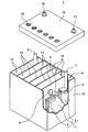
- FIG. 5 shows the appearance of an example of the lead storage battery according to the embodiment of the present invention.
- the lead-acid battery 1 includes an electric tank 12 that houses a electrode plate group 11 and an electrolytic solution (not shown).
- the inside of the electric tank 12 is partitioned into a plurality of cell chambers 14 by a partition wall 13. In each cell chamber 14, one electrode plate group 11 is stored.
- the opening of the battery case 12 is closed by a lid 15 including a negative electrode terminal 16 and a positive electrode terminal 17.
- the lid 15 is provided with a liquid spout 18 for each cell chamber. At the time of refilling water, the liquid spout 18 is removed and the refilling liquid is replenished.
- the liquid spout 18 may have a function of discharging the gas generated in the cell chamber 14 to the outside of the battery.
- the electrode plate group 11 is formed by laminating a plurality of negative electrode plates 2 and positive electrode plates 3 via a separator 4, respectively.
- the bag-shaped separator 4 accommodating the negative electrode plate 2 is shown, but the form of the separator is not particularly limited.
- the negative electrode shelf portion 6 for connecting the plurality of negative electrode plates 2 in parallel is connected to the through connecting body 8, and the positive electrode shelf portion for connecting the plurality of positive electrode plates 3 in parallel. 5 is connected to the positive electrode column 7.
- the positive electrode column 7 is connected to the positive electrode terminal 17 outside the lid 15.
- the negative electrode column 9 is connected to the negative electrode shelf 6, and the through connector 8 is connected to the positive electrode shelf 5.
- the negative electrode column 9 is connected to the negative electrode terminal 16 outside the lid 15.
- Each through-connecting body 8 passes through a through-hole provided in the partition wall 13 and connects the electrode plates 11 of the adjacent cell chambers 14 in series.
- the positive electrode shelf 5 is formed by welding the ears provided on the upper part of each positive electrode plate 3 by a cast-on strap method or a burning method.
- the negative electrode shelf portion 6 is also formed by welding the ears provided on the upper portions of the negative electrode plates 2 as in the case of the positive electrode shelf portion 5.
- the lid 15 of the lead storage battery has a single structure (single lid), but is not limited to the case shown in the illustrated example.
- the lid 15 may have, for example, a double structure including an inner lid and an outer lid (or upper lid).
- the lid having a double structure is provided with a reflux structure between the inner lid and the outer lid for returning the electrolytic solution to the inside of the battery (inside the inner lid) from the reflux port provided on the inner lid. May be good.
- FIG. 5 shows an example of a liquid battery (vent type battery)
- the lead storage battery may be a control valve type battery (VRLA type).
- VRLA type control valve type battery
- test battery (A) First single plate overcharge test Using a predetermined test battery, an overcharge test with a constant current of 1.7 A (current density: 0.0054 A / cm 2 ) was performed for 5 days in a water tank at 75 ° C ⁇ 2 ° C. After that, the operation of resting for 2 days (1 week) is repeated for 3 weeks.
- the apparent current collector area when calculating the current density is twice the product of the height and width of the outer frame of the positive electrode current collector.
- the following evaluation (a) or (b) is performed on the positive electrode current collector taken out from the fully charged test battery.
- the positive electrode current collector used for the evaluation is prepared by being taken out from the test battery, washed with water, dried, and the electrode material is removed, as in the case of the current collector when forming the cross section C.
- Corrosion rate (%) ⁇ (mass of positive electrode current collector before overcharge test-mass of positive electrode current collector with corrosive layer removed by mannitting after overcharge test) ⁇ (positive electrode current collector before overcharge test) Body mass) ⁇ x 100
- Width elongation and height elongation of the positive electrode current collector Measure the dimensions of the most bulging portion of the frame bone of the positive electrode current collector in the first direction (height direction) and the second direction (width direction), respectively. , Find the width elongation and height elongation compared to the initial dimensions.
- the dimensions of the most bulging part of the frame bone in the second direction (width direction) of the positive electrode current collector taken out from the fully charged test battery were measured and compared with the initial dimensions. To find the amount of width elongation.
- the positive electrode current collector used for the evaluation is prepared by being taken out from the test battery, washed with water, dried, and the electrode material is removed, as in the case of the current collector when forming the cross section C.
- Lead-acid batteries A11 to A13, B11 to B13, and B21 to B26 >> (1) Preparation of lead-acid battery (a) Preparation of current collector The rolled sheet of Pb-Ca—Sn alloy is punched, the inner bone is pressed, and the current collectors a11 to a13 and b11 to shown in Table 1 are pressed. b13 and b21 to b26 are obtained, respectively. At this time, the ratio R1 is adjusted by adjusting the press speed and the press pressure. The ratio W1 / W2 is adjusted by adjusting the ratio of the portion removed by punching and the remaining portion when punching the rolled sheet.
- the thickness of the internal bone is 0.95 mm
- the width of the frame bone is 1.0 mm
- the WLH / WLW is 1.37.
- the WLH / WLW of the current collectors a11 and a13 are both 1.3 or more.
- test battery X A lead-acid battery (test battery X: rated voltage 2V, rated 5-hour rate capacity 6Ah) is assembled using an unchemical positive electrode plate containing a positive electrode current collector and a positive electrode material.
- the test battery X is composed of one unchemical positive electrode plate and two unchemical negative electrode plates sandwiching the positive electrode plate, and is chemically formed in an electrolytic solution.
- the negative electrode plate is housed in a bag-shaped separator.
- An aqueous sulfuric acid solution is used as the electrolytic solution. After chemical conversion, the specific gravity of the electrolytic solution at 20 ° C. is adjusted to 1.28 in the fully charged test battery.
- Lead-acid batteries A31 to A33 and B31 >> (1) Preparation of lead-acid battery
- the current collectors a31 to a33 and b31 shown in Table 2 are manufactured.
- the ratio R1 and the ratio W1 / W2 are adjusted in the same manner as in the case of the lead storage battery A11.
- a lead storage battery (test battery Y) is assembled using the obtained current collector without supporting the positive electrode material.
- As the electrolytic solution an aqueous sulfuric acid solution having a specific gravity of 1.28 at 20 ° C. is used.
- the test battery Y is assembled in the same manner as in the case of the lead storage battery A11.
- the test battery Y is composed of one positive electrode current collector, two ready-made negative electrode plates sandwiching the positive electrode current collector, and an electrolytic solution.
- the negative electrode plate is housed in a bag-shaped separator.
- FIG. 7 shows the relationship between the ratio R1, the corrosion rate, and the amount of deformation (width elongation, height elongation of the current collector) with respect to the current collectors a31 to a33 and b31.
- the corrosion rate does not change so much, the height elongation is suppressed when the ratio R1 is 50% or more, and the height elongation and width are suppressed when the ratio R1 is 60% or more. Both elongation are greatly suppressed.
- the ratio R1 may be 75% or more or 80% or more.
- Lead-acid batteries A41-A47 (1) Preparation of lead-acid battery
- the current collectors a41 to a47 shown in Table 3 are manufactured.
- the ratio R1 and the ratio W1 / W2 are adjusted in the same manner as in the case of the lead storage battery A11.
- the obtained current collector is used as a positive electrode current collector and a negative electrode current collector to produce an unchemicald positive electrode plate and a negative electrode plate in the same manner as in the case of the lead storage battery A11.
- a lead storage battery (test battery Z) is assembled using the obtained unchemical positive electrode plate and negative electrode plate.
- the unchemical negative electrode plate is housed in a bag-shaped separator, and an electrode group is formed by eight unchemical negative electrode plates and eight unchemical positive electrode plates.
- a group of electrode plates is housed in a polypropylene electric tank together with an electrolytic solution, and chemical conversion is performed in the electric tank to prepare a test battery Z (12 V, rated 5-hour rate capacity 48 Ah).
- An aqueous sulfuric acid solution is used as the electrolytic solution.
- the specific gravity of the electrolytic solution at 20 ° C. is adjusted to 1.28 in the fully charged test battery.
- Lead-acid batteries A51 to A54 and B51 to B54 >> (1) Preparation of lead-acid battery The current collectors a51 to a54 and b51 to b54 shown in Table 4 are prepared. The ratio R1 and the ratio W1 / W2 are adjusted in the same manner as in the case of the lead storage battery A11. The ratio WLH / WLW is adjusted by adjusting the press speed and press pressure. The obtained current collectors are used as the positive electrode current collector and the negative electrode current collector to prepare lead-acid batteries A51 to A54 and B51 to B54 (test battery X) in the same manner as in the case of the lead-acid battery A11.
- the lead-acid battery current collector according to the present invention is applicable to control valve type and liquid type lead-acid batteries.
- a lead-acid battery provided with an electrode plate including a current collector can be suitably used as a power source for starting a vehicle (automobile, motorcycle, etc.) and a power source for an industrial power storage device (electric vehicle (forklift, etc.)). It should be noted that these uses are merely examples and are not limited to these uses.
- Negative electrode plate 3 Positive electrode plate 4: Separator 5: Positive electrode shelf part 6: Negative electrode shelf part 7: Positive electrode pillar 8: Through connector 9: Negative electrode pillar 11: Electrode plate group 12: Electric tank 13: Partition 14: Cell chamber 15: Lid 16: Negative electrode terminal 17: Positive electrode terminal 18: Liquid port plug 100A, 100B: Current collector 110: Frame bone 111: Upper element 112: Lower element 113, 114: Side element 120: Inner bone 120A, B1: Vertical bone 120B: Horizontal bone 130: Ear 132: Lower electrode (foot) 210: First part of the longitudinal bone 220: Second part of the longitudinal bone
Abstract
A current collector for a lead storage battery, according to the present invention, comprises a frame skeleton and an inner skeleton inside the frame. The frame skeleton is equipped with an ear, an upper element connecting to the ear, a lower element facing the upper element, and a pair of side elements connecting the upper element and the lower element. The inner skeleton is equipped with a vertical skeleton extending in a first direction from the upper element toward the lower element, and a horizontal skeleton extending in a second direction from one of the side elements toward the other side element. A striped pattern of a metal fibrous structure is seen in a cross section perpendicular to the first direction of the vertical skeleton, and an outer peripheral region of the cross section is formed of a first portion in which the fibrous structure extends along the contour of the cross section and a second portion other than the first portion. The ratio of the length of the contour corresponding to the first portion to the entire length of the contour of the cross section is 50% or more, and the ratio W1/W2 of the mass W1 of the frame skeleton to the mass W2 of the inner skeleton satisfies the equation 0.2 ≤ W1/W2 ≤ 0.42.
Description
本発明は、鉛蓄電池用集電体、鉛蓄電池用正極板、および鉛蓄電池に関する。
The present invention relates to a current collector for a lead storage battery, a positive electrode plate for a lead storage battery, and a lead storage battery.
鉛蓄電池は、車載用、産業用の他、様々な用途で使用されている。鉛蓄電池は、正極板と負極板とが交互にセパレータを介して積層された極板群を具備する。電極板は、集電体と、集電体に保持された電極材料とで構成されている。
Lead-acid batteries are used for various purposes such as in-vehicle use and industrial use. The lead-acid battery includes a group of electrode plates in which positive electrode plates and negative electrode plates are alternately laminated via separators. The electrode plate is composed of a current collector and an electrode material held by the current collector.
特許文献1は、鉛合金の圧延板をプレス打ち抜きしてなる鉛格子板において、内部の縦および横の桟の厚さを外枠の厚さよりも薄くし、かつ外枠の厚さが0.8~1.5mm、内部の桟の厚さが0.6~0.8mmの範囲にあることを特徴とする鉛蓄電池用鉛格子板を提案している。また、引用文献1は、厚さ1.2~1.5mmの鉛合金の圧延板をプレス打ち抜きして得られる鉛格子板の内部枠に対して厚さ方向に変形を加えて内部の縦及び横の桟の厚さを0.6~0.8mmの範囲に設定したことを特徴とする鉛蓄電池用鉛格子板を提案している。
In Patent Document 1, in a lead lattice plate obtained by press-punching a rolled plate of a lead alloy, the thickness of the inner vertical and horizontal crosspieces is made thinner than the thickness of the outer frame, and the thickness of the outer frame is 0. We have proposed a lead grid plate for lead storage batteries, which is characterized in that the thickness of the crosspiece is in the range of 8 to 1.5 mm and the thickness of the internal crosspiece is in the range of 0.6 to 0.8 mm. Further, in Cited Document 1, the inner frame of a lead lattice plate obtained by pressing and punching a rolled plate of a lead alloy having a thickness of 1.2 to 1.5 mm is deformed in the thickness direction to form the inner length and the inside. We are proposing a lead grid plate for lead storage batteries, which is characterized in that the thickness of the horizontal crosspiece is set in the range of 0.6 to 0.8 mm.
特許文献2は、枠骨と、この枠骨の外側に配置される耳と、前記枠骨の内側に配置され、格子を形成する内骨とを備え、前記枠骨と耳との加算質量(枠骨+耳)が、内骨の質量よりも軽い正極格子基板を提案している。
Patent Document 2 includes a frame bone, an ear arranged outside the frame bone, and an internal bone arranged inside the frame bone and forming a lattice, and the additional mass of the frame bone and the ear ( The frame bone + ear) proposes a positive lattice substrate that is lighter than the mass of the internal bone.
特許文献3は、枠骨と、複数の横桟と複数の縦桟とからなる内骨とを有する鉛蓄電池用格子体において、前記複数の縦桟の上端部は、それぞれ前記枠骨の上部横骨に連結され且つ前記複数の縦桟は相互の交差しないようにして前記枠骨の下部横骨側に向かって延びており、前記枠骨の上部横骨の質量を格子体全体の質量の11%以上14%以下とし、前記上部横骨の質量と前記複数の縦桟の質量とを合わせた質量が格子体全体の質量の60%以上70%以下となるように質量を配分したことを特徴とする鉛蓄電池用格子体を提案している。
Patent Document 3 describes a lead storage battery lattice body having a frame bone and an inner bone composed of a plurality of horizontal rails and a plurality of vertical rails, and the upper end portions of the plurality of vertical rails are each on the upper side of the frame bone. The plurality of vertical crosspieces are connected to the bone and extend toward the lower transverse bone side of the frame bone so as not to intersect with each other, and the mass of the upper transverse bone of the frame bone is 11 of the mass of the entire lattice. % Or more and 14% or less, and the mass is distributed so that the total mass of the upper lateral bone and the mass of the plurality of vertical crosspieces is 60% or more and 70% or less of the total mass of the lattice body. We are proposing a grid for lead storage batteries.
特許文献1および2では、格子状集電体の厚みまたは質量のバランスを調節することで、電極材料の保持力がある程度向上すると考えられる。特許文献3では、格子状集電体の電圧特性を制御することで、集電性の低下または電極材料の劣化をある程度抑制できると考えられる。しかし、高温過充電試験を行うと、格子状集電体の伸びまたは湾曲が顕著になり、電極材料が脱落して寿命性能が低下する場合がある。
In Patent Documents 1 and 2, it is considered that the holding power of the electrode material is improved to some extent by adjusting the thickness or mass balance of the lattice-shaped current collector. In Patent Document 3, it is considered that the deterioration of the current collecting property or the deterioration of the electrode material can be suppressed to some extent by controlling the voltage characteristics of the lattice-shaped current collector. However, when the high-temperature overcharge test is performed, the lattice-shaped current collector may be significantly stretched or curved, and the electrode material may fall off, resulting in a decrease in life performance.
本発明の一側面は、鉛蓄電池用集電体であって、
枠骨と、前記枠骨の内側の内骨と、を有し、
前記枠骨は、耳と、前記耳と連続する上部要素と、前記上部要素と対向する下部要素と、前記上部要素と前記下部要素とを連結する一対の側部要素と、を具備し、
前記内骨は、前記上部要素から前記下部要素に向かう第1方向に延びる縦骨と、一方の前記側部要素から他方の前記側部要素に向かう第2方向に延びる横骨と、を具備し、
前記縦骨の前記第1方向に垂直な断面において、金属の繊維状組織の縞模様が見られ、
前記断面の外周領域は、前記繊維状組織が前記断面の輪郭に沿って延びる第1部分と、前記第1部分以外の第2部分と、で構成され、
前記断面の輪郭の全長に占める前記第1部分に対応する輪郭の長さの割合:R1は、50%以上であり、
前記枠骨の質量W1の前記内骨の質量W2に対する比:W1/W2は、
0.2≦W1/W2≦0.42
を充足する、鉛蓄電池用集電体に関する。 One aspect of the present invention is a current collector for a lead storage battery.
It has a frame bone and an inner bone inside the frame bone.
The frame bone comprises an ear, an upper element continuous with the ear, a lower element facing the upper element, and a pair of side elements connecting the upper element and the lower element.
The internal bone comprises a longitudinal bone extending from the upper element toward the lower element in a first direction and a transverse bone extending from one side element toward the other side element in a second direction. ,
In the cross section of the longitudinal bone perpendicular to the first direction, a striped pattern of metallic fibrous tissue is seen.
The outer peripheral region of the cross section is composed of a first portion in which the fibrous structure extends along the contour of the cross section and a second portion other than the first portion.
The ratio of the length of the contour corresponding to the first portion to the total length of the contour of the cross section: R1 is 50% or more.
The ratio of the mass W1 of the frame bone to the mass W2 of the inner bone: W1 / W2 is
0.2 ≤ W1 / W2 ≤ 0.42
Regarding the current collector for lead-acid batteries, which satisfies the above.
本発明の一側面に係る鉛蓄電池用集電体は、枠骨と、枠骨の内側の内骨と、を有する。枠骨は、耳と、耳と連続する上部要素と、上部要素と対向する下部要素と、上部要素と下部要素とを連結する一対の側部要素と、を具備する。内骨は、上部要素から下部要素に向かう第1方向に延びる縦骨と、一方の側部要素から他方の側部要素に向かう第2方向に延びる横骨と、を具備する。縦骨の第1方向に垂直な断面においては、金属の繊維状組織の縞模様が見られる。断面の外周領域は、繊維状組織が前記断面の輪郭に沿って延びる第1部分と、第1部分以外の第2部分と、で構成される。断面の輪郭の全長に占める第1部分に対応する輪郭の長さの割合:R1は、50%以上である。枠骨の質量W1の内骨の質量W2に対する比:W1/W2は、0.2≦W1/W2≦0.42を充足する。
The lead-acid battery current collector according to one aspect of the present invention has a frame bone and an inner bone inside the frame bone. The frame bone comprises an ear, an upper element continuous with the ear, a lower element facing the upper element, and a pair of side elements connecting the upper element and the lower element. The internal bone comprises a longitudinal bone extending in the first direction from the upper element to the lower element and a transverse bone extending in the second direction from one side element to the other side element. In the cross section perpendicular to the first direction of the longitudinal bone, a striped pattern of metal fibrous tissue can be seen. The outer peripheral region of the cross section is composed of a first portion in which the fibrous structure extends along the contour of the cross section and a second portion other than the first portion. The ratio of the length of the contour corresponding to the first portion to the total length of the contour of the cross section: R1 is 50% or more. The ratio of the mass W1 of the frame bone to the mass W2 of the inner bone: W1 / W2 satisfies 0.2 ≦ W1 / W2 ≦ 0.42.
なお、集電体は、格子体とも称する。ただし、集電体もしくは格子体の骨格は、格子状もしくは網目状に限定されるものではない。
The current collector is also called a grid. However, the skeleton of the current collector or the grid is not limited to the grid or the mesh.
枠骨(より具体的には、枠骨の耳部を除く部分)は、通常、概ね四角形であり、矩形であってもよい。四角形は、上部要素と一対の側部要素とがそれぞれ成す角度、および下部要素と一対の側部要素とがそれぞれ成す角度(合計4つの角度)のうち、少なくとも1つが90℃ではない四角形(例えば台形)であってもよい。四角形の四隅のうち、少なくとも1つは、面取りされていてもよい。面取りは、C面取りでもR面取りでもよい。通常は、隅部を丸めるR面取りが好ましい。
The frame bone (more specifically, the portion of the frame bone excluding the ear portion) is usually generally rectangular, and may be rectangular. A quadrangle is a quadrangle in which at least one of the angles formed by the upper element and the pair of side elements and the angles formed by the lower element and the pair of side elements (a total of four angles) is not 90 ° C. It may be trapezoidal). At least one of the four corners of the quadrangle may be chamfered. The chamfer may be C chamfer or R chamfer. Usually, R chamfering with rounded corners is preferable.
枠骨が矩形の場合、第1方向は、側部要素に平行な方向であり、第2方向は、上部要素および下部要素に平行な方向である。枠体が矩形以外の四角形であり、液式の鉛蓄電池の場合、通常の鉛蓄電池の使用状態において、第1方向は、鉛直方向に対応し、第2方向は、水平方向に対応する。枠骨が矩形以外の四角形であり、制御弁式の鉛蓄電池の場合、通常の鉛蓄電池の使用状態において、第1方向は、鉛直方向(または水平方向)に対応し、第2方向は、水平方向(または鉛直方向)に対応する。
When the frame bone is rectangular, the first direction is the direction parallel to the side element, and the second direction is the direction parallel to the upper element and the lower element. In the case of a liquid-type lead-acid battery in which the frame is a rectangle other than a rectangle, the first direction corresponds to the vertical direction and the second direction corresponds to the horizontal direction in the normal usage state of the lead-acid battery. In the case of a control valve type lead-acid battery in which the frame bone is a rectangle other than a rectangle, the first direction corresponds to the vertical direction (or the horizontal direction) and the second direction is horizontal in the normal usage state of the lead-acid battery. Corresponds to the direction (or vertical direction).
縦骨は、側部要素と平行に延びていてもよく、側部要素に対して斜め方向に延びていてもよい。また、縦骨は、直線状でもよく、曲線状でもよく、多少の折れ曲がりを有してもよい。すなわち、縦骨は、第1方向に向かうベクトルが第2方向に向かうベクトルよりも大きくなるように延びていればよい。
The vertical bone may extend parallel to the side element or diagonally with respect to the side element. Further, the vertical bone may be straight or curved, and may have some bending. That is, the vertical bone may extend so that the vector toward the first direction is larger than the vector toward the second direction.
横骨は、上部要素または下部要素と平行に延びていてもよく、上部要素または下部要素に対して斜め方向に延びていてもよい。また、横骨は、直線状でもよく、曲線状でもよく、多少の折れ曲がりを有してもよい。すなわち、横骨は、第2方向に向かうベクトルが第1方向に向かうベクトルよりも大きくなるように延びていればよい。
The transverse bone may extend parallel to the upper or lower element, or may extend diagonally with respect to the upper or lower element. Further, the lateral bone may be straight or curved, and may have some bending. That is, the lateral bone may extend so that the vector toward the second direction is larger than the vector toward the first direction.
縦骨の第1方向に垂直な断面、すなわち、上部要素に平行かつ厚さ方向に平行な断面(以下、断面Cとも称する。)には、金属の繊維状組織の縞模様が見られる。断面Cの外周領域は、繊維状組織(縞の方向)が断面Cの輪郭に沿って延びる第1部分と、第1部分以外の第2部分とで構成されている。断面Cの輪郭とは、縦骨の外表面に対応する線を意味する。断面Cの外周領域とは、断面Cの輪郭に沿う周縁領域であり、断面Cにおいて、外表面に対応する線から少なくとも55μm以上の深さを有し、好ましくは100μm以上の深さを有する周縁領域である。断面Cにおける第2部分では、縞模様が観測されなくてもよく、外周領域の深さ方向に延びる縞模様が観測されてもよい。
In the cross section perpendicular to the first direction of the vertical bone, that is, the cross section parallel to the upper element and parallel to the thickness direction (hereinafter, also referred to as cross section C), a striped pattern of metal fibrous tissue can be seen. The outer peripheral region of the cross section C is composed of a first portion in which the fibrous structure (direction of stripes) extends along the contour of the cross section C and a second portion other than the first portion. The contour of the cross section C means a line corresponding to the outer surface of the vertical bone. The outer peripheral region of the cross section C is a peripheral region along the contour of the cross section C, and has a depth of at least 55 μm or more, preferably 100 μm or more from the line corresponding to the outer surface in the cross section C. The area. In the second portion of the cross section C, the striped pattern may not be observed, and the striped pattern extending in the depth direction of the outer peripheral region may be observed.
本発明の上記側面に係る鉛蓄電池では、割合R1を50%以上とするとともに、比W1/W2を0.2以上0.42以下の範囲に制御する。これにより、高温過充電後の優れた寿命性能を確保することができる。このような効果が得られる理由について、以下に、より具体的に説明する。なお、割合R1が50%以上であるとは、割合R2は50%以下であることを意味する。
In the lead storage battery according to the above aspect of the present invention, the ratio R1 is set to 50% or more, and the ratio W1 / W2 is controlled in the range of 0.2 or more and 0.42 or less. As a result, excellent life performance after high-temperature overcharging can be ensured. The reason why such an effect can be obtained will be described more specifically below. When the ratio R1 is 50% or more, it means that the ratio R2 is 50% or less.
このように、割合R1または割合R2が制御される場合、断面Cの外周領域の外表面に、繊維状組織の繊維長に垂直な断面が露出しにくくなる。繊維状組織の繊維長に垂直な断面は、多くの粒界を有する。第1部分と第2部分とでは、腐食の進行形態が異なる。
When the ratio R1 or the ratio R2 is controlled in this way, the cross section perpendicular to the fiber length of the fibrous structure is less likely to be exposed on the outer surface of the outer peripheral region of the cross section C. The cross section of the fibrous structure perpendicular to the fiber length has many grain boundaries. The progress of corrosion differs between the first part and the second part.
一般に、集電体の腐食は、外表面に露出する繊維状組織の繊維長に垂直な断面において優先的に進行する。外周領域の第1部分の外表面においては、繊維状の金属組織が内骨の面方向に延びている。すなわち、結晶粒界は、内骨の深さ方向よりも、内骨の面方向に長く延びている。このため、外周領域の第1部分に形成される腐食層は、内骨の面方向に沿って形成され、内骨の内部の深い位置まで形成されにくい。外周領域の第1部分の外表面に沿って形成された腐食層は、集電体(内骨)との接合強度が低い。よって、集電体(外周領域の第1部分の外表面)と腐食層との界面でガスが発生すると、腐食層が集電体から比較的容易に剥離する。このように、第1部分では、腐食層の剥離に伴う応力が集電体に加わりにくいため、集電体の伸びおよび変形が小さくなる。
In general, the corrosion of the current collector proceeds preferentially in the cross section perpendicular to the fiber length of the fibrous tissue exposed on the outer surface. On the outer surface of the first portion of the outer peripheral region, a fibrous metal structure extends in the plane direction of the inner bone. That is, the grain boundaries extend longer in the plane direction of the inner bone than in the depth direction of the inner bone. Therefore, the corrosive layer formed in the first portion of the outer peripheral region is formed along the surface direction of the inner bone, and is difficult to be formed to a deep position inside the inner bone. The corrosive layer formed along the outer surface of the first portion of the outer peripheral region has a low bonding strength with the current collector (inner bone). Therefore, when gas is generated at the interface between the current collector (the outer surface of the first portion of the outer peripheral region) and the corroded layer, the corroded layer is relatively easily separated from the current collector. As described above, in the first portion, the stress due to the peeling of the corrosive layer is unlikely to be applied to the current collector, so that the elongation and deformation of the current collector are reduced.
一方、外周領域の第2部分の外表面では、繊維状の金属組織が内骨の深さ方向に延びている。すなわち、結晶粒界は、内骨の面方向よりも、内骨の深さ方向に長く延びている。そのため、第2部分では、縦骨の腐食は、深くまで楔状に進行しやすく、深い腐食による集電体の伸びは大きくなる傾向がある。よって、外周領域の第2部分の外表面に沿って形成された腐食層は、集電体(内骨)との接合強度が高い。第2部分では、集電体と腐食層との界面にガスが発生したとしても、腐食層が集電体から剥離しにくい。そのため、ガス発生に伴う応力が内骨に加わり、集電体の伸びまたは変形が起こり易い。特に、高温(例えば、60℃以上の温度)での過充電試験を行うと、集電体の腐食がより進行し易くなることに加えて、ガス発生が顕著になるため、第2部分が腐食層から受ける応力の影響が顕在化し易い。よって、腐食量が同じであっても、割合R1が大きいほど集電体の伸びおよび変形が抑制され、電極材料の脱落が抑制される。
On the other hand, on the outer surface of the second portion of the outer peripheral region, a fibrous metal tissue extends in the depth direction of the inner bone. That is, the grain boundaries extend longer in the depth direction of the inner bone than in the plane direction of the inner bone. Therefore, in the second part, the corrosion of the vertical bone tends to proceed deeply in a wedge shape, and the elongation of the current collector due to the deep corrosion tends to increase. Therefore, the corrosive layer formed along the outer surface of the second portion of the outer peripheral region has high bonding strength with the current collector (inner bone). In the second part, even if gas is generated at the interface between the current collector and the corroded layer, the corroded layer is difficult to peel off from the current collector. Therefore, stress due to gas generation is applied to the inner bone, and the current collector is likely to be stretched or deformed. In particular, when an overcharge test at a high temperature (for example, a temperature of 60 ° C. or higher) is performed, the current collector is more likely to be corroded, and gas generation becomes remarkable, so that the second part is corroded. The effect of stress from the layer is likely to become apparent. Therefore, even if the amount of corrosion is the same, the larger the ratio R1, the more the elongation and deformation of the current collector are suppressed, and the more the electrode material is suppressed from falling off.
集電体の横骨の第2方向に垂直な断面、すなわち側部要素に平行かつ厚さ方向に平行な断面(以下、断面Gとも称する。)には、金属の繊維状組織の縞模様がほとんど見られず、一般的には繊維状組織の繊維長に垂直な断面が見られる。断面Gの外周領域は、通常、ほぼ全周が断面Cにおける第2部分に相当する。つまり断面Gの外周領域はほぼ全周が第2方向に延びる繊維状組織で構成されている。よって、断面Gの外周領域では、腐食量が同じでも集電体の伸びまたは変形は抑制される。
A cross section perpendicular to the second direction of the transverse bone of the current collector, that is, a cross section parallel to the side elements and parallel to the thickness direction (hereinafter, also referred to as a cross section G) has a striped pattern of metal fibrous tissue. It is rarely seen, and generally a cross section perpendicular to the fiber length of the fibrous structure is seen. The outer peripheral region of the cross section G usually has almost the entire circumference corresponding to the second portion in the cross section C. That is, the outer peripheral region of the cross section G is composed of a fibrous structure whose entire circumference extends in the second direction. Therefore, in the outer peripheral region of the cross section G, the elongation or deformation of the current collector is suppressed even if the amount of corrosion is the same.
比W1/W2を制御することで、電極材料の結着力を確保し易くなるとともに、内骨の変形をある程度抑制できる。しかし、上記のような第1部分と第2部分とにおける腐食の進行の違いにより、腐食量が同じであっても、集電体の変形の程度に大きな差が生じる。これにより、集電体が一方向に伸びたり、集電体に加わる応力がばらつくことで歪みが生じ、湾曲したりすることがある。特に高温過充電試験では、集電体の変形(伸び、湾曲など)が顕著になる。本発明の上記側面によれば、比W1/W2を0.2以上0.42以下の範囲に制御するとともに、割合R1を50%以上とする。そのため、高温過充電を行っても、腐食層の応力による変形自体が低減される。また、腐食の進行の程度を、内骨の全体で、より均一化することができ、腐食層の偏在が抑制され、集電体の伸びまたは変形が抑制される。さらに、初期から放電反応をより均一進行させることができるため、充放電を繰り返しても、集電体と電極材料との密着性の低下が抑制される。これらにより、電極材料の脱落が抑制されるため、高温過充電後の優れた寿命性能を確保することができる。
By controlling the ratio W1 / W2, it becomes easy to secure the binding force of the electrode material, and the deformation of the internal bone can be suppressed to some extent. However, due to the difference in the progress of corrosion between the first portion and the second portion as described above, even if the amount of corrosion is the same, there is a large difference in the degree of deformation of the current collector. As a result, the current collector may extend in one direction, or the stress applied to the current collector may vary, causing distortion and bending. Especially in the high temperature overcharge test, the deformation (elongation, curvature, etc.) of the current collector becomes remarkable. According to the above aspect of the present invention, the ratio W1 / W2 is controlled in the range of 0.2 or more and 0.42 or less, and the ratio R1 is set to 50% or more. Therefore, even if high-temperature overcharging is performed, the deformation itself due to the stress of the corrosive layer is reduced. In addition, the degree of progress of corrosion can be made more uniform in the entire internal bone, uneven distribution of the corroded layer is suppressed, and elongation or deformation of the current collector is suppressed. Further, since the discharge reaction can proceed more uniformly from the initial stage, the decrease in the adhesion between the current collector and the electrode material is suppressed even if charging and discharging are repeated. As a result, the electrode material is suppressed from falling off, so that excellent life performance after high-temperature overcharging can be ensured.
第1部分の割合R1は、50%以上であればよい。割合R1が50%以上であることで、集電体の高さ伸びを抑制する効果が高まる。集電体の幅伸びを抑制する効果が高まる観点からは、割合R1は、60%以上または70%以上が好ましく、75%以上または80%以上であってもよい。また、割合R1は、100%未満が好ましく、95%以下または90%以下が更に好ましい。割合R1が100%になると、腐食の進行の程度は内骨の全周で均一となるが、割合R1が95%を超えると、例えば、5時間率電流による容量の充放電後の初期容量比の低下が大きくなる傾向がある。例えば、5サイクル前後の放電で得られる容量の初期容量比が70%未満に低下することがある。一方、割合R1が95%以下の場合、5サイクル前後の容量の初期容量比を75%以上または80%以上とすることができる。
The ratio R1 of the first part may be 50% or more. When the ratio R1 is 50% or more, the effect of suppressing the height elongation of the current collector is enhanced. From the viewpoint of enhancing the effect of suppressing the width elongation of the current collector, the ratio R1 is preferably 60% or more or 70% or more, and may be 75% or more or 80% or more. The ratio R1 is preferably less than 100%, more preferably 95% or less or 90% or less. When the ratio R1 becomes 100%, the degree of corrosion progress becomes uniform over the entire circumference of the internal bone, but when the ratio R1 exceeds 95%, for example, the initial capacity ratio after charging / discharging the capacity by a 5-hour rate current. Tends to increase. For example, the initial capacity ratio of the capacity obtained by discharging about 5 cycles may be reduced to less than 70%. On the other hand, when the ratio R1 is 95% or less, the initial capacity ratio of the capacity around 5 cycles can be 75% or more or 80% or more.
5時間率電流による充放電を繰り返すと、電極材料の膨張と収縮とが繰り返され、集電体と電極材料との界面が物理的に剥離しやすくなる。これが初期容量比の低下の原因と考えられる。第1部分は、層状の浅い腐食層を形成しやすく、第2部分は、くさび状の深い腐食層を生成するものと考えられる。そのため、集電体と電極材料との結着力は、第1部分よりも第2部分が高くなる。集電体と電極材料との結着力を向上させる観点からは、第2部分の割合R2を5%以上とすることが好ましく、10%以上とすることがより好ましい。
When charging and discharging by a 5-hour rate current is repeated, expansion and contraction of the electrode material are repeated, and the interface between the current collector and the electrode material is easily physically peeled off. This is considered to be the cause of the decrease in the initial capacity ratio. It is considered that the first portion tends to form a layered shallow corrosive layer, and the second portion forms a wedge-shaped deep corrosive layer. Therefore, the binding force between the current collector and the electrode material is higher in the second portion than in the first portion. From the viewpoint of improving the binding force between the current collector and the electrode material, the ratio R2 of the second portion is preferably 5% or more, and more preferably 10% or more.
割合R1および割合R2は、意図的に制御可能である。縦骨において、元々、割合R2が大きい場合であっても、第2部分をつぶすように縦骨を変形させることも可能である。例えば、プレス加工で縦骨を変形させる場合、プレスのスピード、プレス圧力、金型形状などにより、割合R1を任意に制御可能である。すなわち、プレス加工で縦骨を変形させることが、割合R1を大きくするための十分条件ではなく、プレス加工の条件を適宜制御することが必要である。
The ratio R1 and the ratio R2 can be intentionally controlled. In the vertical bone, even when the ratio R2 is originally large, it is possible to deform the vertical bone so as to crush the second portion. For example, when the vertical bone is deformed by press working, the ratio R1 can be arbitrarily controlled by the press speed, press pressure, mold shape, and the like. That is, deforming the vertical bone by press working is not a sufficient condition for increasing the ratio R1, and it is necessary to appropriately control the conditions of press working.
縦骨の断面Cの形状は、特に限定されないが、八角形であることが好ましい。断面Cが八角形であると、頂点の内角が小さくなり過ぎず、頂点付近の腐食を抑制する効果を高めやすい。断面Cが八角形の縦骨を形成するには、例えば、断面Cが矩形である縦骨を変形させればよい。縦骨を変形させる方法は、特に限定されないが、例えば、集電体の内骨をプレス加工すればよい。その際、第1部分の割合R1が所定の範囲となるように内骨のプレス条件を適宜選択すればよい。なお、断面Cの形状を八角形とすることで、割合R1を50%以上に制御しやすくなる。八角形は、数学的な意味における厳密な八角形でなくてもよく、頂点が多少丸みを帯びていたり、各辺が多少屈曲していたりしてもよい。
The shape of the cross section C of the vertical bone is not particularly limited, but it is preferably octagonal. When the cross section C is octagonal, the internal angle of the apex does not become too small, and the effect of suppressing corrosion near the apex can be easily enhanced. In order to form a vertical bone having an octagonal cross section C, for example, a vertical bone having a rectangular cross section C may be deformed. The method of deforming the vertical bone is not particularly limited, but for example, the inner bone of the current collector may be press-processed. At that time, the pressing conditions of the internal bone may be appropriately selected so that the ratio R1 of the first portion falls within a predetermined range. By making the shape of the cross section C octagonal, it becomes easy to control the ratio R1 to 50% or more. The octagon does not have to be a strict octagon in the mathematical sense, and the vertices may be slightly rounded or each side may be slightly bent.
本発明の上記態様は、集電体として打ち抜き集電体を用いる場合に有用である。打ち抜き集電体としては、鉛または鉛合金の延伸シートの打ち抜き集電体が好ましい。延伸シートは、金属の繊維状組織の縞模様を生成し易いため、第2部分の割合を調節し易くなる。
The above aspect of the present invention is useful when a punched current collector is used as the current collector. As the punched current collector, a punched current collector of a lead or lead alloy drawn sheet is preferable. Since the stretched sheet tends to generate a striped pattern of a metallic fibrous structure, it becomes easy to adjust the ratio of the second portion.
第1部分において、繊維状組織(縞の方向)が断面Cの外周領域の輪郭に沿って延びているとは、以下の状態を言うものとする。まず、集電体の枠骨の内側を、枠骨の上部要素側の上部領域と、枠骨の下部要素側の下部領域と、上部領域と下部領域との間の中部領域とに三等分されるように切断する。その際、複数の縦骨において、第1方向に垂直(上部要素に平行かつ厚さ方向に平行)な断面Cの列が4つ形成される。すなわち、上部領域および下部領域にそれぞれ1つの断面Cの列が形成され、中部領域には2つの断面Cの列が形成される。三等分の分割ラインが縦骨と横骨との交差部(ノード)に該当する場合には、できるだけ交差部間の縦骨部分に断面Cが形成されるように、分割ラインを全体的に、または部分的に少し移動させて集電体を三分割してもよい。なお、集電体の枠骨の内側を三分割する際、耳もしくは足の寸法は考慮しない。
In the first part, the fibrous structure (direction of stripes) extending along the contour of the outer peripheral region of the cross section C means the following state. First, the inside of the frame bone of the current collector is divided into three equal parts: an upper region on the upper element side of the frame bone, a lower region on the lower element side of the frame bone, and a middle region between the upper region and the lower region. Cut to be done. At that time, four rows of cross sections C perpendicular to the first direction (parallel to the upper element and parallel to the thickness direction) are formed in the plurality of vertical bones. That is, one row of cross sections C is formed in each of the upper region and the lower region, and two rows of cross sections C are formed in the middle region. When the dividing line into three equal parts corresponds to the intersection (node) between the vertical bone and the horizontal bone, the dividing line is generally divided so that the cross section C is formed in the vertical bone portion between the intersections as much as possible. Alternatively, the current collector may be divided into three parts by partially moving the current collector. When dividing the inside of the frame bone of the current collector into three parts, the dimensions of the ears or feet are not taken into consideration.
次に、4つの列のうち、任意の2つの列から観察対象の断面Cを複数(2つの列に含まれる断面Cの6割以上)選択する。選択された断面Cの外周領域のうち、側部要素から第1方向の水平面を基準として繊維状組織の縞が断面Cの輪郭と45°未満の角度を有する部分は第1部分である。第1部分以外は第2部分である。具体的には、各断面Cの輪郭上の任意の点Pにおいて、点Pの接線S1を描き、更に接線S1の垂線Lを、点Pを通るように描く。次に、垂線L上の点Pから55μmの深さに存在し、かつ垂線Lと交差する縞の接線S2を当該交差点で描く。接線S2と接線S1との角度θが45°未満である場合、点Pは、第1部分に対応する輪郭を構成している。角度θが45°以上である場合、点Pは第2部分に対応する輪郭を構成する。繊維状組織が観測できないなどの理由で、点Pが第1部分に対応する輪郭を構成するか否かを判別できないときも当該点Pは第2部分の輪郭を構成する。全ての選択された断面Cにおいて、断面Cの輪郭の全長に対する第1部分に対応する輪郭の長さの割合を求め、平均化することにより、割合R1を計算する。第2部分の割合R2(%)は、第1部分の割合R1(%)の平均値を100から減じた値となる。切断された箇所が縦骨と横骨との交差部(ノード)である場合には、当該断面を除いて平均を出せばよく、縦骨の切断位置をノードが外れるようにずらしてもよい。
Next, select a plurality of cross-sections C to be observed (60% or more of the cross-sections C included in the two rows) from any two rows among the four rows. Of the outer peripheral region of the selected cross section C, the portion where the fringes of the fibrous structure have an angle of less than 45 ° with the contour of the cross section C with respect to the horizontal plane in the first direction from the side element is the first portion. Other than the first part, it is the second part. Specifically, at an arbitrary point P on the contour of each cross section C, a tangent line S1 of the point P is drawn, and a perpendicular line L of the tangent line S1 is drawn so as to pass through the point P. Next, a tangent line S2 of a stripe existing at a depth of 55 μm from the point P on the perpendicular line L and intersecting the perpendicular line L is drawn at the intersection. When the angle θ between the tangent line S2 and the tangent line S1 is less than 45 °, the point P constitutes the contour corresponding to the first portion. When the angle θ is 45 ° or more, the point P constitutes the contour corresponding to the second portion. Even when it is not possible to determine whether or not the point P constitutes the contour corresponding to the first portion because the fibrous structure cannot be observed, the point P constitutes the contour of the second portion. In all the selected cross sections C, the ratio R1 is calculated by obtaining and averaging the ratio of the length of the contour corresponding to the first portion to the total length of the contour of the cross section C. The ratio R2 (%) of the second portion is a value obtained by subtracting the average value of the ratio R1 (%) of the first portion from 100. When the cut portion is the intersection (node) of the vertical bone and the horizontal bone, the average may be obtained excluding the cross section, and the cut position of the vertical bone may be shifted so that the node is removed.
断面Cを形成する際には、準備した集電体の全体が覆われるように熱硬化性樹脂に埋め込んで樹脂を硬化させた後、硬化した樹脂とともに集電体を切断する。断面Cの金属組織の状態は、集電体の断面をエッチング処理してからマイクロスコープで撮影および観察する。集電体としては、満充電状態の鉛蓄電池を解体して取り出した集電体が用いられる。
When forming the cross section C, it is embedded in a thermosetting resin so as to cover the entire prepared current collector, the resin is cured, and then the current collector is cut together with the cured resin. The state of the metal structure of the cross section C is photographed and observed with a microscope after the cross section of the current collector is etched. As the current collector, a current collector taken out by disassembling a fully charged lead-acid battery is used.
集電体は、次のような手順で電池から取り出すことができる。まず、満充電状態の鉛蓄電池を解体して取り出した電極板(正極板など)を水洗することにより硫酸を含む電解液を除去し、乾燥させる。その後、電極板から電極材料の大部分を削り取る。集電体表面に付着している残りの正極電極材料を、マンニットを含む水溶液を用いて除去する。電極材料が除去された集電体を水洗および乾燥することにより測定用の集電体が準備される。
The current collector can be removed from the battery by the following procedure. First, the electrode plate (positive electrode plate, etc.) taken out by disassembling the fully charged lead-acid battery is washed with water to remove the electrolytic solution containing sulfuric acid and dried. After that, most of the electrode material is scraped off from the electrode plate. The remaining positive electrode material adhering to the surface of the current collector is removed with an aqueous solution containing mannitol. A current collector for measurement is prepared by washing and drying the current collector from which the electrode material has been removed.
本明細書中、液式鉛蓄電池の満充電状態とは、JIS D 5301:2006の定義によって定められる。より具体的には、25℃±2℃の水槽中で、鉛蓄電池を、定格容量(Ah)として記載の数値の0.2倍の電流(A)で、15分ごとに測定した充電中の端子電圧または20℃に温度換算した電解液密度が3回連続して有効数字3桁で一定値を示すまで充電した状態を満充電状態とする。また、制御弁式の鉛蓄電池の場合、満充電状態とは、25℃±2℃の気槽中で、鉛蓄電池を、定格容量(Ah)として記載の数値の0.2倍の電流(A)で、2.23V/セルの定電流定電圧充電を行い、定電圧充電時の充電電流(A)が定格容量(Ah)として記載の数値の0.005倍になった時点で充電を終了した状態である。なお、定格容量として記載の数値は、単位をAhとした数値である。定格容量として記載の数値を元に設定される電流の単位はAとする。
In the present specification, the fully charged state of the liquid lead-acid battery is defined by the definition of JIS D 5301: 2006. More specifically, in a water tank at 25 ° C. ± 2 ° C., the lead-acid battery is being charged with a current (A) of 0.2 times the value described as the rated capacity (Ah) measured every 15 minutes. A fully charged state is defined as a state in which the terminal voltage or the electrolyte density converted into a temperature of 20 ° C. is charged three times in a row until it shows a constant value with three significant figures. Further, in the case of the control valve type lead-acid battery, the fully charged state means that the lead-acid battery has a current (A) 0.2 times the value described as the rated capacity (Ah) in the air tank at 25 ° C ± 2 ° C. ), Constant current constant voltage charging of 2.23V / cell is performed, and charging ends when the charging current (A) during constant voltage charging becomes 0.005 times the value described as the rated capacity (Ah). It is in a state of being. The numerical value described as the rated capacity is a numerical value in which the unit is Ah. The unit of current set based on the numerical value described as the rated capacity is A.
満充電状態の鉛蓄電池は、既化成の鉛蓄電池を満充電したものをいう。鉛蓄電池の満充電は、化成後であれば、化成直後でもよく、化成から時間が経過した後に行ってもよい(例えば、化成後で、使用中(好ましくは使用初期)の鉛蓄電池を満充電してもよい)。使用初期の電池とは、使用開始後、それほど時間が経過しておらず、ほとんど劣化していない電池をいう。
A fully charged lead-acid battery is a fully charged lead-acid battery. The lead-acid battery may be fully charged after the chemical conversion, immediately after the chemical conversion, or after a lapse of time from the chemical conversion (for example, after the chemical conversion, the lead-acid battery in use (preferably at the initial stage of use) is fully charged. May be). An initial use battery is a battery that has not been used for a long time and has hardly deteriorated.
枠骨の質量W1および内骨の質量W2は、それぞれ、満充電状態の鉛蓄電池から取り出した集電体について測定される。W1およびW2の測定に先立って、測定用に準備された集電体は、枠骨と内骨との境界部分を切断することにより枠骨と内骨とに分離される。
The mass W1 of the frame bone and the mass W2 of the inner bone are measured for the current collector taken out from the fully charged lead-acid battery, respectively. Prior to the measurement of W1 and W2, the current collector prepared for the measurement is separated into the frame bone and the internal bone by cutting the boundary portion between the frame bone and the internal bone.
断面Cにおいて、第1部分の厚み(換言すれば、繊維状組織の厚み)は、55μm以上であればよい。また、一見すると第1部分に見える外周領域であっても、繊維状組織の縞模様が観測される領域の厚みが55μm未満の場合には、第1部分ではなく、第2部分とみなす。厚さ55μm以上の第1部分は、腐食の内骨内部への入り込みを抑制する十分な作用を有する。この場合、腐食の内側への入り込みが内骨の全体で高度に均一化されやすい。よって、集電体の伸びや歪みが顕著に抑制され、電極材料の脱落も顕著に抑制される。縦骨の腐食の内側への入り込みを更に抑制する観点から、第1部分の厚みは、100μm以上が好ましい。
In the cross section C, the thickness of the first portion (in other words, the thickness of the fibrous structure) may be 55 μm or more. Further, even if the outer peripheral region looks like the first portion at first glance, if the thickness of the region where the striped pattern of the fibrous structure is observed is less than 55 μm, it is regarded as the second portion instead of the first portion. The first portion having a thickness of 55 μm or more has a sufficient effect of suppressing the entry of corrosion into the inner bone. In this case, the inward penetration of corrosion tends to be highly uniform throughout the internal bone. Therefore, the elongation and strain of the current collector are remarkably suppressed, and the dropout of the electrode material is also remarkably suppressed. From the viewpoint of further suppressing the intrusion of vertical bone corrosion into the inside, the thickness of the first portion is preferably 100 μm or more.
断面Cにおける第1部分の厚みは、以下のように測定すればよい。まず、第1部分の輪郭上の任意の点P1において接線S1を描き、接線S1の垂線Lを、点P1を通るように描く。次に、垂線L上を点P1からXμmの深さまで移動する点Pxにおいて、垂線Lと交差する縞の接線S2を連続的に描く。このとき、接線S1と接線S2との角度が連続的に45°以下である場合には、点P1の直下の第1部分の厚みは、Xμm以上であるといえる。
The thickness of the first portion in the cross section C may be measured as follows. First, a tangent line S1 is drawn at an arbitrary point P1 on the contour of the first portion, and a perpendicular line L of the tangent line S1 is drawn so as to pass through the point P1. Next, at the point Px that moves on the perpendicular line L from the point P1 to a depth of X μm, the tangent line S2 of the stripe that intersects the perpendicular line L is continuously drawn. At this time, when the angle between the tangent line S1 and the tangent line S2 is continuously 45 ° or less, it can be said that the thickness of the first portion immediately below the point P1 is X μm or more.
内骨の厚みは、例えば0.7mm~3mmであればよい。内骨の骨幅は、例えば0.7mm~3mmであればよい。
The thickness of the internal bone may be, for example, 0.7 mm to 3 mm. The bone width of the internal bone may be, for example, 0.7 mm to 3 mm.
集電体が、鉛または鉛合金の延伸シートの打ち抜き集電体である場合、横骨の内法の合計長さWLWと、縦骨の内法の合計長さWLHとは、WLH/WLW≧0.8を満たしてもよく、WLH/WLW≧1.3を満たしてもよい。この場合、集電体の腐食の内側への入り込みが進行しやすい傾向があるため、割合R2を50%未満に制御することによる、集電体の伸びや歪みの抑制がより顕著になる。ここで、各内骨の内法長さとは、格子の升目の内法における長さ、すなわち、升目を画定する矩形の空間の辺の長さ(桟長)を意味する。なお、通常、長さWLWの方向(横骨の伸びる方向)は、延伸シートの延伸方向(MD方向)に相当する。
When the current collector is a punched current collector of a lead or lead alloy stretched sheet, the total length WLW of the inner method of the transverse bone and the total length WLH of the inner method of the longitudinal bone are WLH / WLW ≧. 0.8 may be satisfied, and WLH / WLW ≧ 1.3 may be satisfied. In this case, since the corrosion of the current collector tends to proceed inside, the suppression of the elongation and distortion of the current collector becomes more remarkable by controlling the ratio R2 to less than 50%. Here, the inner length of each inner bone means the length in the inner method of the grid of the grid, that is, the length of the side of the rectangular space defining the square (the crosspiece length). Normally, the direction of the length WLW (the direction in which the lateral bone extends) corresponds to the direction in which the stretched sheet is stretched (MD direction).
集電体が、鉛または鉛合金の延伸シートの打ち抜き集電体である場合、横骨の内法の合計長さWLWと、縦骨の内法の合計長さWLHとは、WLH/WLW≦1.96を満たしてもよい。
When the current collector is a punched current collector of a lead or lead alloy stretched sheet, the total length WLW of the inner method of the transverse bone and the total length WLH of the inner method of the longitudinal bone are WLH / WLW ≦ 1.96 may be satisfied.
上記の集電体は、正極板に適用することで上述の効果が顕著に発揮されるが、この場合に限らず負極板に適用してもよい。集電体の腐食による伸びの抑制の観点から、上記集電体を、少なくとも正極板に用いることが好ましい。なお、鉛蓄電池が、複数の正極板を備える場合には、一部の正極板に上記の集電体を用いてもよく、全ての正極板に上記の集電体を用いてもよい。同様に、鉛蓄電池が、複数の負極板を備える場合には、少なくとも一部の負極板に上記の集電体を用いてもよく、全ての負極板に上記の集電体を用いてもよい。
The above-mentioned current collector exerts the above-mentioned effect remarkably when applied to the positive electrode plate, but the above-mentioned current collector may be applied not only to this case but also to the negative electrode plate. From the viewpoint of suppressing elongation due to corrosion of the current collector, it is preferable to use the current collector at least for the positive electrode plate. When the lead-acid battery includes a plurality of positive electrode plates, the above-mentioned current collectors may be used for some of the positive electrode plates, or the above-mentioned current collectors may be used for all the positive electrode plates. Similarly, when the lead-acid battery includes a plurality of negative electrode plates, the above-mentioned current collector may be used for at least a part of the negative electrode plates, or the above-mentioned current collector may be used for all the negative electrode plates. ..
上記の集電体は、内骨の前駆体である中間骨をプレス加工することを含む製造方法により製造することができる。そのような製造方法は、例えば、(i)圧延板を準備する工程と、(ii)圧延板に対して打ち抜き加工を行うことにより、格子状に形成された複数の中間骨を有する中間格子体を形成する工程と、(iii)中間格子体に対して中間格子体の厚さ方向からプレス加工を行って内骨の少なくとも一部を形成する工程と、(iv)集電体におけるW1/W2が0.2≦W1/W2≦0.42となるように質量の分布状態を調節する工程と、を含む。ここで、プレス加工は、複数の中間骨の少なくとも一部において、中間骨の延びる方向と交差する(例えば延伸方向と直交する)骨幅方向における中央部よりも骨幅方向における少なくとも一方の端部が薄くなり、かつ割合R1が上記の範囲となるように変形させることを含む。
The above current collector can be manufactured by a manufacturing method including pressing the intermediate bone, which is a precursor of the internal bone. Such a manufacturing method is, for example, an intermediate lattice body having a plurality of intermediate bones formed in a grid pattern by (i) a step of preparing a rolled plate and (ii) a punching process on the rolled plate. And (iii) a step of pressing the intermediate lattice body from the thickness direction of the intermediate lattice body to form at least a part of the inner bone, and (iv) W1 / W2 in the current collector. Includes a step of adjusting the mass distribution state so that is 0.2 ≦ W1 / W2 ≦ 0.42. Here, the press working is performed on at least a part of the plurality of intermediate bones at least one end in the bone width direction rather than the central portion in the bone width direction intersecting the extending direction of the intermediate bone (for example, orthogonal to the extending direction). Includes deforming so that is thin and the ratio R1 is within the above range.
工程(iv)では、例えば、圧延板および中間格子体の少なくとも一方において、集電体におけるW1/W2が上記の範囲となるように、質量の分布状態が調節される。圧延板では、例えば、内骨に相当する部分と枠骨に相当する部分とで厚みを調節することにより質量の分布状態を調節できる。中間格子体では、例えば、圧延板が抜き打ち加工により除去される部分と残る部分との割合を調節することにより質量の分布状態を調節できる。必要に応じて、これらの双方を組み合わせてもよい。
In step (iv), for example, in at least one of the rolled plate and the intermediate lattice body, the mass distribution state is adjusted so that W1 / W2 in the current collector falls within the above range. In the rolled plate, for example, the mass distribution state can be adjusted by adjusting the thickness of the portion corresponding to the inner bone and the portion corresponding to the frame bone. In the intermediate lattice body, for example, the mass distribution state can be adjusted by adjusting the ratio of the portion where the rolled plate is removed by the punching process and the portion remaining. If necessary, both of these may be combined.
以下、図面を参照しながら、本発明の実施形態について、主要な構成要件ごとに説明するが、本発明は以下の実施形態に限定されるものではない。
Hereinafter, embodiments of the present invention will be described for each of the main constituent requirements with reference to the drawings, but the present invention is not limited to the following embodiments.
図1Aおよび図1Bは、それぞれ本発明の一実施形態および別の実施形態に係る集電体100Aおよび100Bの外観を示す平面図である。集電体100Aおよび100Bは、いずれも枠骨110と、枠骨110の内側の網目状の内骨120とを有する。枠骨110は、耳130と、耳130と連続する上部要素111と、上部要素111と対向する下部要素112と、上部要素111と下部要素112とを連結する一対の側部要素113、114とを具備する。破線は、内骨を、上部領域、中部領域、下部領域に三等分する境界を示している。図1Aの集電体100Aは、下部要素112と連続する下部突起(足部とも称する。)132を有する。図1Bの集電体100Bでは、横骨が上部要素または下部要素に対して斜め方向に延びている。LHは縦骨の格子当たりの内法長さを示し、LWは横骨の格子当たりの内法長さを示す。
1A and 1B are plan views showing the appearance of current collectors 100A and 100B according to one embodiment and another embodiment of the present invention, respectively. Each of the current collectors 100A and 100B has a frame bone 110 and a mesh-like inner bone 120 inside the frame bone 110. The frame bone 110 includes an ear 130, an upper element 111 continuous with the ear 130, a lower element 112 facing the upper element 111, and a pair of side elements 113 and 114 connecting the upper element 111 and the lower element 112. Equipped with. The dashed line indicates the boundary that divides the internal bone into three equal parts: the upper region, the middle region, and the lower region. The current collector 100A of FIG. 1A has a lower protrusion (also referred to as a foot) 132 continuous with the lower element 112. In the current collector 100B of FIG. 1B, the transverse bone extends obliquely with respect to the upper element or the lower element. LH indicates the internal length per lattice of the vertical bone, and LW indicates the internal length per lattice of the lateral bone.
集電体100Aおよび100Bは、例えば、鉛または鉛合金の延伸シートの打ち抜き格子体であり、延伸方向は、図1中の矢印MDで示される方向である。縦骨120Aの断面Cは、図1中のIIa-IIa線における断面であり、横骨120Bの断面Gは、IIb-IIb線における断面である。延伸シートの金属組織は、延伸方向に延びた層状もしくは繊維状の組織を形成しやすい。よって、断面Cには縞模様が生じる。一方、断面Gには、層状もしくは繊維状の組織の裁断による模様が生じ得る。
The current collectors 100A and 100B are, for example, punched lattices of a lead or lead alloy stretched sheet, and the stretching direction is the direction indicated by the arrow MD in FIG. The cross section C of the vertical bone 120A is a cross section taken along the line IIa-IIa in FIG. 1, and the cross section G of the lateral bone 120B is a cross section taken along the line IIb-IIb. The metal structure of the stretched sheet tends to form a layered or fibrous structure extending in the stretching direction. Therefore, a striped pattern is formed on the cross section C. On the other hand, the cross section G may have a pattern formed by cutting a layered or fibrous structure.
図2Aは、縦骨120Aの断面Cの写真の一例であり、当該断面は八角形の形状を有し、かつ金属の繊維状組織の縞模様が見られる。図2Bは、図2Aを模した八角形の断面Cの一例の概念図である。一方、図3は、横骨120Bの断面Gの写真の一例であり、当該断面には金属の繊維状組織の繊維長に垂直な断面による模様が見られる。図2Bにおいて、八角形の断面Cの左右両側の大部分が、第2部分220であり、それ以外の外周領域は第1部分210である。第1部分210では、繊維状組織の縞(接線S2)が断面Cの輪郭(線S1)と45°未満の角度θ1を有する。一方、第2部分220では、繊維状組織の縞が確認できないか、もしくは縞(接線S2)が断面Cの輪郭(線S1)と45°を超える角度θ2を有する。なお、図2Aには、第2部分220の最表層には厚み約55μm未満の繊維状組織の縞模様が観測される領域が存在するが、このような薄い部分は、第1部分210を構成しない。
FIG. 2A is an example of a photograph of the cross section C of the vertical bone 120A, and the cross section has an octagonal shape, and a striped pattern of metal fibrous tissue can be seen. FIG. 2B is a conceptual diagram of an example of an octagonal cross section C imitating FIG. 2A. On the other hand, FIG. 3 is an example of a photograph of the cross section G of the transverse bone 120B, and a pattern of the cross section perpendicular to the fiber length of the fibrous structure of the metal can be seen in the cross section. In FIG. 2B, most of the left and right sides of the octagonal cross section C are the second portion 220, and the other outer peripheral region is the first portion 210. In the first portion 210, the fibrous tissue stripes (tangent line S2) have an angle θ1 less than 45 ° with the contour of the cross section C (line S1). On the other hand, in the second portion 220, the fringes of the fibrous structure cannot be confirmed, or the fringes (tangent line S2) have an angle θ2 that exceeds 45 ° with the contour (line S1) of the cross section C. In FIG. 2A, the outermost layer of the second portion 220 has a region where a striped pattern of fibrous tissue having a thickness of less than about 55 μm is observed, and such a thin portion constitutes the first portion 210. do not.
図4は、内骨の腐食の進行状態を示す断面Cの概念図である。浅い腐食層が形成されている部分は、繊維状組織が断面Cの輪郭に沿って延びる第1部分であり、腐食が進行しても腐食層が深くまで形成されにくい。そのため、集電体と電極材料との界面付近で剥離が生じやすくなる傾向がある。よって、集電体が変形しようとする応力が緩和されやすいと考えられる。一方、くさび状の深い腐食層が形成されている部分は第2部分である。深い腐食層が形成されると、集電体の不均一な変形が生じやすく、集電体が伸び、電極材料の脱落が生じやすくなる。
FIG. 4 is a conceptual diagram of a cross section C showing the progress of corrosion of the internal bone. The portion where the shallow corrosive layer is formed is the first portion where the fibrous structure extends along the contour of the cross section C, and it is difficult for the corrosive layer to be formed deeply even if the corrosion progresses. Therefore, peeling tends to occur near the interface between the current collector and the electrode material. Therefore, it is considered that the stress that the current collector tries to deform is easily relaxed. On the other hand, the portion where the wedge-shaped deep corrosive layer is formed is the second portion. When a deep corrosive layer is formed, non-uniform deformation of the current collector is likely to occur, the current collector is stretched, and the electrode material is likely to fall off.
(正極板)
鉛蓄電池用正極板は、上述の集電体と、集電体(正極集電体)に保持された正極電極材料と、を備える。正極板には、ペースト式正極板と呼ばれるものが使用される。なお、正極電極材料は、正極板から正極集電体を除いたものである。なお、正極板には、マット、ペースティングペーパなどの部材が貼り付けられていることがある。このような部材(貼付部材)は正極板と一体として使用されるため、正極板に含まれるものとする。また、正極板がこのような部材を含む場合には、正極電極材料は、正極集電体および貼付部材を除いたものである。ただし、セパレータにマットなどの貼付部材が貼り付けられている場合には、貼付部材の厚みは、セパレータの厚みに含まれる。 (Positive plate)
The positive electrode plate for a lead storage battery includes the above-mentioned current collector and a positive electrode material held by the current collector (positive electrode current collector). As the positive electrode plate, what is called a paste type positive electrode plate is used. The positive electrode material is obtained by removing the positive electrode current collector from the positive electrode plate. A member such as a mat or pacing paper may be attached to the positive electrode plate. Since such a member (pasting member) is used integrally with the positive electrode plate, it is included in the positive electrode plate. When the positive electrode plate includes such a member, the positive electrode material is the one excluding the positive electrode current collector and the sticking member. However, when a sticking member such as a mat is stuck to the separator, the thickness of the sticking member is included in the thickness of the separator.
正極集電体は、上述のように、好ましくは打ち抜き集電体である。集電体は、上述のように、枠骨と、枠骨の内側の内骨と、を有する。集電体としては、格子状の集電体(正極格子)が好ましい。正極格子では、内骨の部分が格子状(網目状なども含む)になっている。正極格子を用いることで、正極電極材料を担持させ易くなる。枠骨は、矩形であることが好ましい。なお、矩形は、厳密な矩形でなくてもよく、頂点が多少丸みを帯びていたり、各辺が多少屈曲したりしていてもよい。
As described above, the positive electrode current collector is preferably a punched current collector. As described above, the current collector has a frame bone and an internal bone inside the frame bone. As the current collector, a grid-shaped current collector (positive electrode grid) is preferable. In the positive electrode lattice, the inner bone portion has a lattice shape (including a mesh shape). By using the positive electrode lattice, it becomes easy to support the positive electrode material. The frame bone is preferably rectangular. The rectangle does not have to be a strict rectangle, and the vertices may be slightly rounded or each side may be slightly bent.
正極集電体は、鉛または鉛合金のシートのプレス打ち抜き加工により形成することができる。シートは、延伸加工が施された延伸シート(または圧延板とも称する。)であることが好ましい。延伸シートは、一軸延伸シートでも二軸延伸シートでもよい。
The positive electrode current collector can be formed by press punching a lead or lead alloy sheet. The sheet is preferably a stretched sheet (also referred to as a rolled plate) that has been stretched. The stretched sheet may be a uniaxially stretched sheet or a biaxially stretched sheet.
正極集電体に用いる鉛合金としては、耐食性および機械的強度の点で、Pb-Sb系合金、Pb-Ca系合金、Pb-Ca-Sn系合金、またはPb-Sn系合金が好ましい。また、正極集電体には、スリーナイン以上の純度(純度が99.9質量%以上)の鉛を用いてもよい。正極集電体は、表面層を備えていてもよい。組成の異なる鉛合金層(表面層)を有してもよく、合金層は複数でもよい。正極集電体の表面層と内側の層とは組成が異なるものであってもよい。表面層は、正極集電体の一部に形成されていてもよい。表面層は、正極集電体の格子部分のみ、または枠骨部分のみ(耳部分のみ、耳以外の枠骨部分のみなど)に形成されていてもよい。
As the lead alloy used for the positive electrode current collector, a Pb—Sb alloy, a Pb—Ca alloy, a Pb—Ca—Sn alloy, or a Pb—Sn alloy is preferable in terms of corrosion resistance and mechanical strength. Further, lead having a purity equal to or higher than that of three nines (purity of 99.9% by mass or higher) may be used for the positive electrode current collector. The positive electrode current collector may include a surface layer. It may have lead alloy layers (surface layers) having different compositions, and may have a plurality of alloy layers. The composition of the surface layer and the inner layer of the positive electrode current collector may be different. The surface layer may be formed on a part of the positive electrode current collector. The surface layer may be formed only on the lattice portion of the positive electrode current collector or only on the frame bone portion (only the ear portion, only the frame bone portion other than the ear, etc.).
正極電極材料は、酸化還元反応により容量を発現する正極活物質(二酸化鉛もしくは硫酸鉛)を含む。正極電極材料は、必要に応じて、添加剤を含んでもよい。
The positive electrode material contains a positive electrode active material (lead dioxide or lead sulfate) whose capacity is developed by a redox reaction. The positive electrode material may contain additives, if necessary.
未化成のペースト式正極板は、正極集電体に、正極ペーストを充填し、熟成、乾燥することにより得られる。正極ペーストは、鉛粉、添加剤、水、および硫酸を混練することで調製される。その後、これらの未化成の正極板を化成することにより正極板が得られる。化成は、鉛蓄電池の電槽内の硫酸を含む電解液中に、未化成の正極板を含む極板群を浸漬させた状態で、極板群を充電することにより行うことができる。ただし、化成は、鉛蓄電池または極板群の組み立て前に行ってもよい。
The unchemical paste type positive electrode plate is obtained by filling the positive electrode current collector with the positive electrode paste, aging and drying. The positive electrode paste is prepared by kneading lead powder, additives, water, and sulfuric acid. Then, a positive electrode plate is obtained by forming these unchemicald positive electrode plates. The chemical conversion can be carried out by charging the electrode plate group in a state where the electrode plate group including the unchemical positive electrode plate is immersed in the electrolytic solution containing sulfuric acid in the electric tank of the lead storage battery. However, chemical conversion may be performed before assembling the lead-acid battery or the electrode plate group.
(負極板)
鉛蓄電池の負極板は、集電体と、負極電極材料とで構成されている。負極電極材料は、負極板から負極集電体を除いたものである。なお、負極板には、マット、ペースティングペーパなどの部材が貼り付けられていることがある。このような部材(貼付部材)は負極板と一体として使用されるため、負極板に含まれるものとする。また、負極板がこのような部材を含む場合には、負極電極材料は、負極集電体および貼付部材を除いたものである。 (Negative electrode plate)
The negative electrode plate of a lead storage battery is composed of a current collector and a negative electrode material. The negative electrode electrode material is a negative electrode plate obtained by removing the negative electrode current collector. A member such as a mat or pacing paper may be attached to the negative electrode plate. Since such a member (pasting member) is used integrally with the negative electrode plate, it is included in the negative electrode plate. When the negative electrode plate includes such a member, the negative electrode material is the one excluding the negative electrode current collector and the sticking member.
負極集電体は、鉛(Pb)または鉛合金の鋳造により形成してもよく、鉛または鉛合金のシートを加工して形成してもよい。加工方法としては、例えば、エキスパンド加工や打ち抜き加工が挙げられる。負極集電体として、格子状の集電体(負極格子)を用いると、負極電極材料を担持させ易いため好ましい。負極集電体として、正極集電体について記載したような集電体を用いてもよい。
The negative electrode current collector may be formed by casting lead (Pb) or a lead alloy, or may be formed by processing a sheet of lead or a lead alloy. Examples of the processing method include expanding processing and punching processing. It is preferable to use a grid-shaped current collector (negative electrode lattice) as the negative electrode current collector because it is easy to support the negative electrode material. As the negative electrode current collector, a current collector as described for the positive electrode current collector may be used.
負極集電体に用いる鉛合金は、Pb-Sb系合金、Pb-Ca系合金、Pb-Ca-Sn系合金のいずれであってもよい。これらの鉛もしくは鉛合金は、更に、添加元素として、Ba、Ag、Al、Bi、As、Se、Cuなどからなる群より選択された少なくとも1種を含んでもよい。負極集電体は、表面層を備えていてもよい。負極集電体の表面層と内側の層とは組成が異なるものであってもよい。表面層は、負極集電体の一部に形成されていてもよい。表面層は、負極集電体の耳に形成されていてもよい。耳の表面層は、SnまたはSn合金を含有するものであってもよい。
The lead alloy used for the negative electrode current collector may be any of Pb-Sb-based alloys, Pb-Ca-based alloys, and Pb-Ca-Sn-based alloys. These leads or lead alloys may further contain, as an additive element, at least one selected from the group consisting of Ba, Ag, Al, Bi, As, Se, Cu and the like. The negative electrode current collector may include a surface layer. The surface layer and the inner layer of the negative electrode current collector may have different compositions. The surface layer may be formed on a part of the negative electrode current collector. The surface layer may be formed on the ears of the negative electrode current collector. The surface layer of the ear may contain Sn or a Sn alloy.
負極電極材料は、酸化還元反応により容量を発現する負極活物質(鉛もしくは硫酸鉛)を必須成分として含み、添加剤(有機防縮剤、炭素質材料、硫酸バリウムなど)を含み得る。充電状態の負極活物質は、海綿状鉛であるが、未化成の負極板は、通常、鉛粉を用いて作製される。
The negative electrode material contains a negative electrode active material (lead or lead sulfate) whose capacity is developed by a redox reaction as an essential component, and may contain additives (organic shrink-proofing agent, carbonaceous material, barium sulfate, etc.). The negative electrode active material in the charged state is spongy lead, but the unchemicald negative electrode plate is usually produced using lead powder.
有機防縮剤には、リグニン類および合成有機防縮剤の少なくとも一方を用いてもよい。リグニン類としては、リグニン、リグニン誘導体などが挙げられる。リグニン誘導体としては、リグニンスルホン酸またはその塩(アルカリ金属塩(ナトリウム塩など)など)などが挙げられる。合成有機防縮剤は、硫黄元素を含む有機高分子であり、一般に、分子内に複数の芳香環を含むとともに、硫黄含有基として硫黄元素を含んでいる。硫黄含有基の中では、安定形態であるスルホン酸基もしくはスルホニル基が好ましい。スルホン酸基は、酸型で存在してもよく、Na塩のように塩型で存在してもよい。
As the organic shrinkage proofing agent, at least one of lignins and synthetic organic shrinkage proofing agent may be used. Examples of lignins include lignin and lignin derivatives. Examples of the lignin derivative include lignin sulfonic acid or a salt thereof (alkali metal salt (sodium salt, etc.), etc.). The synthetic organic shrinkage proofing agent is an organic polymer containing a sulfur element, and generally contains a plurality of aromatic rings in the molecule and also contains a sulfur element as a sulfur-containing group. Among the sulfur-containing groups, a sulfonic acid group or a sulfonyl group in a stable form is preferable. The sulfonic acid group may be present in the acid form or in the salt form such as the Na salt.
有機防縮剤の具体例としては、硫黄含有基を有するとともに芳香環を有する化合物のアルデヒド化合物(アルデヒドまたはその縮合物、例えば、ホルムアルデヒドなど)による縮合物が好ましい。芳香環としては、ベンゼン環、ナフタレン環などが挙げられる。芳香環を有する化合物が複数の芳香環を有する場合には、複数の芳香環は直接結合や連結基(例えば、アルキレン基、スルホン基など)などで連結していてもよい。このような構造としては、例えば、ビフェニル、ビスフェニルアルカン、ビスフェニルスルホンなどが挙げられる。芳香環を有する化合物としては、例えば、上記の芳香環と、ヒドロキシ基および/またはアミノ基とを有する化合物が挙げられる。ヒドロキシ基やアミノ基は、芳香環に直接結合していてもよく、ヒドロキシ基やアミノ基を有するアルキル鎖として結合していてもよい。芳香環を有する化合物としては、ビスフェノール化合物、ヒドロキシビフェニル化合物、ヒドロキシナフタレン化合物、フェノール化合物などが好ましい。芳香環を有する化合物は、さらに置換基を有していてもよい。有機防縮剤は、これらの化合物の残基を一種含んでもよく、複数種含んでもよい。ビスフェノール化合物としては、ビスフェノールA、ビスフェノールS、ビスフェノールFなどが好ましい。
As a specific example of the organic shrink-proofing agent, a condensate made of an aldehyde compound (aldehyde or a condensate thereof, for example, formaldehyde) of a compound having a sulfur-containing group and an aromatic ring is preferable. Examples of the aromatic ring include a benzene ring and a naphthalene ring. When the compound having an aromatic ring has a plurality of aromatic rings, the plurality of aromatic rings may be directly bonded or linked by a linking group (for example, an alkylene group, a sulfone group, etc.). Examples of such a structure include biphenyl, bisphenyl alkane, bisphenyl sulfone and the like. Examples of the compound having an aromatic ring include the above-mentioned compound having an aromatic ring and a hydroxy group and / or an amino group. The hydroxy group or amino group may be directly bonded to the aromatic ring, or may be bonded as an alkyl chain having a hydroxy group or amino group. As the compound having an aromatic ring, a bisphenol compound, a hydroxybiphenyl compound, a hydroxynaphthalene compound, a phenol compound and the like are preferable. The compound having an aromatic ring may further have a substituent. The organic shrinkage proofing agent may contain one type of residues of these compounds, or may contain a plurality of types. As the bisphenol compound, bisphenol A, bisphenol S, bisphenol F and the like are preferable.
硫黄含有基は、化合物に含まれる芳香環に直接結合していてもよく、例えば、硫黄含有基を有するアルキル鎖として芳香環に結合していてもよい。
The sulfur-containing group may be directly bonded to the aromatic ring contained in the compound, or may be bonded to the aromatic ring as an alkyl chain having a sulfur-containing group, for example.
また、例えば、上記の芳香環を有する化合物と、単環式の芳香族化合物(アミノベンゼンスルホン酸、アルキルアミノベンゼンスルホン酸、フェノールスルホン酸またはその置換体など)との、アルデヒド化合物による縮合物を、有機防縮剤として用いてもよい。
Further, for example, a condensate of the above compound having an aromatic ring and a monocyclic aromatic compound (aminobenzene sulfonic acid, alkylaminobenzene sulfonic acid, phenol sulfonic acid or a substitute thereof, etc.) with an aldehyde compound can be obtained. , May be used as an organic shrinkage proofing agent.
負極電極材料中に含まれる有機防縮剤の含有量は、例えば0.01質量%以上であり、0.02質量%以上または0.05質量%以上であってもよい。一方、有機防縮剤の含有量は、例えば、1.0質量%以下であり、0.8質量%以下または0.5質量%以下であってもよい。これらの下限値と上限値とは任意に組み合わせることができる。ここで、負極電極材料中に含まれる有機防縮剤の含有量とは、既化成の満充電状態の鉛蓄電池から、後述の方法で採取した負極電極材料における含有量である。
The content of the organic shrink-proofing agent contained in the negative electrode electrode material is, for example, 0.01% by mass or more, and may be 0.02% by mass or more or 0.05% by mass or more. On the other hand, the content of the organic shrink-proofing agent is, for example, 1.0% by mass or less, and may be 0.8% by mass or less or 0.5% by mass or less. These lower limit values and upper limit values can be arbitrarily combined. Here, the content of the organic shrink-proofing agent contained in the negative electrode material is the content in the negative electrode material collected by the method described later from a ready-made fully charged lead-acid battery.
負極電極材料中に含まれる炭素質材料としては、カーボンブラック、黒鉛、ハードカーボン、ソフトカーボンなどを用いることができる。カーボンブラックとしては、アセチレンブラック、ファーネスブラック、ランプブラックなどが例示される。ファーネスブラックには、ケッチェンブラック(商品名)も含まれる。黒鉛は、黒鉛型の結晶構造を含む炭素材料であればよく、人造黒鉛および天然黒鉛のいずれであってもよい。
As the carbonaceous material contained in the negative electrode material, carbon black, graphite, hard carbon, soft carbon and the like can be used. Examples of carbon black include acetylene black, furnace black, and lamp black. Furness Black also includes Ketjen Black (trade name). The graphite may be any carbon material containing a graphite-type crystal structure, and may be either artificial graphite or natural graphite.
負極電極材料中の炭素質材料の含有量は、例えば、0.05質量%以上であり、0.2質量%以上であってもよい。炭素質材料の含有量は、例えば、4.0質量%以下であり、3質量%以下または2質量%以下であってもよい。これらの下限値と上限値とは任意に組み合わせることができる。
The content of the carbonaceous material in the negative electrode material is, for example, 0.05% by mass or more, and may be 0.2% by mass or more. The content of the carbonaceous material is, for example, 4.0% by mass or less, and may be 3% by mass or less or 2% by mass or less. These lower limit values and upper limit values can be arbitrarily combined.
負極電極材料中の硫酸バリウムの含有量は、例えば、0.5質量%以上であり、1質量%以上または1.3質量%以上であってもよい。硫酸バリウムの含有量は、例えば、3.0質量%以下であり、2.5質量%以下または2質量%以下であってもよい。これらの下限値と上限値とは任意に組み合わせることができる。
The content of barium sulfate in the negative electrode electrode material is, for example, 0.5% by mass or more, and may be 1% by mass or more or 1.3% by mass or more. The content of barium sulfate is, for example, 3.0% by mass or less, and may be 2.5% by mass or less or 2% by mass or less. These lower limit values and upper limit values can be arbitrarily combined.
以下、負極電極材料に含まれる有機防縮剤、炭素質材料および硫酸バリウムの定量方法について記載する。定量分析に先立ち、化成後の鉛蓄電池を満充電してから解体して分析対象の負極板を入手する。入手した負極板を水洗し、負極板から硫酸分を除去する。水洗は、水洗した負極板表面にpH試験紙を押し当て、試験紙の色が変化しないことが確認されるまで行う。ただし、水洗を行う時間は、2時間以内とする。水洗した負極板は、減圧環境下、60±5℃で6時間程度乾燥する。乾燥後に、負極板に貼付部材が含まれる場合には、剥離により負極板から貼付部材が除去される。次に、負極板から負極電極材料を分離してすることにより試料(以下、試料Aと称する)を得る。試料Aは、必要に応じて粉砕される。
The method for quantifying the organic shrinkage-proofing agent, carbonaceous material, and barium sulfate contained in the negative electrode material will be described below. Prior to the quantitative analysis, the lead-acid battery after chemical conversion is fully charged and then disassembled to obtain the negative electrode plate to be analyzed. The obtained negative electrode plate is washed with water to remove sulfuric acid from the negative electrode plate. Washing with water is performed by pressing the pH test paper against the surface of the negative electrode plate washed with water until it is confirmed that the color of the test paper does not change. However, the time for washing with water shall be within 2 hours. The negative electrode plate washed with water is dried at 60 ± 5 ° C. for about 6 hours in a reduced pressure environment. If the negative electrode plate contains a sticking member after drying, the sticking member is removed from the negative electrode plate by peeling. Next, a sample (hereinafter referred to as sample A) is obtained by separating the negative electrode material from the negative electrode plate. Sample A is pulverized as needed.
《有機防縮剤の定量》
粉砕された試料Aを1mol/LのNaOH水溶液に浸漬し、有機防縮剤を抽出する。抽出された有機防縮剤を含むNaOH水溶液から不溶成分を濾過で除く。得られた濾液(以下、濾液Bとも称する。)を脱塩した後、濃縮し、乾燥すれば、有機防縮剤の粉末(以下、試料Cとも称する。)が得られる。脱塩は、脱塩カラムを用いて行うか、濾液Bをイオン交換膜に通すことにより行うか、もしくは、濾液Bを透析チューブに入れて蒸留水中に浸すことにより行われる。 《Quantification of organic shrinkage proofing agent》
The pulverized sample A is immersed in a 1 mol / L NaOH aqueous solution to extract an organic shrinkage proofing agent. The insoluble components are removed by filtration from the extracted NaOH aqueous solution containing the organic shrinkage proofing agent. The obtained filtrate (hereinafter, also referred to as filtrate B) is desalted, concentrated, and dried to obtain a powder of an organic shrink-proofing agent (hereinafter, also referred to as sample C). Desalination is carried out using a desalting column, by passing the filtrate B through an ion exchange membrane, or by placing the filtrate B in a dialysis tube and immersing it in distilled water.
試料Cの赤外分光スペクトル、試料Cを蒸留水等に溶解して得られる溶液の紫外可視吸収スペクトル、試料Cを重水等の溶媒に溶解して得られる溶液のNMRスペクトル、または物質を構成している個々の化合物の情報を得ることができる熱分解GC-MSなどから得た情報を組み合わせて、有機防縮剤を特定する。
It constitutes an infrared spectroscopic spectrum of sample C, an ultraviolet-visible absorption spectrum of a solution obtained by dissolving sample C in distilled water or the like, an NMR spectrum of a solution obtained by dissolving sample C in a solvent such as heavy water, or a substance. The organic shrink-proofing agent is specified by combining the information obtained from the thermal decomposition GC-MS or the like, which can obtain the information of the individual compounds.
上記濾液Bの紫外可視吸収スペクトルを測定する。スペクトル強度と予め作成した検量線とを用いて、負極電極材料中の有機防縮剤の含有量を定量する。分析対象の有機防縮剤の構造式の厳密な特定ができず、同一の有機防縮剤の検量線を使用できない場合は、分析対象の有機防縮剤と類似の紫外可視吸収スペクトル、赤外分光スペクトル、NMRスペクトルなどを示す、入手可能な有機防縮剤を使用して検量線を作成する。
Measure the ultraviolet-visible absorption spectrum of the above filtrate B. The content of the organic shrink-proofing agent in the negative electrode material is quantified using the spectral intensity and the calibration curve prepared in advance. If the structural formula of the organic shrink-proofing agent to be analyzed cannot be specified exactly and the calibration curve of the same organic shrinkage-proofing agent cannot be used, the ultraviolet-visible absorption spectrum and infrared spectroscopic spectrum similar to those of the organic shrinkage-proofing agent to be analyzed, A calibration curve is prepared using an available organic shrink-proofing agent showing an NMR spectrum or the like.
《炭素質材料と硫酸バリウムの定量》
粉砕された試料A10gに対し、20質量%濃度の硝酸を50mL加え、約20分加熱し、鉛成分を硝酸鉛として溶解させる。次に、硝酸鉛を含む溶液を濾過して、炭素質材料、硫酸バリウム等の固形分を濾別する。 << Quantification of carbonaceous materials and barium sulfate >>
To 10 g of the crushed sample A, 50 mL of nitric acid having a concentration of 20% by mass is added and heated for about 20 minutes to dissolve the lead component as lead nitrate. Next, the solution containing lead nitrate is filtered to separate solids such as carbonaceous material and barium sulfate.
得られた固形分を水中に分散させて分散液とした後、篩いを用いて分散液から炭素質材料および硫酸バリウム以外の成分(例えば補強材)を除去する。次に、分散液に対し、予め質量を測定したメンブレンフィルターを用いて吸引ろ過を施し、濾別された試料とともにメンブレンフィルターを110℃±5℃の乾燥器で乾燥する。得られる試料は、炭素質材料と硫酸バリウムとの混合試料(以下、試料Dとも称する)である。乾燥後の試料Dとメンブレンフィルターとの合計質量からメンブレンフィルターの質量を差し引いて、試料Dの質量(Mm)を測定する。その後、乾燥後の試料Dをメンブレンフィルターとともに坩堝に入れ、700℃以上で灼熱灰化させる。残った残渣は酸化バリウムである。酸化バリウムの質量を硫酸バリウムの質量に変換して硫酸バリウムの質量(MB)を求める。質量Mmから質量MBを差し引いて炭素質材料の質量を算出する。
After the obtained solid content is dispersed in water to form a dispersion liquid, a carbonaceous material and components other than barium sulfate (for example, a reinforcing material) are removed from the dispersion liquid using a sieve. Next, the dispersion is suction-filtered using a membrane filter whose mass has been measured in advance, and the membrane filter is dried together with the filtered sample in a dryer at 110 ° C. ± 5 ° C. The obtained sample is a mixed sample of a carbonaceous material and barium sulfate (hereinafter, also referred to as sample D). The mass of the sample D (M m ) is measured by subtracting the mass of the membrane filter from the total mass of the sample D and the membrane filter after drying. Then, the dried sample D is put into a crucible together with a membrane filter and incinerated at 700 ° C. or higher. The remaining residue is barium oxide. The mass of the barium oxide is converted to the mass of the barium sulfate determining the mass of barium sulfate (M B). Calculating the mass of the carbonaceous material from the mass M m by subtracting the mass M B.
負極板は、負極集電体に、負極ペーストを充填し、熟成および乾燥することにより未化成の負極板を作製し、その後、未化成の負極板を化成することにより形成できる。負極ペーストは、鉛粉と各種添加剤に、水と硫酸を加えて混練することで作製する。熟成工程では、室温、もしくはより高温かつ高湿度で、未化成の負極板を熟成させることが好ましい。
The negative electrode plate can be formed by filling a negative electrode current collector with a negative electrode paste, aging and drying to prepare an unchemicald negative electrode plate, and then forming an unchemicald negative electrode plate. The negative electrode paste is prepared by adding water and sulfuric acid to lead powder and various additives and kneading them. In the aging step, it is preferable to ripen the unchemicald negative electrode plate at room temperature or at a higher temperature and high humidity.
化成は、鉛蓄電池のセル内の硫酸を含む電解液中に、未化成の負極板を含む極板群を浸漬させた状態で、極板群を充電することにより行うことができる。ただし、化成は、鉛蓄電池または極板群の組み立て前に行ってもよい。化成により、海綿状鉛が生成する。
Chemical formation can be performed by charging the electrode plate group in a state where the electrode plate group including the unchemical negative electrode plate is immersed in the electrolytic solution containing sulfuric acid in the cell of the lead storage battery. However, chemical conversion may be performed before assembling the lead-acid battery or the electrode plate group. The chemical formation produces spongy lead.
(セパレータ)
負極板と正極板との間には、通常、セパレータが配置される。セパレータには、不織布、微多孔膜などが用いられる。負極板と正極板との間に介在させるセパレータの厚さは、極間距離に応じて選択すればよい。セパレータの枚数は、極間数に応じて選択すればよい。 (Separator)
A separator is usually arranged between the negative electrode plate and the positive electrode plate. As the separator, a non-woven fabric, a microporous membrane, or the like is used. The thickness of the separator interposed between the negative electrode plate and the positive electrode plate may be selected according to the distance between the electrodes. The number of separators may be selected according to the number of poles.
不織布は、繊維を織らずに絡み合わせたマットであり、繊維を主体とする。不織布は、例えば、不織布の60質量%以上が繊維で形成されている。繊維としては、ガラス繊維、ポリマー繊維(ポリオレフィン繊維、アクリル繊維、ポリエステル繊維(ポリエチレンテレフタレート繊維など)など)、パルプ繊維などを用いることができる。中でも、ガラス繊維が好ましい。不織布は、繊維以外の成分、例えば、耐酸性の無機粉体、結着剤としてのポリマーを含んでもよい。
Nonwoven fabric is a mat that is entwined without weaving fibers, and is mainly composed of fibers. In the non-woven fabric, for example, 60% by mass or more of the non-woven fabric is formed of fibers. As the fiber, glass fiber, polymer fiber (polyolefin fiber, acrylic fiber, polyester fiber (polyethylene terephthalate fiber, etc.), etc.), pulp fiber, and the like can be used. Of these, glass fiber is preferable. The non-woven fabric may contain components other than fibers, for example, an acid-resistant inorganic powder and a polymer as a binder.
一方、微多孔膜は、繊維成分以外を主体とする多孔性のシートであり、例えば、造孔剤(ポリマー粉末およびオイルの少なくとも一方など)を含む組成物をシート状に押し出し成形した後、造孔剤を除去して細孔を形成することにより得られる。微多孔膜は、耐酸性を有する材料で構成することが好ましく、ポリマー成分を主体とするものが好ましい。ポリマー成分としては、ポリオレフィン(ポリエチレン、ポリプロピレンなど)が好ましい。
On the other hand, the microporous film is a porous sheet mainly composed of components other than fiber components. For example, a composition containing a pore-forming agent (at least one of a polymer powder and an oil) is extruded into a sheet and then formed. It is obtained by removing the pore agent to form pores. The microporous membrane is preferably composed of a material having acid resistance, and preferably contains a polymer component as a main component. As the polymer component, polyolefin (polyethylene, polypropylene, etc.) is preferable.
セパレータは、例えば、不織布のみで構成してもよく、微多孔膜のみで構成してもよい。また、セパレータは、必要に応じて、不織布と微多孔膜との積層物、異種または同種の素材を貼り合わせた物、または異種または同種の素材において凹凸をかみ合わせた物などであってもよい。
The separator may be composed of, for example, only a non-woven fabric or only a microporous membrane. Further, the separator may be a laminate of a non-woven fabric and a microporous film, a material obtained by laminating different or similar materials, or a material in which irregularities are engaged with different or similar materials, as required.
セパレータは、シート状であってもよく、袋状に形成されていてもよい。正極板と負極板との間に1枚のシート状のセパレータを挟むように配置してもよい。また、折り曲げた状態の1枚のシート状のセパレータで極板を挟むように配置してもよい。この場合、折り曲げたシート状のセパレータで挟んだ正極板と、折り曲げたシート状のセパレータで挟んだ負極板とを重ねてもよく、正極板および負極板の一方を折り曲げたシート状のセパレータで挟み、他方の極板と重ねてもよい。また、シート状のセパレータを蛇腹状に折り曲げ、正極板および負極板を、これらの間にセパレータが介在するように、蛇腹状のセパレータに挟み込んでもよい。蛇腹状に折り曲げられたセパレータを用いる場合、折り曲げ部が鉛蓄電池の水平方向に沿うように(例えば、折り曲げ部が水平方向と平行になるように)セパレータを配置してもよく、鉛直方向に沿うように(例えば、折り曲げ部が鉛直方向と平行になるように)セパレータを配置してもよい。蛇腹状に折り曲げられたセパレータでは、セパレータの両方の主面側に交互に凹部が形成されることになる。正極板および負極板のそれぞれの上部には耳が形成されているため、折り曲げ部が鉛蓄電池の水平方向に沿うようにセパレータを配置する場合、セパレータの一方の主面側の凹部のみに正極板および負極板が配置される(つまり、隣接する正極板と負極板との間には、二重のセパレータが介在した状態となる)。折り曲げ部が鉛蓄電池の鉛直方向に沿うようにセパレータを配置する場合、一方の主面側の凹部に正極板を収容し、他方の主面側の凹部に負極板を収容することができる(つまり、隣接する正極板と負極板との間には、セパレータが一重に介在した状態とすることができる。)。袋状のセパレータを用いる場合、袋状のセパレータが正極板を収容していてもよいし、負極板を収容してもよい。
The separator may be in the shape of a sheet or in the shape of a bag. A single sheet-shaped separator may be sandwiched between the positive electrode plate and the negative electrode plate. Further, the electrode plate may be arranged so as to be sandwiched between a single sheet-shaped separator in a bent state. In this case, the positive electrode plate sandwiched between the bent sheet-shaped separators and the negative electrode plate sandwiched between the bent sheet-shaped separators may be overlapped, and one of the positive electrode plate and the negative electrode plate may be sandwiched between the bent sheet-shaped separators. , May be overlapped with the other electrode plate. Further, the sheet-shaped separator may be bent in a bellows shape, and the positive electrode plate and the negative electrode plate may be sandwiched between the bellows-shaped separators so that the separator is interposed between them. When using a bellows-shaped separator, the separator may be arranged so that the bent portion is along the horizontal direction of the lead storage battery (for example, the bent portion is parallel to the horizontal direction), and is along the vertical direction. (For example, the separator may be arranged so that the bent portion is parallel to the vertical direction). In the bellows-shaped separator, recesses are alternately formed on both main surface sides of the separator. Since ears are formed on the upper portions of the positive electrode plate and the negative electrode plate, when the separator is arranged so that the bent portion is along the horizontal direction of the lead storage battery, the positive electrode plate is formed only in the concave portion on one main surface side of the separator. And a negative electrode plate is arranged (that is, a double separator is interposed between the adjacent positive electrode plate and the negative electrode plate). When the separator is arranged so that the bent portion is along the vertical direction of the lead-acid battery, the positive electrode plate can be accommodated in the recess on one main surface side and the negative electrode plate can be accommodated in the recess on the other main surface side (that is,). , A separator may be provided in a single layer between the adjacent positive electrode plate and the negative electrode plate.) When a bag-shaped separator is used, the bag-shaped separator may accommodate a positive electrode plate or a negative electrode plate.
なお、本明細書中、極板においては、耳が設けられている側を上側、耳とは反対側を下側として上下方向を定める。極板の上下方向は、鉛蓄電池の鉛直方向における上下方向と同じであってもよく、異なっていてもよい。つまり、鉛蓄電池は、縦置きおよび横置きのいずれであってもよい。
In the present specification, in the electrode plate, the vertical direction is defined with the side on which the ear is provided as the upper side and the side opposite to the ear as the lower side. The vertical direction of the electrode plate may be the same as or different from the vertical direction of the lead storage battery. That is, the lead-acid battery may be installed vertically or horizontally.
(電解液)
電解液は、硫酸を含む水溶液であり、必要に応じてゲル化させてもよい。
電解液は、必要に応じて、カチオン(例えば、金属カチオン(ナトリウムイオン、リチウムイオン、マグネシウムイオン、およびアルミニウムイオンから選択される少なくとも一種など)、およびアニオン(例えば、硫酸アニオン以外のアニオン(リン酸イオンなど))を含んでいてもよい。 (Electrolytic solution)
The electrolytic solution is an aqueous solution containing sulfuric acid, and may be gelled if necessary.
The electrolyte may optionally include cations (eg, metal cations (such as at least one selected from sodium, lithium, magnesium, and aluminum ions) and anions (eg, anions other than sulfate anions (phosphoric acid)). Ions, etc.)) may be included.
満充電状態の鉛蓄電池における電解液の20℃における比重は、例えば1.20以上であり、1.25以上であってもよい。満充電状態の鉛蓄電池における電解液の20℃における比重は、例えば、1.35以下であり、1.32以下であってもよい。これらの下限値と上限値とは任意に組み合わせることができる。
The specific gravity of the electrolytic solution in a fully charged lead-acid battery at 20 ° C. is, for example, 1.20 or more, and may be 1.25 or more. The specific gravity of the electrolytic solution in a fully charged lead-acid battery at 20 ° C. is, for example, 1.35 or less, and may be 1.32 or less. These lower limit values and upper limit values can be arbitrarily combined.
上記の集電体を含む正極板を備える鉛蓄電池は、例えば、上記の集電体を準備する工程と、集電体と正極電極材料とを含む正極板を得る工程と、を備える製造方法により製造できる。集電体を準備する工程において、集電体は、上述の集電体の製造方法により準備される。より具体的には、集電体は、例えば、上述の(i)~(iv)の工程を含む製造方法により準備される。正極板を得る工程において、正極板は、正極板の項目で説明した手順で作製できる。
A lead-acid battery including the positive electrode plate including the current collector is manufactured by a manufacturing method including, for example, a step of preparing the current collector and a step of obtaining a positive electrode plate containing the current collector and the positive electrode material. Can be manufactured. In the step of preparing the current collector, the current collector is prepared by the above-mentioned method for manufacturing a current collector. More specifically, the current collector is prepared by, for example, a manufacturing method including the steps (i) to (iv) described above. In the step of obtaining the positive electrode plate, the positive electrode plate can be manufactured by the procedure described in the section of the positive electrode plate.
さらに、鉛蓄電池は、上記で得られた正極板、負極板および電解液を電槽に収容することにより鉛蓄電池を組み立てる工程を含む製造方法により得ることができる。鉛蓄電池の組み立て工程において、セパレータは、通常、正極板と負極板との間に介在するように配置される。鉛蓄電池の組み立て工程は、正極板、負極板、および電解液を電槽に収容する工程の後、必要に応じて、正極板および負極板の少なくとも一方を化成する工程を含んでもよい。負極板、電解液、およびセパレータは、それぞれ、電槽に収容される前に準備される。
Further, the lead-acid battery can be obtained by a manufacturing method including a step of assembling the lead-acid battery by accommodating the positive electrode plate, the negative electrode plate and the electrolytic solution obtained above in an electric tank. In the process of assembling a lead-acid battery, the separator is usually arranged so as to be interposed between the positive electrode plate and the negative electrode plate. The step of assembling the lead-acid battery may include, if necessary, a step of forming at least one of the positive electrode plate and the negative electrode plate after the step of accommodating the positive electrode plate, the negative electrode plate, and the electrolytic solution in the battery case. The negative electrode plate, the electrolytic solution, and the separator are each prepared before being housed in the battery case.
図5に、本発明の実施形態に係る鉛蓄電池の一例の外観を示す。
鉛蓄電池1は、極板群11と電解液(図示せず)とを収容する電槽12を具備する。電槽12内は、隔壁13により、複数のセル室14に仕切られている。各セル室14には、極板群11が1つずつ収納されている。電槽12の開口部は、負極端子16および正極端子17を具備する蓋15で閉じられる。蓋15には、セル室毎に液口栓18が設けられている。補水の際には、液口栓18を外して補水液が補給される。液口栓18は、セル室14内で発生したガスを電池外に排出する機能を有してもよい。 FIG. 5 shows the appearance of an example of the lead storage battery according to the embodiment of the present invention.
The lead-acid battery 1 includes an electric tank 12 that houses a electrode plate group 11 and an electrolytic solution (not shown). The inside of the electric tank 12 is partitioned into a plurality of cell chambers 14 by a partition wall 13. In each cell chamber 14, one electrode plate group 11 is stored. The opening of the battery case 12 is closed by a lid 15 including a negative electrode terminal 16 and a positive electrode terminal 17. The lid 15 is provided with a liquid spout 18 for each cell chamber. At the time of refilling water, the liquid spout 18 is removed and the refilling liquid is replenished. The liquid spout 18 may have a function of discharging the gas generated in the cell chamber 14 to the outside of the battery.
鉛蓄電池1は、極板群11と電解液(図示せず)とを収容する電槽12を具備する。電槽12内は、隔壁13により、複数のセル室14に仕切られている。各セル室14には、極板群11が1つずつ収納されている。電槽12の開口部は、負極端子16および正極端子17を具備する蓋15で閉じられる。蓋15には、セル室毎に液口栓18が設けられている。補水の際には、液口栓18を外して補水液が補給される。液口栓18は、セル室14内で発生したガスを電池外に排出する機能を有してもよい。 FIG. 5 shows the appearance of an example of the lead storage battery according to the embodiment of the present invention.
The lead-
極板群11は、それぞれ複数枚の負極板2および正極板3を、セパレータ4を介して積層することにより構成されている。ここでは、負極板2を収容する袋状のセパレータ4を示すが、セパレータの形態は特に限定されない。電槽12の一方の端部に位置するセル室14では、複数の負極板2を並列接続する負極棚部6が貫通接続体8に接続され、複数の正極板3を並列接続する正極棚部5が正極柱7に接続されている。正極柱7は蓋15の外部の正極端子17に接続されている。電槽12の他方の端部に位置するセル室14では、負極棚部6に負極柱9が接続され、正極棚部5に貫通接続体8が接続される。負極柱9は蓋15の外部の負極端子16と接続されている。各々の貫通接続体8は、隔壁13に設けられた貫通孔を通過して、隣接するセル室14の極板群11同士を直列に接続している。
The electrode plate group 11 is formed by laminating a plurality of negative electrode plates 2 and positive electrode plates 3 via a separator 4, respectively. Here, the bag-shaped separator 4 accommodating the negative electrode plate 2 is shown, but the form of the separator is not particularly limited. In the cell chamber 14 located at one end of the battery case 12, the negative electrode shelf portion 6 for connecting the plurality of negative electrode plates 2 in parallel is connected to the through connecting body 8, and the positive electrode shelf portion for connecting the plurality of positive electrode plates 3 in parallel. 5 is connected to the positive electrode column 7. The positive electrode column 7 is connected to the positive electrode terminal 17 outside the lid 15. In the cell chamber 14 located at the other end of the battery case 12, the negative electrode column 9 is connected to the negative electrode shelf 6, and the through connector 8 is connected to the positive electrode shelf 5. The negative electrode column 9 is connected to the negative electrode terminal 16 outside the lid 15. Each through-connecting body 8 passes through a through-hole provided in the partition wall 13 and connects the electrode plates 11 of the adjacent cell chambers 14 in series.
正極棚部5は、各正極板3の上部に設けられた耳同士をキャストオンストラップ方式またはバーニング方式で溶接することにより形成される。負極棚部6も、正極棚部5の場合に準じて各負極板2の上部に設けられた耳同士を溶接することにより形成される。
The positive electrode shelf 5 is formed by welding the ears provided on the upper part of each positive electrode plate 3 by a cast-on strap method or a burning method. The negative electrode shelf portion 6 is also formed by welding the ears provided on the upper portions of the negative electrode plates 2 as in the case of the positive electrode shelf portion 5.
なお、鉛蓄電池の蓋15は、一重構造(単蓋)であるが、図示例の場合に限らない。蓋15は、例えば、中蓋と外蓋(または上蓋)とを備える二重構造を有するものであってもよい。二重構造を有する蓋は、中蓋と外蓋との間に、中蓋に設けられた還流口から電解液を電池内(中蓋の内側)に戻すための還流構造を備えるものであってもよい。
The lid 15 of the lead storage battery has a single structure (single lid), but is not limited to the case shown in the illustrated example. The lid 15 may have, for example, a double structure including an inner lid and an outer lid (or upper lid). The lid having a double structure is provided with a reflux structure between the inner lid and the outer lid for returning the electrolytic solution to the inside of the battery (inside the inner lid) from the reflux port provided on the inner lid. May be good.
図5には、液式電池(ベント型電池)の例を示したが、鉛蓄電池は、制御弁式電池(VRLA型)でもよい。液式電池では、制御弁式電池に比べて、正極電極材料の軟化脱落抑制効果が顕著になり易いため、本発明の上記態様は、特に液式電池に適している。
Although FIG. 5 shows an example of a liquid battery (vent type battery), the lead storage battery may be a control valve type battery (VRLA type). The above-described aspect of the present invention is particularly suitable for a liquid battery because the effect of suppressing softening and falling off of the positive electrode material is more likely to be remarkable in the liquid battery as compared with the control valve battery.
次に、鉛蓄電池の性能評価について説明する。
[試験電池の評価]
(A)第1単板過充電試験
所定の試験電池を用い、75℃±2℃の水槽内で定電流1.7A(電流密度:0.0054A/cm2)による過充電試験を5日間行い、その後、2日間休止させる操作(1週間)を3週間繰り返す。電流密度を算出する際の見かけの集電体面積は、正極集電体の枠骨の外法の高さと幅との積の2倍とする。 Next, the performance evaluation of the lead storage battery will be described.
[Evaluation of test battery]
(A) First single plate overcharge test Using a predetermined test battery, an overcharge test with a constant current of 1.7 A (current density: 0.0054 A / cm 2 ) was performed for 5 days in a water tank at 75 ° C ± 2 ° C. After that, the operation of resting for 2 days (1 week) is repeated for 3 weeks. The apparent current collector area when calculating the current density is twice the product of the height and width of the outer frame of the positive electrode current collector.
3週間の過充電試験後、満充電状態の試験電池から取り出した正極集電体について、下記の(a)または(b)の評価が行われる。このとき、評価に用いる正極集電体は、断面Cを形成する際の集電体の場合に準じて、試験電池から取り出され、水洗、乾燥させ、電極材料を除去することにより準備される。
After the overcharge test for 3 weeks, the following evaluation (a) or (b) is performed on the positive electrode current collector taken out from the fully charged test battery. At this time, the positive electrode current collector used for the evaluation is prepared by being taken out from the test battery, washed with water, dried, and the electrode material is removed, as in the case of the current collector when forming the cross section C.
(a)腐食率
正極集電体について、以下の式により腐食率を求める。
腐食率(%)={(過充電試験前の正極集電体の質量-過充電試験後にマンニット処理により腐食層を除去した正極集電体の質量)÷(過充電試験前の正極集電体の質量)}×100 (A) Corrosion rate For the positive electrode current collector, the corrosion rate is calculated by the following formula.
Corrosion rate (%) = {(mass of positive electrode current collector before overcharge test-mass of positive electrode current collector with corrosive layer removed by mannitting after overcharge test) ÷ (positive electrode current collector before overcharge test) Body mass)} x 100
(b)正極集電体の幅伸びおよび高さ伸び
正極集電体の枠骨の第1方向(高さ方向)および第2方向(幅方向)へ最も膨らんでいる部分の寸法をそれぞれ測定し、初期寸法と比較して幅伸び量と高さ伸び量を求める。 (B) Width elongation and height elongation of the positive electrode current collector Measure the dimensions of the most bulging portion of the frame bone of the positive electrode current collector in the first direction (height direction) and the second direction (width direction), respectively. , Find the width elongation and height elongation compared to the initial dimensions.
正極集電体の枠骨の第1方向(高さ方向)および第2方向(幅方向)へ最も膨らんでいる部分の寸法をそれぞれ測定し、初期寸法と比較して幅伸び量と高さ伸び量を求める。 (B) Width elongation and height elongation of the positive electrode current collector Measure the dimensions of the most bulging portion of the frame bone of the positive electrode current collector in the first direction (height direction) and the second direction (width direction), respectively. , Find the width elongation and height elongation compared to the initial dimensions.
(B)第2単板過充電試験
所定の試験電池を用い、75℃±2℃の水槽内で定電流(5時間率定格容量に記載の数値(Ah)をセル当たりの正極板の枚数で除した値の0.2倍の電流(A))による過充電試験を5日間行い、その後、2日間休止させる操作(1週間)を4週間繰り返す。例えば、正極板6枚と負極板7枚とで構成された5時間率定格容量30Ah、12Vの電池の場合、単板セル(正極板1枚、負極板2枚)の定格容量は、30÷6=5Ahと計算され、第2単板過充電試験における電流値は、5×0.2=1Aとなる。 (B) Second single plate overcharge test Using a predetermined test battery, a constant current (value (Ah) described in the 5-hour rate rated capacity) is calculated by the number of positive electrode plates per cell in a water tank at 75 ° C ± 2 ° C. The overcharge test with a current (A) 0.2 times the divided value) is performed for 5 days, and then the operation of resting for 2 days (1 week) is repeated for 4 weeks. For example, in the case of a battery having a 5-hour rate rated capacity of 30 Ah and 12 V composed of 6 positive electrode plates and 7 negative electrode plates, the rated capacity of the single plate cell (1 positive electrode plate and 2 negative electrode plates) is 30 ÷. It is calculated as 6 = 5Ah, and the current value in the second single plate overcharge test is 5 × 0.2 = 1A.
所定の試験電池を用い、75℃±2℃の水槽内で定電流(5時間率定格容量に記載の数値(Ah)をセル当たりの正極板の枚数で除した値の0.2倍の電流(A))による過充電試験を5日間行い、その後、2日間休止させる操作(1週間)を4週間繰り返す。例えば、正極板6枚と負極板7枚とで構成された5時間率定格容量30Ah、12Vの電池の場合、単板セル(正極板1枚、負極板2枚)の定格容量は、30÷6=5Ahと計算され、第2単板過充電試験における電流値は、5×0.2=1Aとなる。 (B) Second single plate overcharge test Using a predetermined test battery, a constant current (value (Ah) described in the 5-hour rate rated capacity) is calculated by the number of positive electrode plates per cell in a water tank at 75 ° C ± 2 ° C. The overcharge test with a current (A) 0.2 times the divided value) is performed for 5 days, and then the operation of resting for 2 days (1 week) is repeated for 4 weeks. For example, in the case of a battery having a 5-hour rate rated capacity of 30 Ah and 12 V composed of 6 positive electrode plates and 7 negative electrode plates, the rated capacity of the single plate cell (1 positive electrode plate and 2 negative electrode plates) is 30 ÷. It is calculated as 6 = 5Ah, and the current value in the second single plate overcharge test is 5 × 0.2 = 1A.
4週間の過充電試験後、満充電状態の試験電池から取り出した正極集電体について、枠骨の第2方向(幅方向)へ最も膨らんでいる部分の寸法を測定し、初期寸法と比較して幅伸び量を求める。このとき、評価に用いる正極集電体は、断面Cを形成する際の集電体の場合に準じて、試験電池から取り出され、水洗、乾燥させ、電極材料を除去することにより準備される。
After a 4-week overcharge test, the dimensions of the most bulging part of the frame bone in the second direction (width direction) of the positive electrode current collector taken out from the fully charged test battery were measured and compared with the initial dimensions. To find the amount of width elongation. At this time, the positive electrode current collector used for the evaluation is prepared by being taken out from the test battery, washed with water, dried, and the electrode material is removed, as in the case of the current collector when forming the cross section C.
(C)繰り返し5hR充放電試験
所定の試験電池を用い、25℃±2℃の水槽内で、以下の要領で実施する。定電流(5時間率定格容量に記載の数値(Ah)の0.2倍の電流(A))で1.75V/セルまで放電し、その後、定電流(5時間率定格容量に記載の数値(Ah)の0.2倍の電流(A))で放電量の135%まで充電する。同様のサイクルを5回繰り返し、初期容量(5hR放電容量)を100%としたときの5サイクル目の5hR放電容量の割合(初期容量比)(%)を求める。 (C) Repeated 5hR charge / discharge test Using a predetermined test battery, carry out in a water tank at 25 ° C ± 2 ° C as follows. Discharge to 1.75 V / cell with a constant current (current (A) 0.2 times the value (Ah) described in the 5-hour rate rated capacity), and then perform a constant current (value described in the 5-hour rate rated capacity). It is charged to 135% of the discharge amount with a current (A) 0.2 times that of (Ah). The same cycle is repeated 5 times, and the ratio (initial capacity ratio) (%) of the 5 hR discharge capacity in the 5th cycle when the initial capacity (5 hR discharge capacity) is 100% is obtained.
所定の試験電池を用い、25℃±2℃の水槽内で、以下の要領で実施する。定電流(5時間率定格容量に記載の数値(Ah)の0.2倍の電流(A))で1.75V/セルまで放電し、その後、定電流(5時間率定格容量に記載の数値(Ah)の0.2倍の電流(A))で放電量の135%まで充電する。同様のサイクルを5回繰り返し、初期容量(5hR放電容量)を100%としたときの5サイクル目の5hR放電容量の割合(初期容量比)(%)を求める。 (C) Repeated 5hR charge / discharge test Using a predetermined test battery, carry out in a water tank at 25 ° C ± 2 ° C as follows. Discharge to 1.75 V / cell with a constant current (current (A) 0.2 times the value (Ah) described in the 5-hour rate rated capacity), and then perform a constant current (value described in the 5-hour rate rated capacity). It is charged to 135% of the discharge amount with a current (A) 0.2 times that of (Ah). The same cycle is repeated 5 times, and the ratio (initial capacity ratio) (%) of the 5 hR discharge capacity in the 5th cycle when the initial capacity (5 hR discharge capacity) is 100% is obtained.
(D)過充電後(高温過充電後)の繰り返し5hR充放電試験
(a)第3単板過充電試験
所定の試験電池を用い、第2単板過充電試験と同様の過充電試験を5日間行い、その後、2日間休止させる操作(1週間)を2週間繰り返す。 (D) Repeated 5hR charge / discharge test after overcharging (after high temperature overcharging) (a) Third single plate overcharging test Using a predetermined test battery, the same overcharging test as the second single plate overcharging test is performed 5 The operation (1 week) of performing for 1 day and then resting for 2 days is repeated for 2 weeks.
(b)繰り返し5hR充放電試験
第3単板過充電試験の後の試験電池を用いて、上記(C)と同様に繰り返し5hR充放電試験を行い、初期容量(5hR放電容量)を100%としたときの5サイクル目の5hR放電容量の割合(初期容量比)(%)を求める。 (B) Repeated 5 hR charge / discharge test Using the test battery after the third single plate overcharge test, the repeated 5 hR charge / discharge test was performed in the same manner as in (C) above, and the initial capacity (5 hR discharge capacity) was set to 100%. The ratio (initial capacity ratio) (%) of the 5 hR discharge capacity at the 5th cycle is obtained.
第3単板過充電試験の後の試験電池を用いて、上記(C)と同様に繰り返し5hR充放電試験を行い、初期容量(5hR放電容量)を100%としたときの5サイクル目の5hR放電容量の割合(初期容量比)(%)を求める。 (B) Repeated 5 hR charge / discharge test Using the test battery after the third single plate overcharge test, the repeated 5 hR charge / discharge test was performed in the same manner as in (C) above, and the initial capacity (5 hR discharge capacity) was set to 100%. The ratio (initial capacity ratio) (%) of the 5 hR discharge capacity at the 5th cycle is obtained.
以下、本発明の実施形態について実施例および比較例に基づいて更に具体的に説明するが、本発明は以下の実施例に限定されるものではない。
Hereinafter, embodiments of the present invention will be described in more detail based on Examples and Comparative Examples, but the present invention is not limited to the following Examples.
《鉛蓄電池A11~A13、B11~B13、およびB21~B26》
(1)鉛蓄電池の作製
(a)集電体の作製
Pb-Ca-Sn系合金の圧延シートを打ち抜き、内骨にプレス加工を施して、表1に示す集電体a11~a13、b11~b13、およびb21~b26をそれぞれ得る。このとき、プレスのスピードおよびプレス圧力を調節することにより、割合R1を調節する。比W1/W2は、圧延シートを打ち抜く際の、打ち抜きにより除去される部分と残る部分との割合を調節することにより調節する。なお、集電体a12について、内骨の厚みは0.95mmであり、枠骨の幅は1.0mmであり、WLH/WLWは1.37である。集電体a11およびa13のWLH/WLWは、いずれも1.3以上である。 << Lead-acid batteries A11 to A13, B11 to B13, and B21 to B26 >>
(1) Preparation of lead-acid battery (a) Preparation of current collector The rolled sheet of Pb-Ca—Sn alloy is punched, the inner bone is pressed, and the current collectors a11 to a13 and b11 to shown in Table 1 are pressed. b13 and b21 to b26 are obtained, respectively. At this time, the ratio R1 is adjusted by adjusting the press speed and the press pressure. The ratio W1 / W2 is adjusted by adjusting the ratio of the portion removed by punching and the remaining portion when punching the rolled sheet. Regarding the current collector a12, the thickness of the internal bone is 0.95 mm, the width of the frame bone is 1.0 mm, and the WLH / WLW is 1.37. The WLH / WLW of the current collectors a11 and a13 are both 1.3 or more.
(b)正極板の作製
鉛粉を含む正極ペーストを調製し、各集電体に正極ペーストを充填し、熟成乾燥し、未化成の正極板を作製する。正極電極材料の化成後の密度は3.6g/cm3となるように調整する。 (B) Preparation of positive electrode plate A positive electrode paste containing lead powder is prepared, each current collector is filled with the positive electrode paste, and aged and dried to prepare an unchemicald positive electrode plate. The density of the positive electrode material after chemical conversion is adjusted to 3.6 g / cm 3.
鉛粉を含む正極ペーストを調製し、各集電体に正極ペーストを充填し、熟成乾燥し、未化成の正極板を作製する。正極電極材料の化成後の密度は3.6g/cm3となるように調整する。 (B) Preparation of positive electrode plate A positive electrode paste containing lead powder is prepared, each current collector is filled with the positive electrode paste, and aged and dried to prepare an unchemicald positive electrode plate. The density of the positive electrode material after chemical conversion is adjusted to 3.6 g / cm 3.
(c)負極板の作製
鉛粉、水、希硫酸、硫酸バリウム、カーボンブラックおよび有機防縮剤を混合して、負極ペーストを調製する。正極板に用いたものと同じ集電体に負極ペーストを充填し、熟成乾燥し、未化成の負極板を得る。 (C) Preparation of negative electrode plate Lead powder, water, dilute sulfuric acid, barium sulfate, carbon black and an organic shrink proofing agent are mixed to prepare a negative electrode paste. The same current collector used for the positive electrode plate is filled with the negative electrode paste and aged and dried to obtain an unchemicald negative electrode plate.
鉛粉、水、希硫酸、硫酸バリウム、カーボンブラックおよび有機防縮剤を混合して、負極ペーストを調製する。正極板に用いたものと同じ集電体に負極ペーストを充填し、熟成乾燥し、未化成の負極板を得る。 (C) Preparation of negative electrode plate Lead powder, water, dilute sulfuric acid, barium sulfate, carbon black and an organic shrink proofing agent are mixed to prepare a negative electrode paste. The same current collector used for the positive electrode plate is filled with the negative electrode paste and aged and dried to obtain an unchemicald negative electrode plate.
(d)試験電池Xの作製
正極集電体と正極電極材料とを含む未化成の正極板を用いて鉛蓄電池(試験電池X:定格電圧2V、定格5時間率容量6Ah)を組み立てる。試験電池Xは、未化成の正極板1枚とこれを挟持する未化成の負極板2枚で構成し、電解液中で化成を施す。負極板は袋状セパレータに収容する。電解液には硫酸水溶液を用いる。化成後、満充電状態の試験電池において、電解液の20℃における比重を1.28に調整する。 (D) Preparation of test battery X A lead-acid battery (test battery X: rated voltage 2V, rated 5-hour rate capacity 6Ah) is assembled using an unchemical positive electrode plate containing a positive electrode current collector and a positive electrode material. The test battery X is composed of one unchemical positive electrode plate and two unchemical negative electrode plates sandwiching the positive electrode plate, and is chemically formed in an electrolytic solution. The negative electrode plate is housed in a bag-shaped separator. An aqueous sulfuric acid solution is used as the electrolytic solution. After chemical conversion, the specific gravity of the electrolytic solution at 20 ° C. is adjusted to 1.28 in the fully charged test battery.
正極集電体と正極電極材料とを含む未化成の正極板を用いて鉛蓄電池(試験電池X:定格電圧2V、定格5時間率容量6Ah)を組み立てる。試験電池Xは、未化成の正極板1枚とこれを挟持する未化成の負極板2枚で構成し、電解液中で化成を施す。負極板は袋状セパレータに収容する。電解液には硫酸水溶液を用いる。化成後、満充電状態の試験電池において、電解液の20℃における比重を1.28に調整する。 (D) Preparation of test battery X A lead-acid battery (test battery X: rated voltage 2V, rated 5-hour rate capacity 6Ah) is assembled using an unchemical positive electrode plate containing a positive electrode current collector and a positive electrode material. The test battery X is composed of one unchemical positive electrode plate and two unchemical negative electrode plates sandwiching the positive electrode plate, and is chemically formed in an electrolytic solution. The negative electrode plate is housed in a bag-shaped separator. An aqueous sulfuric acid solution is used as the electrolytic solution. After chemical conversion, the specific gravity of the electrolytic solution at 20 ° C. is adjusted to 1.28 in the fully charged test battery.
(2)評価
試験電池Xを用いて、既述の手順で高温過充電後の繰り返し5hR充放電試験を行う。
結果を表1および図6に示す。 (2) Evaluation Using the test battery X, a repeated 5 hR charge / discharge test is performed after high-temperature overcharging according to the procedure described above.
The results are shown in Table 1 and FIG.
試験電池Xを用いて、既述の手順で高温過充電後の繰り返し5hR充放電試験を行う。
結果を表1および図6に示す。 (2) Evaluation Using the test battery X, a repeated 5 hR charge / discharge test is performed after high-temperature overcharging according to the procedure described above.
The results are shown in Table 1 and FIG.

表1および図6に示されるように、比W1/W2を0.2以上0.42以下の範囲とすることで、W1/W2がこの範囲外である場合に比べて、高温過充電後にも高い5hR放電容量が得られる傾向がある。しかし、第1部分の割合R1が50%未満の場合には、比W1/W2を0.2以上0.42以下に制御しても、高温過充電後の5hR放電容量は最大でも60%程度と低い。それに対し、比W1/W2が0.2以上0.42以下である場合に、割合R1を50%以上とすると、高温過充電後に、80%以上の高い5hR放電容量を確保することができる。これは、比W1/W2を0.2以上0.42以下の範囲に制御しながら、割合R1を50%以上とすることで、腐食層の応力による変形自体が低減されるとともに、腐食層の偏在が抑制され、電極材料の脱落が抑制されたことによるものと考えられる。
As shown in Table 1 and FIG. 6, by setting the ratio W1 / W2 to the range of 0.2 or more and 0.42 or less, even after high temperature overcharging as compared with the case where W1 / W2 is outside this range. High 5 hR discharge capacity tends to be obtained. However, when the ratio R1 of the first part is less than 50%, even if the ratio W1 / W2 is controlled to 0.2 or more and 0.42 or less, the 5hR discharge capacity after high temperature overcharging is about 60% at the maximum. And low. On the other hand, when the ratio W1 / W2 is 0.2 or more and 0.42 or less and the ratio R1 is 50% or more, a high 5hR discharge capacity of 80% or more can be secured after high temperature overcharging. By controlling the ratio W1 / W2 to 0.2 or more and 0.42 or less and setting the ratio R1 to 50% or more, the deformation itself due to the stress of the corrosive layer is reduced and the corrosive layer is reduced. It is considered that this is because the uneven distribution was suppressed and the falling off of the electrode material was suppressed.
《鉛蓄電池A31~A33およびB31》
(1)鉛蓄電池の作製
表2に示す集電体a31~a33およびb31を作製する。割合R1および比W1/W2の調節は、鉛蓄電池A11の場合と同様に行う。得られる集電体を、正極電極材料を担持せずに用いて鉛蓄電池(試験電池Y)を組み立てる。電解液には、20℃における比重が1.28の硫酸水溶液を用いる。これら以外は、鉛蓄電池A11の場合と同様に、試験電池Yを組み立てる。試験電池Yは、正極集電体1枚とこれを挟持する既化成の負極板2枚と電解液とで構成する。負極板は袋状セパレータに収容する。 << Lead-acid batteries A31 to A33 and B31 >>
(1) Preparation of lead-acid battery The current collectors a31 to a33 and b31 shown in Table 2 are manufactured. The ratio R1 and the ratio W1 / W2 are adjusted in the same manner as in the case of the lead storage battery A11. A lead storage battery (test battery Y) is assembled using the obtained current collector without supporting the positive electrode material. As the electrolytic solution, an aqueous sulfuric acid solution having a specific gravity of 1.28 at 20 ° C. is used. Other than these, the test battery Y is assembled in the same manner as in the case of the lead storage battery A11. The test battery Y is composed of one positive electrode current collector, two ready-made negative electrode plates sandwiching the positive electrode current collector, and an electrolytic solution. The negative electrode plate is housed in a bag-shaped separator.
(2)評価
試験電池Yを用いて、既述の手順で、第1単板過充電試験を行う。結果を表2および図7に示す。図7は、集電体a31~a33およびb31に関し、割合R1と腐食率と変形量(集電体の幅伸び、高さ伸び)との関係を示す。なお、a31~a33のW1/W2は、0.2~0.42の範囲内である。 (2) Evaluation Using the test battery Y, the first veneer overcharge test is performed according to the procedure described above. The results are shown in Table 2 and FIG. FIG. 7 shows the relationship between the ratio R1, the corrosion rate, and the amount of deformation (width elongation, height elongation of the current collector) with respect to the current collectors a31 to a33 and b31. W1 / W2 of a31 to a33 is in the range of 0.2 to 0.42.
試験電池Yを用いて、既述の手順で、第1単板過充電試験を行う。結果を表2および図7に示す。図7は、集電体a31~a33およびb31に関し、割合R1と腐食率と変形量(集電体の幅伸び、高さ伸び)との関係を示す。なお、a31~a33のW1/W2は、0.2~0.42の範囲内である。 (2) Evaluation Using the test battery Y, the first veneer overcharge test is performed according to the procedure described above. The results are shown in Table 2 and FIG. FIG. 7 shows the relationship between the ratio R1, the corrosion rate, and the amount of deformation (width elongation, height elongation of the current collector) with respect to the current collectors a31 to a33 and b31. W1 / W2 of a31 to a33 is in the range of 0.2 to 0.42.
試験電池Yを用いて、既述の手順で、第1単板過充電試験を行う。結果を表2および図7に示す。図7は、集電体a31~a33およびb31に関し、割合R1と腐食率と変形量(集電体の幅伸び、高さ伸び)との関係を示す。

Using the test battery Y, the first veneer overcharge test is performed according to the procedure described above. The results are shown in Table 2 and FIG. FIG. 7 shows the relationship between the ratio R1, the corrosion rate, and the amount of deformation (width elongation, height elongation of the current collector) with respect to the current collectors a31 to a33 and b31.
表2および図7に示されるように、腐食率がそれほど変化しないにもかかわらず、割合R1が50%以上では、高さ伸びが抑制され、割合R1が60%以上では、高さ伸びおよび幅伸びともに大きく抑制される。幅伸びの抑制効果がさらに高まる観点から、割合R1を75%以上または80%以上としてもよい。
As shown in Table 2 and FIG. 7, although the corrosion rate does not change so much, the height elongation is suppressed when the ratio R1 is 50% or more, and the height elongation and width are suppressed when the ratio R1 is 60% or more. Both elongation are greatly suppressed. From the viewpoint of further enhancing the effect of suppressing the width elongation, the ratio R1 may be 75% or more or 80% or more.
《鉛蓄電池A41~A47》
(1)鉛蓄電池の作製
表3に示す集電体a41~a47を作製する。割合R1および比W1/W2の調節は、鉛蓄電池A11の場合と同様に行う。得られる集電体を、正極集電体および負極集電体として用いて、鉛蓄電池A11の場合と同様に未化成の正極板および負極板を作製する。得られる未化成の正極板および負極板を用いて、鉛蓄電池(試験電池Z)を組み立てる。未化成の負極板を袋状セパレータに収容し、未化成の負極板8枚と未化成の正極板8枚とで極板群を形成する。極板群をポリプロピレン製の電槽に電解液とともに収容し、電槽内で化成を施し、試験電池Z(12V、定格5時間率容量48Ah)を作製する。電解液には硫酸水溶液を用いる。化成後、満充電状態の試験電池において、電解液の20℃における比重を1.28に調整する。 << Lead-acid batteries A41-A47 >>
(1) Preparation of lead-acid battery The current collectors a41 to a47 shown in Table 3 are manufactured. The ratio R1 and the ratio W1 / W2 are adjusted in the same manner as in the case of the lead storage battery A11. The obtained current collector is used as a positive electrode current collector and a negative electrode current collector to produce an unchemicald positive electrode plate and a negative electrode plate in the same manner as in the case of the lead storage battery A11. A lead storage battery (test battery Z) is assembled using the obtained unchemical positive electrode plate and negative electrode plate. The unchemical negative electrode plate is housed in a bag-shaped separator, and an electrode group is formed by eight unchemical negative electrode plates and eight unchemical positive electrode plates. A group of electrode plates is housed in a polypropylene electric tank together with an electrolytic solution, and chemical conversion is performed in the electric tank to prepare a test battery Z (12 V, rated 5-hour rate capacity 48 Ah). An aqueous sulfuric acid solution is used as the electrolytic solution. After chemical conversion, the specific gravity of the electrolytic solution at 20 ° C. is adjusted to 1.28 in the fully charged test battery.
(2)評価
試験電池Zを用いて、既述の手順で、繰り返し5hR充放電試験を行う。結果を表3および図8に示す。図8は、集電体a41~a47を用いた場合の割合R1と5hR放電容量(初期比)(%)との関係を示す。なお、a41~a47のW1/W2は、いずれも0.3程度である。 (2) Evaluation Using the test battery Z, a 5 hR charge / discharge test is repeatedly performed according to the procedure described above. The results are shown in Table 3 and FIG. FIG. 8 shows the relationship between the ratio R1 and the 5 hR discharge capacity (initial ratio) (%) when the current collectors a41 to a47 are used. W1 / W2 of a41 to a47 are all about 0.3.
試験電池Zを用いて、既述の手順で、繰り返し5hR充放電試験を行う。結果を表3および図8に示す。図8は、集電体a41~a47を用いた場合の割合R1と5hR放電容量(初期比)(%)との関係を示す。なお、a41~a47のW1/W2は、いずれも0.3程度である。 (2) Evaluation Using the test battery Z, a 5 hR charge / discharge test is repeatedly performed according to the procedure described above. The results are shown in Table 3 and FIG. FIG. 8 shows the relationship between the ratio R1 and the 5 hR discharge capacity (initial ratio) (%) when the current collectors a41 to a47 are used. W1 / W2 of a41 to a47 are all about 0.3.

表3および図8に示されるように、割合R1が50%以上の場合には比較的高い5hR放電容量が得られる。割合R1が95%を超えると、5hR放電容量が減少する傾向がみられる。よって、より高い5hR放電容量を確保し易い観点からは、割合R1を95%以下に制御することが好ましいことが理解できる。
As shown in Table 3 and FIG. 8, when the ratio R1 is 50% or more, a relatively high 5 hR discharge capacity can be obtained. When the ratio R1 exceeds 95%, the 5hR discharge capacity tends to decrease. Therefore, from the viewpoint of easily securing a higher 5 hR discharge capacity, it can be understood that it is preferable to control the ratio R1 to 95% or less.
《鉛蓄電池A51~A54およびB51~B54》
(1)鉛蓄電池の作製
表4に示す集電体a51~a54およびb51~b54を作製する。割合R1および比W1/W2の調節は、鉛蓄電池A11の場合と同様に行う。比WLH/WLWの調節は、プレスのスピードおよびプレス圧力を調節することにより行う。得られる集電体を、正極集電体および負極集電体として用いて、鉛蓄電池A11の場合と同様に鉛蓄電池A51~A54およびB51~B54(試験電池X)を作製する。 << Lead-acid batteries A51 to A54 and B51 to B54 >>
(1) Preparation of lead-acid battery The current collectors a51 to a54 and b51 to b54 shown in Table 4 are prepared. The ratio R1 and the ratio W1 / W2 are adjusted in the same manner as in the case of the lead storage battery A11. The ratio WLH / WLW is adjusted by adjusting the press speed and press pressure. The obtained current collectors are used as the positive electrode current collector and the negative electrode current collector to prepare lead-acid batteries A51 to A54 and B51 to B54 (test battery X) in the same manner as in the case of the lead-acid battery A11.
(2)評価
試験電池Xを用いて、既述の手順で、第2単板過充電試験を行う。結果を表4および図9に示す。図9は、集電体a51~a54およびb51~b54を用いた場合のWLH/WLWと幅伸びとの関係を示す。なお、a51~a54のW1/W2は、0.2~0.42の範囲内である。 (2) Evaluation Using the test battery X, the second single plate overcharge test is performed according to the procedure described above. The results are shown in Table 4 and FIG. FIG. 9 shows the relationship between WLH / WLW and width elongation when the current collectors a51 to a54 and b51 to b54 are used. W1 / W2 of a51 to a54 is in the range of 0.2 to 0.42.
試験電池Xを用いて、既述の手順で、第2単板過充電試験を行う。結果を表4および図9に示す。図9は、集電体a51~a54およびb51~b54を用いた場合のWLH/WLWと幅伸びとの関係を示す。なお、a51~a54のW1/W2は、0.2~0.42の範囲内である。 (2) Evaluation Using the test battery X, the second single plate overcharge test is performed according to the procedure described above. The results are shown in Table 4 and FIG. FIG. 9 shows the relationship between WLH / WLW and width elongation when the current collectors a51 to a54 and b51 to b54 are used. W1 / W2 of a51 to a54 is in the range of 0.2 to 0.42.

表4および図9に示されるように、割合R1が60%の場合には、幅伸びが抑制されること、および、その場合に、WLH/WLWが大きくなるほど(特に0.8以上のときに)幅伸びを抑制する効果が大きくなることがわかる。
As shown in Table 4 and FIG. 9, when the ratio R1 is 60%, the width elongation is suppressed, and in that case, the larger the WLH / WLW (especially when it is 0.8 or more). ) It can be seen that the effect of suppressing width elongation is increased.
本発明に係る鉛蓄電池用集電体は、制御弁式および液式の鉛蓄電池に適用可能である。集電体を含む電極板を備える鉛蓄電池は、車両(自動車、バイクなど)の始動用電源、産業用蓄電装置(電動車両(フォークリフトなど)など)の電源として好適に利用できる。なお、これらの用途は単なる例示であり、これらの用途に限定されるものではない。
The lead-acid battery current collector according to the present invention is applicable to control valve type and liquid type lead-acid batteries. A lead-acid battery provided with an electrode plate including a current collector can be suitably used as a power source for starting a vehicle (automobile, motorcycle, etc.) and a power source for an industrial power storage device (electric vehicle (forklift, etc.)). It should be noted that these uses are merely examples and are not limited to these uses.
1:鉛蓄電池
2:負極板
3:正極板
4:セパレータ
5:正極棚部
6:負極棚部
7:正極柱
8:貫通接続体
9:負極柱
11:極板群
12:電槽
13:隔壁
14:セル室
15:蓋
16:負極端子
17:正極端子
18:液口栓
100A,100B:集電体
110:枠骨
111:上部要素
112:下部要素
113,114:側部要素
120:内骨
120A、B1:縦骨
120B:横骨
130:耳
132:下部突起(足部)
210:縦骨の第1部分
220:縦骨の第2部分 1: Lead-acid battery 2: Negative electrode plate 3: Positive electrode plate 4: Separator 5: Positive electrode shelf part 6: Negative electrode shelf part 7: Positive electrode pillar 8: Through connector 9: Negative electrode pillar 11: Electrode plate group 12: Electric tank 13: Partition 14: Cell chamber 15: Lid 16: Negative electrode terminal 17: Positive electrode terminal 18: Liquid port plug 100A, 100B: Current collector 110: Frame bone 111: Upper element 112:Lower element 113, 114: Side element 120: Inner bone 120A, B1: Vertical bone 120B: Horizontal bone 130: Ear 132: Lower electrode (foot)
210: First part of the longitudinal bone 220: Second part of the longitudinal bone
2:負極板
3:正極板
4:セパレータ
5:正極棚部
6:負極棚部
7:正極柱
8:貫通接続体
9:負極柱
11:極板群
12:電槽
13:隔壁
14:セル室
15:蓋
16:負極端子
17:正極端子
18:液口栓
100A,100B:集電体
110:枠骨
111:上部要素
112:下部要素
113,114:側部要素
120:内骨
120A、B1:縦骨
120B:横骨
130:耳
132:下部突起(足部)
210:縦骨の第1部分
220:縦骨の第2部分 1: Lead-acid battery 2: Negative electrode plate 3: Positive electrode plate 4: Separator 5: Positive electrode shelf part 6: Negative electrode shelf part 7: Positive electrode pillar 8: Through connector 9: Negative electrode pillar 11: Electrode plate group 12: Electric tank 13: Partition 14: Cell chamber 15: Lid 16: Negative electrode terminal 17: Positive electrode terminal 18: Liquid port plug 100A, 100B: Current collector 110: Frame bone 111: Upper element 112:
210: First part of the longitudinal bone 220: Second part of the longitudinal bone
Claims (11)
- 鉛蓄電池用集電体であって、
枠骨と、前記枠骨の内側の内骨と、を有し、
前記枠骨は、耳と、前記耳と連続する上部要素と、前記上部要素と対向する下部要素と、前記上部要素と前記下部要素とを連結する一対の側部要素と、を具備し、
前記内骨は、前記上部要素から前記下部要素に向かう第1方向に延びる縦骨と、一方の前記側部要素から他方の前記側部要素に向かう第2方向に延びる横骨と、を具備し、
前記縦骨の前記第1方向に垂直な断面において、金属の繊維状組織の縞模様が見られ、
前記断面の外周領域は、前記繊維状組織が前記断面の輪郭に沿って延びる第1部分と、前記第1部分以外の第2部分と、で構成され、
前記断面の輪郭の全長に占める前記第1部分に対応する輪郭の長さの割合:R1は、50%以上であり、
前記枠骨の質量W1の前記内骨の質量W2に対する比:W1/W2は、
0.2≦W1/W2≦0.42
を充足する、鉛蓄電池用集電体。 A current collector for lead-acid batteries
It has a frame bone and an inner bone inside the frame bone.
The frame bone comprises an ear, an upper element continuous with the ear, a lower element facing the upper element, and a pair of side elements connecting the upper element and the lower element.
The internal bone comprises a longitudinal bone extending from the upper element toward the lower element in a first direction and a transverse bone extending from one side element toward the other side element in a second direction. ,
In the cross section of the longitudinal bone perpendicular to the first direction, a striped pattern of metallic fibrous tissue is seen.
The outer peripheral region of the cross section is composed of a first portion in which the fibrous structure extends along the contour of the cross section and a second portion other than the first portion.
The ratio of the length of the contour corresponding to the first portion to the total length of the contour of the cross section: R1 is 50% or more.
The ratio of the mass W1 of the frame bone to the mass W2 of the inner bone: W1 / W2 is
0.2 ≤ W1 / W2 ≤ 0.42
A current collector for lead-acid batteries that satisfies the above requirements. - 前記割合R1は、60%以上である、請求項1に記載の鉛蓄電池用集電体。 The lead-acid battery current collector according to claim 1, wherein the ratio R1 is 60% or more.
- 前記割合R1は、100%未満である、請求項1または2に記載の鉛蓄電池用集電体。 The lead-acid battery current collector according to claim 1 or 2, wherein the ratio R1 is less than 100%.
- 前記割合R1は、95%未満である、請求項3に記載の鉛蓄電池用集電体。 The lead-acid battery current collector according to claim 3, wherein the ratio R1 is less than 95%.
- 前記割合R1は、90%未満である、請求項4に記載の鉛蓄電池用集電体。 The lead-acid battery current collector according to claim 4, wherein the ratio R1 is less than 90%.
- 前記断面が、八角形である、請求項1~5のいずれか1項に記載の鉛蓄電池用集電体。 The lead-acid battery current collector according to any one of claims 1 to 5, wherein the cross section is octagonal.
- 前記集電体が、鉛または鉛合金の延伸シートの打ち抜き集電体であり、
前記縦骨の内法の合計長さWLHと、前記横骨の内法の合計長さWLWとが、WLH/WLW≧0.8を満たす、請求項1~6のいずれか1項に記載の鉛蓄電池用集電体。 The current collector is a punched current collector of a lead or lead alloy stretched sheet.
The method according to any one of claims 1 to 6, wherein the total length WLH of the internal method of the vertical bone and the total length WLW of the internal method of the lateral bone satisfy WLH / WLW ≧ 0.8. Current collector for lead-acid batteries. - 前記縦骨の内法の合計長さWLHと、前記横骨の内法の合計長さWLWとが、WLH/WLW≧1.3を満たす、請求項7に記載の鉛蓄電池用集電体。 The lead-acid battery current collector according to claim 7, wherein the total length WLH of the internal method of the vertical bone and the total length WLW of the internal method of the lateral bone satisfy WLH / WLW ≧ 1.3.
- 前記縦骨の内法の合計長さWLHと、前記横骨の内法の合計長さWLWとが、WLH/WLW≦1.96を満たす、請求項7または8に記載の鉛蓄電池用集電体。 The lead-acid battery current collector according to claim 7 or 8, wherein the total length WLH of the internal method of the vertical bone and the total length WLW of the internal method of the lateral bone satisfy WLH / WLW ≦ 1.96. body.
- 鉛蓄電池用正極板であって、
請求項1~9のいずれか1項に記載の集電体と、前記集電体に保持された正極電極材料とを備える、鉛蓄電池用正極板。 A positive electrode plate for lead-acid batteries
A positive electrode plate for a lead storage battery comprising the current collector according to any one of claims 1 to 9 and a positive electrode material held by the current collector. - 鉛蓄電池であって、
請求項10に記載の正極板と、負極板と、電解液と、を備える、鉛蓄電池。
It ’s a lead-acid battery,
A lead-acid battery comprising the positive electrode plate, the negative electrode plate, and an electrolytic solution according to claim 10.
Priority Applications (3)
| Application Number | Priority Date | Filing Date | Title |
|---|---|---|---|
| EP21789338.7A EP4095952A1 (en) | 2020-04-14 | 2021-01-29 | Current collector for lead storage battery, positive electrode plate for lead storage battery, and lead storage battery |
| CN202180028448.2A CN115428197A (en) | 2020-04-14 | 2021-01-29 | Current collector for lead-acid battery, positive plate for lead-acid battery, and lead-acid battery |
| JP2022515212A JPWO2021210244A1 (en) | 2020-04-14 | 2021-01-29 |
Applications Claiming Priority (2)
| Application Number | Priority Date | Filing Date | Title |
|---|---|---|---|
| JP2020-072059 | 2020-04-14 | ||
| JP2020072059 | 2020-04-14 |
Publications (1)
| Publication Number | Publication Date |
|---|---|
| WO2021210244A1 true WO2021210244A1 (en) | 2021-10-21 |
Family
ID=78084207
Family Applications (1)
| Application Number | Title | Priority Date | Filing Date |
|---|---|---|---|
| PCT/JP2021/003250 WO2021210244A1 (en) | 2020-04-14 | 2021-01-29 | Current collector for lead storage battery, positive electrode plate for lead storage battery, and lead storage battery |
Country Status (4)
| Country | Link |
|---|---|
| EP (1) | EP4095952A1 (en) |
| JP (1) | JPWO2021210244A1 (en) |
| CN (1) | CN115428197A (en) |
| WO (1) | WO2021210244A1 (en) |
Citations (8)
| Publication number | Priority date | Publication date | Assignee | Title |
|---|---|---|---|---|
| JPS5160936A (en) | 1974-11-01 | 1976-05-27 | Furukawa Electric Co Ltd | NAMARICHIKUDENCHONAMARIKOSHIBAN |
| JPH0554893A (en) | 1991-08-28 | 1993-03-05 | Shin Kobe Electric Mach Co Ltd | Grating for lead-acid battery |
| JPH06267544A (en) * | 1993-03-12 | 1994-09-22 | Matsushita Electric Ind Co Ltd | Electrode plate for lead-acid battery and lead-acid battery using the electrode plate |
| JP2012174561A (en) | 2011-02-23 | 2012-09-10 | Shin Kobe Electric Mach Co Ltd | Positive electrode lattice substrate, pole plate using positive electrode lattice substrate, and lead battery using the pole plate |
| WO2015056417A1 (en) * | 2013-10-15 | 2015-04-23 | 株式会社Gsユアサ | Valve-regulated lead-acid battery |
| JP2017139215A (en) * | 2016-02-02 | 2017-08-10 | 株式会社Gsユアサ | Positive electrode plate for lead-acid battery, lead-acid battery and method of manufacturing positive electrode plate for lead-acid battery |
| WO2020080422A1 (en) * | 2018-10-16 | 2020-04-23 | 株式会社Gsユアサ | Lead storage battery and method for producing same |
| WO2020080419A1 (en) * | 2018-10-16 | 2020-04-23 | 株式会社Gsユアサ | Lead storage battery |
-
2021
- 2021-01-29 EP EP21789338.7A patent/EP4095952A1/en active Pending
- 2021-01-29 JP JP2022515212A patent/JPWO2021210244A1/ja active Pending
- 2021-01-29 WO PCT/JP2021/003250 patent/WO2021210244A1/en unknown
- 2021-01-29 CN CN202180028448.2A patent/CN115428197A/en active Pending
Patent Citations (8)
| Publication number | Priority date | Publication date | Assignee | Title |
|---|---|---|---|---|
| JPS5160936A (en) | 1974-11-01 | 1976-05-27 | Furukawa Electric Co Ltd | NAMARICHIKUDENCHONAMARIKOSHIBAN |
| JPH0554893A (en) | 1991-08-28 | 1993-03-05 | Shin Kobe Electric Mach Co Ltd | Grating for lead-acid battery |
| JPH06267544A (en) * | 1993-03-12 | 1994-09-22 | Matsushita Electric Ind Co Ltd | Electrode plate for lead-acid battery and lead-acid battery using the electrode plate |
| JP2012174561A (en) | 2011-02-23 | 2012-09-10 | Shin Kobe Electric Mach Co Ltd | Positive electrode lattice substrate, pole plate using positive electrode lattice substrate, and lead battery using the pole plate |
| WO2015056417A1 (en) * | 2013-10-15 | 2015-04-23 | 株式会社Gsユアサ | Valve-regulated lead-acid battery |
| JP2017139215A (en) * | 2016-02-02 | 2017-08-10 | 株式会社Gsユアサ | Positive electrode plate for lead-acid battery, lead-acid battery and method of manufacturing positive electrode plate for lead-acid battery |
| WO2020080422A1 (en) * | 2018-10-16 | 2020-04-23 | 株式会社Gsユアサ | Lead storage battery and method for producing same |
| WO2020080419A1 (en) * | 2018-10-16 | 2020-04-23 | 株式会社Gsユアサ | Lead storage battery |
Also Published As
| Publication number | Publication date |
|---|---|
| JPWO2021210244A1 (en) | 2021-10-21 |
| CN115428197A (en) | 2022-12-02 |
| EP4095952A1 (en) | 2022-11-30 |
Similar Documents
| Publication | Publication Date | Title |
|---|---|---|
| JP7347438B2 (en) | lead acid battery | |
| WO2020080422A1 (en) | Lead storage battery and method for producing same | |
| WO2019188056A1 (en) | Lead acid storage battery | |
| WO2020080420A1 (en) | Lead-acid battery | |
| WO2021210244A1 (en) | Current collector for lead storage battery, positive electrode plate for lead storage battery, and lead storage battery | |
| JPWO2019021690A1 (en) | Lead acid battery | |
| JP7424310B2 (en) | lead acid battery | |
| WO2020080424A1 (en) | Lead-acid battery current collector and manufacturing method thereof | |
| JP2021103630A (en) | Collector for storage battery and electrode plate | |
| WO2020080418A1 (en) | Lead storage battery and production method therefor | |
| WO2020080423A1 (en) | Lead storage battery | |
| WO2020080421A1 (en) | Lead-acid battery | |
| WO2023210636A1 (en) | Lead-acid battery | |
| WO2018199053A1 (en) | Lead acid battery | |
| WO2024005041A1 (en) | Lead-acid battery | |
| JP2024005293A (en) | lead acid battery | |
| JP2021192352A (en) | Lead acid battery | |
| JP2021192351A (en) | Lead acid battery |
Legal Events
| Date | Code | Title | Description |
|---|---|---|---|
| 121 | Ep: the epo has been informed by wipo that ep was designated in this application |
Ref document number: 21789338 Country of ref document: EP Kind code of ref document: A1 |
|
| ENP | Entry into the national phase |
Ref document number: 2022515212 Country of ref document: JP Kind code of ref document: A |
|
| ENP | Entry into the national phase |
Ref document number: 2021789338 Country of ref document: EP Effective date: 20220824 |
|
| NENP | Non-entry into the national phase |
Ref country code: DE |