WO2021206083A1 - 剥離容器の製造方法および製造装置 - Google Patents
剥離容器の製造方法および製造装置 Download PDFInfo
- Publication number
- WO2021206083A1 WO2021206083A1 PCT/JP2021/014605 JP2021014605W WO2021206083A1 WO 2021206083 A1 WO2021206083 A1 WO 2021206083A1 JP 2021014605 W JP2021014605 W JP 2021014605W WO 2021206083 A1 WO2021206083 A1 WO 2021206083A1
- Authority
- WO
- WIPO (PCT)
- Prior art keywords
- layer
- injection molding
- resin material
- mold
- preform
- Prior art date
- Legal status (The legal status is an assumption and is not a legal conclusion. Google has not performed a legal analysis and makes no representation as to the accuracy of the status listed.)
- Ceased
Links
Images




Classifications
-
- B—PERFORMING OPERATIONS; TRANSPORTING
- B29—WORKING OF PLASTICS; WORKING OF SUBSTANCES IN A PLASTIC STATE IN GENERAL
- B29C—SHAPING OR JOINING OF PLASTICS; SHAPING OF MATERIAL IN A PLASTIC STATE, NOT OTHERWISE PROVIDED FOR; AFTER-TREATMENT OF THE SHAPED PRODUCTS, e.g. REPAIRING
- B29C49/00—Blow-moulding, i.e. blowing a preform or parison to a desired shape within a mould; Apparatus therefor
- B29C49/02—Combined blow-moulding and manufacture of the preform or the parison
- B29C49/06—Injection blow-moulding
- B29C49/061—Injection blow-moulding with parison holding means displaceable between injection and blow stations
- B29C49/062—Injection blow-moulding with parison holding means displaceable between injection and blow stations following an arcuate path, e.g. rotary or oscillating-type
-
- B—PERFORMING OPERATIONS; TRANSPORTING
- B29—WORKING OF PLASTICS; WORKING OF SUBSTANCES IN A PLASTIC STATE IN GENERAL
- B29C—SHAPING OR JOINING OF PLASTICS; SHAPING OF MATERIAL IN A PLASTIC STATE, NOT OTHERWISE PROVIDED FOR; AFTER-TREATMENT OF THE SHAPED PRODUCTS, e.g. REPAIRING
- B29C45/00—Injection moulding, i.e. forcing the required volume of moulding material through a nozzle into a closed mould; Apparatus therefor
- B29C45/16—Making multilayered or multicoloured articles
-
- B—PERFORMING OPERATIONS; TRANSPORTING
- B29—WORKING OF PLASTICS; WORKING OF SUBSTANCES IN A PLASTIC STATE IN GENERAL
- B29C—SHAPING OR JOINING OF PLASTICS; SHAPING OF MATERIAL IN A PLASTIC STATE, NOT OTHERWISE PROVIDED FOR; AFTER-TREATMENT OF THE SHAPED PRODUCTS, e.g. REPAIRING
- B29C45/00—Injection moulding, i.e. forcing the required volume of moulding material through a nozzle into a closed mould; Apparatus therefor
- B29C45/16—Making multilayered or multicoloured articles
- B29C45/1615—The materials being injected at different moulding stations
- B29C45/1625—Injecting parison-like articles
-
- B—PERFORMING OPERATIONS; TRANSPORTING
- B29—WORKING OF PLASTICS; WORKING OF SUBSTANCES IN A PLASTIC STATE IN GENERAL
- B29C—SHAPING OR JOINING OF PLASTICS; SHAPING OF MATERIAL IN A PLASTIC STATE, NOT OTHERWISE PROVIDED FOR; AFTER-TREATMENT OF THE SHAPED PRODUCTS, e.g. REPAIRING
- B29C49/00—Blow-moulding, i.e. blowing a preform or parison to a desired shape within a mould; Apparatus therefor
- B29C49/02—Combined blow-moulding and manufacture of the preform or the parison
- B29C49/06—Injection blow-moulding
-
- B—PERFORMING OPERATIONS; TRANSPORTING
- B29—WORKING OF PLASTICS; WORKING OF SUBSTANCES IN A PLASTIC STATE IN GENERAL
- B29C—SHAPING OR JOINING OF PLASTICS; SHAPING OF MATERIAL IN A PLASTIC STATE, NOT OTHERWISE PROVIDED FOR; AFTER-TREATMENT OF THE SHAPED PRODUCTS, e.g. REPAIRING
- B29C49/00—Blow-moulding, i.e. blowing a preform or parison to a desired shape within a mould; Apparatus therefor
- B29C49/071—Preforms or parisons characterised by their configuration, e.g. geometry, dimensions or physical properties
-
- B—PERFORMING OPERATIONS; TRANSPORTING
- B29—WORKING OF PLASTICS; WORKING OF SUBSTANCES IN A PLASTIC STATE IN GENERAL
- B29C—SHAPING OR JOINING OF PLASTICS; SHAPING OF MATERIAL IN A PLASTIC STATE, NOT OTHERWISE PROVIDED FOR; AFTER-TREATMENT OF THE SHAPED PRODUCTS, e.g. REPAIRING
- B29C49/00—Blow-moulding, i.e. blowing a preform or parison to a desired shape within a mould; Apparatus therefor
- B29C49/22—Blow-moulding, i.e. blowing a preform or parison to a desired shape within a mould; Apparatus therefor using multilayered preforms or parisons
-
- B—PERFORMING OPERATIONS; TRANSPORTING
- B29—WORKING OF PLASTICS; WORKING OF SUBSTANCES IN A PLASTIC STATE IN GENERAL
- B29C—SHAPING OR JOINING OF PLASTICS; SHAPING OF MATERIAL IN A PLASTIC STATE, NOT OTHERWISE PROVIDED FOR; AFTER-TREATMENT OF THE SHAPED PRODUCTS, e.g. REPAIRING
- B29C49/00—Blow-moulding, i.e. blowing a preform or parison to a desired shape within a mould; Apparatus therefor
- B29C49/42—Component parts, details or accessories; Auxiliary operations
- B29C49/42394—Providing specific wall thickness
-
- B—PERFORMING OPERATIONS; TRANSPORTING
- B29—WORKING OF PLASTICS; WORKING OF SUBSTANCES IN A PLASTIC STATE IN GENERAL
- B29C—SHAPING OR JOINING OF PLASTICS; SHAPING OF MATERIAL IN A PLASTIC STATE, NOT OTHERWISE PROVIDED FOR; AFTER-TREATMENT OF THE SHAPED PRODUCTS, e.g. REPAIRING
- B29C45/00—Injection moulding, i.e. forcing the required volume of moulding material through a nozzle into a closed mould; Apparatus therefor
- B29C45/16—Making multilayered or multicoloured articles
- B29C2045/1601—Making multilayered or multicoloured articles the injected materials not being adhered or bonded to each other
-
- B—PERFORMING OPERATIONS; TRANSPORTING
- B29—WORKING OF PLASTICS; WORKING OF SUBSTANCES IN A PLASTIC STATE IN GENERAL
- B29C—SHAPING OR JOINING OF PLASTICS; SHAPING OF MATERIAL IN A PLASTIC STATE, NOT OTHERWISE PROVIDED FOR; AFTER-TREATMENT OF THE SHAPED PRODUCTS, e.g. REPAIRING
- B29C49/00—Blow-moulding, i.e. blowing a preform or parison to a desired shape within a mould; Apparatus therefor
- B29C49/02—Combined blow-moulding and manufacture of the preform or the parison
- B29C2049/023—Combined blow-moulding and manufacture of the preform or the parison using inherent heat of the preform, i.e. 1 step blow moulding
-
- B—PERFORMING OPERATIONS; TRANSPORTING
- B29—WORKING OF PLASTICS; WORKING OF SUBSTANCES IN A PLASTIC STATE IN GENERAL
- B29C—SHAPING OR JOINING OF PLASTICS; SHAPING OF MATERIAL IN A PLASTIC STATE, NOT OTHERWISE PROVIDED FOR; AFTER-TREATMENT OF THE SHAPED PRODUCTS, e.g. REPAIRING
- B29C2949/00—Indexing scheme relating to blow-moulding
- B29C2949/07—Preforms or parisons characterised by their configuration
- B29C2949/0715—Preforms or parisons characterised by their configuration the preform having one end closed
-
- B—PERFORMING OPERATIONS; TRANSPORTING
- B29—WORKING OF PLASTICS; WORKING OF SUBSTANCES IN A PLASTIC STATE IN GENERAL
- B29C—SHAPING OR JOINING OF PLASTICS; SHAPING OF MATERIAL IN A PLASTIC STATE, NOT OTHERWISE PROVIDED FOR; AFTER-TREATMENT OF THE SHAPED PRODUCTS, e.g. REPAIRING
- B29C2949/00—Indexing scheme relating to blow-moulding
- B29C2949/07—Preforms or parisons characterised by their configuration
- B29C2949/076—Preforms or parisons characterised by their configuration characterised by the shape
- B29C2949/0768—Preforms or parisons characterised by their configuration characterised by the shape characterised by the shape of specific parts of preform
- B29C2949/078—Preforms or parisons characterised by their configuration characterised by the shape characterised by the shape of specific parts of preform characterised by the bottom
-
- B—PERFORMING OPERATIONS; TRANSPORTING
- B29—WORKING OF PLASTICS; WORKING OF SUBSTANCES IN A PLASTIC STATE IN GENERAL
- B29C—SHAPING OR JOINING OF PLASTICS; SHAPING OF MATERIAL IN A PLASTIC STATE, NOT OTHERWISE PROVIDED FOR; AFTER-TREATMENT OF THE SHAPED PRODUCTS, e.g. REPAIRING
- B29C2949/00—Indexing scheme relating to blow-moulding
- B29C2949/07—Preforms or parisons characterised by their configuration
- B29C2949/076—Preforms or parisons characterised by their configuration characterised by the shape
- B29C2949/0768—Preforms or parisons characterised by their configuration characterised by the shape characterised by the shape of specific parts of preform
- B29C2949/078—Preforms or parisons characterised by their configuration characterised by the shape characterised by the shape of specific parts of preform characterised by the bottom
- B29C2949/0781—Preforms or parisons characterised by their configuration characterised by the shape characterised by the shape of specific parts of preform characterised by the bottom characterised by the sprue, i.e. injection mark
-
- B—PERFORMING OPERATIONS; TRANSPORTING
- B29—WORKING OF PLASTICS; WORKING OF SUBSTANCES IN A PLASTIC STATE IN GENERAL
- B29C—SHAPING OR JOINING OF PLASTICS; SHAPING OF MATERIAL IN A PLASTIC STATE, NOT OTHERWISE PROVIDED FOR; AFTER-TREATMENT OF THE SHAPED PRODUCTS, e.g. REPAIRING
- B29C2949/00—Indexing scheme relating to blow-moulding
- B29C2949/30—Preforms or parisons made of several components
- B29C2949/3008—Preforms or parisons made of several components at neck portion
-
- B—PERFORMING OPERATIONS; TRANSPORTING
- B29—WORKING OF PLASTICS; WORKING OF SUBSTANCES IN A PLASTIC STATE IN GENERAL
- B29C—SHAPING OR JOINING OF PLASTICS; SHAPING OF MATERIAL IN A PLASTIC STATE, NOT OTHERWISE PROVIDED FOR; AFTER-TREATMENT OF THE SHAPED PRODUCTS, e.g. REPAIRING
- B29C2949/00—Indexing scheme relating to blow-moulding
- B29C2949/30—Preforms or parisons made of several components
- B29C2949/3012—Preforms or parisons made of several components at flange portion
-
- B—PERFORMING OPERATIONS; TRANSPORTING
- B29—WORKING OF PLASTICS; WORKING OF SUBSTANCES IN A PLASTIC STATE IN GENERAL
- B29C—SHAPING OR JOINING OF PLASTICS; SHAPING OF MATERIAL IN A PLASTIC STATE, NOT OTHERWISE PROVIDED FOR; AFTER-TREATMENT OF THE SHAPED PRODUCTS, e.g. REPAIRING
- B29C2949/00—Indexing scheme relating to blow-moulding
- B29C2949/30—Preforms or parisons made of several components
- B29C2949/3016—Preforms or parisons made of several components at body portion
-
- B—PERFORMING OPERATIONS; TRANSPORTING
- B29—WORKING OF PLASTICS; WORKING OF SUBSTANCES IN A PLASTIC STATE IN GENERAL
- B29C—SHAPING OR JOINING OF PLASTICS; SHAPING OF MATERIAL IN A PLASTIC STATE, NOT OTHERWISE PROVIDED FOR; AFTER-TREATMENT OF THE SHAPED PRODUCTS, e.g. REPAIRING
- B29C2949/00—Indexing scheme relating to blow-moulding
- B29C2949/30—Preforms or parisons made of several components
- B29C2949/302—Preforms or parisons made of several components at bottom portion
- B29C2949/3022—Preforms or parisons made of several components at bottom portion partially
-
- B—PERFORMING OPERATIONS; TRANSPORTING
- B29—WORKING OF PLASTICS; WORKING OF SUBSTANCES IN A PLASTIC STATE IN GENERAL
- B29K—INDEXING SCHEME ASSOCIATED WITH SUBCLASSES B29B, B29C OR B29D, RELATING TO MOULDING MATERIALS OR TO MATERIALS FOR MOULDS, REINFORCEMENTS, FILLERS OR PREFORMED PARTS, e.g. INSERTS
- B29K2023/00—Use of polyalkenes or derivatives thereof as moulding material
- B29K2023/10—Polymers of propylene
- B29K2023/12—PP, i.e. polypropylene
-
- B—PERFORMING OPERATIONS; TRANSPORTING
- B29—WORKING OF PLASTICS; WORKING OF SUBSTANCES IN A PLASTIC STATE IN GENERAL
- B29K—INDEXING SCHEME ASSOCIATED WITH SUBCLASSES B29B, B29C OR B29D, RELATING TO MOULDING MATERIALS OR TO MATERIALS FOR MOULDS, REINFORCEMENTS, FILLERS OR PREFORMED PARTS, e.g. INSERTS
- B29K2067/00—Use of polyesters or derivatives thereof, as moulding material
- B29K2067/003—PET, i.e. poylethylene terephthalate
-
- B—PERFORMING OPERATIONS; TRANSPORTING
- B29—WORKING OF PLASTICS; WORKING OF SUBSTANCES IN A PLASTIC STATE IN GENERAL
- B29K—INDEXING SCHEME ASSOCIATED WITH SUBCLASSES B29B, B29C OR B29D, RELATING TO MOULDING MATERIALS OR TO MATERIALS FOR MOULDS, REINFORCEMENTS, FILLERS OR PREFORMED PARTS, e.g. INSERTS
- B29K2105/00—Condition, form or state of moulded material or of the material to be shaped
- B29K2105/25—Solid
- B29K2105/253—Preform
- B29K2105/258—Tubular
-
- B—PERFORMING OPERATIONS; TRANSPORTING
- B29—WORKING OF PLASTICS; WORKING OF SUBSTANCES IN A PLASTIC STATE IN GENERAL
- B29L—INDEXING SCHEME ASSOCIATED WITH SUBCLASS B29C, RELATING TO PARTICULAR ARTICLES
- B29L2009/00—Layered products
- B29L2009/001—Layered products the layers being loose
-
- B—PERFORMING OPERATIONS; TRANSPORTING
- B29—WORKING OF PLASTICS; WORKING OF SUBSTANCES IN A PLASTIC STATE IN GENERAL
- B29L—INDEXING SCHEME ASSOCIATED WITH SUBCLASS B29C, RELATING TO PARTICULAR ARTICLES
- B29L2031/00—Other particular articles
- B29L2031/712—Containers; Packaging elements or accessories, Packages
- B29L2031/7158—Bottles
Definitions
- the present invention relates to a method for manufacturing a peeling container and a manufacturing apparatus.
- a resin peeling container having a two-layer structure of an inner layer and an outer layer, in which the inner layer is peeled from the outer layer according to the discharge of the contents, has been known.
- This type of peeling container is also called a derami bottle or an airless bottle, and is used as a container for a seasoning liquid such as soy sauce or a cosmetic liquid for cosmetics.
- the extrusion blow method is generally used, and the stretch blow method is rarely used (see Patent Document 1).
- the injection molding process to the blow molding process are continuously performed in the manufacturing of the peeling container. It is being considered to apply a one-stage hot parison blow molding method.
- the melting point of the resin material for the outer layer is often set higher than the melting point of the resin material for the inner layer.
- the injection molding step of molding a preform having a two-layer structure if the resin material of the outer layer having a high temperature is filled after the inner layer is formed, the surface of the inner layer in contact with the resin material of the outer layer is melted and thermally deformed. Therefore, it is extremely difficult to manufacture a peeling container by applying a hot parison type blow molding method.
- the weldability between the outer layer and the inner layer is low in the preform of the peeling container, unintended separation or misalignment of the outer layer and the inner layer may occur.
- the inner layer sticks to the core mold and rolls up when the core mold inserted in the two-layer structure preform is pulled out, unintended separation or misalignment with the outer layer may occur.
- an event may occur in which the inner layer and the outer layer slip and the release container is formed in a state where the outer layer and the inner layer are misaligned.
- the present invention has been made in view of such a problem, and when a peeling container is manufactured by applying a hot parison type blow molding method, unintentional separation and misalignment of an outer layer and an inner layer can be suppressed. It is an object of the present invention to provide a manufacturing method.
- the method for manufacturing a release container which is one aspect of the present invention, includes a first injection molding step of injection molding a first layer of a bottomed tubular preform with a first resin material, and the first resin material.
- the second injection molding step of injecting a different second resin material and laminating the second layer on the inner peripheral side of the first layer, and the preform obtained in the second injection molding step have the heat retained during injection molding. It has a blow molding step of manufacturing a peeling container by blow molding in a holding state.
- the second resin material is guided from the opening formed in the first layer to the inner peripheral side of the first layer, and the locking portion protruding from the opening is provided on the outer peripheral side of the first layer. It is formed integrally with the second layer.
- FIG. 1 is a vertical cross-sectional view of the preform 10 of the first embodiment.
- the overall shape of the preform 10 is a bottomed cylindrical shape with one end open and the other end closed.
- the preform 10 includes a body portion 14 formed in a cylindrical shape, a bottom portion 15 that closes the other end side of the body portion 14, and a neck portion 13 formed in an opening on one end side of the body portion 14.
- the preform 10 has a two-layer structure in which a second layer (inner layer) 12 is laminated inside the first layer (outer layer) 11.
- the first layer 11 and the second layer 12 are formed of different thermoplastic resin materials by two-step injection molding as described later.
- the first layer 11 is made of a synthetic resin having excellent moldability and transparency.
- the second layer 12 is made of a synthetic resin having properties (for example, moisture barrier property, gas barrier property, heat resistance, chemical resistance) capable of stably storing the contents of the container and suppressing deterioration (oxidation). Will be done.
- the resin material of the first layer 11 a material having a melting point higher than that of the resin material of the second layer 12 is selected.
- the resin material of the first layer 11 is also referred to as a first resin material
- the resin material of the second layer 12 is also referred to as a second resin material.
- the combination of the first resin material and the second resin material can be appropriately selected according to the specifications of the release container.
- Specific types of materials include, for example, PET (polyethylene terephthalate), PEN (polyethylene naphthalate), PCTA (polycyclohexanedimethylene terephthalate), Tritan (Tritan (registered trademark): copolyester manufactured by Eastman Chemical Co., Ltd.).
- PP polyethylene
- PE polyethylene
- PC polyethylene
- PES polyyester sulfone
- PPSU polyphenyl sulfone
- PS polyyester
- COP / COC cyclic olefin polymer
- PMMA polymethacrylic acid
- Methyl: acrylic acrylic
- PLA polylactic acid
- the first resin material is PET (polyethylene terephthalate), and the second resin material is PP (polypropylene).
- the melting point of PP is about 160 to 170 ° C.
- the melting point of PET is higher than the melting point of PP, which is about 245 to 260 ° C.
- the ratio (t1 / t2) of the thickness t1 of the first layer 11 to the thickness t2 of the second layer 12 is preferably 1.5 or more.
- the thickness ratio is preferably 3.0 or less from the viewpoint of ensuring the transparency of the peeling container to be molded.
- an opening 16 is formed at the center of the bottom portion of the first layer 11 so as to penetrate the first layer 11.
- the opening 16 of the first layer 11 is closed from the inside by the second layer 12.
- the second layer 12 On the outside of the first layer 11, the second layer 12 has a locking portion 19 projecting outward in the radial direction from the opening 16.
- the locking portions 19 may be formed in an annular shape along the edge of the opening 16, or may be formed in plurality at intervals in the circumferential direction.
- the bottom 15 of the preform 10 is formed with a recess 17 for forming an air introduction hole in the peeling container.
- the recess 17 has, for example, a circular cross section, and is formed at at least one recess 17 at a radial interval from the center of the bottom 15 of the preform 10, but the recess 17 is formed along the circumferential direction of the bottom 15. A plurality may be formed.
- the depth of the recess 17 in the thickness direction of the container is set so that at least the recess 17 penetrates the first layer 11 and the surface of the second layer 12 is exposed in the recess 17.
- the recess 17 formed in the preform 10 having a two-layer structure may be referred to as a second recess to distinguish it from the recess (described later) formed only in the first layer 11.
- the cross section of the recess 17 may be a circular shape, an elliptical shape, a polygonal shape, a slit shape, or a shape in which these are combined.
- FIG. 2 is a vertical cross-sectional view of the peeling container 20 of the first embodiment.
- the peeling container 20 is a bottle-shaped resin container obtained by stretching and blow molding the preform 10, and contains, for example, a seasoning liquid such as soy sauce.
- the peeling container 20 may be used to store other contents such as a cosmetic liquid for cosmetics.
- the peeling container 20 has a two-layer structure in which the second layer 12 is laminated inside the first layer 11.
- the ratio of the thickness t11 of the first layer 11 to the thickness t12 of the second layer 12 (t11 / t12) is the ratio of the thickness of the preform 10 to the body portion 14 of the preform 10 (t1 /. It is almost the same as t2).
- the peeling container 20 has a neck portion 21 having an opening at the upper end, a cylindrical body portion 22 continuous from the neck portion 21, and a bottom portion 23 continuous from the body portion 22.
- the body 14 and the bottom 15 of the preform 10 are expanded by the stretching blow to form the body 22 and the bottom 23 of the peeling container 20. Further, during the stretching blow, the recess 17 of the preform 10 is stretched to form an air introduction hole 24 penetrating the first layer 11 in the bottom 23 of the peeling container 20.
- the contents are filled in the space inside the second layer 12.
- air gradually flows in between the first layer 11 and the second layer 12 from the air introduction hole 24, and the first layer 11 and the second layer 12 is peeling off.
- the volume occupied by the contents in the container can be replaced with air without exposing the contents of the second layer 12 to air, and the contents filled in the second layer 12 can be discharged to the outside of the container.
- an opening 25 (non-laminated portion, single layer portion) penetrating the first layer 11 is formed as in the preform 10.
- the opening 25 is filled with the material of the second layer 12 so as to close the opening 25, and the second layer 12 is exposed to the outside of the first layer 11 in the vicinity of the opening 25 of the bottom 23 of the peeling container 20. It has become.
- a locking portion 26 (bulging portion 26) of the second layer 12 protruding outward in the radial direction from the opening 25 of the first layer 11 is formed.
- the locking portion 26 is formed by stretching the locking portion 19 of the preform 10.
- the second layer 12 is partially fixed to the first layer 11 by exposing the second layer 12 to the outside of the first layer 11 in the opening 25 of the peeling container 20, and the second layer 12 with respect to the first layer 11 Misalignment is suppressed.
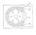
- FIG. 3 is a diagram schematically showing the configuration of the blow molding apparatus 30 of the first embodiment.
- the blow molding apparatus 30 of the first embodiment is an example of the manufacturing apparatus of the peeling container 20, and the peeling container 20 utilizes the retained heat (internal heat amount) at the time of injection molding without cooling the preform 10 to room temperature.
- a hot parison method also referred to as a one-stage method for blow molding is adopted.
- the blow molding apparatus 30 conveys the first injection molding unit 31, the first temperature adjustment unit 32, the second injection molding unit 33, the second temperature adjustment unit 34, the blow molding unit 35, the take-out unit 36, and the like. It includes a mechanism 37.
- the first injection molding unit 31, the first temperature adjustment unit 32, the second injection molding unit 33, the second temperature adjustment unit 34, the blow molding unit 35, and the take-out unit 36 have the same predetermined angle (for example, the same predetermined angle) about the transport mechanism 37. It is arranged at a position rotated by 60 degrees).
- the blow molding apparatus 30 may be configured to omit the first temperature adjusting unit 32 (in this case, each molding station is arranged at a position rotated by 72 degrees around the transfer mechanism 37). Further, the first injection molding unit 31 and the second injection molding unit 33 are provided with a core type elevating mechanism (not shown) above the transport mechanism 37.
- the transfer mechanism 37 includes a rotating plate (transfer plate) 37a that rotates about an axis in the direction perpendicular to the paper surface of FIG. On the rotating plate 37a, one or more neck molds 37b (not shown in FIG. 3) holding the neck portion 13 of the preform 10 (or the neck portion 21 of the peeling container 20) are arranged at predetermined angles.
- the transport mechanism 37 rotates the rotating plate 37a to form the preform 10 (or the peeling container 20) held by the neck mold 37b in the first injection molding unit 31, the first temperature adjusting unit 32, and the second injection molding unit.
- the unit 33, the second temperature adjusting unit 34, the blow molding unit 35, and the take-out unit 36 are conveyed in this order.
- the transport mechanism 37 can also raise and lower the rotary plate 37a, and also performs operations related to mold closing and mold opening (release) in the first injection molding unit 31 and the second injection molding unit 33.
- the first injection molding unit 31 includes a cavity mold 40, a core mold 41, and a hot runner mold 42, and cooperates with a neck mold 37b that is conveyed during molding to manufacture the first layer 11 of the preform 10.
- the cavity type 40 is composed of a first cavity type 40A on the opening side (upper side) and a second cavity type 40B on the bottom surface side (lower side).
- a first injection device 38 that supplies a first resin material to the hot runner mold 42 is connected to the first injection molding unit 31.
- the cavity type 40 and the hot runner type 42 are fixed to the machine base of the blow molding apparatus 30 in an integrated state.
- the core type 41 is fixed to the core type elevating mechanism.
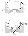
- FIG. 4 (a) and 4 (b) show a first injection molding unit 31 for molding the first layer 11 of the preform 10 of the first embodiment.
- FIG. 5A is a diagram showing the vicinity of the bottom of the first layer 11 in the first injection molding unit 31 of the first embodiment.
- FIG. 6A is a perspective view showing a configuration example of the cavity type 40 (second cavity type 40B) of the first injection molding unit 31.
- the cavity type 40 defines (defines) the shape of the outer circumference of the first layer 11.
- the first cavity mold 40A is a mold facing the opening side of the cavity mold 40 (the side that comes into contact with the neck mold 37b when the mold is closed), and defines the shape of the outer periphery of the body of the first layer 11.
- the second cavity mold 40B is a mold facing the bottom surface side (the side that comes into contact with the hot runner mold 42) of the cavity mold 40, and defines the shape of the outer periphery of the bottom portion of the first layer 11.
- the second cavity type 40B further includes a gate portion 40Ba that guides the resin material from the hot runner type 42 to the cavity surface.
- the hot runner type 42 has a resin supply unit 42a (resin flow passage 42a) for introducing the first resin material plasticized (melted) by the first injection device 38 into the second cavity type 40B.
- the core mold 41 is a mold that defines the shape of the inner peripheral side of the first layer 11, and is inserted into the inner peripheral side of the cavity mold 40 from above.
- the neck type 37b defines the outer shape of the neck portion 13 of the preform 10 (first layer 11).
- the cavity mold 40 and the core mold 41 and the neck mold 37b of the transport mechanism 37 are molded and closed to form the first layer.
- Form 11 mold spaces are formed. Then, by pouring the first resin material from the bottom of the mold space through the hot runner mold 42, the first layer 11 of the preform 10 is manufactured in the first injection molding portion 31.
- a first protrusion 44 such as a columnar, tapered columnar, or prismatic column is provided at a predetermined position.
- a first protrusion 44 is arranged at intervals in the radial direction from the center of the bottom where the resin supply portion 42a is located.
- the amount of protrusion of the first protrusion 44 from the cavity reference surface of the second cavity type 40B (the cavity surface that defines the shape of the lower end side of the outer peripheral surface of the bottom of the first layer 11).
- h1 has substantially the same dimensions as the thickness of the first layer 11.
- the tip of the first protrusion 44 faces the surface of the core mold 41 (arranged in the vicinity of the surface of the core mold 41).
- the first protrusion 44 forms a circular recess 11a in the first layer 11 at a position corresponding to the recess 17 of the preform 10.
- the recess 11a of the first layer 11 may penetrate the first layer 11 or may have a thin film formed between the core mold 41 and the first protrusion 44.
- the recess 11a of the first layer 11 formed by the first injection molding portion 31 is also referred to as a first recess.
- the resin supply portion 42a of the hot runner type 42 has a valve pin (a rod-shaped member that opens and closes the resin supply portion 42a) that can move in the axial direction to a position close to the core mold 41. 43 is provided.
- the valve pin 43 is housed inside the hot runner mold 42 until the first resin material is filled in the mold space, and after the first resin material is filled in the mold space, the end of the gate portion 40Ba on the cavity side is open. It protrudes to a position closer to the core mold 41.
- a thin film portion 18 having a thickness thinner than the peripheral portion of the resin material can be formed in the center of the bottom portion of the first layer 11.
- the neck mold 37b of the transport mechanism 37 is not opened and the first layer 11 of the preform 10 is held and conveyed as it is.
- the number of preforms 10 simultaneously molded by the first injection molding unit 31 that is, the number of peeling containers 20 that can be simultaneously molded by the blow molding apparatus 30) can be appropriately set.
- the first temperature adjusting unit 32 adjusts the temperature of a temperature adjusting mold (a heating pot or a temperature adjusting pot (temperature adjusting pot) for adjusting the temperature of the first layer 11 from the outside) and the first layer 11 from the inside (not shown). It is equipped with a heating rod, a temperature control rod (temperature control rod), or an air introduction rod).
- the first temperature adjusting unit 32 cools (or heats) the first layer 11 which is in a high temperature state after injection molding by accommodating it in a temperature adjusting mold kept at a predetermined temperature.
- the first temperature adjusting unit 32 also has a function of adjusting the temperature distribution of the first layer 11 to a predetermined state before being conveyed to the second injection molding unit 33.
- the second injection molding unit 33 includes a cavity mold 50, a core mold 51, and a hot runner mold 52, and cooperates with a neck mold 37b conveyed at the time of molding to provide a second layer 12 on the inner peripheral side of the first layer 11. Injection molding.
- the cavity type 50 is composed of a first cavity type 50A on the opening side (upper side) and a second cavity type 50B on the bottom surface side (lower side).
- a second injection device 39 that supplies a second resin material to the hot runner mold 52 is connected to the second injection molding unit 33.
- FIG. 4C shows a second injection molding unit 33 that molds the second layer 12 of the preform 10.
- FIG. 5B is a diagram showing the vicinity of the bottom of the preform 10 in the second injection molding unit 33.
- the cavity mold 50 is a mold for accommodating the first layer 11.
- the first cavity mold 50A is a mold facing the opening side of the cavity mold 50 and accommodates the body portion of the first layer 11.
- the second cavity mold 50B is a mold facing the bottom surface side of the cavity mold 50, and accommodates the bottom portion of the first layer 11.
- the second cavity type 50B further includes a gate portion 50Ba that guides the resin material from the hot runner type 52 to the cavity surface.
- the hot runner type 52 has a resin supply unit 52a (resin flow passage 52a) for introducing a second resin material plasticized (melted) by the second injection device 39 at the center of the bottom portion.
- the core mold 51 is a mold that defines the shape of the inner peripheral side of the second layer 12, and is inserted into the inner peripheral side of the cavity mold 50 from above.
- the neck type 37b defines the upper end surface (top surface) of the neck portion 13 of the preform 10 (second layer 12).
- the hot runner type 52 may have a structure having a valve pin like the hot runner type 42. However, the position of the valve pin when closing the second resin material is set to a position that does not protrude from the opening end on the cavity side of the gate portion 50Ba.
- the second injection molding unit 33 accommodates the first layer 11 of the preform 10 injection-molded by the first injection molding unit 31.
- the second injection molding portion 33 When the second injection molding portion 33 is closed, a mold space is formed between the inner peripheral side of the first layer 11 and the surface of the core mold 51.
- the second layer 12 was laminated on the inner peripheral side of the first layer 11 by pouring the second resin material from the bottom of the mold space through the hot runner mold 52.
- the preform 10 is formed.
- a preform is formed at a predetermined position corresponding to the first protrusion 44 of the first injection molding portion 31.
- a second protrusion 54 such as a columnar shape corresponding to the shape of the recess 17 of 10 is provided. The second protrusion 54 is inserted into the recess 11a of the first layer 11 when the first layer 11 is housed in the second injection molding portion 33.
- the basic configuration of the protrusions and the like in the second cavity mold 50B is substantially the same as that of the second cavity mold 40B of the first injection molding portion 31.
- the second protrusion 54 from the cavity reference surface of the second cavity type 50B (the cavity surface that abuts on the lower end side region of the bottom outer peripheral surface of the first layer 11).
- the protrusion amount h2 of is larger than the thickness of the first layer 11. That is, the protrusion amount h2 of the second protrusion 54 is larger than the protrusion amount h1 of the first protrusion 44 (h2> h1). Therefore, when the second injection molding portion 33 is closed, the tip of the second protrusion 54 penetrates the recess 11a of the first layer 11 and projects to the inner peripheral side of the first layer 11.
- the protrusion amount h2 of the second protrusion 54 is set to be smaller than the thickness of the preform 10. That is, in the injection molding by the second injection molding portion 33, the second resin material flows between the core mold 51 and the second protrusion 54, so that the second protrusion 54 penetrates the second layer 12. No holes are formed.
- the cavity end portion 53 connected to the gate portion 50Ba is formed with a curved diameter-expanded portion (bulging portion) extending toward the mold space. ing. Therefore, in the vicinity of the center of the bottom portion of the second injection molding portion 33, a gap is generated between the curved surface of the cavity end portion 53 of the cavity mold 50 and the outer peripheral surface of the first layer 11. A second resin material flows into the above gap during injection molding. As a result, a locking portion 19 projecting outward from the opening 16 in the radial direction can be integrally formed with the second layer 12 on the outside of the first layer 11.
- the second temperature adjusting unit 34 adjusts the temperature of a mold unit (heating pot or temperature adjusting pot (temperature adjusting pot) for adjusting the temperature of the preform 20 from the outside) and the preform 20 from the inside (not shown). It is equipped with a heating rod, a temperature control rod (temperature control rod), or an air introduction rod).
- the second temperature adjusting unit 34 accommodates the preform 10 conveyed from the second injection molding unit 33 in a mold unit kept at a predetermined temperature to equalize the temperature and remove the unbalanced temperature of the preform 10. The temperature is adjusted to a temperature suitable for the final blow (for example, about 90 ° C to 105 ° C).
- the second temperature adjusting unit 34 also has a function of cooling the preform 10 in a high temperature state after injection molding.
- the blow molding unit 35 blow-molds the preform 10 whose temperature has been adjusted by the second temperature adjusting unit 34 to manufacture the peeling container 20.
- the blow molding unit 35 includes a blow cavity type, which is a pair of split molds corresponding to the shape of the release container 20, a bottom type, a drawing rod, and an air introduction member (all not shown).
- the blow molding unit 35 blow molds while stretching the preform 10. As a result, the preform 10 is shaped into a blow cavity type shape, and the peeling container 20 can be manufactured.
- the take-out unit 36 is configured to open the neck portion 21 of the release container 20 manufactured by the blow molding unit 35 from the neck mold 37b and take out the release container 20 to the outside of the blow molding apparatus 30.
- FIG. 7 is a flowchart showing the process of the manufacturing method of the peeling container 20.
- Step S101 First injection molding step
- the first resin material from the first injection device 38 is placed in the mold space formed by the cavity mold 40, the core mold 41, and the neck mold 37b. Is injected, and the first layer 11 of the preform 10 is molded. At this time, the first protrusion 44 forms a recess 11a at the bottom of the first layer 11.
- the first injection molding section 31 is opened and the first layer is released.
- the rotating plate 37a of the transport mechanism 37 rotates by a predetermined angle, and the first layer 11 of the preform 10 held by the neck mold 37b retains heat during injection molding. It is conveyed to the first temperature adjusting unit 32 in a state of being contained.
- Step S102 First temperature adjustment step
- the first layer 11 of the preform 10 is housed in the temperature adjusting mold, and the cooling of the first layer 11 and the adjustment of the temperature distribution (leveling and removing uneven temperature) are performed. Will be done.
- the first temperature adjustment step may be omitted.
- the rotating plate 37a of the transport mechanism 37 rotates by a predetermined angle, and the temperature-adjusted first layer 11 held by the neck mold 37b is the second injection molding portion. It is transported to 33.
- Step S103 Second injection molding step
- the first layer 11 of the preform 10 is housed in the second injection molding unit 33, and the injection molding of the second layer 12 is performed.
- a mold space is provided between the inner peripheral side of the first layer 11 and the surface of the core mold 51 facing the inner circumference of the first layer 11.
- the formed mold space is filled with a second resin material from the hot runner mold 52.
- the thin film portion 18 is formed at the bottom of the first layer 11, the thin film portion 18 is broken by the injection pressure of the second resin material to form an opening 16 at the bottom, and the opening 16 is formed from the above opening 16.
- the second resin material is guided to the inner peripheral side of the first layer 11.
- the temperature of the second resin material filled in the second injection molding unit 33 is set to a temperature lower than the melting point of the first resin material. Further, the surface temperature of the first layer 11 when the second resin material is filled in the second injection molding unit 33 is cooled to a temperature equal to or lower than the melting point of the second resin material.
- the cavity mold 50 faces the outer peripheral side of the first layer 11, and the shape of the first layer 11 is held from the outer peripheral side by the cavity mold 50. Therefore, even if the second resin material comes into contact with the first layer 11, the thermal deformation of the first layer 11 can be suppressed.
- the recess 17 of the preform 10 is closed with the second resin material. There is no. Further, since the tip of the second protrusion 54 in the second injection molding portion 33 projects to the inner peripheral side of the first layer, the recess 17 of the preform 10 formed by the second protrusion 54 is the first. The shape is such that the surface of the second layer 12 is exposed in the recess 17 through the layer 11.
- the second resin material is allowed to flow into the gap between the curved surface of the cavity end portion 53 adjacent to the gate portion 50Ba of the cavity type 50B and the outer peripheral surface of the first layer 11.
- a locking portion 19 is formed integrally with the second layer 12 on the outside of the first layer 11. When the locking portion 19 is caught on the outside of the first layer 11, the second layer 12 is prevented from coming off with respect to the first layer 11.
- the preform 10 in which the second layer 12 is laminated on the inner peripheral side of the first layer 11 is manufactured by the first injection molding step and the second injection molding step.
- the rotating plate 37a of the transport mechanism 37 rotates by a predetermined angle, and the preform 10 held in the neck mold 37b contains the heat retained during injection molding. Is conveyed to the second temperature adjusting unit 34.
- Step S104 Second temperature adjustment step
- the preform 10 is housed in the temperature adjusting mold unit, and the temperature is adjusted so that the temperature of the preform 10 approaches the temperature suitable for the final blow.
- the rotating plate 37a of the transport mechanism 37 rotates by a predetermined angle, and the temperature-adjusted preform 10 held in the neck mold 37b is transported to the blow molding unit 35.
- Step S105 Blow molding step
- the blow molding unit 35 performs blow molding of the release container 20.
- the blow cavity mold is closed, the preform 10 is housed in the mold space, and the air introduction member (blow core) is lowered, so that the air introduction member is brought into contact with the neck portion 13 of the preform 10.
- the drawing rod is lowered to suppress the bottom portion 15 of the preform 10 from the inner surface, and the preform 10 is stretched on the horizontal axis by supplying blow air from the air introduction member while stretching the vertical axis as necessary. ..
- the preform 10 is bulged and shaped so as to be in close contact with the blow cavity type mold space, and is blow molded into the release container 20.
- Step S106 Container removal step
- the blow cavity mold is opened.
- the release container 20 can be moved from the blow molding unit 35.
- the rotating plate 37a of the transport mechanism 37 rotates by a predetermined angle, and the release container 20 is transported to the take-out unit 36.
- the neck portion 21 of the peeling container 20 is released from the neck mold 37b, and the peeling container 20 is taken out to the outside of the blow molding apparatus 30.
- the waiting times of the first injection molding step, the first temperature adjusting step, the second injection molding step, the second temperature adjusting step, the blow molding step, and the container taking-out step are all the same length. Become. Similarly, the transport time between each step is the same length.
- the first layer 11 (outer layer) of the preform 10 is molded in the first injection molding step, and the opening 16 of the first layer 11 is inside the first layer 11 in the second injection molding step.
- the two-layer structure 12 (inner layer) is injection-molded to produce a two-layer structure preform 10.
- the outer layer can be formed first with a resin material having a high melting point, and then the inner layer can be formed with a resin material having a melting point lower than that of the outer layer.
- the preform 10 having a two-layer structure suitable for the specifications of the peeling container 20 can be manufactured by continuously performing injection molding of the inner layer while the outer layer has the heat retained at the time of injection molding.
- the peeling container 20 is manufactured by a hot parison type blow molding method. Sometimes a suitable preform 10 can be obtained.
- the preform 10 having the above-mentioned two-layer structure is stretch-blow molded to produce the peeling container 20 in a state of having the heat retained at the time of injection molding. Therefore, in the first embodiment, the peeling container 20 having excellent aesthetic appearance, physical strength, and the like can be manufactured by the hot parison type blow molding method. Compared with the cold parison type blow molding, in the first embodiment, it is not necessary to cool the manufactured preform 10 to near room temperature, and the step of reheating the preform 10 is also unnecessary. Therefore, according to the first embodiment, a series of steps from injection molding of the preform 10 to blow molding of the peeling container 20 can be completed in a relatively short time, and the peeling container 20 can be manufactured in a shorter cycle. ..
- the locking portion 19 is integrally formed on the outside of the first layer 11 by the second resin material forming the second layer 12, and the first layer 11 is formed.
- the second layer 12 is prevented from coming off.
- the locking portion 19 comes into contact with the first layer 11 and becomes a resistance to the force in the pulling direction, and becomes an outer layer of the preform 10. The inner layer is less likely to shift.
- the resin material of the inner layer to be filled later unintentionally wraps around to the outer peripheral side. If the outside of the reform is coated, the appearance of the container after blow molding is greatly spoiled.
- a peeling container is manufactured by applying a hot parison type blow molding method, a configuration for suppressing molding defects in which the resin material of the inner layer unintentionally wraps around to the outer peripheral side will be described.
- FIG. 8 is a vertical cross-sectional view of the preform 10 of the second embodiment.
- the bottom portion 15 of the preform 10 of the second embodiment shown in FIG. 8 is formed with a raised portion 12a protruding in a curved shape on the inner peripheral side of the second layer 12.
- the raised portion 12a is a resin pool formed during injection molding of the second resin material, and is formed at a position facing the opening 16 of the first layer 11. Since the configuration of the peeling container 20 in the second embodiment is the same as that in the first embodiment, duplicate description will be omitted.
- the basic configuration of the blow molding apparatus 30 of the second embodiment is the same as that of the blow molding apparatus 30 of the first embodiment shown in FIG. Hereinafter, the differences in the second embodiment will be described.
- FIG. 9 is a diagram showing a manufacturing process of the preform of the second embodiment.
- FIG. 10A is a diagram showing the vicinity of the bottom of the first layer in the first injection molding part of the second embodiment
- FIG. 10B is a preform in the second injection molding part of the second embodiment. It is a figure which shows the vicinity of the bottom of.
- FIG. 9 corresponds to FIG. 4 of the first embodiment
- FIG. 10 corresponds to FIG. 5 of the first embodiment.
- the axial length of the inner peripheral portion of the cavity type 40 corresponding to the bottom surface from the upper end of the body portion of the first layer 11 is set. It is set to L1.
- the axial length of the inner peripheral portion of the cavity type 50 accommodating the bottom surface from the upper end of the body portion of the first layer 11 (Depth) is set to L2, which is shorter than L1 (L1> L2).
- L2 is limited to the deformation margin of the first layer 11 (the amount of compression of the first layer 11 by pushing up the cavity mold 50 or the amount of shrinkage of the first layer 11 due to heat dissipation or the like before the second injection molding process). It is set shorter than L1. That is, the depth of the mold space of the cavity mold 50 accommodating the first layer 11 is shorter than the axial length of the first layer 11.
- a curved recessed portion 51a is formed at the tip of the core mold 51 in the second embodiment.
- the recessed portion 51a faces the outlet of the second resin material located at the center of the second cavity mold 50B, and creates a space for a resin pool between the recessed portion 51a and the opening 16 of the first layer 11.
- the resin pool forms a raised portion 12a on the inner peripheral side of the second layer 12.
- the diameter d2 (diameter of the valve pin) at the tip of the hot runner mold 52 is the hot of the first injection molding section 31. It is set smaller than the diameter of the tip of the runner type 42 (the diameter of the valve pin 43) and the diameter d1 of the opening 16 of the first layer 11. By narrowing the diameter d2 at the tip of the hot runner mold 52 to be smaller than the diameter d1 of the opening 16, the flow velocity of the second resin material injected into the mold space of the second injection molding portion 33 can be increased.
- the steps of the method for manufacturing the peeling container 20 in the second embodiment are the first injection molding step (S101), the first temperature adjusting step (S102), the second injection molding step (S103), and the first step. 2.
- the temperature adjustment step (S104), the blow molding step (S105), and the container take-out step (S106) are included.
- the first injection molding step (S101) and the first temperature adjusting step (S102) of the second embodiment are the same as those of the first embodiment.
- the first layer 11 of the preform 10 is housed in the second injection molding unit 33, and the injection molding of the second layer 12 is performed.
- a mold space is provided between the inner peripheral side of the first layer 11 and the surface of the core mold 51 facing the inner circumference of the first layer 11.
- the formed mold space is filled with a second resin material from the hot runner mold 52.
- the thin film portion 18 is formed at the bottom of the first layer 11, the thin film portion 18 is broken by the injection pressure of the second resin material to form an opening 16 at the bottom, and the opening 16 is formed from the above opening 16.
- the second resin material is guided to the inner peripheral side of the first layer 11.
- the depth of the mold space of the cavity type 50 accommodating the first layer 11 is shorter than the axial length of the first layer 11. Therefore, when the first layer 11 is accommodated in the cavity mold 50, the bottom portion of the first layer 11 is pressed against the bottom surface of the cavity mold 50 to bring them into contact with each other, and a gap is provided between the bottom portion of the first layer 11 and the cavity mold 50. Can be suppressed.
- a space for a resin pool is formed between the opening 16 of the first layer 11 and the recessed portion 51a of the core mold 51.
- the second resin material that has passed through the opening 16 hits the recessed portion 51a of the core mold 51 and is agitated in the space of the resin pool, and then enters the mold space between the inner circumference of the first layer 11 and the surface of the core mold 51. Inflow.
- the fragments of the thin film portion 18 of the first layer 11 are mixed with the high temperature second resin material and melted.
- the fragments of the thin film portion 18 can be dissipated to the extent that they cannot be visually recognized.
- the diameter d2 at the tip of the hot runner type 52 is narrowed down to be smaller than the diameter d1 of the opening 16 of the first layer 11.
- the temperature of the second resin material filled in the second injection molding unit 33 is set to a temperature lower than the melting point of the first resin material. Further, the surface temperature of the first layer 11 when the second resin material is filled in the second injection molding unit 33 is cooled to a temperature equal to or lower than the melting point of the second resin material.
- the cavity mold 50 faces the outer peripheral side of the first layer 11, and the shape of the first layer 11 is held from the outer peripheral side by the cavity mold 50. Therefore, even if the second resin material comes into contact with the first layer 11, the thermal deformation of the first layer 11 can be suppressed.
- the recess 17 of the preform 10 is closed with the second resin material. There is no. Further, since the tip of the second protrusion 54 in the second injection molding portion 33 projects to the inner peripheral side of the first layer, the recess 17 of the preform 10 formed by the second protrusion 54 is the first. The shape is such that the surface of the second layer 12 is exposed in the recess 17 through the layer 11.
- the preform 10 in which the second layer 12 is laminated on the inner peripheral side of the first layer 11 is manufactured by the first injection molding step and the second injection molding step.
- the rotating plate 37a of the transport mechanism 37 rotates by a predetermined angle, and the preform 10 held in the neck mold 37b contains the heat retained during injection molding. Is conveyed to the second temperature adjusting unit 34.
- the second temperature adjustment step (S104), blow molding step (S105), and container take-out step (S106) of the second embodiment are all the same as those of the first embodiment.
- the depth of the mold space of the cavity mold 50 accommodating the first layer 11 is shorter than the axial length of the first layer 11. Therefore, the bottom portion of the first layer 11 is pressed against the bottom surface of the cavity mold 50, and a gap between the bottom portion of the first layer 11 and the cavity mold 50 is suppressed. Therefore, according to the present embodiment, it becomes difficult for the second resin material to flow between the first layer 11 and the cavity mold 50, and molding defects occur in which the second resin material covers the outer periphery of the first layer 11. It is suppressed.
- the recessed portion 51a is provided at the tip of the core mold 51, and the fragments of the thin film portion 18 are mixed and melted by stirring the fragments of the thin film portion 18 with the high temperature second resin material at the time of injection molding to melt the thin film. Makes it easier to dissipate the debris of part 18. As a result, in the preform 10 and the peeling container 20, it is possible to reduce the possibility that the debris of the thin film portion 18 remains in the inner layer and the appearance is spoiled.
- FIG. 6B shows an example in which the first protrusions 44 are provided at two places in the second cavity type 40B of the first injection molding part 31.
- the two first protrusions 44 are arranged at positions symmetrical with respect to the central axis with an interval of 180 °.
- the number of the first protrusions 44 may be three or more. At that time, it is preferable that each of the first protrusions 44 is arranged in a point-symmetrical positional relationship with respect to the central axis.
Landscapes
- Engineering & Computer Science (AREA)
- Manufacturing & Machinery (AREA)
- Mechanical Engineering (AREA)
- Physics & Mathematics (AREA)
- Geometry (AREA)
- Blow-Moulding Or Thermoforming Of Plastics Or The Like (AREA)
- Processing And Handling Of Plastics And Other Materials For Molding In General (AREA)
- Injection Moulding Of Plastics Or The Like (AREA)
- Moulds For Moulding Plastics Or The Like (AREA)
Priority Applications (7)
| Application Number | Priority Date | Filing Date | Title |
|---|---|---|---|
| CN202180030109.8A CN115427214B (zh) | 2020-04-06 | 2021-04-06 | 剥离容器的制造方法及制造装置 |
| CN202511332951.3A CN120941701A (zh) | 2020-04-06 | 2021-04-06 | 剥离容器的制造方法及制造装置 |
| EP21785429.8A EP4134221A4 (en) | 2020-04-06 | 2021-04-06 | Method and device for manufacturing delamination container |
| JP2022514082A JP7447242B2 (ja) | 2020-04-06 | 2021-04-06 | 剥離容器の製造方法および製造装置 |
| US17/917,364 US12304131B2 (en) | 2020-04-06 | 2021-04-06 | Manufacturing method and manufacturing apparatus for delamination container |
| JP2024028949A JP7642892B2 (ja) | 2020-04-06 | 2024-02-28 | 剥離容器の製造方法および製造装置 |
| JP2025028721A JP2025071319A (ja) | 2020-04-06 | 2025-02-26 | 樹脂製容器の製造方法および製造装置 |
Applications Claiming Priority (4)
| Application Number | Priority Date | Filing Date | Title |
|---|---|---|---|
| JP2020068160 | 2020-04-06 | ||
| JP2020068138 | 2020-04-06 | ||
| JP2020-068138 | 2020-04-06 | ||
| JP2020-068160 | 2020-04-06 |
Publications (1)
| Publication Number | Publication Date |
|---|---|
| WO2021206083A1 true WO2021206083A1 (ja) | 2021-10-14 |
Family
ID=78023656
Family Applications (1)
| Application Number | Title | Priority Date | Filing Date |
|---|---|---|---|
| PCT/JP2021/014605 Ceased WO2021206083A1 (ja) | 2020-04-06 | 2021-04-06 | 剥離容器の製造方法および製造装置 |
Country Status (5)
| Country | Link |
|---|---|
| US (1) | US12304131B2 (https=) |
| EP (1) | EP4134221A4 (https=) |
| JP (3) | JP7447242B2 (https=) |
| CN (2) | CN115427214B (https=) |
| WO (1) | WO2021206083A1 (https=) |
Citations (3)
| Publication number | Priority date | Publication date | Assignee | Title |
|---|---|---|---|---|
| JPH01153453A (ja) * | 1987-12-10 | 1989-06-15 | Toyo Seikan Kaisha Ltd | 耐圧耐熱容器及びその製造方法 |
| JP2001105478A (ja) * | 1999-10-08 | 2001-04-17 | Taisei Kako Co Ltd | 積層ボトルの製造方法、並びに、積層剥離容器の製造装置 |
| JP5267901B2 (ja) | 2007-06-29 | 2013-08-21 | 株式会社吉野工業所 | ダイレクトブロー成形法による合成樹脂製二重容器 |
Family Cites Families (11)
| Publication number | Priority date | Publication date | Assignee | Title |
|---|---|---|---|---|
| JP3330677B2 (ja) | 1993-06-10 | 2002-09-30 | 日精エー・エス・ビー機械株式会社 | 成形方法およびその成形装置 |
| JP2000043126A (ja) | 1998-07-31 | 2000-02-15 | Toppan Printing Co Ltd | 延伸ブロー成形用の二層構成プリフォーム |
| US20040022977A1 (en) * | 1998-11-30 | 2004-02-05 | Sandstrom Erland R. | Injection blow-molded disposable tumbler and method of making same |
| JP4485627B2 (ja) * | 1999-10-08 | 2010-06-23 | 大成化工株式会社 | 積層剥離ボトル、並びに、ポンプ容器 |
| US6649121B1 (en) | 1999-10-08 | 2003-11-18 | Taisei Kako Co., Ltd. | Method of producing laminated bottles having peelable inner layer |
| JP2002326221A (ja) * | 2001-04-27 | 2002-11-12 | Toppan Printing Co Ltd | 二層プリフォームの製造方法 |
| JP4357183B2 (ja) * | 2003-02-14 | 2009-11-04 | 大成化工株式会社 | 積層剥離ボトル及びその製造方法 |
| JP2006344427A (ja) | 2005-06-07 | 2006-12-21 | Nissan Motor Co Ltd | 固体高分子型燃料電池 |
| WO2008125698A1 (es) * | 2007-04-11 | 2008-10-23 | Molmasa Aplicaciones Técnicas, S.L. | Molde y procedimiento para fabricación de preformas bicomponente por sobremoldeo de inyección, y preforma bicomponente obtenida |
| KR101445522B1 (ko) * | 2014-01-14 | 2014-10-01 | 김윤우 | 보틀엔드, 혼합용기 및 그것의 제조방법 |
| EP3112109B1 (en) * | 2015-06-29 | 2018-05-23 | The Procter and Gamble Company | Improved preforms and processes for making bag in bottle containers |
-
2021
- 2021-04-06 EP EP21785429.8A patent/EP4134221A4/en active Pending
- 2021-04-06 WO PCT/JP2021/014605 patent/WO2021206083A1/ja not_active Ceased
- 2021-04-06 US US17/917,364 patent/US12304131B2/en active Active
- 2021-04-06 CN CN202180030109.8A patent/CN115427214B/zh active Active
- 2021-04-06 CN CN202511332951.3A patent/CN120941701A/zh active Pending
- 2021-04-06 JP JP2022514082A patent/JP7447242B2/ja active Active
-
2024
- 2024-02-28 JP JP2024028949A patent/JP7642892B2/ja active Active
-
2025
- 2025-02-26 JP JP2025028721A patent/JP2025071319A/ja active Pending
Patent Citations (3)
| Publication number | Priority date | Publication date | Assignee | Title |
|---|---|---|---|---|
| JPH01153453A (ja) * | 1987-12-10 | 1989-06-15 | Toyo Seikan Kaisha Ltd | 耐圧耐熱容器及びその製造方法 |
| JP2001105478A (ja) * | 1999-10-08 | 2001-04-17 | Taisei Kako Co Ltd | 積層ボトルの製造方法、並びに、積層剥離容器の製造装置 |
| JP5267901B2 (ja) | 2007-06-29 | 2013-08-21 | 株式会社吉野工業所 | ダイレクトブロー成形法による合成樹脂製二重容器 |
Non-Patent Citations (1)
| Title |
|---|
| See also references of EP4134221A4 |
Also Published As
| Publication number | Publication date |
|---|---|
| US12304131B2 (en) | 2025-05-20 |
| JPWO2021206083A1 (https=) | 2021-10-14 |
| CN120941701A (zh) | 2025-11-14 |
| JP2025071319A (ja) | 2025-05-02 |
| JP7447242B2 (ja) | 2024-03-11 |
| JP2024051121A (ja) | 2024-04-10 |
| US20230150182A1 (en) | 2023-05-18 |
| EP4134221A4 (en) | 2024-05-08 |
| CN115427214A (zh) | 2022-12-02 |
| JP7642892B2 (ja) | 2025-03-10 |
| EP4134221A1 (en) | 2023-02-15 |
| CN115427214B (zh) | 2025-10-10 |
Similar Documents
| Publication | Publication Date | Title |
|---|---|---|
| JP7457077B2 (ja) | 首曲がり容器の製造方法、温度調整用金型、ブロー成形装置およびブロー成形方法 | |
| CN114599499A (zh) | 用于生产剥离容器的方法和用于生产剥离容器的设备 | |
| WO2020262595A1 (ja) | 樹脂製成形品の製造装置、樹脂製成形品の製造方法、及び樹脂製成形品 | |
| JP7353471B2 (ja) | 剥離容器の製造方法および製造装置 | |
| JP7705994B2 (ja) | 金型ユニットおよびブロー成形装置 | |
| EP4617028A1 (en) | Peelable container, preform, and manufacturing method and manufacturing device for peelable container | |
| EP4134317B1 (en) | Peeling container and method for manufacturing peeling container | |
| WO2021206083A1 (ja) | 剥離容器の製造方法および製造装置 | |
| EP4257330B1 (en) | Method and apparatus for manufacturing resin container | |
| KR20260002789A (ko) | 박리 용기, 박리 용기의 제조 방법 및 제조 장치 | |
| WO2023171603A1 (ja) | 樹脂製容器の製造方法、温度調整用金型ユニットおよび樹脂製容器の製造装置 |
Legal Events
| Date | Code | Title | Description |
|---|---|---|---|
| 121 | Ep: the epo has been informed by wipo that ep was designated in this application |
Ref document number: 21785429 Country of ref document: EP Kind code of ref document: A1 |
|
| ENP | Entry into the national phase |
Ref document number: 2022514082 Country of ref document: JP Kind code of ref document: A |
|
| NENP | Non-entry into the national phase |
Ref country code: DE |
|
| ENP | Entry into the national phase |
Ref document number: 2021785429 Country of ref document: EP Effective date: 20221107 |
|
| WWG | Wipo information: grant in national office |
Ref document number: 202217062994 Country of ref document: IN |
|
| WWG | Wipo information: grant in national office |
Ref document number: 17917364 Country of ref document: US |
|
| WWG | Wipo information: grant in national office |
Ref document number: 202180030109.8 Country of ref document: CN |