WO2021201215A1 - デブロッキングフィルタ制御装置及びプログラム - Google Patents
デブロッキングフィルタ制御装置及びプログラム Download PDFInfo
- Publication number
- WO2021201215A1 WO2021201215A1 PCT/JP2021/014144 JP2021014144W WO2021201215A1 WO 2021201215 A1 WO2021201215 A1 WO 2021201215A1 JP 2021014144 W JP2021014144 W JP 2021014144W WO 2021201215 A1 WO2021201215 A1 WO 2021201215A1
- Authority
- WO
- WIPO (PCT)
- Prior art keywords
- unit
- bit depth
- parameter
- deblocking filter
- conversion
- Prior art date
- Legal status (The legal status is an assumption and is not a legal conclusion. Google has not performed a legal analysis and makes no representation as to the accuracy of the status listed.)
- Ceased
Links
Images


Classifications
-
- H—ELECTRICITY
- H04—ELECTRIC COMMUNICATION TECHNIQUE
- H04N—PICTORIAL COMMUNICATION, e.g. TELEVISION
- H04N19/00—Methods or arrangements for coding, decoding, compressing or decompressing digital video signals
- H04N19/10—Methods or arrangements for coding, decoding, compressing or decompressing digital video signals using adaptive coding
- H04N19/102—Methods or arrangements for coding, decoding, compressing or decompressing digital video signals using adaptive coding characterised by the element, parameter or selection affected or controlled by the adaptive coding
- H04N19/117—Filters, e.g. for pre-processing or post-processing
-
- H—ELECTRICITY
- H04—ELECTRIC COMMUNICATION TECHNIQUE
- H04N—PICTORIAL COMMUNICATION, e.g. TELEVISION
- H04N19/00—Methods or arrangements for coding, decoding, compressing or decompressing digital video signals
- H04N19/10—Methods or arrangements for coding, decoding, compressing or decompressing digital video signals using adaptive coding
- H04N19/134—Methods or arrangements for coding, decoding, compressing or decompressing digital video signals using adaptive coding characterised by the element, parameter or criterion affecting or controlling the adaptive coding
- H04N19/136—Incoming video signal characteristics or properties
-
- H—ELECTRICITY
- H04—ELECTRIC COMMUNICATION TECHNIQUE
- H04N—PICTORIAL COMMUNICATION, e.g. TELEVISION
- H04N19/00—Methods or arrangements for coding, decoding, compressing or decompressing digital video signals
- H04N19/10—Methods or arrangements for coding, decoding, compressing or decompressing digital video signals using adaptive coding
- H04N19/134—Methods or arrangements for coding, decoding, compressing or decompressing digital video signals using adaptive coding characterised by the element, parameter or criterion affecting or controlling the adaptive coding
- H04N19/146—Data rate or code amount at the encoder output
-
- H—ELECTRICITY
- H04—ELECTRIC COMMUNICATION TECHNIQUE
- H04N—PICTORIAL COMMUNICATION, e.g. TELEVISION
- H04N19/00—Methods or arrangements for coding, decoding, compressing or decompressing digital video signals
- H04N19/10—Methods or arrangements for coding, decoding, compressing or decompressing digital video signals using adaptive coding
- H04N19/169—Methods or arrangements for coding, decoding, compressing or decompressing digital video signals using adaptive coding characterised by the coding unit, i.e. the structural portion or semantic portion of the video signal being the object or the subject of the adaptive coding
- H04N19/17—Methods or arrangements for coding, decoding, compressing or decompressing digital video signals using adaptive coding characterised by the coding unit, i.e. the structural portion or semantic portion of the video signal being the object or the subject of the adaptive coding the unit being an image region, e.g. an object
- H04N19/176—Methods or arrangements for coding, decoding, compressing or decompressing digital video signals using adaptive coding characterised by the coding unit, i.e. the structural portion or semantic portion of the video signal being the object or the subject of the adaptive coding the unit being an image region, e.g. an object the region being a block, e.g. a macroblock
-
- H—ELECTRICITY
- H04—ELECTRIC COMMUNICATION TECHNIQUE
- H04N—PICTORIAL COMMUNICATION, e.g. TELEVISION
- H04N19/00—Methods or arrangements for coding, decoding, compressing or decompressing digital video signals
- H04N19/10—Methods or arrangements for coding, decoding, compressing or decompressing digital video signals using adaptive coding
- H04N19/169—Methods or arrangements for coding, decoding, compressing or decompressing digital video signals using adaptive coding characterised by the coding unit, i.e. the structural portion or semantic portion of the video signal being the object or the subject of the adaptive coding
- H04N19/184—Methods or arrangements for coding, decoding, compressing or decompressing digital video signals using adaptive coding characterised by the coding unit, i.e. the structural portion or semantic portion of the video signal being the object or the subject of the adaptive coding the unit being bits, e.g. of the compressed video stream
-
- H—ELECTRICITY
- H04—ELECTRIC COMMUNICATION TECHNIQUE
- H04N—PICTORIAL COMMUNICATION, e.g. TELEVISION
- H04N19/00—Methods or arrangements for coding, decoding, compressing or decompressing digital video signals
- H04N19/80—Details of filtering operations specially adapted for video compression, e.g. for pixel interpolation
- H04N19/82—Details of filtering operations specially adapted for video compression, e.g. for pixel interpolation involving filtering within a prediction loop
-
- H—ELECTRICITY
- H04—ELECTRIC COMMUNICATION TECHNIQUE
- H04N—PICTORIAL COMMUNICATION, e.g. TELEVISION
- H04N19/00—Methods or arrangements for coding, decoding, compressing or decompressing digital video signals
- H04N19/85—Methods or arrangements for coding, decoding, compressing or decompressing digital video signals using pre-processing or post-processing specially adapted for video compression
- H04N19/86—Methods or arrangements for coding, decoding, compressing or decompressing digital video signals using pre-processing or post-processing specially adapted for video compression involving reduction of coding artifacts, e.g. of blockiness
Definitions
- the present invention relates to a deblocking filter control device and a program.
- the original image is divided into blocks, and prediction processing, conversion processing, and quantization processing are applied for each divided block, so block distortion may occur in the decoded image. Therefore, in a video coding method such as HEVC (High Efficiency Video Coding) and / or VVC (Versatile Video Coding) standard draft (hereinafter referred to as VVC) described in Non-Patent Document 1, an in-loop filter is applied to the decoded image. A deblocking filter that reduces block distortion by applying processing has been introduced.
- the deblocking filter in HEVC and / or VVC was applied to the pixel value of the region near the boundary of the decoded image before the deblocking filter processing and the conversion block straddling the boundary for each boundary of the block to be converted (conversion block).
- Application control is performed according to the quantization parameters and the like. There is “t C " as one of the parameter values for controlling the filter strength in such a deblocking filter process.
- the table of t C values corresponding to the quantization parameter QP defined in HEVC has a bit depth of 8 bits.
- the value corresponding to the video signal of is stored.
- a value corresponding to the 10-bit video signal is specified in the t C table.
- Non-Patent Document 1 describes that the conversion process is performed by bit shift and offset as shown in the following equation.
- the deblocking filter control device is a deblocking filter that controls deblocking filter processing on a decoded image in a coding device that encodes a video signal or a decoding device that decodes a coded video signal. It is a control device, and is converted by converting the parameter value based on the input bit depth, which is the bit depth of the video signal, and the parameter derivation unit that derives the parameter value that controls the filter strength in the deblocking filter processing.
- a parameter conversion unit that outputs a parameter value is provided, and when the input bit depth is smaller than the specified bit depth, the parameter conversion unit performs bit shift on the result of adding an offset value to the parameter value.
- the conversion parameter value is output by the above, and the offset value is changed based on the input bit depth.
- the gist of the program according to the second aspect is to make the computer function as a deblocking filter control device according to the first aspect.
- Non-Patent Document 1 does not function correctly under predetermined conditions.
- the conversion formula described in Non-Patent Document 1 cannot perform appropriate conversion processing when the bit depth of the input video is 9 bits, so that the pixel value is corrected by unintended deblocking filter processing. There is a concern that it may cause deterioration of the image.
- an object of the present disclosure is to make it possible to appropriately control the deblocking filter processing according to the bit depth of the input video.
- the coding device and the decoding device according to the embodiment will be described with reference to the drawings.
- the coding device and the decoding device according to the embodiment encode and decode moving images represented by MPEG (Moving Picture Experts Group), respectively.
- MPEG Motion Picture Experts Group
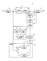
- FIG. 1 is a diagram showing a configuration of a coding device 1 according to the present embodiment.
- the coding device 1 is a device that performs coding in block units obtained by dividing an image.
- the coding apparatus 1 synthesizes a block dividing unit 100, a subtracting unit 110, a conversion / quantization unit 120, an entropy coding unit 130, an inverse quantization / inverse conversion unit 140, and the like. It has a unit 150, a deblocking filter 160, a deblocking filter control device 161, a memory 170, and a prediction unit 180.
- the block division unit 100 divides the input image in units of frames (or pictures) constituting the moving image into a plurality of image blocks, and outputs the image block obtained by the division to the subtraction unit 110.
- the size of the image block is, for example, 32 ⁇ 32 pixels, 16 ⁇ 16 pixels, 8 ⁇ 8 pixels, 4 ⁇ 4 pixels, or the like.
- the shape of the image block is not limited to a square and may be a rectangle (non-square).
- the image block is a unit for coding by the coding device 1 (encoding target block) and a unit for decoding by the decoding device (decoding target block). Such an image block is sometimes called a CU (Coding Unit).
- the bit depth of the video signal input to the block division unit 100 (hereinafter referred to as "input bit depth") is basically 10 bits. However, the input bit depth can be changed within the range of 8 bits to 14 bits.
- the value (number of bits) indicating the input bit depth may be output from the block division unit 100 to the deblocking filter control device 161 or deblocking from the functional unit (so-called preprocessing unit) in the previous stage of the block division unit 100. It may be output to the filter control device 161.
- the block division unit 100 divides the luminance signal and the color difference signal into blocks.
- the luminance block and the color difference block are not particularly distinguished, they are simply referred to as a coded block.
- the subtraction unit 110 calculates a prediction residual representing a difference (error) between the coding target block output from the block division unit 100 and the prediction block obtained by predicting the coding target block by the prediction unit 180.
- the subtraction unit 110 calculates the prediction residual by subtracting each pixel value of the prediction block from each pixel value of the block, and outputs the calculated prediction residual to the conversion / quantization unit 120.
- the conversion / quantization unit 120 performs conversion processing and quantization processing in block units.
- the conversion / quantization unit 120 includes a conversion unit 121 and a quantization unit 122.
- the conversion unit 121 performs conversion processing on the predicted residual output from the subtraction unit 110, calculates a conversion coefficient for each frequency component, and outputs the calculated conversion coefficient to the quantization unit 122.
- the conversion process is a process of converting a signal in the pixel region into a signal in the frequency domain. Refers to the conversion, etc., in which is converted to an integer. Further, the conversion process may include a conversion skip that adjusts by scaling or the like without converting the signal in the pixel region into the signal in the frequency domain.
- the quantization unit 122 quantizes the conversion coefficient output from the conversion unit 121 using the quantization parameter and the quantization matrix, and transfers the quantized conversion coefficient to the entropy coding unit 130 and the inverse quantization / inverse conversion unit 140. Output. Further, the quantization unit 122 provides information on the quantization process (specifically, information on the quantization parameters and the quantization matrix used in the quantization process) to the entropy coding unit 130, the inverse quantization unit 141, and the inverse quantization unit 141. Output to the deblocking filter control device 161.
- the quantization parameter is a parameter in which one value is set for one block.
- the quantization parameter is a parameter that is commonly applied to each conversion coefficient in the block, and is a parameter that determines the roughness (step size) of quantization.
- the quantization matrix is a matrix consisting of values set for each component in one block.
- the quantization matrix is a matrix consisting of values (weighting coefficients) set for each component of the i ⁇ j element according to the block size, and is quantum for each component of the conversion coefficient from low frequency to high frequency. It is used to adjust the roughness of the quantization.
- the entropy coding unit 130 performs entropy coding on the conversion coefficient output from the quantization unit 122, performs data compression to generate a coded stream (bit stream), and encodes the coded stream into the coding device 1. Output to the outside of.
- Huffman coding and / or CABAC Context-based Adaptive Binary Arithmetic Coding; context-adaptive binary arithmetic coding
- the entropy coding unit 130 acquires information such as the size and shape of each coded block and the bit depth from the block dividing unit 100, acquires information related to the quantization process from the quantization unit 122, and predicts unit 180.
- Information on prediction (for example, information on prediction mode and motion vector) is obtained from, and the information is also encoded.
- the inverse quantization / inverse transformation unit 140 performs the inverse quantization processing and the inverse transformation processing in block units.
- the inverse quantization / inverse conversion unit 140 includes an inverse quantization unit 141 and an inverse conversion unit 142.
- the inverse quantization unit 141 performs the inverse quantization process corresponding to the quantization process performed by the quantization unit 122. Specifically, the inverse quantization unit 141 restores the conversion coefficient by inversely quantizing the conversion coefficient output from the quantization unit 122 using the quantization parameter and the quantization matrix, and restores the conversion coefficient. Is output to the inverse conversion unit 142.
- the reverse conversion unit 142 performs the reverse conversion process corresponding to the conversion process performed by the conversion unit 121. For example, when the conversion unit 121 performs the DCT, the inverse conversion unit 142 performs the inverse DCT.
- the inverse transformation unit 142 performs an inverse transformation process on the conversion coefficient output from the inverse quantization unit 141 to restore the predicted residual, and outputs the restored predicted residual, which is the restored predicted residual, to the synthesis unit 150. do.
- the synthesis unit 150 synthesizes the restoration prediction residual output from the inverse conversion unit 142 with the prediction block output from the prediction unit 180 in pixel units.
- the synthesizing unit 150 adds each pixel value of the restored prediction residual and each pixel value of the predicted block to restore (decode) the coded block, and deblocks the decoded image (restored block) of the restored block unit. Output to 160.
- the deblocking filter 160 performs filter processing on the block boundary of two blocks including a restoration block and an adjacent block adjacent to the restoration block, and outputs the restored block after the filtering processing to the memory 170.
- the filter processing is a processing for reducing signal deterioration caused by processing in block units, and is a filtering processing for smoothing a signal gap at a block boundary between two adjacent blocks.
- the deblocking filter 160 is generally configured as a low-pass filter that moderates signal fluctuations.
- FIG. 2 is a diagram showing an operation example of the deblocking filter 160 according to the present embodiment.
- the deblocking filter 160 shows an example in which the filter processing is performed on the block boundary of each block of 8 ⁇ 8 pixels, but the block boundary of each block of 4 ⁇ 4 pixels is targeted. Filtering may be performed. Further, the deblocking filter 160 performs filter processing in units of 4 rows or 4 columns.
- the blocks P and Q shown in FIG. 2 show an example in which the deblocking filter 160 is one unit of the filter processing and the block size is 4 ⁇ 4 pixels. Each of the blocks P and Q may be referred to as a subblock.
- the deblocking filter control device 161 controls the deblocking filter 160. Specifically, the deblocking filter control device 161 controls the boundary strength (Bs: Boundary strength) indicating whether or not the block boundary of the target block pair is filtered, and the filter strength of the deblocking filter 160.
- the boundary strength Bs refers to a parameter for determining whether or not to apply the filtering process and the type of the filtering process.
- the control of whether or not the filtering process is performed can be regarded as the control of whether the boundary strength Bs is 1 or more or zero.
- the deblocking filter control device 161 is based on the fluctuation of the pixel value in the region near the boundary of the target block pair, the prediction mode, the quantization parameter, and the motion vector value used for the motion compensation prediction (inter-prediction), and the deblocking filter 160 To control.
- the deblocking filter control device 161 controls the filter strength of the deblocking filter 160 based on the input bit depth and the quantization parameters used in the quantization processing and the inverse quantization processing. In the following, it is assumed that the coded block or its subblock is the block P, and the adjacent block or its subblock is the block Q.
- the deblocking filter control device 161 determines the boundary strength Bs based on, for example, Table 1 below.
- the value of the boundary strength Bs is one of 0, 1, and 2.
- the boundary strength of the luminance signal and the color difference signal block may be calculated respectively, or the combination of the boundary intensity of the luminance signal and the color difference signal block may be determined as one boundary intensity.
- the deblocking filter control device 161 sets the value of Bs to 2 when the intra prediction is applied to at least one of the blocks P and Q.
- the deblocking filter control device 161 has a Bs value when inter-prediction is applied to both blocks P and Q and at least one of the following conditions (a) to (c) is satisfied. Is set to 1, and in other cases, the Bs value is set to 0.
- At least one of blocks P and Q contains a significant conversion coefficient (that is, a non-zero conversion coefficient).
- the deblocking filter control device 161 controls the deblocking filter 160 so that the boundary between the blocks P and Q is not filtered when the value of the boundary strength Bs is 0.
- the deblocking filter control device 161 has a parameter derivation unit 161a.
- the parameter derivation unit 161a includes a quantization parameter Qp P used in the quantization process and the dequantization process for the block P, a quantization parameter Qp Q used in the quantization process and the dequantization process for the block Q, and an offset value. based on the PqOffset, deriving the parameter value for controlling the filter strength of the deblocking filter 160 (threshold) beta and t C '.
- the parameter derivation unit 161a calculates the variable qP by, for example, the following equation.
- This formula is basically a calculation formula for calculating the average of the quantization parameter Qp P of the block P and the quantization parameter Qp Q of the block Q.
- the parameter derivation unit 161a calculates Q for deriving the parameter value ⁇ by, for example, the following equation.
- slice_beta_offset_div2 is one of the parameters signaling to the decoding device 2.
- the parameter derivation unit 161a for example, by the following equation to calculate the Q for deriving a parameter value t C '.
- slice_tc_offset_div2 is one of the parameters signaling to the decoding device 2.
- the parameter derivation unit 161a is the following Table 2, to derive the parameter values ⁇ and t C 'from Q calculated respectively.
- t C ' is a value corresponding to a video signal of 10-bit bit depth.
- the deblocking filter control device 161 further includes a parameter conversion unit 161b.
- Parameter conversion section 161b outputs the converted parameter values t C by converting the parameter value t C 'based on the input bit-depth.
- Conversion parameter values t C represents the value of t C 'obtained by performing the conversion process to correspond to the input bit depth.
- the parameter conversion unit 161b when the input bit depth is smaller than the specified bit depth, the parameter conversion unit 161b converts the conversion parameter value t C by performing a bit shift on the result of adding the offset value to the parameter value t C'. Output.
- the parameter conversion unit 161b changes the offset value based on the input bit depth. The details of the operation of the parameter conversion unit 161b will be described later.
- the deblocking filter control device 161 further includes a filter strength control unit 161c.
- the filter intensity control unit 161c controls the filter intensity of the deblocking filter 160 based on the value of the boundary intensity Bs and the parameter values ⁇ and t C.
- the filter strength control unit 161c may control the deblocking filter 160 so as to perform the filter processing only when the following equation is satisfied (see FIG. 2). ..
- the filter strength control unit 161c may apply a strong filter when all of the following conditional expressions are satisfied, and may apply a weak filter in other cases (see FIG. 2).
- the memory 170 stores the restoration block output from the deblocking filter 160 as a decoded image in frame units.
- the memory 170 outputs the stored decoded image to the prediction unit 180.
- the prediction unit 180 generates a prediction block corresponding to the coded target block by performing prediction processing in block units, and outputs the generated prediction block to the subtraction unit 110 and the synthesis unit 150.
- the prediction unit 180 includes an inter-prediction unit 181, an intra-prediction unit 182, and a switching unit 183.
- the inter-prediction unit 181 uses the decoded image stored in the memory 170 as a reference image, calculates a motion vector by a method such as block matching, predicts a block to be encoded, and generates an inter-prediction block.
- the inter-prediction block is output to the switching unit 183.
- the inter-prediction unit 181 selects the optimum inter-prediction method from inter-prediction using a plurality of reference images (typically bi-prediction) and inter-prediction using one reference image (one-way prediction). Inter-prediction is performed using the selected inter-prediction method.
- the inter-prediction unit 181 outputs information (motion vector, etc.) related to the inter-prediction to the entropy coding unit 130 and the deblocking filter control device 161.
- the intra prediction unit 182 selects the optimum intra prediction mode to be applied to the coded target block from a plurality of intra prediction modes, and predicts the coded target block using the selected intra prediction mode.
- the intra prediction unit 182 generates an intra prediction block by referring to the decoded pixel value adjacent to the coded target block among the decoded images stored in the memory 170, and outputs the generated intra prediction block to the switching unit 183. do. Further, the intra prediction unit 182 outputs information regarding the selected intra prediction mode to the entropy coding unit 130 and the deblocking filter control device 161.
- the switching unit 183 switches between the inter prediction block output from the inter prediction unit 181 and the intra prediction block output from the intra prediction unit 182, and outputs one of the prediction blocks to the subtraction unit 110 and the synthesis unit 150.
- FIG. 3 is a diagram showing the operation of the parameter conversion unit 161b according to the present embodiment.
- step S1 the parameter conversion unit 161b determines whether or not the input bit depth is smaller than the specified bit depth.
- the parameter value is t C '
- the offset value is ofs
- the input bit depth is BitDepth
- the specified bit depth is b
- the conversion parameter value is t C.
- the defined bit depth b is assumed to be 10 bits.
- step S2 the parameter conversion unit 161b calculates the offset value ofs by the following formula.
- step S3 the parameter conversion unit 161b calculates the conversion parameter value t C by the following equation.
- step S4 the parameter conversion unit 161b calculates the conversion parameter value t C by the following equation.
- Non-Patent Document 1 does not consider the case where the input bit depth is 9 bits.
- the conversion formula described in Non-Patent Document 1 applied to 9-bit video signal the results in 1-bit shift to the then obtained by adding 2 to the value of the original t C ', issues that do not proper value be.
- FIG. 4 is a diagram showing a configuration of a decoding device 2 according to the present embodiment.
- the decoding device 2 is a device that decodes the decoding target block from the coded stream.
- the decoding device 2 includes an entropy decoding unit 200, an inverse quantization / inverse conversion unit 210, a synthesis unit 220, a deblocking filter 230, a deblocking filter control device 231 and a memory 240. , And a prediction unit 250.
- the entropy decoding unit 200 decodes the coded stream generated by the coding device 1 and decodes various signaling information. Specifically, the entropy decoding unit 200 acquires information on the quantization process applied to the decoding target block, and outputs the acquired information to the inverse quantization unit 211 and the deblocking filter control device 231. Further, the entropy decoding unit 200 acquires information related to the prediction applied to the decoding target block (for example, prediction type information, motion vector information), and outputs the acquired information to the prediction unit 250 and the deblocking filter control device 231. ..
- the entropy decoding unit 200 decodes the coded stream, acquires the quantized conversion coefficient, and outputs the acquired conversion coefficient to the inverse quantization / inverse conversion unit 210 (inverse quantization unit 211).
- the inverse quantization / inverse transformation unit 210 performs the inverse quantization process and the inverse transformation process in block units.
- the inverse quantization / inverse conversion unit 210 includes an inverse quantization unit 211 and an inverse conversion unit 212.
- the inverse quantization unit 211 performs the inverse quantization process corresponding to the quantization process performed by the quantization unit 122 of the coding device 1.
- the inverse quantization unit 211 restores and restores the conversion coefficient of the decoding target block by inversely quantizing the quantization conversion coefficient output from the entropy decoding unit 200 using the quantization parameter and the quantization matrix.
- the conversion coefficient is output to the inverse conversion unit 212.
- the inverse conversion unit 212 performs an inverse conversion process corresponding to the conversion process performed by the conversion unit 121 of the coding device 1.
- the inverse conversion unit 212 performs inverse transformation processing on the conversion coefficient output from the inverse quantization unit 211 to restore the predicted residual, and outputs the restored predicted residual (restored predicted residual) to the synthesis unit 220. do.
- the synthesizing unit 220 restores (decodes) the decoding target block by synthesizing the prediction residual output from the inverse conversion unit 212 and the prediction block output from the prediction unit 250 on a pixel-by-pixel basis, and restores (decodes) the restoration block. Output to the deblocking filter 230.
- the deblocking filter 230 operates in the same manner as the deblocking filter 160 of the coding device 1.
- the deblocking filter control device 231 operates in the same manner as the deblocking filter control device 161 of the coding device 1 based on the information (bit depth information, etc.) output from the entropy decoding unit 200. Specifically, the deblocking filter control device 231 has a parameter derivation unit 231a, a parameter conversion unit 231b, and a filter intensity control unit 231c, similarly to the deblocking filter control device 161 of the coding device 1.
- the parameter conversion unit 231b operates according to the flow of FIG.
- the memory 240 stores the restoration block output from the deblocking filter 230 as a decoded image in frame units.
- the memory 240 outputs a frame-by-frame decoded image to the outside of the decoding device 2.
- the prediction unit 250 makes a prediction in block units.
- the prediction unit 250 includes an inter-prediction unit 251, an intra-prediction unit 252, and a switching unit 253.
- the inter-prediction unit 251 uses the decoded image stored in the memory 240 as a reference image to predict the decoding target block by inter-prediction.
- the inter-prediction unit 251 generates an inter-prediction block by performing inter-prediction using the motion vector information output from the entropy decoding unit 200, and outputs the generated inter-prediction block to the switching unit 253.
- the intra prediction unit 252 refers to the reference pixel adjacent to the decoding target block among the decoded images stored in the memory 240, and predicts the decoding target block by intra prediction based on the information output from the entropy decoding unit 200. .. Then, the intra prediction unit 252 generates an intra prediction block, and outputs the generated intra prediction block to the switching unit 253.
- the switching unit 253 switches between the inter prediction block output from the inter prediction unit 251 and the intra prediction block output from the intra prediction unit 252, and outputs one of the prediction blocks to the synthesis unit 220.
- a program that causes a computer to execute each process performed by the coding device 1 may be provided.
- a program that causes a computer to execute each process performed by the decoding device 2 may be provided.
- the program may be recorded on a computer-readable medium.
- Computer-readable media allow you to install programs on your computer.
- the computer-readable medium on which the program is recorded may be a non-transient recording medium.
- the non-transient recording medium is not particularly limited, but may be, for example, a recording medium such as a CD-ROM or a DVD-ROM.
- a circuit that executes each process performed by the coding device 1 may be integrated, and the coding device 1 may be configured by a semiconductor integrated circuit (chipset, SoC).
- a circuit that executes each process performed by the decoding device 2 may be integrated, and the decoding device 2 may be configured by a semiconductor integrated circuit (chipset, SoC).
Landscapes
- Engineering & Computer Science (AREA)
- Multimedia (AREA)
- Signal Processing (AREA)
- Compression Or Coding Systems Of Tv Signals (AREA)
- Arrangement And Driving Of Transmission Devices (AREA)
- Detergent Compositions (AREA)
- Oscillators With Electromechanical Resonators (AREA)
- Telephone Function (AREA)
Priority Applications (11)
| Application Number | Priority Date | Filing Date | Title |
|---|---|---|---|
| BR112022005312-6A BR112022005312B1 (pt) | 2020-04-02 | 2021-04-01 | Dispositivo de controle do filtro de desbloqueio |
| EP21781209.8A EP4131953A4 (en) | 2020-04-02 | 2021-04-01 | CONTROL DEVICE AND PROGRAM FOR UNLOCKING A FILTER |
| KR1020227009132A KR102448226B1 (ko) | 2020-04-02 | 2021-04-01 | 디블로킹 필터 제어 장치 및 프로그램 |
| CN202180005434.9A CN114503565B (zh) | 2020-04-02 | 2021-04-01 | 去块滤波控制装置及程序 |
| KR1020227032954A KR102741218B1 (ko) | 2020-04-02 | 2021-04-01 | 디블로킹 필터 제어 장치 및 프로그램 |
| JP2022512696A JP7080424B2 (ja) | 2020-04-02 | 2021-04-01 | デブロッキングフィルタ制御装置及びプログラム |
| CN202310113842.7A CN116132669B (zh) | 2020-04-02 | 2021-04-01 | 去块滤波控制装置及程序产品 |
| MX2022003395A MX2022003395A (es) | 2020-04-02 | 2021-04-01 | Dispositivo y programa de control de filtro de desbloqueo. |
| US17/655,745 US11595645B2 (en) | 2020-04-02 | 2022-03-21 | Deblocking filter control device and program |
| JP2022084865A JP7357721B2 (ja) | 2020-04-02 | 2022-05-24 | デブロッキングフィルタ制御装置及びプログラム |
| US18/160,785 US11991356B2 (en) | 2020-04-02 | 2023-01-27 | Deblocking filter control device and program |
Applications Claiming Priority (2)
| Application Number | Priority Date | Filing Date | Title |
|---|---|---|---|
| JP2020-067043 | 2020-04-02 | ||
| JP2020067043 | 2020-04-02 |
Related Child Applications (1)
| Application Number | Title | Priority Date | Filing Date |
|---|---|---|---|
| US17/655,745 Continuation US11595645B2 (en) | 2020-04-02 | 2022-03-21 | Deblocking filter control device and program |
Publications (1)
| Publication Number | Publication Date |
|---|---|
| WO2021201215A1 true WO2021201215A1 (ja) | 2021-10-07 |
Family
ID=77929578
Family Applications (1)
| Application Number | Title | Priority Date | Filing Date |
|---|---|---|---|
| PCT/JP2021/014144 Ceased WO2021201215A1 (ja) | 2020-04-02 | 2021-04-01 | デブロッキングフィルタ制御装置及びプログラム |
Country Status (7)
| Country | Link |
|---|---|
| US (2) | US11595645B2 (https=) |
| EP (1) | EP4131953A4 (https=) |
| JP (2) | JP7080424B2 (https=) |
| KR (2) | KR102448226B1 (https=) |
| CN (2) | CN116132669B (https=) |
| MX (2) | MX2022003395A (https=) |
| WO (1) | WO2021201215A1 (https=) |
Families Citing this family (1)
| Publication number | Priority date | Publication date | Assignee | Title |
|---|---|---|---|---|
| WO2021201215A1 (ja) * | 2020-04-02 | 2021-10-07 | 日本放送協会 | デブロッキングフィルタ制御装置及びプログラム |
Citations (2)
| Publication number | Priority date | Publication date | Assignee | Title |
|---|---|---|---|---|
| WO2013064654A1 (en) * | 2011-11-03 | 2013-05-10 | Panasonic Corporation | Efficient rounding for deblocking |
| JP2020067043A (ja) | 2018-10-25 | 2020-04-30 | 中川産業株式会社 | エンジンの消音装置の製造方法 |
Family Cites Families (11)
| Publication number | Priority date | Publication date | Assignee | Title |
|---|---|---|---|---|
| KR101826215B1 (ko) * | 2011-06-23 | 2018-03-22 | 후아웨이 테크놀러지 컴퍼니 리미티드 | 오프셋 복호 장치, 오프셋 부호화 장치, 화상 필터 장치 및 데이터 구조 |
| US9185404B2 (en) * | 2011-10-07 | 2015-11-10 | Qualcomm Incorporated | Performing transform dependent de-blocking filtering |
| DK2834980T3 (en) * | 2012-04-05 | 2017-07-03 | ERICSSON TELEFON AB L M (publ) | Sample adaptive filtering with offsets |
| US9591302B2 (en) * | 2012-07-02 | 2017-03-07 | Microsoft Technology Licensing, Llc | Use of chroma quantization parameter offsets in deblocking |
| US20150016516A1 (en) * | 2013-07-15 | 2015-01-15 | Samsung Electronics Co., Ltd. | Method for intra prediction improvements for oblique modes in video coding |
| CN109792541A (zh) * | 2016-10-05 | 2019-05-21 | 瑞典爱立信有限公司 | 用于视频译码的去振铃滤波器 |
| CN116320498A (zh) | 2016-11-28 | 2023-06-23 | 韩国电子通信研究院 | 用于滤波的方法和装置 |
| CN114979635B (zh) * | 2017-10-09 | 2023-10-27 | 佳能株式会社 | 用于对样本块进行滤波的方法、装置和存储介质 |
| US10616577B2 (en) * | 2017-10-16 | 2020-04-07 | Intel Corporation | Adaptive video deblocking |
| CN119324983A (zh) * | 2018-03-30 | 2025-01-17 | 英迪股份有限公司 | 图像编码/解码方法以及存储介质 |
| WO2021201215A1 (ja) | 2020-04-02 | 2021-10-07 | 日本放送協会 | デブロッキングフィルタ制御装置及びプログラム |
-
2021
- 2021-04-01 WO PCT/JP2021/014144 patent/WO2021201215A1/ja not_active Ceased
- 2021-04-01 CN CN202310113842.7A patent/CN116132669B/zh active Active
- 2021-04-01 MX MX2022003395A patent/MX2022003395A/es unknown
- 2021-04-01 KR KR1020227009132A patent/KR102448226B1/ko active Active
- 2021-04-01 EP EP21781209.8A patent/EP4131953A4/en active Pending
- 2021-04-01 JP JP2022512696A patent/JP7080424B2/ja active Active
- 2021-04-01 KR KR1020227032954A patent/KR102741218B1/ko active Active
- 2021-04-01 CN CN202180005434.9A patent/CN114503565B/zh active Active
-
2022
- 2022-03-18 MX MX2023001472A patent/MX2023001472A/es unknown
- 2022-03-21 US US17/655,745 patent/US11595645B2/en active Active
- 2022-05-24 JP JP2022084865A patent/JP7357721B2/ja active Active
-
2023
- 2023-01-27 US US18/160,785 patent/US11991356B2/en active Active
Patent Citations (2)
| Publication number | Priority date | Publication date | Assignee | Title |
|---|---|---|---|---|
| WO2013064654A1 (en) * | 2011-11-03 | 2013-05-10 | Panasonic Corporation | Efficient rounding for deblocking |
| JP2020067043A (ja) | 2018-10-25 | 2020-04-30 | 中川産業株式会社 | エンジンの消音装置の製造方法 |
Non-Patent Citations (4)
| Title |
|---|
| BENJAMIN BROSS , JIANLE CHEN , SHAN LIU , YE-KUI WANG: "Versatile Video Coding (Draft 8)", 17. JVET MEETING; 20200107 - 20200117; BRUSSELS; (THE JOINT VIDEO EXPLORATION TEAM OF ISO/IEC JTC1/SC29/WG11 AND ITU-T SG.16 ), no. JVET-Q2001-vE, 12 March 2020 (2020-03-12), pages 1 - 510, XP030285390 * |
| K. ANDERSSON, J. ENHORN: "Non-CE5: Deblocking tC table defined for 10-bit video", 15. JVET MEETING; 20190703 - 20190712; GOTHENBURG; (THE JOINT VIDEO EXPLORATION TEAM OF ISO/IEC JTC1/SC29/WG11 AND ITU-T SG.16 ), 20 June 2019 (2019-06-20), XP030205720 * |
| S. IWAMURA, S. NEMOTO, A. ICHIGAYA (NHK): "Cleanup of tC value derivation process for deblocking filter", 130. MPEG MEETING; 20200420 - 20200424; ALPBACH; (MOTION PICTURE EXPERT GROUP OR ISO/IEC JTC1/SC29/WG11), 6 April 2020 (2020-04-06), XP030285974 * |
| See also references of EP4131953A4 |
Also Published As
| Publication number | Publication date |
|---|---|
| CN116132669A (zh) | 2023-05-16 |
| BR112022005312A2 (pt) | 2022-11-29 |
| JP7080424B2 (ja) | 2022-06-03 |
| CN114503565B (zh) | 2023-03-10 |
| CN114503565A (zh) | 2022-05-13 |
| MX2022003395A (es) | 2023-03-02 |
| KR102741218B1 (ko) | 2024-12-10 |
| US11991356B2 (en) | 2024-05-21 |
| KR102448226B1 (ko) | 2022-09-27 |
| EP4131953A1 (en) | 2023-02-08 |
| KR20220133321A (ko) | 2022-10-04 |
| US11595645B2 (en) | 2023-02-28 |
| US20220217338A1 (en) | 2022-07-07 |
| US20230179765A1 (en) | 2023-06-08 |
| MX2023001472A (es) | 2023-03-06 |
| JPWO2021201215A1 (https=) | 2021-10-07 |
| JP7357721B2 (ja) | 2023-10-06 |
| JP2022105653A (ja) | 2022-07-14 |
| EP4131953A4 (en) | 2024-05-22 |
| KR20220039847A (ko) | 2022-03-29 |
| CN116132669B (zh) | 2026-04-03 |
Similar Documents
| Publication | Publication Date | Title |
|---|---|---|
| US12137254B2 (en) | Encoding device, decoding device and program | |
| JP2025124883A (ja) | デブロッキングフィルタ装置、復号装置、及びプログラム | |
| US20250097419A1 (en) | Encoding device, decoding device and program | |
| JP7357721B2 (ja) | デブロッキングフィルタ制御装置及びプログラム | |
| JP2024107426A (ja) | 復号装置及び復号方法 | |
| JP7474772B2 (ja) | 符号化装置、復号装置、及びプログラム | |
| WO2021045059A1 (ja) | 符号化装置、復号装置、及びプログラム | |
| WO2021251400A1 (ja) | 復号装置及びプログラム |
Legal Events
| Date | Code | Title | Description |
|---|---|---|---|
| 121 | Ep: the epo has been informed by wipo that ep was designated in this application |
Ref document number: 21781209 Country of ref document: EP Kind code of ref document: A1 |
|
| ENP | Entry into the national phase |
Ref document number: 20227009132 Country of ref document: KR Kind code of ref document: A |
|
| ENP | Entry into the national phase |
Ref document number: 2022512696 Country of ref document: JP Kind code of ref document: A |
|
| REG | Reference to national code |
Ref country code: BR Ref legal event code: B01A Ref document number: 112022005312 Country of ref document: BR |
|
| NENP | Non-entry into the national phase |
Ref country code: DE |
|
| ENP | Entry into the national phase |
Ref document number: 2021781209 Country of ref document: EP Effective date: 20221102 |
|
| ENP | Entry into the national phase |
Ref document number: 112022005312 Country of ref document: BR Kind code of ref document: A2 Effective date: 20220322 |