WO2021201093A1 - ガスタービンの燃焼器、及び、ガスタービン - Google Patents
ガスタービンの燃焼器、及び、ガスタービン Download PDFInfo
- Publication number
- WO2021201093A1 WO2021201093A1 PCT/JP2021/013809 JP2021013809W WO2021201093A1 WO 2021201093 A1 WO2021201093 A1 WO 2021201093A1 JP 2021013809 W JP2021013809 W JP 2021013809W WO 2021201093 A1 WO2021201093 A1 WO 2021201093A1
- Authority
- WO
- WIPO (PCT)
- Prior art keywords
- fuel nozzle
- fuel
- combustor
- nozzle group
- throttle
- Prior art date
- Legal status (The legal status is an assumption and is not a legal conclusion. Google has not performed a legal analysis and makes no representation as to the accuracy of the status listed.)
- Ceased
Links
Images





Classifications
-
- F—MECHANICAL ENGINEERING; LIGHTING; HEATING; WEAPONS; BLASTING
- F23—COMBUSTION APPARATUS; COMBUSTION PROCESSES
- F23R—GENERATING COMBUSTION PRODUCTS OF HIGH PRESSURE OR HIGH VELOCITY, e.g. GAS-TURBINE COMBUSTION CHAMBERS
- F23R3/00—Continuous combustion chambers using liquid or gaseous fuel
- F23R3/28—Continuous combustion chambers using liquid or gaseous fuel characterised by the fuel supply
- F23R3/34—Feeding into different combustion zones
- F23R3/343—Pilot flames, i.e. fuel nozzles or injectors using only a very small proportion of the total fuel to insure continuous combustion
-
- F—MECHANICAL ENGINEERING; LIGHTING; HEATING; WEAPONS; BLASTING
- F23—COMBUSTION APPARATUS; COMBUSTION PROCESSES
- F23R—GENERATING COMBUSTION PRODUCTS OF HIGH PRESSURE OR HIGH VELOCITY, e.g. GAS-TURBINE COMBUSTION CHAMBERS
- F23R3/00—Continuous combustion chambers using liquid or gaseous fuel
- F23R3/02—Continuous combustion chambers using liquid or gaseous fuel characterised by the air-flow or gas-flow configuration
- F23R3/16—Continuous combustion chambers using liquid or gaseous fuel characterised by the air-flow or gas-flow configuration with devices inside the flame tube or the combustion chamber to influence the air or gas flow
-
- F—MECHANICAL ENGINEERING; LIGHTING; HEATING; WEAPONS; BLASTING
- F02—COMBUSTION ENGINES; HOT-GAS OR COMBUSTION-PRODUCT ENGINE PLANTS
- F02C—GAS-TURBINE PLANTS; AIR INTAKES FOR JET-PROPULSION PLANTS; CONTROLLING FUEL SUPPLY IN AIR-BREATHING JET-PROPULSION PLANTS
- F02C7/00—Features, components parts, details or accessories, not provided for in, or of interest apart form groups F02C1/00 - F02C6/00; Air intakes for jet-propulsion plants
- F02C7/22—Fuel supply systems
-
- F—MECHANICAL ENGINEERING; LIGHTING; HEATING; WEAPONS; BLASTING
- F02—COMBUSTION ENGINES; HOT-GAS OR COMBUSTION-PRODUCT ENGINE PLANTS
- F02C—GAS-TURBINE PLANTS; AIR INTAKES FOR JET-PROPULSION PLANTS; CONTROLLING FUEL SUPPLY IN AIR-BREATHING JET-PROPULSION PLANTS
- F02C7/00—Features, components parts, details or accessories, not provided for in, or of interest apart form groups F02C1/00 - F02C6/00; Air intakes for jet-propulsion plants
- F02C7/22—Fuel supply systems
- F02C7/228—Dividing fuel between various burners
-
- F—MECHANICAL ENGINEERING; LIGHTING; HEATING; WEAPONS; BLASTING
- F02—COMBUSTION ENGINES; HOT-GAS OR COMBUSTION-PRODUCT ENGINE PLANTS
- F02C—GAS-TURBINE PLANTS; AIR INTAKES FOR JET-PROPULSION PLANTS; CONTROLLING FUEL SUPPLY IN AIR-BREATHING JET-PROPULSION PLANTS
- F02C9/00—Controlling gas-turbine plants; Controlling fuel supply in air- breathing jet-propulsion plants
- F02C9/26—Control of fuel supply
- F02C9/32—Control of fuel supply characterised by throttling of fuel
- F02C9/34—Joint control of separate flows to main and auxiliary burners
-
- F—MECHANICAL ENGINEERING; LIGHTING; HEATING; WEAPONS; BLASTING
- F23—COMBUSTION APPARATUS; COMBUSTION PROCESSES
- F23R—GENERATING COMBUSTION PRODUCTS OF HIGH PRESSURE OR HIGH VELOCITY, e.g. GAS-TURBINE COMBUSTION CHAMBERS
- F23R3/00—Continuous combustion chambers using liquid or gaseous fuel
- F23R3/02—Continuous combustion chambers using liquid or gaseous fuel characterised by the air-flow or gas-flow configuration
- F23R3/04—Air inlet arrangements
- F23R3/10—Air inlet arrangements for primary air
- F23R3/12—Air inlet arrangements for primary air inducing a vortex
-
- F—MECHANICAL ENGINEERING; LIGHTING; HEATING; WEAPONS; BLASTING
- F23—COMBUSTION APPARATUS; COMBUSTION PROCESSES
- F23R—GENERATING COMBUSTION PRODUCTS OF HIGH PRESSURE OR HIGH VELOCITY, e.g. GAS-TURBINE COMBUSTION CHAMBERS
- F23R3/00—Continuous combustion chambers using liquid or gaseous fuel
- F23R3/28—Continuous combustion chambers using liquid or gaseous fuel characterised by the fuel supply
- F23R3/34—Feeding into different combustion zones
-
- F—MECHANICAL ENGINEERING; LIGHTING; HEATING; WEAPONS; BLASTING
- F23—COMBUSTION APPARATUS; COMBUSTION PROCESSES
- F23R—GENERATING COMBUSTION PRODUCTS OF HIGH PRESSURE OR HIGH VELOCITY, e.g. GAS-TURBINE COMBUSTION CHAMBERS
- F23R3/00—Continuous combustion chambers using liquid or gaseous fuel
- F23R3/42—Continuous combustion chambers using liquid or gaseous fuel characterised by the arrangement or form of the flame tubes or combustion chambers
- F23R3/46—Combustion chambers comprising an annular arrangement of several essentially tubular flame tubes within a common annular casing or within individual casings
-
- F—MECHANICAL ENGINEERING; LIGHTING; HEATING; WEAPONS; BLASTING
- F05—INDEXING SCHEMES RELATING TO ENGINES OR PUMPS IN VARIOUS SUBCLASSES OF CLASSES F01-F04
- F05D—INDEXING SCHEME FOR ASPECTS RELATING TO NON-POSITIVE-DISPLACEMENT MACHINES OR ENGINES, GAS-TURBINES OR JET-PROPULSION PLANTS
- F05D2220/00—Application
- F05D2220/30—Application in turbines
- F05D2220/32—Application in turbines in gas turbines
-
- F—MECHANICAL ENGINEERING; LIGHTING; HEATING; WEAPONS; BLASTING
- F05—INDEXING SCHEMES RELATING TO ENGINES OR PUMPS IN VARIOUS SUBCLASSES OF CLASSES F01-F04
- F05D—INDEXING SCHEME FOR ASPECTS RELATING TO NON-POSITIVE-DISPLACEMENT MACHINES OR ENGINES, GAS-TURBINES OR JET-PROPULSION PLANTS
- F05D2240/00—Components
- F05D2240/35—Combustors or associated equipment
-
- F—MECHANICAL ENGINEERING; LIGHTING; HEATING; WEAPONS; BLASTING
- F05—INDEXING SCHEMES RELATING TO ENGINES OR PUMPS IN VARIOUS SUBCLASSES OF CLASSES F01-F04
- F05D—INDEXING SCHEME FOR ASPECTS RELATING TO NON-POSITIVE-DISPLACEMENT MACHINES OR ENGINES, GAS-TURBINES OR JET-PROPULSION PLANTS
- F05D2270/00—Control
- F05D2270/01—Purpose of the control system
- F05D2270/08—Purpose of the control system to produce clean exhaust gases
- F05D2270/082—Purpose of the control system to produce clean exhaust gases with as little NOx as possible
-
- F—MECHANICAL ENGINEERING; LIGHTING; HEATING; WEAPONS; BLASTING
- F05—INDEXING SCHEMES RELATING TO ENGINES OR PUMPS IN VARIOUS SUBCLASSES OF CLASSES F01-F04
- F05D—INDEXING SCHEME FOR ASPECTS RELATING TO NON-POSITIVE-DISPLACEMENT MACHINES OR ENGINES, GAS-TURBINES OR JET-PROPULSION PLANTS
- F05D2270/00—Control
- F05D2270/01—Purpose of the control system
- F05D2270/14—Purpose of the control system to control thermoacoustic behaviour in the combustion chambers
-
- F—MECHANICAL ENGINEERING; LIGHTING; HEATING; WEAPONS; BLASTING
- F23—COMBUSTION APPARATUS; COMBUSTION PROCESSES
- F23R—GENERATING COMBUSTION PRODUCTS OF HIGH PRESSURE OR HIGH VELOCITY, e.g. GAS-TURBINE COMBUSTION CHAMBERS
- F23R2900/00—Special features of, or arrangements for continuous combustion chambers; Combustion processes therefor
- F23R2900/00013—Reducing thermo-acoustic vibrations by active means
-
- F—MECHANICAL ENGINEERING; LIGHTING; HEATING; WEAPONS; BLASTING
- F23—COMBUSTION APPARATUS; COMBUSTION PROCESSES
- F23R—GENERATING COMBUSTION PRODUCTS OF HIGH PRESSURE OR HIGH VELOCITY, e.g. GAS-TURBINE COMBUSTION CHAMBERS
- F23R2900/00—Special features of, or arrangements for continuous combustion chambers; Combustion processes therefor
- F23R2900/00014—Reducing thermo-acoustic vibrations by passive means, e.g. by Helmholtz resonators
Definitions
- This disclosure relates to a gas turbine combustor and a gas turbine.
- a combustor used in a gas turbine includes, for example, a fuel nozzle capable of supplying fuel and a cylinder having a combustion region formed inside through which a combustion gas generated by combustion of the fuel can flow.
- the fuel supplied from the fuel nozzle becomes fuel gas by combustion, and drives a turbine provided on the downstream side via the combustion region of the cylinder.
- combustion vibration may occur due to the interaction between heat generation due to fuel combustion and pressure fluctuation during partial load operation where the operating load is smaller than during rated operation.
- a plurality of fuel nozzles of a gas turbine combustor are classified into a group having a large fuel injection amount and a group having a small fuel injection amount, and both are arranged asymmetrically.
- the temperature of the combustion gas is relatively low, so that the flame formation region formed by the injected fuel expands to the downstream side, and the carbon monoxide emission amount. Will increase.
- At least one aspect of the present disclosure has been made in view of the above circumstances, and a gas turbine combustor and a gas turbine capable of suitably suppressing the generation of carbon monoxide while preventing combustion vibration during partial load operation.
- the purpose is to provide.
- the gas turbine combustor is used to solve the above problems.
- the first fuel nozzle group and the second fuel nozzle group which include fuel nozzles capable of supplying fuel and have fuel supply systems that can be controlled independently of each other.
- a first fuel nozzle group that partially extends along the circumferential direction so as to correspond to one of the first fuel nozzle group and the second fuel nozzle group, and protrudes inward in the radial direction from the inner peripheral surface of the cylinder.
- a gas turbine combustor and a gas turbine capable of suitably suppressing the generation of carbon monoxide while preventing combustion vibration during partial load operation.
- FIG. 1 It is an overall block diagram of the gas turbine which concerns on at least one Embodiment of this disclosure. It is sectional drawing which shows the combustor of FIG. 1 together with the peripheral structure. It is an enlarged view of the area L of FIG. It is a schematic diagram which shows the plurality of fuel nozzles of FIG. 3 from the downstream side along the combustor axis. It is sectional drawing which shows typically the flame formed in the cylinder body at the time of partial load operation in the combustor which concerns on a comparative example. It is a figure which shows the distribution of the temperature and the concentration of carbon monoxide on the broken line of FIG. FIG.
- FIG. 5 is a cross-sectional view schematically showing a flame formed in a cylinder during a partial load operation in a combustor according to some embodiments of the present disclosure. It is an enlarged view which shows the 1st diaphragm part of FIG. 7 from the side. It is a perspective view which shows by extracting the 1st diaphragm part of FIG. 7 by itself. It is a figure which shows the distribution of the temperature and the concentration of carbon monoxide corresponding to FIG. 7. It is a figure which shows an example of the 1st diaphragm part including the grooved diaphragm piece. It is a figure which shows the grooved diaphragm piece of FIG.
- FIG. 7 It is a side view of the cylinder which transparently shows the 1st throttle part and the 2nd throttle part of FIG. It is a schematic diagram which shows the plurality of fuel nozzles of FIG. 13 from the downstream side along the combustor axis. It is a figure which shows the distribution of the temperature and the concentration of carbon monoxide corresponding to FIG. It is a figure which shows an example of the 2nd diaphragm part including the grooved diaphragm piece. It is a figure which shows the grooved diaphragm piece of FIG. 17 together with the flow of the combustion gas from the inside in the radial direction.
- FIG. 1 is an overall configuration diagram of the gas turbine 1 according to at least one embodiment of the present disclosure.
- the gas turbine 1 includes a compressor 2, a combustor 3, and a turbine 5.
- the compressor 2 has a compressor rotor 6 extending along the axis As and a compressor casing 7 that covers the compressor rotor 6 from the outer peripheral side.
- the compressor rotor 6 has a columnar shape centered on the axis As, and a compressor moving blade 8 is attached to the outer peripheral surface thereof.
- a plurality of compression blades 8 are arranged at intervals in the circumferential direction with respect to the axis As to form the compression blade stage 9.
- On the compressor rotor 6, such a compressor moving blade stage 9 is provided over a plurality of rows at intervals in the axis As direction.
- compressor stationary blade stages 11 arranged in a plurality of rows so as to be staggered in the axis As direction with respect to the compressor moving blade 8 are provided.
- the compressor stationary blade stage 11 is configured to include a plurality of compressor stationary blades 10 arranged at intervals in the circumferential direction of the axis line As so as to correspond to the compressor moving blade stage 9.
- the combustor 3 is a gas turbine combustor according to at least one embodiment of the present disclosure, and produces high-temperature and high-pressure combustion gas by mixing and burning fuel with high-pressure air generated by the compressor 2. do.
- the combustion gas is supplied to the turbine 5, which will be described later, to drive the turbine 5.
- the configuration of the combustor 3 will be described in detail later.
- the turbine 5 is a gas turbine driven by the combustion gas generated by the combustor 3, and has a turbine rotor 12 extending along the axis As and a turbine casing 13 that covers the turbine rotor 12 from the outer peripheral side.
- the turbine rotor 12 has a columnar shape centered on the axis As, and a turbine blade 14 is attached to the outer peripheral surface thereof.
- a plurality of turbine blades 14 are arranged at intervals in the circumferential direction with respect to the axis As to form the turbine blade stages 15.
- Such turbine blade stages 15 are provided on the turbine rotor 12 in a plurality of rows at intervals in the axis As direction.
- turbine stationary blade stages 17 arranged in a plurality of rows so as to be staggered in the axis As direction with respect to the turbine blades 14 are provided.
- the turbine vane stage 17 includes a plurality of turbine vanes 16 arranged at intervals in the circumferential direction of the axis As.
- the compressor rotor 6 and the turbine rotor 12 are located on the same axis (axis line As) and are connected to each other to form the gas turbine rotor 18.
- a generator 20 is connected to the shaft end of the gas turbine rotor 18.
- the compressor casing 7 and the turbine casing 13 are connected to each other to form the gas turbine casing 19.
- the compressor 2 rotates the compressor rotor 6 to generate high-pressure air.
- High-pressure air is guided to the combustor 3 and burned together with fuel to generate high-temperature and high-pressure combustion gas.
- the combustion gas sequentially collides with the turbine moving blade 14 and the turbine stationary blade 16, so that kinetic energy is given to the turbine rotor 12 (gas turbine rotor 18). ..
- the gas turbine rotor 18 is rotated about the axis As by the kinetic energy thus given.
- the rotation of the gas turbine rotor 18 is transmitted to the generator 20 connected to the shaft end of the gas turbine rotor 18 and used for power generation or the like.
- FIG. 2 is a cross-sectional view showing the combustor 3 of FIG. 1 together with the peripheral configuration.
- the combustor 3 includes an outer cylinder 21 supported by the gas turbine casing 19, a fuel nozzle 22 supported by the outer cylinder 21 and capable of supplying fuel, a swirl support cylinder 23 that covers the fuel nozzle 22 from the outside, and a swirl support. It has a cylinder body 24 (combustion cylinder) connected to the downstream side of the cylinder 23.
- the fuel injected from the fuel nozzle 22 is mixed with compressed air inside the swirl support cylinder and supplied into the cylinder 24.
- the swirl support cylinder 23 has a cylindrical shape centered on the combustor axis Ac.
- the combustor axis Ac extends in a direction intersecting the axis As (see FIG. 1).
- the intersection angle between the axis As and the combustor axis Ac is set to an acute angle (less than 90 degrees).
- the cylinder body 24 is connected to the downstream end of the swallow support cylinder 23.
- the fuel supplied from the fuel nozzle 22 is mixed with the compressed air supplied from the compressor 2 in the combustion region in the cylinder 24 and then burned to generate combustion gas.
- the combustion gas is supplied to the turbine 5 via the cylinder 24.
- upstream the side on which the fuel nozzle 22 is provided with reference to the cylinder 24
- downstream side the side on which the cylinder 24 is provided with reference to the fuel nozzle 22
- the flow direction of the combustion gas means a direction along the Combustor axis Ac direction.
- mainstream the flow of the combustion gas flowing in the swirl support cylinder 23 and the cylinder 24
- FIG. 3 is an enlarged view of the region L of FIG. 2, and FIG. 4 is a schematic view showing the plurality of fuel nozzles 22 of FIG. 3 from the downstream side along the combustor axis Ac.
- the plurality of fuel nozzles 22 included in the combustor 3 includes a plurality of fuel nozzle groups that can be controlled independently of each other.
- the plurality of fuel nozzles 22 include a first fuel nozzle group 32A having a first fuel supply system 30A and a second fuel nozzle group 32B having a second fuel supply system 30B.
- the fuel nozzle 22 belonging to the first fuel nozzle group 32A is indicated by reference numeral 22A
- the fuel nozzle 22 belonging to the second fuel nozzle group 32B is indicated by reference numeral 22B.
- the first fuel supply system 30A connected to one fuel nozzle 22 belonging to the first fuel nozzle group 32A and one fuel nozzle belonging to the second fuel nozzle group 32B The second fuel supply system 30B connected to 22 is typically shown (other fuel nozzles 22 not shown in FIG. 3 are shown in FIG. 3 unless otherwise stated. It has the same configuration as the fuel nozzle 22).
- the first fuel supply system 30A includes a first fuel supply path 34A connected to a fuel nozzle 22A belonging to the first fuel nozzle group 32A, a first fuel flow rate adjusting valve 36A provided in the first fuel supply path 34A, and a first fuel flow rate adjusting valve 36A.
- the first fuel flow rate adjusting valve 36A is a valve device capable of adjusting the flow rate of fuel supplied to the fuel nozzles 22A belonging to the first fuel nozzle group 32A via the first fuel supply path 34A by adjusting the opening degree. be.
- the second fuel supply system 30B includes a second fuel supply path 34B connected to a fuel nozzle 22B belonging to the second fuel nozzle group 32B, a second fuel flow rate adjusting valve 36B provided in the second fuel supply path 34B, and a second fuel flow rate adjusting valve 36B.
- the second fuel flow rate adjusting valve 36B is a valve device capable of adjusting the flow rate of fuel supplied to the fuel nozzles 22B belonging to the second fuel nozzle group 32B via the second fuel supply path 34B by adjusting the opening degree. be.
- the opening degrees of the first fuel flow rate adjusting valve 36A and the second fuel flow rate adjusting valve 36B can be controlled independently of each other in response to a control signal from a control unit (not shown).
- the fuel nozzles 22A belonging to the first fuel nozzle group 32A and the fuel nozzles 22B belonging to the second fuel nozzle group 32B are configured so that the fuel supply amount can be controlled independently.
- the fuel supply amount of the fuel nozzle 22A belonging to the first fuel nozzle group 32A is changed to the fuel supply amount of the fuel nozzle 22B belonging to the second fuel nozzle group 32B.
- the fuel supply amount of the fuel nozzle 22A belonging to the first fuel nozzle group 32A is controlled to be larger than the fuel supply amount of the fuel nozzle 22B belonging to the second fuel nozzle group 32B during the partial load operation. ..
- the number of fuel nozzles 22A belonging to the first fuel nozzle group 32A and the number of fuel nozzles 22B belonging to the second fuel nozzle group 32B may be set to be different from each other.
- the combustor 3 of the present embodiment includes a total of eight fuel nozzles 22, five of the eight fuel nozzles 22 belong to the first fuel nozzle group 32A, and the remaining three belong to the first fuel nozzle group 32A. 2 It belongs to the fuel nozzle group 32B.
- the fuel supply amount of the fuel nozzle 22A belonging to the first fuel nozzle group 32A and the fuel supply amount of the fuel nozzle 22B belonging to the second fuel nozzle group 32B are controlled to be different from each other.
- FIG. 5 is a cross-sectional view schematically showing a flame formed in the cylinder 24 during partial load operation in the combustor 3 ′ according to the comparative example
- FIG. 6 is a cross-sectional view showing the temperature and carbon monoxide on the broken line in FIG. (The upper part of FIG. 6 shows the distribution of the temperature and the concentration of carbon monoxide along the broken line A of FIG. 5, and the lower part of FIG. 6 shows the temperature and the distribution of the concentration of carbon monoxide along the broken line B of FIG. Shows the distribution of carbon monoxide concentration).
- a flame is formed by combustion of fuel supplied from a fuel nozzle 22 arranged on the upstream side of the combustion region.
- the first flame 38A ′ formed by the fuel nozzle 22A belonging to the first fuel nozzle group 32A and the second flame 38B ′ formed by the fuel nozzle 22B belonging to the second fuel nozzle group 32B are respectively. It is shown.
- the fuel supply amount of the fuel nozzle 22A belonging to the first fuel nozzle group 32A is the fuel of the fuel nozzle 22B belonging to the second fuel nozzle group 32B. It is controlled to be larger than the supply amount.
- the first flame 38A' is formed over a distance L1'from the upstream end of the cylinder 24 because the temperature of the combustion gas is relatively high. Further, the concentration of carbon monoxide contained in the combustion gas peaks on the relatively upstream side of the cylinder 24 corresponding to the distance L1'and decreases toward the downstream side, so that the downstream end of the cylinder 24 Lend satisfies the standard value. This is because the temperature of the combustion gas is sufficiently high in the first flame 38A'corresponding to the first fuel nozzle group 32A, so that carbon monoxide generated by combustion passes through the combustion region of the cylinder 24 sufficiently. It shows that it is consumed by chemically reacting with carbon dioxide by being oxidized.
- the temperature of the combustion gas of the second flame 38B' is relatively low, and the second flame 38B'is formed over a wide range of a distance L2'to the downstream side of the first flame 38A'(L2'>L1').
- the concentration of carbon monoxide contained in the combustion gases, the distance L2' to a peak at a relatively downstream side of the cylindrical body 24 corresponding, high values exceeding the reference value even in the downstream end portion L end
- the cylindrical body 24 Is shown. Therefore, in order to keep the concentration of carbon monoxide in the downstream end Lend below the standard value, the load during partial load operation must be relatively large, and good turndown performance (low load operation performance). ) Is difficult to obtain.
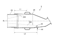
- FIG. 7 is a cross-sectional view schematically showing a flame formed in the cylinder 24 during partial load operation in the combustor 3 according to some embodiments of the present disclosure
- FIG. 8 is a cross-sectional view schematically showing a flame formed in the cylinder 24, and
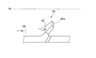
- FIG. 8 is a first diaphragm of FIG. It is an enlarged view which shows the part 40 from the side
- FIG. 9 is a perspective view which shows by extracting the 1st drawing part 40 of FIG. 7 by itself
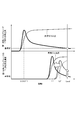
- FIG. 10 is a temperature and carbon monoxide concentration corresponding to FIG. It is a figure which shows the distribution of.
- the combustor 3 has a first throttle portion 40 extending along the circumferential direction so as to correspond to one of the first fuel nozzle group 32A and the second fuel nozzle group 32B.
- the first throttle portion 40 is provided so as to correspond to the second fuel nozzle group 32B in which the fuel supply amount is controlled to be small during the partial load operation.
- the first throttle portion 40 is provided in a range overlapping the arrangement region of each fuel nozzle 22B belonging to the second fuel nozzle group 32B when viewed from the downstream side along the combustor axis Ac. ing.
- at least a part of the combustion gas generated by the combustion of the fuel supplied from each fuel nozzle 22B belonging to the second fuel nozzle group 32B is configured to hit the first throttle portion 40.
- the first throttle portion 40 is provided with respect to the arrangement region of each fuel nozzle 22B belonging to the second fuel nozzle group 32B.
- the range of may be provided with a predetermined phase difference.
- the first drawing portion 40 is formed so as to project inward in the radial direction from the inner peripheral surface of the tubular body 24.
- the first throttle portion 40 is oblique with respect to the combustor axis Ac so as to receive the combustion gas flowing from the upstream side to the downstream side inside the cylinder 24. It has a receiving surface 42 formed on the surface. Since such a combustor 3 has the first throttle portion 40, the combustion gas from the fuel from the fuel nozzle 22B belonging to the second fuel nozzle group 32B is compared in temperature by the receiving surface 42 of the first throttle portion 40. It is deflected inward in the radial direction of the high target cylinder 24.
- the temperature of the combustion gas produced by the fuel from the fuel nozzle 22B belonging to the second fuel nozzle group 32B rises at the position L2 corresponding to the first throttle portion 40.
- the formation range of the second flame 38B is reduced (moved to the upstream side) as compared with the case of the comparative example described above with reference to FIGS. 5 and 6, and the consumption of carbon monoxide contained in the combustion gas is reduced. Be promoted.
- the cylindrical body 24 is reduced.
- the load range that can be operated is expanded while keeping the concentration of carbon monoxide in the downstream end Lend below the standard value, so that the turndown performance (low load operation performance) is improved as compared with the comparative example. Can be done.
- the first diaphragm portion 40 partially extends along the circumferential direction. That is, since the first throttle portion 40 has an asymmetrical configuration, it is possible to suitably suppress combustion vibration that tends to occur during partial load operation.
- the first diaphragm portion 40 may include a plurality of diaphragm pieces 40a arranged at intervals along the circumferential direction. Since the temperature of the first throttle portion 40 rises by receiving the combustion gas flowing inside the cylinder 24, it is supplied as cooling air 44 as a cooling medium (see FIG. 7). Here, since a part of the compressed air supplied from the compressor 2 is used as the cooling air 44, when the cooling air 44 increases, it is used to generate combustion gas by mixing with the fuel from the fuel nozzle 22. The amount of compressed air produced may decrease, and NOx emissions may increase.
- the first throttle portion 40 is divided into a plurality of throttle pieces 40a to reduce the heat capacity of the first throttle portion 40, and the temperature of the first throttle portion 40 is reduced with a small amount of cooling air 44.
- the rise can be suppressed.
- the compressed air used for generating the combustion gas by mixing with the fuel from the fuel nozzle 22 can be sufficiently secured, and the NOx emission amount can be suppressed.
- These plurality of throttle pieces 40a are arranged between adjacent fuel nozzles 22B along the circumferential direction when viewed from the axial direction as shown in FIG. At such a position, the temperature of the combustion gas tends to be lower than that at the position where it overlaps the fuel nozzle 22B. By flowing the gas, the temperature rise of the combustion gas can be effectively promoted.
- these plurality of diaphragm pieces 40a may be integrally configured by being connected to each other by a connecting member 40b extending along the circumferential direction. This facilitates the work of attaching the first throttle portion 40 to the inner peripheral surface of the tubular body 24.
- the plurality of diaphragm pieces 40a constituting the first diaphragm portion 40 may include a grooved diaphragm piece 45 having a groove portion 41.
- FIG. 11 is a diagram showing an example of the first throttle portion 40 including the grooved throttle piece 45
- FIG. 12 is a diagram showing the grooved throttle piece 45 of FIG. 11 from the inside in the radial direction together with the flow of combustion gas.
- FIGS. 11 and 12 the case where the first diaphragm portion 40 is composed of a plurality of diaphragm pieces 40a which are independent members (separate members) is illustrated, but as shown in FIG. 9, a plurality of diaphragm pieces 40a are illustrated.
- the diaphragm pieces 40a may be connected by a connecting member 40b.
- FIG. 11 shows a case where a part of the plurality of diaphragm pieces 40a included in the first diaphragm portion 40 is configured as the grooved diaphragm piece 45, but the grooved diaphragm pieces 45 in the plurality of diaphragm pieces 40a are shown.
- the ratio may be arbitrary.
- all the diaphragm pieces 40a may be the grooved diaphragm pieces 45, or all the diaphragm pieces 45 may be the grooveless diaphragm pieces as in the above-described embodiment.
- the grooved diaphragm piece 45 has a groove portion 41 formed so as to extend radially outward from the radial inner edge portion 43.
- the groove portion 41 extends from the radial inner edge portion 43 to the radial outer edge portion 47, so that the grooved drawing piece 45 is divided into a first piece member 45a and a second piece member 45b. ing.
- the groove 41 may be configured as a recess that is partially cut outward from the radial inner edge 43 (that is, does not reach the radial outer edge 47).
- the grooved diaphragm piece 45 has a configuration in which the first piece member 45a and the second piece member 45b are partially connected.
- a vortex 46 is formed on the downstream side of the grooved throttle piece 45 as shown in FIG.
- the vortex 46 is formed so as to swivel in the in-plane direction in a cross section perpendicular to the axial direction of the tubular body 24. Combustion gas is agitated inside the cylinder 24 by such a vortex 46, and combustion can be promoted.
- the shape and size of the groove 41 can be arbitrarily set, but if the groove 41 is too large, the combustion promotion effect due to the radial deflection of the combustion gas by the first throttle 40 described above is reduced, and the opposite is true. If the groove 41 is too small, the combustion promoting effect of the vortex 46 formed by the groove 41 will be reduced, so it is preferable to consider the balance between them. Further, the size of the groove 41 is preferably sufficiently small with respect to the arrangement interval (pitch) of the plurality of fuel nozzles 22 in the circumferential direction, and is preferably set to, for example, the throttle height or less.
- the groove portion 41 is provided at a substantially center position along the circumferential direction of the grooved diaphragm piece 45. By setting the position of the groove 41 in this way, a vortex 46 for promoting combustion can be effectively generated.
- FIG. 13 is a modification of FIG. 7
- FIG. 14 is a side view of the tubular body 24 which transparently shows the first drawing portion 40 and the second drawing portion 50 of FIG. 13, and
- FIG. 15 is a plurality of views of FIG. It is a schematic view which shows the fuel nozzle 22 from the downstream side along the combustor axis Ac
- FIG. 16 is a figure which shows the distribution of temperature and carbon monoxide concentration corresponding to FIG.
- the combustor 3 further includes a second throttle portion 50 in addition to the above-mentioned first throttle portion 40.
- the second throttle portion 50 is provided so as to extend along the circumferential direction so as to correspond to the other of the first fuel nozzle group 32A and the second fuel nozzle group 32B.
- the first throttle portion 40 is provided corresponding to the second fuel nozzle group 32B
- the second throttle portion 50 is provided corresponding to the first fuel nozzle group 32A. That is, during the partial load operation of the combustor 3, the first throttle unit 40 corresponding to the second fuel nozzle group 32B, in which the fuel injection amount is controlled to be small, becomes the first fuel nozzle group 32A in which the fuel injection amount is controlled to be large. It is provided on the upstream side of the corresponding second throttle portion 50.
- the formation range of the second flame is wide.
- the combustion temperature is also relatively low, carbon monoxide is more likely to be generated as compared with the first fuel nozzle group 32A side. Therefore, by arranging the first throttle portion 40 corresponding to the second fuel nozzle group 32B on the upstream side of the second throttle portion 50 corresponding to the first fuel nozzle group 32A, the inner peripheral surface is located close to the fuel nozzle. Combustion gas in the vicinity can flow toward the center. As a result, the combustion of the combustion gas in the second fuel nozzle group 32B can be further promoted, and the carbon monoxide emitted from the combustion gas can be effectively reduced.
- the second throttle portion 50 has substantially the same shape as the first throttle portion 40 described above with reference to FIG. 8, and is provided so as to project inward in the radial direction from the inner peripheral surface of the tubular body 24. Be done. As a result, the combustion gas in the vicinity of the inner peripheral surface provided with the second throttle portion 50 is flowed toward the inside in the radial direction of the tubular body 24 where the temperature becomes relatively high. As a result, the combustion gas corresponding to the first fuel nozzle group 32A on the other side can also be promoted to burn, and carbon monoxide contained in the combustion gas can be reduced more effectively.
- the combustion gas temperature in the first fuel nozzle group 32A is further increased in the vicinity of the distance L3 where the second throttle portion 50 is provided, and the monoxide concentration contained in the combustion gas is further reduced. It is shown (note that in FIG. 16, the relative positional relationships of the distances L1, L1', L2, L2', and L3 are appropriately changed from other drawings in order to show the illustration in an easy-to-understand manner).
- Such a second drawing portion 50 partially extends along the circumferential direction on the inner peripheral surface of the tubular body 24 like the first drawing portion 40, but as shown in FIGS. 13 and 14, the second drawing portion 50 extends. 1 It has an asymmetrical configuration because it is provided at a position in the axial direction different from that of the diaphragm portion 40. Therefore, even when the second throttle portion 50 is additionally provided in addition to the first throttle portion 40, the combustion vibration during the partial load operation can be effectively suppressed.
- the first throttle portion 40 and the second throttle portion 50 are provided so that the ratio of the distance to the downstream end portion Lend of the tubular body 24 and the oxidation rate of CO contained in the combustion gas is equal.
- the distance L3 from the upstream end of the cylinder 24 to the second throttle 50, and the CO oxidation rate V1 in the fuel nozzle 22A belonging to the first fuel nozzle group 32A corresponding to the second throttle 50 are as follows.
- the second diaphragm portion 50 may include a plurality of diaphragm pieces 50a arranged at intervals along the circumferential direction, similarly to the first diaphragm portion 40.
- the heat capacity of the second throttle portion 50 is reduced, and the temperature rise of the second throttle portion 50 is suppressed with a small amount of cooling air 44. can do.
- the compressed air used for generating the combustion gas can be sufficiently secured by mixing with the fuel from the fuel nozzle 22, and the NOx emission amount can be suppressed.
- These plurality of throttle pieces 50a are arranged between adjacent fuel nozzles 22A along the circumferential direction when viewed from the axial direction as shown in FIG. At such a position, the temperature of the combustion gas tends to be lower than the position where it overlaps the fuel nozzle 22A. Therefore, by flowing the combustion gas inward in the radial direction by the second throttle portion 50, the temperature of the combustion gas is effectively raised. Can be promoted.
- these plurality of diaphragm pieces 50a may also be integrally configured by being connected to each other by a connecting member 50b extending along the circumferential direction. This facilitates the work of attaching the second throttle portion 50 to the inner peripheral surface of the tubular body 24.
- the plurality of diaphragm pieces 50a constituting the second diaphragm portion 50 may include a grooved diaphragm piece 55 having a groove portion 51.
- FIG. 17 is a diagram showing an example of the second throttle portion 50 including the grooved throttle piece 55
- FIG. 18 is a diagram showing the grooved throttle piece 55 of FIG. 17 from the inside in the radial direction together with the flow of combustion gas.
- FIGS. 17 and 18 the case where the second diaphragm portion 50 is composed of a plurality of diaphragm pieces 50a which are independent members (separate members) is illustrated, but as shown in FIG. 15, a plurality of diaphragm pieces 50a are illustrated.
- the diaphragm piece 50a may be connected by a connecting member 50b.
- FIG. 17 shows a case where a part of the plurality of diaphragm pieces 50a included in the second diaphragm portion 50 is configured as the grooved diaphragm piece 55, but the grooved diaphragm pieces 55 in the plurality of diaphragm pieces 50a are shown.
- the ratio may be arbitrary.
- all the diaphragm pieces 50a may be the grooved diaphragm pieces 55, or all the diaphragm pieces 55 may be the grooveless diaphragm pieces as in the above-described embodiment.
- the grooved diaphragm piece 55 has a groove portion 51 formed so as to extend radially outward from the radial inner edge portion 53.
- the groove portion 51 extends from the radial inner edge portion 53 to the radial outer edge portion 57, so that the grooved drawing piece 55 is divided into a first piece member 55a and a second piece member 55b. ing.
- the groove 51 may be configured as a recess that is partially cut outward from the radial inner edge 53 (that is, does not reach the radial outer edge 57).
- the grooved diaphragm piece 55 has a configuration in which the first piece member 55a and the second piece member 55b are partially connected.
- a vortex 56 is formed on the downstream side of the grooved throttle piece 55 as shown in FIG.
- the vortex 56 is formed so as to swivel in the in-plane direction in a cross section perpendicular to the axial direction of the tubular body 24. Combustion gas is agitated inside the cylinder 24 by such a vortex 56, and combustion can be promoted.
- the shape and size of the groove 51 can be arbitrarily set, but if the groove 51 is too large, the combustion promotion effect due to the radial deflection of the combustion gas by the second throttle 50 described above is reduced, and the opposite is true. If the groove 51 is too small, the combustion promoting effect of the vortex 56 formed by the groove 51 will be reduced, so the determination should be made in consideration of these balances. Further, the size of the groove 51 is preferably sufficiently small with respect to the arrangement interval (pitch) of the plurality of fuel nozzles 22 in the circumferential direction, and is preferably set to, for example, the throttle height or less.
- the groove portion 51 is provided at a substantially center position along the circumferential direction of the grooved diaphragm piece 55. By setting the position of the groove 51 in this way, a vortex 56 for promoting combustion can be effectively generated.
- the combustor 3 of the gas turbine 1 capable of suitably suppressing the generation of carbon monoxide while preventing combustion vibration during partial load operation.
- the combustor of the gas turbine is The first fuel nozzle group and the second fuel nozzle group, which include fuel nozzles capable of supplying fuel and have fuel supply systems that can be controlled independently of each other.
- the combustion gas in the vicinity of the inner peripheral surface provided with the first throttle portion is deflected inward in the radial direction of the cylinder having a relatively high temperature to promote combustion, and carbon monoxide is effective. Is reduced.
- the first throttle portion has an asymmetrical structure that partially extends along the circumferential direction, combustion vibration is unlikely to occur even during partial load operation. In this way, it is possible to realize a gas turbine combustor capable of suitably suppressing the generation of carbon monoxide while preventing combustion vibration during partial load operation.
- the first diaphragm portion includes a plurality of diaphragm pieces arranged at intervals along the circumferential direction.
- the first diaphragm portion is configured to include a plurality of diaphragm pieces.
- the first throttle portion may be supplied with cooling air in order to suppress a temperature rise due to the amount of heat received from the combustion gas.
- the heat capacity of the first throttle portion can be reduced, and the temperature rise can be effectively suppressed with a small amount of cooling air.
- the plurality of throttle pieces are arranged between the fuel nozzles adjacent to each other along the circumferential direction when viewed from the axial direction.
- the plurality of throttle pieces constituting the first throttle portion are arranged between adjacent fuel nozzles along the circumferential direction when viewed from the axial direction. Since such a position has a relatively low temperature as compared with the position where it overlaps the fuel nozzle, it is effective in suppressing the temperature rise in the first throttle portion.
- the plurality of diaphragm pieces constituting the first diaphragm portion are integrally formed by being connected to each other by connecting members extending along the circumferential direction. This facilitates the work of attaching the first throttle portion to the inner peripheral surface of the cylinder.
- the plurality of diaphragm pieces include a grooved diaphragm piece having a groove portion formed from the radial inner edge portion of the diaphragm piece toward the radial outer side.
- At least a part of the plurality of diaphragm pieces included in the first diaphragm member is configured as a grooved diaphragm piece.
- the grooved diaphragm piece has a groove portion formed from the radial inner edge portion to the radial outer side. The groove can effectively promote combustion by forming a vortex on the downstream side of the drawing piece when the combustion gas received by the drawing piece passes through.
- the grooved diaphragm piece includes a first piece member and a second piece member that are separated from each other by the groove portion.
- the grooved diaphragm piece has a structure in which the first piece member and the second piece member are separated from each other by a groove portion.
- the groove portion is provided at a substantially center position along the circumferential direction of the grooved diaphragm piece.
- a vortex for promoting combustion is effectively generated by providing the groove portion at a substantially center position along the circumferential direction of the grooved diaphragm piece. Can be done.
- a second fuel nozzle group that partially extends along the circumferential direction so as to correspond to the other of the first fuel nozzle group and the second fuel nozzle group, and protrudes inward in the radial direction from the inner peripheral surface of the cylinder.
- the first throttle portion and the second throttle portion are provided at different axial positions from each other.
- a second throttle portion corresponding to the other of the first fuel nozzle group and the second fuel nozzle group is provided. Similar to the first throttle portion, the second throttle portion is configured to project inward in the radial direction, so that the combustion gas is provided in the vicinity of the inner peripheral surface of the cylinder provided with the second throttle portion. Is deflected inward in the radial direction. As a result, the combustion of the combustion gas is promoted on the other side as well, and carbon monoxide can be effectively reduced. Further, the second throttle portion has an asymmetrical configuration that partially extends along the circumferential direction at positions in the axial direction different from those of the first throttle portion. Therefore, even when the second throttle portion is additionally provided in addition to the first throttle portion, the combustion vibration during the partial load operation can be effectively suppressed.
- the second diaphragm portion includes a plurality of diaphragm pieces arranged at intervals along the circumferential direction.
- the second diaphragm portion is configured to include a plurality of diaphragm pieces. Similar to the first throttle portion described above, the second throttle portion may be supplied with cooling air in order to suppress a temperature rise due to receiving the combustion gas flowing inside the cylinder. In this embodiment, by dividing the second throttle portion into a plurality of throttle pieces, the heat capacity of the second throttle portion can be reduced, and the temperature rise can be effectively suppressed with a small amount of cooling air.
- the plurality of throttle pieces are arranged between adjacent fuel nozzles along the circumferential direction when viewed from the axial direction.
- the plurality of throttle pieces constituting the second throttle portion also have fuel nozzles adjacent to each other along the circumferential direction when viewed from the axial direction, similarly to the first throttle portion described above. Placed in between. Since such a position has a relatively low temperature as compared with the position where it overlaps the fuel nozzle, it is effective in suppressing the temperature rise in the second throttle portion.
- the plurality of diaphragm pieces constituting the second diaphragm portion are also connected to each other by a connecting member extending along the circumferential direction, similarly to the first diaphragm portion described above. It is integrally composed of. This facilitates the work of attaching the second throttle portion to the inner peripheral surface of the cylinder.
- the plurality of diaphragm pieces include a grooved diaphragm piece having a groove portion formed from the radial inner edge portion of the diaphragm piece toward the radial outer side.
- At least a part of the plurality of diaphragm pieces included in the second diaphragm member is configured as a grooved diaphragm piece.
- the grooved diaphragm piece has a groove portion formed from the radial inner edge portion to the radial outer side. The groove can effectively promote combustion by forming a vortex on the downstream side of the drawing piece when the combustion gas received by the drawing piece passes through.
- the grooved diaphragm piece includes a first piece member and a second piece member that are separated from each other by the groove portion.
- the grooved diaphragm piece has a structure in which the first piece member and the second piece member are separated from each other by a groove portion.
- the groove portion is provided at a substantially center position along the circumferential direction of the grooved diaphragm piece.
- a vortex for promoting combustion is effectively generated by providing the groove portion at a substantially center position along the circumferential direction of the grooved diaphragm piece. Can be done.
- the fuel nozzle included in the first fuel nozzle group is controlled to have a larger fuel injection amount than the fuel nozzle included in the second fuel nozzle group during partial load operation.
- the first throttle portion is provided so as to correspond to the second fuel nozzle group.
- the second throttle portion is provided so as to correspond to the first fuel nozzle group.
- the first throttle portion is provided on the upstream side of the second throttle portion.
- the first throttle portion corresponding to the second fuel nozzle group is provided on the upstream side of the second throttle portion corresponding to the first fuel nozzle group. Since the fuel nozzle belonging to the second fuel nozzle group has a smaller fuel injection amount than the fuel nozzle belonging to the first fuel nozzle group, the flame formation range is wide and the combustion temperature is relatively low, so that the first fuel Compared to combustion nozzles belonging to the nozzle group, carbon monoxide is more likely to be generated. Therefore, by arranging the first throttle portion corresponding to the second fuel nozzle group on the upstream side of the second throttle portion corresponding to the first fuel nozzle group, the combustion gas near the inner peripheral surface at a position close to the fuel nozzle. Can be deflected toward the center to promote combustion and reduce carbon monoxide.
- the first throttle portion and the second throttle portion are provided so that the ratio of the distance from the upstream end portion of the cylinder body to the oxidation rate of CO contained in the combustion gas is equal.
- the gas turbine according to one aspect includes the combustor according to any one of the above (1) to (16).
- the combustor having the above configuration, it is possible to realize a gas turbine capable of suitably suppressing the generation of carbon monoxide while preventing combustion vibration during partial load operation.
Landscapes
- Engineering & Computer Science (AREA)
- Chemical & Material Sciences (AREA)
- Combustion & Propulsion (AREA)
- Mechanical Engineering (AREA)
- General Engineering & Computer Science (AREA)
Priority Applications (5)
| Application Number | Priority Date | Filing Date | Title |
|---|---|---|---|
| US17/914,694 US20240027069A1 (en) | 2020-03-31 | 2021-03-31 | Combustor for gas turbine and gas turbine |
| DE112021002128.1T DE112021002128T5 (de) | 2020-03-31 | 2021-03-31 | Brennkammer für Gasturbine und Gasturbine |
| JP2022512616A JP7386325B2 (ja) | 2020-03-31 | 2021-03-31 | ガスタービンの燃焼器、及び、ガスタービン |
| KR1020227029765A KR102693689B1 (ko) | 2020-03-31 | 2021-03-31 | 가스 터빈의 연소기 및 가스 터빈 |
| CN202180024645.7A CN115335638A (zh) | 2020-03-31 | 2021-03-31 | 燃气轮机的燃烧器以及燃气轮机 |
Applications Claiming Priority (2)
| Application Number | Priority Date | Filing Date | Title |
|---|---|---|---|
| JP2020-063062 | 2020-03-31 | ||
| JP2020063062 | 2020-03-31 |
Publications (1)
| Publication Number | Publication Date |
|---|---|
| WO2021201093A1 true WO2021201093A1 (ja) | 2021-10-07 |
Family
ID=77928561
Family Applications (1)
| Application Number | Title | Priority Date | Filing Date |
|---|---|---|---|
| PCT/JP2021/013809 Ceased WO2021201093A1 (ja) | 2020-03-31 | 2021-03-31 | ガスタービンの燃焼器、及び、ガスタービン |
Country Status (6)
| Country | Link |
|---|---|
| US (1) | US20240027069A1 (https=) |
| JP (1) | JP7386325B2 (https=) |
| KR (1) | KR102693689B1 (https=) |
| CN (1) | CN115335638A (https=) |
| DE (1) | DE112021002128T5 (https=) |
| WO (1) | WO2021201093A1 (https=) |
Cited By (2)
| Publication number | Priority date | Publication date | Assignee | Title |
|---|---|---|---|---|
| JPWO2023176570A1 (https=) * | 2022-03-14 | 2023-09-21 | ||
| KR20240146042A (ko) | 2022-03-11 | 2024-10-07 | 미츠비시 파워 가부시키가이샤 | 결합체 및 이 결합체를 제조하는 방법 및 연소기 및 이 연소기를 제조하는 방법 |
Citations (2)
| Publication number | Priority date | Publication date | Assignee | Title |
|---|---|---|---|---|
| JP2011102669A (ja) * | 2009-11-10 | 2011-05-26 | Mitsubishi Heavy Ind Ltd | ガスタービン燃焼器及びガスタービン |
| JP2019020071A (ja) * | 2017-07-19 | 2019-02-07 | 三菱重工業株式会社 | 燃焼器及びガスタービン |
Family Cites Families (15)
| Publication number | Priority date | Publication date | Assignee | Title |
|---|---|---|---|---|
| US4356698A (en) * | 1980-10-02 | 1982-11-02 | United Technologies Corporation | Staged combustor having aerodynamically separated combustion zones |
| US4490156A (en) * | 1981-06-10 | 1984-12-25 | Texaco Inc. | Partial oxidation system |
| JPH11166707A (ja) * | 1997-12-04 | 1999-06-22 | Sanyo Electric Co Ltd | ロータリーバーナ |
| JP2001041418A (ja) * | 1999-07-27 | 2001-02-13 | Noritz Corp | バーナ |
| DE10049205A1 (de) * | 2000-10-05 | 2002-05-23 | Alstom Switzerland Ltd | Verfahren und Vorrichtung zur Brennstoffversorgung eines Vormischbrenners |
| JP4096056B2 (ja) * | 2003-06-02 | 2008-06-04 | 独立行政法人 宇宙航空研究開発機構 | ガスタービン用燃料ノズル |
| JP2005076982A (ja) * | 2003-08-29 | 2005-03-24 | Mitsubishi Heavy Ind Ltd | ガスタービン燃焼器 |
| JP4274996B2 (ja) * | 2004-04-27 | 2009-06-10 | 三菱重工業株式会社 | ガスタービン燃焼器 |
| JP2006029677A (ja) * | 2004-07-15 | 2006-02-02 | Hitachi Ltd | 複数のバーナを備えた燃焼器 |
| JP5804808B2 (ja) * | 2011-07-07 | 2015-11-04 | 三菱日立パワーシステムズ株式会社 | ガスタービン燃焼器及びその燃焼振動減衰方法 |
| US20130139486A1 (en) * | 2011-12-01 | 2013-06-06 | General Electric Company | Variable initiation location system for pulse detonation combustor |
| JP5743122B2 (ja) * | 2012-02-28 | 2015-07-01 | 三菱日立パワーシステムズ株式会社 | 燃焼器及びガスタービン |
| JP6623485B2 (ja) * | 2014-09-25 | 2019-12-25 | 三菱日立パワーシステムズ株式会社 | 燃焼器、及びこれを備えるガスタービン |
| JP6508470B2 (ja) | 2015-07-31 | 2019-05-08 | 三菱日立パワーシステムズ株式会社 | 燃料流量設定方法、この方法を実行する装置、この装置を備えるガスタービンプラント |
| JP6843513B2 (ja) * | 2016-03-29 | 2021-03-17 | 三菱パワー株式会社 | 燃焼器、燃焼器の性能向上方法 |
-
2021
- 2021-03-31 US US17/914,694 patent/US20240027069A1/en not_active Abandoned
- 2021-03-31 WO PCT/JP2021/013809 patent/WO2021201093A1/ja not_active Ceased
- 2021-03-31 KR KR1020227029765A patent/KR102693689B1/ko active Active
- 2021-03-31 CN CN202180024645.7A patent/CN115335638A/zh active Pending
- 2021-03-31 JP JP2022512616A patent/JP7386325B2/ja active Active
- 2021-03-31 DE DE112021002128.1T patent/DE112021002128T5/de active Pending
Patent Citations (2)
| Publication number | Priority date | Publication date | Assignee | Title |
|---|---|---|---|---|
| JP2011102669A (ja) * | 2009-11-10 | 2011-05-26 | Mitsubishi Heavy Ind Ltd | ガスタービン燃焼器及びガスタービン |
| JP2019020071A (ja) * | 2017-07-19 | 2019-02-07 | 三菱重工業株式会社 | 燃焼器及びガスタービン |
Cited By (5)
| Publication number | Priority date | Publication date | Assignee | Title |
|---|---|---|---|---|
| KR20240146042A (ko) | 2022-03-11 | 2024-10-07 | 미츠비시 파워 가부시키가이샤 | 결합체 및 이 결합체를 제조하는 방법 및 연소기 및 이 연소기를 제조하는 방법 |
| US12460817B2 (en) | 2022-03-11 | 2025-11-04 | Mitsubishi Heavy Industries, Ltd. | Assembly, method for manufacturing assembly, burner, and method for manufacturing burner |
| JPWO2023176570A1 (https=) * | 2022-03-14 | 2023-09-21 | ||
| WO2023176570A1 (ja) * | 2022-03-14 | 2023-09-21 | 三菱重工業株式会社 | ガスタービン燃焼器及びガスタービン |
| JP7736911B2 (ja) | 2022-03-14 | 2025-09-09 | 三菱重工業株式会社 | ガスタービン燃焼器及びガスタービン |
Also Published As
| Publication number | Publication date |
|---|---|
| CN115335638A (zh) | 2022-11-11 |
| US20240027069A1 (en) | 2024-01-25 |
| DE112021002128T5 (de) | 2023-03-09 |
| JPWO2021201093A1 (https=) | 2021-10-07 |
| KR20220160546A (ko) | 2022-12-06 |
| JP7386325B2 (ja) | 2023-11-24 |
| KR102693689B1 (ko) | 2024-08-08 |
Similar Documents
| Publication | Publication Date | Title |
|---|---|---|
| CN102378878B (zh) | 旋流器、燃烧腔以及具有改善的涡流的燃气涡轮机 | |
| JP6805355B2 (ja) | 燃料/空気の混合が改良されたスワーラ、燃焼器アセンブリおよびガスタービン | |
| EP3303929B1 (en) | Combustor arrangement | |
| JP5947515B2 (ja) | 渦発生装置を有する混合管要素を備えたターボ機械 | |
| JP2010276334A (ja) | タービンにおける空気及び燃料の噴射方法及び装置 | |
| CN102434232B (zh) | 涡轮排气仓室 | |
| GB2593123A (en) | Combustor for a gas turbine | |
| JP2002039533A (ja) | 燃焼器、ガスタービン及びジェットエンジン | |
| JP2013231582A (ja) | タービンエンジン用の燃料/空気予混合システム | |
| WO2006132153A1 (ja) | ガスタービンの予混合燃焼バーナー | |
| JP2011007479A (ja) | ガスタービンエンジン内のベーンスワール角を低減させる方法及びシステム | |
| JP2007155325A (ja) | スワーラ組立体及びスワーラを作動させる方法 | |
| US20250179960A1 (en) | Burner assembly, gas turbine combustor, and gas turbine | |
| JP2020118391A (ja) | ガスタービン燃焼器及びガスタービン | |
| GB2585025A (en) | Combustor for a gas turbine | |
| US10982544B2 (en) | Turbine and gas turbine | |
| WO2021201093A1 (ja) | ガスタービンの燃焼器、及び、ガスタービン | |
| CN115989383A (zh) | 用于燃气涡轮机的燃烧器 | |
| CN107850308B (zh) | 用于燃气轮机的燃烧器 | |
| US20200200389A1 (en) | Gas Turbine Combustor, Manufacturing Method for Gas Turbine and Gas Turbine Combustor | |
| US20170051919A1 (en) | Swirler for a burner of a gas turbine engine, burner of a gas turbine engine and gas turbine engine | |
| CN116464988A (zh) | 径向-径向-轴向旋流器组件 | |
| JP6345331B1 (ja) | ガスタービンの燃焼筒及び燃焼器並びにガスタービン | |
| JP6840229B2 (ja) | ガスタービンエンジン燃焼器用の中央パイロット燃料噴射を備えるパイロットバーナアセンブリ | |
| CN102692036A (zh) | 具有带有人字形肋的燃料喷嘴衬套的燃烧器 |
Legal Events
| Date | Code | Title | Description |
|---|---|---|---|
| 121 | Ep: the epo has been informed by wipo that ep was designated in this application |
Ref document number: 21780700 Country of ref document: EP Kind code of ref document: A1 |
|
| ENP | Entry into the national phase |
Ref document number: 2022512616 Country of ref document: JP Kind code of ref document: A |
|
| WWE | Wipo information: entry into national phase |
Ref document number: 17914694 Country of ref document: US |
|
| 122 | Ep: pct application non-entry in european phase |
Ref document number: 21780700 Country of ref document: EP Kind code of ref document: A1 |