WO2021200012A1 - レンズ駆動装置、カメラモジュールおよびカメラ搭載装置 - Google Patents
レンズ駆動装置、カメラモジュールおよびカメラ搭載装置 Download PDFInfo
- Publication number
- WO2021200012A1 WO2021200012A1 PCT/JP2021/009773 JP2021009773W WO2021200012A1 WO 2021200012 A1 WO2021200012 A1 WO 2021200012A1 JP 2021009773 W JP2021009773 W JP 2021009773W WO 2021200012 A1 WO2021200012 A1 WO 2021200012A1
- Authority
- WO
- WIPO (PCT)
- Prior art keywords
- unit
- optical axis
- lens
- pole
- movable
- Prior art date
- Legal status (The legal status is an assumption and is not a legal conclusion. Google has not performed a legal analysis and makes no representation as to the accuracy of the status listed.)
- Ceased
Links
Images








Classifications
-
- G—PHYSICS
- G02—OPTICS
- G02B—OPTICAL ELEMENTS, SYSTEMS OR APPARATUS
- G02B13/00—Optical objectives specially designed for the purposes specified below
- G02B13/001—Miniaturised objectives for electronic devices, e.g. portable telephones, webcams, PDAs, small digital cameras
- G02B13/0055—Miniaturised objectives for electronic devices, e.g. portable telephones, webcams, PDAs, small digital cameras employing a special optical element
- G02B13/0065—Miniaturised objectives for electronic devices, e.g. portable telephones, webcams, PDAs, small digital cameras employing a special optical element having a beam-folding prism or mirror
-
- G—PHYSICS
- G03—PHOTOGRAPHY; CINEMATOGRAPHY; ANALOGOUS TECHNIQUES USING WAVES OTHER THAN OPTICAL WAVES; ELECTROGRAPHY; HOLOGRAPHY
- G03B—APPARATUS OR ARRANGEMENTS FOR TAKING PHOTOGRAPHS OR FOR PROJECTING OR VIEWING THEM; APPARATUS OR ARRANGEMENTS EMPLOYING ANALOGOUS TECHNIQUES USING WAVES OTHER THAN OPTICAL WAVES; ACCESSORIES THEREFOR
- G03B5/00—Adjustment of optical system relative to image or object surface other than for focusing
- G03B5/04—Vertical adjustment of lens; Rising fronts
-
- G—PHYSICS
- G02—OPTICS
- G02B—OPTICAL ELEMENTS, SYSTEMS OR APPARATUS
- G02B7/00—Mountings, adjusting means, or light-tight connections, for optical elements
- G02B7/02—Mountings, adjusting means, or light-tight connections, for optical elements for lenses
- G02B7/04—Mountings, adjusting means, or light-tight connections, for optical elements for lenses with mechanism for focusing or varying magnification
- G02B7/10—Mountings, adjusting means, or light-tight connections, for optical elements for lenses with mechanism for focusing or varying magnification by relative axial movement of several lenses, e.g. of varifocal objective lens
- G02B7/102—Mountings, adjusting means, or light-tight connections, for optical elements for lenses with mechanism for focusing or varying magnification by relative axial movement of several lenses, e.g. of varifocal objective lens controlled by a microcomputer
-
- B—PERFORMING OPERATIONS; TRANSPORTING
- B06—GENERATING OR TRANSMITTING MECHANICAL VIBRATIONS IN GENERAL
- B06B—METHODS OR APPARATUS FOR GENERATING OR TRANSMITTING MECHANICAL VIBRATIONS OF INFRASONIC, SONIC, OR ULTRASONIC FREQUENCY, e.g. FOR PERFORMING MECHANICAL WORK IN GENERAL
- B06B1/00—Methods or apparatus for generating mechanical vibrations of infrasonic, sonic, or ultrasonic frequency
- B06B1/02—Methods or apparatus for generating mechanical vibrations of infrasonic, sonic, or ultrasonic frequency making use of electrical energy
- B06B1/06—Methods or apparatus for generating mechanical vibrations of infrasonic, sonic, or ultrasonic frequency making use of electrical energy operating with piezoelectric effect or with electrostriction
-
- G—PHYSICS
- G02—OPTICS
- G02B—OPTICAL ELEMENTS, SYSTEMS OR APPARATUS
- G02B13/00—Optical objectives specially designed for the purposes specified below
- G02B13/001—Miniaturised objectives for electronic devices, e.g. portable telephones, webcams, PDAs, small digital cameras
- G02B13/009—Miniaturised objectives for electronic devices, e.g. portable telephones, webcams, PDAs, small digital cameras having zoom function
-
- G—PHYSICS
- G02—OPTICS
- G02B—OPTICAL ELEMENTS, SYSTEMS OR APPARATUS
- G02B7/00—Mountings, adjusting means, or light-tight connections, for optical elements
- G02B7/02—Mountings, adjusting means, or light-tight connections, for optical elements for lenses
- G02B7/04—Mountings, adjusting means, or light-tight connections, for optical elements for lenses with mechanism for focusing or varying magnification
- G02B7/08—Mountings, adjusting means, or light-tight connections, for optical elements for lenses with mechanism for focusing or varying magnification adapted to co-operate with a remote control mechanism
-
- G—PHYSICS
- G02—OPTICS
- G02B—OPTICAL ELEMENTS, SYSTEMS OR APPARATUS
- G02B7/00—Mountings, adjusting means, or light-tight connections, for optical elements
- G02B7/02—Mountings, adjusting means, or light-tight connections, for optical elements for lenses
- G02B7/04—Mountings, adjusting means, or light-tight connections, for optical elements for lenses with mechanism for focusing or varying magnification
- G02B7/09—Mountings, adjusting means, or light-tight connections, for optical elements for lenses with mechanism for focusing or varying magnification adapted for automatic focusing or varying magnification
-
- G—PHYSICS
- G03—PHOTOGRAPHY; CINEMATOGRAPHY; ANALOGOUS TECHNIQUES USING WAVES OTHER THAN OPTICAL WAVES; ELECTROGRAPHY; HOLOGRAPHY
- G03B—APPARATUS OR ARRANGEMENTS FOR TAKING PHOTOGRAPHS OR FOR PROJECTING OR VIEWING THEM; APPARATUS OR ARRANGEMENTS EMPLOYING ANALOGOUS TECHNIQUES USING WAVES OTHER THAN OPTICAL WAVES; ACCESSORIES THEREFOR
- G03B17/00—Details of cameras or camera bodies; Accessories therefor
- G03B17/02—Bodies
- G03B17/12—Bodies with means for supporting objectives, supplementary lenses, filters, masks, or turrets
-
- G—PHYSICS
- G03—PHOTOGRAPHY; CINEMATOGRAPHY; ANALOGOUS TECHNIQUES USING WAVES OTHER THAN OPTICAL WAVES; ELECTROGRAPHY; HOLOGRAPHY
- G03B—APPARATUS OR ARRANGEMENTS FOR TAKING PHOTOGRAPHS OR FOR PROJECTING OR VIEWING THEM; APPARATUS OR ARRANGEMENTS EMPLOYING ANALOGOUS TECHNIQUES USING WAVES OTHER THAN OPTICAL WAVES; ACCESSORIES THEREFOR
- G03B17/00—Details of cameras or camera bodies; Accessories therefor
- G03B17/02—Bodies
- G03B17/17—Bodies with reflectors arranged in beam forming the photographic image, e.g. for reducing dimensions of camera
-
- H—ELECTRICITY
- H02—GENERATION; CONVERSION OR DISTRIBUTION OF ELECTRIC POWER
- H02K—DYNAMO-ELECTRIC MACHINES
- H02K11/00—Structural association of dynamo-electric machines with electric components or with devices for shielding, monitoring or protection
- H02K11/20—Structural association of dynamo-electric machines with electric components or with devices for shielding, monitoring or protection for measuring, monitoring, testing, protecting or switching
- H02K11/21—Devices for sensing speed or position, or actuated thereby
- H02K11/215—Magnetic effect devices, e.g. Hall-effect or magneto-resistive elements
-
- H—ELECTRICITY
- H02—GENERATION; CONVERSION OR DISTRIBUTION OF ELECTRIC POWER
- H02K—DYNAMO-ELECTRIC MACHINES
- H02K41/00—Propulsion systems in which a rigid body is moved along a path due to dynamo-electric interaction between the body and a magnetic field travelling along the path
- H02K41/02—Linear motors; Sectional motors
- H02K41/035—DC motors; Unipolar motors
- H02K41/0352—Unipolar motors
- H02K41/0354—Lorentz force motors, e.g. voice coil motors
- H02K41/0356—Lorentz force motors, e.g. voice coil motors moving along a straight path
-
- G—PHYSICS
- G03—PHOTOGRAPHY; CINEMATOGRAPHY; ANALOGOUS TECHNIQUES USING WAVES OTHER THAN OPTICAL WAVES; ELECTROGRAPHY; HOLOGRAPHY
- G03B—APPARATUS OR ARRANGEMENTS FOR TAKING PHOTOGRAPHS OR FOR PROJECTING OR VIEWING THEM; APPARATUS OR ARRANGEMENTS EMPLOYING ANALOGOUS TECHNIQUES USING WAVES OTHER THAN OPTICAL WAVES; ACCESSORIES THEREFOR
- G03B2205/00—Adjustment of optical system relative to image or object surface other than for focusing
- G03B2205/0007—Movement of one or more optical elements for control of motion blur
- G03B2205/0023—Movement of one or more optical elements for control of motion blur by tilting or inclining one or more optical elements with respect to the optical axis
-
- G—PHYSICS
- G03—PHOTOGRAPHY; CINEMATOGRAPHY; ANALOGOUS TECHNIQUES USING WAVES OTHER THAN OPTICAL WAVES; ELECTROGRAPHY; HOLOGRAPHY
- G03B—APPARATUS OR ARRANGEMENTS FOR TAKING PHOTOGRAPHS OR FOR PROJECTING OR VIEWING THEM; APPARATUS OR ARRANGEMENTS EMPLOYING ANALOGOUS TECHNIQUES USING WAVES OTHER THAN OPTICAL WAVES; ACCESSORIES THEREFOR
- G03B2205/00—Adjustment of optical system relative to image or object surface other than for focusing
- G03B2205/0053—Driving means for the movement of one or more optical element
- G03B2205/0061—Driving means for the movement of one or more optical element using piezoelectric actuators
-
- G—PHYSICS
- G03—PHOTOGRAPHY; CINEMATOGRAPHY; ANALOGOUS TECHNIQUES USING WAVES OTHER THAN OPTICAL WAVES; ELECTROGRAPHY; HOLOGRAPHY
- G03B—APPARATUS OR ARRANGEMENTS FOR TAKING PHOTOGRAPHS OR FOR PROJECTING OR VIEWING THEM; APPARATUS OR ARRANGEMENTS EMPLOYING ANALOGOUS TECHNIQUES USING WAVES OTHER THAN OPTICAL WAVES; ACCESSORIES THEREFOR
- G03B2205/00—Adjustment of optical system relative to image or object surface other than for focusing
- G03B2205/0053—Driving means for the movement of one or more optical element
- G03B2205/0069—Driving means for the movement of one or more optical element using electromagnetic actuators, e.g. voice coils
Definitions
- the present invention relates to a lens driving device, a camera module, and a camera mounting device.
- a camera module mounted on a thin camera-mounted device such as a smartphone is known.
- a camera module is known to include a lens driving device having a zoom function for enlarging or reducing a subject image.
- Patent Document 1 describes a fixed lens in which light from a subject is incident, two movable lenses in which light bent by the fixed lens is incident, and a lens drive that moves the two movable lenses in the direction of the optical axis.
- a configuration including a part is disclosed.
- a magnet portion is provided in the movable portion provided with the movable lens, and a position detecting portion (for example, a hole) for detecting the magnetic flux of the magnet portion. Element) and.
- a position detecting portion for example, a hole
- the magnet portion for example, two different poles (N pole and S pole) are arranged adjacent to each other, and the magnetic force at the portion facing the position detection portion is arranged so as to change according to the position of the movable lens.
- An object of the present invention is to provide a lens driving device, a camera module, and a camera mounting device capable of accurately detecting the position of a movable lens.
- the lens driving device is A movable part that is arranged in the direction of the optical axis and can hold a movable lens,
- a drive unit that drives the movable unit in the direction of the optical axis,
- a magnet portion provided on the movable portion, extending in the direction of the optical axis, and having a first pole and a second pole adjacent to each other across a boundary in a width direction orthogonal to the direction of the optical axis.
- a position detection unit that is arranged to face the magnet unit and detects the position of the magnet unit by detecting a magnetic field on a surface including the direction of the optical axis and the width direction. With The boundary bends and extends so that the angle formed with the direction of the optical axis changes.
- the camera module according to the present invention With the above lens drive A lens portion including the movable lens held by the movable portion and An imaging unit that captures a subject image imaged by the lens unit, and an imaging unit. With The movable lens is driven in the direction of the optical axis.
- the camera-mounted device A camera-mounted device that is an information device or a transportation device.
- An image pickup control unit that processes the image information obtained by the camera module, and To be equipped.
- the position of the movable lens can be accurately detected.
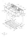
- FIG. 1 It is a figure which shows the camera module which concerns on embodiment of this invention simply. It is a figure which shows simply the structure which looked at the side view of the camera module which concerns on this embodiment. It is a perspective view which shows the housing part of a camera module. It is a perspective view of the bottom wall part side in the housing part of a camera module. It is an exploded perspective view of a housing and a lens part. It is an exploded perspective view of the side wall portion and the bottom wall portion in the housing. It is the figure which looked at the housing from the Z direction + side. It is the figure which looked at the inside of the housing from the negative side in the X direction. It is a figure which shows the guided part. It is a figure which shows the connection part of a lens part and a frame.
- FIG. 1 is a diagram simply showing a camera module 1 according to an embodiment of the present invention.
- FIG. 2 is a diagram simply showing a configuration in which the camera module 1 according to the present embodiment is viewed from the side.
- the camera module 1 is mounted on a thin camera-mounted device such as a smartphone M (see FIGS. 28A and 28B), a mobile phone, a digital camera, a notebook computer, a tablet terminal, a portable game machine, and an in-vehicle camera.
- a smartphone M see FIGS. 28A and 28B
- a mobile phone such as a smartphone M (see FIGS. 28A and 28B), a mobile phone, a digital camera, a notebook computer, a tablet terminal, a portable game machine, and an in-vehicle camera.
- a Cartesian coordinate system (X, Y, Z) is used. Also in the figure described later, it is shown by a common Cartesian coordinate system (X, Y, Z).
- the camera module 1 is mounted so that, for example, the X direction is the left-right direction, the Y direction is the up-down direction, and the Z direction is the front-back direction when shooting is actually performed by the camera-mounted device.
- the light from the subject is incident from the-side (minus side) in the Z direction, bends, and is guided to the + side (plus side) in the Y direction.
- the camera module 1 includes a housing 10, a reflection drive unit 20, a lens unit 30, an image pickup unit 40, a support shaft 50 (see FIG. 3), and a lens drive unit 60 (FIG. 5). (See), a position detection unit 70 (see FIG. 10), and a drive control unit 100.
- the drive control unit 100 includes a CPU (Central Processing Unit), a ROM (Read Only Memory), a RAM (Random Access Memory), and the like.
- the CPU reads a program according to the processing content from the ROM, develops it in the RAM, and centrally controls the lens driving unit 60 in cooperation with the expanded program.
- the drive control unit 100 drives the second lens unit 32 and the third lens unit 33, which will be described later, of the lens unit 30 housed in the housing 10 in the Y direction (direction of the optical axis).
- the camera module 1 performs stepless optical zoom and autofocus.
- the housing 10, the support shaft 50, the lens drive unit 60, the position detection unit 70, and the drive control unit 100 correspond to the "lens drive device" of the present invention.
- the reflection drive unit 20 includes a reflection housing 21, a mirror 22, and a reflection drive control unit 23.
- the reflective housing 21 is arranged adjacent to the negative end of the housing 10 in the Y direction.
- the mirror 22 is provided in the reflective housing 21, and reflects the incident light L1 as the reflected light L2 toward the housing 10.
- the reflection drive control unit 23 includes a CPU, ROM, RAM, and the like, and controls the orientation of the mirror 22.
- the mirror 22 has two rotation axes (not shown) extending in the X direction and the Y direction.
- the mirror 22 rotates around the rotation axis under the control of the reflection drive control unit 23.
- the camera module 1 has a shake correction function (OIS (Optical Image Stabilization) function) that optically corrects shake (vibration) that occurs during shooting to reduce image distortion.
- OIS Optical Image Stabilization
- the reflected light L2 incident on the housing 10 is output to the imaging unit 40 via the lens unit 30 housed in the housing 10.
- the image pickup unit 40 is arranged on the outer surface of the housing 10 on the + side in the Y direction (arrangement portion 112B of the second wall 112 described later), and is configured such that the reflected light L2 is incident through the lens portion 30. Has been done.
- the image pickup unit 40 includes an image pickup device, a substrate, and the like (not shown).
- the image sensor is composed of, for example, a CCD (Charge Coupled Device) type image sensor, a CMOS (Complementary Metal Oxide Semiconductor) type image sensor, or the like.
- the image sensor is mounted on the substrate and is electrically connected to the wiring on the substrate via the bonding wire.
- the image sensor captures the subject image formed by the lens unit 30 and outputs an electric signal corresponding to the subject image.
- a printed wiring board (not shown) is electrically connected to the substrate of the image pickup unit 40, and power is supplied to the image sensor via the printed wiring board and an electric signal of the subject image captured by the image sensor is output. Is done.
- the electric signal is output to the image pickup control unit 200 provided in the camera-mounted device.
- the image pickup control unit 200 includes a CPU, a ROM, a RAM, and the like, and processes the image information obtained by the camera module 1.
- the image pickup control unit 200 may be mounted on the camera mounting device, but may be mounted on the camera module 1.
- the housing 10 houses the lens portion 30, the support shaft 50, and the lens driving portion 60 (see also FIG. 5), and has, for example, a rectangular parallelepiped shape as a whole.
- the housing 10 has a side wall portion 11 and a bottom wall portion 12.
- the side wall portion 11 is, for example, a resin wall portion having a portion that opens in the Y direction ⁇ side, and has a first wall 111, a second wall 112, a third wall 113, and a fourth wall 114 (FIG. 7, etc.). See also).
- the first wall 111 is configured to extend in the Y direction, and is provided in pairs on both sides in the X direction.
- an arrangement portion 111A on which an ultrasonic motor, which will be described later, is arranged is provided on the inner surface of the housing 10 on the first wall 111 on the + side in the X direction.
- the arrangement portions 111A are provided on both sides of the central portion in the Y direction on the first wall 111 on the + side in the X direction.
- a terminal portion 111C is provided on the first wall 111 on the + side in the X direction.
- the terminal portion 111C has terminals (not shown) arranged inside and outside the housing 10 through, for example, a gap formed between the first wall 111 and the bottom wall portion 12.
- the portion of the terminal arranged outside the housing 10 is connected to a predetermined wiring of the camera-mounted device.
- an engaged portion 111B with which the positioning portion 121 of the bottom wall portion 12 is engaged is formed.
- the second wall 112 is configured to extend in the X direction and is provided so as to connect the + side ends of the pair of first walls 111 in the Y direction. Further, support portions 112A for supporting the support shaft 50 are provided on both sides in the X direction on the top surface (the surface on the + side in the Z direction) of the second wall 112. On the outer surface of the second wall 112, an arrangement portion 112B on which the imaging unit 40 is arranged is provided.
- a guide support portion 112C and an opening 112D are provided in the arrangement portion 112B of the second wall 112.
- the guide support portion 112C is a hole for supporting the guide shafts 81 and 82 described later, and is provided on the ⁇ side in the X direction with respect to the opening 112D in the arrangement portion 112B.
- Two guide support portions 112C are provided side by side in the Z direction.
- the opening 112D is an opening into which the fourth lens unit 34 of the lens portion 30 fits, and is provided at the central portion in the X direction in the arrangement portion 112B.
- the third wall 113 is provided at each of the negative end portions of the pair of first walls 111 in the Y direction.
- the pair of third walls 113 are provided so as to surround the space composed of the first wall 111 and the second wall 112, respectively.
- the pair of third walls 113 are spaced apart from each other so that the first lens unit 31 of the lens portion 30 can enter, and a cross-linking portion that bridges the negative end portion of each third wall 113 in the Z direction. 113A is provided.
- a support portion 113B for supporting the support shaft 50 is provided on the top surface (the surface on the + side in the Z direction) of the pair of third walls 113.
- the guide support portion 113C is a long hole having a length in the Z direction corresponding to the arrangement range of the two guide support portions 112C on the second wall 112 described above.
- the guide support portion 113C can support the guide shafts 81 and 82 supported by the two guide support portions 112C on the second wall 112, respectively.
- the fourth wall 114 constitutes the bottom wall of the space composed of the first wall 111, the third wall 113 corresponding to the first wall 111, and the second wall 112, respectively. It is provided in the area corresponding to the third wall 113 in the direction (see also FIG. 7). Therefore, there is a gap between the fourth walls 114 on both sides in the X direction.
- the bottom wall portion 12 is, for example, a substantially rectangular metal plate constituting the bottom wall of the housing 10, and the fourth wall 114 and the pair of first walls on both sides in the X direction. It is provided so as to bridge 111.
- the bottom wall portion 12 is integrated with the bottom surface portion of the side wall portion 11 including the bottom portion of the pair of first walls 111 by insert molding. Further, the end portion of the bottom wall portion 12 on the ⁇ side in the Y direction is cut out so that the portion of the bottom wall portion 12 does not exist in the portion corresponding to the first lens unit 31.
- Positioning portions 121 are provided at both ends of the bottom wall portion 12 in the X direction.
- the positioning portion 121 is provided so as to project from both side ends of the bottom wall portion 12, and engages with the engaged portion 111B of the first wall 111 described above. As a result, the bottom wall portion 12 can be positioned in the Y direction.
- bent portions 122 are provided at the side ends of the bottom wall portion 12 in the X direction and the Y direction.
- the bent portion 122 is provided by bending the side end to the + side in the Z direction.
- a groove (not shown) into which the bent portion 122 enters is formed in the portion of the housing 10 corresponding to the bent portion 122. By inserting the bent portion 122 into this groove, the bottom wall portion 12 is fixed to the housing 10.
- a plurality of half punches 123 arranged in the Y direction are formed on the surface of the bottom wall portion 12.
- the half punch 123 is provided over the bottom wall portion 12 in the X direction. In this embodiment, a total of six half punches 123 are provided.
- the strength of the bottom wall portion of the housing 10 can be improved.
- the lens unit 30 is provided in a region sandwiched between the pair of first walls 111, including a region through which the reflected light L2 (see FIG. 2) from the reflection drive unit 20 passes. ing.
- the lens unit 30 has a first lens unit 31, a second lens unit 32, a third lens unit 33, and a fourth lens unit 34 arranged side by side in the Y direction.
- the first lens unit 31 is arranged on the most upstream side of the reflected light L2 in the incident direction (direction toward the + side in the Y direction), and is fixed between the pair of third walls 113 in the housing 10.
- the side surface of the first lens unit 31 is configured to be curved so that the central portion in the Z direction is convex, for example.
- the side surface of the third wall 113 on the first lens unit 31 side has, for example, a shape along the side surface of the first lens unit 31, and is configured to fit the curved portion of the first lens unit 31. .. As a result, the first lens unit 31 is fixed between the pair of third walls 113.
- the second lens unit 32 is arranged on the downstream side of the first lens unit 31 in the incident direction, and has a main body portion 32A and a supported portion 32B.
- the third lens unit 33 is arranged on the downstream side of the second lens unit 32 in the incident direction, and has a main body portion 33A and a supported portion 33B.
- the second lens unit 32 corresponds to the "first movable portion" of the present invention
- the third lens unit 33 corresponds to the "second movable portion" of the present invention.
- the main body portions 32A and 33A are portions for holding the lens through which the light passing through the first lens unit 31 passes.
- the supported portions 32B and 33B are portions that are movably supported by the support shaft 50, and are provided on both sides of the main body portions 32A and 33A in the X direction, respectively.
- the lens included in the main body 32A of the second lens unit 32 corresponds to the "first movable lens” of the present invention.
- the lens included in the main body 33A of the third lens unit 33 corresponds to the "second movable lens” of the present invention.
- the fourth lens unit 34 is arranged on the most downstream side in the incident direction, and includes a lens.
- the fourth lens unit 34 is supported by the support shaft 50 at a position adjacent to the second wall 112 of the housing 10. Further, as shown in FIG. 4, in the present embodiment, the convex portion 34A is provided on the + side surface of the fourth lens unit 34 in the Y direction.
- the lenses in the first to fourth lens units 31 to 34 may be assembled to the housing 10 when the lens driving device is manufactured, or may be assembled to the housing 10 when the camera module 1 is manufactured from the lens driving device. May be done.
- the convex portion 34A has a size that can be fitted into the opening 112D of the second wall 112.
- the fourth lens unit 34 is fixed to the housing 10 by fitting the convex portion 34A to the opening 112D.
- the support shaft 50 is made of, for example, stainless steel.
- the support shaft 50 extends in the Y direction and is provided in each of the regions of the pair of third walls 113.
- Each support shaft 50 is configured to have the same length as each other in the present embodiment, and is supported by the support portion 113B of the third wall 113 and each support portion 112A of the second wall 112.
- the lens drive unit 60 is provided corresponding to each of the second lens unit 32 and the third lens unit 33, and under the control of the drive control unit 100 described above, the corresponding second lens unit 32 and the third lens unit 33 are provided. Move any of them independently.
- the lens driving unit 60 is arranged in the region of the fourth wall 114 surrounded by the first wall 111, the second wall 112, and the third wall 113 on the + side in the X direction. That is, as shown in FIG. 7, the lens driving unit 60 is arranged on one end side of both ends of the housing 10 that sandwich the optical axis O in the second lens unit 32 and the third lens unit 33.
- the two lens driving units 60 are provided side by side in the Y direction.
- the lens driving unit 60 on the ⁇ side in the Y direction drives the second lens unit 32 in the Y direction
- the lens driving unit 60 on the + side in the Y direction drives the third lens unit 33 in the Y direction. That is, the lens driving unit 60 on the ⁇ side in the Y direction corresponds to the “first driving unit” of the present invention, and the lens driving unit 60 on the + side in the Y direction corresponds to the “second driving unit” of the present invention. Corresponds to.
- each lens driving unit 60 has substantially the same configuration in the present embodiment, only the lens driving unit 60 corresponding to the second lens unit 32 will be described in the following description unless otherwise specified. The description of the lens driving unit 60 corresponding to the third lens unit 33 will be omitted. Further, since each lens driving unit 60 is symmetrically arranged in the Y direction in the present embodiment, the relationship between the + side and the ⁇ side of the lens driving unit 60 corresponding to the third lens unit 33 in the Y direction is the second. The relationship between the + side and the-side in the Y direction in the lens driving unit 60 corresponding to the two lens unit 32 is opposite.
- the lens driving unit 60 includes a frame 61, a connecting unit 62, an intervening unit 63, an ultrasonic motor 64, and a guide unit 80.
- the frame 61 is connected to either one of the supported portions 32B and 33B of the second lens unit 32 and the third lens unit 33 via the connecting portion 62.
- the frame 61 on the-side in the Y direction corresponds to the "first frame” of the present invention
- the frame 61 on the + side in the Y direction corresponds to the "second frame” of the present invention.
- the frame 61 is configured to be movable in the direction of the optical axis O by the guide portion 80 guiding the movement in the direction of the optical axis O (Y direction).
- the second lens unit 32 or the third lens unit 33 connected to the frame 61 via the connecting portion 62 also moves along the support shaft 50. There is.
- the frame 61 has a guided portion 611 and a magnet holding portion 612.
- the guided portion 611 is a portion where the guide portion 80 guides the movement of the frame 61 in the Y direction, and is provided at a position corresponding to the guide portion 80 in the X direction.
- the guided portion 611 has a first portion 611A, a second portion 611B, a third portion 611C, and a fourth portion 611D.
- the first portion 611A is a portion that constitutes the top surface (the surface on the + side in the Z direction) of the frame 61, and is configured to extend in the direction of the optical axis (Y direction).
- the first portion 611A is provided so as to cover the guide portion 80 from the + side in the Z direction.
- a connecting portion 62 is provided on the surface of the first portion 611A on the + side in the Z direction. As shown in FIG. 10, the connecting portion 62 is formed on the + side surface of the frame 61 in the Z direction and in the Y direction of any of the supported portions 32B and 33B of the second lens unit 32 and the third lens unit 33. It is a plate-shaped spring member (elastic member) fixed to the surface on the minus side of the lens. Since the connecting portion 62 is composed of a spring member, even if the positional relationship between the frame 61 and the supported portions 32B and 33B is displaced due to manufacturing tolerances or the like, the displacement of the positional relationship is absorbed by the elastic force of the spring member. Can be done.
- the second portion 611B extends from the negative end of the first portion 611A in the Y direction (one end of the first portion 611A) to the negative side in the Z direction (predetermined direction). This is a portion that supports the first guide shaft 81 and the second guide shaft 82.
- a shaft hole 611E penetrating in the Y direction is formed in the second portion 611B.
- the shaft hole 611E is provided at a position corresponding to the first guide shaft 81 described later, and the first guide shaft 81 is passed through the shaft hole 611E.
- a shaft engaging portion 611F is formed at the end on the-side in the Z direction of the second portion 611B.
- the shaft engaging portion 611F is provided at a position where it can engage with the second guide shaft 82, which will be described later, and engages with the second guide shaft 82 from the + side in the Z direction.
- the third portion 611C is a portion that extends from the + side end of the first portion 611A in the Y direction (the other end of the first portion 611A) to the ⁇ side in the Z direction to support the second guide shaft 82. More specifically, the third portion 611C extends to a position where the end on the ⁇ side in the Z direction has a predetermined distance from the second guide shaft 82.
- a shaft hole 611G penetrating in the Y direction is formed in the third portion 611C.
- the shaft hole 611G is provided at a position corresponding to the first guide shaft 81, and the first guide shaft 81 is passed through the shaft hole 611G.
- the fourth part 611D is a part extending from the + side end of the first part 611A in the X direction.
- the fourth portion 611D is provided over the entire Y direction of the first portion 611A, and is arranged so as to cover the guide portion 80 from the + side in the X direction.
- an absorption unit 613 is provided between the fourth portion 611D and the guide portion 80 (second guide shaft 82).
- the absorbing portion 613 is composed of a spring member and is arranged between the fourth portion 611D and the second guide shaft 82.
- the absorption unit 613 urges the second guide shaft 82 to the ⁇ side in the X direction with respect to the fourth portion 611D. As a result, the absorption unit 613 absorbs the deviation of the positional relationship between the frame 61 and the guide unit 80.
- the magnet holding portion 612 is a portion that holds the magnet portion 614 for position detection, and is from the end of the fourth portion 611D on the ⁇ side in the Z direction to the ⁇ side in the X direction. It is extending.
- a recess 612A is formed at the end of the magnet holding portion 612 on the-side in the Z direction, and the magnet portion 614 is held in the recess.
- a position detection unit 70 is provided at a portion of the housing 10 facing the magnet unit 614.
- the position detection unit 70 is a magnetoresistive element, and detects the position of the frame 61 in the Y direction (direction of the optical axis) by detecting a magnetic field on a surface including the X direction and the Y direction. Details of the magnet unit 614 and position detection by the position detection unit 70 will be described later.
- an intervening portion 63 is provided above the magnet holding portion 612.
- the intervening portion 63 has a first intervening member 631 and a second intervening member 632.
- the first intervening member 631 is composed of, for example, a flat metal member, and is adhered to the surface on the + side of the fourth portion 611D of the frame 61 in the X direction.
- Two protrusions D1 and D2 are provided on the surface of the fourth portion 611D on the + side in the X direction.
- the two protrusions D1 and D2 project from the surface of the fourth portion 611D and are arranged side by side in the Y direction.
- the protrusion D1 is provided near the center of the fourth portion 611D in the Y direction
- the protrusion D2 is provided near the + side end of the fourth portion 611D in the Y direction. ..
- the first intervening member 631 is arranged parallel to the direction of the optical axis (Y direction), and has engaging holes 631A and 631B that engage with the two protrusions D1 and D2.
- the engagement hole 631A is arranged near the central portion of the first intervening member 631 in the Y direction and engages with the protrusion D1.
- the engaging hole 631A is formed to have a size that allows the intervening portion 63 (first intervening member 631) to rotate around the engaging hole 631A to which the protruding portion D1 is engaged and the protrusion D1 is engaged. Has been done.
- the engagement hole 631B is arranged near the + side end of the first intervening member 631 in the Y direction and engages with the protrusion D2.
- the engaging hole 631B is formed in a size that can be engaged with the protrusion D2 and has a distance such that the inner edge of the engaging hole 631B can move with respect to the protrusion D2 (see FIG. 12B).
- the intervening portion 63 is centered on the engaging hole 631A (protrusion D1) within the range of the engaging hole 631B. It becomes possible to rotate in. As a result, the posture of the intervening portion 63 can be adjusted so that the contact portion 632B of the intervening portion 63 is parallel to the guide shaft.
- the second intervening member 632 is composed of, for example, a plate-shaped metal member, and is adhesively fixed to, for example, the first intervening member 631.
- the second intervening member 632 has a main body portion 632A and a contact portion 632B.
- the main body portion 632A has a plane parallel to the direction of the optical axis (Y direction), and is a portion that is adhesively fixed to the first intervening member 631.
- the main body 632A is formed with holes A1 and A2 through which the two protrusions D1 and D2 of the fourth portion 611D of the frame 61 pass.
- the contact portion 632B is a portion where the vibrator of the ultrasonic motor 64 comes into contact with the contact portion 632B, and is configured by bending both ends of the main body portion 632A in the Z direction toward the side opposite to the lens portion.
- the main body portion 632A connecting the pair of contact portions 632B is arranged so as to cover the ultrasonic motor 64 from the X direction ⁇ side, and the contact portion 632B sandwiches the ultrasonic motor 64 (resonant portion 641). Be placed.
- the intervening portion 63 By configuring the intervening portion 63 in this way, a force acts on the contact portion 632B from the vibrator of the ultrasonic motor 64 to generate a thrust in the intervening portion 63 in the direction of the optical axis (Y direction). As a result, it is possible to apply a thrust that moves the intervening portion 63 to the frame 61 in the direction of the optical axis (Y direction).
- a plurality of openings C1, C2, C3, and C4 are formed in the connecting portion 632C between the main body portion 632A and the contact portion 632B.
- a plurality of openings C1, C2, C3, and C4 are arranged side by side in the Y direction on both sides of the connecting portion in the Y direction.
- the two openings C2 and C3 on the center side in the Y direction are longer in the Y direction than the two openings C1 and C4 on both ends in the Y direction.
- the length in the Z direction is long.
- the connecting portion 632C constitutes five connecting portions 632D arranged at intervals in the direction of the optical axis by forming the four openings C1, C2, C3, and C4.
- each connection portion 632D in the Y direction is wider than that of the connection portion 632D located from the center to the outside in the Y direction.
- the middle connecting portion 632D in the Y direction is the narrowest of the five connecting portions 632D.
- the connection portions 632D at both ends in the Y direction are the widest of the five connection portions 632D.
- the connection portion 632D located between the middle connection portion 632D and the connection portions 632D at both ends is wider than the middle connection portion 632D and narrower than the connection portions 632D at both ends.
- the connecting portion 632C becomes weaker as it is located closer to the end, in the present embodiment, in the connecting portion 632C, the size of the openings C1, C2, C3, C4 and the connecting portion 632D By changing the width, the strength of the connecting portion 632C is adjusted.
- the pressing force applied by the vibrator 641B at each position of the contact portion 632B can be equalized in the entire Y direction.
- the stepless optical zoom function is activated, even if the movable portion is moved within a relatively long movement range, the moving force by the intervening portion 63 is stably generated. be able to.
- the ultrasonic motor 64 is a drive source for generating a driving force for moving the frame 61, and the respective arrangement portions 111A of the first wall 111 on the + side in the X direction ( It is fixedly arranged in (see FIG. 3 etc.).
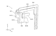
- the ultrasonic motor 64 has a resonance portion 641, a piezoelectric element 642, a first electrode 643, and a second electrode 644.
- the ⁇ side ultrasonic motor 64 in the Y direction corresponds to the “first ultrasonic motor” of the present invention
- the + side ultrasonic motor 64 in the Y direction corresponds to the “second ultrasonic motor” of the present invention. Corresponds to.
- the resonance portion 641 is formed of, for example, a conductive material, resonates with the vibration of the piezoelectric element 642, and converts the vibration motion into the linear motion of the frame 61. Specifically, the resonance portion 641 vibrates in an inclined direction inclined with respect to the direction of the optical axis (Y direction) based on the vibration of the piezoelectric element 642 and presses the intervening portion 63 to press the intervening portion 63. A thrust that moves in the direction of the optical axis is generated in the frame 61 via the frame 61.
- the resonance portion 641 is arranged so as to be sandwiched between the two contact portions 632B in the intervening portion 63. As shown in FIG. 16, the resonance portion 641 has a body portion 641A, two vibrators 641B, a protruding portion 641C, and an energizing portion 641D.
- the body portion 641A is formed, for example, in a substantially rectangular shape, and is a portion sandwiched between the piezoelectric elements 642.
- the two vibrators 641B extend in the Y direction from both ends of the body portion 641A in the Z direction.
- the two vibrators 641B have a symmetrical shape, and their free ends come into contact with the contact portion 632B of the intervening portion 63.
- the two oscillators 641B correspond to the "first oscillator” and the "second oscillator” of the present invention.
- the protruding portion 641C extends from the central portion of the body portion 641A in the Z direction to the + side in the Y direction.
- the energizing portion 641D extends from the central portion of the body portion 641A in the Z direction to the side opposite to the protruding portion 641C (-side in the Y direction).
- the piezoelectric element 642 is, for example, a vibrating element formed of a ceramic material, for example, in a plate shape, and generates vibration by applying a high frequency voltage.
- Two piezoelectric elements 642 are provided, and are arranged so as to sandwich the body portion 641A of the resonance portion 641 in the X direction.
- the first electrode 643 has a sandwiching portion 643A that sandwiches the resonance portion 641 and the piezoelectric element 642, and an electrode portion 643B to which a voltage is applied.
- the first electrode 643 applies a voltage to the piezoelectric element 642 via the sandwiching portion 643A that sandwiches the piezoelectric element 642 or the like.
- the second electrode 644 is electrically connected to the energized portion 641D of the resonance portion 641.
- the first electrode 643 and the second electrode 644 come into contact with the terminal of the terminal portion 111C described above inside the housing 10.
- Two piezoelectric elements 642 are attached to the body portion 641A of the resonance portion 641 and sandwiched between the first electrodes 643, so that they are electrically connected to each other. For example, when one of the feeding paths is connected to the first electrode 643 and the other is connected to the second electrode 644, a voltage is applied to the piezoelectric element 642 and vibration is generated.
- the resonance unit 641 has at least two resonance frequencies and deforms with different behaviors with respect to each resonance frequency.
- the overall shape of the resonant portion 641 is set so that it deforms with different behaviors with respect to the two resonant frequencies.
- the different behaviors are the behavior of moving the frame 61 to the + side in the Y direction via the intervening portion 63 and the behavior of moving the frame 61 to the ⁇ side.
- the resonance portion 641 is arranged so that the vibrator 641B faces any of the pair of contact portions 632B of the intervening portion 63, each contact when the two vibrators 641B are deformed.
- the tip of the vibrator 641B presses the contact portion 632B in a direction inclined with respect to the Y direction from the opposite side of the portion 632B (see arrow A).
- each contact portion 632B When each contact portion 632B is pressed in the direction of arrow A by the tip of the vibrator 641B, a reaction force is generated at each contact portion 632B to return to the vibrator 641B side.
- the intervening portion 63 generates a reaction force in the direction from the outside to the inside of the pair of contact portions 632B based on the contact between each vibrator 641B and the pair of contact portions 632B.
- the reaction force of the intervening portion 63 with respect to the pressing of the vibrator 641B causes the friction generated between the vibrator 641B and the contact portion 632B, and a thrust in the Y direction is generated in the intervening portion 63.
- a thrust (see arrow B) that moves in the Y direction is applied to the frame 61 that is adhered to the intervening portion 63.
- the second lens unit 32 or the third lens unit 33 connected to the frame 61 moves in the Y direction.
- the contact portion 632B is configured to extend in the Y direction, the contact portion 632B is pressed by the vibrator 641B and moves in the Y direction while making contact with the vibrator 641B so as to slide. Therefore, since the contact portion 632B is continuously pressed by the vibrator 641B, the frame 61 bonded to the intervening portion 63 can be continuously moved in the Y direction.
- the pressing direction of the vibrator 641B is the direction of arrow A
- the sliding direction of the contact portion 632B is the direction of arrow B
- the pressing direction of the vibrator 641B is In the direction of arrow C
- the sliding direction of the contact portion 632B is in the direction of arrow D.
- each of the ultrasonic motors 64 provided on the first walls 111 on both sides in the X direction. That is, each ultrasonic motor 64 independently drives each of the second lens unit 32 and the third lens unit 33 in the direction of the optical axis.
- the guide portion 80 is arranged in the region of the fourth wall 114 surrounded by the first wall 111, the second wall 112, and the third wall 113 on the + side in the X direction. That is, the guide portion 80 is arranged on one end side of both ends of the housing 10 that sandwiches the optical axis O in the second lens unit 32 and the third lens unit 33 (see also FIG. 7).
- the first guide portions 80 extend in the direction of the optical axis (Y direction) and are arranged apart from each other so as to support both of the two frames 61 so as to be movable in the direction of the optical axis. It has a guide shaft 81 and a second guide shaft 82.
- the first guide shaft 81 and the second guide shaft 82 are made of, for example, stainless steel, and support the guides of the second wall 112 and the third wall 113 on both end sides (both ends in the X direction) of the optical axis in the housing 10. It is supported by a part (not shown).
- the second wall 112 and the third wall 113 correspond to a "pair of walls" extending from the bottom wall (fourth wall 114) of the present invention.
- the first guide shaft 81 is a guide shaft that guides the movement of the frame 61 by supporting the second portion 611B and the third portion 611C of the guided portion 611 in the frame 61.
- the second guide shaft 82 is arranged parallel to the first guide shaft 81 on the ⁇ side (fourth wall 114 side) in the Z direction of the first guide shaft 81, and is the second portion 611B of the guided portion 611 in the frame 61. It is a guide shaft that guides the movement of the frame 61 by supporting (engaging) the frame 61. Further, the first guide shaft 81 and the second guide shaft 82 are arranged at substantially the same positions as the above-mentioned support shaft 50 in the X direction (see FIG. 10). As described above, the strength of the housing 10 can be improved by providing two guide shafts, the first guide shaft 81 and the second guide shaft 82, for guiding the movement of the lens driving unit 60.
- the second guide shaft 82 is supported by a bearing portion 114A provided on the fourth wall 114.
- the bearing portion 114A is provided between the two frames 61 so as to project from the fourth wall 114 on the + side in the Z direction, and is arranged in a range near the central portion in the Y direction of the second guide shaft 82.
- the second guide shaft 82 is adhesively fixed to the bearing portion 114A. Further, the bearing portion 114A is arranged in a range including the center 82A of the second guide shaft 82 in the X direction (between both ends sandwiching the optical axis) (see FIG. 10).
- the bearing portion 114A is provided at a position where it can come into contact with the second portion 611B of the frame 61. Therefore, when the frame 61 moves to the + side in the Y direction, the second portion 611B of the frame 61 and the bearing portion 114A come into contact with each other (see FIG. 19). As a result, the bearing portion 114A restricts the movement of the frame 61.
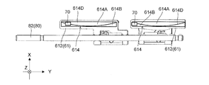
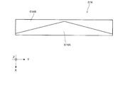
- the magnet portion 614 has a first pole 614A and a second pole 614B arranged adjacent to each other via a boundary 614D in the X direction (width direction orthogonal to the Y direction).
- the first pole 614A is an N-pole magnet
- the second pole 614B is an S-pole magnet. That is, the first pole 614A and the second pole 614B are in the direction in which the magnet unit 614 and the position detection unit 70 face each other (Z direction in the present embodiment) and face the position detection unit 70. As you can see, each is magnetized.
- the first pole 614A and the second pole 614B are arranged in contact with each other. Therefore, the north pole and the south pole are arranged adjacent to each other on the surface 614C facing the position detection unit 70 in the magnet unit 614.
- the magnet unit 614 has a rectangular shape in which the surface 614C facing the position detection unit 70 extends in the Y direction in a state where the first pole 614A and the second pole 614B are in contact with each other. That is, the magnet portion 614 extends linearly along the Y direction with a constant width.
- the adjacent surface of the first pole 614A to the second pole 614B is formed in an arc shape so that the central portion in the Y direction protrudes toward the second pole 614B from both ends in the Y direction.
- the adjacent surface of the second pole 614B to the first pole 614A is configured such that the central portion in the Y direction is recessed from both ends in the Y direction so as to follow the shape of the adjacent surface of the first pole 614A.
- the boundary 614D between the first pole 614A and the second pole 614B is curved (curved in an arc shape) so that the angle formed by the Y direction continuously changes. Specifically, the boundary 614D is displaced from the side of the first pole 614A to the side of the second pole 614B in the X direction as it goes from the end on the ⁇ side of the Y direction to the predetermined position in the magnet portion 614. Further, as the magnet portion 614 moves from the predetermined position to the + side end in the Y direction, the magnet portion 614 bends and extends so as to be displaced from the side of the second pole 614B toward the side of the first pole 614A in the X direction.
- the ratio of the width of the first pole 614A to the width of the second pole 614B is changed by the bending boundary 614D. More specifically, the proportion of the first pole 614A in the first pole 614A and the second pole 614B increases in the Y direction from the negative end of the magnet portion 614 in the Y direction toward a predetermined position. Then, the ratio of the first pole 614A decreases as it goes from the predetermined position to the + side end of the magnet portion 614 in the Y direction.
- the predetermined position is, for example, the central position of the magnet portion 614 in the Y direction. Further, the positions of both ends of the first pole 614A and the second pole 614B in the Y direction in the X direction are the same.
- first pole 614A and the second pole 614B are symmetrically configured on the + side and the-side in the Y direction.
- the distribution of the magnetic force in the magnet portion 614 can be made symmetrical on the + side and the-side with respect to the central portion in the Y direction.
- the magnetic flux density of the magnet unit 614 detected by the position detection unit 70 can be made different depending on the position of the frame 61 (see, for example, FIG. 22).
- the boundary 614D between the first pole 614A and the second pole 614B forms a magnetic field in which the direction of the magnetic flux at the portion of the magnet portion 614 facing the position detection portion 70 changes with the movement of the magnet portion 614. It bends and extends like it does.
- the position detection unit 70 has a magnetic field (magnetic flux density) based on the ratio of N poles and the ratio of S poles in the opposite portion of the magnet unit 614 in the Y direction of the frame 61. It is possible to detect fluctuations according to the movement to.
- the position detection unit 70 faces the + side end portion of the magnet unit 614 in the Y direction.
- the position detection unit 70 faces a portion having a large proportion of the first pole 614A, which is the north pole at the end portion.
- the magnet portion 614 when the frame 61 moves to the + side in the Y direction, the magnet portion 614 also moves together with the frame 61, so that the facing portion of the position detecting portion 70 in the magnet portion 614 changes. As the magnet portion 614 moves toward the central position in the Y direction, the proportion of the first pole 614A increases, so that the proportion of the first pole 614A in the portion facing the position detecting portion 70 gradually increases.
- the portion where the ratio of the first pole 614A (N pole) is maximized becomes the portion facing the position detection unit 70.
- the position detection unit 70 detects the magnetic flux density at each position in the Y direction of the magnet unit 614.
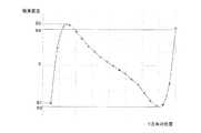
- the change in the magnetic flux density detected by the position detection unit 70 at this time is, for example, a change as shown in FIG. 22.
- the magnetic flux density sharply increases from B1 on the-side from 0 to B2 on the + side from 0, and then to B3 on the-side from 0. It gradually becomes lower. Then, the magnetic flux density sharply increases from B3 to B4 on the + side of 0.
- the magnetic flux corresponding to each position in the Y direction of the frame 61 can be assigned at approximately even intervals. As a result, it is possible to accurately detect the change in the position of the frame 61 (magnet portion 614) in the Y direction in the Y direction.
- the position detection unit 70 since the magnetic flux density detected by the position detection unit 70 can be made different for each position of the frame 61, the position detection unit 70 can accurately detect the position of the frame 61 in the Y direction. can.
- the position detection unit 70 is a magnetoresistive element, it is possible to detect the magnetic force in the horizontal direction (X direction and Y direction) in the magnet unit 614.
- the position detection unit is a Hall element
- the magnetic force in the vertical direction (Z direction) in the magnet unit is detected. Therefore, for example, if the position of the magnet portion shifts in the X direction due to an assembly error, the magnet portion may deviate from the detection range of the position detection unit and the magnetic force may not be detected, which in turn leads to an accurate position of the frame (movable lens). It may not be possible to detect.
- the position detection unit 70 is a magnetoresistive element
- the detection range of the magnetic force in the horizontal direction can be expanded as compared with the position detection unit of the Hall element.
- the magnetic force in the magnet portion 614 can be detected, and by extension, the accurate position of the frame 61 (movable lens) can be detected. Can be done.
- the distribution of the magnetic force can be made symmetrical accordingly.
- the slope of the change in the magnetic flux density in the position detection unit 70 can be made substantially constant (for example, between B2 and B3 in FIG. 22), so that the change in the magnetic flux density at each position in the Y direction can be made substantially constant. can do.
- the magnetic flux density can be assigned to each position in the Y direction at equal intervals, the position of the frame 61 (movable lens) in the Y direction can be accurately detected by the position detection unit 70.
- the adjacent surfaces of the first pole 614A and the second pole 614B are formed in an arc shape, but the present invention is not limited to this, and for example, as shown in FIG. 23, the first pole
- the adjacent surfaces of the 1st pole 614A and the 2nd pole 614B may be formed in a triangular shape.
- the adjacent surfaces of the first pole 614A and the second pole 614B may be formed in a staircase shape.
- the first pole 614A and the second pole 614B have symmetrical shapes on both sides in the Y direction, but the present invention is not limited to this, and for example, as shown in FIG. 25, the first pole The pole 614A and the second pole 614B do not have to be symmetrical on both sides in the Y direction.
- FIG. 25 shows that the adjacent surfaces of the first pole 614A and the second pole 614B have a triangular shape.
- the apex position (predetermined position) on the adjacent surface of the first pole 614A is a position shifted to the + side in the Y direction from the central portion in the Y direction of the magnet portion 614.
- the apex position (predetermined position) on the adjacent surface of the first pole 614A is the central portion in the Y direction, and both ends in the Y direction on the adjacent surface of the first pole 614A are in the X direction.
- the positions may be different from each other.
- the position detection unit 70 detects the magnetic flux density of the magnet unit 614, but the present invention is not limited to this.
- the position detection unit 70 may detect the rotation angle of the magnet unit 614 around the Z direction.
- one position detection unit 70 is provided for each frame 61, but the present invention is not limited to this.
- the configuration may include a plurality of position detection units 70 arranged side by side in the direction of the optical axis (Y direction). By doing so, the accuracy of position detection of the frame 61 can be further improved.
- the position detecting unit 70 is a magnetoresistive element, but the present invention is not limited to this, and as long as the magnetic field on the surface including the X direction and the Y direction can be detected, how is it? It may be anything.
- the configuration has two guide shafts, but the present invention is not limited to this, and for example, a configuration having three or more guide shafts may be used, or one guide shaft may be provided. It may have a configuration having.
- the support shafts 50 are provided on both sides in the X direction, but the present invention is not limited to this, and the support shafts 50 may be provided on only one side in the X direction.
- the side wall portion 11 and the bottom wall portion 12 of the housing 10 are insert-molded, but the present invention is not limited to this, and the bottom wall portion is adhered to the side wall portion 11. It may be something like fixing.
- the configuration has two movable lenses composed of the second lens unit 32 and the third lens unit 33, but the present invention is not limited to this, and the present invention is not limited to this, and three or more movable lenses. It may have a structure having one movable lens, or it may have a structure having one movable lens.
- the configuration has four lens units, but the present invention is not limited to this, and as long as the configuration has at least one movable lens, a number of lens units are provided. Is also good. Further, in the case of the configuration having one movable lens, the lens driving unit is also one.
- the intervening portion 63 is formed by bending a plate-shaped metal member, but the present invention is not limited to this, and the main body portion and the contact portion constituting the intervening portion are formed. It may be composed of different members.
- the frame 61 and the intervening portion 63 are composed of separate members, but the present invention is not limited to this.
- the frame 61 and the intervening portion 63 may be integrally configured. That is, the lens driving unit may have a moving unit that moves in the direction of the optical axis according to the resonance of the resonance unit and is connected to each lens unit so as to transmit the movement in the direction of the optical axis.
- the connecting portion 62 connecting the frame 61 and the lens unit is composed of a spring member, but the present invention is not limited to this, and any member as long as it is an elastic member. It may be composed of members.
- the third portion 611C of the frame 61 is arranged at a distance from the second guide shaft 82, but the present invention is not limited to this, and the third portion is the second guide shaft. It may be a configuration that also supports.
- the bottom wall portion has a bent portion and a half punch, but the present invention is not limited to this, and a configuration having no bent portion and a half punch may be used.
- the resonance portion 641 has a configuration having two vibrators 641B, but the present invention is not limited to this, and for example, a configuration having one vibrator may be used.
- the drive control unit, the reflection drive control unit, and the image pickup control unit are separately provided, but the present invention is not limited to this, and the drive control unit, the reflection drive control unit, and the image pickup control unit are provided. At least two of them may be composed of one control unit.
- the bearing portion 114A is provided, but the present invention is not limited to this, and the bearing portion may not be provided.
- the absorption unit 613 is provided, but the present invention is not limited to this, and the absorption unit may not be provided.
- a smartphone which is a mobile terminal with a camera
- a camera-mounted device including the camera module 1 has been described as an example of a camera-mounted device including the camera module 1.
- the present invention has described the images obtained by the camera module and the camera module. It can be applied to a camera-mounted device having an image processing unit that processes information.
- Camera-mounted devices include information devices and transportation devices.
- the information device includes, for example, a mobile phone with a camera, a notebook computer, a tablet terminal, a portable game machine, a web camera, a drone, and an in-vehicle device with a camera (for example, a back monitor device and a drive recorder device).
- Transportation equipment also includes, for example, automobiles and drones.
- 29A and 29B are diagrams showing an automobile V as a camera-mounted device on which an in-vehicle camera module VC (Vehicle Camera) is mounted.
- 29A is a front view of the automobile V
- FIG. 29B is a rear perspective view of the automobile V.
- the automobile V is equipped with the camera module 1 described in the embodiment as the in-vehicle camera module VC.
- the vehicle-mounted camera module VC may be attached to the windshield toward the front or attached to the rear gate toward the rear, for example.
- This in-vehicle camera module VC is used for a back monitor, a drive recorder, a collision avoidance control, an automatic driving control, and the like.
- the above embodiments are merely examples of embodiment of the present invention, and the technical scope of the present invention should not be construed in a limited manner by these. That is, the present invention can be implemented in various forms without departing from its gist or its main features. For example, the shape, size, number, and material of each part described in the above embodiment are merely examples, and can be changed as appropriate.
- the lens driving device is useful as a lens driving device, a camera module, and a camera-mounted device capable of accurately detecting the position of a movable lens.
- Imaging part 10 Housing 11 Side wall 12 Bottom wall 20 Reflective drive 21 Reflective housing 22 Mirror 23 Reflective drive control 30 Lens 31 1st lens unit 32 2nd lens unit 32A Main body 32B Supported part 33 3 Lens unit 33A Main body 33B Supported part 34 4th lens unit 34A Convex part 40 Imaging part 50 Supporting shaft 60 Lens driving part 61 Frame 62 Connection part 63 Intervening part 64 Ultrasonic motor 70 Position detection part 80 Guide part 81 1st Guide shaft 82 2nd guide shaft 100 Drive control unit 111 1st wall 111A Arrangement part 111B Engagement part 111C Terminal part 112 2nd wall 112A Support part 112B Arrangement part 112C Guide support part 112D Opening part 113 3rd wall 113A Bridge part 113B Support part 113C Guide support part 114 4th wall 114A Bearing part 121 Positioning part 122 Bending part 123 Half punch 200 Imaging control part 611 Guided part 611A 1st part 611B 2nd part 611C 3rd part 611D 4
Landscapes
- Physics & Mathematics (AREA)
- General Physics & Mathematics (AREA)
- Engineering & Computer Science (AREA)
- Optics & Photonics (AREA)
- Power Engineering (AREA)
- General Engineering & Computer Science (AREA)
- Chemical & Material Sciences (AREA)
- Combustion & Propulsion (AREA)
- Electromagnetism (AREA)
- Microelectronics & Electronic Packaging (AREA)
- Mechanical Engineering (AREA)
- Lens Barrels (AREA)
Priority Applications (4)
| Application Number | Priority Date | Filing Date | Title |
|---|---|---|---|
| US17/907,411 US12306460B2 (en) | 2020-03-30 | 2021-03-11 | Lens driving device, camera module, and camera-equipped device |
| KR1020227033487A KR102930717B1 (ko) | 2020-03-30 | 2021-03-11 | 렌즈 구동 장치, 카메라 모듈 및 카메라 탑재 장치 |
| JP2022511756A JP7617447B2 (ja) | 2020-03-30 | 2021-03-11 | レンズ駆動装置、カメラモジュールおよびカメラ搭載装置 |
| CN202180025502.8A CN115349103B (zh) | 2020-03-30 | 2021-03-11 | 透镜驱动装置、摄像机模块及摄像机搭载装置 |
Applications Claiming Priority (2)
| Application Number | Priority Date | Filing Date | Title |
|---|---|---|---|
| US202063002300P | 2020-03-30 | 2020-03-30 | |
| US63/002,300 | 2020-03-30 |
Publications (1)
| Publication Number | Publication Date |
|---|---|
| WO2021200012A1 true WO2021200012A1 (ja) | 2021-10-07 |
Family
ID=77927910
Family Applications (1)
| Application Number | Title | Priority Date | Filing Date |
|---|---|---|---|
| PCT/JP2021/009773 Ceased WO2021200012A1 (ja) | 2020-03-30 | 2021-03-11 | レンズ駆動装置、カメラモジュールおよびカメラ搭載装置 |
Country Status (5)
| Country | Link |
|---|---|
| US (1) | US12306460B2 (https=) |
| JP (1) | JP7617447B2 (https=) |
| KR (1) | KR102930717B1 (https=) |
| CN (1) | CN115349103B (https=) |
| WO (1) | WO2021200012A1 (https=) |
Families Citing this family (1)
| Publication number | Priority date | Publication date | Assignee | Title |
|---|---|---|---|---|
| JP7662139B2 (ja) * | 2021-09-24 | 2025-04-15 | アルプスアルパイン株式会社 | レンズホルダ駆動装置 |
Citations (3)
| Publication number | Priority date | Publication date | Assignee | Title |
|---|---|---|---|---|
| WO2006115129A1 (ja) * | 2005-04-19 | 2006-11-02 | Matsushita Electric Industrial Co., Ltd. | 位置センサ、光ヘッド装置、ヘッド移動機構、情報記録再生装置、および位置制御システム |
| JP2016133371A (ja) * | 2015-01-19 | 2016-07-25 | キヤノン株式会社 | 磁気式位置検出装置、駆動装置および光学機器 |
| JP2019187119A (ja) * | 2018-04-11 | 2019-10-24 | キヤノン株式会社 | 駆動装置、像ぶれ補正装置及び撮像装置 |
Family Cites Families (11)
| Publication number | Priority date | Publication date | Assignee | Title |
|---|---|---|---|---|
| JP4522027B2 (ja) * | 2001-07-31 | 2010-08-11 | パイオニア株式会社 | アクチュエータ用マグネット、アクチュエータ、および、着磁装置 |
| US7702233B2 (en) | 2003-12-19 | 2010-04-20 | Hysonic Co., Ltd. | Image photographing apparatus |
| KR101222860B1 (ko) * | 2005-09-01 | 2013-01-16 | 삼성전자주식회사 | 광픽업장치 |
| CN101206296B (zh) | 2006-12-22 | 2010-05-19 | 鸿富锦精密工业(深圳)有限公司 | 镜头模组 |
| JP2012068339A (ja) * | 2010-09-22 | 2012-04-05 | Ps-Tokki Inc | 位置検出センサ及びレンズ駆動装置 |
| JP5675009B2 (ja) | 2012-11-07 | 2015-02-25 | 三菱電機株式会社 | 位置検出装置 |
| JP6806991B2 (ja) | 2016-08-30 | 2021-01-06 | ミツミ電機株式会社 | カメラモジュール |
| DE102016225900A1 (de) * | 2016-12-21 | 2018-06-21 | Carl Zeiss Smt Gmbh | Tauchspulenaktuator |
| KR102003282B1 (ko) | 2017-06-29 | 2019-07-24 | 성우전자 주식회사 | 틸트 성능이 개선된 통합액추에이터 |
| JP7057492B2 (ja) * | 2017-12-28 | 2022-04-20 | ミツミ電機株式会社 | レンズ駆動装置、カメラモジュール、及びカメラ搭載装置 |
| KR102859287B1 (ko) * | 2019-04-26 | 2025-09-12 | 엘지이노텍 주식회사 | 카메라 모듈 및 이를 포함하는 카메라 장치 |
-
2021
- 2021-03-11 CN CN202180025502.8A patent/CN115349103B/zh active Active
- 2021-03-11 JP JP2022511756A patent/JP7617447B2/ja active Active
- 2021-03-11 WO PCT/JP2021/009773 patent/WO2021200012A1/ja not_active Ceased
- 2021-03-11 KR KR1020227033487A patent/KR102930717B1/ko active Active
- 2021-03-11 US US17/907,411 patent/US12306460B2/en active Active
Patent Citations (3)
| Publication number | Priority date | Publication date | Assignee | Title |
|---|---|---|---|---|
| WO2006115129A1 (ja) * | 2005-04-19 | 2006-11-02 | Matsushita Electric Industrial Co., Ltd. | 位置センサ、光ヘッド装置、ヘッド移動機構、情報記録再生装置、および位置制御システム |
| JP2016133371A (ja) * | 2015-01-19 | 2016-07-25 | キヤノン株式会社 | 磁気式位置検出装置、駆動装置および光学機器 |
| JP2019187119A (ja) * | 2018-04-11 | 2019-10-24 | キヤノン株式会社 | 駆動装置、像ぶれ補正装置及び撮像装置 |
Also Published As
| Publication number | Publication date |
|---|---|
| CN115349103A (zh) | 2022-11-15 |
| US12306460B2 (en) | 2025-05-20 |
| US20230121120A1 (en) | 2023-04-20 |
| JP7617447B2 (ja) | 2025-01-20 |
| KR20220159993A (ko) | 2022-12-05 |
| KR102930717B1 (ko) | 2026-02-24 |
| CN115349103B (zh) | 2026-04-21 |
| JPWO2021200012A1 (https=) | 2021-10-07 |
Similar Documents
| Publication | Publication Date | Title |
|---|---|---|
| JP7128327B2 (ja) | 板状超音波モータ、レンズ駆動装置、カメラモジュール、及びカメラ搭載装置 | |
| JP7648937B2 (ja) | カメラモジュールおよびカメラ搭載装置 | |
| JP7096521B2 (ja) | 光学素子駆動装置 | |
| JP7617447B2 (ja) | レンズ駆動装置、カメラモジュールおよびカメラ搭載装置 | |
| JP7575699B2 (ja) | レンズ駆動装置、カメラモジュールおよびカメラ搭載装置 | |
| WO2022102306A1 (ja) | 駆動ユニット、レンズ駆動装置、カメラモジュールおよびカメラ搭載装置 | |
| JP7440781B2 (ja) | レンズ駆動装置、カメラモジュールおよびカメラ搭載装置 | |
| JP7093050B2 (ja) | レンズ駆動装置、カメラモジュール、及びカメラ搭載装置 | |
| JP2025092108A (ja) | 光学素子駆動装置、カメラモジュールおよびカメラ搭載装置 |
Legal Events
| Date | Code | Title | Description |
|---|---|---|---|
| 121 | Ep: the epo has been informed by wipo that ep was designated in this application |
Ref document number: 21779354 Country of ref document: EP Kind code of ref document: A1 |
|
| ENP | Entry into the national phase |
Ref document number: 2022511756 Country of ref document: JP Kind code of ref document: A |
|
| NENP | Non-entry into the national phase |
Ref country code: DE |
|
| 122 | Ep: pct application non-entry in european phase |
Ref document number: 21779354 Country of ref document: EP Kind code of ref document: A1 |
|
| WWG | Wipo information: grant in national office |
Ref document number: 17907411 Country of ref document: US |