WO2021200012A1 - Lens driving device, camera module, and camera-equipped device - Google Patents
Lens driving device, camera module, and camera-equipped device Download PDFInfo
- Publication number
- WO2021200012A1 WO2021200012A1 PCT/JP2021/009773 JP2021009773W WO2021200012A1 WO 2021200012 A1 WO2021200012 A1 WO 2021200012A1 JP 2021009773 W JP2021009773 W JP 2021009773W WO 2021200012 A1 WO2021200012 A1 WO 2021200012A1
- Authority
- WO
- WIPO (PCT)
- Prior art keywords
- unit
- optical axis
- lens
- pole
- movable
- Prior art date
Links
- 230000003287 optical effect Effects 0.000 claims abstract description 56
- 238000001514 detection method Methods 0.000 claims abstract description 53
- 238000005452 bending Methods 0.000 claims abstract description 7
- 230000004907 flux Effects 0.000 claims description 18
- 238000003384 imaging method Methods 0.000 claims description 8
- 238000000034 method Methods 0.000 claims description 4
- 230000008569 process Effects 0.000 claims description 4
- 230000008859 change Effects 0.000 description 7
- 238000010521 absorption reaction Methods 0.000 description 6
- 230000006399 behavior Effects 0.000 description 5
- 230000006870 function Effects 0.000 description 4
- 239000002184 metal Substances 0.000 description 4
- 229910052751 metal Inorganic materials 0.000 description 4
- 230000004048 modification Effects 0.000 description 4
- 238000012986 modification Methods 0.000 description 4
- 238000003825 pressing Methods 0.000 description 4
- 239000000758 substrate Substances 0.000 description 4
- 238000006243 chemical reaction Methods 0.000 description 3
- 238000010586 diagram Methods 0.000 description 3
- 230000007423 decrease Effects 0.000 description 2
- 238000009826 distribution Methods 0.000 description 2
- 230000000149 penetrating effect Effects 0.000 description 2
- 229910001220 stainless steel Inorganic materials 0.000 description 2
- 239000010935 stainless steel Substances 0.000 description 2
- 229910010293 ceramic material Inorganic materials 0.000 description 1
- 230000000295 complement effect Effects 0.000 description 1
- 239000004020 conductor Substances 0.000 description 1
- 238000004132 cross linking Methods 0.000 description 1
- 238000006073 displacement reaction Methods 0.000 description 1
- 238000004519 manufacturing process Methods 0.000 description 1
- 239000000463 material Substances 0.000 description 1
- 229910044991 metal oxide Inorganic materials 0.000 description 1
- 150000004706 metal oxides Chemical class 0.000 description 1
- 238000000465 moulding Methods 0.000 description 1
- 239000011347 resin Substances 0.000 description 1
- 229920005989 resin Polymers 0.000 description 1
- 239000004065 semiconductor Substances 0.000 description 1
- 230000006641 stabilisation Effects 0.000 description 1
- 238000011105 stabilization Methods 0.000 description 1
- 238000011144 upstream manufacturing Methods 0.000 description 1
Images


Classifications
-
- G—PHYSICS
- G02—OPTICS
- G02B—OPTICAL ELEMENTS, SYSTEMS OR APPARATUS
- G02B13/00—Optical objectives specially designed for the purposes specified below
- G02B13/001—Miniaturised objectives for electronic devices, e.g. portable telephones, webcams, PDAs, small digital cameras
- G02B13/0055—Miniaturised objectives for electronic devices, e.g. portable telephones, webcams, PDAs, small digital cameras employing a special optical element
- G02B13/0065—Miniaturised objectives for electronic devices, e.g. portable telephones, webcams, PDAs, small digital cameras employing a special optical element having a beam-folding prism or mirror
-
- G—PHYSICS
- G03—PHOTOGRAPHY; CINEMATOGRAPHY; ANALOGOUS TECHNIQUES USING WAVES OTHER THAN OPTICAL WAVES; ELECTROGRAPHY; HOLOGRAPHY
- G03B—APPARATUS OR ARRANGEMENTS FOR TAKING PHOTOGRAPHS OR FOR PROJECTING OR VIEWING THEM; APPARATUS OR ARRANGEMENTS EMPLOYING ANALOGOUS TECHNIQUES USING WAVES OTHER THAN OPTICAL WAVES; ACCESSORIES THEREFOR
- G03B5/00—Adjustment of optical system relative to image or object surface other than for focusing
- G03B5/04—Vertical adjustment of lens; Rising fronts
-
- G—PHYSICS
- G02—OPTICS
- G02B—OPTICAL ELEMENTS, SYSTEMS OR APPARATUS
- G02B7/00—Mountings, adjusting means, or light-tight connections, for optical elements
- G02B7/02—Mountings, adjusting means, or light-tight connections, for optical elements for lenses
- G02B7/04—Mountings, adjusting means, or light-tight connections, for optical elements for lenses with mechanism for focusing or varying magnification
- G02B7/10—Mountings, adjusting means, or light-tight connections, for optical elements for lenses with mechanism for focusing or varying magnification by relative axial movement of several lenses, e.g. of varifocal objective lens
- G02B7/102—Mountings, adjusting means, or light-tight connections, for optical elements for lenses with mechanism for focusing or varying magnification by relative axial movement of several lenses, e.g. of varifocal objective lens controlled by a microcomputer
-
- B—PERFORMING OPERATIONS; TRANSPORTING
- B06—GENERATING OR TRANSMITTING MECHANICAL VIBRATIONS IN GENERAL
- B06B—METHODS OR APPARATUS FOR GENERATING OR TRANSMITTING MECHANICAL VIBRATIONS OF INFRASONIC, SONIC, OR ULTRASONIC FREQUENCY, e.g. FOR PERFORMING MECHANICAL WORK IN GENERAL
- B06B1/00—Methods or apparatus for generating mechanical vibrations of infrasonic, sonic, or ultrasonic frequency
- B06B1/02—Methods or apparatus for generating mechanical vibrations of infrasonic, sonic, or ultrasonic frequency making use of electrical energy
- B06B1/06—Methods or apparatus for generating mechanical vibrations of infrasonic, sonic, or ultrasonic frequency making use of electrical energy operating with piezoelectric effect or with electrostriction
-
- G—PHYSICS
- G02—OPTICS
- G02B—OPTICAL ELEMENTS, SYSTEMS OR APPARATUS
- G02B13/00—Optical objectives specially designed for the purposes specified below
- G02B13/001—Miniaturised objectives for electronic devices, e.g. portable telephones, webcams, PDAs, small digital cameras
- G02B13/009—Miniaturised objectives for electronic devices, e.g. portable telephones, webcams, PDAs, small digital cameras having zoom function
-
- G—PHYSICS
- G02—OPTICS
- G02B—OPTICAL ELEMENTS, SYSTEMS OR APPARATUS
- G02B7/00—Mountings, adjusting means, or light-tight connections, for optical elements
- G02B7/02—Mountings, adjusting means, or light-tight connections, for optical elements for lenses
- G02B7/04—Mountings, adjusting means, or light-tight connections, for optical elements for lenses with mechanism for focusing or varying magnification
- G02B7/08—Mountings, adjusting means, or light-tight connections, for optical elements for lenses with mechanism for focusing or varying magnification adapted to co-operate with a remote control mechanism
-
- G—PHYSICS
- G02—OPTICS
- G02B—OPTICAL ELEMENTS, SYSTEMS OR APPARATUS
- G02B7/00—Mountings, adjusting means, or light-tight connections, for optical elements
- G02B7/02—Mountings, adjusting means, or light-tight connections, for optical elements for lenses
- G02B7/04—Mountings, adjusting means, or light-tight connections, for optical elements for lenses with mechanism for focusing or varying magnification
- G02B7/09—Mountings, adjusting means, or light-tight connections, for optical elements for lenses with mechanism for focusing or varying magnification adapted for automatic focusing or varying magnification
-
- G—PHYSICS
- G03—PHOTOGRAPHY; CINEMATOGRAPHY; ANALOGOUS TECHNIQUES USING WAVES OTHER THAN OPTICAL WAVES; ELECTROGRAPHY; HOLOGRAPHY
- G03B—APPARATUS OR ARRANGEMENTS FOR TAKING PHOTOGRAPHS OR FOR PROJECTING OR VIEWING THEM; APPARATUS OR ARRANGEMENTS EMPLOYING ANALOGOUS TECHNIQUES USING WAVES OTHER THAN OPTICAL WAVES; ACCESSORIES THEREFOR
- G03B17/00—Details of cameras or camera bodies; Accessories therefor
- G03B17/02—Bodies
- G03B17/12—Bodies with means for supporting objectives, supplementary lenses, filters, masks, or turrets
-
- G—PHYSICS
- G03—PHOTOGRAPHY; CINEMATOGRAPHY; ANALOGOUS TECHNIQUES USING WAVES OTHER THAN OPTICAL WAVES; ELECTROGRAPHY; HOLOGRAPHY
- G03B—APPARATUS OR ARRANGEMENTS FOR TAKING PHOTOGRAPHS OR FOR PROJECTING OR VIEWING THEM; APPARATUS OR ARRANGEMENTS EMPLOYING ANALOGOUS TECHNIQUES USING WAVES OTHER THAN OPTICAL WAVES; ACCESSORIES THEREFOR
- G03B17/00—Details of cameras or camera bodies; Accessories therefor
- G03B17/02—Bodies
- G03B17/17—Bodies with reflectors arranged in beam forming the photographic image, e.g. for reducing dimensions of camera
-
- H—ELECTRICITY
- H02—GENERATION; CONVERSION OR DISTRIBUTION OF ELECTRIC POWER
- H02K—DYNAMO-ELECTRIC MACHINES
- H02K11/00—Structural association of dynamo-electric machines with electric components or with devices for shielding, monitoring or protection
- H02K11/20—Structural association of dynamo-electric machines with electric components or with devices for shielding, monitoring or protection for measuring, monitoring, testing, protecting or switching
- H02K11/21—Devices for sensing speed or position, or actuated thereby
- H02K11/215—Magnetic effect devices, e.g. Hall-effect or magneto-resistive elements
-
- H—ELECTRICITY
- H02—GENERATION; CONVERSION OR DISTRIBUTION OF ELECTRIC POWER
- H02K—DYNAMO-ELECTRIC MACHINES
- H02K41/00—Propulsion systems in which a rigid body is moved along a path due to dynamo-electric interaction between the body and a magnetic field travelling along the path
- H02K41/02—Linear motors; Sectional motors
- H02K41/035—DC motors; Unipolar motors
- H02K41/0352—Unipolar motors
- H02K41/0354—Lorentz force motors, e.g. voice coil motors
- H02K41/0356—Lorentz force motors, e.g. voice coil motors moving along a straight path
-
- G—PHYSICS
- G03—PHOTOGRAPHY; CINEMATOGRAPHY; ANALOGOUS TECHNIQUES USING WAVES OTHER THAN OPTICAL WAVES; ELECTROGRAPHY; HOLOGRAPHY
- G03B—APPARATUS OR ARRANGEMENTS FOR TAKING PHOTOGRAPHS OR FOR PROJECTING OR VIEWING THEM; APPARATUS OR ARRANGEMENTS EMPLOYING ANALOGOUS TECHNIQUES USING WAVES OTHER THAN OPTICAL WAVES; ACCESSORIES THEREFOR
- G03B2205/00—Adjustment of optical system relative to image or object surface other than for focusing
- G03B2205/0007—Movement of one or more optical elements for control of motion blur
- G03B2205/0023—Movement of one or more optical elements for control of motion blur by tilting or inclining one or more optical elements with respect to the optical axis
-
- G—PHYSICS
- G03—PHOTOGRAPHY; CINEMATOGRAPHY; ANALOGOUS TECHNIQUES USING WAVES OTHER THAN OPTICAL WAVES; ELECTROGRAPHY; HOLOGRAPHY
- G03B—APPARATUS OR ARRANGEMENTS FOR TAKING PHOTOGRAPHS OR FOR PROJECTING OR VIEWING THEM; APPARATUS OR ARRANGEMENTS EMPLOYING ANALOGOUS TECHNIQUES USING WAVES OTHER THAN OPTICAL WAVES; ACCESSORIES THEREFOR
- G03B2205/00—Adjustment of optical system relative to image or object surface other than for focusing
- G03B2205/0053—Driving means for the movement of one or more optical element
- G03B2205/0061—Driving means for the movement of one or more optical element using piezoelectric actuators
-
- G—PHYSICS
- G03—PHOTOGRAPHY; CINEMATOGRAPHY; ANALOGOUS TECHNIQUES USING WAVES OTHER THAN OPTICAL WAVES; ELECTROGRAPHY; HOLOGRAPHY
- G03B—APPARATUS OR ARRANGEMENTS FOR TAKING PHOTOGRAPHS OR FOR PROJECTING OR VIEWING THEM; APPARATUS OR ARRANGEMENTS EMPLOYING ANALOGOUS TECHNIQUES USING WAVES OTHER THAN OPTICAL WAVES; ACCESSORIES THEREFOR
- G03B2205/00—Adjustment of optical system relative to image or object surface other than for focusing
- G03B2205/0053—Driving means for the movement of one or more optical element
- G03B2205/0069—Driving means for the movement of one or more optical element using electromagnetic actuators, e.g. voice coils
Definitions
- the present invention relates to a lens driving device, a camera module, and a camera mounting device.
- a camera module mounted on a thin camera-mounted device such as a smartphone is known.
- a camera module is known to include a lens driving device having a zoom function for enlarging or reducing a subject image.
- Patent Document 1 describes a fixed lens in which light from a subject is incident, two movable lenses in which light bent by the fixed lens is incident, and a lens drive that moves the two movable lenses in the direction of the optical axis.
- a configuration including a part is disclosed.
- a magnet portion is provided in the movable portion provided with the movable lens, and a position detecting portion (for example, a hole) for detecting the magnetic flux of the magnet portion. Element) and.
- a position detecting portion for example, a hole
- the magnet portion for example, two different poles (N pole and S pole) are arranged adjacent to each other, and the magnetic force at the portion facing the position detection portion is arranged so as to change according to the position of the movable lens.
- An object of the present invention is to provide a lens driving device, a camera module, and a camera mounting device capable of accurately detecting the position of a movable lens.
- the lens driving device is A movable part that is arranged in the direction of the optical axis and can hold a movable lens,
- a drive unit that drives the movable unit in the direction of the optical axis,
- a magnet portion provided on the movable portion, extending in the direction of the optical axis, and having a first pole and a second pole adjacent to each other across a boundary in a width direction orthogonal to the direction of the optical axis.
- a position detection unit that is arranged to face the magnet unit and detects the position of the magnet unit by detecting a magnetic field on a surface including the direction of the optical axis and the width direction. With The boundary bends and extends so that the angle formed with the direction of the optical axis changes.
- the camera module according to the present invention With the above lens drive A lens portion including the movable lens held by the movable portion and An imaging unit that captures a subject image imaged by the lens unit, and an imaging unit. With The movable lens is driven in the direction of the optical axis.
- the camera-mounted device A camera-mounted device that is an information device or a transportation device.
- An image pickup control unit that processes the image information obtained by the camera module, and To be equipped.
- the position of the movable lens can be accurately detected.
- FIG. 1 It is a figure which shows the camera module which concerns on embodiment of this invention simply. It is a figure which shows simply the structure which looked at the side view of the camera module which concerns on this embodiment. It is a perspective view which shows the housing part of a camera module. It is a perspective view of the bottom wall part side in the housing part of a camera module. It is an exploded perspective view of a housing and a lens part. It is an exploded perspective view of the side wall portion and the bottom wall portion in the housing. It is the figure which looked at the housing from the Z direction + side. It is the figure which looked at the inside of the housing from the negative side in the X direction. It is a figure which shows the guided part. It is a figure which shows the connection part of a lens part and a frame.
- FIG. 1 is a diagram simply showing a camera module 1 according to an embodiment of the present invention.
- FIG. 2 is a diagram simply showing a configuration in which the camera module 1 according to the present embodiment is viewed from the side.
- the camera module 1 is mounted on a thin camera-mounted device such as a smartphone M (see FIGS. 28A and 28B), a mobile phone, a digital camera, a notebook computer, a tablet terminal, a portable game machine, and an in-vehicle camera.
- a smartphone M see FIGS. 28A and 28B
- a mobile phone such as a smartphone M (see FIGS. 28A and 28B), a mobile phone, a digital camera, a notebook computer, a tablet terminal, a portable game machine, and an in-vehicle camera.
- a Cartesian coordinate system (X, Y, Z) is used. Also in the figure described later, it is shown by a common Cartesian coordinate system (X, Y, Z).
- the camera module 1 is mounted so that, for example, the X direction is the left-right direction, the Y direction is the up-down direction, and the Z direction is the front-back direction when shooting is actually performed by the camera-mounted device.
- the light from the subject is incident from the-side (minus side) in the Z direction, bends, and is guided to the + side (plus side) in the Y direction.
- the camera module 1 includes a housing 10, a reflection drive unit 20, a lens unit 30, an image pickup unit 40, a support shaft 50 (see FIG. 3), and a lens drive unit 60 (FIG. 5). (See), a position detection unit 70 (see FIG. 10), and a drive control unit 100.
- the drive control unit 100 includes a CPU (Central Processing Unit), a ROM (Read Only Memory), a RAM (Random Access Memory), and the like.
- the CPU reads a program according to the processing content from the ROM, develops it in the RAM, and centrally controls the lens driving unit 60 in cooperation with the expanded program.
- the drive control unit 100 drives the second lens unit 32 and the third lens unit 33, which will be described later, of the lens unit 30 housed in the housing 10 in the Y direction (direction of the optical axis).
- the camera module 1 performs stepless optical zoom and autofocus.
- the housing 10, the support shaft 50, the lens drive unit 60, the position detection unit 70, and the drive control unit 100 correspond to the "lens drive device" of the present invention.
- the reflection drive unit 20 includes a reflection housing 21, a mirror 22, and a reflection drive control unit 23.
- the reflective housing 21 is arranged adjacent to the negative end of the housing 10 in the Y direction.
- the mirror 22 is provided in the reflective housing 21, and reflects the incident light L1 as the reflected light L2 toward the housing 10.
- the reflection drive control unit 23 includes a CPU, ROM, RAM, and the like, and controls the orientation of the mirror 22.
- the mirror 22 has two rotation axes (not shown) extending in the X direction and the Y direction.
- the mirror 22 rotates around the rotation axis under the control of the reflection drive control unit 23.
- the camera module 1 has a shake correction function (OIS (Optical Image Stabilization) function) that optically corrects shake (vibration) that occurs during shooting to reduce image distortion.
- OIS Optical Image Stabilization
- the reflected light L2 incident on the housing 10 is output to the imaging unit 40 via the lens unit 30 housed in the housing 10.
- the image pickup unit 40 is arranged on the outer surface of the housing 10 on the + side in the Y direction (arrangement portion 112B of the second wall 112 described later), and is configured such that the reflected light L2 is incident through the lens portion 30. Has been done.
- the image pickup unit 40 includes an image pickup device, a substrate, and the like (not shown).
- the image sensor is composed of, for example, a CCD (Charge Coupled Device) type image sensor, a CMOS (Complementary Metal Oxide Semiconductor) type image sensor, or the like.
- the image sensor is mounted on the substrate and is electrically connected to the wiring on the substrate via the bonding wire.
- the image sensor captures the subject image formed by the lens unit 30 and outputs an electric signal corresponding to the subject image.
- a printed wiring board (not shown) is electrically connected to the substrate of the image pickup unit 40, and power is supplied to the image sensor via the printed wiring board and an electric signal of the subject image captured by the image sensor is output. Is done.
- the electric signal is output to the image pickup control unit 200 provided in the camera-mounted device.
- the image pickup control unit 200 includes a CPU, a ROM, a RAM, and the like, and processes the image information obtained by the camera module 1.
- the image pickup control unit 200 may be mounted on the camera mounting device, but may be mounted on the camera module 1.
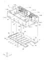
- the housing 10 houses the lens portion 30, the support shaft 50, and the lens driving portion 60 (see also FIG. 5), and has, for example, a rectangular parallelepiped shape as a whole.
- the housing 10 has a side wall portion 11 and a bottom wall portion 12.
- the side wall portion 11 is, for example, a resin wall portion having a portion that opens in the Y direction ⁇ side, and has a first wall 111, a second wall 112, a third wall 113, and a fourth wall 114 (FIG. 7, etc.). See also).
- the first wall 111 is configured to extend in the Y direction, and is provided in pairs on both sides in the X direction.
- an arrangement portion 111A on which an ultrasonic motor, which will be described later, is arranged is provided on the inner surface of the housing 10 on the first wall 111 on the + side in the X direction.
- the arrangement portions 111A are provided on both sides of the central portion in the Y direction on the first wall 111 on the + side in the X direction.
- a terminal portion 111C is provided on the first wall 111 on the + side in the X direction.
- the terminal portion 111C has terminals (not shown) arranged inside and outside the housing 10 through, for example, a gap formed between the first wall 111 and the bottom wall portion 12.
- the portion of the terminal arranged outside the housing 10 is connected to a predetermined wiring of the camera-mounted device.
- an engaged portion 111B with which the positioning portion 121 of the bottom wall portion 12 is engaged is formed.
- the second wall 112 is configured to extend in the X direction and is provided so as to connect the + side ends of the pair of first walls 111 in the Y direction. Further, support portions 112A for supporting the support shaft 50 are provided on both sides in the X direction on the top surface (the surface on the + side in the Z direction) of the second wall 112. On the outer surface of the second wall 112, an arrangement portion 112B on which the imaging unit 40 is arranged is provided.
- a guide support portion 112C and an opening 112D are provided in the arrangement portion 112B of the second wall 112.
- the guide support portion 112C is a hole for supporting the guide shafts 81 and 82 described later, and is provided on the ⁇ side in the X direction with respect to the opening 112D in the arrangement portion 112B.
- Two guide support portions 112C are provided side by side in the Z direction.
- the opening 112D is an opening into which the fourth lens unit 34 of the lens portion 30 fits, and is provided at the central portion in the X direction in the arrangement portion 112B.
- the third wall 113 is provided at each of the negative end portions of the pair of first walls 111 in the Y direction.
- the pair of third walls 113 are provided so as to surround the space composed of the first wall 111 and the second wall 112, respectively.
- the pair of third walls 113 are spaced apart from each other so that the first lens unit 31 of the lens portion 30 can enter, and a cross-linking portion that bridges the negative end portion of each third wall 113 in the Z direction. 113A is provided.
- a support portion 113B for supporting the support shaft 50 is provided on the top surface (the surface on the + side in the Z direction) of the pair of third walls 113.
- the guide support portion 113C is a long hole having a length in the Z direction corresponding to the arrangement range of the two guide support portions 112C on the second wall 112 described above.
- the guide support portion 113C can support the guide shafts 81 and 82 supported by the two guide support portions 112C on the second wall 112, respectively.
- the fourth wall 114 constitutes the bottom wall of the space composed of the first wall 111, the third wall 113 corresponding to the first wall 111, and the second wall 112, respectively. It is provided in the area corresponding to the third wall 113 in the direction (see also FIG. 7). Therefore, there is a gap between the fourth walls 114 on both sides in the X direction.
- the bottom wall portion 12 is, for example, a substantially rectangular metal plate constituting the bottom wall of the housing 10, and the fourth wall 114 and the pair of first walls on both sides in the X direction. It is provided so as to bridge 111.
- the bottom wall portion 12 is integrated with the bottom surface portion of the side wall portion 11 including the bottom portion of the pair of first walls 111 by insert molding. Further, the end portion of the bottom wall portion 12 on the ⁇ side in the Y direction is cut out so that the portion of the bottom wall portion 12 does not exist in the portion corresponding to the first lens unit 31.
- Positioning portions 121 are provided at both ends of the bottom wall portion 12 in the X direction.
- the positioning portion 121 is provided so as to project from both side ends of the bottom wall portion 12, and engages with the engaged portion 111B of the first wall 111 described above. As a result, the bottom wall portion 12 can be positioned in the Y direction.
- bent portions 122 are provided at the side ends of the bottom wall portion 12 in the X direction and the Y direction.
- the bent portion 122 is provided by bending the side end to the + side in the Z direction.
- a groove (not shown) into which the bent portion 122 enters is formed in the portion of the housing 10 corresponding to the bent portion 122. By inserting the bent portion 122 into this groove, the bottom wall portion 12 is fixed to the housing 10.
- a plurality of half punches 123 arranged in the Y direction are formed on the surface of the bottom wall portion 12.
- the half punch 123 is provided over the bottom wall portion 12 in the X direction. In this embodiment, a total of six half punches 123 are provided.
- the strength of the bottom wall portion of the housing 10 can be improved.
- the lens unit 30 is provided in a region sandwiched between the pair of first walls 111, including a region through which the reflected light L2 (see FIG. 2) from the reflection drive unit 20 passes. ing.
- the lens unit 30 has a first lens unit 31, a second lens unit 32, a third lens unit 33, and a fourth lens unit 34 arranged side by side in the Y direction.
- the first lens unit 31 is arranged on the most upstream side of the reflected light L2 in the incident direction (direction toward the + side in the Y direction), and is fixed between the pair of third walls 113 in the housing 10.
- the side surface of the first lens unit 31 is configured to be curved so that the central portion in the Z direction is convex, for example.
- the side surface of the third wall 113 on the first lens unit 31 side has, for example, a shape along the side surface of the first lens unit 31, and is configured to fit the curved portion of the first lens unit 31. .. As a result, the first lens unit 31 is fixed between the pair of third walls 113.
- the second lens unit 32 is arranged on the downstream side of the first lens unit 31 in the incident direction, and has a main body portion 32A and a supported portion 32B.
- the third lens unit 33 is arranged on the downstream side of the second lens unit 32 in the incident direction, and has a main body portion 33A and a supported portion 33B.
- the second lens unit 32 corresponds to the "first movable portion" of the present invention
- the third lens unit 33 corresponds to the "second movable portion" of the present invention.
- the main body portions 32A and 33A are portions for holding the lens through which the light passing through the first lens unit 31 passes.
- the supported portions 32B and 33B are portions that are movably supported by the support shaft 50, and are provided on both sides of the main body portions 32A and 33A in the X direction, respectively.
- the lens included in the main body 32A of the second lens unit 32 corresponds to the "first movable lens” of the present invention.
- the lens included in the main body 33A of the third lens unit 33 corresponds to the "second movable lens” of the present invention.
- the fourth lens unit 34 is arranged on the most downstream side in the incident direction, and includes a lens.
- the fourth lens unit 34 is supported by the support shaft 50 at a position adjacent to the second wall 112 of the housing 10. Further, as shown in FIG. 4, in the present embodiment, the convex portion 34A is provided on the + side surface of the fourth lens unit 34 in the Y direction.
- the lenses in the first to fourth lens units 31 to 34 may be assembled to the housing 10 when the lens driving device is manufactured, or may be assembled to the housing 10 when the camera module 1 is manufactured from the lens driving device. May be done.
- the convex portion 34A has a size that can be fitted into the opening 112D of the second wall 112.
- the fourth lens unit 34 is fixed to the housing 10 by fitting the convex portion 34A to the opening 112D.
- the support shaft 50 is made of, for example, stainless steel.
- the support shaft 50 extends in the Y direction and is provided in each of the regions of the pair of third walls 113.
- Each support shaft 50 is configured to have the same length as each other in the present embodiment, and is supported by the support portion 113B of the third wall 113 and each support portion 112A of the second wall 112.
- the lens drive unit 60 is provided corresponding to each of the second lens unit 32 and the third lens unit 33, and under the control of the drive control unit 100 described above, the corresponding second lens unit 32 and the third lens unit 33 are provided. Move any of them independently.
- the lens driving unit 60 is arranged in the region of the fourth wall 114 surrounded by the first wall 111, the second wall 112, and the third wall 113 on the + side in the X direction. That is, as shown in FIG. 7, the lens driving unit 60 is arranged on one end side of both ends of the housing 10 that sandwich the optical axis O in the second lens unit 32 and the third lens unit 33.
- the two lens driving units 60 are provided side by side in the Y direction.
- the lens driving unit 60 on the ⁇ side in the Y direction drives the second lens unit 32 in the Y direction
- the lens driving unit 60 on the + side in the Y direction drives the third lens unit 33 in the Y direction. That is, the lens driving unit 60 on the ⁇ side in the Y direction corresponds to the “first driving unit” of the present invention, and the lens driving unit 60 on the + side in the Y direction corresponds to the “second driving unit” of the present invention. Corresponds to.
- each lens driving unit 60 has substantially the same configuration in the present embodiment, only the lens driving unit 60 corresponding to the second lens unit 32 will be described in the following description unless otherwise specified. The description of the lens driving unit 60 corresponding to the third lens unit 33 will be omitted. Further, since each lens driving unit 60 is symmetrically arranged in the Y direction in the present embodiment, the relationship between the + side and the ⁇ side of the lens driving unit 60 corresponding to the third lens unit 33 in the Y direction is the second. The relationship between the + side and the-side in the Y direction in the lens driving unit 60 corresponding to the two lens unit 32 is opposite.
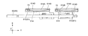
- the lens driving unit 60 includes a frame 61, a connecting unit 62, an intervening unit 63, an ultrasonic motor 64, and a guide unit 80.
- the frame 61 is connected to either one of the supported portions 32B and 33B of the second lens unit 32 and the third lens unit 33 via the connecting portion 62.
- the frame 61 on the-side in the Y direction corresponds to the "first frame” of the present invention
- the frame 61 on the + side in the Y direction corresponds to the "second frame” of the present invention.
- the frame 61 is configured to be movable in the direction of the optical axis O by the guide portion 80 guiding the movement in the direction of the optical axis O (Y direction).
- the second lens unit 32 or the third lens unit 33 connected to the frame 61 via the connecting portion 62 also moves along the support shaft 50. There is.
- the frame 61 has a guided portion 611 and a magnet holding portion 612.
- the guided portion 611 is a portion where the guide portion 80 guides the movement of the frame 61 in the Y direction, and is provided at a position corresponding to the guide portion 80 in the X direction.
- the guided portion 611 has a first portion 611A, a second portion 611B, a third portion 611C, and a fourth portion 611D.
- the first portion 611A is a portion that constitutes the top surface (the surface on the + side in the Z direction) of the frame 61, and is configured to extend in the direction of the optical axis (Y direction).
- the first portion 611A is provided so as to cover the guide portion 80 from the + side in the Z direction.
- a connecting portion 62 is provided on the surface of the first portion 611A on the + side in the Z direction. As shown in FIG. 10, the connecting portion 62 is formed on the + side surface of the frame 61 in the Z direction and in the Y direction of any of the supported portions 32B and 33B of the second lens unit 32 and the third lens unit 33. It is a plate-shaped spring member (elastic member) fixed to the surface on the minus side of the lens. Since the connecting portion 62 is composed of a spring member, even if the positional relationship between the frame 61 and the supported portions 32B and 33B is displaced due to manufacturing tolerances or the like, the displacement of the positional relationship is absorbed by the elastic force of the spring member. Can be done.
- the second portion 611B extends from the negative end of the first portion 611A in the Y direction (one end of the first portion 611A) to the negative side in the Z direction (predetermined direction). This is a portion that supports the first guide shaft 81 and the second guide shaft 82.
- a shaft hole 611E penetrating in the Y direction is formed in the second portion 611B.
- the shaft hole 611E is provided at a position corresponding to the first guide shaft 81 described later, and the first guide shaft 81 is passed through the shaft hole 611E.
- a shaft engaging portion 611F is formed at the end on the-side in the Z direction of the second portion 611B.
- the shaft engaging portion 611F is provided at a position where it can engage with the second guide shaft 82, which will be described later, and engages with the second guide shaft 82 from the + side in the Z direction.
- the third portion 611C is a portion that extends from the + side end of the first portion 611A in the Y direction (the other end of the first portion 611A) to the ⁇ side in the Z direction to support the second guide shaft 82. More specifically, the third portion 611C extends to a position where the end on the ⁇ side in the Z direction has a predetermined distance from the second guide shaft 82.
- a shaft hole 611G penetrating in the Y direction is formed in the third portion 611C.
- the shaft hole 611G is provided at a position corresponding to the first guide shaft 81, and the first guide shaft 81 is passed through the shaft hole 611G.
- the fourth part 611D is a part extending from the + side end of the first part 611A in the X direction.
- the fourth portion 611D is provided over the entire Y direction of the first portion 611A, and is arranged so as to cover the guide portion 80 from the + side in the X direction.
- an absorption unit 613 is provided between the fourth portion 611D and the guide portion 80 (second guide shaft 82).
- the absorbing portion 613 is composed of a spring member and is arranged between the fourth portion 611D and the second guide shaft 82.
- the absorption unit 613 urges the second guide shaft 82 to the ⁇ side in the X direction with respect to the fourth portion 611D. As a result, the absorption unit 613 absorbs the deviation of the positional relationship between the frame 61 and the guide unit 80.
- the magnet holding portion 612 is a portion that holds the magnet portion 614 for position detection, and is from the end of the fourth portion 611D on the ⁇ side in the Z direction to the ⁇ side in the X direction. It is extending.
- a recess 612A is formed at the end of the magnet holding portion 612 on the-side in the Z direction, and the magnet portion 614 is held in the recess.
- a position detection unit 70 is provided at a portion of the housing 10 facing the magnet unit 614.
- the position detection unit 70 is a magnetoresistive element, and detects the position of the frame 61 in the Y direction (direction of the optical axis) by detecting a magnetic field on a surface including the X direction and the Y direction. Details of the magnet unit 614 and position detection by the position detection unit 70 will be described later.
- an intervening portion 63 is provided above the magnet holding portion 612.
- the intervening portion 63 has a first intervening member 631 and a second intervening member 632.
- the first intervening member 631 is composed of, for example, a flat metal member, and is adhered to the surface on the + side of the fourth portion 611D of the frame 61 in the X direction.
- Two protrusions D1 and D2 are provided on the surface of the fourth portion 611D on the + side in the X direction.
- the two protrusions D1 and D2 project from the surface of the fourth portion 611D and are arranged side by side in the Y direction.
- the protrusion D1 is provided near the center of the fourth portion 611D in the Y direction
- the protrusion D2 is provided near the + side end of the fourth portion 611D in the Y direction. ..
- the first intervening member 631 is arranged parallel to the direction of the optical axis (Y direction), and has engaging holes 631A and 631B that engage with the two protrusions D1 and D2.
- the engagement hole 631A is arranged near the central portion of the first intervening member 631 in the Y direction and engages with the protrusion D1.
- the engaging hole 631A is formed to have a size that allows the intervening portion 63 (first intervening member 631) to rotate around the engaging hole 631A to which the protruding portion D1 is engaged and the protrusion D1 is engaged. Has been done.
- the engagement hole 631B is arranged near the + side end of the first intervening member 631 in the Y direction and engages with the protrusion D2.
- the engaging hole 631B is formed in a size that can be engaged with the protrusion D2 and has a distance such that the inner edge of the engaging hole 631B can move with respect to the protrusion D2 (see FIG. 12B).
- the intervening portion 63 is centered on the engaging hole 631A (protrusion D1) within the range of the engaging hole 631B. It becomes possible to rotate in. As a result, the posture of the intervening portion 63 can be adjusted so that the contact portion 632B of the intervening portion 63 is parallel to the guide shaft.
- the second intervening member 632 is composed of, for example, a plate-shaped metal member, and is adhesively fixed to, for example, the first intervening member 631.
- the second intervening member 632 has a main body portion 632A and a contact portion 632B.
- the main body portion 632A has a plane parallel to the direction of the optical axis (Y direction), and is a portion that is adhesively fixed to the first intervening member 631.
- the main body 632A is formed with holes A1 and A2 through which the two protrusions D1 and D2 of the fourth portion 611D of the frame 61 pass.
- the contact portion 632B is a portion where the vibrator of the ultrasonic motor 64 comes into contact with the contact portion 632B, and is configured by bending both ends of the main body portion 632A in the Z direction toward the side opposite to the lens portion.
- the main body portion 632A connecting the pair of contact portions 632B is arranged so as to cover the ultrasonic motor 64 from the X direction ⁇ side, and the contact portion 632B sandwiches the ultrasonic motor 64 (resonant portion 641). Be placed.
- the intervening portion 63 By configuring the intervening portion 63 in this way, a force acts on the contact portion 632B from the vibrator of the ultrasonic motor 64 to generate a thrust in the intervening portion 63 in the direction of the optical axis (Y direction). As a result, it is possible to apply a thrust that moves the intervening portion 63 to the frame 61 in the direction of the optical axis (Y direction).
- a plurality of openings C1, C2, C3, and C4 are formed in the connecting portion 632C between the main body portion 632A and the contact portion 632B.
- a plurality of openings C1, C2, C3, and C4 are arranged side by side in the Y direction on both sides of the connecting portion in the Y direction.
- the two openings C2 and C3 on the center side in the Y direction are longer in the Y direction than the two openings C1 and C4 on both ends in the Y direction.
- the length in the Z direction is long.
- the connecting portion 632C constitutes five connecting portions 632D arranged at intervals in the direction of the optical axis by forming the four openings C1, C2, C3, and C4.
- each connection portion 632D in the Y direction is wider than that of the connection portion 632D located from the center to the outside in the Y direction.
- the middle connecting portion 632D in the Y direction is the narrowest of the five connecting portions 632D.
- the connection portions 632D at both ends in the Y direction are the widest of the five connection portions 632D.
- the connection portion 632D located between the middle connection portion 632D and the connection portions 632D at both ends is wider than the middle connection portion 632D and narrower than the connection portions 632D at both ends.
- the connecting portion 632C becomes weaker as it is located closer to the end, in the present embodiment, in the connecting portion 632C, the size of the openings C1, C2, C3, C4 and the connecting portion 632D By changing the width, the strength of the connecting portion 632C is adjusted.
- the pressing force applied by the vibrator 641B at each position of the contact portion 632B can be equalized in the entire Y direction.
- the stepless optical zoom function is activated, even if the movable portion is moved within a relatively long movement range, the moving force by the intervening portion 63 is stably generated. be able to.
- the ultrasonic motor 64 is a drive source for generating a driving force for moving the frame 61, and the respective arrangement portions 111A of the first wall 111 on the + side in the X direction ( It is fixedly arranged in (see FIG. 3 etc.).
- the ultrasonic motor 64 has a resonance portion 641, a piezoelectric element 642, a first electrode 643, and a second electrode 644.
- the ⁇ side ultrasonic motor 64 in the Y direction corresponds to the “first ultrasonic motor” of the present invention
- the + side ultrasonic motor 64 in the Y direction corresponds to the “second ultrasonic motor” of the present invention. Corresponds to.
- the resonance portion 641 is formed of, for example, a conductive material, resonates with the vibration of the piezoelectric element 642, and converts the vibration motion into the linear motion of the frame 61. Specifically, the resonance portion 641 vibrates in an inclined direction inclined with respect to the direction of the optical axis (Y direction) based on the vibration of the piezoelectric element 642 and presses the intervening portion 63 to press the intervening portion 63. A thrust that moves in the direction of the optical axis is generated in the frame 61 via the frame 61.
- the resonance portion 641 is arranged so as to be sandwiched between the two contact portions 632B in the intervening portion 63. As shown in FIG. 16, the resonance portion 641 has a body portion 641A, two vibrators 641B, a protruding portion 641C, and an energizing portion 641D.
- the body portion 641A is formed, for example, in a substantially rectangular shape, and is a portion sandwiched between the piezoelectric elements 642.
- the two vibrators 641B extend in the Y direction from both ends of the body portion 641A in the Z direction.
- the two vibrators 641B have a symmetrical shape, and their free ends come into contact with the contact portion 632B of the intervening portion 63.
- the two oscillators 641B correspond to the "first oscillator” and the "second oscillator” of the present invention.
- the protruding portion 641C extends from the central portion of the body portion 641A in the Z direction to the + side in the Y direction.
- the energizing portion 641D extends from the central portion of the body portion 641A in the Z direction to the side opposite to the protruding portion 641C (-side in the Y direction).
- the piezoelectric element 642 is, for example, a vibrating element formed of a ceramic material, for example, in a plate shape, and generates vibration by applying a high frequency voltage.
- Two piezoelectric elements 642 are provided, and are arranged so as to sandwich the body portion 641A of the resonance portion 641 in the X direction.
- the first electrode 643 has a sandwiching portion 643A that sandwiches the resonance portion 641 and the piezoelectric element 642, and an electrode portion 643B to which a voltage is applied.
- the first electrode 643 applies a voltage to the piezoelectric element 642 via the sandwiching portion 643A that sandwiches the piezoelectric element 642 or the like.
- the second electrode 644 is electrically connected to the energized portion 641D of the resonance portion 641.
- the first electrode 643 and the second electrode 644 come into contact with the terminal of the terminal portion 111C described above inside the housing 10.
- Two piezoelectric elements 642 are attached to the body portion 641A of the resonance portion 641 and sandwiched between the first electrodes 643, so that they are electrically connected to each other. For example, when one of the feeding paths is connected to the first electrode 643 and the other is connected to the second electrode 644, a voltage is applied to the piezoelectric element 642 and vibration is generated.
- the resonance unit 641 has at least two resonance frequencies and deforms with different behaviors with respect to each resonance frequency.
- the overall shape of the resonant portion 641 is set so that it deforms with different behaviors with respect to the two resonant frequencies.
- the different behaviors are the behavior of moving the frame 61 to the + side in the Y direction via the intervening portion 63 and the behavior of moving the frame 61 to the ⁇ side.
- the resonance portion 641 is arranged so that the vibrator 641B faces any of the pair of contact portions 632B of the intervening portion 63, each contact when the two vibrators 641B are deformed.
- the tip of the vibrator 641B presses the contact portion 632B in a direction inclined with respect to the Y direction from the opposite side of the portion 632B (see arrow A).
- each contact portion 632B When each contact portion 632B is pressed in the direction of arrow A by the tip of the vibrator 641B, a reaction force is generated at each contact portion 632B to return to the vibrator 641B side.
- the intervening portion 63 generates a reaction force in the direction from the outside to the inside of the pair of contact portions 632B based on the contact between each vibrator 641B and the pair of contact portions 632B.
- the reaction force of the intervening portion 63 with respect to the pressing of the vibrator 641B causes the friction generated between the vibrator 641B and the contact portion 632B, and a thrust in the Y direction is generated in the intervening portion 63.
- a thrust (see arrow B) that moves in the Y direction is applied to the frame 61 that is adhered to the intervening portion 63.
- the second lens unit 32 or the third lens unit 33 connected to the frame 61 moves in the Y direction.
- the contact portion 632B is configured to extend in the Y direction, the contact portion 632B is pressed by the vibrator 641B and moves in the Y direction while making contact with the vibrator 641B so as to slide. Therefore, since the contact portion 632B is continuously pressed by the vibrator 641B, the frame 61 bonded to the intervening portion 63 can be continuously moved in the Y direction.
- the pressing direction of the vibrator 641B is the direction of arrow A
- the sliding direction of the contact portion 632B is the direction of arrow B
- the pressing direction of the vibrator 641B is In the direction of arrow C
- the sliding direction of the contact portion 632B is in the direction of arrow D.
- each of the ultrasonic motors 64 provided on the first walls 111 on both sides in the X direction. That is, each ultrasonic motor 64 independently drives each of the second lens unit 32 and the third lens unit 33 in the direction of the optical axis.
- the guide portion 80 is arranged in the region of the fourth wall 114 surrounded by the first wall 111, the second wall 112, and the third wall 113 on the + side in the X direction. That is, the guide portion 80 is arranged on one end side of both ends of the housing 10 that sandwiches the optical axis O in the second lens unit 32 and the third lens unit 33 (see also FIG. 7).
- the first guide portions 80 extend in the direction of the optical axis (Y direction) and are arranged apart from each other so as to support both of the two frames 61 so as to be movable in the direction of the optical axis. It has a guide shaft 81 and a second guide shaft 82.
- the first guide shaft 81 and the second guide shaft 82 are made of, for example, stainless steel, and support the guides of the second wall 112 and the third wall 113 on both end sides (both ends in the X direction) of the optical axis in the housing 10. It is supported by a part (not shown).
- the second wall 112 and the third wall 113 correspond to a "pair of walls" extending from the bottom wall (fourth wall 114) of the present invention.
- the first guide shaft 81 is a guide shaft that guides the movement of the frame 61 by supporting the second portion 611B and the third portion 611C of the guided portion 611 in the frame 61.
- the second guide shaft 82 is arranged parallel to the first guide shaft 81 on the ⁇ side (fourth wall 114 side) in the Z direction of the first guide shaft 81, and is the second portion 611B of the guided portion 611 in the frame 61. It is a guide shaft that guides the movement of the frame 61 by supporting (engaging) the frame 61. Further, the first guide shaft 81 and the second guide shaft 82 are arranged at substantially the same positions as the above-mentioned support shaft 50 in the X direction (see FIG. 10). As described above, the strength of the housing 10 can be improved by providing two guide shafts, the first guide shaft 81 and the second guide shaft 82, for guiding the movement of the lens driving unit 60.
- the second guide shaft 82 is supported by a bearing portion 114A provided on the fourth wall 114.
- the bearing portion 114A is provided between the two frames 61 so as to project from the fourth wall 114 on the + side in the Z direction, and is arranged in a range near the central portion in the Y direction of the second guide shaft 82.
- the second guide shaft 82 is adhesively fixed to the bearing portion 114A. Further, the bearing portion 114A is arranged in a range including the center 82A of the second guide shaft 82 in the X direction (between both ends sandwiching the optical axis) (see FIG. 10).
- the bearing portion 114A is provided at a position where it can come into contact with the second portion 611B of the frame 61. Therefore, when the frame 61 moves to the + side in the Y direction, the second portion 611B of the frame 61 and the bearing portion 114A come into contact with each other (see FIG. 19). As a result, the bearing portion 114A restricts the movement of the frame 61.
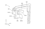
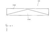
- the magnet portion 614 has a first pole 614A and a second pole 614B arranged adjacent to each other via a boundary 614D in the X direction (width direction orthogonal to the Y direction).
- the first pole 614A is an N-pole magnet
- the second pole 614B is an S-pole magnet. That is, the first pole 614A and the second pole 614B are in the direction in which the magnet unit 614 and the position detection unit 70 face each other (Z direction in the present embodiment) and face the position detection unit 70. As you can see, each is magnetized.
- the first pole 614A and the second pole 614B are arranged in contact with each other. Therefore, the north pole and the south pole are arranged adjacent to each other on the surface 614C facing the position detection unit 70 in the magnet unit 614.
- the magnet unit 614 has a rectangular shape in which the surface 614C facing the position detection unit 70 extends in the Y direction in a state where the first pole 614A and the second pole 614B are in contact with each other. That is, the magnet portion 614 extends linearly along the Y direction with a constant width.
- the adjacent surface of the first pole 614A to the second pole 614B is formed in an arc shape so that the central portion in the Y direction protrudes toward the second pole 614B from both ends in the Y direction.
- the adjacent surface of the second pole 614B to the first pole 614A is configured such that the central portion in the Y direction is recessed from both ends in the Y direction so as to follow the shape of the adjacent surface of the first pole 614A.
- the boundary 614D between the first pole 614A and the second pole 614B is curved (curved in an arc shape) so that the angle formed by the Y direction continuously changes. Specifically, the boundary 614D is displaced from the side of the first pole 614A to the side of the second pole 614B in the X direction as it goes from the end on the ⁇ side of the Y direction to the predetermined position in the magnet portion 614. Further, as the magnet portion 614 moves from the predetermined position to the + side end in the Y direction, the magnet portion 614 bends and extends so as to be displaced from the side of the second pole 614B toward the side of the first pole 614A in the X direction.
- the ratio of the width of the first pole 614A to the width of the second pole 614B is changed by the bending boundary 614D. More specifically, the proportion of the first pole 614A in the first pole 614A and the second pole 614B increases in the Y direction from the negative end of the magnet portion 614 in the Y direction toward a predetermined position. Then, the ratio of the first pole 614A decreases as it goes from the predetermined position to the + side end of the magnet portion 614 in the Y direction.
- the predetermined position is, for example, the central position of the magnet portion 614 in the Y direction. Further, the positions of both ends of the first pole 614A and the second pole 614B in the Y direction in the X direction are the same.
- first pole 614A and the second pole 614B are symmetrically configured on the + side and the-side in the Y direction.
- the distribution of the magnetic force in the magnet portion 614 can be made symmetrical on the + side and the-side with respect to the central portion in the Y direction.
- the magnetic flux density of the magnet unit 614 detected by the position detection unit 70 can be made different depending on the position of the frame 61 (see, for example, FIG. 22).
- the boundary 614D between the first pole 614A and the second pole 614B forms a magnetic field in which the direction of the magnetic flux at the portion of the magnet portion 614 facing the position detection portion 70 changes with the movement of the magnet portion 614. It bends and extends like it does.
- the position detection unit 70 has a magnetic field (magnetic flux density) based on the ratio of N poles and the ratio of S poles in the opposite portion of the magnet unit 614 in the Y direction of the frame 61. It is possible to detect fluctuations according to the movement to.
- the position detection unit 70 faces the + side end portion of the magnet unit 614 in the Y direction.
- the position detection unit 70 faces a portion having a large proportion of the first pole 614A, which is the north pole at the end portion.
- the magnet portion 614 when the frame 61 moves to the + side in the Y direction, the magnet portion 614 also moves together with the frame 61, so that the facing portion of the position detecting portion 70 in the magnet portion 614 changes. As the magnet portion 614 moves toward the central position in the Y direction, the proportion of the first pole 614A increases, so that the proportion of the first pole 614A in the portion facing the position detecting portion 70 gradually increases.
- the portion where the ratio of the first pole 614A (N pole) is maximized becomes the portion facing the position detection unit 70.
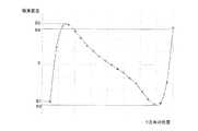
- the position detection unit 70 detects the magnetic flux density at each position in the Y direction of the magnet unit 614.
- the change in the magnetic flux density detected by the position detection unit 70 at this time is, for example, a change as shown in FIG. 22.
- the magnetic flux density sharply increases from B1 on the-side from 0 to B2 on the + side from 0, and then to B3 on the-side from 0. It gradually becomes lower. Then, the magnetic flux density sharply increases from B3 to B4 on the + side of 0.
- the magnetic flux corresponding to each position in the Y direction of the frame 61 can be assigned at approximately even intervals. As a result, it is possible to accurately detect the change in the position of the frame 61 (magnet portion 614) in the Y direction in the Y direction.
- the position detection unit 70 since the magnetic flux density detected by the position detection unit 70 can be made different for each position of the frame 61, the position detection unit 70 can accurately detect the position of the frame 61 in the Y direction. can.
- the position detection unit 70 is a magnetoresistive element, it is possible to detect the magnetic force in the horizontal direction (X direction and Y direction) in the magnet unit 614.
- the position detection unit is a Hall element
- the magnetic force in the vertical direction (Z direction) in the magnet unit is detected. Therefore, for example, if the position of the magnet portion shifts in the X direction due to an assembly error, the magnet portion may deviate from the detection range of the position detection unit and the magnetic force may not be detected, which in turn leads to an accurate position of the frame (movable lens). It may not be possible to detect.
- the position detection unit 70 is a magnetoresistive element
- the detection range of the magnetic force in the horizontal direction can be expanded as compared with the position detection unit of the Hall element.
- the magnetic force in the magnet portion 614 can be detected, and by extension, the accurate position of the frame 61 (movable lens) can be detected. Can be done.
- the distribution of the magnetic force can be made symmetrical accordingly.
- the slope of the change in the magnetic flux density in the position detection unit 70 can be made substantially constant (for example, between B2 and B3 in FIG. 22), so that the change in the magnetic flux density at each position in the Y direction can be made substantially constant. can do.
- the magnetic flux density can be assigned to each position in the Y direction at equal intervals, the position of the frame 61 (movable lens) in the Y direction can be accurately detected by the position detection unit 70.
- the adjacent surfaces of the first pole 614A and the second pole 614B are formed in an arc shape, but the present invention is not limited to this, and for example, as shown in FIG. 23, the first pole
- the adjacent surfaces of the 1st pole 614A and the 2nd pole 614B may be formed in a triangular shape.
- the adjacent surfaces of the first pole 614A and the second pole 614B may be formed in a staircase shape.
- the first pole 614A and the second pole 614B have symmetrical shapes on both sides in the Y direction, but the present invention is not limited to this, and for example, as shown in FIG. 25, the first pole The pole 614A and the second pole 614B do not have to be symmetrical on both sides in the Y direction.
- FIG. 25 shows that the adjacent surfaces of the first pole 614A and the second pole 614B have a triangular shape.
- the apex position (predetermined position) on the adjacent surface of the first pole 614A is a position shifted to the + side in the Y direction from the central portion in the Y direction of the magnet portion 614.
- the apex position (predetermined position) on the adjacent surface of the first pole 614A is the central portion in the Y direction, and both ends in the Y direction on the adjacent surface of the first pole 614A are in the X direction.
- the positions may be different from each other.
- the position detection unit 70 detects the magnetic flux density of the magnet unit 614, but the present invention is not limited to this.
- the position detection unit 70 may detect the rotation angle of the magnet unit 614 around the Z direction.
- one position detection unit 70 is provided for each frame 61, but the present invention is not limited to this.
- the configuration may include a plurality of position detection units 70 arranged side by side in the direction of the optical axis (Y direction). By doing so, the accuracy of position detection of the frame 61 can be further improved.
- the position detecting unit 70 is a magnetoresistive element, but the present invention is not limited to this, and as long as the magnetic field on the surface including the X direction and the Y direction can be detected, how is it? It may be anything.
- the configuration has two guide shafts, but the present invention is not limited to this, and for example, a configuration having three or more guide shafts may be used, or one guide shaft may be provided. It may have a configuration having.
- the support shafts 50 are provided on both sides in the X direction, but the present invention is not limited to this, and the support shafts 50 may be provided on only one side in the X direction.
- the side wall portion 11 and the bottom wall portion 12 of the housing 10 are insert-molded, but the present invention is not limited to this, and the bottom wall portion is adhered to the side wall portion 11. It may be something like fixing.
- the configuration has two movable lenses composed of the second lens unit 32 and the third lens unit 33, but the present invention is not limited to this, and the present invention is not limited to this, and three or more movable lenses. It may have a structure having one movable lens, or it may have a structure having one movable lens.
- the configuration has four lens units, but the present invention is not limited to this, and as long as the configuration has at least one movable lens, a number of lens units are provided. Is also good. Further, in the case of the configuration having one movable lens, the lens driving unit is also one.
- the intervening portion 63 is formed by bending a plate-shaped metal member, but the present invention is not limited to this, and the main body portion and the contact portion constituting the intervening portion are formed. It may be composed of different members.
- the frame 61 and the intervening portion 63 are composed of separate members, but the present invention is not limited to this.
- the frame 61 and the intervening portion 63 may be integrally configured. That is, the lens driving unit may have a moving unit that moves in the direction of the optical axis according to the resonance of the resonance unit and is connected to each lens unit so as to transmit the movement in the direction of the optical axis.
- the connecting portion 62 connecting the frame 61 and the lens unit is composed of a spring member, but the present invention is not limited to this, and any member as long as it is an elastic member. It may be composed of members.
- the third portion 611C of the frame 61 is arranged at a distance from the second guide shaft 82, but the present invention is not limited to this, and the third portion is the second guide shaft. It may be a configuration that also supports.
- the bottom wall portion has a bent portion and a half punch, but the present invention is not limited to this, and a configuration having no bent portion and a half punch may be used.
- the resonance portion 641 has a configuration having two vibrators 641B, but the present invention is not limited to this, and for example, a configuration having one vibrator may be used.
- the drive control unit, the reflection drive control unit, and the image pickup control unit are separately provided, but the present invention is not limited to this, and the drive control unit, the reflection drive control unit, and the image pickup control unit are provided. At least two of them may be composed of one control unit.
- the bearing portion 114A is provided, but the present invention is not limited to this, and the bearing portion may not be provided.
- the absorption unit 613 is provided, but the present invention is not limited to this, and the absorption unit may not be provided.
- a smartphone which is a mobile terminal with a camera
- a camera-mounted device including the camera module 1 has been described as an example of a camera-mounted device including the camera module 1.
- the present invention has described the images obtained by the camera module and the camera module. It can be applied to a camera-mounted device having an image processing unit that processes information.
- Camera-mounted devices include information devices and transportation devices.
- the information device includes, for example, a mobile phone with a camera, a notebook computer, a tablet terminal, a portable game machine, a web camera, a drone, and an in-vehicle device with a camera (for example, a back monitor device and a drive recorder device).
- Transportation equipment also includes, for example, automobiles and drones.
- 29A and 29B are diagrams showing an automobile V as a camera-mounted device on which an in-vehicle camera module VC (Vehicle Camera) is mounted.
- 29A is a front view of the automobile V
- FIG. 29B is a rear perspective view of the automobile V.
- the automobile V is equipped with the camera module 1 described in the embodiment as the in-vehicle camera module VC.
- the vehicle-mounted camera module VC may be attached to the windshield toward the front or attached to the rear gate toward the rear, for example.
- This in-vehicle camera module VC is used for a back monitor, a drive recorder, a collision avoidance control, an automatic driving control, and the like.
- the above embodiments are merely examples of embodiment of the present invention, and the technical scope of the present invention should not be construed in a limited manner by these. That is, the present invention can be implemented in various forms without departing from its gist or its main features. For example, the shape, size, number, and material of each part described in the above embodiment are merely examples, and can be changed as appropriate.
- the lens driving device is useful as a lens driving device, a camera module, and a camera-mounted device capable of accurately detecting the position of a movable lens.
- Imaging part 10 Housing 11 Side wall 12 Bottom wall 20 Reflective drive 21 Reflective housing 22 Mirror 23 Reflective drive control 30 Lens 31 1st lens unit 32 2nd lens unit 32A Main body 32B Supported part 33 3 Lens unit 33A Main body 33B Supported part 34 4th lens unit 34A Convex part 40 Imaging part 50 Supporting shaft 60 Lens driving part 61 Frame 62 Connection part 63 Intervening part 64 Ultrasonic motor 70 Position detection part 80 Guide part 81 1st Guide shaft 82 2nd guide shaft 100 Drive control unit 111 1st wall 111A Arrangement part 111B Engagement part 111C Terminal part 112 2nd wall 112A Support part 112B Arrangement part 112C Guide support part 112D Opening part 113 3rd wall 113A Bridge part 113B Support part 113C Guide support part 114 4th wall 114A Bearing part 121 Positioning part 122 Bending part 123 Half punch 200 Imaging control part 611 Guided part 611A 1st part 611B 2nd part 611C 3rd part 611D 4
Abstract
This lens driving device is provided with a movable part, a driving part, a magnet part having a first pole and a second pole, and a position detection part that is disposed to face the magnet part, and detects the position of the magnet part by detecting a magnetic field on a plane including an optical axis direction and a width direction. A boundary extends while bending such that the angle formed with the optical axis direction changes.
Description
本発明は、レンズ駆動装置、カメラモジュールおよびカメラ搭載装置に関する。
The present invention relates to a lens driving device, a camera module, and a camera mounting device.
従来、スマートフォン等の薄型のカメラ搭載装置に搭載されたカメラモジュールが知られている。このようなカメラモジュールは、被写体像の拡大または縮小を行うズーム機能を有するレンズ駆動装置を備えたものが知られている。
Conventionally, a camera module mounted on a thin camera-mounted device such as a smartphone is known. Such a camera module is known to include a lens driving device having a zoom function for enlarging or reducing a subject image.
例えば、特許文献1には、被写体からの光が入射される固定レンズと、固定レンズにより屈曲した光が入射される2つの可動レンズと、2つの可動レンズを光軸の方向に移動させるレンズ駆動部とを備えた構成が開示されている。
For example, Patent Document 1 describes a fixed lens in which light from a subject is incident, two movable lenses in which light bent by the fixed lens is incident, and a lens drive that moves the two movable lenses in the direction of the optical axis. A configuration including a part is disclosed.
このようなレンズ駆動装置においては、光軸の方向における可動レンズの位置を検出するために、可動レンズが設けられる可動部にマグネット部と、マグネット部の磁束を検出する位置検出部(例えば、ホール素子)とが設けられる。マグネット部は、例えば異なる2つの極(N極とS極)が隣接して配置されており、位置検出部との対向部分における磁力が可動レンズの位置に応じて変化するように配置される。
In such a lens driving device, in order to detect the position of the movable lens in the direction of the optical axis, a magnet portion is provided in the movable portion provided with the movable lens, and a position detecting portion (for example, a hole) for detecting the magnetic flux of the magnet portion. Element) and. In the magnet portion, for example, two different poles (N pole and S pole) are arranged adjacent to each other, and the magnetic force at the portion facing the position detection portion is arranged so as to change according to the position of the movable lens.
しかしながら、例えば小型のカメラ搭載装置において、異なる2つの極の対向方向における、マグネット部の位置が組付け誤差等により所望の位置からずれると、位置検出部との位置関係もずれるので、正確に可動レンズの位置検出ができなくなるおそれがあった。
However, for example, in a small camera-mounted device, if the position of the magnet portion deviates from the desired position due to an assembly error or the like in the opposite directions of the two different poles, the positional relationship with the position detection portion also deviates, so that the magnet unit can move accurately. There was a risk that the position of the lens could not be detected.
本発明の目的は、可動レンズの位置検出を正確に行うことが可能なレンズ駆動装置、カメラモジュールおよびカメラ搭載装置を提供することである。
An object of the present invention is to provide a lens driving device, a camera module, and a camera mounting device capable of accurately detecting the position of a movable lens.
本発明に係るレンズ駆動装置は、
光軸の方向に配置され、可動レンズを保持可能な可動部と、
前記可動部を前記光軸の方向に駆動する駆動部と、
前記可動部に設けられ、前記光軸の方向に延び、前記光軸の方向に対し直交する幅方向において境界を介して隣接して配置された第1極および第2極を有するマグネット部と、
前記マグネット部に対向して配置され、前記光軸の方向および前記幅方向を含む面における磁界を検知することにより、前記マグネット部の位置を検出する位置検出部と、
を備え、
前記境界は、前記光軸の方向となす角度が変化するよう曲がって延びる。 The lens driving device according to the present invention is
A movable part that is arranged in the direction of the optical axis and can hold a movable lens,
A drive unit that drives the movable unit in the direction of the optical axis,
A magnet portion provided on the movable portion, extending in the direction of the optical axis, and having a first pole and a second pole adjacent to each other across a boundary in a width direction orthogonal to the direction of the optical axis.
A position detection unit that is arranged to face the magnet unit and detects the position of the magnet unit by detecting a magnetic field on a surface including the direction of the optical axis and the width direction.
With
The boundary bends and extends so that the angle formed with the direction of the optical axis changes.
本発明に係るカメラモジュールは、
上記のレンズ駆動装置と、
前記可動部に保持される前記可動レンズを含むレンズ部と、
前記レンズ部により結像された被写体像を撮像する撮像部と、
を備え、
前記可動レンズを前記光軸の方向に駆動する。 The camera module according to the present invention
With the above lens drive
A lens portion including the movable lens held by the movable portion and
An imaging unit that captures a subject image imaged by the lens unit, and an imaging unit.
With
The movable lens is driven in the direction of the optical axis.
本発明に係るカメラ搭載装置は、
情報機器または輸送機器であるカメラ搭載装置であって、
上記のカメラモジュールと、
前記カメラモジュールで得られた画像情報を処理する撮像制御部と、
を備える。 The camera-mounted device according to the present invention
A camera-mounted device that is an information device or a transportation device.
With the above camera module
An image pickup control unit that processes the image information obtained by the camera module, and
To be equipped.
本発明によれば、可動レンズの位置検出を正確に行うことができる。
According to the present invention, the position of the movable lens can be accurately detected.
以下、本発明の実施の形態を図面に基づいて詳細に説明する。図1は、本発明の実施の形態に係るカメラモジュール1を簡易的に示す図である。図2は、本実施の形態に係るカメラモジュール1を側面視した構成を簡易的に示す図である。
Hereinafter, embodiments of the present invention will be described in detail with reference to the drawings. FIG. 1 is a diagram simply showing a camera module 1 according to an embodiment of the present invention. FIG. 2 is a diagram simply showing a configuration in which the camera module 1 according to the present embodiment is viewed from the side.
カメラモジュール1は、例えばスマートフォンM(図28A、図28B参照)、携帯電話機、デジタルカメラ、ノート型パソコン、タブレット端末、携帯型ゲーム機、車載カメラなどの薄型のカメラ搭載装置に搭載される。
The camera module 1 is mounted on a thin camera-mounted device such as a smartphone M (see FIGS. 28A and 28B), a mobile phone, a digital camera, a notebook computer, a tablet terminal, a portable game machine, and an in-vehicle camera.
本実施の形態のカメラモジュール1の構造を説明するにあたり、直交座標系(X,Y,Z)を使用する。後述する図においても共通の直交座標系(X,Y,Z)で示している。カメラモジュール1は、カメラ搭載装置で実際に撮影が行われる場合に、例えばX方向が左右方向、Y方向が上下方向、Z方向が前後方向となるように搭載される。被写体からの光は、Z方向-側(マイナス側)から入射し、屈曲してY方向+側(プラス側)へと導光される。カメラモジュール1のZ方向の厚さを薄くすることにより、カメラ搭載装置の薄型化を図ることができる。
In explaining the structure of the camera module 1 of the present embodiment, a Cartesian coordinate system (X, Y, Z) is used. Also in the figure described later, it is shown by a common Cartesian coordinate system (X, Y, Z). The camera module 1 is mounted so that, for example, the X direction is the left-right direction, the Y direction is the up-down direction, and the Z direction is the front-back direction when shooting is actually performed by the camera-mounted device. The light from the subject is incident from the-side (minus side) in the Z direction, bends, and is guided to the + side (plus side) in the Y direction. By reducing the thickness of the camera module 1 in the Z direction, the thickness of the camera mounting device can be reduced.
図1に示すように、カメラモジュール1は、筐体10と、反射駆動部20と、レンズ部30と、撮像部40と、支持軸50(図3参照)と、レンズ駆動部60(図5参照)と、位置検出部70(図10参照)と、駆動制御部100とを備える。
As shown in FIG. 1, the camera module 1 includes a housing 10, a reflection drive unit 20, a lens unit 30, an image pickup unit 40, a support shaft 50 (see FIG. 3), and a lens drive unit 60 (FIG. 5). (See), a position detection unit 70 (see FIG. 10), and a drive control unit 100.
駆動制御部100は、CPU(Central Processing Unit)、ROM(Read Only Memory)、RAM(Random Access Memory)等を備える。CPUは、ROMから処理内容に応じたプログラムを読み出してRAMに展開し、展開したプログラムと協働してレンズ駆動部60を集中制御する。これにより、駆動制御部100は、筐体10に収容されるレンズ部30の後述する第2レンズユニット32および第3レンズユニット33をY方向(光軸の方向)に駆動する。その結果、カメラモジュール1は、無段階光学ズームおよびオートフォーカスを行う。筐体10、支持軸50、レンズ駆動部60、位置検出部70および駆動制御部100は、本発明の「レンズ駆動装置」に対応する。
The drive control unit 100 includes a CPU (Central Processing Unit), a ROM (Read Only Memory), a RAM (Random Access Memory), and the like. The CPU reads a program according to the processing content from the ROM, develops it in the RAM, and centrally controls the lens driving unit 60 in cooperation with the expanded program. As a result, the drive control unit 100 drives the second lens unit 32 and the third lens unit 33, which will be described later, of the lens unit 30 housed in the housing 10 in the Y direction (direction of the optical axis). As a result, the camera module 1 performs stepless optical zoom and autofocus. The housing 10, the support shaft 50, the lens drive unit 60, the position detection unit 70, and the drive control unit 100 correspond to the "lens drive device" of the present invention.
また、図2に示すように、カメラモジュール1では、入射光L1が反射駆動部20を介して筐体10に入射される。反射駆動部20は、反射筐体21、ミラー22および反射駆動制御部23を有する。図1および図2に示す例では、反射筐体21は、筐体10のY方向の-側の端部と隣接して配置されている。ミラー22は、反射筐体21内に設けられ、入射光L1を反射光L2として筐体10に向けて反射する。反射駆動制御部23は、CPU、ROM、RAM等を備えており、ミラー22の向きを制御する。
Further, as shown in FIG. 2, in the camera module 1, the incident light L1 is incident on the housing 10 via the reflection drive unit 20. The reflection drive unit 20 includes a reflection housing 21, a mirror 22, and a reflection drive control unit 23. In the examples shown in FIGS. 1 and 2, the reflective housing 21 is arranged adjacent to the negative end of the housing 10 in the Y direction. The mirror 22 is provided in the reflective housing 21, and reflects the incident light L1 as the reflected light L2 toward the housing 10. The reflection drive control unit 23 includes a CPU, ROM, RAM, and the like, and controls the orientation of the mirror 22.
また、本実施の形態に係るミラー22は、X方向およびY方向に延びる2つの回転軸(不図示)を有している。反射駆動部20では、反射駆動制御部23の制御の下、当該回転軸を中心にミラー22が回転する。これにより、カメラモジュール1は、撮影時に生じる振れ(振動)を光学的に補正して画像の乱れを軽減する振れ補正機能(OIS(Optical Image Stabilization)機能)を有する。
Further, the mirror 22 according to the present embodiment has two rotation axes (not shown) extending in the X direction and the Y direction. In the reflection drive unit 20, the mirror 22 rotates around the rotation axis under the control of the reflection drive control unit 23. As a result, the camera module 1 has a shake correction function (OIS (Optical Image Stabilization) function) that optically corrects shake (vibration) that occurs during shooting to reduce image distortion.
筐体10内に入射した反射光L2は、筐体10内に収容されるレンズ部30を介して撮像部40に出力される。
The reflected light L2 incident on the housing 10 is output to the imaging unit 40 via the lens unit 30 housed in the housing 10.
撮像部40は、筐体10のY方向の+側の外側面(後述する第2壁112の配置部112B)に配置されており、レンズ部30を介して反射光L2が入射するように構成されている。撮像部40は、撮像素子および基板等(不図示)を有する。
The image pickup unit 40 is arranged on the outer surface of the housing 10 on the + side in the Y direction (arrangement portion 112B of the second wall 112 described later), and is configured such that the reflected light L2 is incident through the lens portion 30. Has been done. The image pickup unit 40 includes an image pickup device, a substrate, and the like (not shown).
撮像素子は、例えばCCD(Charge Coupled Device)型イメージセンサ、CMOS(Complementary Metal Oxide Semiconductor)型イメージセンサ等により構成される。撮像素子は、基板に実装され、ボンディングワイヤーを介して基板上の配線に電気的に接続される。撮像素子は、レンズ部30により結像された被写体像を撮像し、被写体像に対応する電気信号を出力する。
The image sensor is composed of, for example, a CCD (Charge Coupled Device) type image sensor, a CMOS (Complementary Metal Oxide Semiconductor) type image sensor, or the like. The image sensor is mounted on the substrate and is electrically connected to the wiring on the substrate via the bonding wire. The image sensor captures the subject image formed by the lens unit 30 and outputs an electric signal corresponding to the subject image.
また、撮像部40の基板には、プリント配線基板(不図示)が電気的に接続され、このプリント配線基板を介して撮像素子への給電および撮像素子で撮像された被写体像の電気信号の出力が行われる。当該電気信号は、カメラ搭載装置に設けられる撮像制御部200に出力される。撮像制御部200は、CPU、ROM、RAM等を備えており、カメラモジュール1で得られた画像情報を処理する。撮像制御部200は、カメラ搭載装置に搭載されていれば良いが、カメラモジュール1に内蔵されていても良い。
A printed wiring board (not shown) is electrically connected to the substrate of the image pickup unit 40, and power is supplied to the image sensor via the printed wiring board and an electric signal of the subject image captured by the image sensor is output. Is done. The electric signal is output to the image pickup control unit 200 provided in the camera-mounted device. The image pickup control unit 200 includes a CPU, a ROM, a RAM, and the like, and processes the image information obtained by the camera module 1. The image pickup control unit 200 may be mounted on the camera mounting device, but may be mounted on the camera module 1.
図3に示すように、筐体10は、レンズ部30、支持軸50およびレンズ駆動部60(図5も参照)を収容しており、例えば全体として直方体形状を有する。筐体10は、側壁部11と、底壁部12とを有する。
As shown in FIG. 3, the housing 10 houses the lens portion 30, the support shaft 50, and the lens driving portion 60 (see also FIG. 5), and has, for example, a rectangular parallelepiped shape as a whole. The housing 10 has a side wall portion 11 and a bottom wall portion 12.
側壁部11は、Y方向-側に開口する部分を有する、例えば樹脂製の壁部であり、第1壁111、第2壁112、第3壁113および第4壁114を有する(図7等も参照)。
The side wall portion 11 is, for example, a resin wall portion having a portion that opens in the Y direction − side, and has a first wall 111, a second wall 112, a third wall 113, and a fourth wall 114 (FIG. 7, etc.). See also).
第1壁111は、Y方向に延びて構成され、X方向の両側において一対設けられている。一対の第1壁111のうち、X方向の+側の第1壁111における筐体10の内側面には、後述する超音波モータが配置される配置部111Aが設けられている。配置部111Aは、X方向の+側の第1壁111においてY方向の中央部の両側にそれぞれ設けられている。
The first wall 111 is configured to extend in the Y direction, and is provided in pairs on both sides in the X direction. Of the pair of first walls 111, an arrangement portion 111A on which an ultrasonic motor, which will be described later, is arranged is provided on the inner surface of the housing 10 on the first wall 111 on the + side in the X direction. The arrangement portions 111A are provided on both sides of the central portion in the Y direction on the first wall 111 on the + side in the X direction.
また、図4に示すように、X方向の+側の第1壁111には、端子部111Cが設けられている。端子部111Cは、例えば第1壁111と底壁部12との間に形成された隙間を介して筐体10の内外にわたって配置される端子(不図示)を有する。当該端子の筐体10の外側に配置された部分は、カメラ搭載装置の所定の配線と接続される。
Further, as shown in FIG. 4, a terminal portion 111C is provided on the first wall 111 on the + side in the X direction. The terminal portion 111C has terminals (not shown) arranged inside and outside the housing 10 through, for example, a gap formed between the first wall 111 and the bottom wall portion 12. The portion of the terminal arranged outside the housing 10 is connected to a predetermined wiring of the camera-mounted device.
また、第1壁111の底面(Z方向の-側の面)には、底壁部12の位置決め部121が係合する被係合部111Bが形成されている。
Further, on the bottom surface (the surface on the − side in the Z direction) of the first wall 111, an engaged portion 111B with which the positioning portion 121 of the bottom wall portion 12 is engaged is formed.
図3および図4に示すように、第2壁112は、X方向に延びて構成され、一対の第1壁111のY方向の+側の端部を接続するように設けられている。また、第2壁112における天面(Z方向の+側の面)の部分には、支持軸50を支持する支持部112AがX方向の両側にそれぞれ設けられている。第2壁112の外側面には、撮像部40が配置される配置部112Bが設けられている。
As shown in FIGS. 3 and 4, the second wall 112 is configured to extend in the X direction and is provided so as to connect the + side ends of the pair of first walls 111 in the Y direction. Further, support portions 112A for supporting the support shaft 50 are provided on both sides in the X direction on the top surface (the surface on the + side in the Z direction) of the second wall 112. On the outer surface of the second wall 112, an arrangement portion 112B on which the imaging unit 40 is arranged is provided.
また、第2壁112の配置部112B内には、ガイド支持部112Cおよび開口部112Dが設けられている。本実施の形態では、ガイド支持部112Cは、後述するガイド軸81,82を支持する孔であり、配置部112B内における開口部112DよりもX方向の-側に設けられている。ガイド支持部112Cは、Z方向に並んで2つ設けられている。開口部112Dは、レンズ部30の第4レンズユニット34が嵌合する開口であり、配置部112B内におけるX方向の中央部に設けられている。
Further, a guide support portion 112C and an opening 112D are provided in the arrangement portion 112B of the second wall 112. In the present embodiment, the guide support portion 112C is a hole for supporting the guide shafts 81 and 82 described later, and is provided on the − side in the X direction with respect to the opening 112D in the arrangement portion 112B. Two guide support portions 112C are provided side by side in the Z direction. The opening 112D is an opening into which the fourth lens unit 34 of the lens portion 30 fits, and is provided at the central portion in the X direction in the arrangement portion 112B.
図3および図5に示すように、第3壁113は、一対の第1壁111のY方向の-側の端部のそれぞれに設けられている。一対の第3壁113は、第1壁111と第2壁112とで構成される空間を囲うように、それぞれ設けられる。一対の第3壁113の間には、レンズ部30の第1レンズユニット31が入り込める程度の間隔があけられており、各第3壁113のZ方向の-側の端部を架橋する架橋部113Aが設けられている。
As shown in FIGS. 3 and 5, the third wall 113 is provided at each of the negative end portions of the pair of first walls 111 in the Y direction. The pair of third walls 113 are provided so as to surround the space composed of the first wall 111 and the second wall 112, respectively. The pair of third walls 113 are spaced apart from each other so that the first lens unit 31 of the lens portion 30 can enter, and a cross-linking portion that bridges the negative end portion of each third wall 113 in the Z direction. 113A is provided.
また、一対の第3壁113の天面(Z方向の+側の面)には、支持軸50を支持する支持部113Bが設けられている。一対の第3壁113のZ方向の中央部付近には、後述するガイド軸81,82を支持するガイド支持部113Cが設けられている。
Further, a support portion 113B for supporting the support shaft 50 is provided on the top surface (the surface on the + side in the Z direction) of the pair of third walls 113. A guide support portion 113C for supporting the guide shafts 81 and 82, which will be described later, is provided near the central portion of the pair of third walls 113 in the Z direction.
ガイド支持部113Cは、Z方向の長さが、上述した第2壁112における2つのガイド支持部112Cの配置範囲に対応する長さで構成された長孔である。ガイド支持部113Cは、第2壁112における2つのガイド支持部112Cのそれぞれに支持されたガイド軸81,82を支持可能となっている。
The guide support portion 113C is a long hole having a length in the Z direction corresponding to the arrangement range of the two guide support portions 112C on the second wall 112 described above. The guide support portion 113C can support the guide shafts 81 and 82 supported by the two guide support portions 112C on the second wall 112, respectively.
図5に示すように、第4壁114は、各第1壁111、第1壁111に対応する第3壁113および第2壁112で構成される空間の底壁を構成しており、X方向において第3壁113に対応する領域に設けられている(図7も参照)。そのため、X方向の両側の第4壁114の間には、間隔があけられている。
As shown in FIG. 5, the fourth wall 114 constitutes the bottom wall of the space composed of the first wall 111, the third wall 113 corresponding to the first wall 111, and the second wall 112, respectively. It is provided in the area corresponding to the third wall 113 in the direction (see also FIG. 7). Therefore, there is a gap between the fourth walls 114 on both sides in the X direction.
図4~図6に示すように、底壁部12は、筐体10の底壁を構成する例えば略矩形状の金属板であり、X方向の両側の第4壁114および一対の第1壁111を架橋するように設けられている。底壁部12は、インサート成形により、一対の第1壁111の底部を含む側壁部11の底面部分と一体化されている。また、第1レンズユニット31に対応する部分に底壁部12の部分が存在しないように、底壁部12のY方向の-側の端部の部分が切り欠かれている。
As shown in FIGS. 4 to 6, the bottom wall portion 12 is, for example, a substantially rectangular metal plate constituting the bottom wall of the housing 10, and the fourth wall 114 and the pair of first walls on both sides in the X direction. It is provided so as to bridge 111. The bottom wall portion 12 is integrated with the bottom surface portion of the side wall portion 11 including the bottom portion of the pair of first walls 111 by insert molding. Further, the end portion of the bottom wall portion 12 on the − side in the Y direction is cut out so that the portion of the bottom wall portion 12 does not exist in the portion corresponding to the first lens unit 31.
底壁部12のX方向の両側端には、位置決め部121が設けられている。位置決め部121は、底壁部12の両側端から突出して設けられており、上述した第1壁111の被係合部111Bと係合する。これにより、底壁部12のY方向における位置決めを行うことができる。
Positioning portions 121 are provided at both ends of the bottom wall portion 12 in the X direction. The positioning portion 121 is provided so as to project from both side ends of the bottom wall portion 12, and engages with the engaged portion 111B of the first wall 111 described above. As a result, the bottom wall portion 12 can be positioned in the Y direction.
また、図6に示すように、底壁部12におけるX方向およびY方向の側端には、折り曲げ部122が設けられている。折り曲げ部122は、当該側端をZ方向の+側に折り曲げることにより設けられる。
Further, as shown in FIG. 6, bent portions 122 are provided at the side ends of the bottom wall portion 12 in the X direction and the Y direction. The bent portion 122 is provided by bending the side end to the + side in the Z direction.
また、筐体10の折り曲げ部122に対応する部分には、折り曲げ部122が入り込む溝(不図示)が形成されている。この溝に折り曲げ部122が入り込むことにより、底壁部12が筐体10に固定される。
Further, a groove (not shown) into which the bent portion 122 enters is formed in the portion of the housing 10 corresponding to the bent portion 122. By inserting the bent portion 122 into this groove, the bottom wall portion 12 is fixed to the housing 10.
また、底壁部12の面には、Y方向に並ぶ複数のハーフパンチ123が形成されている。ハーフパンチ123は、底壁部12のX方向にわたって設けられている。本実施の形態では、合計6つのハーフパンチ123が設けられている。
Further, a plurality of half punches 123 arranged in the Y direction are formed on the surface of the bottom wall portion 12. The half punch 123 is provided over the bottom wall portion 12 in the X direction. In this embodiment, a total of six half punches 123 are provided.
このようにハーフパンチ123を設けることにより、筐体10の底壁部分の強度を向上させることができる。
By providing the half punch 123 in this way, the strength of the bottom wall portion of the housing 10 can be improved.
図3および図5に示すように、レンズ部30は、反射駆動部20からの反射光L2(図2参照)が通過する領域を含む、一対の第1壁111で挟まれた領域に設けられている。レンズ部30は、Y方向に並んで配置された第1レンズユニット31、第2レンズユニット32、第3レンズユニット33および第4レンズユニット34を有する。
As shown in FIGS. 3 and 5, the lens unit 30 is provided in a region sandwiched between the pair of first walls 111, including a region through which the reflected light L2 (see FIG. 2) from the reflection drive unit 20 passes. ing. The lens unit 30 has a first lens unit 31, a second lens unit 32, a third lens unit 33, and a fourth lens unit 34 arranged side by side in the Y direction.
第1レンズユニット31は、反射光L2の入射方向(Y方向の+側に向かう方向)の最上流側に配置され、筐体10における一対の第3壁113の間に固定される。
The first lens unit 31 is arranged on the most upstream side of the reflected light L2 in the incident direction (direction toward the + side in the Y direction), and is fixed between the pair of third walls 113 in the housing 10.
第1レンズユニット31の側面は、例えばZ方向の中央部分が凸になるように湾曲して構成されて構成されている。第3壁113の第1レンズユニット31側の側面は、例えば、第1レンズユニット31の側面に沿う形状を有しており、第1レンズユニット31の湾曲部分が嵌まるように構成されている。これにより、第1レンズユニット31が一対の第3壁113の間に固定される。
The side surface of the first lens unit 31 is configured to be curved so that the central portion in the Z direction is convex, for example. The side surface of the third wall 113 on the first lens unit 31 side has, for example, a shape along the side surface of the first lens unit 31, and is configured to fit the curved portion of the first lens unit 31. .. As a result, the first lens unit 31 is fixed between the pair of third walls 113.
第2レンズユニット32は、入射方向において第1レンズユニット31よりも下流側に配置されており、本体部32Aおよび被支持部32Bを有する。第3レンズユニット33は、入射方向において第2レンズユニット32よりも下流側に配置されており、本体部33Aおよび被支持部33Bを有する。第2レンズユニット32は、本発明の「第1の可動部」に対応し、第3レンズユニット33は、本発明の「第2の可動部」に対応する。
The second lens unit 32 is arranged on the downstream side of the first lens unit 31 in the incident direction, and has a main body portion 32A and a supported portion 32B. The third lens unit 33 is arranged on the downstream side of the second lens unit 32 in the incident direction, and has a main body portion 33A and a supported portion 33B. The second lens unit 32 corresponds to the "first movable portion" of the present invention, and the third lens unit 33 corresponds to the "second movable portion" of the present invention.
各本体部32A,33Aは、第1レンズユニット31を通過した光が通るレンズを保持する部分である。被支持部32B,33Bは、支持軸50に移動可能に支持される部分であり、各本体部32A,33AのX方向の両側にそれぞれ設けられている。
The main body portions 32A and 33A are portions for holding the lens through which the light passing through the first lens unit 31 passes. The supported portions 32B and 33B are portions that are movably supported by the support shaft 50, and are provided on both sides of the main body portions 32A and 33A in the X direction, respectively.
第2レンズユニット32の本体部32Aに含まれるレンズは、本発明の「第1の可動レンズ」に対応する。第3レンズユニット33の本体部33Aに含まれるレンズは、本発明の「第2の可動レンズ」に対応する。
The lens included in the main body 32A of the second lens unit 32 corresponds to the "first movable lens" of the present invention. The lens included in the main body 33A of the third lens unit 33 corresponds to the "second movable lens" of the present invention.
第4レンズユニット34は、入射方向の最下流側に配置されており、レンズを含んで構成されている。第4レンズユニット34は、筐体10の第2壁112に隣接する位置において、支持軸50に支持されている。また、図4に示すように、本実施の形態では、第4レンズユニット34のY方向の+側の面には、凸部34Aが設けられている。
The fourth lens unit 34 is arranged on the most downstream side in the incident direction, and includes a lens. The fourth lens unit 34 is supported by the support shaft 50 at a position adjacent to the second wall 112 of the housing 10. Further, as shown in FIG. 4, in the present embodiment, the convex portion 34A is provided on the + side surface of the fourth lens unit 34 in the Y direction.
なお、第1~第4レンズユニット31~34におけるレンズは、レンズ駆動装置の製造時に筐体10に組み付けられても良いし、レンズ駆動装置からカメラモジュール1を製造する際に筐体10に組み付けられても良い。
The lenses in the first to fourth lens units 31 to 34 may be assembled to the housing 10 when the lens driving device is manufactured, or may be assembled to the housing 10 when the camera module 1 is manufactured from the lens driving device. May be done.
凸部34Aは、第2壁112の開口部112Dに嵌合可能な大きさを有している。この凸部34Aが開口部112Dに嵌合することで、第4レンズユニット34が筐体10に固定される。
The convex portion 34A has a size that can be fitted into the opening 112D of the second wall 112. The fourth lens unit 34 is fixed to the housing 10 by fitting the convex portion 34A to the opening 112D.
図3および図5に示すように、支持軸50は、例えばステンレス等で構成されている。支持軸50は、Y方向に延びており、一対の第3壁113の領域のそれぞれに設けられている。各支持軸50は、本実施の形態では互いに等しい長さで構成されており、第3壁113の支持部113Bと第2壁112の各支持部112Aとに支持されている。
As shown in FIGS. 3 and 5, the support shaft 50 is made of, for example, stainless steel. The support shaft 50 extends in the Y direction and is provided in each of the regions of the pair of third walls 113. Each support shaft 50 is configured to have the same length as each other in the present embodiment, and is supported by the support portion 113B of the third wall 113 and each support portion 112A of the second wall 112.
レンズ駆動部60は、第2レンズユニット32および第3レンズユニット33のそれぞれに対応して設けられ、上述の駆動制御部100の制御の下、対応する第2レンズユニット32および第3レンズユニット33の何れかを独立して移動させる。レンズ駆動部60は、X方向の+側における、第1壁111、第2壁112および第3壁113に囲まれる第4壁114の領域に配置されている。つまり、図7に示すように、レンズ駆動部60は、筐体10の、第2レンズユニット32および第3レンズユニット33における光軸Oを挟む両端のうち、一端側に配置されている。
The lens drive unit 60 is provided corresponding to each of the second lens unit 32 and the third lens unit 33, and under the control of the drive control unit 100 described above, the corresponding second lens unit 32 and the third lens unit 33 are provided. Move any of them independently. The lens driving unit 60 is arranged in the region of the fourth wall 114 surrounded by the first wall 111, the second wall 112, and the third wall 113 on the + side in the X direction. That is, as shown in FIG. 7, the lens driving unit 60 is arranged on one end side of both ends of the housing 10 that sandwich the optical axis O in the second lens unit 32 and the third lens unit 33.
本実施の形態では、2つのレンズ駆動部60は、Y方向に並んで設けられている。Y方向の-側のレンズ駆動部60は、第2レンズユニット32をY方向に駆動し、Y方向の+側のレンズ駆動部60は、第3レンズユニット33をY方向に駆動する。つまり、Y方向の-側のレンズ駆動部60は、本発明の「第1の駆動部」に対応し、Y方向の+側のレンズ駆動部60は、本発明の「第2の駆動部」に対応する。
In the present embodiment, the two lens driving units 60 are provided side by side in the Y direction. The lens driving unit 60 on the − side in the Y direction drives the second lens unit 32 in the Y direction, and the lens driving unit 60 on the + side in the Y direction drives the third lens unit 33 in the Y direction. That is, the lens driving unit 60 on the − side in the Y direction corresponds to the “first driving unit” of the present invention, and the lens driving unit 60 on the + side in the Y direction corresponds to the “second driving unit” of the present invention. Corresponds to.
各レンズ駆動部60は、本実施の形態では略同一の構成を有しているので、以下の説明では、特に断りがない場合、第2レンズユニット32に対応するレンズ駆動部60のみを説明し、第3レンズユニット33に対応するレンズ駆動部60については説明を省略する。また、各レンズ駆動部60は、本実施の形態ではY方向において対称配置されているので、第3レンズユニット33に対応するレンズ駆動部60におけるY方向の+側および-側の関係が、第2レンズユニット32に対応するレンズ駆動部60におけるY方向の+側および-側の関係と逆になる。
Since each lens driving unit 60 has substantially the same configuration in the present embodiment, only the lens driving unit 60 corresponding to the second lens unit 32 will be described in the following description unless otherwise specified. The description of the lens driving unit 60 corresponding to the third lens unit 33 will be omitted. Further, since each lens driving unit 60 is symmetrically arranged in the Y direction in the present embodiment, the relationship between the + side and the − side of the lens driving unit 60 corresponding to the third lens unit 33 in the Y direction is the second. The relationship between the + side and the-side in the Y direction in the lens driving unit 60 corresponding to the two lens unit 32 is opposite.
レンズ駆動部60は、フレーム61と、接続部62と、介在部63と、超音波モータ64と、ガイド部80とを有する。
The lens driving unit 60 includes a frame 61, a connecting unit 62, an intervening unit 63, an ultrasonic motor 64, and a guide unit 80.
フレーム61は、第2レンズユニット32および第3レンズユニット33の被支持部32B,33Bの何れか一方に接続部62を介して接続されている。
The frame 61 is connected to either one of the supported portions 32B and 33B of the second lens unit 32 and the third lens unit 33 via the connecting portion 62.
Y方向の-側のフレーム61は、本発明の「第1のフレーム」に対応し、Y方向の+側のフレーム61は、本発明の「第2のフレーム」に対応する。
The frame 61 on the-side in the Y direction corresponds to the "first frame" of the present invention, and the frame 61 on the + side in the Y direction corresponds to the "second frame" of the present invention.
フレーム61は、ガイド部80が光軸Oの方向(Y方向)への移動をガイドすることにより、光軸Oの方向に移動可能に構成されている。フレーム61が光軸Oの方向に移動することで、接続部62を介してフレーム61に接続される第2レンズユニット32または第3レンズユニット33も支持軸50に沿って移動するようになっている。
The frame 61 is configured to be movable in the direction of the optical axis O by the guide portion 80 guiding the movement in the direction of the optical axis O (Y direction). When the frame 61 moves in the direction of the optical axis O, the second lens unit 32 or the third lens unit 33 connected to the frame 61 via the connecting portion 62 also moves along the support shaft 50. There is.
図8および図9に示すように、フレーム61は、被ガイド部611と、マグネット保持部612とを有する。被ガイド部611は、ガイド部80によりフレーム61におけるY方向の移動をガイドされる部分であり、X方向における、ガイド部80に対応する位置に設けられている。被ガイド部611は、第1部分611Aと、第2部分611Bと、第3部分611Cと、第4部分611Dとを有する。
As shown in FIGS. 8 and 9, the frame 61 has a guided portion 611 and a magnet holding portion 612. The guided portion 611 is a portion where the guide portion 80 guides the movement of the frame 61 in the Y direction, and is provided at a position corresponding to the guide portion 80 in the X direction. The guided portion 611 has a first portion 611A, a second portion 611B, a third portion 611C, and a fourth portion 611D.
第1部分611Aは、フレーム61の天面(Z方向の+側の面)を構成する部分であり、光軸の方向(Y方向)に延びて構成されている。第1部分611Aは、ガイド部80をZ方向の+側から覆うように設けられる。
The first portion 611A is a portion that constitutes the top surface (the surface on the + side in the Z direction) of the frame 61, and is configured to extend in the direction of the optical axis (Y direction). The first portion 611A is provided so as to cover the guide portion 80 from the + side in the Z direction.
また、第1部分611AのZ方向の+側の表面には、接続部62が設けられている。図10に示すように、接続部62は、フレーム61のZ方向の+側の表面、および、第2レンズユニット32および第3レンズユニット33の被支持部32B,33Bの何れかの、Y方向の-側の表面に固定される板状のバネ部材(弾性部材)である。接続部62がバネ部材で構成されることで、製造公差等によってフレーム61と、被支持部32B,33Bとの位置関係がずれても、バネ部材の弾性力によって位置関係のずれを吸収することができる。
Further, a connecting portion 62 is provided on the surface of the first portion 611A on the + side in the Z direction. As shown in FIG. 10, the connecting portion 62 is formed on the + side surface of the frame 61 in the Z direction and in the Y direction of any of the supported portions 32B and 33B of the second lens unit 32 and the third lens unit 33. It is a plate-shaped spring member (elastic member) fixed to the surface on the minus side of the lens. Since the connecting portion 62 is composed of a spring member, even if the positional relationship between the frame 61 and the supported portions 32B and 33B is displaced due to manufacturing tolerances or the like, the displacement of the positional relationship is absorbed by the elastic force of the spring member. Can be done.
図8~図10に示すように、第2部分611Bは、第1部分611AのY方向の-側の端部(第1部分611Aの一端)からZ方向(所定方向)の-側に延出して、第1ガイド軸81および第2ガイド軸82を支持する部分である。
As shown in FIGS. 8 to 10, the second portion 611B extends from the negative end of the first portion 611A in the Y direction (one end of the first portion 611A) to the negative side in the Z direction (predetermined direction). This is a portion that supports the first guide shaft 81 and the second guide shaft 82.
第2部分611Bには、Y方向に貫通する軸孔611Eが形成されている。軸孔611Eは、後述する第1ガイド軸81に対応する位置に設けられており、第1ガイド軸81が通される。
A shaft hole 611E penetrating in the Y direction is formed in the second portion 611B. The shaft hole 611E is provided at a position corresponding to the first guide shaft 81 described later, and the first guide shaft 81 is passed through the shaft hole 611E.
また、第2部分611BにおけるZ方向の-側の端部には、軸係合部611Fが形成されている。軸係合部611Fは、後述する第2ガイド軸82と係合可能な位置に設けられており、第2ガイド軸82にZ方向の+側から係合する。
Further, a shaft engaging portion 611F is formed at the end on the-side in the Z direction of the second portion 611B. The shaft engaging portion 611F is provided at a position where it can engage with the second guide shaft 82, which will be described later, and engages with the second guide shaft 82 from the + side in the Z direction.
第3部分611Cは、第1部分611AのY方向の+側の端部(第1部分611Aの他端)からZ方向の-側に延出して第2ガイド軸82を支持する部分である。より詳細には、第3部分611Cは、Z方向の-側の端部が第2ガイド軸82と所定間隔があく位置まで延出する。
The third portion 611C is a portion that extends from the + side end of the first portion 611A in the Y direction (the other end of the first portion 611A) to the − side in the Z direction to support the second guide shaft 82. More specifically, the third portion 611C extends to a position where the end on the − side in the Z direction has a predetermined distance from the second guide shaft 82.
第3部分611Cには、Y方向に貫通する軸孔611Gが形成されている。軸孔611Gは、第1ガイド軸81に対応する位置に設けられており、第1ガイド軸81が通される。
A shaft hole 611G penetrating in the Y direction is formed in the third portion 611C. The shaft hole 611G is provided at a position corresponding to the first guide shaft 81, and the first guide shaft 81 is passed through the shaft hole 611G.
第4部分611Dは、第1部分611AのX方向の+側の端部から延出する部分である。第4部分611Dは、第1部分611AのY方向全体にわたって設けられており、ガイド部80をX方向の+側から覆うように配置される。
The fourth part 611D is a part extending from the + side end of the first part 611A in the X direction. The fourth portion 611D is provided over the entire Y direction of the first portion 611A, and is arranged so as to cover the guide portion 80 from the + side in the X direction.
また、第4部分611Dとガイド部80(第2ガイド軸82)との間には、吸収部613が設けられている。吸収部613は、バネ部材で構成されており、第4部分611Dと第2ガイド軸82との間に配置されている。吸収部613は、第4部分611Dに対して第2ガイド軸82をX方向の-側に付勢している。これにより、吸収部613は、フレーム61とガイド部80との位置関係のずれを吸収する。
Further, an absorption unit 613 is provided between the fourth portion 611D and the guide portion 80 (second guide shaft 82). The absorbing portion 613 is composed of a spring member and is arranged between the fourth portion 611D and the second guide shaft 82. The absorption unit 613 urges the second guide shaft 82 to the − side in the X direction with respect to the fourth portion 611D. As a result, the absorption unit 613 absorbs the deviation of the positional relationship between the frame 61 and the guide unit 80.
図10および図11に示すように、マグネット保持部612は、位置検出用のマグネット部614を保持する部分であり、第4部分611DのZ方向の-側の端部からX方向の-側に延びている。
As shown in FIGS. 10 and 11, the magnet holding portion 612 is a portion that holds the magnet portion 614 for position detection, and is from the end of the fourth portion 611D on the − side in the Z direction to the − side in the X direction. It is extending.
マグネット保持部612のZ方向の-側の端部には凹部612Aが形成されており、凹部内にマグネット部614が保持されている。また、筐体10におけるマグネット部614と対向する部分には、位置検出部70が設けられている。位置検出部70は、磁気抵抗効果素子であり、X方向およびY方向を含む面における磁界を検知することにより、フレーム61のY方向(光軸の方向)の位置を検出する。マグネット部614の詳細および位置検出部70による位置検出については後述する。
A recess 612A is formed at the end of the magnet holding portion 612 on the-side in the Z direction, and the magnet portion 614 is held in the recess. Further, a position detection unit 70 is provided at a portion of the housing 10 facing the magnet unit 614. The position detection unit 70 is a magnetoresistive element, and detects the position of the frame 61 in the Y direction (direction of the optical axis) by detecting a magnetic field on a surface including the X direction and the Y direction. Details of the magnet unit 614 and position detection by the position detection unit 70 will be described later.
また、図10および図11に示すように、マグネット保持部612の上方には、介在部63が設けられている。介在部63は、第1介在部材631と、第2介在部材632とを有する。
Further, as shown in FIGS. 10 and 11, an intervening portion 63 is provided above the magnet holding portion 612. The intervening portion 63 has a first intervening member 631 and a second intervening member 632.
第1介在部材631は、例えば平板状の金属部材で構成されており、フレーム61の第4部分611DのX方向の+側の表面に接着される。第4部分611DのX方向の+側の表面には、2つの突起部D1,D2が設けられる。
The first intervening member 631 is composed of, for example, a flat metal member, and is adhered to the surface on the + side of the fourth portion 611D of the frame 61 in the X direction. Two protrusions D1 and D2 are provided on the surface of the fourth portion 611D on the + side in the X direction.
2つの突起部D1,D2は、第4部分611Dの表面から突出しており、Y方向に並んで配置されている。本実施の形態では、突起部D1が、第4部分611DにおけるY方向の中央部付近に設けられ、突起部D2が、第4部分611DにおけるY方向の+側の端部付近に設けられている。
The two protrusions D1 and D2 project from the surface of the fourth portion 611D and are arranged side by side in the Y direction. In the present embodiment, the protrusion D1 is provided near the center of the fourth portion 611D in the Y direction, and the protrusion D2 is provided near the + side end of the fourth portion 611D in the Y direction. ..
第1介在部材631は、光軸の方向(Y方向)に平行に配置されており、2つの突起部D1,D2と係合する係合孔631A,631Bを有する。
The first intervening member 631 is arranged parallel to the direction of the optical axis (Y direction), and has engaging holes 631A and 631B that engage with the two protrusions D1 and D2.
係合孔631Aは、第1介在部材631のY方向の中央部付近に配置されており、突起部D1と係合する。係合孔631Aは、突起部D1と係合可能で、かつ、突起部D1が係合した係合孔631Aを中心に介在部63(第1介在部材631)が回転できる程度の大きさに形成されている。
The engagement hole 631A is arranged near the central portion of the first intervening member 631 in the Y direction and engages with the protrusion D1. The engaging hole 631A is formed to have a size that allows the intervening portion 63 (first intervening member 631) to rotate around the engaging hole 631A to which the protruding portion D1 is engaged and the protrusion D1 is engaged. Has been done.
係合孔631Bは、第1介在部材631のY方向の+側の端部付近に配置されており、突起部D2と係合する。係合孔631Bは、突起部D2と係合可能で、かつ、係合孔631Bの内縁が突起部D2に対して移動できる程度の間隔を有する大きさに形成されている(図12B参照)。
The engagement hole 631B is arranged near the + side end of the first intervening member 631 in the Y direction and engages with the protrusion D2. The engaging hole 631B is formed in a size that can be engaged with the protrusion D2 and has a distance such that the inner edge of the engaging hole 631B can move with respect to the protrusion D2 (see FIG. 12B).
このように係合孔631A,631Bが形成されることにより、図12Aおよび図12Bに示すように、係合孔631A(突起部D1)を中心に介在部63を、係合孔631Bの範囲内において回転させることが可能となる。その結果、介在部63の接触部632Bがガイド軸に平行になるように、介在部63の姿勢を調整することができる。
By forming the engaging holes 631A and 631B in this way, as shown in FIGS. 12A and 12B, the intervening portion 63 is centered on the engaging hole 631A (protrusion D1) within the range of the engaging hole 631B. It becomes possible to rotate in. As a result, the posture of the intervening portion 63 can be adjusted so that the contact portion 632B of the intervening portion 63 is parallel to the guide shaft.
図11に示すように、第2介在部材632は、例えば板状の金属部材で構成されており、例えば第1介在部材631に接着固定されている。第2介在部材632は、本体部632Aと、接触部632Bとを有する。
As shown in FIG. 11, the second intervening member 632 is composed of, for example, a plate-shaped metal member, and is adhesively fixed to, for example, the first intervening member 631. The second intervening member 632 has a main body portion 632A and a contact portion 632B.
本体部632Aは、光軸の方向(Y方向)に平行な平面を有し、第1介在部材631に接着固定される部分である。本体部632Aには、フレーム61における第4部分611Dの2つの突起部D1,D2が通るための孔A1,A2が形成されている。
The main body portion 632A has a plane parallel to the direction of the optical axis (Y direction), and is a portion that is adhesively fixed to the first intervening member 631. The main body 632A is formed with holes A1 and A2 through which the two protrusions D1 and D2 of the fourth portion 611D of the frame 61 pass.
接触部632Bは、超音波モータ64の振動子が接触する部分であり、本体部632AのZ方向の両側の端部を、レンズ部とは反対側に向けて折り曲げることにより構成されている。これにより、一対の接触部632Bを接続する本体部632Aが、X方向-側から超音波モータ64を覆うように配置され、接触部632Bは、超音波モータ64(共振部641)を挟むように配置される。
The contact portion 632B is a portion where the vibrator of the ultrasonic motor 64 comes into contact with the contact portion 632B, and is configured by bending both ends of the main body portion 632A in the Z direction toward the side opposite to the lens portion. As a result, the main body portion 632A connecting the pair of contact portions 632B is arranged so as to cover the ultrasonic motor 64 from the X direction − side, and the contact portion 632B sandwiches the ultrasonic motor 64 (resonant portion 641). Be placed.
このように介在部63が構成されることで、超音波モータ64の振動子から接触部632Bに力が作用することにより介在部63に光軸の方向(Y方向)への推力を発生させる。その結果、介在部63からフレーム61へ、光軸の方向(Y方向)に移動させる推力を付与することが可能となる。
By configuring the intervening portion 63 in this way, a force acts on the contact portion 632B from the vibrator of the ultrasonic motor 64 to generate a thrust in the intervening portion 63 in the direction of the optical axis (Y direction). As a result, it is possible to apply a thrust that moves the intervening portion 63 to the frame 61 in the direction of the optical axis (Y direction).
また、図13に示すように、本体部632Aと接触部632Bとの接続部分632Cには、複数の開口C1,C2,C3,C4が形成されている。複数の開口C1,C2,C3,C4は、当該接続部分のY方向の両側において、Y方向に並んで4つずつ配置されている。
Further, as shown in FIG. 13, a plurality of openings C1, C2, C3, and C4 are formed in the connecting portion 632C between the main body portion 632A and the contact portion 632B. A plurality of openings C1, C2, C3, and C4 are arranged side by side in the Y direction on both sides of the connecting portion in the Y direction.
4つの開口C1,C2,C3,C4のうち、Y方向における中央側の2つの開口C2,C3は、Y方向における両端側の2つの開口C1,C4よりもY方向の長さが長く、かつ、Z方向の長さが長く構成されている。
Of the four openings C1, C2, C3, and C4, the two openings C2 and C3 on the center side in the Y direction are longer in the Y direction than the two openings C1 and C4 on both ends in the Y direction. , The length in the Z direction is long.
また、接続部分632Cは、4つの開口C1,C2,C3,C4が形成されることにより、光軸の方向に間隔をあけて並ぶ5つの接続部632Dを構成する。
Further, the connecting portion 632C constitutes five connecting portions 632D arranged at intervals in the direction of the optical axis by forming the four openings C1, C2, C3, and C4.
各接続部632DにおけるY方向(光軸の方向)の幅は、本実施の形態では、Y方向の中央から外側に位置する接続部632Dほど、広くなっている。具体的には、Y方向における真ん中の接続部632Dは、5つの接続部632Dの中で最も幅が狭い。Y方向における両端の接続部632Dは、5つの接続部632Dの中で最も幅が広い。真ん中の接続部632Dと、両端の接続部632Dとの間に位置する接続部632Dは、真ん中の接続部632Dよりも幅が広く、かつ、両端の接続部632Dよりも幅が狭い。
In the present embodiment, the width of each connection portion 632D in the Y direction (direction of the optical axis) is wider than that of the connection portion 632D located from the center to the outside in the Y direction. Specifically, the middle connecting portion 632D in the Y direction is the narrowest of the five connecting portions 632D. The connection portions 632D at both ends in the Y direction are the widest of the five connection portions 632D. The connection portion 632D located between the middle connection portion 632D and the connection portions 632D at both ends is wider than the middle connection portion 632D and narrower than the connection portions 632D at both ends.
接続部632D(接続部分632C)は、端の方に位置するほど強度が弱くなるので、本実施の形態では、接続部分632Cにおいて、開口C1,C2,C3,C4の大きさおよび接続部632Dの幅を変えることにより、接続部分632Cの強度を調節する。
Since the strength of the connecting portion 632D (connecting portion 632C) becomes weaker as it is located closer to the end, in the present embodiment, in the connecting portion 632C, the size of the openings C1, C2, C3, C4 and the connecting portion 632D By changing the width, the strength of the connecting portion 632C is adjusted.
上記のように構成することで、接触部632Bの各位置における振動子641Bによってかかる押圧力をY方向全体で均等化することができる。その結果、例えばスマートフォン等の携帯端末に搭載された装置において、無段階光学ズーム機能を働かせる際、比較的長い移動範囲で可動部を移動させても安定して介在部63による移動力を発生させることができる。
With the above configuration, the pressing force applied by the vibrator 641B at each position of the contact portion 632B can be equalized in the entire Y direction. As a result, in a device mounted on a mobile terminal such as a smartphone, when the stepless optical zoom function is activated, even if the movable portion is moved within a relatively long movement range, the moving force by the intervening portion 63 is stably generated. be able to.
図14および図15に示すように、超音波モータ64は、フレーム61を移動させるための駆動力を発生させる駆動源であり、X方向における+側の第1壁111のそれぞれの配置部111A(図3等参照)に固定配置されている。超音波モータ64は、共振部641と、圧電素子642と、第1電極643と、第2電極644とを有する。
As shown in FIGS. 14 and 15, the ultrasonic motor 64 is a drive source for generating a driving force for moving the frame 61, and the respective arrangement portions 111A of the first wall 111 on the + side in the X direction ( It is fixedly arranged in (see FIG. 3 etc.). The ultrasonic motor 64 has a resonance portion 641, a piezoelectric element 642, a first electrode 643, and a second electrode 644.
Y方向の-側の超音波モータ64は、本発明の「第1の超音波モータ」に対応し、Y方向の+側の超音波モータ64は、本発明の「第2の超音波モータ」に対応する。
The − side ultrasonic motor 64 in the Y direction corresponds to the “first ultrasonic motor” of the present invention, and the + side ultrasonic motor 64 in the Y direction corresponds to the “second ultrasonic motor” of the present invention. Corresponds to.
共振部641は、例えば導電性材料で形成され、圧電素子642の振動に共振して、当該振動運動をフレーム61の直線運動に変換する。具体的には、共振部641が、圧電素子642の振動に基づいて、光軸の方向(Y方向)に対して傾斜する傾斜方向に振動して介在部63を押圧することにより、介在部63を介してフレーム61に光軸の方向に移動する推力が発生する。共振部641は、介在部63における、2つの接触部632Bに挟まれるように配置されている。図16に示すように、共振部641は、胴部641Aと、2つの振動子641Bと、突出部641Cと、通電部641Dとを有する。
The resonance portion 641 is formed of, for example, a conductive material, resonates with the vibration of the piezoelectric element 642, and converts the vibration motion into the linear motion of the frame 61. Specifically, the resonance portion 641 vibrates in an inclined direction inclined with respect to the direction of the optical axis (Y direction) based on the vibration of the piezoelectric element 642 and presses the intervening portion 63 to press the intervening portion 63. A thrust that moves in the direction of the optical axis is generated in the frame 61 via the frame 61. The resonance portion 641 is arranged so as to be sandwiched between the two contact portions 632B in the intervening portion 63. As shown in FIG. 16, the resonance portion 641 has a body portion 641A, two vibrators 641B, a protruding portion 641C, and an energizing portion 641D.
胴部641Aは、例えば略矩形状に構成され、圧電素子642に挟持される部分である。2つの振動子641Bは、胴部641AのZ方向の両端部から、Y方向に延在する。2つの振動子641Bは、対称的な形状を有し、それぞれの自由端部が、介在部63の接触部632Bに接触する。2つの振動子641Bは、本発明の「第1の振動子」および「第2の振動子」に対応する。
The body portion 641A is formed, for example, in a substantially rectangular shape, and is a portion sandwiched between the piezoelectric elements 642. The two vibrators 641B extend in the Y direction from both ends of the body portion 641A in the Z direction. The two vibrators 641B have a symmetrical shape, and their free ends come into contact with the contact portion 632B of the intervening portion 63. The two oscillators 641B correspond to the "first oscillator" and the "second oscillator" of the present invention.
突出部641Cは、胴部641AのZ方向の中央部からY方向の+側に延在する。通電部641Dは、胴部641AのZ方向の中央部から、突出部641Cとは反対側(Y方向の-側)に延在する。
The protruding portion 641C extends from the central portion of the body portion 641A in the Z direction to the + side in the Y direction. The energizing portion 641D extends from the central portion of the body portion 641A in the Z direction to the side opposite to the protruding portion 641C (-side in the Y direction).
圧電素子642は、例えばセラミック材料で例えば板状に形成された振動素子であり、高周波電圧を印加することにより振動を発生する。圧電素子642は、2つ設けられており、共振部641の胴部641AをX方向で挟み込むように、それぞれ配置される。
The piezoelectric element 642 is, for example, a vibrating element formed of a ceramic material, for example, in a plate shape, and generates vibration by applying a high frequency voltage. Two piezoelectric elements 642 are provided, and are arranged so as to sandwich the body portion 641A of the resonance portion 641 in the X direction.
第1電極643は、共振部641および圧電素子642を挟持する挟持部643Aと、電圧が印加される電極部643Bとを有する。圧電素子642等を挟持する挟持部643Aを介して、第1電極643は、圧電素子642に電圧を印加する。第2電極644は、共振部641の通電部641Dに電気的に接続される。第1電極643および第2電極644は、上述した端子部111Cの端子と筐体10の内側で接触する。
The first electrode 643 has a sandwiching portion 643A that sandwiches the resonance portion 641 and the piezoelectric element 642, and an electrode portion 643B to which a voltage is applied. The first electrode 643 applies a voltage to the piezoelectric element 642 via the sandwiching portion 643A that sandwiches the piezoelectric element 642 or the like. The second electrode 644 is electrically connected to the energized portion 641D of the resonance portion 641. The first electrode 643 and the second electrode 644 come into contact with the terminal of the terminal portion 111C described above inside the housing 10.
共振部641の胴部641Aに、2つの圧電素子642が貼り合わされて、第1電極643に挟持されることにより、これらは互いに電気的に接続される。例えば、給電経路の一方が第1電極643に接続され、他方が第2電極644に接続されることで、圧電素子642に電圧が印加され、振動が発生する。
Two piezoelectric elements 642 are attached to the body portion 641A of the resonance portion 641 and sandwiched between the first electrodes 643, so that they are electrically connected to each other. For example, when one of the feeding paths is connected to the first electrode 643 and the other is connected to the second electrode 644, a voltage is applied to the piezoelectric element 642 and vibration is generated.
共振部641は、少なくとも2つの共振周波数を有し、それぞれの共振周波数に対して、異なる挙動で変形する。言い換えると、共振部641は、2つの共振周波数に対して異なる挙動で変形するように、全体の形状が設定されている。異なる挙動とは、介在部63を介してフレーム61をY方向の+側に移動させる挙動と、-側に移動させる挙動である。
The resonance unit 641 has at least two resonance frequencies and deforms with different behaviors with respect to each resonance frequency. In other words, the overall shape of the resonant portion 641 is set so that it deforms with different behaviors with respect to the two resonant frequencies. The different behaviors are the behavior of moving the frame 61 to the + side in the Y direction via the intervening portion 63 and the behavior of moving the frame 61 to the − side.
図17に示すように、共振部641は、介在部63の一対の接触部632Bの何れかと振動子641Bが対向するように配置されているので、2つの振動子641Bが変形した際、各接触部632Bの対向する側から振動子641Bの先端が、Y方向に対して傾斜する方向に接触部632Bを押圧する(矢印A参照)。
As shown in FIG. 17, since the resonance portion 641 is arranged so that the vibrator 641B faces any of the pair of contact portions 632B of the intervening portion 63, each contact when the two vibrators 641B are deformed. The tip of the vibrator 641B presses the contact portion 632B in a direction inclined with respect to the Y direction from the opposite side of the portion 632B (see arrow A).
各接触部632Bが振動子641Bの先端により矢印A方向に押圧されると、各接触部632Bにおいて、振動子641B側に戻ろうとする反力が発生する。言い換えると、介在部63は、各振動子641Bと一対の接触部632Bとの接触に基づいて、一対の接触部632Bの外側から内側に向かう方向への反力を発生させる。
When each contact portion 632B is pressed in the direction of arrow A by the tip of the vibrator 641B, a reaction force is generated at each contact portion 632B to return to the vibrator 641B side. In other words, the intervening portion 63 generates a reaction force in the direction from the outside to the inside of the pair of contact portions 632B based on the contact between each vibrator 641B and the pair of contact portions 632B.
振動子641Bの押圧に対する介在部63の反力によって、振動子641Bと接触部632Bとの間に生じる摩擦により、介在部63にY方向への推力が発生する。これに伴い、介在部63と接着されるフレーム61にY方向に移動する推力(矢印B参照)が付与される。その結果、フレーム61と接続される第2レンズユニット32または第3レンズユニット33がY方向に移動する。
The reaction force of the intervening portion 63 with respect to the pressing of the vibrator 641B causes the friction generated between the vibrator 641B and the contact portion 632B, and a thrust in the Y direction is generated in the intervening portion 63. Along with this, a thrust (see arrow B) that moves in the Y direction is applied to the frame 61 that is adhered to the intervening portion 63. As a result, the second lens unit 32 or the third lens unit 33 connected to the frame 61 moves in the Y direction.
また、接触部632BがY方向に延びて構成されることにより、接触部632Bは、振動子641Bに押圧されることで、振動子641Bと摺動するよう接触しながらY方向に移動する。そのため、振動子641Bにより、接触部632Bが連続的に押圧されるので、介在部63と接着されるフレーム61を連続的にY方向に移動させることができる。なお、ある共振周波数では、振動子641Bの押圧方向が矢印A方向となって接触部632Bの摺動方向が矢印B方向となるのに対し、他の共振周波数では、振動子641Bの押圧方向が矢印C方向となって接触部632Bの摺動方向が矢印D方向となる。
Further, since the contact portion 632B is configured to extend in the Y direction, the contact portion 632B is pressed by the vibrator 641B and moves in the Y direction while making contact with the vibrator 641B so as to slide. Therefore, since the contact portion 632B is continuously pressed by the vibrator 641B, the frame 61 bonded to the intervening portion 63 can be continuously moved in the Y direction. At a certain resonance frequency, the pressing direction of the vibrator 641B is the direction of arrow A, and the sliding direction of the contact portion 632B is the direction of arrow B, whereas at other resonance frequencies, the pressing direction of the vibrator 641B is In the direction of arrow C, the sliding direction of the contact portion 632B is in the direction of arrow D.
このような駆動動作が、X方向の両側の第1壁111のそれぞれに設けられた超音波モータ64のそれぞれで行われる。つまり、各超音波モータ64は、第2レンズユニット32および第3レンズユニット33のそれぞれを独立して光軸の方向に駆動する。
Such a drive operation is performed by each of the ultrasonic motors 64 provided on the first walls 111 on both sides in the X direction. That is, each ultrasonic motor 64 independently drives each of the second lens unit 32 and the third lens unit 33 in the direction of the optical axis.
これらの移動は、図18に示すように、ガイド部80によってガイドされる。ガイド部80は、X方向の+側における、第1壁111、第2壁112および第3壁113に囲まれる第4壁114の領域に配置されている。つまり、ガイド部80は、筐体10の、第2レンズユニット32および第3レンズユニット33における光軸Oを挟む両端のうち、一端側に配置されている(図7も参照)。
These movements are guided by the guide unit 80, as shown in FIG. The guide portion 80 is arranged in the region of the fourth wall 114 surrounded by the first wall 111, the second wall 112, and the third wall 113 on the + side in the X direction. That is, the guide portion 80 is arranged on one end side of both ends of the housing 10 that sandwiches the optical axis O in the second lens unit 32 and the third lens unit 33 (see also FIG. 7).
ガイド部80は、いずれも光軸の方向(Y方向)に延び、かつ、互いに離間して配置され、2つのフレーム61の両方を光軸の方向に移動可能に支持するよう協働する第1ガイド軸81および第2ガイド軸82を有する。第1ガイド軸81および第2ガイド軸82は、例えばステンレス等で構成され、筐体10における光軸の両端側(X方向の両端側)における第2壁112および第3壁113の各ガイド支持部(図示省略)に支持されている。第2壁112および第3壁113は、本発明の底壁(第4壁114)から延出する「一対の壁」に対応する。
The first guide portions 80 extend in the direction of the optical axis (Y direction) and are arranged apart from each other so as to support both of the two frames 61 so as to be movable in the direction of the optical axis. It has a guide shaft 81 and a second guide shaft 82. The first guide shaft 81 and the second guide shaft 82 are made of, for example, stainless steel, and support the guides of the second wall 112 and the third wall 113 on both end sides (both ends in the X direction) of the optical axis in the housing 10. It is supported by a part (not shown). The second wall 112 and the third wall 113 correspond to a "pair of walls" extending from the bottom wall (fourth wall 114) of the present invention.
第1ガイド軸81は、フレーム61における被ガイド部611の第2部分611Bおよび第3部分611Cを支持することでフレーム61の移動をガイドするガイド軸である。
The first guide shaft 81 is a guide shaft that guides the movement of the frame 61 by supporting the second portion 611B and the third portion 611C of the guided portion 611 in the frame 61.
第2ガイド軸82は、第1ガイド軸81よりもZ方向の-側(第4壁114側)において第1ガイド軸81と平行に配置され、フレーム61における被ガイド部611の第2部分611Bを支持(係合)することでフレーム61の移動をガイドするガイド軸である。また、第1ガイド軸81および第2ガイド軸82は、上述の支持軸50とX方向における位置が略同じ位置に配置されている(図10参照)。このように、レンズ駆動部60の移動をガイドするガイド軸を、第1ガイド軸81および第2ガイド軸82の2つ設けたことにより、筐体10の強度を向上させることができる。
The second guide shaft 82 is arranged parallel to the first guide shaft 81 on the − side (fourth wall 114 side) in the Z direction of the first guide shaft 81, and is the second portion 611B of the guided portion 611 in the frame 61. It is a guide shaft that guides the movement of the frame 61 by supporting (engaging) the frame 61. Further, the first guide shaft 81 and the second guide shaft 82 are arranged at substantially the same positions as the above-mentioned support shaft 50 in the X direction (see FIG. 10). As described above, the strength of the housing 10 can be improved by providing two guide shafts, the first guide shaft 81 and the second guide shaft 82, for guiding the movement of the lens driving unit 60.
第2ガイド軸82は、第4壁114に設けられた軸受け部114Aに支持されている。軸受け部114Aは、2つのフレーム61の間において、第4壁114からZ方向の+側に突出して設けられ、第2ガイド軸82におけるY方向の中央部付近の範囲に配置されている。第2ガイド軸82は、軸受け部114Aに接着固定されている。また、軸受け部114Aは、X方向(光軸を挟む両端間)において、第2ガイド軸82の中心82Aを含む範囲に配置されている(図10参照)。
The second guide shaft 82 is supported by a bearing portion 114A provided on the fourth wall 114. The bearing portion 114A is provided between the two frames 61 so as to project from the fourth wall 114 on the + side in the Z direction, and is arranged in a range near the central portion in the Y direction of the second guide shaft 82. The second guide shaft 82 is adhesively fixed to the bearing portion 114A. Further, the bearing portion 114A is arranged in a range including the center 82A of the second guide shaft 82 in the X direction (between both ends sandwiching the optical axis) (see FIG. 10).
また、軸受け部114Aは、フレーム61の第2部分611Bと接触可能な位置に設けられている。そのため、フレーム61がY方向の+側に移動すると、フレーム61の第2部分611Bと軸受け部114Aとが接触する(図19参照)。これにより、軸受け部114Aが、フレーム61の移動を規制する。
Further, the bearing portion 114A is provided at a position where it can come into contact with the second portion 611B of the frame 61. Therefore, when the frame 61 moves to the + side in the Y direction, the second portion 611B of the frame 61 and the bearing portion 114A come into contact with each other (see FIG. 19). As a result, the bearing portion 114A restricts the movement of the frame 61.
次に、マグネット部614の詳細について説明する。
Next, the details of the magnet unit 614 will be described.
図20に示すように、マグネット部614は、X方向(Y方向に対し直交する幅方向)において境界614Dを介して隣接して配置された第1極614Aおよび第2極614Bを有する。第1極614Aは、N極の磁石であり、第2極614Bは、S極の磁石である。つまり、第1極614Aおよび第2極614Bは、マグネット部614と位置検出部70とが対向する方向(本実施の形態ではZ方向)に沿った方向で、かつ、位置検出部70に対向するように、それぞれ着磁されている。
As shown in FIG. 20, the magnet portion 614 has a first pole 614A and a second pole 614B arranged adjacent to each other via a boundary 614D in the X direction (width direction orthogonal to the Y direction). The first pole 614A is an N-pole magnet, and the second pole 614B is an S-pole magnet. That is, the first pole 614A and the second pole 614B are in the direction in which the magnet unit 614 and the position detection unit 70 face each other (Z direction in the present embodiment) and face the position detection unit 70. As you can see, each is magnetized.
第1極614Aおよび第2極614Bは、互いに接触した状態で配置されている。このため、マグネット部614における位置検出部70との対向面614Cには、N極とS極とが隣接して配置されている。
The first pole 614A and the second pole 614B are arranged in contact with each other. Therefore, the north pole and the south pole are arranged adjacent to each other on the surface 614C facing the position detection unit 70 in the magnet unit 614.
マグネット部614は、第1極614Aと第2極614Bとを接触させた状態において、位置検出部70との対向面614CがY方向に延びる矩形状に構成されている。つまり、マグネット部614は、一定の幅でY方向に沿って直線的に延びている。
The magnet unit 614 has a rectangular shape in which the surface 614C facing the position detection unit 70 extends in the Y direction in a state where the first pole 614A and the second pole 614B are in contact with each other. That is, the magnet portion 614 extends linearly along the Y direction with a constant width.
第1極614Aにおける第2極614Bとの隣接面は、Y方向の中央部が、Y方向の両端部よりも第2極614B側に突出するような円弧状に構成されている。
The adjacent surface of the first pole 614A to the second pole 614B is formed in an arc shape so that the central portion in the Y direction protrudes toward the second pole 614B from both ends in the Y direction.
第2極614Bにおける第1極614Aとの隣接面は、第1極614Aの隣接面の形状に沿うように、Y方向の中央部が、Y方向の両端部よりも凹んで構成されている。
The adjacent surface of the second pole 614B to the first pole 614A is configured such that the central portion in the Y direction is recessed from both ends in the Y direction so as to follow the shape of the adjacent surface of the first pole 614A.
すなわち、第1極614Aと第2極614Bとの境界614Dは、Y方向とのなす角度が連続的に変化するように曲がって(円弧状に湾曲して)延びている。具体的には、境界614Dは、マグネット部614におけるY方向の-側の端部から所定位置まで向かうにつれて、X方向において第1極614Aの側から第2極614Bの側へ向かって変位し、かつ、所定位置からマグネット部614におけるY方向の+側の端部まで向かうにつれて、X方向において第2極614Bの側から第1極614Aの側へ向かって変位するように曲がって延びている。これにより、第1極614Aの幅および第2極614Bの幅の比率が、曲がって延びる境界614Dによって変化する。より詳細には、第1極614Aおよび第2極614Bにおける第1極614Aの割合は、Y方向において、マグネット部614におけるY方向の-側の端部から、所定位置まで向かうにつれ増加する。そして、当該第1極614Aの割合は、所定位置からマグネット部614におけるY方向の+側の端部まで向かうにつれ減少する。
That is, the boundary 614D between the first pole 614A and the second pole 614B is curved (curved in an arc shape) so that the angle formed by the Y direction continuously changes. Specifically, the boundary 614D is displaced from the side of the first pole 614A to the side of the second pole 614B in the X direction as it goes from the end on the − side of the Y direction to the predetermined position in the magnet portion 614. Further, as the magnet portion 614 moves from the predetermined position to the + side end in the Y direction, the magnet portion 614 bends and extends so as to be displaced from the side of the second pole 614B toward the side of the first pole 614A in the X direction. As a result, the ratio of the width of the first pole 614A to the width of the second pole 614B is changed by the bending boundary 614D. More specifically, the proportion of the first pole 614A in the first pole 614A and the second pole 614B increases in the Y direction from the negative end of the magnet portion 614 in the Y direction toward a predetermined position. Then, the ratio of the first pole 614A decreases as it goes from the predetermined position to the + side end of the magnet portion 614 in the Y direction.
所定位置は、例えばY方向におけるマグネット部614の中央の位置である。また、第1極614Aおよび第2極614BのY方向の両端部のX方向の位置は、それぞれ同じ位置となっている。
The predetermined position is, for example, the central position of the magnet portion 614 in the Y direction. Further, the positions of both ends of the first pole 614A and the second pole 614B in the Y direction in the X direction are the same.
つまり、第1極614Aおよび第2極614Bは、Y方向の+側および-側で対称に構成されている。
That is, the first pole 614A and the second pole 614B are symmetrically configured on the + side and the-side in the Y direction.
このように構成されることにより、マグネット部614における磁力の分布を、Y方向の中央部を基準に+側と-側とで対称にすることができる。これにより、位置検出部70により検出されるマグネット部614の磁束密度を、フレーム61の位置に応じて異なるものとすることができる(例えば、図22参照)。言い換えると、第1極614Aと第2極614Bとの境界614Dは、マグネット部614における位置検出部70との対向部分での磁束の向きが、マグネット部614の移動に伴って変化する磁界を形成するように、曲がって延びている。
With this configuration, the distribution of the magnetic force in the magnet portion 614 can be made symmetrical on the + side and the-side with respect to the central portion in the Y direction. As a result, the magnetic flux density of the magnet unit 614 detected by the position detection unit 70 can be made different depending on the position of the frame 61 (see, for example, FIG. 22). In other words, the boundary 614D between the first pole 614A and the second pole 614B forms a magnetic field in which the direction of the magnetic flux at the portion of the magnet portion 614 facing the position detection portion 70 changes with the movement of the magnet portion 614. It bends and extends like it does.
次に、位置検出部70による位置検出について説明する。
Next, the position detection by the position detection unit 70 will be described.
図21A、図21Bおよび図21Cに示すように、位置検出部70は、マグネット部614の対向部分におけるN極の割合と、S極の割合とによる磁界(磁束密度)の、フレーム61のY方向への移動に応じた変動を検出することができる。
As shown in FIGS. 21A, 21B and 21C, the position detection unit 70 has a magnetic field (magnetic flux density) based on the ratio of N poles and the ratio of S poles in the opposite portion of the magnet unit 614 in the Y direction of the frame 61. It is possible to detect fluctuations according to the movement to.
例えば、図21Aに示すように、フレーム61の位置がY方向における最も-側の位置である場合、位置検出部70は、マグネット部614のY方向の+側の端部と対向している。位置検出部70は、当該端部におけるN極である第1極614Aの割合が大きい部分と対向している。
For example, as shown in FIG. 21A, when the position of the frame 61 is the most − side position in the Y direction, the position detection unit 70 faces the + side end portion of the magnet unit 614 in the Y direction. The position detection unit 70 faces a portion having a large proportion of the first pole 614A, which is the north pole at the end portion.
図21Bに示すように、フレーム61がY方向の+側に移動していくと、マグネット部614もフレーム61とともに移動するので、位置検出部70のマグネット部614における対向部分が変わる。マグネット部614が、Y方向の中央の位置に向かうにつれ第1極614Aの割合が増加していくので、位置検出部70との対向部分における第1極614Aの割合が徐々に増えてくる。
As shown in FIG. 21B, when the frame 61 moves to the + side in the Y direction, the magnet portion 614 also moves together with the frame 61, so that the facing portion of the position detecting portion 70 in the magnet portion 614 changes. As the magnet portion 614 moves toward the central position in the Y direction, the proportion of the first pole 614A increases, so that the proportion of the first pole 614A in the portion facing the position detecting portion 70 gradually increases.
位置検出部70がフレーム61の中央部分と対向する位置までフレーム61が移動した場合、第1極614A(N極)の割合が最大となる部分が位置検出部70との対向部分となる。
When the frame 61 moves to a position where the position detection unit 70 faces the central portion of the frame 61, the portion where the ratio of the first pole 614A (N pole) is maximized becomes the portion facing the position detection unit 70.
そして、図21Cに示すように、位置検出部70がフレーム61の中央部分と対向する位置からマグネット部614のY方向の-側の端部と対向する位置まで、フレーム61が移動した場合、位置検出部70との対向部分における第1極614Aの割合が減少し、第2極614Bの割合が増加していく。
Then, as shown in FIG. 21C, when the frame 61 moves from the position where the position detection unit 70 faces the central portion of the frame 61 to the position where the position detection unit 70 faces the negative end portion in the Y direction of the magnet unit 614, the position The proportion of the first pole 614A in the portion facing the detection unit 70 decreases, and the proportion of the second pole 614B increases.
位置検出部70は、マグネット部614におけるY方向の各位置の磁束密度を検出する。このときの位置検出部70によって検出される磁束密度の変化は、例えば、図22に示すような変化となる。
The position detection unit 70 detects the magnetic flux density at each position in the Y direction of the magnet unit 614. The change in the magnetic flux density detected by the position detection unit 70 at this time is, for example, a change as shown in FIG. 22.
具体的には、磁束密度は、フレーム61がY方向の+側に移動するにつれ、0より-側のB1から0より+側のB2まで急激に高くなった後、0より-側のB3まで徐々に低くなっていく。そして、磁束密度は、B3から0より+側のB4まで急激に高くなる。
Specifically, as the frame 61 moves to the + side in the Y direction, the magnetic flux density sharply increases from B1 on the-side from 0 to B2 on the + side from 0, and then to B3 on the-side from 0. It gradually becomes lower. Then, the magnetic flux density sharply increases from B3 to B4 on the + side of 0.
例えば、B2からB3までの範囲のように略一定の傾きとなっている範囲における磁束密度の値を、Y方向の位置毎に設定することで、フレーム61のY方向の各位置に対応する磁束密度を略均等な間隔に割り当てることができる。その結果、Y方向のフレーム61(マグネット部614)のY方向の位置の変化を正確に検出することが可能となる。
For example, by setting the value of the magnetic flux density in a range having a substantially constant inclination such as the range from B2 to B3 for each position in the Y direction, the magnetic flux corresponding to each position in the Y direction of the frame 61 The densities can be assigned at approximately even intervals. As a result, it is possible to accurately detect the change in the position of the frame 61 (magnet portion 614) in the Y direction in the Y direction.
すなわち、本実施の形態では、位置検出部70が検出する磁束密度をフレーム61の位置毎に異ならせることができるので、位置検出部70によりフレーム61のY方向の位置を精度良く検出することができる。
That is, in the present embodiment, since the magnetic flux density detected by the position detection unit 70 can be made different for each position of the frame 61, the position detection unit 70 can accurately detect the position of the frame 61 in the Y direction. can.
また、位置検出部70が磁気抵抗効果素子であるので、マグネット部614における水平方向(X方向およびY方向)の磁力を検出することができる。例えば、位置検出部がホール素子である場合、マグネット部における垂直方向(Z方向)の磁力を検出する。そのため、例えば、組付け誤差によりマグネット部の位置がX方向にずれた場合、位置検出部の検出範囲からマグネット部が外れて磁力を検出できないおそれがあり、ひいてはフレーム(可動レンズ)の正確な位置検出をできないおそれがある。
Further, since the position detection unit 70 is a magnetoresistive element, it is possible to detect the magnetic force in the horizontal direction (X direction and Y direction) in the magnet unit 614. For example, when the position detection unit is a Hall element, the magnetic force in the vertical direction (Z direction) in the magnet unit is detected. Therefore, for example, if the position of the magnet portion shifts in the X direction due to an assembly error, the magnet portion may deviate from the detection range of the position detection unit and the magnetic force may not be detected, which in turn leads to an accurate position of the frame (movable lens). It may not be possible to detect.
それに対し、本実施の形態では、位置検出部70が磁気抵抗効果素子であるので、ホール素子の位置検出部と比較して、水平方向における磁力の検出範囲を広げることができる。その結果、組付け誤差に起因してマグネット部614の位置がX方向にずれても、マグネット部614における磁力を検出することができ、ひいてはフレーム61(可動レンズ)の正確な位置検出をすることができる。
On the other hand, in the present embodiment, since the position detection unit 70 is a magnetoresistive element, the detection range of the magnetic force in the horizontal direction can be expanded as compared with the position detection unit of the Hall element. As a result, even if the position of the magnet portion 614 shifts in the X direction due to the assembly error, the magnetic force in the magnet portion 614 can be detected, and by extension, the accurate position of the frame 61 (movable lens) can be detected. Can be done.
また、マグネット部614の第1極614Aおよび第2極614Bが、Y方向の+側、-側において対称形状であるので、磁力の分布もそれに応じて対称にすることができる。これにより、位置検出部70における磁束密度の変化の傾きを略一定(例えば、図22のB2からB3の間)にすることができるので、Y方向の各位置における磁束密度の変化を略一定にすることができる。その結果、均等な間隔でY方向の各位置に磁束密度を割り当てることができるので、位置検出部70によるフレーム61(可動レンズ)のY方向の位置を精度良く検出することができる。
Further, since the first pole 614A and the second pole 614B of the magnet portion 614 have symmetrical shapes on the + side and the-side in the Y direction, the distribution of the magnetic force can be made symmetrical accordingly. As a result, the slope of the change in the magnetic flux density in the position detection unit 70 can be made substantially constant (for example, between B2 and B3 in FIG. 22), so that the change in the magnetic flux density at each position in the Y direction can be made substantially constant. can do. As a result, since the magnetic flux density can be assigned to each position in the Y direction at equal intervals, the position of the frame 61 (movable lens) in the Y direction can be accurately detected by the position detection unit 70.
なお、上記実施の形態では、第1極614Aと第2極614Bとの隣接面が円弧状に構成されていたが、本発明はこれに限定されず、例えば、図23に示すように、第1極614Aと第2極614Bとの隣接面が三角形状に構成されていても良い。
In the above embodiment, the adjacent surfaces of the first pole 614A and the second pole 614B are formed in an arc shape, but the present invention is not limited to this, and for example, as shown in FIG. 23, the first pole The adjacent surfaces of the 1st pole 614A and the 2nd pole 614B may be formed in a triangular shape.
また、図24に示すように、第1極614Aと第2極614Bとの隣接面が階段形状に構成されていても良い。
Further, as shown in FIG. 24, the adjacent surfaces of the first pole 614A and the second pole 614B may be formed in a staircase shape.
また、上記実施の形態では、第1極614Aおよび第2極614BがY方向の両側で対称形状であったが、本発明はこれに限定されず、例えば、図25に示すように、第1極614Aおよび第2極614BがY方向の両側で対称形状でなくても良い。
Further, in the above embodiment, the first pole 614A and the second pole 614B have symmetrical shapes on both sides in the Y direction, but the present invention is not limited to this, and for example, as shown in FIG. 25, the first pole The pole 614A and the second pole 614B do not have to be symmetrical on both sides in the Y direction.
図25には、第1極614Aと第2極614Bとの隣接面が三角形状であるものが示されている。第1極614Aの隣接面における頂点位置(所定位置)は、マグネット部614におけるY方向の中央部よりもY方向の+側にずれた位置となっている。また、図26に示すように、第1極614Aの隣接面における頂点位置(所定位置)が、Y方向の中央部で、かつ、第1極614Aの隣接面におけるY方向の両端のX方向の位置が、それぞれ異なる位置であっても良い。
FIG. 25 shows that the adjacent surfaces of the first pole 614A and the second pole 614B have a triangular shape. The apex position (predetermined position) on the adjacent surface of the first pole 614A is a position shifted to the + side in the Y direction from the central portion in the Y direction of the magnet portion 614. Further, as shown in FIG. 26, the apex position (predetermined position) on the adjacent surface of the first pole 614A is the central portion in the Y direction, and both ends in the Y direction on the adjacent surface of the first pole 614A are in the X direction. The positions may be different from each other.
また、上記実施の形態では、位置検出部70がマグネット部614の磁束密度を検出していたが、本発明はこれに限定されない。例えば、位置検出部70がマグネット部614におけるZ方向周りの回転角度を検出しても良い。
Further, in the above embodiment, the position detection unit 70 detects the magnetic flux density of the magnet unit 614, but the present invention is not limited to this. For example, the position detection unit 70 may detect the rotation angle of the magnet unit 614 around the Z direction.
また、上記実施の形態では、位置検出部70が各フレーム61に1つずつ設けられていたが、本発明はこれに限定されない。例えば、図27に示すように、光軸の方向(Y方向)に並んで配置された複数の位置検出部70を有する構成であっても良い。このようにすることで、フレーム61の位置検出の精度をさらに向上させることができる。
Further, in the above embodiment, one position detection unit 70 is provided for each frame 61, but the present invention is not limited to this. For example, as shown in FIG. 27, the configuration may include a plurality of position detection units 70 arranged side by side in the direction of the optical axis (Y direction). By doing so, the accuracy of position detection of the frame 61 can be further improved.
また、上記実施の形態では、位置検出部70が磁気抵抗効果素子であったが、本発明はこれに限定されず、X方向およびY方向を含む面における磁界を検知可能である限り、どのようなものであっても良い。
Further, in the above embodiment, the position detecting unit 70 is a magnetoresistive element, but the present invention is not limited to this, and as long as the magnetic field on the surface including the X direction and the Y direction can be detected, how is it? It may be anything.
また、上記実施の形態では、2つのガイド軸を有する構成であったが、本発明はこれに限定されず、例えば3つ以上のガイド軸を有する構成であっても良いし、1つのガイド軸を有する構成であっても良い。
Further, in the above embodiment, the configuration has two guide shafts, but the present invention is not limited to this, and for example, a configuration having three or more guide shafts may be used, or one guide shaft may be provided. It may have a configuration having.
また、上記実施の形態では、支持軸50がX方向の両側に設けられていたが、本発明はこれに限定されず、支持軸50がX方向の片側のみに設けられていても良い。
Further, in the above embodiment, the support shafts 50 are provided on both sides in the X direction, but the present invention is not limited to this, and the support shafts 50 may be provided on only one side in the X direction.
また、上記実施の形態では、筐体10における側壁部11と底壁部12とがインサート成形されたものであったが、本発明はこれに限定されず、底壁部を側壁部11に接着固定するようなものであっても良い。
Further, in the above embodiment, the side wall portion 11 and the bottom wall portion 12 of the housing 10 are insert-molded, but the present invention is not limited to this, and the bottom wall portion is adhered to the side wall portion 11. It may be something like fixing.
また、上記実施の形態では、第2レンズユニット32および第3レンズユニット33で構成される2つの可動レンズを有する構成であったが、本発明はこれに限定されず、3つ以上の可動レンズを有する構成であっても良いし、1つの可動レンズを有する構成であっても良い。
Further, in the above embodiment, the configuration has two movable lenses composed of the second lens unit 32 and the third lens unit 33, but the present invention is not limited to this, and the present invention is not limited to this, and three or more movable lenses. It may have a structure having one movable lens, or it may have a structure having one movable lens.
また、上記実施の形態では、4つのレンズユニットを有する構成であったが、本発明はこれに限定されず、可動レンズを少なくとも1つ有する構成である限り、レンズユニットが何個設けられていても良い。また、可動レンズを1つ有する構成である場合、レンズ駆動部も1つとなる。
Further, in the above embodiment, the configuration has four lens units, but the present invention is not limited to this, and as long as the configuration has at least one movable lens, a number of lens units are provided. Is also good. Further, in the case of the configuration having one movable lens, the lens driving unit is also one.
また、上記実施の形態では、介在部63が板状の金属部材を折り曲げて構成されたものであったが、本発明はこれに限定されず、介在部を構成する本体部と接触部とが別部材で構成されたものでも良い。
Further, in the above embodiment, the intervening portion 63 is formed by bending a plate-shaped metal member, but the present invention is not limited to this, and the main body portion and the contact portion constituting the intervening portion are formed. It may be composed of different members.
また、上記実施の形態では、フレーム61と介在部63とが別部材で構成されていたが、本発明はこれに限定されない。例えば、フレーム61と介在部63とが一体に構成されていても良い。すなわち、レンズ駆動部が、共振部の共振に従って光軸の方向に移動して、光軸の方向の移動を伝達するように各レンズユニットのそれぞれに接続する移動部を有していても良い。
Further, in the above embodiment, the frame 61 and the intervening portion 63 are composed of separate members, but the present invention is not limited to this. For example, the frame 61 and the intervening portion 63 may be integrally configured. That is, the lens driving unit may have a moving unit that moves in the direction of the optical axis according to the resonance of the resonance unit and is connected to each lens unit so as to transmit the movement in the direction of the optical axis.
また、上記実施の形態では、フレーム61とレンズユニットとを接続する接続部62がバネ部材で構成されていたが、本発明はこれに限定されず、弾性を有する部材である限り、どのような部材で構成されていても良い。
Further, in the above embodiment, the connecting portion 62 connecting the frame 61 and the lens unit is composed of a spring member, but the present invention is not limited to this, and any member as long as it is an elastic member. It may be composed of members.
また、上記実施の形態では、フレーム61の第3部分611Cが、第2ガイド軸82と間隔をあけて配置されていたが、本発明はこれに限定されず、第3部分が第2ガイド軸も支持する構成であっても良い。
Further, in the above embodiment, the third portion 611C of the frame 61 is arranged at a distance from the second guide shaft 82, but the present invention is not limited to this, and the third portion is the second guide shaft. It may be a configuration that also supports.
また、上記実施の形態では、底壁部が折り曲げ部やハーフパンチを有する構成であったが、本発明はこれに限定されず、折り曲げ部やハーフパンチを有さない構成であっても良い。
Further, in the above embodiment, the bottom wall portion has a bent portion and a half punch, but the present invention is not limited to this, and a configuration having no bent portion and a half punch may be used.
また、上記実施の形態では、共振部641が2つの振動子641Bを有する構成であったが、本発明はこれに限定されず、例えば1つの振動子を有する構成であっても良い。
Further, in the above embodiment, the resonance portion 641 has a configuration having two vibrators 641B, but the present invention is not limited to this, and for example, a configuration having one vibrator may be used.
また、上記実施の形態では、駆動制御部、反射駆動制御部および撮像制御部が別々に設けられていたが、本発明はこれに限定されず、駆動制御部、反射駆動制御部および撮像制御部の少なくとも2つが1つの制御部で構成されていても良い。
Further, in the above embodiment, the drive control unit, the reflection drive control unit, and the image pickup control unit are separately provided, but the present invention is not limited to this, and the drive control unit, the reflection drive control unit, and the image pickup control unit are provided. At least two of them may be composed of one control unit.
また、上記実施の形態では、軸受け部114Aを設けていたが、本発明はこれに限定されず、軸受け部を設けなくても良い。
Further, in the above embodiment, the bearing portion 114A is provided, but the present invention is not limited to this, and the bearing portion may not be provided.
また、上記実施の形態では、吸収部613を設けていたが、本発明はこれに限定されず、吸収部を設けなくても良い。
Further, in the above embodiment, the absorption unit 613 is provided, but the present invention is not limited to this, and the absorption unit may not be provided.
また、例えば、上記実施の形態では、カメラモジュール1を備えるカメラ搭載装置の一例として、カメラ付き携帯端末であるスマートフォンを挙げて説明したが、本発明は、カメラモジュールとカメラモジュールで得られた画像情報を処理する画像処理部を有するカメラ搭載装置に適用できる。カメラ搭載装置は、情報機器及び輸送機器を含む。情報機器は、例えば、カメラ付き携帯電話機、ノート型パソコン、タブレット端末、携帯型ゲーム機、webカメラ、ドローン、カメラ付き車載装置(例えば、バックモニター装置、ドライブレコーダー装置)を含む。また、輸送機器は、例えば自動車やドローンを含む。
Further, for example, in the above embodiment, a smartphone, which is a mobile terminal with a camera, has been described as an example of a camera-mounted device including the camera module 1. However, the present invention has described the images obtained by the camera module and the camera module. It can be applied to a camera-mounted device having an image processing unit that processes information. Camera-mounted devices include information devices and transportation devices. The information device includes, for example, a mobile phone with a camera, a notebook computer, a tablet terminal, a portable game machine, a web camera, a drone, and an in-vehicle device with a camera (for example, a back monitor device and a drive recorder device). Transportation equipment also includes, for example, automobiles and drones.
図29A、図29Bは、車載用カメラモジュールVC(Vehicle Camera)を搭載するカメラ搭載装置としての自動車Vを示す図である。図29Aは自動車Vの正面図であり、図29Bは自動車Vの後方斜視図である。自動車Vは、車載用カメラモジュールVCとして、実施の形態で説明したカメラモジュール1を搭載する。図29Aおよび図29Bに示すように、車載用カメラモジュールVCは、例えば前方に向けてフロントガラスに取り付けられたり、後方に向けてリアゲートに取り付けられたりする。この車載用カメラモジュールVCは、バックモニター用、ドライブレコーダー用、衝突回避制御用、自動運転制御用などとして使用される。
29A and 29B are diagrams showing an automobile V as a camera-mounted device on which an in-vehicle camera module VC (Vehicle Camera) is mounted. 29A is a front view of the automobile V, and FIG. 29B is a rear perspective view of the automobile V. The automobile V is equipped with the camera module 1 described in the embodiment as the in-vehicle camera module VC. As shown in FIGS. 29A and 29B, the vehicle-mounted camera module VC may be attached to the windshield toward the front or attached to the rear gate toward the rear, for example. This in-vehicle camera module VC is used for a back monitor, a drive recorder, a collision avoidance control, an automatic driving control, and the like.
その他、上記実施の形態は、何れも本発明を実施するにあたっての具体化の一例を示したものに過ぎず、これらによって本発明の技術的範囲が限定的に解釈されてはならないものである。すなわち、本発明はその要旨、またはその主要な特徴から逸脱することなく、様々な形で実施することができる。例えば、上記実施の形態で説明した各部の形状、サイズ、個数および材料はあくまで一例であり、適宜変更して実施することができる。
In addition, the above embodiments are merely examples of embodiment of the present invention, and the technical scope of the present invention should not be construed in a limited manner by these. That is, the present invention can be implemented in various forms without departing from its gist or its main features. For example, the shape, size, number, and material of each part described in the above embodiment are merely examples, and can be changed as appropriate.
2020年3月30日出願の米国仮出願第63/002,300号に含まれる明細書、図面および要約書の開示内容は、すべて本願に援用される。
All disclosures of specifications, drawings and abstracts contained in US Provisional Application No. 63 / 002,300 filed March 30, 2020 are incorporated herein by reference.
本発明に係るレンズ駆動装置は、可動レンズの位置検出を正確に行うことが可能なレンズ駆動装置、カメラモジュールおよびカメラ搭載装置として有用である。
The lens driving device according to the present invention is useful as a lens driving device, a camera module, and a camera-mounted device capable of accurately detecting the position of a movable lens.
1 カメラモジュール
10 筐体
11 側壁部
12 底壁部
20 反射駆動部
21 反射筐体
22 ミラー
23 反射駆動制御部
30 レンズ部
31 第1レンズユニット
32 第2レンズユニット
32A 本体部
32B 被支持部
33 第3レンズユニット
33A 本体部
33B 被支持部
34 第4レンズユニット
34A 凸部
40 撮像部
50 支持軸
60 レンズ駆動部
61 フレーム
62 接続部
63 介在部
64 超音波モータ
70 位置検出部
80 ガイド部
81 第1ガイド軸
82 第2ガイド軸
100 駆動制御部
111 第1壁
111A 配置部
111B 被係合部
111C 端子部
112 第2壁
112A 支持部
112B 配置部
112C ガイド支持部
112D 開口部
113 第3壁
113A 架橋部
113B 支持部
113C ガイド支持部
114 第4壁
114A 軸受け部
121 位置決め部
122 折り曲げ部
123 ハーフパンチ
200 撮像制御部
611 被ガイド部
611A 第1部分
611B 第2部分
611C 第3部分
611D 第4部分
612 マグネット保持部
613 吸収部
614 マグネット部
614A 第1極
614B 第2極
614C 対向面
614D 境界
631 第1介在部材
631A 係合孔
631B 係合孔
632 第2介在部材
632A 本体部
632B 接触部
632C 接続部分
632D 接続部
641 共振部
641A 胴部
641B 振動子
641C 突出部
641D 通電部
642 圧電素子
643 第1電極
643A 挟持部
643B 電極部
644 第2電極 1Camera module 10 Housing 11 Side wall 12 Bottom wall 20 Reflective drive 21 Reflective housing 22 Mirror 23 Reflective drive control 30 Lens 31 1st lens unit 32 2nd lens unit 32A Main body 32B Supported part 33 3 Lens unit 33A Main body 33B Supported part 34 4th lens unit 34A Convex part 40 Imaging part 50 Supporting shaft 60 Lens driving part 61 Frame 62 Connection part 63 Intervening part 64 Ultrasonic motor 70 Position detection part 80 Guide part 81 1st Guide shaft 82 2nd guide shaft 100 Drive control unit 111 1st wall 111A Arrangement part 111B Engagement part 111C Terminal part 112 2nd wall 112A Support part 112B Arrangement part 112C Guide support part 112D Opening part 113 3rd wall 113A Bridge part 113B Support part 113C Guide support part 114 4th wall 114A Bearing part 121 Positioning part 122 Bending part 123 Half punch 200 Imaging control part 611 Guided part 611A 1st part 611B 2nd part 611C 3rd part 611D 4th part 612 Magnet holding Part 613 Absorption part 614 Magnet part 614A 1st pole 614B 2nd pole 614C Opposing surface 614D Boundary 631 1st intervening member 631A Engagement hole 631B Engagement hole 632 2nd intervening member 632A Main body part 632B Contact part 632D Connection part 632D 641 Resonance part 641A Body part 641B Oscillator 641C Protruding part 641D Energizing part 642 Piezoelectric element 643 First electrode 643A Holding part 643B Electrode part 644 Second electrode
10 筐体
11 側壁部
12 底壁部
20 反射駆動部
21 反射筐体
22 ミラー
23 反射駆動制御部
30 レンズ部
31 第1レンズユニット
32 第2レンズユニット
32A 本体部
32B 被支持部
33 第3レンズユニット
33A 本体部
33B 被支持部
34 第4レンズユニット
34A 凸部
40 撮像部
50 支持軸
60 レンズ駆動部
61 フレーム
62 接続部
63 介在部
64 超音波モータ
70 位置検出部
80 ガイド部
81 第1ガイド軸
82 第2ガイド軸
100 駆動制御部
111 第1壁
111A 配置部
111B 被係合部
111C 端子部
112 第2壁
112A 支持部
112B 配置部
112C ガイド支持部
112D 開口部
113 第3壁
113A 架橋部
113B 支持部
113C ガイド支持部
114 第4壁
114A 軸受け部
121 位置決め部
122 折り曲げ部
123 ハーフパンチ
200 撮像制御部
611 被ガイド部
611A 第1部分
611B 第2部分
611C 第3部分
611D 第4部分
612 マグネット保持部
613 吸収部
614 マグネット部
614A 第1極
614B 第2極
614C 対向面
614D 境界
631 第1介在部材
631A 係合孔
631B 係合孔
632 第2介在部材
632A 本体部
632B 接触部
632C 接続部分
632D 接続部
641 共振部
641A 胴部
641B 振動子
641C 突出部
641D 通電部
642 圧電素子
643 第1電極
643A 挟持部
643B 電極部
644 第2電極 1
Claims (12)
- 光軸の方向に配置され、可動レンズを保持可能な可動部と、
前記可動部を前記光軸の方向に駆動する駆動部と、
前記可動部に設けられ、前記光軸の方向に延び、前記光軸の方向に対し直交する幅方向において境界を介して隣接して配置された第1極および第2極を有するマグネット部と、
前記マグネット部に対向して配置され、前記光軸の方向および前記幅方向を含む面における磁界を検知することにより、前記マグネット部の位置を検出する位置検出部と、
を備え、
前記境界は、前記光軸の方向となす角度が変化するよう曲がって延びる、
レンズ駆動装置。 A movable part that is arranged in the direction of the optical axis and can hold a movable lens,
A drive unit that drives the movable unit in the direction of the optical axis,
A magnet portion provided on the movable portion, extending in the direction of the optical axis, and having a first pole and a second pole adjacent to each other across a boundary in a width direction orthogonal to the direction of the optical axis.
A position detection unit that is arranged to face the magnet unit and detects the position of the magnet unit by detecting a magnetic field on a surface including the direction of the optical axis and the width direction.
With
The boundary bends and extends so that the angle formed with the direction of the optical axis changes.
Lens drive device. - 前記境界は、前記マグネット部における前記光軸の方向の一方側の端部から、前記光軸の方向の所定位置まで向かうにつれて、前記幅方向において前記第1極の側から前記第2極の側へ向かって変位し、かつ、前記所定位置から前記マグネット部における前記光軸の方向の他方側の端部まで向かうにつれて、前記幅方向において前記第2極の側から前記第1極の側へ向かって変位するように、曲がって延びる、
請求項1に記載のレンズ駆動装置。 The boundary is from the side of the first pole to the side of the second pole in the width direction as it goes from one end of the magnet portion in the direction of the optical axis to a predetermined position in the direction of the optical axis. As it is displaced toward, and from the predetermined position toward the other end of the magnet portion in the direction of the optical axis, the side of the second pole toward the side of the first pole in the width direction. It bends and extends so that it displaces
The lens driving device according to claim 1. - 前記境界は、前記光軸の方向となす角度が連続的に変化するよう湾曲して延びる、
請求項1に記載のレンズ駆動装置。 The boundary extends in a curved manner so that the angle formed with the direction of the optical axis changes continuously.
The lens driving device according to claim 1. - 前記境界は、前記マグネット部における前記位置検出部との対向部分での磁束の向きが記マグネット部の移動に伴って変化する磁界を形成するように、曲がって延びる、
請求項1に記載のレンズ駆動装置。 The boundary bends and extends so that the direction of the magnetic flux at the portion of the magnet portion facing the position detecting portion forms a magnetic field in which the direction of the magnetic flux changes with the movement of the magnet portion.
The lens driving device according to claim 1. - 前記境界は、円弧状に湾曲して延びる、
請求項1に記載のレンズ駆動装置。 The boundary extends in an arcuate shape.
The lens driving device according to claim 1. - 前記マグネット部は、一定の幅で前記光軸の方向に沿って直線状に延び、
前記第1極の幅および前記第2極の幅の比率が、曲がって延びる前記境界によって変化する、
請求項1に記載のレンズ駆動装置。 The magnet portion extends linearly along the direction of the optical axis with a constant width.
The ratio of the width of the first pole to the width of the second pole varies depending on the bending boundary.
The lens driving device according to claim 1. - 前記位置検出部は、磁気抵抗効果素子を含む、
請求項1に記載のレンズ駆動装置。 The position detection unit includes a magnetoresistive element.
The lens driving device according to claim 1. - 前記位置検出部は、前記光軸の方向に並んで配置された複数の磁気抵抗効果素子を含む、
請求項1に記載のレンズ駆動装置。 The position detection unit includes a plurality of magnetoresistive elements arranged side by side in the direction of the optical axis.
The lens driving device according to claim 1. - 前記可動部は、前記光軸の方向に配置され、第1の可動レンズおよび第2の可動レンズをそれぞれ保持可能な第1の可動部および第2の可動部を有し、
前記駆動部は、前記第1の可動部および前記第2の可動部における前記光軸を挟む両端のうち、一端側にいずれも配置され、前記第1の可動部および前記第2の可動部をそれぞれ前記光軸の方向に駆動する第1の駆動部および第2の駆動部を有し、
前記マグネット部は、前記第1の可動部および前記第2の可動部のそれぞれに設けられている、
請求項1に記載のレンズ駆動装置。 The movable portion has a first movable portion and a second movable portion that are arranged in the direction of the optical axis and can hold a first movable lens and a second movable lens, respectively.
The drive unit is arranged on one end side of both ends of the first movable portion and the second movable portion that sandwich the optical axis, and the first movable portion and the second movable portion are arranged. Each has a first drive unit and a second drive unit that drive in the direction of the optical axis.
The magnet portion is provided in each of the first movable portion and the second movable portion.
The lens driving device according to claim 1. - 前記第1の駆動部は、第1の超音波モータと、前記第1の可動部に接続される第1のフレームとを有し、
前記第2の駆動部は、第2の超音波モータと、前記第2の可動部に接続される第2のフレームとを有し、
前記第1の超音波モータおよび前記第2の超音波モータは、前記一端側において前記光軸の方向に並んで配置され、前記第1の可動部および前記第2の可動部のそれぞれを独立して前記光軸の方向に駆動する、
請求項9に記載のレンズ駆動装置。 The first drive unit has a first ultrasonic motor and a first frame connected to the first movable unit.
The second drive unit has a second ultrasonic motor and a second frame connected to the second movable unit.
The first ultrasonic motor and the second ultrasonic motor are arranged side by side in the direction of the optical axis on the one end side, and the first movable portion and the second movable portion are independent of each other. Drive in the direction of the optical axis,
The lens driving device according to claim 9. - 請求項1に記載のレンズ駆動装置と、
前記可動部に保持される前記可動レンズを含むレンズ部と、
前記レンズ部により結像された被写体像を撮像する撮像部と、
を備え、
前記可動レンズを前記光軸の方向に駆動する、
カメラモジュール。 The lens driving device according to claim 1 and
A lens portion including the movable lens held by the movable portion and
An imaging unit that captures a subject image imaged by the lens unit, and an imaging unit.
With
Driving the movable lens in the direction of the optical axis,
The camera module. - 情報機器または輸送機器であるカメラ搭載装置であって、
請求項11に記載のカメラモジュールと、
前記カメラモジュールで得られた画像情報を処理する撮像制御部と、
を備えるカメラ搭載装置。 A camera-mounted device that is an information device or a transportation device.
The camera module according to claim 11 and
An image pickup control unit that processes the image information obtained by the camera module, and
A camera-mounted device equipped with.
Priority Applications (4)
| Application Number | Priority Date | Filing Date | Title |
|---|---|---|---|
| JP2022511756A JPWO2021200012A1 (en) | 2020-03-30 | 2021-03-11 | |
| CN202180025502.8A CN115349103A (en) | 2020-03-30 | 2021-03-11 | Lens driving device, camera module, and camera mounting device |
| KR1020227033487A KR20220159993A (en) | 2020-03-30 | 2021-03-11 | Lens driving device, camera module and camera mounting device |
| US17/907,411 US20230121120A1 (en) | 2020-03-30 | 2021-03-11 | Lens driving device, camera module, and camera-equipped device |
Applications Claiming Priority (2)
| Application Number | Priority Date | Filing Date | Title |
|---|---|---|---|
| US202063002300P | 2020-03-30 | 2020-03-30 | |
| US63/002,300 | 2020-03-30 |
Publications (1)
| Publication Number | Publication Date |
|---|---|
| WO2021200012A1 true WO2021200012A1 (en) | 2021-10-07 |
Family
ID=77927910
Family Applications (1)
| Application Number | Title | Priority Date | Filing Date |
|---|---|---|---|
| PCT/JP2021/009773 WO2021200012A1 (en) | 2020-03-30 | 2021-03-11 | Lens driving device, camera module, and camera-equipped device |
Country Status (5)
| Country | Link |
|---|---|
| US (1) | US20230121120A1 (en) |
| JP (1) | JPWO2021200012A1 (en) |
| KR (1) | KR20220159993A (en) |
| CN (1) | CN115349103A (en) |
| WO (1) | WO2021200012A1 (en) |
Citations (3)
| Publication number | Priority date | Publication date | Assignee | Title |
|---|---|---|---|---|
| WO2006115129A1 (en) * | 2005-04-19 | 2006-11-02 | Matsushita Electric Industrial Co., Ltd. | Position sensor, optical head device, head moving mechanism, information recording/reproducing device and position control system |
| JP2016133371A (en) * | 2015-01-19 | 2016-07-25 | キヤノン株式会社 | Magnetic position detection device, drive device, and optical apparatus |
| JP2019187119A (en) * | 2018-04-11 | 2019-10-24 | キヤノン株式会社 | Driving device, image blur correction device, and imaging apparatus |
Family Cites Families (1)
| Publication number | Priority date | Publication date | Assignee | Title |
|---|---|---|---|---|
| JP6806991B2 (en) | 2016-08-30 | 2021-01-06 | ミツミ電機株式会社 | The camera module |
-
2021
- 2021-03-11 CN CN202180025502.8A patent/CN115349103A/en active Pending
- 2021-03-11 JP JP2022511756A patent/JPWO2021200012A1/ja active Pending
- 2021-03-11 US US17/907,411 patent/US20230121120A1/en active Pending
- 2021-03-11 WO PCT/JP2021/009773 patent/WO2021200012A1/en active Application Filing
- 2021-03-11 KR KR1020227033487A patent/KR20220159993A/en unknown
Patent Citations (3)
| Publication number | Priority date | Publication date | Assignee | Title |
|---|---|---|---|---|
| WO2006115129A1 (en) * | 2005-04-19 | 2006-11-02 | Matsushita Electric Industrial Co., Ltd. | Position sensor, optical head device, head moving mechanism, information recording/reproducing device and position control system |
| JP2016133371A (en) * | 2015-01-19 | 2016-07-25 | キヤノン株式会社 | Magnetic position detection device, drive device, and optical apparatus |
| JP2019187119A (en) * | 2018-04-11 | 2019-10-24 | キヤノン株式会社 | Driving device, image blur correction device, and imaging apparatus |
Also Published As
| Publication number | Publication date |
|---|---|
| CN115349103A (en) | 2022-11-15 |
| JPWO2021200012A1 (en) | 2021-10-07 |
| US20230121120A1 (en) | 2023-04-20 |
| KR20220159993A (en) | 2022-12-05 |
Similar Documents
| Publication | Publication Date | Title |
|---|---|---|
| JP7061713B2 (en) | Lens shake correction device, camera module, and camera mounting device | |
| WO2021132129A1 (en) | Lens drive device, camera module, and camera mount device | |
| JP7057516B2 (en) | Lens drive device, camera module, and camera mount device | |
| JP7168899B2 (en) | Optical element driving device, camera module and camera mounting device | |
| WO2021200012A1 (en) | Lens driving device, camera module, and camera-equipped device | |
| WO2021145354A1 (en) | Lens driving device, camera module, and camera mount device | |
| WO2022024606A1 (en) | Lens driving device, camera module, and camera-equipped device | |
| WO2022102306A1 (en) | Drive unit, lens driving device, camera module, and camera-equipped device | |
| JP7093050B2 (en) | Lens drive device, camera module, and camera mount device | |
| JP7372563B2 (en) | Lens drive device, camera module, and camera mounting device | |
| JP7269521B2 (en) | LENS DRIVING DEVICE, CAMERA MODULE, AND CAMERA MOUNTING DEVICE | |
| JP7075029B2 (en) | Lens drive device, camera module, and camera mount device |
Legal Events
| Date | Code | Title | Description |
|---|---|---|---|
| 121 | Ep: the epo has been informed by wipo that ep was designated in this application |
Ref document number: 21779354 Country of ref document: EP Kind code of ref document: A1 |
|
| ENP | Entry into the national phase |
Ref document number: 2022511756 Country of ref document: JP Kind code of ref document: A |
|
| NENP | Non-entry into the national phase |
Ref country code: DE |
|
| 122 | Ep: pct application non-entry in european phase |
Ref document number: 21779354 Country of ref document: EP Kind code of ref document: A1 |