WO2021199801A1 - 紫外線照射装置 - Google Patents
紫外線照射装置 Download PDFInfo
- Publication number
- WO2021199801A1 WO2021199801A1 PCT/JP2021/007056 JP2021007056W WO2021199801A1 WO 2021199801 A1 WO2021199801 A1 WO 2021199801A1 JP 2021007056 W JP2021007056 W JP 2021007056W WO 2021199801 A1 WO2021199801 A1 WO 2021199801A1
- Authority
- WO
- WIPO (PCT)
- Prior art keywords
- work
- lamps
- lamp
- transport direction
- ultraviolet irradiation
- Prior art date
- Legal status (The legal status is an assumption and is not a legal conclusion. Google has not performed a legal analysis and makes no representation as to the accuracy of the status listed.)
- Ceased
Links
Images




Classifications
-
- B—PERFORMING OPERATIONS; TRANSPORTING
- B08—CLEANING
- B08B—CLEANING IN GENERAL; PREVENTION OF FOULING IN GENERAL
- B08B7/00—Cleaning by methods not provided for in a single other subclass or a single group in this subclass
-
- H—ELECTRICITY
- H10—SEMICONDUCTOR DEVICES; ELECTRIC SOLID-STATE DEVICES NOT OTHERWISE PROVIDED FOR
- H10P—GENERIC PROCESSES OR APPARATUS FOR THE MANUFACTURE OR TREATMENT OF DEVICES COVERED BY CLASS H10
- H10P52/00—Grinding, lapping or polishing of wafers, substrates or parts of devices
Definitions
- the present invention relates to an ultraviolet irradiation device, and more specifically, to an device that processes a workpiece by irradiating the conveyed workpiece with ultraviolet rays.
- Patent Document 1 a technique of irradiating a work with ultraviolet rays to treat the surface of the work is known.
- a substrate such as a glass substrate for a liquid crystal display panel, a semiconductor wafer, or a mask substrate for semiconductor manufacturing is irradiated with ultraviolet rays to decompose and remove organic substances adhering to the surface.
- Disclosed is a technique for making the surface hydrophilic.
- the size of the lamp can be increased according to the size of the work, the above problem will not occur.
- FIG. 8 is a schematic plan view for explaining a processing method of a conventional ultraviolet irradiation device.
- the ultraviolet irradiation device 90 shown in FIG. 8 includes a lamp house 70 including a plurality of lamps 10 arranged along a transport direction (X direction). More specifically, the lamp house 70 includes a plurality of lamp units 20 for mounting a plurality of lamps 10 arranged along the X direction.
- the work 3 is conveyed into the lamp house 70 from the end 71 of the lamp house 70 in the + X direction while the plurality of lamps 10 are lit, and the work 3 is conveyed from the end 72 on the opposite side of the end 71 to the lamp house 70. It is carried out. After that, the work 3 is conveyed in the direction of ⁇ X with the conveying direction reversed, so that the work 3 is carried into the lamp house 70 in which the lamp 10 is lit, and is carried out again from the end portion 71.
- an object of the present invention is to provide an ultraviolet irradiation device that achieves both a reduction in footprint and a reduction in tact time required for workpiece processing.
- the present invention is an ultraviolet irradiation device that irradiates a conveyed work with ultraviolet rays.
- a transport mechanism that transports the work in the transport direction,
- a lamp house in which a plurality of lamps emitting ultraviolet rays are arranged at substantially equal intervals along the transport direction.
- a control unit that controls the operation of the transport mechanism and the light emission of the plurality of lamps is provided.
- the lamp house has an entrance / exit opening end for carrying the work inward when viewed in the ultraviolet irradiation direction, and a closed end opposite to the entrance / exit opening end in the transport direction.
- the control unit The step (a) of transporting the work from the entrance / exit opening end in the positive transport direction until the entire work is located inside the lamp house when viewed in the ultraviolet irradiation direction. After the step (a), the work is transported along the positive transport direction within a range in which the tip of the work does not protrude outside the closed end, and the relative of the plurality of lamps and the work. The step (b) of irradiating the work with the ultraviolet rays from the plurality of lamps in different positions. After the execution of the step (b), the work is transported along the negative transport direction opposite to the steps (a) and the step (b), and is viewed in the ultraviolet irradiation direction.
- Control is performed to execute the step (c) of ejecting the work from the entrance / exit opening end to the outside of the lamp house.
- the total distance that the work is moved in the positive transport direction by the step (b) is within the separation distance between the central portions of the pair of lamps adjacent to the transport direction in the transport direction. It is characterized by.
- the fact that a plurality of lamps are arranged "substantially at equal intervals" along the transport direction means that the distance between the central portions related to the transport direction between the adjacent lamps (lamp pitch).
- the purpose is to include not only the case where the lamps are exactly the same but also the case where the lamp pitches are different within the error range at the time of manufacture. The latter refers to the case where the ratio of the difference between the maximum value and the minimum value of all the lamp pitches to the average value of the lamp pitches is within 5%.
- the distance between the time when the work is conveyed in the positive direction until it is completely located inside the lamp house and the time when the work starts to be transferred in the negative direction the work is conveyed in the positive direction.
- the total is within the distance between the central portions in the transport direction of the adjacent pair of lamps, that is, within the lamp pitch. Therefore, the time required to move the work can be shortened as compared with the conventional case, so that the takt time can be shortened.
- the end opposite to the entrance / exit end of the lamp house can be a closed end.
- the step (b) is At the position of the work after the execution of the step (a), the step (b1) of irradiating the work with the ultraviolet rays and After the execution of the step (b1), the step (b2) of transporting the work along the positive transport direction with the plurality of lamps turned off At the position of the work after the execution of the step (b2), the work has a step (b3) of irradiating the work with ultraviolet rays.
- the step (c) may be a step in which the steps (b2) and the step (b3) are repeatedly executed once or a plurality of times, and then executed with the plurality of lamps turned off. No.
- the work is divided and irradiated a plurality of times in a state where the relative positions with respect to the plurality of lamps are different. As a result, the occurrence of uneven illuminance is suppressed.
- the step (c) is executed after the step (b2) and the step (b3) are executed once.
- the step (b2) is assumed to be a step of transporting a pair of lamps adjacent to the transport direction by a distance substantially 1/2 of the distance between the central portions of the lamps in the transport direction. It doesn't matter.
- the distance of substantially 1/2 of the distance between the central portions related to the transport direction of the lamp means the distance between the central portions related to the transport direction of the lamp (substantially 1/2 distance). That is, the purpose is to include not only the case where the distance is 1/2 of the ramp pitch) but also the case where the distance is different within the error range in operation control.
- the error range in operation control referred to here refers to within ⁇ 5% of the distance between the central portions related to the transport direction of the lamp.
- the step (c) is executed after the series of processes of the step (b2) and the step (b3) are repeatedly executed n times (n is a natural number), respectively.
- n is a natural number
- each time the pair of lamps adjacent to the transport direction are transported by a distance of substantially 1 / (n + 1) with respect to the distance between the central portions of the lamps in the transport direction. It may be a process.
- the distance of 1 / (n + 1) with respect to the distance between the central portions related to the transport direction of the lamp means the distance between the central portions related to the transport direction of the lamp.
- the purpose is to include not only the case where the distance is 1 / (n + 1) of the distance but also the case where the distance is different within the error range in operation control.
- the error range in operation control referred to here refers to within ⁇ (5 / n)% with respect to the distance between the central portions related to the transport direction of the lamp.
- the step (b) is In the step (b1) of starting the irradiation of the work with the ultraviolet rays from the plurality of lamps at the position of the work after the execution of the step (a). While irradiating the ultraviolet rays from the plurality of lamps, the work is transported along the positive transport direction within a distance between the central portions of the pair of lamps adjacent to the transport direction in the transport direction. With the step (b2) The step (c) may be executed with the plurality of lamps turned off after the execution of the step (b2).
- the work is continuously irradiated while changing the relative positions with respect to the plurality of lamps.
- the occurrence of uneven illuminance is suppressed.
- the transport distance of the work during irradiation is within the separation distance of the pair of lamps adjacent to each other, the tact time is shortened as compared with the conventional case.
- the step (a) and the step (c) may be a step in which the work is conveyed at a speed faster than that of the step (b2).
- the lamp house A plurality of lamp units accommodating a predetermined number of the lamps are arranged along the transport direction.
- a plurality of inert gas introduction mechanisms arranged corresponding to the lamp unit and supplying the inert gas to the work, It may be provided with a plurality of exhaust mechanisms arranged corresponding to the lamp unit and discharging the atmospheric gas existing in the lamp house to the outside of the lamp house.
- the inert gas can be introduced from the inert gas introduction mechanism, uniformization can be achieved while lowering the oxygen concentration.
- each of the inert gases is used. It may not be evenly distributed in the separated area between the lamp and the work. Further, in order to achieve a uniform oxygen concentration, the time required for introducing the inert gas may be lengthened. This point is the same even when the exhaust mechanism is provided at only one place.
- the inert gas introduction mechanism and the exhaust mechanism are provided for each unit, the oxygen concentration in each lamp, the work, and the separated region can be made uniform in a short time, and the processing can be performed. The expression of unevenness is suppressed.
- the lamp can be, for example, an excimer lamp in which a luminescent gas containing Xe is sealed.
- the main emission wavelength of the lamp is 172 nm.
- the main luminescent wavelengths can be changed. For example, it is 146 nm in the case of Kr gas, 165 nm in the case of ArBr gas, and 193 nm in the case of ArF gas.
- the "main emission wavelength” is 40% or more with respect to the total integrated intensity in the emission spectrum when the wavelength range Z ( ⁇ ) of ⁇ 10 nm with respect to a certain wavelength ⁇ is defined on the emission spectrum.
- the wavelength ⁇ i in the wavelength region Z ( ⁇ i) indicating the integrated intensity of.
- the wavelength having the highest relative intensity (main peak) is usually used. Wavelength) may be used as the main emission wavelength.
- Each of the plurality of lamps has an arc tube having a rectangular cross section, a first electrode formed on the tube wall of the arc tube on the work side, and a tube of the arc tube on the opposite side of the work.
- the control unit controls the first electrode to individually apply a rectangular voltage at which the second electrode is a positive voltage to each of the plurality of lamps. It doesn't matter if it is a thing.
- both the reduction of the footprint and the reduction of the tact time required for the work processing can be realized.
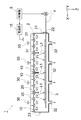
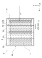
- FIG. 1 is a cross-sectional view schematically showing the configuration of an ultraviolet irradiation device according to the present invention.
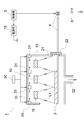
- FIG. 2 is a partially enlarged view of FIG.
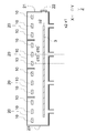
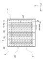
- FIG. 3 is a top view schematically showing the configuration of the ultraviolet irradiation device according to the present invention.
- FIG. 2 and FIG. 3 for convenience of explanation, the illustration of some of the elements shown in FIG. 1 is omitted.
- the ultraviolet irradiation device 1 includes a lamp house 2, a transport mechanism 4, and a control unit 5.
- the transport mechanism 4 is a mechanism for carrying the work 3 into the lamp house 2 and carrying out the work 3 from the lamp house 2, and is composed of known means such as a roller and a belt conveyor.
- the lamp house 2 includes a plurality of lamps 10 arranged at substantially equal intervals along the transport direction (X direction on the drawing). More specifically, similarly to the ultraviolet irradiation device 90 described above with reference to FIG. 8, the lamp house 2 includes a plurality of lamp units 20 arranged in the X direction, and in each lamp unit 20, in the X direction. A plurality of lamps 10 arranged apart from each other are mounted. However, all the lamps 10 mounted on the lamp house 2 may be configured as one lamp unit 20.
- Each lamp 10 has a shape extending in a direction different from the X direction (here, the Y direction). The shape of the lamp 10 will be described later. Further, in the following description, it is assumed that the + Z direction is vertically downward, but in the present invention, the direction in which the ultraviolet irradiation device 1 is installed does not matter.
- ultraviolet rays L1 are irradiated from a plurality of lamps 10 mounted on the lamp house 2 to perform surface treatment on the work 3.
- a separation distance from the lamp 10 is secured.
- the direction in which the work 3 and the lamp 10 are separated from each other may be referred to as the “Z direction”.
- the work 3 is held by a work holder (not shown), and the work 3 may be carried into the lamp house 2 by being conveyed together with the work holder by the transfer mechanism 4.
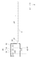
- FIG. 4 is a cross-sectional view schematically showing the structure of the lamp 10. In FIG. 4, two adjacent lamps 10 are shown for convenience of explanation.
- the lamp 10 has an arc tube 11 extending in the Y direction.
- the arc tube 11 has a rectangular shape when viewed in the Y direction.
- a pair of electrodes (12, 13) facing each other via the arc tube 11 are formed on the tube wall of the arc tube 11.
- the electrode formed on the tube wall on the side close to the work 3 (that is, the + Z side) is referred to as the “first electrode 12”, and is formed on the tube wall on the opposite side (that is, the ⁇ Z side).
- the electrode is referred to as a "second electrode 13".
- a luminescent gas 14G that forms excimer molecules by electric discharge is sealed in the arc tube 11.
- the luminescent gas 14G can be, for example, a gas containing xenon (Xe).
- a high-frequency AC voltage of, for example, about 50 kHz to 5 MHz is applied between both electrodes (12, 13) from the power supply unit 15 (see FIG. 1) via a feeder line, the arc tube 11 is connected to the light emitting gas 14G. The voltage is applied through.
- a discharge plasma is generated in the discharge space in which the luminescent gas 14G is enclosed, an atom of the luminescent gas 14G is excited to enter an excimer state, and when this atom shifts to the ground state, excimer emission is generated.
- the above-mentioned gas containing xenon (Xe) is used as the luminescent gas 14G, this excimer emission becomes ultraviolet L1 having a peak wavelength in the vicinity of 172 nm.
- the wavelength of the ultraviolet L1 can be changed by changing the substance used as the luminescent gas 14G.
- the luminescent gas 14G materials that emit vacuum ultraviolet light such as ArBr (peak wavelength near 165 nm), ArCl (peak wavelength near 175 nm), ArF (peak wavelength near 193 nm), and F 2 (peak wavelength near 153 nm) are used. can.
- At least the first electrode 12 has a mesh shape or a linear shape so that the ultraviolet L1 generated in the arc tube 11 does not hinder the progress in the + Z direction toward the work 3.
- the second electrode 13 may have a mesh shape, a linear shape, or a film shape. In the case of a film shape, the reflective film may be formed on the inner wall of the arc tube 11.
- the power supply unit 15 sets the first electrode 12 formed on the tube wall on the work 3 side to the low voltage side (more specifically, the ground side), and is opposite to the work 3.
- a rectangular voltage is applied between both electrodes (12, 13) so that the second electrode 13 formed on the tube wall on the side is on the high voltage side.
- a ground voltage may be applied to the second electrode 13 of the other adjacent lamp 10.
- the separation distance d10 between the lamps (10, 10) in the X direction is a certain distance or more. This separation distance d10 corresponds to the lamp pitch. In the following, the separation distance d10 between the central portions of the lamps (10, 10) in the X direction may be simply abbreviated as "separation distance d10".
- the separation distance d10 is preferably 1.9 times or more the width X10 related to the X direction of the lamp 10.
- the separation distance d10 is preferably 3 times or less the width X10 related to the X direction of the lamp 10.
- the lamp spacing d11 between adjacent lamps 10 is preferably 0.9 times or more and 2 times or less the width X10 of the lamps 10 in the X direction.
- the control unit 5 is a mechanism for controlling the transport mechanism 4 and the power supply unit 15, and is composed of dedicated hardware or software. The content of control performed by the control unit 5 will be described later.
- the lamp house 2 is provided with an entrance / exit opening end 21 at one end in the X direction.
- the lamp house 2 includes a shutter 22 capable of closing the entrance / exit opening end 21. By moving the position of the shutter 22, the entrance / exit opening end 21 is opened, and a state in which the work 3 can be carried into the lamp house 2 is realized.
- the lamp house 2 has a closed end 23 at the other end in the X direction. That is, the end of the lamp house 2 opposite to the entrance / exit opening end 21 is closed. Therefore, the work 3 is not transported to the position on the + X side of the closed end 23, in other words, the work 3 is not carried out to the outside of the lamp house 2 in the direction of the + X side.
- the lamp house 2 includes an inert gas introduction mechanism 31 arranged corresponding to the lamp unit 20.
- the inert gas introduction mechanism 31 supplies the inert gas delivered from the inert gas source 30 into the lamp unit 20.
- the lamp house 2 includes an exhaust mechanism 32 arranged corresponding to the lamp unit 20. Although the exhaust mechanism 32 is shown in the open state in FIGS. 1 and 2, the exhaust mechanism 32 may be capable of controlling the opening and closing of the exhaust port.
- each lamp is introduced into each lamp unit 20 from the inert gas introduction mechanism 31 arranged corresponding to the lamp unit 20 until the oxygen concentration contained in the atmospheric gas becomes equal to or less than a predetermined value.
- the inert gas introduction mechanisms 31 are arranged above the lamp 10 (-Z side) so as to face each other, and the inert gas introduction mechanisms 31 are supplied from the respective inert gas introduction mechanisms 31.
- the active gas is preferably supplied so as to collide above the lamp 10. As a result, the inert gas is slowly poured into the region irradiated with the ultraviolet L1, so that the oxygen concentration contained in the atmospheric gas in the irradiated region is less likely to vary.
- FIGS. 5A to 5C are drawings schematically showing the position of the work 3 at a certain time point during processing.
- FIGS. 5A to 5C are cross-sectional views
- FIGS. 6A to 6C are top views. handle. However, for convenience of illustration, some elements are omitted in FIGS. 5A to 5C and 6A to 6C.
- Step S1 As shown in FIGS. 5A and 6A, the control unit 5 controls the transport mechanism 4 to transport the work 3 in the + X direction, thereby carrying the work 3 into the lamp house 2 (arrow p1). At this time, the shutter 22 is open, and the entrance / exit opening end 21 is in an open state. In step S1, the entire work 3 is conveyed until it is located inside the lamp house 2 (see also FIG. 3).
- This step S1 corresponds to the step (a).
- the case where the X coordinate of the end position on the ⁇ X side of the work 3 is x1 is shown at the time of completion of the step S1.
- Step S2 The control unit 5 controls the power supply unit 15 to apply a voltage to each lamp 10 to light the lamp 10. As a result, the ultraviolet L1 from the lamp 10 is applied to the work 3. It may be assumed that the shutter 22 is closed by the control unit 5 and the entrance / exit opening end 21 is closed from step S2 until the step S4, which will be described later, is completed.
- This step S2 corresponds to the process (b1).
- Step S3 The control unit 5 controls the power supply unit 15 to turn off each lamp 10 and, as shown in FIGS. 5B and 6B, controls the transport mechanism 4 to transport the work 3 in the + X direction (arrow p2). ..
- the work 3 is moved in the + X direction by a distance of 1/2 of the separation distance d10 between the adjacent lamps (10, 10).
- the X coordinate of the end position on the ⁇ X side of the work 3 changes from x1 to x2 (see also FIG. 3).
- This step S3 corresponds to the step (b2).
- Step S4 The control unit 5 controls the power supply unit 15 to apply a voltage to each lamp 10 to light the lamp 10. As a result, the work 3 is irradiated with the ultraviolet L1 from the lamp 10 at a position different from that in step S2.
- This step S4 corresponds to the step (b3).
- Step S5 The control unit 5 controls the power supply unit 15 to turn off each lamp 10 and, as shown in FIGS. 5C and 6C, controls the transport mechanism 4 to transport the work 3 in the ⁇ X direction, and the lamp house. Carry it out of 2 (arrow p3).
- the same reference numerals are given to FIG.
- This step S5 corresponds to the step (c).
- the region of the work 3 facing the intermediate position between the adjacent lamps 10 arranged in the X direction has the lowest illuminance.
- the region of the work 3 facing the central position in the X direction of the lamps 10 arranged in the X direction has the highest illuminance.
- the ultraviolet L1 is irradiated in step S4. Therefore, the region of the work 3 having the lowest illuminance in step S2 is irradiated with the ultraviolet L1 from the lamp 10 at the position where the illuminance is highest in step S4. On the contrary, the region of the work 3 having the highest illuminance in step S2 is irradiated with the ultraviolet L1 from the lamp 10 at the position where the illuminance is the lowest in step S4. As a result, the uniformity of the illuminance on the surface of the work 3 is enhanced.
- the tip of the work 3 is closed on the side opposite to the entrance / exit opening end 21 from the time when the work 3 is carried into the lamp house 2 until the work 3 is carried out to the outside of the lamp house 2. Not exposed to the outside from the end 23. Therefore, it is not necessary to provide the evacuation area 73 of the work 3 as in the method described with reference to FIG. As a result, the footprint of the ultraviolet irradiation device 1 is reduced.
- the transport distance of the work 3 during processing is shorter. As a result, the takt time is shortened.
- Steps S2 to S4 are processes intended to irradiate ultraviolet L1 with the relative positions of the work 3 with respect to the plurality of lamps 10 being different. Therefore, steps S3 and S4 may be repeatedly executed a plurality of times.
- the ultraviolet rays L1 from the plurality of lamps 10 are irradiated to the work 3 in step S2
- the ultraviolet rays L1 from the plurality of lamps 10 are irradiated to the work 3 at different positions in step S4. It was an aspect to be done. That is, the number of irradiations was two. On the other hand, the number of irradiations may be 3 or more by repeatedly executing steps S3 and S4.
- the irradiation time in each step S4 is set shorter according to the number of irradiations. That is, the total irradiation time of the ultraviolet rays L1 irradiated to the work 3 from the start time of the treatment to the end of the treatment is set to a preset value as the time required for the treatment on the work 3, and the steps S3 and the step. It does not change depending on the number of repetitions of S4.
- the uneven illuminance on the surface of the work 3 is further alleviated.
- the processing time is about several seconds longer than in the case where the step S3 and the step S4 are executed once. Therefore, the number of executions of steps S3 and S4 may be appropriately set according to the uniformity of illuminance required for the work 3 and the short processing time.
- the position of the work 3 is determined by executing steps S3 and S4 once or a plurality of times after the work 3 is irradiated with ultraviolet rays L1 at the initial position in step S2. It was a mode in which ultraviolet rays L1 were irradiated in a different state.
- the number of steps S3 and S4 is increased infinitely, it corresponds to continuously performing steps S2 to S4.
- step S2 after starting the irradiation of the work 3 with ultraviolet rays L1 at the initial position, the following step S3a may be executed.
- Step S3a The control unit 5 controls the transport mechanism 4 to transport the work 3 in the + X direction while the lamps 10 are continuously lit. At this time, the transport distance of the work 3 is set so as to be within the separation distance d10 between the adjacent lamps (10, 10). The transport distance of the work 3 is preferably within the separation distance d10 and as close to d10 as possible.
- This step S3a corresponds to the step (b2).
- step S5 is executed, and the work 3 is carried out from the entrance / exit opening end 21 to the outside of the lamp house 2.
- This method also eliminates the uneven illuminance on the surface of the work 3 and reduces the tact time.
- the transport speed at the time of carrying in in step S1 and at the time of carrying out in step S5 may be set to be faster than the transport speed in step S3a. As a result, the tact time can be shortened as compared with the conventional method while ensuring the irradiation time required for the processing of the work 3.
- the plurality of lamps 10 included in the ultraviolet irradiation device (1,90) all had an effective emission length of 2200 mm and a surface illuminance of 170 mW / cm 2 or more, and the shape shown in FIG. 4 was adopted.
- the ultraviolet irradiation device (1,90) had a configuration in which four sets of lamp units 20 in which three lamps 10 were arranged in the X direction were arranged in the X direction.
- the separation distance d10 of the pair of lamps (10, 10) adjacent to each other in the X direction was 160 mm.
- Example 2 The work 3 was irradiated with ultraviolet L1 in the same manner as in Example 1 except that steps S3 and S4 were repeatedly executed twice. That is, in Example 2, the work 3 was irradiated with ultraviolet rays L1 three times (steps S2 and S4). The moving distance of the work 3 in each step S3 was set to 160 mm / 3 ⁇ 53 mm.
- Example 4 As compared to Example 1, step S3a was performed instead of step S3 and step S4. That is, in Example 4, the work 3 was continuously irradiated with ultraviolet rays L1. The moving distance of the work 3 in step S3a was set to 160 mm.
- the results of this experiment are shown in Table 1.
- the tact time is such that the required dose of ultraviolet L1 is irradiated from the time when the work 3 is started to be carried into the lamp house (20, 70) and the work 3 is irradiated from the lamp house (20, 70). Corresponds to the time until the time when 3 is carried out.
- the unit of "uniformity” is " ⁇ %" because the illuminance shifts from the intermediate value to the higher side (+ side) and the lower side (-side) in the region where the illuminance repeats the amplitude. ) Is intended to indicate that the illuminance that shifts to) is within the range of the values specified by the uniformity.
- Evaluation A is evaluated as having a uniformity of 20% or less and a takt time of 65 seconds or less, satisfying the demands of the market. Further, “evaluation B” is evaluated as not satisfying either the condition of the uniformity of 20% or less and the tact time of 65 seconds or less, and cannot satisfy the market demand.
- Comparative Example 2 the uniformity of the illuminance of the ultraviolet L1 on the surface of the work 3 is extremely low as compared with Examples 1 to 4. This is because the illuminance of the ultraviolet L1 varies between the region of the work 3 facing the intermediate position of the lamps (10, 10) adjacent to the X direction and the region of the work 3 facing the vicinity of the center of the lamp 10. it is conceivable that.
- Examples 1 to 4 it is confirmed that the takt time can be significantly shortened as compared with Comparative Example 1 and the uniformity of illuminance on the surface of the work 3 can be improved as compared with Comparative Example 2. Comparing Examples 1 to 4, it was confirmed that according to the method of Example 4, the uniformity of illuminance was maximized while the tact time was the shortest.
- the number of lamps 10 included in the ultraviolet irradiation device 1 is not limited. Further, the lamp 10 is not limited to the shape described above with reference to FIG.
- the ultraviolet irradiation device 1 includes the inert gas introduction mechanism 31 and the exhaust mechanism 32 has been described.
- the ultraviolet irradiation device 1 that does not have the inert gas introduction mechanism 31 and the exhaust mechanism 32 is also within the scope of the present invention.
- the present invention can be applied even when the voltage waveforms applied to the plurality of lamps 10 can be completely synchronized.
- the lamp house 2 included in the ultraviolet irradiation device 1 includes a plurality of lamps 10 arranged at substantially equal intervals along the transport direction (X direction) has been described.
- the lamp 10 is arranged to perform surface treatment on the work 3 by irradiating the work 3 with ultraviolet rays L1.
- the ultraviolet irradiation device 1 does not exclude a configuration in which the lamp house 2 is provided with another lamp (environmental adjustment lamp 40) in addition to the lamp 10.
- the environment-adjusting lamp 40 is provided for the purpose of raising the temperature inside the lamp house 2, for example.
- the environment adjustment lamp 40 may be an excimer lamp or another lamp such as an incandescent lamp.
- the environment adjustment lamps 40 do not need to be arranged at equal intervals like the lamps 10.
- the environment adjustment lamp 40 may be arranged on the entrance / exit opening end 21 side or the closing end 23 side in the lamp house 2.
- the environment adjusting lamp 40 may be arranged in the lamp house 2 at a position different from that of the lamp 10 in the Y direction.
- the environment adjustment lamps 40 may be arranged at equal intervals with the lamps 10 in the X direction.
- the lamp located on the outermost side of the plurality of lamps 10 groups arranged in the X direction may function as the environment adjustment lamp 40.
- Ultraviolet irradiation device 2 Lamp house 3: Work 4: Conveyance mechanism 5: Control unit 10: Lamp 11: Light emitting tube 12: First electrode 13: Second electrode 14G: Luminous gas 15: Power supply unit 20: Lamp unit 21 : Doorway opening end 22: Shutter 23: Closed end 30: Inert gas source 31: Inert gas introduction mechanism 32: Exhaust mechanism 40: Environmental adjustment lamp 70: Lamp house 71: End 72: End 73: Evacuation area 90: Ultraviolet irradiation device L1: Ultraviolet d10: Separation distance (lamp pitch) between central portions related to the transport direction of the lamp
Landscapes
- Cleaning Or Drying Semiconductors (AREA)
- Application Of Or Painting With Fluid Materials (AREA)
- Physical Or Chemical Processes And Apparatus (AREA)
- Cleaning In General (AREA)
Abstract
フットプリントの縮小化とワーク処理に要するタクトタイムの短縮化を両立した、紫外線照射装置を提供する。 紫外線照射装置は、紫外線を発する複数のランプが実質的に等間隔に並べられてなるランプハウスと、ワークを搬送する搬送機構と、制御部とを備える。ランプハウスは、ワークを内側に搬入するための出入口開口端と、反対側の閉塞端とを有する。制御部は、ワークの全体がランプハウスの内側に位置するまで正方向に搬送する工程(a)、ワークの先端が閉塞端よりも外側に出ない範囲内でワークを正方向に搬送し、複数のランプとの相対的な位置を異ならせた状態で紫外線をワークに照射する工程(b)、及びワークを負方向に搬送してランプハウスの外側に出す工程(c)を実行する制御を行う。工程(b)によってワークが正方向に移動される距離の合計は、隣接する1対のランプの搬送方向に係る中心部同士の離間距離以内である。
Description
本発明は、紫外線照射装置に関し、より詳細には、搬送されるワークに対して紫外線を照射することでワークの処理を行う装置に関する。
従来、ワークに対して紫外線を照射してワークの表面を処理する技術が知られている。例えば、下記特許文献1には、液晶表示パネル用のガラス基板、半導体ウエハ、半導体製造用のマスク基板などの基板の表面に紫外線を照射することで、その表面に付着した有機物を分解して除去したり、表面を親水化する技術が開示されている。
従来、ランプが複数搭載されたチャンバ内にワークを固定的に載置し、ランプからの紫外線を照射してワークの表面を処理した後、チャンバから取り出す技術が存在していた。しかし、ワークの大型化に伴って、表面処理に必要なランプ本数が増加を余儀なくされた。また、技術革新により、ランプの高輝度化が進められてきた。
かかる場合、ランプの直下の位置と、隣接するランプの隙間の直下の位置とでは、照度に差が生じる。この結果、ワークの表面の位置における処理ムラが生じるおそれがある。
なお、ワークの大きさに伴ってランプを大型化できれば、上記の課題は生じないとも思われる。しかし、大型のガラスによって水平な光取り出し面を形成することが技術的に難しい上、排熱の問題も生じるため、現実的には、ワークの大きさに合わせて複数のランプを配列せざるを得ない。このため、ワークを停止させた状態で紫外線を照射する従来の方法では、ワークの大型化に伴って処理ムラが無視できない問題となってきた。
上記の事情から、ワークを移動させながら紫外線を照射する技術が考えられている。この技術につき、図8を参照しながら説明する。図8は、従来の紫外線照射装置の処理方法を説明するための、模式的な平面図である。
図8に示す紫外線照射装置90は、搬送方向(X方向)に沿って配置された複数のランプ10を含むランプハウス70を備える。より詳細には、ランプハウス70は、X方向に沿って配置された複数のランプ10を搭載するランプユニット20を複数備える。ワーク3は、複数のランプ10が点灯中に、ランプハウス70の端部71から+X方向の向きにランプハウス70内に搬送され、端部71とは反対側の端部72からランプハウス70の外に搬出される。その後、ワーク3は、搬送方向が反転されて-X方向の向きに搬送されることで、ランプ10が点灯中のランプハウス70内に搬入され、再び端部71から搬出される。
上記のように、ワーク3を搬送しながら複数のランプ10からの紫外線をワーク3に対して照射することで、ワーク3の表面全体に対して実質的に同一の照度の紫外線を照射することができる。これにより、ワーク3の表面の処理ムラが抑制される。
しかし、上記の方法によれば、ランプハウス70の端部72側に、ワーク3の退避エリア73を設ける必要があり、紫外線照射装置90を設置するために確保しなければならないフットプリントが増大してしまう。
また、ワーク3に対して処理を完了させる迄に、ワーク3をランプハウス70のX方向に係る幅の2倍以上の距離だけ搬送させる必要がある。この結果、タクトタイムが長くなってしまう。タクトタイムを短くするためには、搬送速度を速める方法が考えられるが、あまりに速い速度でワーク3を搬送させると、ワーク3を処理するために必要な積算光量が確保できない。つまり、紫外線の照射中にワーク3の搬送速度を速めることには限界がある。
本発明は、上記の課題に鑑み、フットプリントの縮小化とワーク処理に要するタクトタイムの短縮化を両立した、紫外線照射装置を提供することを目的とする。
本発明は、搬送されるワークに対して紫外線を照射する紫外線照射装置であって、
前記ワークを搬送方向に搬送する搬送機構と、
前記紫外線を発する複数のランプが前記搬送方向に沿って実質的に等間隔に並べられてなるランプハウスと、
前記搬送機構の動作及び前記複数のランプの発光を制御する制御部とを備え、
前記ランプハウスは、前記紫外線の照射方向に見て前記ワークを内側に搬入するための出入口開口端と、前記搬送方向に関して前記出入口開口端とは反対側の閉塞端とを有し、
前記制御部は、
前記紫外線の照射方向に見て、前記ワークの全体が前記ランプハウスの内側に位置するまで、前記ワークを、前記出入口開口端から正の前記搬送方向に搬送する工程(a)と、
前記工程(a)の後、前記ワークの先端が前記閉塞端よりも外側に出ない範囲内で前記ワークを正の前記搬送方向に沿って搬送し、前記複数のランプと前記ワークとの相対的な位置を異ならせた状態で、前記複数のランプから前記紫外線を前記ワークに照射する工程(b)と、
前記工程(b)の実行後、前記ワークを前記工程(a)及び前記工程(b)とは逆向きである負の前記搬送方向に沿って搬送して、前記紫外線の照射方向に見て前記出入口開口端から前記ランプハウスの外側に前記ワークを出す工程(c)とを実行する制御を行い、
前記工程(b)によって前記ワークが正の前記搬送方向に移動される距離の合計が、前記搬送方向に隣接する1対の前記ランプの前記搬送方向に係る中心部同士の離間距離以内であることを特徴とする。
前記ワークを搬送方向に搬送する搬送機構と、
前記紫外線を発する複数のランプが前記搬送方向に沿って実質的に等間隔に並べられてなるランプハウスと、
前記搬送機構の動作及び前記複数のランプの発光を制御する制御部とを備え、
前記ランプハウスは、前記紫外線の照射方向に見て前記ワークを内側に搬入するための出入口開口端と、前記搬送方向に関して前記出入口開口端とは反対側の閉塞端とを有し、
前記制御部は、
前記紫外線の照射方向に見て、前記ワークの全体が前記ランプハウスの内側に位置するまで、前記ワークを、前記出入口開口端から正の前記搬送方向に搬送する工程(a)と、
前記工程(a)の後、前記ワークの先端が前記閉塞端よりも外側に出ない範囲内で前記ワークを正の前記搬送方向に沿って搬送し、前記複数のランプと前記ワークとの相対的な位置を異ならせた状態で、前記複数のランプから前記紫外線を前記ワークに照射する工程(b)と、
前記工程(b)の実行後、前記ワークを前記工程(a)及び前記工程(b)とは逆向きである負の前記搬送方向に沿って搬送して、前記紫外線の照射方向に見て前記出入口開口端から前記ランプハウスの外側に前記ワークを出す工程(c)とを実行する制御を行い、
前記工程(b)によって前記ワークが正の前記搬送方向に移動される距離の合計が、前記搬送方向に隣接する1対の前記ランプの前記搬送方向に係る中心部同士の離間距離以内であることを特徴とする。
本明細書において、複数のランプが搬送方向に沿って「実質的に等間隔」に並べられているとは、隣接する各ランプ間の前記搬送方向に係る中心部同士の離間距離(ランプピッチ)が、完全に一致している場合はもちろんのこと、ランプピッチが製造時の誤差範囲内において異なっている場合を含む趣旨である。後者は、ランプピッチの平均値に対する、全てのランプピッチの最大値と最小値の差の割合が、5%以内である場合を指す。
上記構成によれば、ワークが完全にランプハウスの内側に位置するまで正の方向に搬送された時点から、ワークをランプハウスの外側に搬出すべく負の方向に搬送を開始する迄の間に、ワークの位置を異ならせた状態でランプから紫外線が照射される。これにより、照度ムラの発生が抑制される。
また、ワークが完全にランプハウスの内側に位置するまで正の方向に搬送された時点から、ワークが負の方向に搬送を開始する迄の間に、ワークが正の方向に搬送される距離の合計は、隣接する1対のランプの搬送方向に係る中心部同士の離間距離、すなわちランプピッチ以内である。このため、ワークを移動させるのに要する時間を従来よりも短くできるため、タクトタイムが短縮化される。
更に、上記構成によれば、ワークを、ランプハウスの出入口開口端とは反対側の端部から外側に退避させる必要がない。この結果、紫外線照射装置のフットプリントを縮小できる。なお、かかる観点から、ランプハウスの出入口開口端とは反対側の端部は、閉塞端とすることができる。
前記工程(b)は、
前記工程(a)の実行後の前記ワークの位置において、前記紫外線を前記ワークに照射する工程(b1)と、
前記工程(b1)の実行後、前記複数のランプを消灯した状態で前記ワークを正の前記搬送方向に沿って搬送する工程(b2)と、
前記工程(b2)の実行後の前記ワークの位置において、前記紫外線を前記ワークに照射する工程(b3)とを有し、
前記工程(c)は、前記工程(b2)及び前記工程(b3)が1回ずつ又は複数回繰り返し実行された後、前記複数のランプを消灯した状態で実行される工程であるものとしても構わない。
前記工程(a)の実行後の前記ワークの位置において、前記紫外線を前記ワークに照射する工程(b1)と、
前記工程(b1)の実行後、前記複数のランプを消灯した状態で前記ワークを正の前記搬送方向に沿って搬送する工程(b2)と、
前記工程(b2)の実行後の前記ワークの位置において、前記紫外線を前記ワークに照射する工程(b3)とを有し、
前記工程(c)は、前記工程(b2)及び前記工程(b3)が1回ずつ又は複数回繰り返し実行された後、前記複数のランプを消灯した状態で実行される工程であるものとしても構わない。
上記構成によれば、ワークは複数のランプに対する相対的な位置を異ならせた状態で、複数回にわたって分割的に照射される。これにより、照度ムラの発生が抑制される。
前記工程(c)は、前記工程(b2)及び前記工程(b3)が1回ずつ実行された後に、実行され、
前記工程(b2)は、前記搬送方向に隣接する1対の前記ランプの前記搬送方向に係る中心部同士の離間距離に対して、実質的に1/2の距離だけ搬送する工程であるものとしても構わない。
前記工程(b2)は、前記搬送方向に隣接する1対の前記ランプの前記搬送方向に係る中心部同士の離間距離に対して、実質的に1/2の距離だけ搬送する工程であるものとしても構わない。
なお、ここでいう「ランプの搬送方向に係る中心部同士の離間距離に対して実質的に1/2の距離」とは、厳密な意味においてランプの搬送方向に係る中心部同士の離間距離(すなわちランプピッチ)の1/2の距離である場合はもちろん、動作制御上の誤差範囲内において異なっている場合を含む趣旨である。ここでいう動作制御上の誤差範囲とは、ランプの搬送方向に係る中心部同士の離間距離に対して±5%以内を指す。
前記工程(c)は、前記工程(b2)及び前記工程(b3)の一連の処理が、それぞれn回(nは自然数)繰り返し実行された後に、実行され、
前記工程(b2)は、各回において、前記搬送方向に隣接する1対の前記ランプの前記搬送方向に係る中心部同士の離間距離に対して、実質的に1/(n+1)の距離だけ搬送する工程であるものとしても構わない。
前記工程(b2)は、各回において、前記搬送方向に隣接する1対の前記ランプの前記搬送方向に係る中心部同士の離間距離に対して、実質的に1/(n+1)の距離だけ搬送する工程であるものとしても構わない。
なお、ここでいう「ランプの搬送方向に係る中心部同士の離間距離に対して実質的に1/(n+1)の距離」とは、厳密な意味においてランプの搬送方向に係る中心部同士の離間距離の1/(n+1)の距離である場合はもちろん、動作制御上の誤差範囲内において異なっている場合を含む趣旨である。ここでいう動作制御上の誤差範囲とは、ランプの搬送方向に係る中心部同士の離間距離に対して±(5/n)%以内を指す。
前記工程(b)は、
前記工程(a)の実行後の前記ワークの位置において、前記複数のランプから前記紫外線を前記ワークに照射を開始する工程(b1)と、
前記複数のランプから前記紫外線を照射しながら、前記ワークを正の前記搬送方向に沿って、前記搬送方向に隣接する1対の前記ランプの前記搬送方向に係る中心部同士の離間距離以内だけ搬送する工程(b2)とを有し、
前記工程(c)は、前記工程(b2)の実行後に、前記複数のランプを消灯した状態で実行されるものとしても構わない。
前記工程(a)の実行後の前記ワークの位置において、前記複数のランプから前記紫外線を前記ワークに照射を開始する工程(b1)と、
前記複数のランプから前記紫外線を照射しながら、前記ワークを正の前記搬送方向に沿って、前記搬送方向に隣接する1対の前記ランプの前記搬送方向に係る中心部同士の離間距離以内だけ搬送する工程(b2)とを有し、
前記工程(c)は、前記工程(b2)の実行後に、前記複数のランプを消灯した状態で実行されるものとしても構わない。
上記構成によれば、ワークは複数のランプに対する相対的な位置を異ならせながら連続的に照射される。これにより、照度ムラの発生が抑制される。なお、この場合においても、照射中におけるワークの搬送距離は、ランプの隣接する1対のランプの離間距離以内であるため、タクトタイムは従来より短縮化される。
前記工程(a)及び前記工程(c)は、前記工程(b2)よりも速い速度で前記ワークが搬送される工程であるものとしても構わない。
これにより、処理に必要な照射線量を確保しつつ、タクトタイムの更なる短縮化を図ることができる。
前記ランプハウスは、
所定数の前記ランプを収容するランプユニットが前記搬送方向に沿って複数配置されてなり、
前記ランプユニットに対応して配置され、前記ワークに対して不活性ガスを供給する複数の不活性ガス導入機構と、
前記ランプユニットに対応して配置され、前記ランプハウス内に存在する雰囲気ガスを前記ランプハウス外に排出する複数の排気機構とを備えるものとしても構わない。
所定数の前記ランプを収容するランプユニットが前記搬送方向に沿って複数配置されてなり、
前記ランプユニットに対応して配置され、前記ワークに対して不活性ガスを供給する複数の不活性ガス導入機構と、
前記ランプユニットに対応して配置され、前記ランプハウス内に存在する雰囲気ガスを前記ランプハウス外に排出する複数の排気機構とを備えるものとしても構わない。
例えば、複数のランプが、主たる発光波長が200nm未満の紫外線を発する場合、ランプとワークとの間の雰囲気の酸素濃度にムラが生じると、ワークに対する処理ムラの原因となる可能性がある。上記構成によれば、不活性ガス導入機構から不活性ガスを導入することができるため、酸素濃度を低くしつつ均一化が図られる。
ところで、上記紫外線照射装置の場合、出入口開口端とは反対側の端部が閉塞端とされているため、不活性ガス導入機構が1箇所しか設けられていない場合には、不活性ガスを各ランプとワークとの離間領域に均一に行き渡らせられないおそれがある。また、均一な酸素濃度を実現するためには、不活性ガスの導入に要する時間が長時間化するおそれもある。この点は、排気機構が1箇所しか設けられていない場合においても同様である。
上記の構成によれば、各ユニット単位で不活性ガス導入機構と排気機構とが備えられているため、短い時間で、各ランプとワークと離間領域の酸素濃度を均一化することができ、処理ムラの発現が抑制される。
ランプとしては、例えばXeを含む発光ガスが封入されたエキシマランプとすることができる。この場合、ランプの主たる発光波長は172nmとなる。発光ガスの材料を替えることで、主たる発光波長を異ならせることができる。例えば、Krガスの場合には146nmであり、ArBrガスの場合には165nmであり、ArFガスの場合には193nmである。
本明細書において「主たる発光波長」とは、ある波長λに対して±10nmの波長域Z(λ)を発光スペクトル上で規定した場合において、発光スペクトル内における全積分強度に対して40%以上の積分強度を示す波長域Z(λi)における、波長λiを指す。例えばXeなどの発光ガスが封入されているエキシマランプのように、半値幅が極めて狭く、且つ、特定の波長においてのみ光強度を示す光源においては、通常は、相対強度が最も高い波長(主ピーク波長)をもって、主たる発光波長として構わない。
前記複数のランプのそれぞれは、断面が矩形状を呈した発光管と、前記発光管の前記ワーク側の管壁に形成された第一電極と、前記発光管の前記ワークとは反対側の管壁に形成された第二電極とを有し、
前記制御部は、前記工程(c)において、前記第一電極に対して前記第二電極が正電圧となる矩形状の電圧を、前記複数のランプのそれぞれに対して個別に印加する制御を行うものとしても構わない。
前記制御部は、前記工程(c)において、前記第一電極に対して前記第二電極が正電圧となる矩形状の電圧を、前記複数のランプのそれぞれに対して個別に印加する制御を行うものとしても構わない。
各ランプに対して印加される電圧の波形に対して完全に同期を取るためには、同期形成用の回路と精査な制御が必要となる。一方で、同期が取れていない場合には、あるランプの第一電極に正電圧が印加されている最中に、隣接するランプの第一電極に接地電圧が印加されている場合が想定される。この場合、仮に、隣接するランプ間の距離(ランプピッチ)が極めて近接していると、絶縁破壊やコロナ放電を生じるおそれがある。このため、ランプピッチはある程度空けざるを得なくなる。
しかし、上記の構成によれば、ランプピッチがある程度の距離で存在していても、短いタクトタイムの下でワークに対する照度ムラを解消することが可能となる。
本発明の紫外線照射装置によれば、フットプリントの縮小化とワーク処理に要するタクトタイムの短縮化の両立が実現される。
本発明に係る紫外線照射装置の実施形態につき、適宜図面を参照して説明する。なお、以下の各図面は、模式的に図示されたものであり、図面上の寸法比と実際の寸法比は必ずしも一致していない。また、各図面間においても、寸法比は必ずしも一致していない。
以下の図において、図8を参照して上述した要素と同一の要素については、同一の符号を付して、その説明が適宜簡略化される。
〈構造〉
図1は、本発明に係る紫外線照射装置の構成を模式的に示す断面図である。図2は、図1の一部拡大図である。図3は、本発明に係る紫外線照射装置の構成を模式的に示す上面図である。なお、図2及び図3は、説明の都合上、図1に図示された一部の要素については図示が省略されている。
図1は、本発明に係る紫外線照射装置の構成を模式的に示す断面図である。図2は、図1の一部拡大図である。図3は、本発明に係る紫外線照射装置の構成を模式的に示す上面図である。なお、図2及び図3は、説明の都合上、図1に図示された一部の要素については図示が省略されている。
紫外線照射装置1は、ランプハウス2と、搬送機構4と、制御部5とを備える。搬送機構4は、ワーク3をランプハウス2内に搬入したり、ランプハウス2からワーク3を搬出するための機構であり、ローラやベルトコンベアなどの公知の手段で構成される。
ランプハウス2は、搬送方向(図面上X方向)に沿って実質的に等間隔に配置された複数のランプ10を含む。より詳細には、図8を参照して上述した紫外線照射装置90と同様に、ランプハウス2は、X方向に並べられた複数のランプユニット20を備え、各ランプユニット20内に、X方向に離間して配置された複数のランプ10が搭載されている。ただし、ランプハウス2に搭載されている全てのランプ10が、一つのランプユニット20として構成されていても構わない。
各ランプ10は、X方向とは異なる方向(ここではY方向とする。)に延伸する形状を呈している。ランプ10の形状については後述される。また、以下では、+Z方向が鉛直下向きであるものとして説明するが、本発明は、紫外線照射装置1が設置される向きは問わない。
搬送機構4によって、ワーク3がランプハウス2内に搬入された状態で、ランプハウス2に搭載された複数のランプ10から紫外線L1が照射されてワーク3に対して表面処理が施される。ワーク3は、ランプハウス2内に搬入された状態において、ランプ10との間で離間距離が確保されている。以下では、ワーク3とランプ10との離間方向を「Z方向」と呼ぶことがある。
なお、ワーク3は、図示しないワーク保持体によって保持されており、搬送機構4によってワーク保持体ごと搬送されることで、ワーク3がランプハウス2内に搬入されるものとしても構わない。
図4は、ランプ10の構造を模式的に示す断面図である。図4には、説明の都合上、隣接する2つのランプ10が図示されている。
ランプ10は、Y方向に延伸する発光管11を有する。発光管11は、Y方向に見たときに矩形状を呈している。そして、発光管11の管壁には、発光管11を介して対向する一対の電極(12,13)が形成されている。以下では、ワーク3に近い側(すなわち、+Z側)の管壁に形成されている電極を「第一電極12」と称し、その反対側に(すなわち、-Z側)の管壁に形成されている電極を「第二電極13」と称する。
発光管11内には、放電によってエキシマ分子を形成する発光ガス14Gが封入されている。発光ガス14Gは、例えばキセノン(Xe)を含むガスとすることができる。電源部15(図1参照)から給電線を介して両電極(12,13)の間に例えば50kHz~5MHz程度の高周波の交流電圧が印加されると、発光ガス14Gに対して発光管11を介して前記電圧が印加される。このとき、発光ガス14Gが封入されている放電空間内で放電プラズマが生じ、発光ガス14Gの原子が励起されてエキシマ状態となり、この原子が基底状態に移行する際にエキシマ発光を生じる。発光ガス14Gとして、上述したキセノン(Xe)を含むガスを用いた場合には、このエキシマ発光は、172nm近傍にピーク波長を有する紫外線L1となる。
なお、発光ガス14Gとして利用する物質を異ならせることで、紫外線L1の波長を変えることができる。例えば、発光ガス14Gとしては、ArBr(ピーク波長165nm近傍)、ArCl(ピーク波長175nm近傍)、ArF(ピーク波長193nm近傍)、F2(ピーク波長153nm近傍)など、真空紫外光を発する材料が利用できる。
なお、発光管11内で発生した紫外線L1が、ワーク3に向かって+Z方向に進行することへの妨げにならないよう、少なくとも第一電極12はメッシュ形状又は線形状を呈している。なお、発光管11の第二電極13側の壁面に反射膜を設けることで、発光管11内で発生し、第二電極13側に進行した紫外線L1を、ワーク3側に導くことができる。第二電極13は、メッシュ形状又は線形状であっても構わないし、膜形状であっても構わない。膜形状の場合には、反射膜は発光管11の内壁に形成されるものとして構わない。
ワーク3との間で放電が生じないよう、電源部15は、ワーク3側の管壁に形成された第一電極12を低電圧側(より詳細には接地側)とし、ワーク3とは反対側の管壁に形成された第二電極13を高電圧側とするように、両電極(12,13)間に矩形状の電圧を印加する。ただし、隣接するランプ10に印加される電圧波形に対して完全に同期を取ることができない場合があるため、隣接する一方のランプ10の第二電極13に高電圧が印加されている瞬間に、隣接する他方のランプ10の第二電極13に接地電圧が印加される場合が起こり得る。かかる場合、隣接する第二電極13同士に高い電位差が生じるため、ランプ(10,10)間の離間距離d10があまりに接近していると、ランプ(10,10)間で絶縁破壊やコロナ放電を生じるおそれがある。かかる観点から、ランプ(10,10)のX方向に係る中心部同士の離間距離d10は、一定距離以上離間させることが好ましい。この離間距離d10は、ランプピッチに対応する。なお、以下では、ランプ(10,10)のX方向に係る中心部同士の離間距離d10を、単に「離間距離d10」と略記することがある。
具体的には、離間距離d10は、ランプ10のX方向に係る幅X10の1.9倍以上とするのが好ましい。一方、離間距離d10をあまりに空けすぎるとワーク3に対する照度ムラが発生するため、離間距離d10は、ランプ10のX方向に係る幅X10の3倍以下とするのが好ましい。言い換えれば、隣接するランプ10同士のランプ間隔d11は、ランプ10のX方向に係る幅X10の0.9倍以上、2倍以下とするのが好ましい。
再び図1~図3に戻って説明を続ける。制御部5は、搬送機構4及び電源部15を制御する機構であり、専用のハードウェア又はソフトウェアで構成される。制御部5によって行われる制御内容については、後述される。
ランプハウス2は、X方向に係る一方の端部に出入口開口端21を備える。本実施形態では、ランプハウス2が出入口開口端21を閉塞可能なシャッター22を備える。シャッター22の位置を移動させることで、出入口開口端21が開放され、ワーク3をランプハウス2内に搬入可能な状態が実現される。
ランプハウス2は、X方向に係る他方の端部に閉塞端23を有する。すなわち、ランプハウス2は、出入口開口端21とは反対側の端部は閉塞されている。このため、ワーク3は閉塞端23よりも+X側の位置に搬送されることがなく、言い換えれば、ワーク3は+X側の方向に向かってランプハウス2の外側に搬出されることがない。
ランプハウス2は、ランプユニット20に対応して配置された、不活性ガス導入機構31を備えている。この不活性ガス導入機構31は、不活性ガス源30から送出された不活性ガスを、ランプユニット20内に供給する。また、ランプハウス2は、ランプユニット20に対応して配置された、排気機構32を備えている。図1及び図2では、排気機構32が開放状態である場合が図示されているが、排気機構32は、排気口の開閉制御が可能であるものとしても構わない。
上述したように、ランプ10が、波長200nm以下の真空紫外域の紫外線L1を発する構成である場合、ワーク3の表面処理を行う際には、ランプ10とワーク3との離間領域に存在する雰囲気内の酸素濃度を均一にすることが重要な要素となる。仮に、酸素濃度にムラが生じていると、雰囲気ガスに吸収される紫外線L1の量が場所によって変化してしまい、結果的に、ワーク3の表面に到達する紫外線L1の照度にムラが生じるおそれがあるためである。よって、雰囲気ガスに含まれる酸素濃度が所定値以下になるまで、ランプユニット20に対応して配置された不活性ガス導入機構31から各ランプユニット20内に不活性ガスを導入しながら、各ランプユニット20内の雰囲気ガスを排気機構32から排気することで、ランプハウス2内の雰囲気に含まれる酸素濃度を短時間で均一的に低下することができる。
なお、図2に示すように、ランプ10の上方(-Z側)の位置において、相互に向かい合うように不活性ガス導入機構31を配置し、それぞれの不活性ガス導入機構31から供給される不活性ガスを、ランプ10の上方で衝突させるように供給するのが好ましい。これにより、紫外線L1が照射される領域に対して緩やかに不活性ガスが流し込まれるため、照射領域内の雰囲気ガスに含まれる酸素濃度にばらつきが生じにくくなる。
[制御手順]
次に、本実施形態の紫外線照射装置1における、制御手順について説明する。図5A~図5C、図6A~図6Cは、処理中のある時点におけるワーク3の位置を模式的に示す図面であり、図5A~図5Cが断面図、図6A~図6Cが上面図に対応する。ただし、図示の都合上、図5A~図5C、及び図6A~図6Cにおいては、一部の要素が省略されている。
次に、本実施形態の紫外線照射装置1における、制御手順について説明する。図5A~図5C、図6A~図6Cは、処理中のある時点におけるワーク3の位置を模式的に示す図面であり、図5A~図5Cが断面図、図6A~図6Cが上面図に対応する。ただし、図示の都合上、図5A~図5C、及び図6A~図6Cにおいては、一部の要素が省略されている。
(ステップS1)
図5A及び図6Aに示すように、制御部5は、搬送機構4を制御してワーク3を+X方向に搬送することでランプハウス2内に搬入する(矢符p1)。このとき、シャッター22が空けられており、出入口開口端21は開放状態となっている。ステップS1では、ワーク3の全体がランプハウス2の内側に位置するまで搬送される(なお、図3も参照)。
図5A及び図6Aに示すように、制御部5は、搬送機構4を制御してワーク3を+X方向に搬送することでランプハウス2内に搬入する(矢符p1)。このとき、シャッター22が空けられており、出入口開口端21は開放状態となっている。ステップS1では、ワーク3の全体がランプハウス2の内側に位置するまで搬送される(なお、図3も参照)。
このステップS1が工程(a)に対応する。なお、図5A及び図6Aでは、本ステップS1の完了時点において、ワーク3の-X側の端部位置のX座標がx1である場合が図示されている。
(ステップS2)
制御部5は、電源部15を制御して、各ランプ10に対して電圧を印加してランプ10を点灯させる。これにより、ランプ10からの紫外線L1がワーク3に対して照射される。なお、ステップS2以後、後述するステップS4が完了する迄の間、制御部5によってシャッター22が閉められて、出入口開口端21が閉塞状態とされているものとして構わない。
制御部5は、電源部15を制御して、各ランプ10に対して電圧を印加してランプ10を点灯させる。これにより、ランプ10からの紫外線L1がワーク3に対して照射される。なお、ステップS2以後、後述するステップS4が完了する迄の間、制御部5によってシャッター22が閉められて、出入口開口端21が閉塞状態とされているものとして構わない。
このステップS2が工程(b1)に対応する。
(ステップS3)
制御部5は、電源部15を制御して各ランプ10を消灯させると共に、図5B及び図6Bに示すように、搬送機構4を制御してワーク3を+X方向に搬送させる(矢符p2)。ここでは、隣接するランプ(10,10)間の離間距離d10の1/2の距離だけ、ワーク3を+X方向に移動させる。この結果、本ステップS3の完了時点において、ワーク3の-X側の端部位置のX座標がx1からx2へと変化する(なお、図3も参照)。
制御部5は、電源部15を制御して各ランプ10を消灯させると共に、図5B及び図6Bに示すように、搬送機構4を制御してワーク3を+X方向に搬送させる(矢符p2)。ここでは、隣接するランプ(10,10)間の離間距離d10の1/2の距離だけ、ワーク3を+X方向に移動させる。この結果、本ステップS3の完了時点において、ワーク3の-X側の端部位置のX座標がx1からx2へと変化する(なお、図3も参照)。
このステップS3が工程(b2)に対応する。
(ステップS4)
制御部5は、電源部15を制御して、各ランプ10に対して電圧を印加してランプ10を点灯させる。これにより、ワーク3は、ステップS2とは異なる位置でランプ10からの紫外線L1が照射される。
制御部5は、電源部15を制御して、各ランプ10に対して電圧を印加してランプ10を点灯させる。これにより、ワーク3は、ステップS2とは異なる位置でランプ10からの紫外線L1が照射される。
このステップS4が工程(b3)に対応する。
(ステップS5)
制御部5は、電源部15を制御して各ランプ10を消灯させると共に、図5C及び図6Cに示すように、搬送機構4を制御してワーク3を-X方向に搬送させて、ランプハウス2の外側に搬出させる(矢符p3)。なお、図3にも同様の符号が付されている。
制御部5は、電源部15を制御して各ランプ10を消灯させると共に、図5C及び図6Cに示すように、搬送機構4を制御してワーク3を-X方向に搬送させて、ランプハウス2の外側に搬出させる(矢符p3)。なお、図3にも同様の符号が付されている。
このステップS5が工程(c)に対応する。
ステップS2においてワーク3に対して紫外線L1が照射される際、X方向に並んだ隣接するランプ10同士の中間位置に対向するワーク3の領域は、最も照度が低くなる。他方、X方向に並んだ各ランプ10の、X方向の中央の位置に対向するワーク3の領域は、最も照度が高くなる。
上記方法によれば、ステップS3において離間距離d10の1/2の距離だけ+X方向にワーク3が搬送された後、ステップS4において紫外線L1が照射される。このため、ステップS2で照度が最も低かったワーク3の領域は、ステップS4において照度が最も高くなる位置でランプ10からの紫外線L1が照射される。逆に、ステップS2で照度が最も高かったワーク3の領域は、ステップS4において照度が最も低くなる位置でランプ10からの紫外線L1が照射される。これにより、ワーク3の面上における照度の均一性が高められる。
また、上記方法によれば、ワーク3がランプハウス2内に搬入されてから、ランプハウス2の外側に搬出される迄の間、ワーク3の先端は、出入口開口端21とは反対側の閉塞端23から外側には露出しない。このため、図8を参照して説明した方法のように、ワーク3の退避エリア73を設ける必要がない。この結果、紫外線照射装置1のフットプリントが縮小される。
更に、図8を参照して説明した方法と比べて、処理中のワーク3の搬送距離は短くなる。これにより、タクトタイムが短縮化される。
[別の制御手順]
以下、別の手順について説明する。
以下、別の手順について説明する。
〈1〉ステップS2~S4は、複数のランプ10に対するワーク3の相対的な位置を異ならせた状態で紫外線L1を照射することを意図した処理である。このため、ステップS3及びS4は、複数回繰り返し実行されても構わない。
すなわち、上記実施形態では、ステップS2において複数のランプ10からの紫外線L1がワーク3に対して照射された後、ステップS4において異なる位置で複数のランプ10からの紫外線L1がワーク3に対して照射される態様であった。つまり、照射回数は2回であった。これに対し、ステップS3及びステップS4が繰り返し実行されることで、照射回数を3回以上としても構わない。
ただし、照射回数が増えた場合には、その回数に応じて、各ステップS4における照射時間が短く設定される。つまり、処理開始時点から、処理終了時点までにワーク3に対して照射される紫外線L1の合計照射時間は、ワーク3への処理に必要な時間として予め設定された値とされ、ステップS3及びステップS4の繰り返し回数によって変化するものではない。
この方法によれば、ステップS3及びステップS4が複数回実行されることで、ワーク3の表面に対する照度ムラが更に緩和される。ただし、ステップS3が複数回実行されることで、ワーク3が複数回にわたって搬送されることから、ステップS3及びステップS4が1回ずつ実行される場合と比べて、処理時間が数秒程度長くなる。このため、ワーク3に対して要求される照度の均一性と、処理時間の短さに応じて、ステップS3及びステップS4の実行回数が適宜設定されるものとして構わない。
〈2〉上記の方法は、ステップS2において初期の位置でワーク3に対して紫外線L1が照射された後、ステップS3及びステップS4が1回又は複数回実行されることで、ワーク3の位置を異ならせた状態で紫外線L1が照射される態様であった。ここで、ステップS3及びステップS4の回数を無限に増やすことを考えると、ステップS2からステップS4までを連続的に行うことに対応する。
つまり、ステップS2において、初期の位置においてワーク3に対して紫外線L1の照射を開始した後、下記のステップS3aを実行するものとしても構わない。
(ステップS3a)
制御部5は、引き続き各ランプ10を点灯させた状態のまま、搬送機構4を制御してワーク3を+X方向に搬送させる。このとき、ワーク3の搬送距離は、隣接するランプ(10,10)間の離間距離d10以内となるように設定される。なお、好ましくはワーク3の搬送距離は、前記離間距離d10以内であってできるだけd10に近い値である。
制御部5は、引き続き各ランプ10を点灯させた状態のまま、搬送機構4を制御してワーク3を+X方向に搬送させる。このとき、ワーク3の搬送距離は、隣接するランプ(10,10)間の離間距離d10以内となるように設定される。なお、好ましくはワーク3の搬送距離は、前記離間距離d10以内であってできるだけd10に近い値である。
このステップS3aが、工程(b2)に対応する。
そして、このステップS3aの完了後、上記ステップS5が実行されて、ワーク3が出入口開口端21からランプハウス2の外側に搬出される。この方法によっても、ワーク3の面上における照度ムラの解消と、タクトタイムの縮小化が図られる。なお、ステップS1における搬入時、及びステップS5における搬出時における搬送速度は、ステップS3aにおける搬送速度よりも速く設定されるものとしても構わない。これにより、ワーク3の処理に必要な照射時間を確保しつつ、従来方法よりもタクトタイムの短縮化が図られる。
[検証]
照射方法を異ならせて実験を行い、タクトタイム及び照度の均一性を測定した。
照射方法を異ならせて実験を行い、タクトタイム及び照度の均一性を測定した。
(共通条件)
紫外線照射装置(1,90)が備える複数のランプ10は、いずれも、有効発光長が2200mm、表面照度が170mW/cm2以上であり、図4に示す形状のものが採用された。紫外線照射装置(1,90)は、X方向に3本のランプ10が配置されたランプユニット20がX方向に4組並べられた構成であった。X方向に隣接する一対のランプ(10,10)の離間距離d10は、160mmであった。
紫外線照射装置(1,90)が備える複数のランプ10は、いずれも、有効発光長が2200mm、表面照度が170mW/cm2以上であり、図4に示す形状のものが採用された。紫外線照射装置(1,90)は、X方向に3本のランプ10が配置されたランプユニット20がX方向に4組並べられた構成であった。X方向に隣接する一対のランプ(10,10)の離間距離d10は、160mmであった。
ワーク3は、X方向×Y方向=1600mm×2100mmの大きさであり、樹脂からなる板材であった。ワーク3をランプハウス(20,70)内に搬入してから、ランプハウス(20,70)外へ搬出する迄の間に、複数のランプ10から発せられる紫外線L1によって、2000mJ/cm2の照射エネルギーをワーク3に対して与え、ワーク3の面上における照度の均一性と処理時間を比較した。
(比較例1)
図8を参照して上述した方法により、ランプハウス70内でワーク3を移動させながら、複数のランプ10からの紫外線L1を照射した。なお、この方法の場合、往路と復路の2回にわたってワーク3に対して紫外線が照射されるため、各ランプ10からの照射エネルギーは1000mJ/cm2に設定された。
図8を参照して上述した方法により、ランプハウス70内でワーク3を移動させながら、複数のランプ10からの紫外線L1を照射した。なお、この方法の場合、往路と復路の2回にわたってワーク3に対して紫外線が照射されるため、各ランプ10からの照射エネルギーは1000mJ/cm2に設定された。
(比較例2)
ステップS1においてワーク3をランプハウス2内に搬入した後、ワーク3の位置を移動させずに、複数のランプ10からの紫外線L1を2000mJ/cm2の照射エネルギーに達するまでワーク3に対して照射した。その後、ワーク3がランプハウス2の外側に搬出された。
ステップS1においてワーク3をランプハウス2内に搬入した後、ワーク3の位置を移動させずに、複数のランプ10からの紫外線L1を2000mJ/cm2の照射エネルギーに達するまでワーク3に対して照射した。その後、ワーク3がランプハウス2の外側に搬出された。
(実施例1)
本実施形態の紫外線照射装置1によって、上述したステップS1~S5の順に実行されることでワーク3に対する紫外線L1の照射処理が実行された。すなわち、実施例1では、ワーク3に対して紫外線L1が2回にわたって照射された(ステップS2,ステップS4)。なお、ステップS3におけるワーク3の移動距離は、160mm/2=80mmとされた。
本実施形態の紫外線照射装置1によって、上述したステップS1~S5の順に実行されることでワーク3に対する紫外線L1の照射処理が実行された。すなわち、実施例1では、ワーク3に対して紫外線L1が2回にわたって照射された(ステップS2,ステップS4)。なお、ステップS3におけるワーク3の移動距離は、160mm/2=80mmとされた。
(実施例2)
ステップS3及びステップS4が2回繰り返し実行された点以外は、実施例1と同様の方法で、ワーク3に対する紫外線L1の照射処理が実行された。すなわち、実施例2では、ワーク3に対して紫外線L1が3回にわたって照射された(ステップS2,ステップS4)。なお、各ステップS3におけるワーク3の移動距離は、160mm/3≒53mmとされた。
ステップS3及びステップS4が2回繰り返し実行された点以外は、実施例1と同様の方法で、ワーク3に対する紫外線L1の照射処理が実行された。すなわち、実施例2では、ワーク3に対して紫外線L1が3回にわたって照射された(ステップS2,ステップS4)。なお、各ステップS3におけるワーク3の移動距離は、160mm/3≒53mmとされた。
(実施例3)
ステップS3及びステップS4が3回繰り返し実行された点以外は、実施例1と同様の方法で、ワーク3に対する紫外線L1の照射処理が実行された。すなわち、実施例3では、ワーク3に対して紫外線L1が4回にわたって照射された(ステップS2,ステップS4)。なお、ステップS3におけるワーク3の移動距離は、160mm/4=40mmとされた。
ステップS3及びステップS4が3回繰り返し実行された点以外は、実施例1と同様の方法で、ワーク3に対する紫外線L1の照射処理が実行された。すなわち、実施例3では、ワーク3に対して紫外線L1が4回にわたって照射された(ステップS2,ステップS4)。なお、ステップS3におけるワーク3の移動距離は、160mm/4=40mmとされた。
(実施例4)
実施例1と比較して、ステップS3及びステップS4に替えて、ステップS3aが実行された。すなわち、実施例4では、ワーク3に対して紫外線L1が連続的に照射された。なお、ステップS3aにおけるワーク3の移動距離は、160mmとされた。
実施例1と比較して、ステップS3及びステップS4に替えて、ステップS3aが実行された。すなわち、実施例4では、ワーク3に対して紫外線L1が連続的に照射された。なお、ステップS3aにおけるワーク3の移動距離は、160mmとされた。
この実験結果を表1に示す。なお、タクトタイムは、ワーク3をランプハウス(20,70)内に向かってワーク3の搬入が開始される時点から、必要な線量の紫外線L1が照射されてランプハウス(20,70)からワーク3が搬出される時点までの時間に対応する。また、均一度は、各ランプ10が設置されている領域からZ方向に160mm離間した位置における照度(mJ/cm2)を照度計で測定し、照度分布内の最大値と最小値に基づいて、以下の式で算定された。
均一度[±%]=(最大値-最小値)/(最大値+最小値)×100
均一度[±%]=(最大値-最小値)/(最大値+最小値)×100
なお、上記において「均一度」の単位が「±%」とされているのは、照度が振幅を繰り返す領域において、中間値から高い側(+側)にシフトする照度と、低い側(-側)にシフトする照度が、それぞれ均一度で規定される値の範囲内にある、ということを表す意図である。

なお、表1において「評価A」は、均一度が20%以下であって、しかもタクトタイムが65秒以下であり、市場の要求を満足すると評価されるものである。また、「評価B」は、均一度が20%以下、タクトタイムが65秒以下のどちらかの条件を満足できず、市場の要求を満足できないと評価されるものである。
表1によれば、比較例1では、実施例1~4と比べて、タクトタイムが大幅に長いことが確認される。これは、図8を参照して上述したように、ランプハウス70内においてワーク3を往復させる必要があるため、ワーク3の搬送距離がランプハウス70のX方向に係る幅の約2倍の距離(3560mm)に達し、搬送に係る時間が長くなったことが理由として考えられる。なお、図8を参照して上述したように、比較例1では退避エリア73が必要になることから、フットプリントの観点からも比較例1よりは実施例1~4の方が好ましいといえる。
また、比較例2では実施例1~4と比べて、ワーク3の表面における紫外線L1の照度の均一性が極めて低くなっている。これは、X方向に隣接するランプ(10,10)の中間の位置に対向するワーク3の領域と、ランプ10の中央付近に対向するワーク3の領域とで紫外線L1の照度にばらつきが生じるためと考えられる。
これに対し、実施例1~4では、比較例1よりもタクトタイムを大幅に短縮化できると共に、比較例2よりもワーク3の表面上における照度の均一性が向上できることが確認される。なお、実施例1~4を比較すると、実施例4の方法によれば、タクトタイムを最も短くしながらも、照度の均一性が最も高められることが確認された。
[別実施形態]
以下、別実施形態について説明する。
以下、別実施形態について説明する。
〈1〉紫外線照射装置1が備えるランプ10の本数には限定されない。また、ランプ10は、図4を参照して上述した形状に限定されない。
〈2〉上記実施形態では、紫外線照射装置1が、不活性ガス導入機構31及び排気機構32を備える場合について説明した。しかし、不活性ガス導入機構31及び排気機構32を備えない紫外線照射装置1についても、本発明の範囲内である。
〈3〉本発明は、複数のランプ10に対して印加される電圧波形に対して、完全に同期が取れる場合にも適用が可能である。
〈4〉上記実施形態では、紫外線照射装置1が備えるランプハウス2内には、搬送方向(X方向)に沿って実質的に等間隔に配置された複数のランプ10を含む場合について言及した。このランプ10は、ワーク3に対して紫外線L1を照射することで、ワーク3に対する表面処理を行うために配置されたものである。
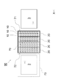
本発明に係る紫外線照射装置1は、図7Aに示すように、ランプハウス2内に、上記ランプ10とは別に、他のランプ(環境調整用ランプ40)を備える構成を排除しない。この環境調整用ランプ40は、ランプ10とは異なり、例えばランプハウス2内の温度を昇温する目的で設けられるものである。環境調整用ランプ40は、ランプ10と同じく、エキシマランプであっても構わないし、白熱ランプなどの他のランプであっても構わない。
環境調整用ランプ40は、ランプ10のように等間隔で配置される必要はない。例えば、図7Aに示すように、環境調整用ランプ40は、ランプハウス2内の出入口開口端21側や閉塞端23側に配置されていても構わない。更には、図示しないが、環境調整用ランプ40は、ランプハウス2内において、Y方向に関してランプ10とは別の位置に配置されていても構わない。
更に別の例として、図7Bに示すように、環境調整用ランプ40が、X方向に関してランプ10と等間隔で配置されていても構わない。この場合、X方向に配列された複数のランプ10群の最も外側に位置するランプが、環境調整用ランプ40として機能するものとしてもよい。
1 :紫外線照射装置
2 :ランプハウス
3 :ワーク
4 :搬送機構
5 :制御部
10 :ランプ
11 :発光管
12 :第一電極
13 :第二電極
14G :発光ガス
15 :電源部
20 :ランプユニット
21 :出入口開口端
22 :シャッター
23 :閉塞端
30 :不活性ガス源
31 :不活性ガス導入機構
32 :排気機構
40 :環境調整用ランプ
70 :ランプハウス
71 :端部
72 :端部
73 :退避エリア
90 :紫外線照射装置
L1 :紫外線
d10 :ランプの搬送方向に係る中心部同士の離間距離(ランプピッチ)
2 :ランプハウス
3 :ワーク
4 :搬送機構
5 :制御部
10 :ランプ
11 :発光管
12 :第一電極
13 :第二電極
14G :発光ガス
15 :電源部
20 :ランプユニット
21 :出入口開口端
22 :シャッター
23 :閉塞端
30 :不活性ガス源
31 :不活性ガス導入機構
32 :排気機構
40 :環境調整用ランプ
70 :ランプハウス
71 :端部
72 :端部
73 :退避エリア
90 :紫外線照射装置
L1 :紫外線
d10 :ランプの搬送方向に係る中心部同士の離間距離(ランプピッチ)
Claims (8)
- 搬送されるワークに対して紫外線を照射する紫外線照射装置であって、
前記ワークを搬送方向に搬送する搬送機構と、
前記紫外線を発する複数のランプが前記搬送方向に沿って実質的に等間隔に並べられてなるランプハウスと、
前記搬送機構の動作及び前記複数のランプの発光を制御する制御部とを備え、
前記ランプハウスは、前記紫外線の照射方向に見て前記ワークを内側に搬入するための出入口開口端と、前記搬送方向に関して前記出入口開口端とは反対側の閉塞端とを有し、
前記制御部は、
前記紫外線の照射方向に見て、前記ワークの全体が前記ランプハウスの内側に位置するまで、前記ワークを、前記出入口開口端から正の前記搬送方向に搬送する工程(a)と、
前記工程(a)の後、前記ワークの先端が前記閉塞端よりも外側に出ない範囲内で前記ワークを正の前記搬送方向に沿って搬送し、前記複数のランプと前記ワークとの相対的な位置を異ならせた状態で、前記複数のランプから前記紫外線を前記ワークに照射する工程(b)と、
前記工程(b)の実行後、前記ワークを前記工程(a)及び前記工程(b)とは逆向きである負の前記搬送方向に沿って搬送して、前記紫外線の照射方向に見て前記出入口開口端から前記ランプハウスの外側に前記ワークを出す工程(c)とを実行する制御を行い、
前記工程(b)によって前記ワークが正の前記搬送方向に移動される距離の合計が、前記搬送方向に隣接する1対の前記ランプの前記搬送方向に係る中心部同士の離間距離以内であることを特徴とする、紫外線照射装置。 - 前記工程(b)は、
前記工程(a)の実行後の前記ワークの位置において、前記紫外線を前記ワークに照射する工程(b1)と、
前記工程(b1)の実行後、前記複数のランプを消灯した状態で前記ワークを正の前記搬送方向に沿って搬送する工程(b2)と、
前記工程(b2)の実行後の前記ワークの位置において、前記紫外線を前記ワークに照射する工程(b3)とを有し、
前記工程(c)は、前記工程(b2)及び前記工程(b3)が1回ずつ又は複数回繰り返し実行された後、前記複数のランプを消灯した状態で実行されることを特徴とする、請求項1に記載の紫外線照射装置。 - 前記工程(c)は、前記工程(b2)及び前記工程(b3)が1回ずつ実行された後に、実行され、
前記工程(b2)は、前記搬送方向に隣接する1対の前記ランプの前記搬送方向に係る中心部同士の離間距離に対して、実質的に1/2の距離だけ搬送する工程であることを特徴とする、請求項2に記載の紫外線照射装置。 - 前記工程(c)は、前記工程(b2)及び前記工程(b3)の一連の処理が、それぞれn回(nは自然数)繰り返し実行された後に、実行され、
前記工程(b2)は、各回において、前記搬送方向に隣接する1対の前記ランプの前記搬送方向に係る中心部同士の離間距離に対して、実質的に1/(n+1)の距離だけ搬送する工程であることを特徴とする、請求項2に記載の紫外線照射装置。 - 前記工程(b)は、
前記工程(a)の実行後の前記ワークの位置において、前記複数のランプから前記紫外線を前記ワークに照射を開始する工程(b1)と、
前記複数のランプから前記紫外線を照射しながら、前記ワークを正の前記搬送方向に沿って、前記搬送方向に隣接する1対の前記ランプの前記搬送方向に係る中心部同士の離間距離以内だけ搬送する工程(b2)とを有し、
前記工程(c)は、前記工程(b2)の実行後に、前記複数のランプを消灯した状態で実行されることを特徴とする、請求項1に記載の紫外線照射装置。 - 前記工程(a)及び前記工程(c)は、前記工程(b2)よりも速い速度で前記ワークが搬送される工程であることを特徴とする、請求項5に記載の紫外線照射装置。
- 前記ランプハウスは、
所定数の前記ランプを収容するランプユニットが前記搬送方向に沿って複数配置されてなり、
前記ランプユニットに対応して配置され、前記ワークに対して不活性ガスを供給する複数の不活性ガス導入機構と、
前記ランプユニットに対応して配置され、前記ランプハウス内に存在する雰囲気ガスを前記ランプハウス外に排出する複数の排気機構とを備えることを特徴とする、請求項1~6のいずれか1項に記載の紫外線照射装置。 - 前記複数のランプのそれぞれは、断面が矩形状を呈した発光管と、前記発光管の前記ワーク側の管壁に形成された第一電極と、前記発光管の前記ワークとは反対側の管壁に形成された第二電極とを有し、
前記制御部は、前記工程(c)において、前記第一電極に対して前記第二電極が正電圧となる矩形状の電圧を、前記複数のランプのそれぞれに対して個別に印加する制御を行うことを特徴とする、請求項1~7のいずれか1項に記載の紫外線照射装置。
Applications Claiming Priority (2)
| Application Number | Priority Date | Filing Date | Title |
|---|---|---|---|
| JP2020-063342 | 2020-03-31 | ||
| JP2020063342A JP2021163842A (ja) | 2020-03-31 | 2020-03-31 | 紫外線照射装置 |
Publications (1)
| Publication Number | Publication Date |
|---|---|
| WO2021199801A1 true WO2021199801A1 (ja) | 2021-10-07 |
Family
ID=77930301
Family Applications (1)
| Application Number | Title | Priority Date | Filing Date |
|---|---|---|---|
| PCT/JP2021/007056 Ceased WO2021199801A1 (ja) | 2020-03-31 | 2021-02-25 | 紫外線照射装置 |
Country Status (2)
| Country | Link |
|---|---|
| JP (1) | JP2021163842A (ja) |
| WO (1) | WO2021199801A1 (ja) |
Citations (6)
| Publication number | Priority date | Publication date | Assignee | Title |
|---|---|---|---|---|
| JPH07183263A (ja) * | 1993-12-24 | 1995-07-21 | Dainippon Screen Mfg Co Ltd | 紫外線照射装置 |
| JP2003159571A (ja) * | 2001-11-27 | 2003-06-03 | Ushio Inc | 紫外線照射装置 |
| JP2007264194A (ja) * | 2006-03-28 | 2007-10-11 | Harison Toshiba Lighting Corp | 光化学処理装置及び光化学処理方法 |
| JP2008103556A (ja) * | 2006-10-19 | 2008-05-01 | Dainippon Screen Mfg Co Ltd | 基板処理方法および基板処理装置 |
| JP2011009238A (ja) * | 2010-09-22 | 2011-01-13 | Gs Yuasa Corp | 無声放電ランプおよび照射装置 |
| JP2018133451A (ja) * | 2017-02-15 | 2018-08-23 | ウシオ電機株式会社 | 光照射装置および光照射方法 |
-
2020
- 2020-03-31 JP JP2020063342A patent/JP2021163842A/ja active Pending
-
2021
- 2021-02-25 WO PCT/JP2021/007056 patent/WO2021199801A1/ja not_active Ceased
Patent Citations (6)
| Publication number | Priority date | Publication date | Assignee | Title |
|---|---|---|---|---|
| JPH07183263A (ja) * | 1993-12-24 | 1995-07-21 | Dainippon Screen Mfg Co Ltd | 紫外線照射装置 |
| JP2003159571A (ja) * | 2001-11-27 | 2003-06-03 | Ushio Inc | 紫外線照射装置 |
| JP2007264194A (ja) * | 2006-03-28 | 2007-10-11 | Harison Toshiba Lighting Corp | 光化学処理装置及び光化学処理方法 |
| JP2008103556A (ja) * | 2006-10-19 | 2008-05-01 | Dainippon Screen Mfg Co Ltd | 基板処理方法および基板処理装置 |
| JP2011009238A (ja) * | 2010-09-22 | 2011-01-13 | Gs Yuasa Corp | 無声放電ランプおよび照射装置 |
| JP2018133451A (ja) * | 2017-02-15 | 2018-08-23 | ウシオ電機株式会社 | 光照射装置および光照射方法 |
Also Published As
| Publication number | Publication date |
|---|---|
| JP2021163842A (ja) | 2021-10-11 |
Similar Documents
| Publication | Publication Date | Title |
|---|---|---|
| TWI877196B (zh) | 用於工件處理之感應耦合電漿中的增強點火及其方法 | |
| US20160018736A1 (en) | Light irradiating appatarus | |
| JP7304768B2 (ja) | 熱処理装置および熱処理装置の洗浄方法 | |
| JP4029613B2 (ja) | 閃光放射装置および光加熱装置 | |
| US20160221049A1 (en) | Light projection device | |
| US20030215751A1 (en) | Method of removing resist using functional water and device therefor | |
| KR20190001518A (ko) | 플라즈마 처리 장치 | |
| KR20190033003A (ko) | 파티클 제거 방법 및 열처리 장치 | |
| CN101199923A (zh) | 准分子光照射装置 | |
| JP2021163842A (ja) | 紫外線照射装置 | |
| KR20200097777A (ko) | 광조사 장치 | |
| CN102119237B (zh) | 对等离子体显示器面板的基板形成保护膜的方法以及该保护膜的形成装置 | |
| TW200822965A (en) | Excimer irradiation system | |
| JP6527733B2 (ja) | 熱処理装置 | |
| JP6135764B2 (ja) | デスミア処理装置 | |
| KR100935401B1 (ko) | 자외선을 이용하는 기판세정장치 및 이의 구동방법 | |
| US6734444B2 (en) | Substrate treatment device using a dielectric barrier discharge lamp | |
| JP3645031B2 (ja) | 基板処理装置 | |
| JP6683578B2 (ja) | 基板処理方法 | |
| JP2007264194A (ja) | 光化学処理装置及び光化学処理方法 | |
| TWI569300B (zh) | Lighting device | |
| JPH07185489A (ja) | 紫外線照射式改質装置 | |
| KR102703514B1 (ko) | 자외선 조사 장치 및 자외선 조사 방법 | |
| JP2002158203A (ja) | 基板の紫外線処理方法及び装置 | |
| JP7188221B2 (ja) | 液晶パネル製造装置 |
Legal Events
| Date | Code | Title | Description |
|---|---|---|---|
| 121 | Ep: the epo has been informed by wipo that ep was designated in this application |
Ref document number: 21779349 Country of ref document: EP Kind code of ref document: A1 |
|
| NENP | Non-entry into the national phase |
Ref country code: DE |
|
| 122 | Ep: pct application non-entry in european phase |
Ref document number: 21779349 Country of ref document: EP Kind code of ref document: A1 |