WO2021199285A1 - 断熱構造体の装着方法及び取り外し方法 - Google Patents
断熱構造体の装着方法及び取り外し方法 Download PDFInfo
- Publication number
- WO2021199285A1 WO2021199285A1 PCT/JP2020/014818 JP2020014818W WO2021199285A1 WO 2021199285 A1 WO2021199285 A1 WO 2021199285A1 JP 2020014818 W JP2020014818 W JP 2020014818W WO 2021199285 A1 WO2021199285 A1 WO 2021199285A1
- Authority
- WO
- WIPO (PCT)
- Prior art keywords
- heat insulating
- insulating member
- circumferential direction
- adjacent
- along
- Prior art date
Links
Images


Classifications
-
- F—MECHANICAL ENGINEERING; LIGHTING; HEATING; WEAPONS; BLASTING
- F16—ENGINEERING ELEMENTS AND UNITS; GENERAL MEASURES FOR PRODUCING AND MAINTAINING EFFECTIVE FUNCTIONING OF MACHINES OR INSTALLATIONS; THERMAL INSULATION IN GENERAL
- F16L—PIPES; JOINTS OR FITTINGS FOR PIPES; SUPPORTS FOR PIPES, CABLES OR PROTECTIVE TUBING; MEANS FOR THERMAL INSULATION IN GENERAL
- F16L59/00—Thermal insulation in general
- F16L59/14—Arrangements for the insulation of pipes or pipe systems
Definitions
- a plurality of heat insulating members are arranged side by side in the circumferential direction of a cylindrical or hollow spherical heat insulating object cooled by a low temperature fluid, and the plurality of heat insulating members cover the outer periphery of the heat insulating object.
- the present invention relates to a method of mounting a heat insulating structure that insulates a heat insulating object and a method of removing the heat insulating structure.
- the heat insulating structure covers the outer periphery of the heat insulating object with a hollow spherical storage tank for storing low temperature fluid such as LNG or a cylindrical pipe (cylindrical pipe) through which the low temperature fluid such as LNG flows as the heat insulating object.
- Insulation members are arranged side by side to insulate the heat insulating object. That is, it insulates the outer peripheral portion of the heat insulating object to be cooled by the presence of the low temperature fluid inside.
- the outer circumference of a cylindrical pipe as a heat insulating object is covered with a pair of semi-cylindrical heat insulating members, and a urethane foam foaming agent is filled in a joint portion of the pair of semi-cylindrical heat insulating members.
- Some semi-cylindrical heat insulating members are foamed and solidified to join the semi-cylindrical heat insulating members (see, for example, Patent Document 1).
- the semi-cylindrical heat insulating member is mounted while performing the troublesome filling work of the urethane foam foaming agent, the mounting work of the semi-cylindrical heat insulating member becomes a troublesome work, and also for heat insulation. Since it is necessary to cut the thick semi-cylindrical heat insulating member, the work of removing the semi-cylindrical heat insulating member is troublesome and troublesome. Moreover, since the semi-cylindrical heat insulating member is cut and removed, it is difficult to reuse the semi-cylindrical heat insulating member.
- the connecting portion of the pair of semi-cylindrical heat insulating members is foamed with urethane foam. It is conceivable that they are not joined with an agent, but in this case, a gap is formed between the pair of semi-cylindrical heat insulating members, and there is a problem that the piping cannot be well insulated in this gap. ..
- the present invention has been made in view of the above circumstances, and an object of the present invention is to attach a heat insulating member capable of satisfactorily insulating an object to be insulated and facilitating the mounting work of the heat insulating member.
- the point is to provide a method.
- Another object of the present invention is to provide a method for removing the heat insulating member, which can facilitate the work of removing the heat insulating member and can reuse the heat insulating member.
- a plurality of heat insulating members are arranged side by side in the circumferential direction of a cylindrical or hollow spherical heat insulating object cooled by a low temperature fluid, and the heat insulating object is provided with the plurality of heat insulating members. It is a method of mounting a heat insulating structure that insulates the heat insulating object while covering the outer periphery of the heat insulating object.
- a recessed groove portion that is recessed in the circumferential direction from the facing end face is groove-shaped along the longitudinal direction of the heat insulating member and is formed on the end face of the heat insulating member facing the other heat insulating member adjacent to the heat insulating member.
- a wide portion that is wider in the thickness direction than the opening width of the heat insulating member along the thickness direction of the inlet portion is formed in advance so as to be provided on the inner portion side along the circumferential direction.
- a state in which a long connecting member along the longitudinal direction of the heat insulating member includes a pair of engaging portions that engage with the recessed groove portions of each of the heat insulating members adjacent to the circumferential direction along the circumferential direction.
- the heat insulating member adjacent to the heat insulating member in the circumferential direction is arranged on the outer peripheral portion of the heat insulating object in a state where the facing end faces are butted against each other. The point is that the insertion step of inserting the connecting member into the recessed groove portion of each of the adjacent heat insulating members is sequentially performed.
- the recessed groove portion that is recessed in the circumferential direction of the heat insulating object from the facing end face on the end face facing the heat insulating member adjacent to the heat insulating member in the circumferential direction is a groove shape along the longitudinal direction of the heat insulating member.
- a wide portion that is wider in the thickness direction than the opening width along the thickness direction of the heat insulating member at the entrance portion is formed in advance so as to be provided on the inner portion side along the circumferential direction.
- the heat insulating member adjacent to the heat insulating object in the circumferential direction is arranged on the outer peripheral portion of the heat insulating object with the facing end faces abutting against each other.
- the insertion step of inserting the connecting member into the recessed groove portion of each of the adjacent heat insulating members is sequentially performed.
- the heat insulating members adjacent to the heat insulating object in the circumferential direction are connected by the connecting member, and between the facing end faces of the adjacent heat insulating members. Since the connecting member is located at the center, it is possible to avoid the formation of a gap between the adjacent heat insulating members, so that the heat insulating object can be well heat-insulated.
- the heat insulating member is attached to the heat insulating object by inserting the connecting member into the recessed groove of the heat insulating member arranged on the outer peripheral portion of the heat insulating object, the heat insulating member can be easily attached. Can be achieved.
- a further characteristic configuration of the method for mounting the heat insulating structure of the present invention is that the heat insulating object is a cylindrical tube through which the low temperature fluid passes.
- the heat insulating member has a plate shape extending along the axial direction of the cylindrical tube and an arc-shaped curved plate shape in the axial direction.
- the cylindrical tube as a heat insulating object can be well heat-insulated.
- a further characteristic configuration of the method for mounting the heat insulating structure of the present invention is that the heat insulating members are provided in a state where three or more of the heat insulating members are lined up along the circumferential direction. Before mounting the heat insulating member on the cylindrical tube, some of the heat insulating members are positioned so that the heat insulating members adjacent to each other in the circumferential direction are abutted against each other. Then, a pre-assembly step of inserting the connecting member into the recessed groove portion of each of the adjacent heat insulating members is performed, and the set of the heat insulating members assembled in the pre-assembling step is assembled in the arranging step. It is at the point of arranging.
- a heat insulating member adjacent to each other in the circumferential direction is placed on a mounting surface such as the ground in a standing posture, and a connecting member is inserted into the recessed groove portion of the heat insulating member from above. It can be performed as a simple work by making it work.
- the heat insulating members provided in a state where three or more are arranged along the circumferential direction, there is a set of heat insulating members that are previously connected by the connecting members in the pre-assembly process. Since the set of the heat insulating members can be arranged on the outer peripheral portion of the cylindrical tube in the above-mentioned arrangement step and the heat insulating members can be mounted in a state where three or more heat insulating members are lined up along the circumferential direction, the mounting work can be facilitated. can.
- a further characteristic configuration of the method for mounting the heat insulating structure of the present invention is to mount another heat insulating member on the outer peripheral portion of the heat insulating member previously mounted as the heat insulating member in the radial direction of the cylindrical tube.
- a plurality of types of heat insulating members having different radii of curvature are provided.
- a plurality of types of the heat insulating member are mounted in a form in which the heat insulating member having a smaller radius of curvature is mounted first.
- the heat insulating member a plurality of types of heat insulating members having different radii of curvature are formed in order to form a plurality of heat insulating layers in the radial direction of the cylindrical tube in a form in which another heat insulating member is mounted on the outer peripheral portion of the heat insulating member previously mounted. Is provided.
- a plurality of heat insulating layers are formed by mounting a plurality of types of heat insulating members in a form in which the heat insulating member having a smaller radius of curvature is mounted first. be able to. Therefore, since the cylindrical tube can be covered with a plurality of heat insulating layers, the cylindrical tube can be more appropriately insulated.
- the cylindrical tube can be more appropriately heat-insulated.
- a further characteristic configuration of the method for mounting the heat insulating structure of the present invention is that the recessed groove portion is formed in at least a part of the heat insulating layer on the inner side of the plurality of heat insulating layers without forming the recessed groove portion. The point is that the heat insulating member is arranged without inserting the connecting member.
- the cylindrical tube when the cylindrical tube is covered with a plurality of heat insulating layers, at least a part of the heat insulating layer on the inner side of the plurality of heat insulating layers is provided with a connecting member in the recessed groove portion without forming the recessed groove portion. Place the insulation member without inserting it. That is, in view of the fact that the inner heat insulating layer of the plurality of heat insulating layers is covered with the outer heat insulating layer and maintained in an appropriate posture, the inner side of the plurality of heat insulating layers is maintained. For at least a part of the heat insulating layer on the side, the heat insulating member is arranged without forming the recessed groove portion and without inserting the connecting member into the recessed groove portion.
- the recessed groove portion is not formed and the connecting member is not inserted into the recessed groove portion. Therefore, the recessed groove portion is formed. It is possible to save the trouble of performing the work, reduce the consumption of the connecting member, and simplify and reduce the cost of the heat insulating structure.
- the heat insulating structure can be simplified and reduced in cost.
- a further characteristic configuration of the method for mounting the heat insulating structure of the present invention is that the facing portion of the heat insulating member adjacent to the heat insulating member in the circumferential direction is positioned so that the facing end faces thereof are abutted against each other, among the plurality of heat insulating layers.
- the heat insulating member is arranged so as to have different phases in the circumferential direction in the heat insulating layer adjacent to the radial direction.
- the facing portions positioned so that the facing end faces of the heat insulating members adjacent to each other in the circumferential direction are butted against each other are adjacent to each other in the radial direction among the plurality of heat insulating layers.
- the heat insulating member is arranged so as to have different phases in the circumferential direction in the heat insulating layer.
- the facing portions positioned so that the facing end faces of the heat insulating members adjacent to each other in the circumferential direction are butted against each other have different phases in the circumferential direction. Therefore, the non-opposing portion of the heat insulating member of the other heat insulating layer is located at the facing portion of the heat insulating member adjacent in the circumferential direction. Can be secured appropriately.
- a further characteristic configuration of the method for mounting the heat insulating structure of the present invention is a circumferential recessed portion in which the recessed groove portion is recessed from the inlet portion along the circumferential direction, and an end of the circumferential recessed portion. It is a form including a radial recessed portion that is recessed outward in the radial direction as the wide portion from the portion.
- a long connecting member along the longitudinal direction of the heat insulating member includes a pair of locking protrusions that engage with the locking recesses of each of the heat insulating members adjacent to the circumferential direction along the circumferential direction.
- the locking recess is engaged with the connecting member arranged in advance. ..
- the circumferential recessed portion in which the recessed groove portion is recessed along the circumferential direction from the inlet portion and the radial direction in which the recessed groove portion is recessed outward in the radial direction as a wide portion from the end portion of the circumferential recessed portion It is formed in a form including a recessed portion.
- the locking recess of the heat insulating member is engaged with the connecting member arranged in advance. Insulating members that are adjacent to each other in the circumferential direction are mounted so as to be aligned so that the facing end faces are butted against each other. That is, even when the connecting member cannot be inserted due to the position of the flange connecting the cylindrical tube, a heat insulating member having a locking recess is attached to the outer peripheral portion of the cylindrical tube to insulate the cylindrical tube. be able to.
- the heat insulating member having the recessed groove is used on the outer peripheral portion of the cylindrical tube.
- a heat insulating member can be attached to insulate the cylindrical tube.
- a further characteristic configuration of the method for mounting the heat insulating structure of the present invention is that the connecting member or the shaping jig is inserted into the recessed groove portion of each of the adjacent heat insulating members before the insertion step is performed. Perform the process,
- the shaping jig has the same cross-sectional shape as the connecting member, is longer than the connecting member, and has at least a surface harder than the surface of the connecting member.
- the shaping step of inserting the connecting member or the shaping jig into the recessed groove portion of each of the adjacent heat insulating members is performed before performing the insertion step of inserting the connecting member into the recessed groove portion of each of the adjacent heat insulating members.
- the connecting member can be satisfactorily inserted into the recessed groove portion of each of the adjacent heat insulating members.
- the orthopedic jig has the same cross-sectional shape as the connecting member, is longer than the connecting member, and has at least a surface harder than the surface of the connecting member.
- the connecting member since the shape of the recessed groove portion is slightly different from the normal shape due to a manufacturing error or the like, it may be difficult to insert the connecting member into the recessed groove portion of each of the adjacent heat insulating members. However, by performing the shaping step, the connecting member can be satisfactorily inserted into the recessed groove portion of each of the adjacent heat insulating members.
- the shaping step may be performed before the insertion step, but when the insertion step is performed and it is difficult to insert the connecting member into the recessed groove portion of the adjacent heat insulating member, the shaping step may be performed. It may be carried out by a procedure for performing a shaping process.
- the connecting member can be satisfactorily inserted into the recessed groove portion of the adjacent heat insulating member.
- a plurality of heat insulating members are arranged side by side in the circumferential direction of a cylindrical or hollow spherical heat insulating object cooled by a low temperature fluid, and the heat insulating object is formed by the plurality of heat insulating members. It is a method of removing a heat insulating structure that insulates the heat insulating object while covering the outer periphery of the heat insulating object.
- a recessed groove portion that is recessed in the circumferential direction from the facing end face is groove-shaped along the longitudinal direction of the heat insulating member and is formed on the end face of the heat insulating member facing the other heat insulating member adjacent to the heat insulating member.
- a recessed groove portion that is recessed in the circumferential direction of the heat insulating object from the facing end face is formed in a groove shape along the longitudinal direction of the heat insulating member.
- a wide portion that is wider in the thickness direction than the opening width along the thickness direction of the heat insulating member at the entrance portion is formed in a state of being provided on the inner portion side along the circumferential direction.
- a state in which a long connecting member along the longitudinal direction of the heat insulating member is provided with a pair of engaging portions that engage with the recessed grooves of the heat insulating member adjacent to each other in the circumferential direction of the heat insulating object along the circumferential direction. Is formed in.
- the heat insulating members adjacent to each other in the circumferential direction are arranged on the outer peripheral portion of the heat insulating object in a state where the facing end faces are butted against each other, and the connecting member is attached to the adjacent heat insulating member. It is in the form of being inserted into the recessed groove. That is, the heat insulating member is arranged on the outer peripheral portion of the heat insulating object so that the facing end faces are butted against each other, and the connecting member is inserted into the recessed groove portion of the adjacent heat insulating member.
- the object will be insulated.
- a cutting step of cutting the portion connecting the pair of engaging portions in the connecting member along the facing end faces and a detaching step of separating the heat insulating member from the heat insulating object Will be performed in sequence.
- a cutter is inserted between the facing end faces of the heat insulating members adjacent to each other in the circumferential direction, and the cutter is moved along the facing end faces to face the portions connecting the pair of engaging portions in the connecting member.
- the process can be a process of cutting along the end face, and the connecting member having a thickness thinner than the heat insulating member can be easily cut by the cutter, and the cutter can be guided by the facing end face, so that the cutter is opposed to the other. Since it can be moved satisfactorily along the end face, the cutting step can be easily performed.
- the connecting member is divided into two, and the connection by the connecting member to the heat insulating member adjacent in the circumferential direction is released. Therefore, the detaching step of removing the heat insulating member from the heat insulating object can be easily performed.
- the cut connecting member remains in the heat insulating member separated from the heat insulating object, and the remnant of this connecting member is inserted into the recessed groove portion through, for example, the inlet portion of the recessed groove portion.
- the heat insulating member can be easily removed from the heat insulating member without being damaged while being handled through the inlet portion of the recessed groove portion, such as by pushing out with a pressing tool, and as a result, the heat insulating member can be reused.
- the work of removing the heat insulating member can be facilitated, and the heat insulating member can be reused.
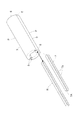
- FIG. 6 is a view taken along the line IV-IV in FIG. It is an exploded perspective view which shows the relationship between a connecting member and a heat insulating member. It is a front view which shows the recessed groove part in a heat insulating member. It is a front view which shows the connecting member. It is a VIII-VIII line arrow view in FIG. 1. It is a front view which shows the mounting procedure of the heat insulation member for an end part.
- FIG. 1 It is an enlarged perspective view of a part of a connecting member. It is a perspective view which shows the relationship between a connecting member and a shaping jig. It is a front view which shows the removal procedure of a heat insulating member. It is a front view which shows the mounting state of the heat insulating member of another embodiment. It is a front view which shows the mounting state of the heat insulating member of another embodiment. It is a front view which shows the mounting state of the end insulation member of another embodiment. It is a front view which shows another form of the recessed groove part. It is a front view which shows the further other form of the recessed groove part. It is a front view which shows another form of a connecting member.
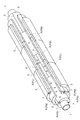
- FIGS. 1 and 2 a cylindrical cylindrical tube 1 (an example of a heat insulating object) through which a low-temperature fluid such as LNG or LPG flows and is cooled is provided, and urethane is provided on the outer peripheral portion of the cylindrical tube 1.
- a plurality of heat insulating members P made of urethane foam in which resin is foamed are mounted in a state of being lined up in the circumferential direction and the axial direction of the cylindrical tube 1.
- the plurality of heat insulating members P have a plate shape extending along the axial direction of the cylindrical tube 1 and an arc-shaped curved plate shape in the axial direction of the cylindrical tube 1. That is, the heat insulating member P has an arc shape (semi-circular shape in the present embodiment) along the circumferential direction of the cylindrical tube 1 in a state of having a constant thickness in the radial direction of the cylindrical tube 1, and is in the axial direction of the cylindrical tube 1. A base material formed in a long shape having a long length is cut to a predetermined length in the axial direction of the cylindrical tube 1.
- the radial outer surface of the heat insulating member P is the outer surface 3
- the radial inner surface is the inner surface 4
- the surfaces at both ends in the circumferential direction are the facing end surfaces 5.
- the surfaces on both sides in the axial direction are referred to as side surfaces 6.
- the reason why the surfaces at both ends in the circumferential direction are called the facing end faces 5 is that the heat insulating members P are arranged in a state where the surfaces at both ends in the circumferential direction of the pair of heat insulating members P adjacent to each other in the circumferential direction of the cylindrical tube 1 are butted against each other. Because it is done.
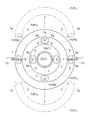
- the heat insulating member P a plurality of heat insulating members P are mounted in the radial direction of the cylindrical tube 1 (three layers in the present embodiment) in a form in which another heat insulating member P is mounted on the outer peripheral portion of the heat insulating member P previously mounted.
- a plurality of types of heat insulating members P having different radii of curvature are provided. Then, the heat insulating member P is attached so as to form three heat insulating layers along the radial direction of the cylindrical tube 1.
- the large-diameter large-diameter heat insulating member PL, the medium-diameter heat-insulating member PM, and the small-diameter heat-insulating member having the smallest diameter. PS is provided (see FIGS. 3 and 4).
- the outer surface 3 of the large diameter heat insulating member PL is located on the outermost side, and the inner surface 4 of the large diameter heat insulating member PL and the outer surface 3 of the intermediate diameter heat insulating member PM have the same diameter.
- the inner surface 4 of the intermediate diameter heat insulating member PM and the outer surface 3 of the small diameter heat insulating member PS are arranged in the same diameter, and the inner surface 4 of the small diameter heat insulating member PS is arranged in the same diameter as the outer peripheral surface of the cylindrical tube 1. become.
- flanges F are provided at both ends of the cylindrical pipe 1, and the flanges F of the adjacent cylindrical pipe 1 are connected by using bolts to form a flow path for flowing a low temperature fluid. Will be done.
- the plurality of heat insulating members P are sequentially mounted from one end (left end in FIG. 1) to the other end (right end in FIG. 1) of the cylindrical tube 1 and are adjacent to one end of the cylindrical tube 1. It will be mounted at a location, a location adjacent to the other end of the cylindrical tube 1, and a location corresponding between them.
- the form in which the heat insulating members P are arranged in the axial direction of the cylindrical tube 1 is the same as the form in which the smallest diameter small diameter heat insulating member PS is arranged and the form in which the largest diameter large diameter heat insulating member PL is arranged.
- the form of arranging the intermediate diameter heat insulating members PM with different diameters is different. That is, the small-diameter heat insulating member PS, the intermediate-diameter heat insulating member PM, and the large-diameter heat insulating member PL are formed so that the length along the axial direction of the cylindrical tube 1 is the basic length (for example, 1 m).
- the heat insulating members P having the basic length are arranged from one end to the other end of the cylindrical tube 1, whereas for the intermediate diameter heat insulating member PM, the heat insulating member P has a basic length.
- the heat insulating member P having a length of half the basic length (for example, 0.5 m) at one end of the cylindrical tube 1 is directed toward the other end of the cylindrical tube 1. It is configured to be arranged side by side (see FIG. 1).
- the axial lengths of the small-diameter heat insulating member PS, the intermediate-diameter heat insulating member PM, and the large-diameter heat insulating member PL become the axial length of the cylindrical tube 1. It will be decided as appropriate. However, the length of the small diameter heat insulating member PS, the intermediate diameter heat insulating member PM, and the large diameter heat insulating member PL mounted at the positions adjacent to the other end of the cylindrical tube 1 in the axial direction is the space for mounting the connecting member 7, which will be described later. Is configured to have a length of 1 m or more between the flange F and the flange F.
- the intermediate diameter heat insulating member PM since the intermediate diameter heat insulating member PM having a length of half the basic length (for example, 0.5 m) is installed at a position adjacent to one end of the cylindrical tube 1, the cylindrical tube 1
- the length of the intermediate diameter heat insulating member PM in the axial direction is different from the length of the small diameter heat insulating member PS and the large diameter heat insulating member PL in the axial direction at a portion adjacent to the other end portion of the above.
- the length of the intermediate diameter heat insulating member PM in the axial direction is half the basic length of the small diameter heat insulating member PS and the large diameter heat insulating member PL in the axial direction (for example, 0.5 m). The length is added to the length of.
- the heat insulating members P are mounted side by side in the circumferential direction of the cylindrical tube 1 at an intermediate portion excluding a portion adjacent to one end of the cylindrical tube 1 and a portion adjacent to the other end of the cylindrical tube 1 (hereinafter, basic).
- the configuration (abbreviated as mounting configuration) is the same, but the configuration in which the heat insulating members P are arranged side by side in the circumferential direction of the cylindrical tube 1 at a position adjacent to the other end of the cylindrical tube 1 (hereinafter, abbreviated as the end mounting configuration) is used.
- the configuration is different from the basic mounting configuration.
- the heat insulating member P is mounted in the basic mounting configuration using the connecting member 7 described later, and is adjacent to the other end of the cylindrical tube 1. In the place where the heat insulating member P is mounted, the heat insulating member P is mounted in the end mounting configuration using the connecting member B described later.
- the basic mounting configuration and the end mounting configuration will be described in sequence.
- the portion between the flange F of the cylindrical tube 1 and the heat insulating member P is filled with a heat insulating material D such as glass wool, and the portion corresponding to the upper part of the flange F of the cylindrical tube 1 is basically mounted.
- the arc-shaped flange heat insulating member Q is installed in two layers.
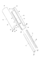
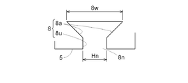
- the recessed groove portion 8 that is recessed in the circumferential direction from the facing end surface 5 is formed in the end surface portion of the heat insulating member P that faces the other heat insulating member P adjacent to the cylindrical tube 1 in the circumferential direction.
- a wide portion 8w that has a groove shape along the longitudinal direction of the heat insulating member P and is wider in the thickness direction than the opening width Hn along the thickness direction of the heat insulating member P of the inlet portion 8n is placed on the inner side along the circumferential direction. It is pre-formed to be ready.
- the thickness direction of the heat insulating member P corresponds to the radial direction of the cylindrical tube 1, and the thickness direction is hereinafter referred to as the radial direction. Further, the longitudinal direction of the heat insulating member P is a direction corresponding to the axial direction of the cylindrical tube 1.
- the recessed groove portion 8 has a circumferential recessed portion 8u that is linearly recessed from the inlet portion 8n along the circumferential direction, and a wide portion 8w from the end of the circumferential recessed portion 8u. It is formed in a form including a radial recessed portion 8a that is linearly recessed outward in the radial direction for formation. That is, in the present embodiment, the recessed groove portion 8 is formed in an L-shape.
- the circumferential direction of the cylindrical tube 1 means, to be exact, the tangential direction at the facing end surface 5 of the heat insulating member P, and the same applies to the following description.
- the circumferential recessed portion 8u and the radial recessed portion 8a are formed to have a C-shape by being curved as a whole.
- Various shapes are conceivable.
- Another form of the recessed groove portion 8 will be described later.
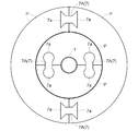
- the elongated connecting member 7 along the longitudinal direction of the heat insulating member P extends in the circumferential direction to the main body portion 7A and the recessed groove portions of the heat insulating member P adjacent to each other in the circumferential direction.
- a pair of engaging portions 7a that engage with 8 are formed in advance so as to be provided along the circumferential direction.
- the length of the connecting member 7 is formed to be the same as the length of the heat insulating member P in the axial direction, and the connecting member 7 is made of urethane resin like the heat insulating member P.
- the arc-shaped (semi-circular in the present embodiment) heat insulating member P divided into a plurality of (two in the present embodiment) in the circumferential direction of the cylindrical tube 1. are arranged in a state where the facing end faces 5 are butted against each other, and a pair of adjacent facing portions of the plurality of facing end faces 5 (two in the present embodiment) located in the circumferential direction of the cylindrical tube 1 are adjacent to each other.
- the heat insulating member P is attached to the outer peripheral portion of the cylindrical tube 1 by connecting the opposing ends of the heat insulating member P with a long connecting member 7 along the axial direction of the cylindrical tube 1.
- the heat insulating members P adjacent to each other in the circumferential direction are in a state where the facing end faces are butted against each other.
- the arrangement step of arranging the cylindrical tube 1 on the outer peripheral portion and the insertion step of inserting the connecting member 7 into the recessed groove portions 8 of the adjacent heat insulating member P are sequentially performed. Further, when the heat insulating member P is mounted on the outer peripheral portion of the cylindrical tube 1, a plurality of types of heat insulating members P are mounted in such a form that the heat insulating member P having a smaller radius of curvature among the heat insulating members P is mounted first. ..
- the small diameter heat insulating member PS is mounted on the outer peripheral surface of the cylindrical tube 1
- the intermediate diameter heat insulating member PM is mounted on the outer peripheral surface of the small diameter heat insulating member PS
- the large diameter heat insulating member PL is mounted.
- It will be mounted on the outer peripheral surface of the intermediate diameter heat insulating member PM.
- a plurality of arcs (two) connected to the outer peripheral portion of the cylindrical tube 1 by the connecting member 7.
- a plurality (three) heat insulating layers formed in a cylindrical shape and having different diameters are formed by the heat insulating member P (semicircular).
- the facing portion of the small diameter heat insulating member PS in which the facing end faces are butted against each other and the facing portion of the intermediate diameter heat insulating member PM in which the facing end faces are butted against each other have a phase of 90 in the circumferential direction of the cylindrical tube 1.
- the facing portion of the intermediate filament heat insulating member PM in which the facing end faces are butted against each other and the facing portion of the large diameter heat insulating member PL in which the facing end faces are butted against each other are the cylindrical pipe 1.
- the small-diameter heat insulating member PS, the intermediate-diameter heat-insulating member PM, and the large-diameter heat-insulating member PL are mounted in a form in which the phases in the circumferential direction are different by 90 degrees.
- a plurality of (three) heat insulating layers are provided with facing portions that are positioned so that the facing end faces of the heat insulating members P adjacent to each other in the circumferential direction are butted against each other.
- the heat insulating member P is arranged so as to have different phases in the circumferential direction in the heat insulating layer adjacent to the radial direction.
- a sheet covering the outer periphery of the laminated heat insulating member P is attached to reinforce the laminated heat insulating member P and improve the heat insulating property.
- a pair of locking convex portions Ba in which a long connecting member B along the longitudinal direction of the heat insulating member P engages with each locking recess V of the heat insulating member P adjacent in the circumferential direction. Is provided in advance in a state of being provided along the circumferential direction.
- the length of the connecting member B is formed to be the same as the length in the axial direction of the heat insulating member P, and the connecting member B is made of urethane resin like the heat insulating member P.
- the small-diameter heat insulating member PS (end heat insulating member PA) is attached to the outer peripheral surface of the cylindrical tube 1 while engaging the connecting member B arranged on the outer peripheral surface of the cylindrical tube 1 with the locking recess V.
- the intermediate diameter heat insulating member PM (end heat insulating member PA) is attached to the small diameter heat insulating member PS.
- the large-diameter heat-insulating member PL (end-diameter heat-insulating member PA) is attached to the outer surface 3 and finally engaged with the connecting member B arranged on the outer surface 3 of the intermediate-diameter heat-insulating member PM with the locking recess V. It will be mounted on the outer surface 3 of the intermediate diameter heat insulating member PM.
- the connecting member B When arranging the connecting member B on the outer peripheral surface of the cylindrical tube 1 or the outer surface 3 of the heat insulating member P laminated earlier, the bottom surface of the connecting member B in contact with the outer peripheral surface of the cylindrical tube 1 or the outer surface 3 of the heat insulating member P is provided. , The outer peripheral surface of the cylindrical tube 1 and the outer surface 3 of the heat insulating member P are machined. Further, when arranging the connecting member B on the outer peripheral surface of the cylindrical tube 1 or the outer surface 3 of the heat insulating member P laminated earlier, the location where the connecting member B is arranged is the outer peripheral surface of the cylindrical tube 1 or the heat insulating member P laminated earlier. In the case where the outer surface 3 is in a lateral position or a lower position, the connecting member B may be temporarily fixed by using a glue.
- the small-diameter heat-insulating member PS, the intermediate-diameter heat-insulating member PM, and the large-diameter heat-insulating member PL as the end heat insulating member PA are mounted, they are connected to the outer peripheral portion of the cylindrical tube 1 by the connecting member 7. It is provided in a state where a plurality of (three) heat insulating layers formed in a cylindrical shape and having different diameters are formed by the plurality of arcuate (two semicircular) heat insulating members P to be formed. ..
- a sheet covering the outer periphery of the laminated heat insulating member P is attached to reinforce the laminated heat insulating member P and improve the heat insulating property.
- a shaping jig R having the same cross-sectional shape as the connecting member 7, which is longer than the connecting member 7 and whose surface is at least harder than the surface of the connecting member 7, is provided.
- the shaping jig R is formed by using a urethane resin having a hardness higher than that of the urethane resin for producing the connecting member 7 and the heat insulating member P, and the entire shaping jig R is a connecting member. It is configured to be harder than 7.
- the connecting member 7 is connected to the recessed groove 8 of each of the adjacent heat insulating members P. It is configured to perform a shaping step of inserting the member 7 or the shaping jig R.
- this shaping step may be performed without fail before performing the inserting step of inserting the connecting member 7, but when it is difficult to insert the connecting member 7 when the inserting step is performed, the shaping step is performed. It may be performed by the procedure of performing.
- the heat insulating member P adjacent to each other in the circumferential direction is arranged on the outer peripheral portion of the cylindrical tube 1 in a state where the facing end faces are butted against each other, and the connecting member 7 is inserted into the recessed groove portion 8 of each of the adjacent heat insulating member P.
- a cutting step (shown by a solid line in the figure) of cutting a portion of the connecting member 7 connecting the pair of engaging portions 7a along the facing end faces, and the heat insulating member P being formed by the cylindrical tube 1
- the separation step (indicated by a virtual line in the figure) to separate from is sequentially performed. Specifically, the cutter 10 is inserted between the facing end faces 5 of the adjacent heat insulating member P, and the cutter 10 is moved in the axial direction of the cylindrical tube 1 through the facing end faces 5 of the adjacent heat insulating member P. As a result, a cutting step is performed, and the cutting step causes a disconnection step of separating the heat insulating member P, which has been disconnected by the connecting member 7, from the cylindrical tube 1.
- the small diameter heat insulating member PS, the intermediate diameter heat insulating member PM, and the large diameter heat insulating member PL are mounted. Therefore, first, as shown in FIG. 12, two connecting members 7 for the large diameter heat insulating member PL.
- the large diameter heat insulating member PL is removed by cutting along the facing end face 5, and then, although not shown, the two connecting members 7 for the intermediate diameter heat insulating member PM are cut along the facing end face 5.
- the intermediate diameter heat insulating member PM is removed, and finally, although not shown, the two connecting members 7 for the small diameter heat insulating member PS are cut along the facing end faces 5 to remove the small diameter heat insulating member PS.
- each of the removed heat insulating members P has a remaining portion Z corresponding to half of the cut connecting member 7.
- an extruder for pushing out the remaining portion Z is used in the recessed groove portion 8.
- the remaining portion Z may be removed while handling the remaining portion Z through the inlet portion 8n of the recessed groove portion 8, such as removing the remaining portion Z while moving the remaining portion Z through the inlet portion 8n.
- a portion located on the radial inward side of the recessed groove portion 8 in the end face portion of the heat insulating member P may be cut off.
- the cut portion J may be cut off. Since the locking recess V that is recessed outward in the radial direction is formed on the outer side portion in the radial direction of the above, the heat insulating member P is used as the heat insulating member PA for the end portion.
- the connecting member 7 when forming the three heat insulating layers, the connecting member 7 is inserted into the adjacent heat insulating member P constituting each heat insulating layer so that the adjacent heat insulating member P is connected. Configured. Instead, as shown in FIG. 13, when forming the three heat insulating layers, for example, for the innermost heat insulating layer, the connecting member 7 is not inserted into the adjacent small diameter heat insulating member PS. In addition, the adjacent small-diameter heat insulating member PS may be configured not to be connected.
- the heat insulating member P is arranged without forming the recessed groove portion 8 and without inserting the connecting member 7 into the recessed groove portion 8.
- the outer diameter of the cylindrical tube 1 is about 30 mm, whereas in this further embodiment, for example, the outer diameter of the cylindrical tube 1 is a large diameter of about 300 mm. Therefore, the heat insulating member P is formed in an arc shape of 90 degrees.
- the end mounting configuration is performed in the form of arranging the four end heat insulating members PA in the circumferential direction
- the four end heat insulating members are heat-insulated.
- Two of the member PAs may be pre-assembled, and then two pre-assembled end heat insulating member PAs may be assembled to the connecting member B.
- the recessed groove portion 8 is formed around a wide portion 8w that has a groove shape along the longitudinal direction of the heat insulating member P and is wider in the thickness direction than the opening width Hn along the thickness direction of the heat insulating member P of the inlet portion 8n.
- it may be configured in another form shown in FIG. 16 or a further other form shown in FIG.
- a circumferential recessed portion 8u in which the recessed groove portion 8 is recessed from the inlet portion 8n along the circumferential direction and the circumferential recessed portion 8u are used. It is formed in a form including two radial recessed portions 8a that are recessed outward in the radial direction and inward in the radial direction in order to form the wide portion 8w from the end portion of the above.
- the two radial recessed portions 8a are triangular, and in the further alternative form shown in FIG. 17, the two radial recessed portions 8a are circular.
- the recessed groove portion 8 is a radial recessed portion 8a that is recessed outward in the radial direction in order to form the wide portion 8w.
- the connecting member 7 In forming the connecting member 7 so as to include a main body portion 7A extending in the circumferential direction and a pair of engaging portions 7a that engage with the radial recessed portion 8a, the recessed groove portion 8 is separated as shown in FIG.
- the radial recessed portion 8a When the shape is formed, the radial recessed portion 8a has a triangular shape, and when the radial recessed portion 8a is formed into a different shape, the radial recessed portion 8a has a circular shape.
- the heat insulating member P, the connecting member 7, and the connecting member B are made of the same material, but the present invention is not limited to this, and the connecting member B, the connecting member 7, and the heat insulating member P are made of different materials. May be formed with.
- the material of the heat insulating member P is urethane resin, but the material of the heat insulating member P is not limited to this.
- the material of the heat insulating member P may be polyethylene resin, (polyisocinulate (PIR), or the like.
- the heat insulating object is the cylindrical tube 1, but the heat insulating object is not limited to this.
- the heat insulating object may be composed of a hollow spherical storage tank for storing a low-temperature fluid W such as LNG inside.
Landscapes
- Engineering & Computer Science (AREA)
- General Engineering & Computer Science (AREA)
- Mechanical Engineering (AREA)
- Thermal Insulation (AREA)
Abstract
断熱対象物を良好に断熱することができ、しかも、断熱部材の装着作業の容易化を図ることができる断熱構造体の装着方法を提供する。断熱部材(P)の断熱対象物(1)の周方向に隣接する他の断熱部材(P)に対向する端面部に、当該対向端面から周方向に凹入する凹入溝部(8)が予め形成され、断熱部材(P)の長手方向に沿う長尺状の接続部材(7)が、周方向に隣接する断熱部材(P)夫々の凹入溝部(8)に係合する一対の係合部(7a)を周方向に沿って備える状態に予め形成され、断熱部材(P)を断熱対象物(1)に装着する際に、周方向に隣接させる断熱部材(P)を、対向端面同士を突き合せた状態で断熱対象物(1)の外周部に配置する配置工程、及び、隣接する断熱部材(P)夫々の凹入溝部(8)に対して接続部材(7)を挿入する挿入工程を順次行う。
Description
本発明は、低温流体により冷却される円筒状又は中空球状の断熱対象物の周方向に複数の断熱部材を並設して、前記複数の断熱部材により前記断熱対象物の外周を覆う状態で前記断熱対象物を断熱する断熱構造体の装着方法及び断熱構造体の取り外し方法に関する。
断熱構造体は、LNG等の低温流体を貯留する中空球状の貯留槽又はLNG等の低温流体が流れる円筒状の配管(円筒管)を断熱対象物として、当該断熱対象物の外周を覆う状態で断熱部材を並設して、断熱対象物を断熱するものである。つまり、低温流体が内部に存在することにより冷却される断熱対象物の外周部を断熱するものである。
かかる断熱構造体の従来例として、断熱対象物としての円筒状配管の外周を一対の半円筒状断熱部材によって被覆し、一対の半円筒状断熱部材の接合部分にウレタンフォーム発泡剤を充填して発泡固化させて半円筒状断熱部材同士を接合するものがある(例えば、特許文献1参照)。
特許文献1の断熱構造体においては、半円筒状断熱部材を配管に装着する(取付ける)際には、一対の半円筒状断熱部材の接合部分にウレタンフォーム発泡剤を充填して半円筒状断熱部材同士を接合することになる。
また、半円筒状断熱部材を配管から取外す際には、ウレタンフォーム発泡剤にて接合されている状態の一対の半円筒状断熱部材の適当箇所を切断することにより、配管から取り外すことが必要となる。
また、半円筒状断熱部材を配管から取外す際には、ウレタンフォーム発泡剤にて接合されている状態の一対の半円筒状断熱部材の適当箇所を切断することにより、配管から取り外すことが必要となる。
したがって、面倒なウレタンフォーム発泡剤の充填作業を行いながら半円筒状断熱部材を装着することになるため、半円筒状断熱部材の装着作業が手間の掛かる面倒な作業となり、また、断熱のために厚さが厚い半円筒状断熱部材を切断しなければならないため、半円筒状断熱部材の取り外し作業に手間の掛かる面倒な作業となるものであった。
しかも、半円筒状断熱部材を切断して取り外すものであるから、半円筒状断熱部材を再使用することが困難となるものであった。
しかも、半円筒状断熱部材を切断して取り外すものであるから、半円筒状断熱部材を再使用することが困難となるものであった。
尚、半円筒状断熱部材の取付け及び取り外し作業の容易化、並びに、取り外した後の半円筒状断熱部材の再使用を可能にするため、一対の半円筒状断熱部材の接続部分をウレタンフォーム発泡剤で接合しないことが考えられるが、この場合、一対の半円筒状断熱部材の間に隙間が形成されることとなるので、この隙間部分において配管を良好に断熱することができないという問題がある。
本発明は、上記実状に鑑みてなされたものであり、その目的は、断熱対象物を良好に断熱することができ、しかも、断熱部材の装着作業の容易化を図ることができる断熱部材の装着方法を提供する点にある。
また、本発明の他の目的は、断熱部材の取り外し作業の容易化を図ることができ、しかも、断熱部材を再使用できる断熱部材の取り外し方法を提供する点にある。
また、本発明の他の目的は、断熱部材の取り外し作業の容易化を図ることができ、しかも、断熱部材を再使用できる断熱部材の取り外し方法を提供する点にある。
本発明の断熱構造体の装着方法は、低温流体により冷却される円筒状又は中空球状の断熱対象物の周方向に複数の断熱部材を並設して、前記複数の断熱部材により前記断熱対象物の外周を覆う状態で前記断熱対象物を断熱する断熱構造体の装着方法であって、その特徴構成は、
前記断熱部材の前記周方向に隣接する他の断熱部材に対向する端面に、当該対向端面から前記周方向に凹入する凹入溝部が、当該断熱部材の長手方向に沿う溝状で、且つ、入口部の前記断熱部材の厚さ方向に沿う開口幅より前記厚さ方向において広幅となる広幅部を前記周方向に沿う奥部側に備える状態に予め形成され、
前記断熱部材の長手方向に沿う長尺状の接続部材が、前記周方向に隣接する前記断熱部材夫々の前記凹入溝部に係合する一対の係合部を前記周方向に沿って備える状態に予め形成され、
前記断熱部材を前記断熱対象物に装着する際に、前記周方向に隣接させる前記断熱部材を、前記対向端面同士を突き合せた状態で前記断熱対象物の外周部に配置する配置工程、及び、隣接する前記断熱部材夫々の前記凹入溝部に対して前記接続部材を挿入する挿入工程を順次行う点にある。
すなわち、断熱対象物の周方向に隣接する断熱部材に対向する端面に、当該対向端面から断熱対象物の周方向に凹入する凹入溝部が、当該断熱部材の長手方向に沿う溝状で、且つ、入口部の断熱部材の厚さ方向に沿う開口幅より厚さ方向において広幅となる広幅部を周方向に沿う奥部側に備える状態に予め形成される。
また、断熱部材の長手方向に沿う長尺状の接続部材が、断熱対象物の周方向に隣接する断熱部材夫々の凹入溝部に係合する一対の係合部を周方向に沿って備える状態に予め形成される。
また、断熱部材の長手方向に沿う長尺状の接続部材が、断熱対象物の周方向に隣接する断熱部材夫々の凹入溝部に係合する一対の係合部を周方向に沿って備える状態に予め形成される。
そして、断熱部材を断熱対象物に装着する際には、断熱対象物の周方向に隣接させる断熱部材を、対向端面同士を突き合せた状態で断熱対象物の外周部に配置する配置工程、及び、隣接する断熱部材夫々の凹入溝部に対して接続部材を挿入する挿入工程を順次行うことになる。
断熱部材が断熱対象物の外周部に装着された状態においては、断熱対象物の周方向に隣接する断熱部材が接続部材にて接続された状態となり、かつ、隣接する断熱部材の対向端面の間に接続部材が位置することになるから、隣接する断熱部材同士の間に隙間が形成されることを回避できるため、断熱対象物を良好に断熱することができる。
しかも、断熱部材を断熱対象物に装着することが、断熱対象物の外周部に配置した断熱部材の凹入溝部に対して接続部材を挿入することによって行われるため、断熱部材の装着作業の容易化を図ることができる。
要するに、本発明の断熱構造体の装着方法によれば、断熱対象物を良好に断熱することができ、しかも、断熱部材の装着作業の容易化を図ることができる。
本発明の断熱構造体の装着方法の更なる特徴構成は、前記断熱対象物が内部に前記低温流体が通流する円筒管であり、
前記断熱部材が、前記円筒管の軸心方向に沿って伸びる板状でかつ前記軸心方向視にて円弧状の湾曲板状である点にある。
前記断熱部材が、前記円筒管の軸心方向に沿って伸びる板状でかつ前記軸心方向視にて円弧状の湾曲板状である点にある。
すなわち、円筒管の軸心方向に沿って伸びる板状でかつ軸心方向視にて円弧状の湾曲板状である複数の断熱部材を、断熱対象物としての円筒管の外周部に並べることにより、円筒管の外周部の全体を複数の断熱部材にて適切に覆うことができる。
したがって、円筒管の外周部の全体を複数の断熱部材にて適切に覆うことができるため、円筒管を良好に断熱することができる。
したがって、円筒管の外周部の全体を複数の断熱部材にて適切に覆うことができるため、円筒管を良好に断熱することができる。
要するに、本発明の断熱構造体の装着方法の更なる特徴構成によれば、断熱対象物としての円筒管を良好に断熱することができる。
本発明の断熱構造体の装着方法の更なる特徴構成は、前記断熱部材が、前記周方向に沿って3つ以上並ぶ状態で設けられ、
前記断熱部材を前記円筒管に装着する前に、複数の前記断熱部材のうちの一部の断熱部材について、前記周方向に隣接させる前記断熱部材を、前記対向端面同士を突き合せた状態に位置させて、隣接する前記断熱部材夫々の前記凹入溝部に対して前記接続部材を挿入する事前組付工程を行い、当該事前組付工程に組付けられた前記断熱部材の組を前記配置工程において配置する点にある。
前記断熱部材を前記円筒管に装着する前に、複数の前記断熱部材のうちの一部の断熱部材について、前記周方向に隣接させる前記断熱部材を、前記対向端面同士を突き合せた状態に位置させて、隣接する前記断熱部材夫々の前記凹入溝部に対して前記接続部材を挿入する事前組付工程を行い、当該事前組付工程に組付けられた前記断熱部材の組を前記配置工程において配置する点にある。
すなわち、円筒管が大径である場合等において、断熱部材が、周方向に沿って3つ以上並ぶ状態で設けられる。
そして、このように断熱部材が、周方向に沿って3つ以上並ぶ状態で設けられる場合において、断熱部材を円筒管に装着する前に、複数の断熱部材のうちの一部の断熱部材について、周方向に隣接させる断熱部材を、対向端面同士を突き合せた状態に位置させて、隣接する断熱部材夫々の前記凹入溝部に対して接続部材を挿入する事前組付工程を行うことになる。
そして、このように断熱部材が、周方向に沿って3つ以上並ぶ状態で設けられる場合において、断熱部材を円筒管に装着する前に、複数の断熱部材のうちの一部の断熱部材について、周方向に隣接させる断熱部材を、対向端面同士を突き合せた状態に位置させて、隣接する断熱部材夫々の前記凹入溝部に対して接続部材を挿入する事前組付工程を行うことになる。
ちなみに、事前組付工程は、例えば、周方向に隣接させる断熱部材を、地面等の載置面に立ち姿勢で載置し、それらの断熱部材の凹入溝部に対して接続部材を上方より挿入させるようにする等により、簡易な作業として行うことができる。
したがって、周方向に沿って3つ以上並ぶ状態で設けられる断熱部材のうちには、事前組付工程にて予め接続部材にて接続されている断熱部材の組が存在することになるから、この断熱部材の組を上述の配置工程で円筒管の外周部に配置して、断熱部材を周方向に沿って3つ以上並ぶ状態で装着することができるため、装着作業の容易化を図ることができる。
つまり、事前組付工程にて予め接続部材にて接続されている断熱部材の組が存在するから、その組を円筒管の外周部に配置するようにしながら、周方向に沿って3つ以上並ぶ状態で設けられる断熱部材を円筒管の外周部に装着することにより、断熱部材を周方向に沿って3つ以上並ぶ状態で装着する装着作業の容易化を図ることができる。
要するに、本発明の断熱構造体の装着方法の更なる特徴構成によれば、断熱部材を周方向に沿って3つ以上並ぶ状態で装着する装着作業の容易化を図ることができる。
本発明の断熱構造体の装着方法の更なる特徴構成は、前記断熱部材として、先に装着された前記断熱部材の外周部に別の前記断熱部材を装着する形態で前記円筒管の径方向に複数の断熱層を形成すべく、曲率半径が異なる複数種の断熱部材が設けられ、
前記断熱部材を前記断熱対象物に装着する際に、前記断熱部材のうちの前記曲率半径が小さな断熱部材ほど先に装着する形態で複数種の前記断熱部材を装着する点にある。
前記断熱部材を前記断熱対象物に装着する際に、前記断熱部材のうちの前記曲率半径が小さな断熱部材ほど先に装着する形態で複数種の前記断熱部材を装着する点にある。
すなわち、断熱部材として、先に装着された断熱部材の外周部に別の断熱部材を装着する形態で円筒管の径方向に複数の断熱層を形成すべく、曲率半径が異なる複数種の断熱部材が設けられている。
そして、断熱部材を断熱対象物に装着する際に、断熱部材のうちの曲率半径が小さな断熱部材ほど先に装着する形態で複数種の断熱部材を装着することにより、複数の断熱層を形成することができる。
したがって、円筒管を複数の断熱層にて覆うことができるから、円筒管を一層適切に断熱することができる。
したがって、円筒管を複数の断熱層にて覆うことができるから、円筒管を一層適切に断熱することができる。
要するに、本発明の断熱構造体の装着方法の更なる特徴構成によれば、円筒管を一層適切に断熱することができる。
本発明の断熱構造体の装着方法の更なる特徴構成は、前記複数の断熱層のうちの内方側の断熱層の少なくとも一部について、前記凹入溝部を形成せずに、前記凹入溝部に前記接続部材を挿入しないで前記断熱部材を配置する点にある。
すなわち、円筒管を複数の断熱層にて覆う場合において、複数の断熱層のうちの内方側の断熱層の少なくとも一部について、凹入溝部を形成せずに、凹入溝部に接続部材を挿入しないで断熱部材を配置する。
つまり、複数の断熱層のうちの内方側の断熱層は、外方側の断熱層にて覆われて、適切な姿勢に保持されることに鑑みて、複数の断熱層のうちの内方側の断熱層の少なくとも一部について、凹入溝部を形成せずに、凹入溝部に接続部材を挿入しないで断熱部材を配置することになる。
つまり、複数の断熱層のうちの内方側の断熱層は、外方側の断熱層にて覆われて、適切な姿勢に保持されることに鑑みて、複数の断熱層のうちの内方側の断熱層の少なくとも一部について、凹入溝部を形成せずに、凹入溝部に接続部材を挿入しないで断熱部材を配置することになる。
したがって、複数の断熱層のうちの内方側の断熱層の少なくとも一部については、凹入溝部を形成せずに、凹入溝部に接続部材を挿入しないものとなるから、凹入溝部を形成する手間を省き、また、接続部材の消費量を減少させることができ、断熱構造の簡素化及び低廉化を図ることができる。
要するに、本発明の断熱構造体の装着方法の更なる特徴構成によれば、断熱構造の簡素化及び低廉化を図ることができる。
本発明の断熱構造体の装着方法の更なる特徴構成は、前記周方向に隣接させる前記断熱部材の前記対向端面同士を突き合せた状態に位置させる対向箇所を、前記複数の断熱層のうちの前記径方向に隣接する断熱層において前記周方向の位相を異ならせるように、前記断熱部材を配置する点にある。
すなわち、円筒管を複数の断熱層にて覆う場合において、周方向に隣接させる断熱部材の対向端面同士を突き合せた状態に位置させる対向箇所を、複数の断熱層のうちの径方向に隣接する断熱層において周方向の位相を異ならせるように、断熱部材を配置することになる。
したがって、複数の断熱層のうちの径方向に隣接する断熱層においては、周方向に隣接させる断熱部材の対向端面同士を突き合せた状態に位置させる対向箇所が周方向の位相を異ならせることになるから、周方向に隣接する断熱部材の対向箇所には、他の断熱層の断熱部材における対向箇所でない部分が位置することになるため、周方向に隣接する断熱部材の対向箇所における断熱性を適切に確保できる。
つまり、複数の断熱層のうちの径方向に隣接する断熱層において、周方向に隣接させる断熱部材の対向端面同士を突き合せた状態に位置させる対向箇所の周方向の位相を同じ位相にすると、周方向に隣接する断熱部材の対向箇所における断熱性が低下する虞があるが、複数の断熱層のうちの径方向に隣接する断熱層において、周方向に隣接させる断熱部材の対向端面同士を突き合せた状態に位置させる対向箇所の周方向の位相を異ならせることにより、周方向に隣接する断熱部材の対向箇所における断熱性を適切に確保できるのである。
要するに、本発明の断熱構造体の装着方法の更なる特徴構成によれば、周方向に隣接する断熱部材の対向箇所における断熱性を適切に確保できる。
本発明の断熱構造体の装着方法の更なる特徴構成は、前記凹入溝部が、前記入口部から前記周方向に沿って凹入する周方向凹入部分と、当該周方向凹入部分の端部から前記広幅部として前記径方向外方に向けて凹入する径方向凹入部分とを備える形態であり、
前記接続部材を挿入しないときには、前記端面部における前記凹入溝部の前記径方向内方側に位置する部分を切除して、当該切除部の前記径方向外方側部に前記径方向外方に凹入する係止用凹部を形成し、
前記断熱部材の長手方向に沿う長尺状の連結部材が、前記周方向に隣接する前記断熱部材夫々の前記係止用凹部に係合する一対の係止凸部を前記周方向に沿って備える状態に予め形成され、
前記周方向に隣接させる前記断熱部材を、前記対向端面同士を突き合せた状態に配置する際に、予め配置した前記連結部材に対して前記係止用凹部を係合させるようにする点にある。
前記接続部材を挿入しないときには、前記端面部における前記凹入溝部の前記径方向内方側に位置する部分を切除して、当該切除部の前記径方向外方側部に前記径方向外方に凹入する係止用凹部を形成し、
前記断熱部材の長手方向に沿う長尺状の連結部材が、前記周方向に隣接する前記断熱部材夫々の前記係止用凹部に係合する一対の係止凸部を前記周方向に沿って備える状態に予め形成され、
前記周方向に隣接させる前記断熱部材を、前記対向端面同士を突き合せた状態に配置する際に、予め配置した前記連結部材に対して前記係止用凹部を係合させるようにする点にある。
すなわち、凹入溝部が、入口部から周方向に沿って凹入する周方向凹入部分と、当該周方向凹入部分の端部から広幅部として径方向外方に向けて凹入する径方向凹入部分とを備える形態に形成される。
そして、円筒管を接続するフランジが位置する等により、接続部材を挿入しないとき、換言すれば、接続部材を挿入できないときには、端面部における凹入溝部の径方向内方側に位置する部分を切除して、当該切除部の径方向外方側部に径方向外方に凹入する係止用凹部を形成する。
加えて、断熱部材の長手方向に沿う長尺状の連結部材が、周方向に隣接する断熱部材夫々の前記係止用凹部に係合する一対の係止凸部を周方向に沿って備える状態に予め形成される。
加えて、断熱部材の長手方向に沿う長尺状の連結部材が、周方向に隣接する断熱部材夫々の前記係止用凹部に係合する一対の係止凸部を周方向に沿って備える状態に予め形成される。
したがって、接続部材を挿入しないときに、周方向に隣接させる断熱部材を、対向端面同士を突き合せた状態に装着するには、予め配置した連結部材に対して断熱部材の係止用凹部を係合させるようにして、周方向に隣接させる断熱部材を、対向端面同士を突き合せた状態に装着する。
つまり、円筒管を接続するフランジが位置する等により、接続部材を挿入できないときにおいても、係止用凹部が形成されている断熱部材を円筒管の外周部に装着して、円筒管を断熱することができる。
つまり、円筒管を接続するフランジが位置する等により、接続部材を挿入できないときにおいても、係止用凹部が形成されている断熱部材を円筒管の外周部に装着して、円筒管を断熱することができる。
要するに、本発明の断熱構造体の装着方法の更なる特徴構成によれば、接続部材を挿入できないときにおいても、凹入溝部が形成されている断熱部材を利用しながら、円筒管の外周部に断熱部材を装着して、円筒管を断熱することができる。
本発明の断熱構造体の装着方法の更なる特徴構成は、前記挿入工程を行う前に、隣接する前記断熱部材夫々の前記凹入溝部に対して前記接続部材又は前記整形用冶具を挿入する整形工程を行い、
前記整形用冶具が、断面形状が前記接続部材と同じ形状で、前記接続部材よりも長く、少なくとも表面が前記接続部材の表面よりも硬く構成されている点にある。
前記整形用冶具が、断面形状が前記接続部材と同じ形状で、前記接続部材よりも長く、少なくとも表面が前記接続部材の表面よりも硬く構成されている点にある。
すなわち、接続部材を隣接する断熱部材夫々の凹入溝部に対して挿入する挿入工程を行う前に、隣接する断熱部材夫々の凹入溝部に対して接続部材又は整形用冶具を挿入する整形工程を行うことにより、接続部材を隣接する断熱部材夫々の凹入溝部に対して良好に挿入することができる。
整形用冶具は、断面形状が接続部材と同じ形状で、接続部材よりも長く、少なくとも表面が接続部材の表面よりも硬く構成されている。
そして、
整形用冶具は、断面形状が接続部材と同じ形状で、接続部材よりも長く、少なくとも表面が接続部材の表面よりも硬く構成されている。
そして、
つまり、製作誤差等により凹入溝部の形状が正常な形状とは少し異なっている等のために、接続部材を隣接する断熱部材夫々の凹入溝部に対して挿入し難い状態となる虞があるが、整形工程を行うことにより、接続部材を隣接する断熱部材夫々の凹入溝部に対して良好に挿入することができる。
尚、整形工程は、挿入工程を行う前に、必ず行うようにしてもよいが、挿入工程を行ったときに、隣接する断熱部材の凹入溝部に対して接続部材を挿入し難い場合において、整形工程を行うようにする手順で実施してもよい。
要するに、本発明の断熱構造体の装着方法の更なる特徴構成によれば、隣接する断熱部材の凹入溝部に対して接続部材を良好に挿入することができる。
本発明の断熱構造体の取り外し方法は、低温流体により冷却される円筒状又は中空球状の断熱対象物の周方向に複数の断熱部材を並設して、前記複数の断熱部材により前記断熱対象物の外周を覆う状態で前記断熱対象物を断熱する断熱構造体の取り外し方法であって、その特徴構成は、
前記断熱部材の前記周方向に隣接する他の断熱部材に対向する端面に、当該対向端面から前記周方向に凹入する凹入溝部が、当該断熱部材の長手方向に沿う溝状で、且つ、入口部の前記断熱部材の厚さ方向に沿う開口幅より前記厚さ方向において広幅となる広幅部を前記周方向に沿う奥部側に備える状態に形成され、
前記断熱部材の長手方向に沿う長尺状で、且つ、前記周方向に隣接する前記断熱部材夫々の前記凹入溝部に係合する一対の係合部を前記周方向に沿って備える状態に形成された接続部材が設けられ、
前記周方向に隣接させる前記断熱部材が、前記対向端面同士を突き合せた状態に前記断熱対象物の外周部に配置され、且つ、前記接続部材を隣接する前記断熱部材夫々の前記凹入溝部に対して挿入させた形態で装着され、
前記断熱部材を前記断熱対象物から取り外す際に、前記接続部材における前記一対の係合部を接続する部分を前記対向端面に沿って切断する切断工程、及び、前記断熱部材を前記断熱対象物から離脱させる離脱工程を順次行う点にある。
すなわち、断熱部材の周方向に隣接する他の断熱部材に対向する端面に、当該対向端面から断熱対象物の周方向に凹入する凹入溝部が、当該断熱部材の長手方向に沿う溝状で、且つ、入口部の断熱部材の厚さ方向に沿う開口幅より厚さ方向において広幅となる広幅部を周方向に沿う奥部側に備える状態に形成される。
また、断熱部材の長手方向に沿う長尺状の接続部材が、断熱対象物の周方向に隣接する断熱部材夫々の凹入溝部に係合する一対の係合部を周方向に沿って備える状態に形成される。
また、断熱部材の長手方向に沿う長尺状の接続部材が、断熱対象物の周方向に隣接する断熱部材夫々の凹入溝部に係合する一対の係合部を周方向に沿って備える状態に形成される。
断熱部材を断熱対象物に装着する形態は、周方向に隣接させる断熱部材が、対向端面同士を突き合せた状態に断熱対象物の外周部に配置され、且つ、接続部材を隣接する断熱部材の凹入溝部に対して挿入させた形態となる。
つまり、対向端面同士を突き合せた状態に断熱対象物の外周部に配置され、且つ、接続部材を隣接する断熱部材の凹入溝部に対して挿入させた形態で装着される断熱部材によって、断熱対象物が断熱されることになる。
つまり、対向端面同士を突き合せた状態に断熱対象物の外周部に配置され、且つ、接続部材を隣接する断熱部材の凹入溝部に対して挿入させた形態で装着される断熱部材によって、断熱対象物が断熱されることになる。
そして、断熱部材を断熱対象物から取り外す際には、接続部材における一対の係合部を接続する部分を対向端面に沿って切断する切断工程、及び、断熱部材を断熱対象物から離脱させる離脱工程を順次行うことになる。
切断工程としては、周方向に隣接する断熱部材の対向端面の間にカッターを挿入して、カッターを対向端面に沿って移動させることにより、接続部材における一対の係合部を接続する部分を対向端面に沿って切断する工程とすることができるものであり、断熱部材よりも厚さが薄い接続部材はカッターにて切断し易く、また、対向端面にてカッターを案内できる等により、カッターを対向端面に沿って良好に移動させることができるものであるため、切断工程を容易に行うことができる。
そして、接続部材における一対の係合部を接続する部分を対向端面に沿って切断すれば、接続部材が2分割されることになり、周方向に隣接する断熱部材に対する接続部材による接続が解除されるから、断熱部材を断熱対象物から取り外す離脱工程を容易に行うことができる。
断熱対象物から離脱させた断熱部材には、切断された接続部材が残存することになるが、この接続部材の残存物は、例えば、凹入溝部の入口部を通して凹入溝部の内部に挿入した押圧具にて押し出す等、凹入溝部の入口部を通して扱うようにしながら、断熱部材を損傷することなく、断熱部材から容易に外すことができ、その結果、断熱部材を再利用することができる。
要するに、本発明の断熱構造体の取り外し方法によれば、断熱部材の取り外し作業の容易化を図ることができ、しかも、断熱部材を再使用できる。
〔実施形態〕
以下、本発明の実施形態を図面に基づいて説明する。
(断熱構造の全体構成)
図1及び図2に示すように、LNGやLPG等の低温流体が通流して冷却される円筒状の円筒管1(断熱対象物の一例)が設けられ、円筒管1の外周部に、ウレタン樹脂を発泡させたウレタンフォーム製の複数の断熱部材Pが、円筒管1の周方向及び軸心方向に並ぶ状態で装着されている。
以下、本発明の実施形態を図面に基づいて説明する。
(断熱構造の全体構成)
図1及び図2に示すように、LNGやLPG等の低温流体が通流して冷却される円筒状の円筒管1(断熱対象物の一例)が設けられ、円筒管1の外周部に、ウレタン樹脂を発泡させたウレタンフォーム製の複数の断熱部材Pが、円筒管1の周方向及び軸心方向に並ぶ状態で装着されている。
複数の断熱部材Pは、円筒管1の軸心方向に沿って伸びる所定長さの板状でかつ円筒管1の軸心方向視にて円弧状の湾曲板状である。
つまり、断熱部材Pは、円筒管1の径方向に一定の厚みを有する状態で円筒管1の周方向に沿って円弧状(本実施形態では半円状)で且つ円筒管1の軸心方向の長さが長い長尺状に形成される母材を、円筒管1の軸心方向において所定の長さに切断したものである。
つまり、断熱部材Pは、円筒管1の径方向に一定の厚みを有する状態で円筒管1の周方向に沿って円弧状(本実施形態では半円状)で且つ円筒管1の軸心方向の長さが長い長尺状に形成される母材を、円筒管1の軸心方向において所定の長さに切断したものである。
図5に示すように、以下の記載において、断熱部材Pの径方向外方側の面を外面3とし、径方向内方側の面を内面4とし、周方向の両端の面を対向端面5とし、さらに、軸心方向の両側の面を側面6とする。
尚、周方向の両端の面を対向端面5と呼称する理由は、円筒管1の周方向に隣接する一対の断熱部材Pの周方向の両端の面が突き合せた状態で断熱部材Pが配置されるからである。
尚、周方向の両端の面を対向端面5と呼称する理由は、円筒管1の周方向に隣接する一対の断熱部材Pの周方向の両端の面が突き合せた状態で断熱部材Pが配置されるからである。
本実施形態においては、断熱部材Pとして、先に装着された断熱部材Pの外周部に別の断熱部材Pを装着する形態で円筒管1の径方向に複数(本実施形態では3層)の断熱層を形成すべく、曲率半径が異なる複数種の断熱部材Pが設けられている。そして、断熱部材Pが、円筒管1の径方向に沿って3層の断熱層を形成するように装着されている。
つまり、曲率半径が異なる複数種(本実施形態では3種)の断熱部材Pとして、最も大径の大径断熱部材PL、中間の径の中間径断熱部材PM、及び、最も小径の小径断熱部材PSが設けられている(図3、図4参照)。
つまり、曲率半径が異なる複数種(本実施形態では3種)の断熱部材Pとして、最も大径の大径断熱部材PL、中間の径の中間径断熱部材PM、及び、最も小径の小径断熱部材PSが設けられている(図3、図4参照)。
ちなみに、断熱部材Pを積層した状態においては、大径断熱部材PLの外面3が最も外方側に位置し、大径断熱部材PLの内面4と中間径断熱部材PMの外面3とが同径状に並び、中間径断熱部材PMの内面4と小径断熱部材PSの外面3とが同径状に並び、小径断熱部材PSの内面4が、円筒管1の外周面と同径状に並ぶことになる。
図1に示すように、円筒管1の両端部には、フランジFが設けられ、隣接する円筒管1のフランジFがボルトを用いて連結されることにより、低温流体を流動させる流路が形成されることになる。
複数の断熱部材Pは、円筒管1の一端部(図1では左端部)から他端部(図1では右端部)に向かって順次装着される形態で、円筒管1の一端部に隣接する箇所、円筒管1の他端部に隣接する箇所、及び、それらの間に相当する箇所に装着されることになる。
複数の断熱部材Pは、円筒管1の一端部(図1では左端部)から他端部(図1では右端部)に向かって順次装着される形態で、円筒管1の一端部に隣接する箇所、円筒管1の他端部に隣接する箇所、及び、それらの間に相当する箇所に装着されることになる。
断熱部材Pを円筒管1の軸心方向に並べる形態は、最も小径の小径断熱部材PSを並べる形態と最も大径の大径断熱部材PLを並べる形態が同じで、これに対して、中間の径の中間径断熱部材PMを並べる形態が異なる。
すなわち、小径断熱部材PS、中間径断熱部材PM及び大径断熱部材PLが、円筒管1の軸心方向に沿う長さを基本長さ(例えば、1m)となるように形成されている。
すなわち、小径断熱部材PS、中間径断熱部材PM及び大径断熱部材PLが、円筒管1の軸心方向に沿う長さを基本長さ(例えば、1m)となるように形成されている。
そして、小径断熱部材PS及び大径断熱部材PLについては、基本長さの断熱部材Pを円筒管1の一端部から他端部に向かって並べるのに対して、中間径断熱部材PMについては、基本長さの半分(例えば、0.5m)の長さの断熱部材Pを、円筒管1の一端部に並べてから、基本的長さの断熱部材Pを円筒管1の他端部に向かって並べるように構成されている(図1参照)。
円筒管1の他端部に隣接する箇所においては、小径断熱部材PS、中間径断熱部材PM及び大径断熱部材PLの軸心方向の長さが、円筒管1の軸心方向の長さに合わせて適宜定められることになる。
但し、円筒管1の他端部に隣接する箇所に装着する小径断熱部材PS、中間径断熱部材PM及び大径断熱部材PLの軸心方向の長さが、後述する接続部材7を装着する空間を形成するために、フランジFとの間に1m以上の長さを確保する長さとなるように構成されている。
但し、円筒管1の他端部に隣接する箇所に装着する小径断熱部材PS、中間径断熱部材PM及び大径断熱部材PLの軸心方向の長さが、後述する接続部材7を装着する空間を形成するために、フランジFとの間に1m以上の長さを確保する長さとなるように構成されている。
また、中間径断熱部材PMについては、基本長さの半分(例えば、0.5m)の長さの中間径断熱部材PMを円筒管1の一端部に隣接する箇所に設置するため、円筒管1の他端部に隣接する箇所において、中間径断熱部材PMの軸心方向の長さが、小径断熱部材PS及び大径断熱部材PLの軸心方向の長さとは異なることになる。
本実施形態においては、中間径断熱部材PMの軸心方向の長さを、小径断熱部材PS及び大径断熱部材PLの軸心方向の長さに基本長さの半分(例えば、0.5m)の長さを加えた長さにしてある。
本実施形態においては、中間径断熱部材PMの軸心方向の長さを、小径断熱部材PS及び大径断熱部材PLの軸心方向の長さに基本長さの半分(例えば、0.5m)の長さを加えた長さにしてある。
さらに、円筒管1の一端部に隣接する箇所及び円筒管1の他端部に隣接する箇所を除いた中間箇所において、断熱部材Pを円筒管1の周方向に並べて装着する構成(以下、基本装着構成と略称)は同じであるが、円筒管1の他端部に隣接する箇所において断熱部材Pを円筒管1の周方向に並べて装着する構成(以下、端部装着構成と略称)は、基本装着構成とは異なる構成である。
つまり、円筒管1の一端部から上述したフランジFから1m以上離れる区間においては、後述する接続部材7を用いた基本装着構成にて断熱部材Pが装着され、円筒管1の他端部に隣接する箇所においては、後述する連結部材Bを用いた端部装着構成にて断熱部材Pが装着されることになる。次に、基本装着構成と端部装着構成とを順次説明する。
ちなみに、円筒管1のフランジFと断熱部材Pとの間の箇所には、グラスウール等の断熱材Dが充填され、また、円筒管1のフランジFの上部に相当する箇所には、基本装着構成と同様な構成にて、円弧状のフランジ用断熱部材Qが2層状に設置される。
(基本装着構成)
図6に示すように、断熱部材Pにおける円筒管1の周方向に隣接する他の断熱部材Pに対向する端面部に、当該対向端面5から周方向に凹入する凹入溝部8が、当該断熱部材Pの長手方向に沿う溝状で、且つ、入口部8nの断熱部材Pの厚さ方向に沿う開口幅Hnより厚さ方向において広幅となる広幅部8wを周方向に沿う奥部側に備える状態に予め形成されている。
ちなみに、断熱部材Pの厚さ方向は、円筒管1の径方向に相当することになり、以下、厚さ方向を径方向と呼称する。
また、断熱部材Pの長手方向とは、円筒管1の軸心方向に相当する方向である。
図6に示すように、断熱部材Pにおける円筒管1の周方向に隣接する他の断熱部材Pに対向する端面部に、当該対向端面5から周方向に凹入する凹入溝部8が、当該断熱部材Pの長手方向に沿う溝状で、且つ、入口部8nの断熱部材Pの厚さ方向に沿う開口幅Hnより厚さ方向において広幅となる広幅部8wを周方向に沿う奥部側に備える状態に予め形成されている。
ちなみに、断熱部材Pの厚さ方向は、円筒管1の径方向に相当することになり、以下、厚さ方向を径方向と呼称する。
また、断熱部材Pの長手方向とは、円筒管1の軸心方向に相当する方向である。
本実施形態においては、凹入溝部8が、入口部8nから周方向に沿って直線状に凹入する周方向凹入部分8uと、当該周方向凹入部分8uの端部から広幅部8wを形成するために径方向外方に向けて直線状に凹入する径方向凹入部分8aとを備える形態に形成されている。つまり、本実施形態においては、凹入溝部8が、L字状を呈する形態に形成されている。
ちなみに、上述の記載中において、円筒管1の周方向とは、正確には、断熱部材Pの対向端面5における接線方向を意味することになり、以下の記載においても同様である。
ちなみに、上述の記載中において、円筒管1の周方向とは、正確には、断熱部材Pの対向端面5における接線方向を意味することになり、以下の記載においても同様である。
尚、凹入溝部8の形状としては、L字状に代えて、周方向凹入部分8uと径方向凹入部分8aとを全体的に湾曲させてC字状を呈する形態に形成する等、種々の形状が考えられるものである。尚、凹入溝部8の別の形態は後述する。
図5及び図7に示すように、断熱部材Pの長手方向に沿う長尺状の接続部材7が、周方向に延びる本体部7A、及び、周方向に隣接する断熱部材P夫々の凹入溝部8に係合する一対の係合部7aを周方向に沿って備える状態に予め形成されている。
ちなみに、接続部材7の長さは、断熱部材Pの軸心方向の長さと同じ長さに形成され、また、接続部材7は、断熱部材Pと同様に、ウレタン樹脂製である。
ちなみに、接続部材7の長さは、断熱部材Pの軸心方向の長さと同じ長さに形成され、また、接続部材7は、断熱部材Pと同様に、ウレタン樹脂製である。
したがって、基本装着構成においては、図4に示すように、円筒管1の周方向に複数(本実施形態では2つ)に分割された円弧状(本実施形態は半円状)の断熱部材Pが、対向端面5同士を突き合せた状態に配置され、そして、円筒管1の周方向に位置する複数(本実施形態では2つ)の対向端面5の対向箇所の夫々において、隣接する一対の断熱部材Pの対向端部同士を円筒管1の軸心方向に沿って長尺な接続部材7にて接続することにより、断熱部材Pが円筒管1の外周部に装着されている。
つまり、基本装着構成においては、断熱部材Pを円筒管1の外周部に装着する際に、図4に示すように、周方向に隣接させる断熱部材Pを、対向端面同士を突き合せた状態で円筒管1の外周部に配置する配置工程、及び、隣接する断熱部材P夫々の凹入溝部8に対して接続部材7を挿入する挿入工程を順次行うことになる。
また、断熱部材Pを円筒管1の外周部に装着する際に、断熱部材Pのうちの曲率半径が小さな断熱部材Pほど先に装着する形態で複数種の断熱部材Pを装着することになる。
また、断熱部材Pを円筒管1の外周部に装着する際に、断熱部材Pのうちの曲率半径が小さな断熱部材Pほど先に装着する形態で複数種の断熱部材Pを装着することになる。
詳しくは、先ず、小径断熱部材PSを円筒管1の外周面に装着し、次に、中間径断熱部材PMを、小径断熱部材PSの外周面に装着し、最後に、大径断熱部材PLを、中間径断熱部材PMの外周面に装着することになる。
このように、小径断熱部材PS、中間径断熱部材PM及び大径断熱部材PLを装着した状態においては、円筒管1の外周部に、接続部材7にて連結される複数の円弧状(2つの半円状)の断熱部材Pにて円筒状で且つ径が異なる状態に形成される複数(3つ)の断熱層が形成されることになる。
このように、小径断熱部材PS、中間径断熱部材PM及び大径断熱部材PLを装着した状態においては、円筒管1の外周部に、接続部材7にて連結される複数の円弧状(2つの半円状)の断熱部材Pにて円筒状で且つ径が異なる状態に形成される複数(3つ)の断熱層が形成されることになる。
また、小径断熱部材PSにおける対向端面同士を突き合せた状態の対向箇所と、中間径断熱部材PMにおける対向端面同士を突き合せた状態の対向箇所とが、円筒管1の周方向における位相を90度異ならせ、同様に、中間径断熱部材PMにおける対向端面同士を突き合せた状態の対向箇所と、大径断熱部材PLにおける対向端面同士を付き合わせた状態の対向箇所とが、円筒管1の周方向における位相を90度異ならせる形態で、小径断熱部材PS、中間径断熱部材PM及び大径断熱部材PLが装着されるように構成されている。
つまり、断熱部材Pを円筒管1の外周部に装着する際に、周方向に隣接させる断熱部材Pの対向端面同士を突き合せた状態に位置させる対向箇所を、複数(3つ)の断熱層のうちの径方向に隣接する断熱層において周方向の位相を異ならせるように、断熱部材Pを配置することになる。
ちなみに、図示は省略するが、積層された断熱部材Pの外周を覆うシートが装着されて、積層された断熱部材Pの補強や断熱性の向上が図られる。
(端部装着構成)
端部装着構成においては、図8に示すように、円筒管1の周方向に2分割された状態となる上述の半円状の断熱部材Pを、円筒管1の周方向に2分割された端部用断熱部材PAとして用いることになる。
すなわち、図9に示すように、接続部材7を挿入しないときには、断熱部材Pの端面部における凹入溝部8の径方向内方側に位置する部分を切除して、当該切除部Jの径方向外方側部に径方向外方に凹入する係止用凹部Vを形成する。
つまり、凹入溝部8における径方向凹入部分8aを利用しながら、径方向外方に凹入する係止用凹部Vが形成される。
端部装着構成においては、図8に示すように、円筒管1の周方向に2分割された状態となる上述の半円状の断熱部材Pを、円筒管1の周方向に2分割された端部用断熱部材PAとして用いることになる。
すなわち、図9に示すように、接続部材7を挿入しないときには、断熱部材Pの端面部における凹入溝部8の径方向内方側に位置する部分を切除して、当該切除部Jの径方向外方側部に径方向外方に凹入する係止用凹部Vを形成する。
つまり、凹入溝部8における径方向凹入部分8aを利用しながら、径方向外方に凹入する係止用凹部Vが形成される。
図10に示すように、断熱部材Pの長手方向に沿う長尺状の連結部材Bが、周方向に隣接する断熱部材P夫々の係止用凹部Vに係合する一対の係止凸部Baを周方向に沿って備える状態に予め設けられている。
ちなみに、連結部材Bの長さは、断熱部材Pの軸心方向の長さと同じ長さに形成され、また、連結部材Bは、断熱部材Pと同様に、ウレタン樹脂製である。
ちなみに、連結部材Bの長さは、断熱部材Pの軸心方向の長さと同じ長さに形成され、また、連結部材Bは、断熱部材Pと同様に、ウレタン樹脂製である。
そして、周方向に隣接させる断熱部材P(端部用断熱部材PA)を、対向端面5同士を突き合せた状態に配置する際に、断熱部材P(端部用断熱部材PA)を少し弾性変形させながら、予め配置した連結部材Bに対して係止用凹部Vを係合させるようにする。
詳しくは、先ず、円筒管1の外周面に配置した連結部材Bに係止用凹部Vに係合させながら、小径断熱部材PS(端部用断熱部材PA)を円筒管1の外周面に装着し、次に、小径断熱部材PSの外面3に配置した連結部材Bに係止用凹部Vに係合させながら、中間径断熱部材PM(端部用断熱部材PA)を、小径断熱部材PSの外面3に装着し、最後に、中間径断熱部材PMの外面3に配置した連結部材Bに係止用凹部Vに係合させながら、大径断熱部材PL(端部用断熱部材PA)を、中間径断熱部材PMの外面3に装着することになる。
尚、連結部材Bを円筒管1の外周面や先に積層した断熱部材Pの外面3に配置するにあたり、連結部材Bの円筒管1の外周面や断熱部材Pの外面3に接触する底面を、円筒管1の外周面や断熱部材Pの外面3に沿う形状に削り加工することになる。
また、連結部材Bを円筒管1の外周面や先に積層した断熱部材Pの外面3に配置するにあたり、連結部材Bの配置箇所が、円筒管1の外周面や先に積層した断熱部材Pの外面3における横側位置や下方位置になる場合等においては、糊剤を用いて、連結部材Bを仮止めするとよい。
また、連結部材Bを円筒管1の外周面や先に積層した断熱部材Pの外面3に配置するにあたり、連結部材Bの配置箇所が、円筒管1の外周面や先に積層した断熱部材Pの外面3における横側位置や下方位置になる場合等においては、糊剤を用いて、連結部材Bを仮止めするとよい。
このように、端部用断熱部材PAとしての、小径断熱部材PS、中間径断熱部材PM及び大径断熱部材PLを装着した状態においては、円筒管1の外周部に、接続部材7にて連結される複数の円弧状(2つの半円状)の断熱部材Pにて円筒状で且つ径が異なる状態に形成される複数(3つ)の断熱層が形成される状態で設けられることになる。
ちなみに、図示は省略するが、積層された断熱部材Pの外周を覆うシートが装着されて、積層された断熱部材Pの補強や断熱性の向上が図られる。
(整形用冶具について)
図11に示すように、断面形状が接続部材7と同じ形状で、接続部材7よりも長く、少なくとも表面が接続部材7の表面よりも硬い整形用冶具Rが設けられている。
本実施形態においては、接続部材7や断熱部材Pを製作するウレタン樹脂よりも硬質性を備える硬質性のウレタン樹脂を用いて整形用冶具Rを形成して、整形用冶具Rの全体が接続部材7よりも硬く構成されている。
図11に示すように、断面形状が接続部材7と同じ形状で、接続部材7よりも長く、少なくとも表面が接続部材7の表面よりも硬い整形用冶具Rが設けられている。
本実施形態においては、接続部材7や断熱部材Pを製作するウレタン樹脂よりも硬質性を備える硬質性のウレタン樹脂を用いて整形用冶具Rを形成して、整形用冶具Rの全体が接続部材7よりも硬く構成されている。
そして、接続部材7を隣接する断熱部材P夫々の凹入溝部8に対して挿入する挿入工程を行う前に、図11に示す如く、隣接する断熱部材P夫々の凹入溝部8に対して接続部材7又は整形用冶具Rを挿入する整形工程を行うように構成されている。
ちなみに、この整形工程は、接続部材7を挿入する挿入工程を行う前に、必ず行うようにしてもよいが、挿入工程を行った際に、接続部材7を挿入し難い場合において、当該整形工程を行う手順で行うようにしてもよい。
(断熱部材の取り外しについて)
周方向に隣接させる断熱部材Pが、対向端面同士を突き合せた状態に円筒管1の外周部に配置され、且つ、接続部材7を隣接する断熱部材P夫々の凹入溝部8に対して挿入させた形態で装着されている状態において、断熱部材Pを円筒管1から取り外す際には、次の手順にて行うことになる。
周方向に隣接させる断熱部材Pが、対向端面同士を突き合せた状態に円筒管1の外周部に配置され、且つ、接続部材7を隣接する断熱部材P夫々の凹入溝部8に対して挿入させた形態で装着されている状態において、断熱部材Pを円筒管1から取り外す際には、次の手順にて行うことになる。
すなわち、図12に示すように、接続部材7における一対の係合部7aを接続する部分を対向端面に沿って切断する切断工程(図中実線で示す)、及び、断熱部材Pを円筒管1から離脱させる離脱工程(図中仮想線で示す)を順次行うことになる。
具体的には、隣接する断熱部材Pの対向端面5の間を通してカッター10を挿入し、隣接する断熱部材Pの対向端面5の間を通して、カッター10を円筒管1の軸心方向に移動させることにより、切断工程が行われ、当該切断工程により、接続部材7による接続が解除された断熱部材Pを円筒管1から離脱させる離脱工程が行われることになる。
具体的には、隣接する断熱部材Pの対向端面5の間を通してカッター10を挿入し、隣接する断熱部材Pの対向端面5の間を通して、カッター10を円筒管1の軸心方向に移動させることにより、切断工程が行われ、当該切断工程により、接続部材7による接続が解除された断熱部材Pを円筒管1から離脱させる離脱工程が行われることになる。
本実施形態においては、小径断熱部材PS、中間径断熱部材PM及び大径断熱部材PLが装着されているから、先ず、図12に示すように、大径断熱部材PLについての2つの接続部材7を対向端面5に沿って切断して、大径断熱部材PLを取り外し、次に、図示は省略するが、中間径断熱部材PMについての2つの接続部材7を対向端面5に沿って切断して、中間径断熱部材PMを取り外し、最後に、図示は省略するが、小径断熱部材PSについての2つの接続部材7を対向端面5に沿って切断して、小径断熱部材PSを取り外すことになる。
ちなみに、取り外した断熱部材Pの夫々には、切断された接続部材7の半分に相当する残存部分Zが存在することになるが、例えば、残存部分Zを押し出す押出具を、凹入溝部8の入口部8nを通して移動させるようにしながら残存部分Zを取り外す等、凹入溝部8の入口部8nを通して残存部分Zを扱うようにしながら、残存部分Zを取り外すようにすればよい。
尚、残存部分を取り外す際に、断熱部材Pの端面部における凹入溝部8の径方向内方側に位置する部分を切除してもよく、この場合には、上述の如く、当該切除部Jの径方向外方側部に径方向外方に凹入する係止用凹部Vが形成されるから、断熱部材Pを、端部用断熱部材PAとして用いることになる。
(別実施形態)
上述した実施形態においては、3層の断熱層を形成するにあたり、各断熱層夫々を構成する隣接する断熱部材Pに対して接続部材7を挿入して、隣接する断熱部材Pを接続させるように構成した。
これに代えて、図13に示すように、3層の断熱層を形成するにあたり、例えば、最も内方側の断熱層については、隣接する小径断熱部材PSに対して接続部材7を挿入せずに、隣接する小径断熱部材PSを接続しない形態と構成してもよい。
上述した実施形態においては、3層の断熱層を形成するにあたり、各断熱層夫々を構成する隣接する断熱部材Pに対して接続部材7を挿入して、隣接する断熱部材Pを接続させるように構成した。
これに代えて、図13に示すように、3層の断熱層を形成するにあたり、例えば、最も内方側の断熱層については、隣接する小径断熱部材PSに対して接続部材7を挿入せずに、隣接する小径断熱部材PSを接続しない形態と構成してもよい。
つまり、複数の断熱層のうちの内方側の断熱層の少なくとも一部について、凹入溝部8を形成せずに、凹入溝部8に接続部材7を挿入しないで断熱部材Pを配置する。
(更なる別実施形態)
上述した実施形態においては、3層の断熱層を形成するにあたり、各断熱層夫々を構成する断熱部材Pが周方向において半円状に形成する場合を例示した。
これに代えて、円筒管1が大径の場合等においては、図14に示すように、各断熱層夫々を構成する断熱部材Pを、周方向に90度の円弧状に形成して、周方向に隣接する断熱部材Pに対して接続部材7を挿入して、隣接する断熱部材Pを接続させるように構成する等、断熱部材Pを周方向に沿って3つ以上並べる状態で設けるようにしてもよい。
上述した実施形態においては、3層の断熱層を形成するにあたり、各断熱層夫々を構成する断熱部材Pが周方向において半円状に形成する場合を例示した。
これに代えて、円筒管1が大径の場合等においては、図14に示すように、各断熱層夫々を構成する断熱部材Pを、周方向に90度の円弧状に形成して、周方向に隣接する断熱部材Pに対して接続部材7を挿入して、隣接する断熱部材Pを接続させるように構成する等、断熱部材Pを周方向に沿って3つ以上並べる状態で設けるようにしてもよい。
つまり、上述の実施形態においては、例えば、円筒管1の外径が30mm程度であるのに対して、この更なる別実施形態においては、例えば、円筒管1の外径が300mm程度の大径であるため、断熱部材Pが、90度の円弧状に形成されている。
このように、断熱部材Pを周方向に沿って3つ以上並べる状態で設ける場合においては、断熱部材Pを円筒管1に装着する前に、複数の断熱部材Pのうちの一部の断熱部材Pについて、周方向に隣接させる断熱部材Pを、対向端面同士を突き合せた状態に位置させて、隣接する断熱部材P夫々の凹入溝部8に対して接続部材7を挿入する事前組付工程を行うようにしてもよい。
つまり、例えば、図14に示すように、周方向に4つの断熱部材Pを並べる場合には、事前組付工程により、4つの断熱部材Pのうちの2つずつを予め組付け、その後、予め組み付けられた2組の断熱部材Pを円筒管1の外周部に配置する配置工程、接続部材7を挿入する挿入工程を順次行うようにしてもよい。
このように事前組付工程を行う場合には、図15に示すように、周方向に4つの端部用断熱部材PAを並べる形態で端部装着構成を行う場合において、4つの端部用断熱部材PAのうちの2つずつを予め組付け、その後、予め組み付けられた2組の端部用断熱部材PAを、連結部材Bに対して組み付けるようにしてもよい。
(凹入溝部の別形態及び更なる別形態)
凹入溝部8を、当該断熱部材Pの長手方向に沿う溝状で、且つ、入口部8nの断熱部材Pの厚さ方向に沿う開口幅Hnより厚さ方向において広幅となる広幅部8wを周方向に沿う形態に構成するにあたり、図16に示す別形態や、図17に示す更なる別形態に構成してもよい。
凹入溝部8を、当該断熱部材Pの長手方向に沿う溝状で、且つ、入口部8nの断熱部材Pの厚さ方向に沿う開口幅Hnより厚さ方向において広幅となる広幅部8wを周方向に沿う形態に構成するにあたり、図16に示す別形態や、図17に示す更なる別形態に構成してもよい。
図16に示す別形態や図17に示す更なる別形態では、凹入溝部8が、入口部8nから周方向に沿って凹入する周方向凹入部分8uと、当該周方向凹入部分8uの端部から広幅部8wを形成するために径方向外方及び径方向内方に向けて凹入する2つの径方向凹入部分8aとを備える形態に形成されている。
但し、図16に示す別形態では、2つの径方向凹入部分8aが三角状であり、図17に示す更なる別形態では、2つの径方向凹入部分8aが円状である。
ちなみに、図16に示す別形態や図17に示す更なる別形態では、凹入溝部8は、広幅部8wを形成するために、径方向外方に向けて凹入する径方向凹入部分8aを備えるものであるから、接続部材7を挿入しないときには、断熱部材Pの端面部における凹入溝部8の径方向内方側に位置する部分を切除して、当該切除部Jの径方向外方側部に径方向外方に凹入する係止用凹部Vを形成することができるものである。
ちなみに、図16に示す別形態や図17に示す更なる別形態では、凹入溝部8は、広幅部8wを形成するために、径方向外方に向けて凹入する径方向凹入部分8aを備えるものであるから、接続部材7を挿入しないときには、断熱部材Pの端面部における凹入溝部8の径方向内方側に位置する部分を切除して、当該切除部Jの径方向外方側部に径方向外方に凹入する係止用凹部Vを形成することができるものである。
(接続部材の別形態)
接続部材7を、周方向に延びる本体部7A及び径方向凹入部分8aに係合する一対の係合部7aを備える状態に形成するにあたり、図18に示すように、凹入溝部8を別形態に形成する場合には、径方向凹入部分8aが三角状となり、更なる別形態に形成する場合には、径方向凹入部分8aが円状になる。
接続部材7を、周方向に延びる本体部7A及び径方向凹入部分8aに係合する一対の係合部7aを備える状態に形成するにあたり、図18に示すように、凹入溝部8を別形態に形成する場合には、径方向凹入部分8aが三角状となり、更なる別形態に形成する場合には、径方向凹入部分8aが円状になる。
尚、図18は、半円状の断熱部材Pを用いて2層の断熱層を形成する状態で設けるにあたり、内方側の層について、更なる別形態を適用し、外方側の層について、別形態を適用した状態を示すものである。
〔別実施形態〕
以下、別実施形態を列記する。
(1)上記実施形態においては、断熱部材Pが、円筒管1の周方向に沿って2分割した半円状の場合や4分割した場合を例示したが、これに限らず、断熱部材Pを、円筒管1の周方向に沿って3分割や5分割以上に分割してもよい。
以下、別実施形態を列記する。
(1)上記実施形態においては、断熱部材Pが、円筒管1の周方向に沿って2分割した半円状の場合や4分割した場合を例示したが、これに限らず、断熱部材Pを、円筒管1の周方向に沿って3分割や5分割以上に分割してもよい。
(2)上記実施形態においては、断熱部材Pと接続部材7及び連結部材B及とを同じ材質で形成したが、これに限らず、連結部材B及び接続部材7と断熱部材Pとを異なる材質で形成してもよい。
(3)上記実施形態においては、断熱部材Pの材質をウレタン樹脂としたが、断熱部材Pの材質はこれに限るものではない。例えば、断熱部材Pの材質をポリエチレン樹脂や(ポリイソシナヌレート(PIR)等としてもよい。
(4)上記実施形態においては、円筒管1の外周部に、複数層の断熱層として、3層の断熱層を形成する場合を例示したが、2層の断熱層を形成する形態で実施してもよく、さらには、4層以上の断熱層を形成してもよい。
(5)上記実施形態においては、断熱対象物を円筒管1としたが、断熱対象物はこれに限定されるものではない。例えば、断熱対象物を内部にLNG等の低温流体Wを貯留する中空球状の貯留タンクで構成してもよい。
尚、上記実施形態(別実施形態を含む、以下同じ)で開示される構成は、矛盾が生じない限り、他の実施形態で開示される構成と組み合わせて適用することが可能であり、また、本明細書において開示された実施形態は例示であって、本発明の実施形態はこれに限定されず、本発明の目的を逸脱しない範囲内で適宜改変することが可能である。
1 円筒管(断熱対象物)
5 対向端面
7 接続部材
7a 係合部
8 凹入溝部
8a 径方向凹入部分
8n 入口部
8u 周方向凹入部分
B 連結部材
Ba 係止凸部
Hn 開口幅
Hw 広幅部
J 切除部
P 断熱部材
V 係止用凹部
5 対向端面
7 接続部材
7a 係合部
8 凹入溝部
8a 径方向凹入部分
8n 入口部
8u 周方向凹入部分
B 連結部材
Ba 係止凸部
Hn 開口幅
Hw 広幅部
J 切除部
P 断熱部材
V 係止用凹部
Claims (9)
- 低温流体により冷却される円筒状又は中空球状の断熱対象物の周方向に複数の断熱部材を並設して、前記複数の断熱部材により前記断熱対象物の外周を覆う状態で前記断熱対象物を断熱する断熱構造体の装着方法であって、
前記断熱部材の前記周方向に隣接する他の断熱部材に対向する端面に、当該対向端面から前記周方向に凹入する凹入溝部が、当該断熱部材の長手方向に沿う溝状で、且つ、入口部の前記断熱部材の厚さ方向に沿う開口幅より前記厚さ方向において広幅となる広幅部を前記周方向に沿う奥部側に備える状態に予め形成され、
前記断熱部材の長手方向に沿う長尺状の接続部材が、前記周方向に隣接する前記断熱部材夫々の前記凹入溝部に係合する一対の係合部を前記周方向に沿って備える状態に予め形成され、
前記断熱部材を前記断熱対象物に装着する際に、前記周方向に隣接させる前記断熱部材を、前記対向端面同士を突き合せた状態で前記断熱対象物の外周部に配置する配置工程、及び、隣接する前記断熱部材夫々の前記凹入溝部に対して前記接続部材を挿入する挿入工程を順次行う断熱構造体の装着方法。 - 前記断熱対象物が内部に前記低温流体が通流する円筒管であり、
前記断熱部材が、前記円筒管の軸心方向に沿って伸びる板状でかつ前記軸心方向視にて円弧状の湾曲板状である請求項1に記載の断熱構造体の装着方法。 - 前記断熱部材が、前記周方向に沿って3つ以上並ぶ状態で設けられ、
前記断熱部材を前記円筒管に装着する前に、複数の前記断熱部材のうちの一部の断熱部材について、前記周方向に隣接させる前記断熱部材を、前記対向端面同士を突き合せた状態に位置させて、隣接する前記断熱部材夫々の前記凹入溝部に対して前記接続部材を挿入する事前組付工程を行い、当該事前組付工程に組付けられた前記断熱部材の組を前記配置工程において配置する請求項2に記載の断熱構造体の装着方法。 - 前記断熱部材として、先に装着された前記断熱部材の外周部に別の前記断熱部材を装着する形態で前記円筒管の径方向に複数の断熱層を形成すべく、曲率半径が異なる複数種の断熱部材が設けられ、
前記断熱部材を前記断熱対象物に装着する際に、前記断熱部材のうちの前記曲率半径が小さな断熱部材ほど先に装着する形態で複数種の前記断熱部材を装着する請求項2又は3に記載の断熱構造体の装着方法。 - 前記複数の断熱層のうちの内方側の断熱層の少なくとも一部について、前記凹入溝部を形成せずに、前記凹入溝部に前記接続部材を挿入しないで前記断熱部材を配置する請求項4に記載の断熱構造体の装着方法。
- 前記周方向に隣接させる前記断熱部材の前記対向端面同士を突き合せた状態に位置させる対向箇所を、前記複数の断熱層のうちの前記径方向に隣接する断熱層において前記周方向の位相を異ならせるように、前記断熱部材を配置する請求項4又は5に記載の断熱構造体の装着方法。
- 前記凹入溝部が、前記入口部から前記周方向に沿って凹入する周方向凹入部分と、当該周方向凹入部分の端部から前記広幅部として前記径方向外方に向けて凹入する径方向凹入部分とを備える形態であり、
前記接続部材を挿入しないときには、前記端面部における前記凹入溝部の前記径方向内方側に位置する部分を切除して、当該切除部の前記径方向外方側部に前記径方向外方に凹入する係止用凹部を形成し、
前記断熱部材の長手方向に沿う長尺状の連結部材が、前記周方向に隣接する前記断熱部材夫々の前記係止用凹部に係合する一対の係止凸部を前記周方向に沿って備える状態に予め形成され、
前記周方向に隣接させる前記断熱部材を、前記対向端面同士を突き合せた状態に配置する際に、予め配置した前記連結部材に対して前記係止用凹部を係合させるようにする請求項2~6のいずれか1項に記載の断熱構造体の装着方法。 - 前記挿入工程を行う前に、隣接する前記断熱部材夫々の前記凹入溝部に対して前記接続部材又は前記整形用冶具を挿入する整形工程を行い、
前記整形用冶具が、断面形状が前記接続部材と同じ形状で、前記接続部材よりも長く、少なくとも表面が前記接続部材の表面よりも硬く構成されている請求項1~7のいずれか1項に記載の断熱構造体の装着方法。 - 低温流体により冷却される円筒状又は中空球状の断熱対象物の周方向に複数の断熱部材を並設して、前記複数の断熱部材により前記断熱対象物の外周を覆う状態で前記断熱対象物を断熱する断熱構造体の取り外し方法であって、
前記断熱部材の前記周方向に隣接する他の断熱部材に対向する端面に、当該対向端面から前記周方向に凹入する凹入溝部が、当該断熱部材の長手方向に沿う溝状で、且つ、入口部の前記断熱部材の厚さ方向に沿う開口幅より前記厚さ方向において広幅となる広幅部を前記周方向に沿う奥部側に備える状態に形成され、
前記断熱部材の長手方向に沿う長尺状で、且つ、前記周方向に隣接する前記断熱部材夫々の前記凹入溝部に係合する一対の係合部を前記周方向に沿って備える状態に形成された接続部材が設けられ、
前記周方向に隣接させる前記断熱部材が、前記対向端面同士を突き合せた状態に前記断熱対象物の外周部に配置され、且つ、前記接続部材を隣接する前記断熱部材夫々の前記凹入溝部に対して挿入させた形態で装着され、
前記断熱部材を前記断熱対象物から取り外す際に、前記接続部材における前記一対の係合部を接続する部分を前記対向端面に沿って切断する切断工程、及び、前記断熱部材を前記断熱対象物から離脱させる離脱工程を順次行う断熱構造体の取り外し方法。
Priority Applications (2)
| Application Number | Priority Date | Filing Date | Title |
|---|---|---|---|
| JP2022512995A JP7428355B2 (ja) | 2020-03-31 | 2020-03-31 | 断熱構造体の装着方法及び取り外し方法 |
| PCT/JP2020/014818 WO2021199285A1 (ja) | 2020-03-31 | 2020-03-31 | 断熱構造体の装着方法及び取り外し方法 |
Applications Claiming Priority (1)
| Application Number | Priority Date | Filing Date | Title |
|---|---|---|---|
| PCT/JP2020/014818 WO2021199285A1 (ja) | 2020-03-31 | 2020-03-31 | 断熱構造体の装着方法及び取り外し方法 |
Publications (1)
| Publication Number | Publication Date |
|---|---|
| WO2021199285A1 true WO2021199285A1 (ja) | 2021-10-07 |
Family
ID=77927519
Family Applications (1)
| Application Number | Title | Priority Date | Filing Date |
|---|---|---|---|
| PCT/JP2020/014818 WO2021199285A1 (ja) | 2020-03-31 | 2020-03-31 | 断熱構造体の装着方法及び取り外し方法 |
Country Status (2)
| Country | Link |
|---|---|
| JP (1) | JP7428355B2 (ja) |
| WO (1) | WO2021199285A1 (ja) |
Citations (5)
| Publication number | Priority date | Publication date | Assignee | Title |
|---|---|---|---|---|
| JPH0454676U (ja) * | 1990-09-17 | 1992-05-11 | ||
| JP2016194368A (ja) * | 2015-03-31 | 2016-11-17 | 大阪瓦斯株式会社 | 断熱構造体 |
| JP2019015357A (ja) * | 2017-07-07 | 2019-01-31 | 大阪瓦斯株式会社 | 断熱部材の製作方法 |
| WO2019098320A1 (ja) * | 2017-11-17 | 2019-05-23 | 大阪瓦斯株式会社 | 円筒管用断熱構造 |
| WO2019098319A1 (ja) * | 2017-11-17 | 2019-05-23 | 大阪瓦斯株式会社 | 円筒管用断熱構造 |
-
2020
- 2020-03-31 WO PCT/JP2020/014818 patent/WO2021199285A1/ja active Application Filing
- 2020-03-31 JP JP2022512995A patent/JP7428355B2/ja active Active
Patent Citations (5)
| Publication number | Priority date | Publication date | Assignee | Title |
|---|---|---|---|---|
| JPH0454676U (ja) * | 1990-09-17 | 1992-05-11 | ||
| JP2016194368A (ja) * | 2015-03-31 | 2016-11-17 | 大阪瓦斯株式会社 | 断熱構造体 |
| JP2019015357A (ja) * | 2017-07-07 | 2019-01-31 | 大阪瓦斯株式会社 | 断熱部材の製作方法 |
| WO2019098320A1 (ja) * | 2017-11-17 | 2019-05-23 | 大阪瓦斯株式会社 | 円筒管用断熱構造 |
| WO2019098319A1 (ja) * | 2017-11-17 | 2019-05-23 | 大阪瓦斯株式会社 | 円筒管用断熱構造 |
Also Published As
| Publication number | Publication date |
|---|---|
| JP7428355B2 (ja) | 2024-02-06 |
| JPWO2021199285A1 (ja) | 2021-10-07 |
Similar Documents
| Publication | Publication Date | Title |
|---|---|---|
| JP4629769B2 (ja) | 保冷形定点管体支持装置 | |
| US10544889B2 (en) | Pipe, pipe connection and pipeline system | |
| KR102188368B1 (ko) | 유체 저장용 밀봉 단열 탱크의 모서리 구조물 | |
| CN110088522B (zh) | 密封且热绝缘的罐的角部结构及其组装方法 | |
| US8424925B2 (en) | Split fitting for pipe | |
| WO2021199285A1 (ja) | 断熱構造体の装着方法及び取り外し方法 | |
| US6349976B1 (en) | Pipe in pipe assembly | |
| JP5820169B2 (ja) | 保温材付き管及びその製造方法 | |
| JP7330464B2 (ja) | 円筒管用断熱構造 | |
| TW202138709A (zh) | 隔熱構造體的安裝方法及拆卸方法 | |
| JP4843340B2 (ja) | チューブ材の接合構造、チューブ材の接合方法、および管端部切断方法 | |
| WO2019098320A1 (ja) | 円筒管用断熱構造 | |
| US10436370B2 (en) | Pipe elbows and methods of manufacture | |
| JPH10185082A (ja) | 配管継手用保温材及びその施工方法 | |
| US4178665A (en) | Method of making a fabricated gate valve | |
| EP1141608B1 (en) | Method for manufacturing an arrangement for connecting double-shelled plastic pipes | |
| CN116221606A (zh) | 包括彼此连接的至少两个部分的储罐及其制造方法 | |
| JP4659255B2 (ja) | 管接続用継手 | |
| JP2022168482A (ja) | 橋梁添架ケーブル保護管の補修用ソケット | |
| CA3074792A1 (en) | A pipeline system of pipe sections with pre-assembled insulating weld backing rings and method of making same | |
| JPH09314325A (ja) | アルミニウム又はアルミニウム合金製エアタンク及びその製造方法 | |
| JP2003106495A (ja) | 分岐継手の取付方法 | |
| JP2001321937A (ja) | 管溶接用インサート金具 | |
| WO2015122182A1 (ja) | 金属配管の抵抗溶接装置、抵抗溶接を用いて溶接した金属配管およびそれを有する冷凍装置および冷却機器 | |
| JPH11140924A (ja) | 二重管の接続構造 |
Legal Events
| Date | Code | Title | Description |
|---|---|---|---|
| 121 | Ep: the epo has been informed by wipo that ep was designated in this application |
Ref document number: 20928619 Country of ref document: EP Kind code of ref document: A1 |
|
| ENP | Entry into the national phase |
Ref document number: 2022512995 Country of ref document: JP Kind code of ref document: A |
|
| NENP | Non-entry into the national phase |
Ref country code: DE |
|
| 122 | Ep: pct application non-entry in european phase |
Ref document number: 20928619 Country of ref document: EP Kind code of ref document: A1 |