WO2021193426A1 - 撮像システム - Google Patents
撮像システム Download PDFInfo
- Publication number
- WO2021193426A1 WO2021193426A1 PCT/JP2021/011356 JP2021011356W WO2021193426A1 WO 2021193426 A1 WO2021193426 A1 WO 2021193426A1 JP 2021011356 W JP2021011356 W JP 2021011356W WO 2021193426 A1 WO2021193426 A1 WO 2021193426A1
- Authority
- WO
- WIPO (PCT)
- Prior art keywords
- image
- light
- captured
- light emitting
- unit
- Prior art date
- Legal status (The legal status is an assumption and is not a legal conclusion. Google has not performed a legal analysis and makes no representation as to the accuracy of the status listed.)
- Ceased
Links
Images




Classifications
-
- H—ELECTRICITY
- H04—ELECTRIC COMMUNICATION TECHNIQUE
- H04N—PICTORIAL COMMUNICATION, e.g. TELEVISION
- H04N23/00—Cameras or camera modules comprising electronic image sensors; Control thereof
- H04N23/70—Circuitry for compensating brightness variation in the scene
- H04N23/71—Circuitry for evaluating the brightness variation
-
- B—PERFORMING OPERATIONS; TRANSPORTING
- B60—VEHICLES IN GENERAL
- B60Q—ARRANGEMENT OF SIGNALLING OR LIGHTING DEVICES, THE MOUNTING OR SUPPORTING THEREOF OR CIRCUITS THEREFOR, FOR VEHICLES IN GENERAL
- B60Q1/00—Arrangement of optical signalling or lighting devices, the mounting or supporting thereof or circuits therefor
- B60Q1/02—Arrangement of optical signalling or lighting devices, the mounting or supporting thereof or circuits therefor the devices being primarily intended to illuminate the way ahead or to illuminate other areas of way or environments
- B60Q1/24—Arrangement of optical signalling or lighting devices, the mounting or supporting thereof or circuits therefor the devices being primarily intended to illuminate the way ahead or to illuminate other areas of way or environments for lighting other areas than only the way ahead
- B60Q1/249—Arrangement of optical signalling or lighting devices, the mounting or supporting thereof or circuits therefor the devices being primarily intended to illuminate the way ahead or to illuminate other areas of way or environments for lighting other areas than only the way ahead for illuminating the field of view of a sensor or camera
-
- G—PHYSICS
- G03—PHOTOGRAPHY; CINEMATOGRAPHY; ANALOGOUS TECHNIQUES USING WAVES OTHER THAN OPTICAL WAVES; ELECTROGRAPHY; HOLOGRAPHY
- G03B—APPARATUS OR ARRANGEMENTS FOR TAKING PHOTOGRAPHS OR FOR PROJECTING OR VIEWING THEM; APPARATUS OR ARRANGEMENTS EMPLOYING ANALOGOUS TECHNIQUES USING WAVES OTHER THAN OPTICAL WAVES; ACCESSORIES THEREFOR
- G03B15/00—Special procedures for taking photographs; Apparatus therefor
-
- G—PHYSICS
- G03—PHOTOGRAPHY; CINEMATOGRAPHY; ANALOGOUS TECHNIQUES USING WAVES OTHER THAN OPTICAL WAVES; ELECTROGRAPHY; HOLOGRAPHY
- G03B—APPARATUS OR ARRANGEMENTS FOR TAKING PHOTOGRAPHS OR FOR PROJECTING OR VIEWING THEM; APPARATUS OR ARRANGEMENTS EMPLOYING ANALOGOUS TECHNIQUES USING WAVES OTHER THAN OPTICAL WAVES; ACCESSORIES THEREFOR
- G03B15/00—Special procedures for taking photographs; Apparatus therefor
- G03B15/02—Illuminating scene
- G03B15/03—Combinations of cameras with lighting apparatus; Flash units
-
- G—PHYSICS
- G03—PHOTOGRAPHY; CINEMATOGRAPHY; ANALOGOUS TECHNIQUES USING WAVES OTHER THAN OPTICAL WAVES; ELECTROGRAPHY; HOLOGRAPHY
- G03B—APPARATUS OR ARRANGEMENTS FOR TAKING PHOTOGRAPHS OR FOR PROJECTING OR VIEWING THEM; APPARATUS OR ARRANGEMENTS EMPLOYING ANALOGOUS TECHNIQUES USING WAVES OTHER THAN OPTICAL WAVES; ACCESSORIES THEREFOR
- G03B17/00—Details of cameras or camera bodies; Accessories therefor
- G03B17/02—Bodies
-
- G—PHYSICS
- G06—COMPUTING OR CALCULATING; COUNTING
- G06T—IMAGE DATA PROCESSING OR GENERATION, IN GENERAL
- G06T1/00—General purpose image data processing
-
- G—PHYSICS
- G06—COMPUTING OR CALCULATING; COUNTING
- G06T—IMAGE DATA PROCESSING OR GENERATION, IN GENERAL
- G06T7/00—Image analysis
-
- G—PHYSICS
- G06—COMPUTING OR CALCULATING; COUNTING
- G06V—IMAGE OR VIDEO RECOGNITION OR UNDERSTANDING
- G06V10/00—Arrangements for image or video recognition or understanding
- G06V10/10—Image acquisition
- G06V10/12—Details of acquisition arrangements; Constructional details thereof
- G06V10/14—Optical characteristics of the device performing the acquisition or on the illumination arrangements
- G06V10/141—Control of illumination
-
- G—PHYSICS
- G06—COMPUTING OR CALCULATING; COUNTING
- G06V—IMAGE OR VIDEO RECOGNITION OR UNDERSTANDING
- G06V20/00—Scenes; Scene-specific elements
- G06V20/50—Context or environment of the image
- G06V20/56—Context or environment of the image exterior to a vehicle by using sensors mounted on the vehicle
- G06V20/58—Recognition of moving objects or obstacles, e.g. vehicles or pedestrians; Recognition of traffic objects, e.g. traffic signs, traffic lights or roads
-
- G—PHYSICS
- G06—COMPUTING OR CALCULATING; COUNTING
- G06V—IMAGE OR VIDEO RECOGNITION OR UNDERSTANDING
- G06V20/00—Scenes; Scene-specific elements
- G06V20/50—Context or environment of the image
- G06V20/56—Context or environment of the image exterior to a vehicle by using sensors mounted on the vehicle
- G06V20/58—Recognition of moving objects or obstacles, e.g. vehicles or pedestrians; Recognition of traffic objects, e.g. traffic signs, traffic lights or roads
- G06V20/582—Recognition of moving objects or obstacles, e.g. vehicles or pedestrians; Recognition of traffic objects, e.g. traffic signs, traffic lights or roads of traffic signs
-
- H—ELECTRICITY
- H04—ELECTRIC COMMUNICATION TECHNIQUE
- H04N—PICTORIAL COMMUNICATION, e.g. TELEVISION
- H04N23/00—Cameras or camera modules comprising electronic image sensors; Control thereof
- H04N23/56—Cameras or camera modules comprising electronic image sensors; Control thereof provided with illuminating means
-
- H—ELECTRICITY
- H04—ELECTRIC COMMUNICATION TECHNIQUE
- H04N—PICTORIAL COMMUNICATION, e.g. TELEVISION
- H04N23/00—Cameras or camera modules comprising electronic image sensors; Control thereof
- H04N23/70—Circuitry for compensating brightness variation in the scene
- H04N23/72—Combination of two or more compensation controls
-
- H—ELECTRICITY
- H04—ELECTRIC COMMUNICATION TECHNIQUE
- H04N—PICTORIAL COMMUNICATION, e.g. TELEVISION
- H04N23/00—Cameras or camera modules comprising electronic image sensors; Control thereof
- H04N23/70—Circuitry for compensating brightness variation in the scene
- H04N23/74—Circuitry for compensating brightness variation in the scene by influencing the scene brightness using illuminating means
-
- B—PERFORMING OPERATIONS; TRANSPORTING
- B60—VEHICLES IN GENERAL
- B60Q—ARRANGEMENT OF SIGNALLING OR LIGHTING DEVICES, THE MOUNTING OR SUPPORTING THEREOF OR CIRCUITS THEREFOR, FOR VEHICLES IN GENERAL
- B60Q1/00—Arrangement of optical signalling or lighting devices, the mounting or supporting thereof or circuits therefor
- B60Q1/02—Arrangement of optical signalling or lighting devices, the mounting or supporting thereof or circuits therefor the devices being primarily intended to illuminate the way ahead or to illuminate other areas of way or environments
- B60Q1/04—Arrangement of optical signalling or lighting devices, the mounting or supporting thereof or circuits therefor the devices being primarily intended to illuminate the way ahead or to illuminate other areas of way or environments the devices being headlights
- B60Q1/14—Arrangement of optical signalling or lighting devices, the mounting or supporting thereof or circuits therefor the devices being primarily intended to illuminate the way ahead or to illuminate other areas of way or environments the devices being headlights having dimming means
-
- B—PERFORMING OPERATIONS; TRANSPORTING
- B60—VEHICLES IN GENERAL
- B60Q—ARRANGEMENT OF SIGNALLING OR LIGHTING DEVICES, THE MOUNTING OR SUPPORTING THEREOF OR CIRCUITS THEREFOR, FOR VEHICLES IN GENERAL
- B60Q2300/00—Indexing codes for automatically adjustable headlamps or automatically dimmable headlamps
- B60Q2300/05—Special features for controlling or switching of the light beam
- B60Q2300/054—Variable non-standard intensity, i.e. emission of various beam intensities different from standard intensities, e.g. continuous or stepped transitions of intensity
Definitions
- the present invention relates to an imaging system.
- a lighting control device has been devised that can set the lighting area so that the lighting light is appropriately projected to the area where the vehicle lighting has a large influence on the visibility (see Patent Document 1).
- This lighting control device appropriately illuminates the area where the vehicle lighting has a large influence on the driver's visibility based on the difference image between the lighting image taken when the illumination light is on and the extinguished image taken when the illumination light is turned off. It is said that the illumination area can be set so that the light is projected.
- the number of the difference images is half the number of the shot images. Further, the information regarding the situation change in the vehicle front region that occurs during the period between the extinguished image of one difference image and the lighting image of the next difference image is not reflected in any of the difference images.
- the present invention has been made in view of such a situation, and one of its exemplary purposes is to provide a new technique for more accurately discriminating the situation around the vehicle.
- One of the other exemplary objects of the present invention is to provide a new technique for more accurately discriminating the situation around the vehicle.
- the image pickup system of an embodiment of the present invention includes a light emitting unit that emits light to the surroundings of the vehicle, an image pickup unit that images a range including a region irradiated with the light emitted by the light emitting unit, and an image pickup system.
- the unit includes a difference image generation unit that generates n-1 difference images from n (n is an integer of 3 or more) images captured by the unit.
- the difference image generation unit generates a difference image based on the image captured when the light emitting unit is lit and the image captured when the light emitting unit is dimmed, which are included in the n images.
- n-1 difference images which is one less than the n captured images
- a desired number of difference images can be obtained without increasing the frame rate so much.
- the situation around the vehicle can be determined more accurately using more difference images within a predetermined time.
- the imaging unit may acquire n captured images from n consecutive frames. As a result, it becomes difficult to miss information on the change in the situation around the vehicle that occurs between the difference image and the difference image, as compared with the case where n captured images are acquired from n discontinuous frames.
- the difference image generation unit captured the first image captured when the light emitting unit was lit, which was acquired from the first frame, and when the light emitting unit was dimmed, which was acquired from the second frame following the first frame.
- a third captured image captured when the light emitting unit is lit, which is obtained from a third frame following the second frame by generating a first difference image from the second captured image, and the above-mentioned second image.
- a second difference image may be generated from the captured image.
- two difference images are generated from three consecutive captured images. Further, since each difference image is the difference between the captured images captured when the light emitting unit is lit and when the light is dimmed (including when the light emitting unit is turned off), the influence of light from the surrounding environment is suppressed.
- the region irradiated with the light emitted by the light emitting portion is mainly imaged, the influence of the light from the surrounding environment and the shadow accompanying it is reduced, and the accuracy of image recognition using the difference image generated from the captured image is reduced. Will increase.
- the light emitting unit may be configured to emit light at a luminous intensity of 10 times or more the normal luminous intensity of the light source provided in the vehicle lighting equipment. As a result, the influence of light from the surrounding environment is further suppressed.
- the imaging unit exposes the light for a time of T / x (x> 1) within the period of one frame, and the light emitting unit emits light within the time of T / x and is a light source. It may be configured so that it can emit light at a luminous intensity of x times or more the luminous intensity of. In this way, the exposure time can be shortened by emitting high-power light in a short time, and as a result, the ratio of the influence of ambient light (for example, sunlight) on the captured image can be reduced.
- ambient light for example, sunlight
- the light emitting unit may have a peak wavelength of emitted light of 940 ⁇ 20 nm. Light having such a near-infrared wavelength is not included in the ambient light so much. Therefore, by distinguishing the ambient light and the light having a near-infrared wavelength by the imaging unit, the situation around the vehicle irradiated by the light having a near-infrared wavelength can be accurately discriminated.
- the imaging system of another aspect of the present invention includes a light emitting unit that emits light to the surroundings of the vehicle, an imaging unit that images a range including a region irradiated with the light emitted by the light emitting unit, and n images captured by the imaging unit. It is provided with a difference image generation unit that generates n-1 difference images from the captured image of the above.
- the difference image generation unit includes a first captured image included in the n captured images when the light emitting unit emits light at the first luminous intensity C1, and the light emitting unit has a second luminous intensity C2 (0 ⁇ .
- a difference image is generated based on the second captured image captured while emitting light at C2 ⁇ C1).
- the difference image generation unit is based on a first captured image and a third captured image captured when the light emitting unit emits light at a third luminous intensity C3 (C2 ⁇ C3 ⁇ C1). May be generated.
- C3 third luminous intensity
- two difference images having different luminosity differences (C1-C2, C1-C3) of the light emitting portion when the two captured images are captured are generated. Therefore, there is a high possibility that at least one of the difference images includes an object having recognizable brightness.
- the imaging unit may acquire n captured images from n consecutive frames. As a result, it becomes difficult to miss information on the change in the situation around the vehicle that occurs between the difference image and the difference image, as compared with the case where n captured images are acquired from n discontinuous frames.
- the difference image generation unit generates a first difference image from the first captured image and the second captured image, and generates a second difference image from the first captured image and the third captured image. May be good.
- a discriminating unit for discriminating a plurality of signs around the vehicle may be further provided.
- the discriminating unit may discriminate the first sign included in the plurality of signs from the first difference image, and discriminate the second sign included in the plurality of signs from the second difference image. This increases the number of distinguishable signs.
- the discriminating unit discriminates the first sign located closer to the vehicle than the second sign from the first difference image, and the second difference image is located farther from the vehicle than the first sign.
- the sign of may be discriminated. As a result, even if there are a plurality of signs having different distances, both signs can be discriminated.
- the light emitting unit may be configured to emit light at a luminous intensity of 10 times or more the normal luminous intensity of the light source provided in the vehicle lighting equipment. As a result, the influence of light from the surrounding environment is further suppressed.
- the imaging unit exposes the light for a time of T / x (x> 1) within the period of one frame, and the light emitting unit emits light within the time of T / x and is a light source. It may be configured so that it can emit light at a luminous intensity of x times or more the luminous intensity of. In this way, the exposure time can be shortened by emitting high-power light in a short time, and as a result, the ratio of the influence of ambient light (for example, sunlight) on the captured image can be reduced.
- ambient light for example, sunlight
- the light emitting unit may have a peak wavelength of emitted light of 940 ⁇ 20 nm. Light having such a near-infrared wavelength is not included in the ambient light so much. Therefore, by distinguishing the ambient light and the light having a near-infrared wavelength by the imaging unit, the situation around the vehicle irradiated by the light having a near-infrared wavelength can be accurately discriminated.
- the situation around the vehicle can be discriminated more accurately.
- FIG. 9 (a) is a diagram showing the captured image 1
- FIG. 9 (b) is a diagram showing the captured image 2.
- FIG. 12 (a) is a diagram showing an image captured image 1 acquired by the camera at the timing when the lamp is irradiated at the luminous intensity C1
- FIG. 12 (a) is a diagram showing an image captured image 1 acquired by the camera at the timing when the lamp is irradiated at the luminous intensity C1
- FIG. 12 (b) is an image captured by the camera at the timing when the lamp is irradiated at the luminous intensity C2.
- FIG. 12 (c), which shows the image 2 is a diagram showing the captured image 3 acquired by the camera at the timing when the lamp is irradiated at the luminous intensity C3.
- 13 (a) is a diagram showing the difference image 1
- FIG. 13 (b) is a diagram showing the difference image 2.
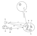
- FIG. 1 is a schematic diagram for explaining various lights acquired by a camera included in a vehicle.
- ADAS Advanced Driver-Assistance Systems
- image recognition used for automatic driving are recognized by AI or machine learning based on an image acquired by a camera 12 included in a vehicle 10.
- the light incident on the camera 12 includes the reflected light L1'from the traffic participant irradiated with the natural environment light L1 such as the light of the sun and the moon.
- the traffic participant 14 is a recognition target required for ADAS and automatic driving by a vehicle, and refers to an automobile, a bicycle, a motorcycle, a pedestrian, a traffic sign, a signal light, and the like.
- the illumination light L2 from the lighting fixtures provided in the automobile 16 and the motorcycle 18 and the lighting equipment such as a traffic light is also incident on the camera 12.
- the irradiation light L3 emitted from the lamp 20 as a light emitting portion included in the vehicle 10 to the surroundings of the vehicle irradiates the traffic participant 14, and the reflected light L3'is also incident on the camera 12.
- the light incident on the camera is various, and it is not easy to determine which light causes the bright part and the shadow in one image.
- the contrast generated by the ambient light L2 and the light L3 formed by the low beam cut line of the vehicle 10 can be raised.
- the natural ambient light L1 of the sun and the shadows created by the building reduce the recognition accuracy.
- the surroundings become dim and difficult to see, but even if the headlamp of the vehicle 10 irradiates the light, the effect is small and it is difficult to recognize.
- the way shadows are formed differs depending on how the light hits, so it is conceivable that AI and machine learning learning must be performed assuming those scenes as well.
- the inventors of the present application detect only the reflected light L3'by the light L3 emitted from the own vehicle side, so that the light L3'is not affected by the ambient light and is stable without shadows. I came up with the possibility of acquiring the image that was created. Specifically, the following method can be considered as a method of efficiently capturing only the reflection of the light on the own vehicle side without being affected by the external light.
- Method 1 Select the wavelength of the light to be irradiated. For example, light having a wavelength band relatively small among ambient light (near infrared rays of 940 nm ⁇ 20 nm) is used.
- Method 2 By shortening the exposure time of the camera and irradiating high-power light in a pulsed manner in synchronization with the exposure time, the light of the own vehicle is efficiently captured while suppressing the external light capture.
- the image 1 is acquired by exposing in synchronization with the irradiation of the light of the own vehicle at the first timing. Subsequently, at the second timing, the camera is exposed without irradiating the light of the own vehicle to acquire the image 2. After that, by generating a difference image between the image 1 and the image 2, the light other than the irradiation light of the own vehicle is canceled out.
- the influence of ambient light can be further reduced.
- the method 1 uses near infrared rays having a peak wavelength of about 940 nm, for example, the method 2 and the method 3 may be combined using visible light.
- the light source may be shared with the function of DRL (Daytime Running Lamps).
- the irradiation light of the vehicle is to average 10,000 cd / m 2 (for example, the output is an average 10 W).
- the irradiation light of the own vehicle is output at an average of 10 W with a duty of 1%, 1000 W can be output instantaneously, and the brightness becomes 1 million cd / m 2 .
- FIG. 2 is a block diagram of the imaging system 100 according to the present embodiment.
- the imaging system 100 includes a light emitting unit 102 that emits light to the surroundings of the vehicle, an imaging unit 104 that images a range including a region irradiated with the light emitted by the light emitting unit 102, and a light emitting unit 102. It has a control unit 106 that controls the intensity of emitted light, the light emission timing, the sensitivity of the imaging unit, and the imaging timing.
- the control unit 106 has a difference image generation unit 108 that generates a difference image from a plurality of captured images captured by the imaging unit 104.
- FIG. 3 is a schematic diagram showing an example of image processing by the imaging system according to the present embodiment.
- the captured image 1 includes information on the reflected light L1'caused by the natural environment light L1 shown in FIG. 1, the irradiation light L2 from the traffic participant 14, and the reflected light L3'of the light emitted by the lamp 20.
- the captured image 2 since the captured image 2 is captured with the lamp 20 not lit, it does not include the information of the reflected light L3', but includes only the information of the reflected light L1'and the irradiation light L2. Therefore, the difference image generation unit 108 of the control unit 106 generates the difference image 1 from the captured image 1 and the captured image 2.
- the difference image 1 containing only the reflected light L3'information is obtained from the captured image 1 and the captured image 2, and only the reflected light L3'information is included from the captured image 3 and the captured image 4.
- the difference image 2 is obtained.
- the number of difference images that can be obtained is two for a four-frame captured image, and if it is attempted to acquire four difference images in the same time, it is necessary to double the frame rate.
- the information contained in the difference image 1 and the difference image 2 includes the surroundings of the vehicle after the camera exposure and lamp irradiation are completed in the frame F2 (T2 + t1) and before the timing T3 when the imaging is started in the frame F3. It does not include changes in the situation that occurred in. That is, information may be lost in some periods.
- FIG. 5 is a schematic diagram showing another example of image processing by the imaging system according to the present embodiment.
- the difference image generation unit 108 included in the imaging system 100 according to the present embodiment generates n-1 difference images from n (n is an integer of 3 or more) captured images.
- the difference image generation unit 108 generates a difference image based on the image captured when the light emitting unit is lit and the image captured when the light emitting unit is dimmed, which are included in the n images.
- n is an integer of 3 or more
- the captured image 1 and the captured image 3 are images captured with the lamp irradiation
- the captured image 2 and the captured image 4 are images captured without the lamp irradiation (or in a dimmed state).
- the imaging unit 104 acquires four captured images 1 to 4 from four consecutive frames. As a result, it becomes difficult to miss information on the change in the situation around the vehicle that occurs between the difference image and the difference image, as compared with the case where four captured images are acquired from four discontinuous frames.
- FIG. 6 is a schematic view showing a state in which a plurality of traffic signs having different distances are irradiated by a light emitting unit included in the vehicle.
- FIG. 7 is a schematic view showing a modified example of image processing by the imaging system according to the present embodiment.
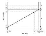
- FIG. 8 is a schematic diagram showing the relationship between the luminance value of the detection target and the gradation value after detection in the imaging unit according to the present embodiment.
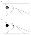
- 9 (a) is a diagram showing the captured image 1
- FIG. 9 (b) is a diagram showing the captured image 2.
- the traffic signs 22a and 22b shown in FIG. 6 have different distances from the vehicle 10, and the brightness values detected by the control unit 106 when the reflected light L3'is incident on the camera 12 are different.
- the camera continuously images the surroundings of the vehicle at a predetermined frame rate. Specifically, at the timing T1 of the frame F1, the exposure of the camera (time t1) is started, and the irradiation of the lamp (time t1' ⁇ time t1) is started at the luminous intensity C1. As a result, the first captured image 1 is obtained.
- the traffic sign 22a having the brightness value La'acquired by the camera 12 at the timing when the lamp is irradiated with the luminous intensity C2 is recognized as the traffic sign 22a having the gradation Ga'in the captured image 2.
- the traffic sign 22b having the brightness value Lb'acquired by the camera 12 at the timing when the lamp is irradiated with the luminous intensity C2 is recognized as the traffic sign 22b having the gradation Gb'in the captured image 2.
- FIGS. 9 (a) and 9 (b) show.
- the contents of the traffic signs 22a and 22b can be discriminated in any of the captured images.
- the difference image 1 including only the information of the reflected light L3'is obtained, and the natural environment.
- the influence of the reflected light L1'caused by the light L1 and the irradiation light L2 from the other traffic participants 14 can be suppressed.
- ADAS Advanced Driver-Assistance Systems
- automatic driving the accuracy of situation recognition using captured images and difference images is improved.
- FIG. 10 is a schematic diagram showing the relationship between the luminance value of the detection target and the gradation value after detection in the imaging unit in another situation of the present embodiment.
- FIG. 11 is a schematic view showing another modification of image processing by the imaging system according to the present embodiment.
- FIG. 12A is a diagram showing an image captured image 1 acquired by the camera 12 at the timing when the lamp is irradiated at the luminous intensity C1
- FIG. 12B is a diagram acquired by the camera 12 at the timing when the lamp is irradiated at the luminous intensity C2.
- FIG. 12C is a diagram showing the captured image 2 acquired by the camera 12 at the timing when the lamp is irradiated at the luminous intensity C3.
- the luminous intensity of the light emitting part may be too high depending on the distance between the vehicle and the traffic sign.
- the relationship between the luminance value of the detection target in the imaging unit and the gradation value after detection is included in the overexposure range R2 shown in FIG. Therefore, the traffic sign 22a having the brightness value La acquired by the camera 12 at the timing when the lamp is irradiated with the luminous intensity C1 becomes the gradation Ga (gradation value 255) in the captured image 1 and is recognized as pure white.
- the traffic sign 22b having the brightness value Lb acquired by the camera 12 at the timing when the lamp is irradiated with the luminous intensity C1 becomes the gradation Gb (gradation value 255) in the captured image 1 and is recognized as pure white (FIG. 12 (FIG. 12). a) See).
- the traffic sign 22a having the brightness value La'acquired by the camera 12 at the timing when the lamp is irradiated with the luminous intensity C2 becomes the gradation Ga'in the captured image 2, and the content of the sign is recognized.
- FIG. 13 (a) is a diagram showing the difference image 1
- FIG. 13 (b) is a diagram showing the difference image 2.
- the difference image generation unit 108 of the control unit 106 generates the difference image 1 from the captured image 1 and the captured image 2, and generates the difference image 2 from the captured image 1 and the captured image 2.
- the traffic sign 22b which could not be discriminated only by the captured image 1 and the captured image 2, can be discriminated by using the captured image 3.
- the accuracy of situation recognition using captured images and difference images is improved.
- the combination of the two captured images used when generating the difference image is not necessarily limited to the above-mentioned combination.
- the difference image 2 may be generated from the captured image 2 and the captured image 3.
- the imaging system 100 includes a difference image generation unit 108 that generates n-1 difference images from n images captured by the imaging unit 104.
- the difference image generation unit 108 includes the captured image 1 included in the n captured images when the light emitting unit 102 emits light at the luminous intensity C1, and the light emitting unit 102 at the luminous intensity C2 (0 ⁇ C2 ⁇ C1).
- the difference image 1 is generated based on the captured image 2 captured while the light is being emitted.
- a difference image is generated based on at least two captured images captured under irradiation conditions in which the luminous intensity of the light emitting unit 102 is different. Therefore, it becomes easy to obtain a difference image including an object having a discriminable brightness while reducing the influence of ambient light.
- the difference image generation unit 108 generates the difference image 2 based on the captured image 1 and the captured image 3 captured when the light emitting unit 102 emits light at a light intensity C3 (C2 ⁇ C3 ⁇ C1). do.
- C3 C2 ⁇ C3 ⁇ C1
- two difference images having different luminosity differences (C1-C2, C1-C3) of the light emitting portion when the two captured images are captured are generated. Therefore, there is a high possibility that at least one of the difference images includes an object having recognizable brightness.
- the imaging system 100 further includes a discriminating unit 110 that discriminates a plurality of traffic signs around the vehicle. As shown in FIG. 13A, the discrimination unit 110 can discriminate the traffic signs 22a included in the plurality of traffic signs from the difference image 1 and discriminate the traffic signs 22b included in the plurality of signs from the difference image 2. This increases the number of distinguishable signs.
- the discrimination unit 110 discriminates the traffic sign 22a located closer to the vehicle 10 than the traffic sign 22b from the difference image 1, and the traffic sign 22b located farther from the vehicle 10 than the traffic sign 22a from the difference image 2. Can be determined. As a result, even if there are a plurality of signs having different distances, both signs can be discriminated.
- the difference image generation unit 108 included in the imaging system 100 obtains n-1 difference images from n (n is an integer of 3 or more) captured images. Generate.
- the difference image generation unit 108 generates a difference image based on the image captured when the light emitting unit is lit and the image captured when the light emitting unit is dimmed, which are included in the n images.
- n is an integer of 3 or more
- the difference image generation unit 108 generates a difference image based on the image captured when the light emitting unit is lit and the image captured when the light emitting unit is dimmed, which are included in the n images.
- three differential images are generated from four captured images will be described.
- the captured image 1 and the captured image 3 are images captured with the lamp irradiation
- the captured image 2 and the captured image 4 are images captured without the lamp irradiation (or in a dimmed state).
- the difference image 1 containing only the information of the reflected light L3'is obtained from the captured image 1 and the captured image 2, and the information of the reflected light L3'from the captured image 2 and the captured image 3 is obtained.
- the imaging unit 104 acquires four captured images 1 to 4 from four consecutive frames. As a result, it becomes difficult to miss information on the change in the situation around the vehicle that occurs between the difference image and the difference image, as compared with the case where four captured images are acquired from four discontinuous frames.
- the difference image generation unit 108 dims the light emitting unit 102 acquired from the captured image 1 acquired from the frame F1 when the light emitting unit 102 is lit and the frame F2 following the frame F1.
- the difference image 1 is generated from the captured image 2 captured at the time, and the difference image 2 is obtained from the captured image 3 captured when the light emitting unit 102 is lit, which is acquired from the frame F3 following the frame F2, and the above-mentioned captured image 2. Is being generated.
- two difference images 1 and 2 are generated from the three consecutive captured images 1 to 3.
- the difference image 1 and the difference image 2 are the differences between the captured images captured when the light emitting unit 102 is turned on and when the light emitting unit 102 is dimmed (including when the light emitting unit 102 is turned off), the light from the surrounding environment The influence of is suppressed. That is, since the region irradiated with the light emitted by the light emitting unit 102 is mainly imaged, the influence of the light from the surrounding environment and the shadow accompanying it is reduced, and the image recognition using the difference image generated from the captured image is performed. Increased accuracy.
- the light emitting unit 102 may be configured to emit light at a luminous intensity of 10 times or more the normal luminous intensity of the light source included in the vehicle lighting equipment of the vehicle 10.
- the light source included in the vehicle lighting equipment is, for example, an LED light source or a laser light source included in a head lamp or a daytime running lamp.
- the normal luminous intensity of the light source is, for example, the average luminous intensity of the light distribution pattern formed by the vehicle headlights included in the vehicle 10, and is in the range of several thousand to several tens of thousands (1,000 to 90,000) [cd]. be.
- the light emitting unit 102 is configured so that the instantaneous peak luminous intensity becomes tens of thousands to one million [cd] or more when it is turned on at the timing of imaging. As a result, the influence of light from the surrounding environment is further suppressed.
- the present invention has been described above with reference to the above-described embodiments, the present invention is not limited to the above-described embodiments, and the present invention is not limited to the above-described embodiments, and the configurations of the respective embodiments are appropriately combined or replaced. Is also included in the present invention. Further, it is also possible to appropriately rearrange the combinations and the order of processing in each embodiment based on the knowledge of those skilled in the art, and to add modifications such as various design changes to the embodiments. Additional embodiments may also be included within the scope of the invention.
- the present invention can be used in a vehicle imaging system.
Landscapes
- Engineering & Computer Science (AREA)
- Multimedia (AREA)
- Physics & Mathematics (AREA)
- General Physics & Mathematics (AREA)
- Signal Processing (AREA)
- Theoretical Computer Science (AREA)
- Mechanical Engineering (AREA)
- Computer Vision & Pattern Recognition (AREA)
- Traffic Control Systems (AREA)
- Studio Devices (AREA)
- Camera Bodies And Camera Details Or Accessories (AREA)
- Lighting Device Outwards From Vehicle And Optical Signal (AREA)
- Image Analysis (AREA)
Priority Applications (3)
| Application Number | Priority Date | Filing Date | Title |
|---|---|---|---|
| CN202180023448.3A CN115349251B (zh) | 2020-03-23 | 2021-03-19 | 摄像系统 |
| JP2022510420A JP7497423B2 (ja) | 2020-03-23 | 2021-03-19 | 撮像システム |
| US17/945,413 US12167141B2 (en) | 2020-03-23 | 2022-09-15 | Imaging system including difference image generator that generates difference images |
Applications Claiming Priority (4)
| Application Number | Priority Date | Filing Date | Title |
|---|---|---|---|
| JP2020051232 | 2020-03-23 | ||
| JP2020-051232 | 2020-03-23 | ||
| JP2020058081 | 2020-03-27 | ||
| JP2020-058081 | 2020-03-27 |
Related Child Applications (1)
| Application Number | Title | Priority Date | Filing Date |
|---|---|---|---|
| US17/945,413 Continuation US12167141B2 (en) | 2020-03-23 | 2022-09-15 | Imaging system including difference image generator that generates difference images |
Publications (1)
| Publication Number | Publication Date |
|---|---|
| WO2021193426A1 true WO2021193426A1 (ja) | 2021-09-30 |
Family
ID=77892554
Family Applications (1)
| Application Number | Title | Priority Date | Filing Date |
|---|---|---|---|
| PCT/JP2021/011356 Ceased WO2021193426A1 (ja) | 2020-03-23 | 2021-03-19 | 撮像システム |
Country Status (4)
| Country | Link |
|---|---|
| US (1) | US12167141B2 (https=) |
| JP (1) | JP7497423B2 (https=) |
| CN (1) | CN115349251B (https=) |
| WO (1) | WO2021193426A1 (https=) |
Cited By (1)
| Publication number | Priority date | Publication date | Assignee | Title |
|---|---|---|---|---|
| JPWO2023067670A1 (https=) * | 2021-10-19 | 2023-04-27 |
Families Citing this family (3)
| Publication number | Priority date | Publication date | Assignee | Title |
|---|---|---|---|---|
| WO2022012748A1 (en) * | 2020-07-15 | 2022-01-20 | Veoneer Sweden Ab | Vision system for a motor vehicle |
| DE102020007061B4 (de) * | 2020-11-19 | 2022-08-11 | Daimler Truck AG | Verfahren zum Betreiben einer ersten Beleuchtungseinrichtung, einer zweiten Beleuchtungseinrichtung und eines optischen Sensors, Steuereinrichtung zur Durchführung eines solchen Verfahrens, Gated-Kamera-Vorrichtung mit einer solchen Steuereinrichtung und Kraftfahrzeug mit einer solchen Gated-Kamera-Vorrichtung |
| US20250047984A1 (en) * | 2023-07-31 | 2025-02-06 | Zebra Technologies Corporation | Technologies for Improving Imaging System Wakeup and Indicia Decoding |
Citations (2)
| Publication number | Priority date | Publication date | Assignee | Title |
|---|---|---|---|---|
| JP2002230563A (ja) * | 2001-02-05 | 2002-08-16 | Nissan Motor Co Ltd | 車両用カメラの映り込み検出方法および画像処理装置 |
| JP2003087644A (ja) * | 2001-09-07 | 2003-03-20 | Matsushita Electric Ind Co Ltd | 撮像表示装置、撮像表示方法及びプログラム |
Family Cites Families (7)
| Publication number | Priority date | Publication date | Assignee | Title |
|---|---|---|---|---|
| JP2010050535A (ja) * | 2008-08-19 | 2010-03-04 | Toyota Motor Corp | 撮像装置 |
| JP5161751B2 (ja) * | 2008-12-19 | 2013-03-13 | パナソニック株式会社 | 撮像装置並びに撮像システム |
| JP5251680B2 (ja) | 2009-03-31 | 2013-07-31 | 株式会社豊田中央研究所 | 照明制御装置及びプログラム |
| JP5573209B2 (ja) * | 2010-02-04 | 2014-08-20 | ソニー株式会社 | 画像処理装置、画像処理方法、プログラム、及び電子機器 |
| JP5469527B2 (ja) | 2010-05-10 | 2014-04-16 | パナソニック株式会社 | 撮像装置 |
| CN110087946B (zh) * | 2016-12-15 | 2023-01-10 | 株式会社小糸制作所 | 车辆用照明系统和车辆 |
| JP6780543B2 (ja) * | 2017-02-28 | 2020-11-04 | 沖電気工業株式会社 | 画像撮像システム及び画像撮像装置 |
-
2021
- 2021-03-19 CN CN202180023448.3A patent/CN115349251B/zh active Active
- 2021-03-19 WO PCT/JP2021/011356 patent/WO2021193426A1/ja not_active Ceased
- 2021-03-19 JP JP2022510420A patent/JP7497423B2/ja active Active
-
2022
- 2022-09-15 US US17/945,413 patent/US12167141B2/en active Active
Patent Citations (2)
| Publication number | Priority date | Publication date | Assignee | Title |
|---|---|---|---|---|
| JP2002230563A (ja) * | 2001-02-05 | 2002-08-16 | Nissan Motor Co Ltd | 車両用カメラの映り込み検出方法および画像処理装置 |
| JP2003087644A (ja) * | 2001-09-07 | 2003-03-20 | Matsushita Electric Ind Co Ltd | 撮像表示装置、撮像表示方法及びプログラム |
Cited By (2)
| Publication number | Priority date | Publication date | Assignee | Title |
|---|---|---|---|---|
| JPWO2023067670A1 (https=) * | 2021-10-19 | 2023-04-27 | ||
| JP7475556B2 (ja) | 2021-10-19 | 2024-04-26 | 三菱電機株式会社 | 車両用点灯制御装置、及び車両用点灯制御方法 |
Also Published As
| Publication number | Publication date |
|---|---|
| US20230017893A1 (en) | 2023-01-19 |
| US12167141B2 (en) | 2024-12-10 |
| JP7497423B2 (ja) | 2024-06-10 |
| JPWO2021193426A1 (https=) | 2021-09-30 |
| CN115349251B (zh) | 2024-05-10 |
| CN115349251A (zh) | 2022-11-15 |
Similar Documents
| Publication | Publication Date | Title |
|---|---|---|
| JP7497423B2 (ja) | 撮像システム | |
| JP4108631B2 (ja) | 車両のヘッドライトを自動的に減光する制御システム | |
| US7358496B2 (en) | Infrared night vision system, in colour | |
| JP7497372B2 (ja) | 車両用灯具システム、配光制御装置および配光制御方法 | |
| US20120127313A1 (en) | Method and device for a vehicle-based illumination in insufficiently illuminated traffic environments | |
| US11066006B2 (en) | Vehicle lamp | |
| JP5251680B2 (ja) | 照明制御装置及びプログラム | |
| JP2016096417A (ja) | 車載カメラシステム | |
| JP2007076429A (ja) | ヘッドランプシステム | |
| JP2017193239A (ja) | 車載システム | |
| JP7136055B2 (ja) | 露光制御装置 | |
| KR102184335B1 (ko) | 고명암비 이미지의 생성 방법 및 장치 | |
| WO2018173715A1 (ja) | 照明撮像装置 | |
| US12495215B2 (en) | Device and method for synchronizing a headlamp of a motor vehicle using a camera | |
| CN116601051B (zh) | 用于运行至少一个车辆前照灯的方法和车辆 | |
| TWI751717B (zh) | 提升影像辨識率的前處理方法及系統 | |
| US11657526B2 (en) | Distance measurement device | |
| CN113844357A (zh) | 识别机动车周围环境中对象的方法、设备、计算机程序和存储介质 | |
| RU130728U1 (ru) | Устройство распознавания автомобильных регистрационных знаков | |
| JP2021044667A (ja) | 露光制御装置 | |
| JP6944310B2 (ja) | 特定対象物検出装置 | |
| CN109963084A (zh) | 行人检测红外摄像照明装置 | |
| JP2018047863A (ja) | 車両用前照灯制御装置 | |
| JP2014235079A (ja) | 付着物検出装置、移動体機器制御システム及び移動体 | |
| JP2023055317A (ja) | 撮像システム、撮像方法 |
Legal Events
| Date | Code | Title | Description |
|---|---|---|---|
| 121 | Ep: the epo has been informed by wipo that ep was designated in this application |
Ref document number: 21775896 Country of ref document: EP Kind code of ref document: A1 |
|
| ENP | Entry into the national phase |
Ref document number: 2022510420 Country of ref document: JP Kind code of ref document: A |
|
| NENP | Non-entry into the national phase |
Ref country code: DE |
|
| 122 | Ep: pct application non-entry in european phase |
Ref document number: 21775896 Country of ref document: EP Kind code of ref document: A1 |