WO2021193374A1 - 通信装置および通信システム - Google Patents
通信装置および通信システム Download PDFInfo
- Publication number
- WO2021193374A1 WO2021193374A1 PCT/JP2021/011204 JP2021011204W WO2021193374A1 WO 2021193374 A1 WO2021193374 A1 WO 2021193374A1 JP 2021011204 W JP2021011204 W JP 2021011204W WO 2021193374 A1 WO2021193374 A1 WO 2021193374A1
- Authority
- WO
- WIPO (PCT)
- Prior art keywords
- retransmission
- data
- area
- transmitted
- unit
- Prior art date
- Legal status (The legal status is an assumption and is not a legal conclusion. Google has not performed a legal analysis and makes no representation as to the accuracy of the status listed.)
- Ceased
Links
Images








Classifications
-
- H—ELECTRICITY
- H04—ELECTRIC COMMUNICATION TECHNIQUE
- H04L—TRANSMISSION OF DIGITAL INFORMATION, e.g. TELEGRAPHIC COMMUNICATION
- H04L1/00—Arrangements for detecting or preventing errors in the information received
- H04L1/12—Arrangements for detecting or preventing errors in the information received by using return channel
- H04L1/16—Arrangements for detecting or preventing errors in the information received by using return channel in which the return channel carries supervisory signals, e.g. repetition request signals
- H04L1/18—Automatic repetition systems, e.g. Van Duuren systems
- H04L1/1867—Arrangements specially adapted for the transmitter end
- H04L1/1887—Scheduling and prioritising arrangements
-
- H—ELECTRICITY
- H04—ELECTRIC COMMUNICATION TECHNIQUE
- H04L—TRANSMISSION OF DIGITAL INFORMATION, e.g. TELEGRAPHIC COMMUNICATION
- H04L1/00—Arrangements for detecting or preventing errors in the information received
- H04L1/12—Arrangements for detecting or preventing errors in the information received by using return channel
- H04L1/16—Arrangements for detecting or preventing errors in the information received by using return channel in which the return channel carries supervisory signals, e.g. repetition request signals
- H04L1/18—Automatic repetition systems, e.g. Van Duuren systems
- H04L1/1825—Adaptation of specific ARQ protocol parameters according to transmission conditions
-
- H—ELECTRICITY
- H04—ELECTRIC COMMUNICATION TECHNIQUE
- H04L—TRANSMISSION OF DIGITAL INFORMATION, e.g. TELEGRAPHIC COMMUNICATION
- H04L1/00—Arrangements for detecting or preventing errors in the information received
- H04L1/12—Arrangements for detecting or preventing errors in the information received by using return channel
- H04L1/16—Arrangements for detecting or preventing errors in the information received by using return channel in which the return channel carries supervisory signals, e.g. repetition request signals
- H04L1/18—Automatic repetition systems, e.g. Van Duuren systems
- H04L1/1829—Arrangements specially adapted for the receiver end
- H04L1/1854—Scheduling and prioritising arrangements
-
- H—ELECTRICITY
- H04—ELECTRIC COMMUNICATION TECHNIQUE
- H04L—TRANSMISSION OF DIGITAL INFORMATION, e.g. TELEGRAPHIC COMMUNICATION
- H04L1/00—Arrangements for detecting or preventing errors in the information received
- H04L1/12—Arrangements for detecting or preventing errors in the information received by using return channel
- H04L1/16—Arrangements for detecting or preventing errors in the information received by using return channel in which the return channel carries supervisory signals, e.g. repetition request signals
- H04L1/18—Automatic repetition systems, e.g. Van Duuren systems
- H04L1/1867—Arrangements specially adapted for the transmitter end
- H04L1/1874—Buffer management
-
- H—ELECTRICITY
- H04—ELECTRIC COMMUNICATION TECHNIQUE
- H04L—TRANSMISSION OF DIGITAL INFORMATION, e.g. TELEGRAPHIC COMMUNICATION
- H04L1/00—Arrangements for detecting or preventing errors in the information received
- H04L1/12—Arrangements for detecting or preventing errors in the information received by using return channel
- H04L1/16—Arrangements for detecting or preventing errors in the information received by using return channel in which the return channel carries supervisory signals, e.g. repetition request signals
- H04L1/18—Automatic repetition systems, e.g. Van Duuren systems
- H04L1/1867—Arrangements specially adapted for the transmitter end
- H04L1/189—Transmission or retransmission of more than one copy of a message
Definitions
- This disclosure relates to communication devices and communication systems.
- CMOS Complementary Metal Oxide Semiconductor
- TOF Time of Flight
- Patent Document 1 proposes a system capable of reducing the number of data buses when connecting a processing device and a plurality of image sensors by using the CIS-2 standard.
- the retransmitting may occur beyond the transmission start timing of the next frame. In that case, there is a concern that the delay spreads after the next frame and the desired frame rate cannot be maintained. Therefore, it is desirable to provide a communication device and a communication system capable of maintaining a desired frame rate.
- the communication device includes a determination unit that determines whether or not a retransmission request is possible based on a priority defined for each area in the frame in retransmission control, and a case where the determination unit allows a retransmission request. Is provided with a transmission unit that generates retransmission request data and transmits it to another communication device.
- the retransmission control in the retransmission control, whether or not the retransmission request is possible is determined based on the priority defined for each area in the frame, and if the retransmission request is possible, the retransmission request data. Is generated and sent to other communication devices. As a result, it is possible to prevent the delay from spreading after the next frame.
- the communication device includes a receiving unit that receives retransmission request data, a transmitting unit that transmits data to another communication device, and data transmitted from the transmitting unit. It is provided with a holding unit that holds the data as, and a control unit that controls retransmission of transmitted data based on the retransmission request data.
- the retransmission control when the retransmission request data is received, the retransmission control of the transmitted data held in the holding unit is performed based on the retransmission request data. As a result, it is possible to prevent the delay from spreading after the next frame.
- the communication device includes a determination unit that determines whether or not the transmitted packet can be retransmitted based on the priority defined for each area in the frame, and the determination unit that has already transmitted the packet.
- the packet includes a transmission unit that transmits the transmitted packet to another communication device.
- whether or not the transmitted packet can be retransmitted is determined based on the priority defined for each area in the frame, and whether or not the transmitted packet can be retransmitted is determined. In that case, the transmitted packet is transmitted to another communication device. As a result, it is possible to prevent the delay from spreading after the next frame.
- the communication system includes a transmitting device and a receiving device, and communicates between the transmitting device and the receiving device.
- the receiving device in the retransmission control, has a determination unit that determines whether or not a retransmission request can be made based on a priority defined for each area in the frame, and a retransmission request if the determination unit can make a retransmission request. It has a first transmission unit that generates request data and transmits it to a transmission device.
- the transmitting device includes a receiving unit that receives retransmission request data, a second transmitting unit that transmits data to the receiving device, and a holding unit that holds the data transmitted from the second transmitting unit as transmitted data. It also has a control unit that controls retransmission of transmitted data based on retransmission request data.
- whether or not the retransmission request is possible is determined based on the priority defined for each area in the frame, and if the retransmission request is possible, the retransmission request data. Is generated and transmitted from the transmitting device to the receiving device. As a result, it is possible to prevent the delay from spreading after the next frame.
- the communication system includes a transmitting device and a receiving device, and communicates between the transmitting device and the receiving device.
- the receiving device has a first transmitting unit that generates retransmission request data and transmits it to the transmitting device in retransmission control.
- the transmitting device includes a receiving unit that receives retransmission request data, a second transmitting unit that transmits data to the receiving device, and a holding unit that holds the data transmitted from the second transmitting unit as transmitted data.
- It has a determination unit for determining whether or not the transmitted data can be resent based on the retransmission request data and the priority defined for each area in the frame.
- the second transmitting unit transmits the transmitted packet to the receiving device when the determination unit can retransmit the transmitted packet.
- whether or not the transmitted packet can be retransmitted is determined based on the priority defined for each area in the frame, and whether or not the transmitted packet can be retransmitted is determined.
- the transmitted packet is transmitted from the transmitting device to the receiving device. As a result, it is possible to prevent the delay from spreading after the next frame.
- FIG. 5 is a diagram showing an example of a frame format and a packet format used in communication according to the A-PHY standard in the communication system of FIG. 1. It is a figure which shows an example of the functional block of the communication device in a sensor device and a control device. It is a figure which shows an example of the retransmission procedure when an error occurs in the communication system of FIG. It is a figure which shows an example of the retransmission procedure when an error occurs in the communication system of FIG. It is a figure which shows an example of the retransmission procedure when an error occurs in the communication system of FIG. It is a figure which shows an example of the retransmission procedure when an error occurs in the communication system of FIG.
- FIG. 1 It is a figure which shows an example of the retransmission control in the communication system of FIG. It is a figure which shows one modification of the functional block of the retransmission controller of FIG. It is a figure which shows one modification of the functional block of the transmitted buffer of FIG. It is a figure which shows an example of the schematic structure of the imaging system. It is a block diagram which shows an example of the schematic structure of a vehicle control system. It is explanatory drawing which shows an example of the installation position of the vehicle exterior information detection unit and the image pickup unit.
- FIG. 1 shows a schematic configuration example of the communication system 1 according to the embodiment of the present disclosure.
- the communication system 1 is mounted on a vehicle such as an automobile and includes a sensor unit 10 and a control device 20.
- the sensor unit 10 and the control device 20 are connected to each other via the bus 30.
- A-PHY which is a physical layer standard developed by the MIPI (Mobile Industry Processor Interface) Alliance, is used for signal transmission between the sensor unit 10 and the control device 20 via the bus 30.
- A-PHY is expected to correspond to a maximum transmission distance of 15 m, for example.
- the sensor device 10 includes, for example, an image sensor 11 (CIS) and a communication device 12.
- the image sensor 11 is connected to the communication device 12 via a bus according to the I3C standard.
- the control device 20 includes, for example, a communication device 21 and an application processor 22 (AP).
- the application processor 22 is connected to the communication device 21 via a bus according to the I3C standard. Communication according to the A-PHY standard is performed between the communication device 12 and the communication device 21 via the bus 30.
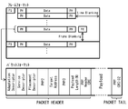
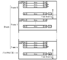
- FIG. 2 shows an example of a frame format and a packet format used in communication according to the A-PHY standard in the communication system 1.
- an image line is formed between the frame start (FS: Frame Start) indicating the start of the frame and the frame end (FE: Frame End) indicating the end of the frame.
- a packet containing the data of the line is generated for each, or a packet containing the data is generated for each data obtained by dividing the line into a plurality of parts.
- a plurality of pixels included in the image are included between the frame start (FS) indicating the start of the frame and the frame end (FE) indicating the end of the frame. Each time, a packet in which the data of the plurality of pixels is stored is generated.
- Packet tails include, for example, PHY CRC-32.
- Packet headers include, for example, Adaptation Descriptor, Service Descriptor, Placement Descriptor, PHY2, Target Addless, PHY3, Payload Lens and PHY Header CRC.
- the Adaptation Descriptor includes, for example, the Adaptation Type Value.
- the Adaptation Type Value for example, I 2 C, I3C, such as GPIO like.
- the packet header includes, for example, a message count (MC: Message Count) for identifying the packet.
- MC Message Count
- the packet header contains various information necessary for applying the communication system 1 to a vehicle such as an automobile. The communication system 1 realizes retransmission for each packet by individually identifying the packets by using the message count included in the packet header.
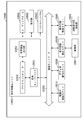
- FIG. 3 shows an example of the functional blocks of the communication devices 12 and 21.
- the communication system 1 transmits and receives control data between the communication device 12 and the communication device 21 via a low-speed and bidirectional control channel, for example. Further, the communication system 1 transmits sensor data such as an image from the communication device 12 to the communication device 21 via a high-speed and unidirectional data channel.
- the communication device 12 for example, includes a transmitter 51, a receiver 52, an error detection code calculator 53, an error detector 54, a control data classifier 55, a transmitted buffer 56, a transmission scheduler 57, an error detection code calculator 58, and a transmitter 59.
- a transmitter 51 for example, includes a transmitter 51, a receiver 52, an error detection code calculator 53, an error detector 54, a control data classifier 55, a transmitted buffer 56, a transmission scheduler 57, an error detection code calculator 58, and a transmitter 59.
- Each block arranged above the broken line shown in the communication device 12 is used for a process of transmitting and receiving control data, and each block arranged below the broken line is used for a process of transmitting sensor data. Used.
- the communication device 21 includes, for example, a transmitter 61, a receiver 62, an error detection code calculator 63, an error detector 64, a transmission / reception scheduler 65, a receiver 66, an error detector 67, a retransmission detector 68, and a retransmission controller 69.
- Each block arranged above the broken line shown in the communication device 21 is used for a process of transmitting and receiving control data, and each block arranged below the broken line is used for a process of receiving sensor data. Used.
- the transmitter 51 transmits the control data supplied from the error detection code calculator 53 to the communication device 21 via the control channel.
- the receiver 52 receives the control data transmitted from the communication device 21 via the control channel and supplies the control data to the error detector 54.
- the error detection code calculator 53 calculates, for example, a parity bit, a CRC (Cyclic Redundancy Check), or the like as an error detection code for the control data supplied via the control data classifier 55. Then, the error detection code calculator 53 adds the calculated code for error detection to the control data and supplies it to the transmitter 51.
- CRC Cyclic Redundancy Check
- the error detector 54 detects whether or not an error has occurred in the control data by using the error detection code added to the control data supplied from the receiver 52. Then, the error detector 54 supplies the control data to the control data classifier 55 as it is when no error occurs in the control data according to the result of performing the error detection of the control data. On the other hand, the error detector 54 notifies that an error has occurred in the control data and controls the control data when an error has occurred in the control data according to the result of performing the error detection of the control data. It is supplied to the data classifier 55.
- the control data classifier 55 inputs and outputs control data to and from a control circuit (not shown) that controls the image sensor 11, and identifies the control data transmitted from the communication device 21. That is, when the control data classifier 55 supplies the control data input from the control circuit to the error detection code calculator 53 and outputs the control data supplied from the error detector 54 to the control circuit, the control data To identify. For example, when the retransmission request data as described later is transmitted from the communication device 21 as the control data supplied from the error detector 54, the control data classifier 55 detects the retransmission request data and transmits the buffer. Supply to 56.
- a transmission packet transmitted from the communication device 12 to the communication device 21 is supplied to the transmission buffer 56 from the transmission scheduler 57. Then, the transmitted buffer 56 temporarily holds the transmitted packet (transmission data) supplied from the transmission scheduler 57 as a transmitted packet (transmitted transmission data). Further, when the retransmission request data is supplied from the control data classifier 55, the transmitted buffer 56 is appropriately retransmitted with the retransmission request data from the retained transmitted packets (transmitted transmission data). The transmitted packet (transmitted transmission data) is supplied to the transmission scheduler 57 as a retransmission packet (retransmission data).
- the sensor data stored in the payload of the transmission packet is also appropriately referred to as transmission data below.
- the sensor data stored in the payload of the retransmission packet is also appropriately referred to as retransmission data below.
- Sensor data is input to the transmission scheduler 57 from an image sensor (not shown) included in the image sensor 11.
- a packet in which sensor data newly input from the image sensor 11 to the transmission scheduler 57, that is, sensor data that is not retransmission data is stored in the payload is hereinafter appropriately referred to as a new packet.
- the transmission scheduler 57 exchanges a retransmission data transmission request and a retransmission data transmission permission with the transmission buffer 56 as described later, and the retransmission packet is supplied from the transmission buffer 56.
- the transmission scheduler 57 adjusts the timing of transmitting each of the new packet or the retransmission packet, and sequentially transmits the transmitted packet as the transmission packet from the communication device 12 to the communication device 21, the transmitted buffer 56 and the error detection code calculator. Supply to 58.
- the error detection code calculator 58 calculates, for example, a parity bit or CRC as a code for error detection of the transmission packet supplied from the transmission scheduler 57, adds the code for error detection to the packet, and transmits the transmitter 59. Supply to.
- the transmitter 59 transmits the transmission packet supplied from the error detection code calculator 58 to the communication device 21 via the data channel.
- the transmitter 61, the receiver 62, the error detection code calculator 63, and the error detector 64 are similarly configured as the transmitter 51, the receiver 52, the error detection code calculator 53, and the error detector 54, respectively.
- the transmission / reception scheduler 65 for example, inputs / outputs control data to / from a control circuit (not shown) that controls the application processor 22, and manages a schedule of control data to / from the communication device 12. .. That is, the transmission / reception scheduler 65 outputs the control data supplied from the error detector 64 to the control circuit, and supplies the control data input from the control circuit to the error detection code calculator 63 at a predetermined timing for communication. It is transmitted to the device 12. Further, when the retransmission request data is supplied from the retransmission controller 69, the transmission / reception scheduler 65 supplies the retransmission request data as control data to the error detection code calculator 63 and causes the communication device 12 to transmit the data.
- the receiver 66 receives the transmission packet transmitted from the communication device 12 via the data channel and supplies it to the error detector 67.
- the error detector 67 detects whether or not an error has occurred in the transmission packet by using the error detection code added to the transmission packet supplied from the receiver 66. Then, the error detector 67 detects whether or not an error has occurred in the transmission packet by using the error detection code added to the transmission packet, and the sensor data stored in the payload of the transmission packet. Is output to the processing circuit in the subsequent stage.
- the error detector 67 supplies an error detection result indicating the result of detecting an error occurring in the transmission packet to the retransmission detector 68. For example, when the error detector 67 detects that a header error or a payload error has occurred in the transmitted packet received by the communication device 21, it retransmits an error detection result indicating that the header error or the payload error has been detected. It is supplied to the detector 68. Further, the error detector 67 supplies the message count included in the additional packet header of the transmission packet received by the communication device 21 to the retransmission detector 68.
- the retransmission detector 68 detects the message count of the transmission packet that cannot be received by the communication device 21 and needs to be retransmitted based on the error detection result and the message count supplied from the error detector 67. Perform detection processing. Then, the retransmission detector 68 detects the message count detected in the retransmission detection process as a retransmission candidate message count that is a candidate for requesting retransmission, and supplies the message count to the retransmission controller 69.
- the retransmission detection process performed by the retransmission detector 68 will be described later.
- the retransmission controller 69 generates retransmission request data requesting transmission of the retransmission packet based on the retransmission candidate message count supplied from the retransmission detector 68 and various information transmitted from the communication device 12. Performs retransmission request processing to be supplied to the transmission / reception scheduler 65. The retransmission request processing performed by the retransmission detector 68 will be described later.
- the communication system 1 embeds various information necessary for performing the retransmission request processing in the retransmission controller 69 in the header of the transmission packet in which the sensor data is stored in the payload, and communicates from the communication device 12. It transmits to the device 21.
- the communication device 12 uses the user-defined area of the packet header defined by CSI-2 to transmit various information necessary for performing the retransmission request processing in the retransmission controller 69, and transmits various information thereof.
- Information is supplied to the retransmission controller 69 via the error detector 67.
- the communication device 12 and the communication device 21 have the above-described configuration, retransmission of each packet is realized by using the message count included in the packet header defined by A-PHY. That is, the communication device 12 and the communication device 21 perform retransmission control of MIPIA-PHY.
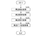
- FIG. 4 shows a flowchart of the packet retransmission process executed in the communication system 1.
- step S101 the retransmission detector 68 of the communication device 21 performs the retransmission detection process.
- the retransmission detector 68 detects the message count of the transmission packet that cannot be received by the communication device 21 and needs to be retransmitted based on the error detection result and the message count supplied from the error detector 67. do.
- step S102 the retransmission controller 69 of the communication device 21 performs the retransmission request processing.
- the retransmission controller 69 filters the retransmission candidate message count supplied from the retransmission detector 68 by the oldest message count held in the transmitted buffer 56, and requests the retransmission of the packet message. Create a retransmission list where the count is registered. As a result, a message count newer than the oldest message count held in the transmitted buffer 56 among the retransmission candidate message counts is registered in the retransmission list.
- the retransmission controller 69 determines whether or not the retransmission request is possible based on the priority defined for each area in the frame, and if the retransmission request is possible, generates the retransmission request data. Specifically, the retransmission controller 69 requests a retransmission based on the priority specified for each area in the frame, the number of retransmissions specified for each area, and the number of retransmissions counted for each area. Whether or not it is possible is determined, and if the retransmission request is possible, the retransmission request data is generated.
- step S103 the control data classifier 55 of the communication device 12 and the transmitted buffer 56 perform the retransmission acceptance process.
- the control data classifier 55 identifies the retransmission request data generated by the retransmission controller 69 from the control data supplied from the error detector 54, and supplies the retransmission request packet to the transmitted buffer 56. ..
- the transmitted buffer 56 searches for the retained transmitted packet using the message count specified in the retransmission request data, and when the transmitted packet for which retransmission is requested is acquired as a search result, the transmitted packet 56 is searched. Allocate the transmitted packet as a retransmission packet.
- the transmitted buffer 56 discards the retransmission request data used for the search.
- step S104 the transmission scheduler 57 of the communication device 12 performs the retransmission data transmission process.
- the transmission scheduler 57 adjusts the timing of transmitting the retransmission packet reserved in the transmission buffer 56 and the new packet in which the newly input sensor data is stored in the payload, and adjusts the timing of transmitting the new packet or the retransmission.
- the packet is appropriately transmitted as a transmission packet.
- the communication system 1 it is possible to request retransmission for each transmission packet transmitted from the communication device 12 to the communication device 21, and it is possible to execute transmission of the retransmission packet for which retransmission is requested.
- 5 and 6 show an example of retransmission detection processing when a payload error occurs in communication according to the A-PHY standard in the communication system 1.
- 5 and 6 are diagrams for explaining the retransmission detection process triggered by the reception of the message count included in the header, and the numbers (1 to 6) surrounded by the rectangular frame shown in FIG. 6) represents the message count.
- 5 and 6 show a state in which a payload error has occurred in the transmitted packets having message counts 2, 3 and 5.
- the communication device 21 When the communication device 21 receives the transmission packet having the message count 2, the communication device 21 confirms the header of the transmission packet to acquire the message count 2 included in the header. At this time, if a payload error has occurred in the transmitted packet, the communication device 21 performs a predetermined error detection process to recognize that the payload error has occurred in the transmitted packet having the message count 2.
- the communication device 21 determines whether or not the retransmission request is possible based on the priority defined for each area in the frame, and if the retransmission request is possible, generates the retransmission request data. Specifically, the communication device 21 allows or rejects a retransmission request based on the priority specified for each area in the frame, the number of retransmissions specified for each area, and the number of retransmissions counted for each area. If the retransmission request is possible, the retransmission request data is generated. The communication device 21 transmits the generated retransmission request data to the communication device 12.
- the communication device 12 When the communication device 12 receives the retransmission request data from the communication device 21, the communication device 12 secures the transmitted packet corresponding to the message count 2 specified in the received retransmission request data as the retransmission packet. The communication device 12 transmits the secured retransmission packet to the communication device 21 as a transmission packet at a predetermined timing. The same processing as described above is performed even when a payload error occurs in the transmitted packet having the message count 3 or the message count 5. Further, when a header error occurs in the transmitted packet, the same processing as described above is performed.
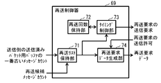
- FIG. 7 shows an example of a functional block of the retransmission controller 69.
- the retransmission controller 69 includes, for example, a retransmission list holding unit 71, a retransmission count holding unit 72, a timing control unit 73, and a retransmission request data generation unit 74.
- various information embedded in the header of the transmission packet and transmitted is supplied to the retransmission controller 69.
- this information includes information indicating the oldest message count of the transmitted packet buffer 84 (FIG. 10) of the transmitted buffer 56.
- the retransmission list holding unit 71 holds a retransmission list in which the message count of the packet requesting retransmission is registered, and manages the retransmission list. For example, the retransmission list holding unit 71 registers only the message count newer than the oldest message count held in the transmitted buffer 56 among the retransmission candidate message counts detected by the retransmission detector 68. Manage the resend list.
- the message count 100 is newly supplied as the oldest message count of the transmitted packet buffer 84 of the transmitted buffer 56. do.
- the retransmission list holding unit 71 deletes the message counts 98 and 99 older than the message count 100 from the retransmission list, so that only the message counts 100 to 102 newer than the message count 100 are registered in the retransmission list.
- the retransmission count holding unit 72 has a register (FIG. 9) in which data corresponding to the concept shown in FIG. 8 is stored.
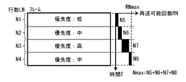
- FIG. 8 illustrates how the priority is set for each predetermined area in the frame (one image data).
- the frame (one image data) is prioritized for each predetermined number of lines from top to bottom. For example, the priority "low” is set for each line (first area) for N1 lines from the top, and each line for N2 lines (second area) from the line for which the priority "low” is set. ) Is set with a priority of "medium”, and each line (third area) for N3 lines from the line for which the priority is set with "medium” is set with a priority of "high”.
- the priority "medium” is set for each line (fourth area) for N4 lines from the line for which the priority "high” is set.
- the number of retransmittable times RN according to the priority is set to N5 for the first area, and the retransmission according to the priority is set for the second area.
- the possible number of times RN is set to N6, the retransmittable number of times RN according to the priority is set to N7 for the third area, and the retransmittable number of times RN according to the priority is set to N7 for the fourth area. It is set to N8.
- N5 + N6 + N7 + N8 is the number of retransmittable times Nmax per frame (one image data).
- the retransmittable number Nmax is set to the number of times that the logical layer can send a packet within a range not exceeding 97.5% of the effective transfer rate of the physical layer according to the A-PHY standard. Is preferable.
- various setting values such as the number of rows LN, the number of retransmittable times RN, the own area carry-over possibility flag CA, and the carry-over possibility flag M are defined for each area.
- the setting values for each area are recorded in the register in order. For example, the set value of the first area, the set value of the second area, the set value of the third area, and the set value of the fourth area are recorded in the register in this order.
- the number of rows LN is the number of pixel rows included in the corresponding area.
- the retransmittable number of times RN is an upper limit of the number of times that retransmitting can be requested in the corresponding area.
- the own area carry-over possibility flag CA subtracts RNA from RN when the number of retransmission requests (RNa) actually made in the corresponding area is less than the number of retransmittable times RN set in the register in the corresponding area. It is a flag for setting whether or not to add the value (RN-RNA) to the retransmittable number of times RN in the next area.
- the number of times (RNA) per area of the actual retransmission request is recorded in the register.
- RN-RNa When the own area carry-over possibility flag CA is "File", RN-RNa is not added to the retransmittable number of times RN in the next area. When the own area carry-over possibility flag CA is "Enable”, RN-RNa is added to the retransmittable number of times RN in the next area. When RN-RNa is added to the retransmittable number RN, the retransmittable number RN in the area is a number larger than the retransmittable number RN set in the register by RN-RNa.
- the carry-over possibility flag M sets the number of retransmittable times remaining unused (remaining number of times RNb) regardless of whether or not RN-RNa in the area before the own area is added to the retransmittable number RN of the own area. , Is a flag for setting whether or not to add to the retransmittable number of times RN in the next area.
- the carry-over enable / disable flag M is “File”, the remaining number of times RNb is not added to the number of times retransmittable RN in the next area.
- the carry-over possibility flag M is "Enable”, the remaining number of times RNb is added to the number of times retransmittable RN of the next area.
- the timing control unit 73 has sent packets (transmitted packets) corresponding to the message counts registered in the retransmission list of the retransmission list holding unit 71, based on the priority set for each area in the frame (one image data). Hereinafter, the control is performed to retransmit the “transmitted packet X”) as a retransmission packet. Specifically, the timing control unit 73 sets various types of registers in the area corresponding to the message count registered in the retransmission list of the retransmission list holding unit 71 (hereinafter, referred to as “area ⁇ ”).
- the timing control unit 73 requests transmission of a retransmission request, for example, when the number of retransmission requests (RNa) actually made in the area ⁇ does not exceed the number of retransmission requests RN set in the register for the area ⁇ .
- a transmission request for a retransmission request for retransmitting the transmitted packet X as a retransmission packet is made to the transmission / reception scheduler 65.
- the timing control unit 73 determines, for example, that the number of retransmission requests (RNa) actually made in the area ⁇ is the area ⁇ .
- the transmission request of the retransmission request is possible, and the transmitted packet X is retransmitted as a retransmission packet.
- a request for transmission of a request is made to the transmission / reception scheduler 65. Further, in the timing control unit 73, for example, the number of retransmission requests actually made in the frame (one image data) exceeds the number of retransmissions Nmax defined for the frame (one image data). If not, it is determined that the transmission request of the retransmission request is possible, and the transmission / reception scheduler 65 is requested to transmit the retransmission request to retransmit the transmitted packet X as the retransmission packet.
- the retransmission request data generation unit 74 corresponds to the message count read from the retransmission list of the retransmission list holding unit 71 when transmission permission is obtained from the transmission / reception scheduler 65 for the transmission request issued by the timing control unit 73. Generates retransmission request data requesting retransmission of the transmitted packet and supplies it to the transmission / reception scheduler 65.
- FIG. 10 shows an example of a functional block of the transmitted buffer 56.
- the transmitted buffer 56 includes, for example, a write control unit 81, a transfer control unit 82, a read control unit 83, a transmitted packet buffer 84, and a retransmission packet buffer 85.
- the write control unit 81 performs write control for writing the transmitted packet supplied from the transmission scheduler 57 to the transmitted packet buffer 84.
- the transfer control unit 82 searches the transmitted packets of the message count specified by the retransmission request data supplied from the control data classifier 55 from the transmitted packets held in the transmitted packet buffer 84. Then, when the transmitted packet of the message count specified in the retransmission request data can be acquired as the search result, the forwarding control unit 82 performs forwarding control to transfer the transmitted packet to the retransmission packet buffer 85. .. If the transfer control unit 82 cannot acquire the transmitted packet of the message count specified in the retransmission request data as the search result, the transfer control unit 82 discards the retransmission request data.
- the read control unit 83 manages the address of the retransmission packet held by the retransmission packet buffer 85, and requests the transmission scheduler 57 to transmit the retransmission packet held by the retransmission packet buffer 85. Issue a data transmission request. Then, when the retransmission data transmission permission is obtained from the transmission scheduler 57, the read control unit 83 performs read control to read the retransmission packet from the retransmission packet buffer 85 and supply it to the transmission scheduler 57.
- the transmitted packet buffer 84 holds the transmitted packet, and the retransmission packet buffer 85 holds the retransmission packet.
- FIG. 11 shows an example of a functional block of the transmission scheduler 57.
- the transmission scheduler 57 includes, for example, a sensor data buffer 91, a switching unit 92, and a control unit 93, as shown in FIG.
- the sensor data buffer 91 temporarily stores a new packet in which sensor data newly input from an image sensor (not shown) included in the image sensor 11 is stored in the payload.
- the sensor data buffer 91 is required because it is assumed that a new packet in which the sensor data is stored in the payload is input during the output of the retransmission packet supplied from the transmitted buffer 56.
- the switching unit 92 switches between the new packet stored in the sensor data buffer 91 and the retransmission packet supplied from the transmitted buffer 56 according to the control by the control unit 93, and outputs the new packet from the transmission scheduler 57.
- the control unit 93 acquires the retransmission data transmission request issued from the transmission buffer 56
- the control unit 93 controls the switching of the output by the switching unit 92.
- the control unit 93 acquires, for example, the retransmission data transmission request issued from the transmission buffer 56
- the control unit 93 switches the output by the switching unit 92 to the retransmission data side.
- whether or not the retransmission request is possible is determined based on the priority defined for each area in the frame, and if the retransmission request is possible, the retransmission request data is generated and other communication is performed. Sent to the device. As a result, it is possible to prevent the delay from spreading after the next frame. As a result, the desired frame rate can be maintained.
- the number of retransmissions according to the priority is defined for each area in the frame.
- whether or not the retransmission request is possible is determined based on the number of retransmissions specified for each area in the frame, and if the retransmission request is possible, the retransmission request data is generated and transmitted to another communication device.
- the retransmission request data is generated and transmitted to another communication device.
- the number of retransmission requests actually made in each area does not exceed the number of retransmission requests, it is determined that the retransmission request is possible. As a result, it is possible to prevent the delay from spreading after the next frame. As a result, the desired frame rate can be maintained.
- the area is set for each predetermined number of lines in the frame.
- an image sensor 11 is provided on a moving body such as an automobile, and image data can be obtained by imaging the front of the moving body with the image sensor 11.
- the hood of the automobile is reflected in the lower region of the image data
- the road in front of the automobile is reflected in the central region of the image data
- the sky in front of the automobile is reflected in the upper region of the image data. May be reflected.
- the desired frame rate is maintained by setting the area in the frame for each predetermined number of rows in the frame. At the same time, it is possible to secure the retransmission of a region of high importance in the image data.
- the priority is set for each predetermined number of lines from top to bottom.
- the priority may be set for each predetermined number of columns from left to right.
- a frame format for transmitting an image for one frame from the frame start (FS) indicating the start of the frame to the frame end (FE) indicating the end of the frame, for each image column, that column.
- FS frame start
- FE frame end
- a packet containing the above data is generated, or a packet containing the data is generated for each data obtained by dividing the column into a plurality of parts.
- the priority is set for each predetermined number of columns from the left.
- the priority "low” is set for each column (first area) for N1 columns from the left, and each column for N2 columns (second area) from the column for which the priority "low” is set.
- each column (third area) for N3 columns from the column with the priority "high” is set with a priority "medium”.
- the priority "low” is set for each column (fourth area) for N4 columns from the column in which the priority "medium” is set.
- the retransmittable number RN is set to N5 for the first area
- the retransmittable number RN is set to N6 for the second area
- the retransmittable number RN is set for the third area.
- the retransmittable number of times RN is set to N8 for the fourth area.
- N5 + N6 + N7 + N8 is the number of retransmittable times Nmax per frame (one image data).
- various setting values such as the number of columns CN, the number of resendable times RN, the own area carry-over possibility flag CA, and the carry-over possibility flag M are defined in the register for each area.
- the setting values for each area are recorded in the register in order.
- the set value of the first area, the set value of the second area, the set value of the third area, and the set value of the fourth area are recorded in the register in this order.
- the number of columns CN is the number of pixel strings included in the corresponding area.
- the area is set for each predetermined number of columns in the frame.
- an image sensor 11 is provided on a moving body such as an automobile, and image data can be obtained by imaging the left front of the moving body with the image sensor 11.
- the body and pillars of the automobile are reflected in the rightmost region in the image data
- the road in front of the left side of the automobile is reflected in the central region in the image data
- the road is shown in the leftmost region in the image data.
- the road shoulder and guardrail are reflected.
- the desired frame rate is maintained by setting the area in the frame for each predetermined number of columns in the frame. At the same time, it is possible to secure the retransmission of a region of high importance in the image data.
- the priority is set for each predetermined number of lines from top to bottom.
- the priority may be set for each predetermined plurality of pixels.
- a frame format for transmitting an image for one frame for each of a plurality of pixels included in the image between the frame start (FS) indicating the start of the frame and the frame end (FE) indicating the end of the frame.
- FS frame start
- FE frame end
- a packet in which the data of the plurality of pixels is stored is generated.
- the priority is set for each of a plurality of predetermined pixels. For example, for an inverted V-shaped area (first area), a priority "high” is set, and an area adjacent to the area (first area) in which the priority "high” is set (first area). For 2 areas), the priority “medium” is set, and for each area (3rd area) adjacent to the upper right and upper left of the area (1st area) for which the priority "high” is set. , Each area (4th area) adjacent to each area (3rd area) where the priority "low” is set and the priority "low” is set, and the area where the priority "medium” is set.
- the priority "extremely low” is set for the adjacent area (fourth area) under the (second area).
- the retransmittable count RN is set to N8 for the first area
- the retransmittable count RN is set to N7 for the second area
- the retransmittable count RN is set for the third area.
- the number of retransmittable times RN is set to N5 for the fourth area.
- N5 + N6 + N7 + N8 is the number of retransmittable times Nmax per frame (one image data).
- various setting values such as the retransmittable number of times RN, the own area carry-over possibility flag CA, and the carry-over possibility flag M are defined in the register for each area.
- the setting values for each area are recorded in the register in order.
- the set value of the first area, the set value of the second area, the set value of the third area, and the set value of the fourth area are recorded in the register in this order.
- the register further defines the coordinates for partitioning each area, for example, as shown in FIG.
- the area is set for each predetermined plurality of pixels in the frame.
- an image sensor 11 is provided on a moving body such as an automobile, and image data can be obtained by imaging the front of the moving body with the image sensor 11.
- the inverted V-shaped region in the image data shows a road extending straight and far in front of the automobile, and the region adjacent below the inverted V-shaped region in the image data is the automobile.
- the bonnet of the above is reflected, and there is a possibility that the road shoulder and the guardrail are reflected in the areas adjacent to the upper left and upper right of the inverted V-shaped area in the image data.
- the number of retransmission requests (RNA) actually made in the corresponding area is set in the register in the corresponding area.
- the retransmission controller 69 may transmit an error flag indicating that the RNA has exceeded the possible number of times RNA RN to the transmission / reception scheduler 65.
- the transmission / reception scheduler 65 supplies the error flag as control data to the error detection code calculator 63 and causes the communication device 12 to transmit the error flag.
- the control data classifier 55 supplies the error flag to the transmitted buffer 56.
- the transmitted buffer 56 acquires the error flag
- the transmitted buffer 56 stops supplying the retransmission packet to the transmission scheduler 57.
- the communication device 12 further adds an NG flag indicating that retransmission is not possible to the frame end.
- the retransmission count holding unit 72 may be provided in the transmission buffer 56 instead of the retransmission controller 69.
- the timing control unit 73 retransmits the transmitted packet (hereinafter, referred to as “transmitted packet X”) corresponding to the message count registered in the retransmission list of the retransmission list holding unit 71 as a retransmission packet. Control for. Specifically, the timing control unit 73 makes a transmission request for a retransmission request to retransmit the transmitted packet X as a retransmission packet to the transmission / reception scheduler 65.
- the transfer control unit 82 sends a transmitted packet having a message count specified in the retransmission request data supplied from the control data classifier 55 based on the priority set for each area in the frame (one image data). (Hereinafter referred to as "transmitted packet X") is controlled to be retransmitted as a retransmission packet. Specifically, the transfer control unit 82 sets the register for the area corresponding to the message count specified by the retransmission request data supplied from the control data classifier 55 (hereinafter, referred to as “area ⁇ ”). Based on the various settings made and the number of retransmission requests (RNA) actually made in the area ⁇ , it is determined whether or not to retransmit the transmitted packet X.
- area ⁇ the register for the area corresponding to the message count specified by the retransmission request data supplied from the control data classifier 55
- the transfer control unit 82 determines, for example, when the number of retransmission requests (RNa) actually made in the area ⁇ does not exceed the number of retransmissions RN set in the register for the area ⁇ , the transmitted packet X It is determined that retransmission is possible, and transfer control is performed to transfer the transmitted packet X to the retransmission packet buffer 85. However, when the carry-over enable / disable flag M for the area ⁇ is set to “Enable” in the register, the transfer control unit 82 determines, for example, that the number of retransmission requests (RNa) actually made in the area ⁇ is the area ⁇ .
- the transmitted packet X is set in the retransmission packet buffer 85. Transfer control is performed for transfer. Further, in the transfer control unit 82, for example, the number of retransmission requests actually made in the frame (one image data) exceeds the retransmission possible number Nmax set for the frame (one image data). If not, it is determined that the transmitted packet X can be retransmitted, and transfer control is performed to transfer the transmitted packet X to the retransmission packet buffer 85.
- the transfer control unit 82 searches the transmitted packet X from the transmitted packets held in the transmitted packet buffer 84. Then, when the transmitted packet X can be acquired as a search result, the transfer control unit 82 performs transfer control for transferring the transmitted packet X to the retransmission packet buffer 85. If the transfer control unit 82 cannot acquire the transmitted packet of the message count specified in the retransmission request data as the search result, the transfer control unit 82 discards the retransmission request data.
- retransmission control using the retransmission count holding unit 72 is performed by the communication device 12 (transmitted buffer 56). Even in this case, it is possible to prevent the delay from spreading after the next frame. As a result, the desired frame rate can be maintained.
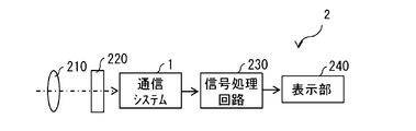
- FIG. 20 shows an example of a schematic configuration of an imaging system 2 including a communication system 1 according to the above embodiment and a modified example thereof.
- the imaging system 2 includes, for example, an optical system 210, a shutter device 220, a communication system 1, a signal processing circuit 230, and a display unit 240.
- the optical system 210 forms an image light (incident light) from the subject on the imaging surface of the communication system 1 (image sensor 11).
- the shutter device 220 is arranged between the optical system 210 and the image pickup system 2 and controls the light irradiation period and the light blocking period for the communication system 1 (image sensor 11).
- the communication system 1 receives the image light (incident light) incident from the outside by the image sensor 11, and outputs a pixel signal corresponding to the received image light (incident light) to the signal processing circuit 230.
- the signal processing circuit 230 processes the pixel signal input from the communication system 1 to generate video data.
- the signal processing circuit 230 further generates a video signal corresponding to the generated video data and outputs the video signal to the display unit 240.
- the display unit 240 displays an image based on the image signal input from the signal processing circuit 230.
- the communication system 1 according to the above embodiment and its modified example is applied to the imaging system 2.
- appropriate communication can be performed according to the capacity and speed of the data to be transmitted, so that it is possible to provide an imaging system 2 having high imaging image quality.
- the technology according to the present disclosure can be applied to various products.
- the technology according to the present disclosure is realized as a device mounted on a moving body of any kind such as an automobile, an electric vehicle, a hybrid electric vehicle, a motorcycle, a bicycle, a personal mobility, an airplane, a drone, a ship, and a robot. You may.
- FIG. 21 is a block diagram showing a schematic configuration example of a vehicle control system, which is an example of a mobile control system to which the technology according to the present disclosure can be applied.
- the vehicle control system 12000 includes a plurality of electronic control units connected via the communication network 12001.
- the vehicle control system 12000 includes a drive system control unit 12010, a body system control unit 12020, an outside information detection unit 12030, an in-vehicle information detection unit 12040, and an integrated control unit 12050.
- a microcomputer 12051, an audio image output unit 12052, and an in-vehicle network I / F (interface) 12053 are shown as a functional configuration of the integrated control unit 12050.
- the drive system control unit 12010 controls the operation of the device related to the drive system of the vehicle according to various programs.
- the drive system control unit 12010 provides a driving force generator for generating the driving force of the vehicle such as an internal combustion engine or a driving motor, a driving force transmission mechanism for transmitting the driving force to the wheels, and a steering angle of the vehicle. It functions as a control device such as a steering mechanism for adjusting and a braking device for generating a braking force of a vehicle.
- the body system control unit 12020 controls the operation of various devices mounted on the vehicle body according to various programs.
- the body system control unit 12020 functions as a keyless entry system, a smart key system, a power window device, or a control device for various lamps such as a head lamp, a back lamp, a brake lamp, a winker, or a fog lamp.
- the body system control unit 12020 may be input with radio waves transmitted from a portable device that substitutes for the key or signals of various switches.
- the body system control unit 12020 receives inputs of these radio waves or signals and controls a vehicle door lock device, a power window device, a lamp, and the like.
- the vehicle outside information detection unit 12030 detects information outside the vehicle equipped with the vehicle control system 12000.
- the imaging unit 12031 is connected to the vehicle exterior information detection unit 12030.
- the vehicle outside information detection unit 12030 causes the image pickup unit 12031 to capture an image of the outside of the vehicle and receives the captured image.
- the vehicle exterior information detection unit 12030 may perform object detection processing or distance detection processing such as a person, a vehicle, an obstacle, a sign, or a character on the road surface based on the received image.
- the imaging unit 12031 is an optical sensor that receives light and outputs an electric signal according to the amount of the light received.
- the image pickup unit 12031 can output an electric signal as an image or can output it as distance measurement information. Further, the light received by the imaging unit 12031 may be visible light or invisible light such as infrared light.
- the in-vehicle information detection unit 12040 detects the in-vehicle information.
- a driver state detection unit 12041 that detects the driver's state is connected to the in-vehicle information detection unit 12040.
- the driver state detection unit 12041 includes, for example, a camera that images the driver, and the in-vehicle information detection unit 12040 determines the degree of fatigue or concentration of the driver based on the detection information input from the driver state detection unit 12041. It may be calculated, or it may be determined whether the driver is dozing.
- the microcomputer 12051 calculates the control target value of the driving force generator, the steering mechanism, or the braking device based on the information inside and outside the vehicle acquired by the outside information detection unit 12030 or the inside information detection unit 12040, and the drive system control unit.
- a control command can be output to 12010.
- the microcomputer 12051 realizes ADAS (Advanced Driver Assistance System) functions including vehicle collision avoidance or impact mitigation, follow-up driving based on inter-vehicle distance, vehicle speed maintenance driving, vehicle collision warning, vehicle lane deviation warning, and the like. It is possible to perform cooperative control for the purpose of.
- ADAS Advanced Driver Assistance System
- the microcomputer 12051 controls the driving force generator, the steering mechanism, the braking device, and the like based on the information around the vehicle acquired by the vehicle exterior information detection unit 12030 or the vehicle interior information detection unit 12040, so that the driver can control the vehicle. It is possible to perform coordinated control for the purpose of automatic driving, etc., which runs autonomously without depending on the operation.
- the microcomputer 12051 can output a control command to the body system control unit 12020 based on the information outside the vehicle acquired by the vehicle exterior information detection unit 12030.
- the microcomputer 12051 controls the headlamps according to the position of the preceding vehicle or the oncoming vehicle detected by the external information detection unit 12030, and performs coordinated control for the purpose of anti-glare such as switching the high beam to the low beam. It can be carried out.
- the audio image output unit 12052 transmits the output signal of at least one of the audio and the image to the output device capable of visually or audibly notifying the passenger or the outside of the vehicle of the information.
- an audio speaker 12061, a display unit 12062, and an instrument panel 12063 are exemplified as output devices.
- the display unit 12062 may include, for example, at least one of an onboard display and a heads-up display.
- FIG. 22 is a diagram showing an example of the installation position of the imaging unit 12031.
- the vehicle 12100 has imaging units 12101, 12102, 12103, 12104, 12105 as imaging units 12031.
- the imaging units 12101, 12102, 12103, 12104, 12105 are provided at positions such as the front nose, side mirrors, rear bumpers, back doors, and the upper part of the windshield in the vehicle interior of the vehicle 12100, for example.
- the image pickup unit 12101 provided on the front nose and the image pickup section 12105 provided on the upper part of the windshield in the vehicle interior mainly acquire an image in front of the vehicle 12100.
- the imaging units 12102 and 12103 provided in the side mirrors mainly acquire images of the side of the vehicle 12100.
- the imaging unit 12104 provided on the rear bumper or the back door mainly acquires an image of the rear of the vehicle 12100.
- the images in front acquired by the imaging units 12101 and 12105 are mainly used for detecting a preceding vehicle or a pedestrian, an obstacle, a traffic light, a traffic sign, a lane, or the like.
- FIG. 22 shows an example of the photographing range of the imaging units 12101 to 12104.
- the imaging range 12111 indicates the imaging range of the imaging unit 12101 provided on the front nose
- the imaging ranges 12112 and 12113 indicate the imaging ranges of the imaging units 12102 and 12103 provided on the side mirrors, respectively
- the imaging range 12114 indicates the imaging range of the imaging units 12102 and 12103.
- the imaging range of the imaging unit 12104 provided on the rear bumper or the back door is shown. For example, by superimposing the image data captured by the imaging units 12101 to 12104, a bird's-eye view image of the vehicle 12100 as viewed from above can be obtained.
- At least one of the imaging units 12101 to 12104 may have a function of acquiring distance information.
- at least one of the image pickup units 12101 to 12104 may be a stereo camera composed of a plurality of image pickup elements, or an image pickup element having pixels for phase difference detection.
- the microcomputer 12051 has a distance to each three-dimensional object within the imaging range 12111 to 12114 based on the distance information obtained from the imaging units 12101 to 12104, and a temporal change of this distance (relative velocity with respect to the vehicle 12100). By obtaining can. Further, the microcomputer 12051 can set an inter-vehicle distance to be secured in front of the preceding vehicle in advance, and can perform automatic braking control (including follow-up stop control), automatic acceleration control (including follow-up start control), and the like. In this way, it is possible to perform coordinated control for the purpose of automatic driving or the like in which the vehicle travels autonomously without depending on the operation of the driver.
- automatic braking control including follow-up stop control
- automatic acceleration control including follow-up start control
- the microcomputer 12051 converts three-dimensional object data related to a three-dimensional object into two-wheeled vehicles, ordinary vehicles, large vehicles, pedestrians, electric poles, and other three-dimensional objects based on the distance information obtained from the imaging units 12101 to 12104. It can be classified and extracted and used for automatic avoidance of obstacles. For example, the microcomputer 12051 distinguishes obstacles around the vehicle 12100 into obstacles that can be seen by the driver of the vehicle 12100 and obstacles that are difficult to see. Then, the microcomputer 12051 determines the collision risk indicating the risk of collision with each obstacle, and when the collision risk is equal to or higher than the set value and there is a possibility of collision, the microcomputer 12051 is used via the audio speaker 12061 or the display unit 12062. By outputting an alarm to the driver and performing forced deceleration and avoidance steering via the drive system control unit 12010, driving support for collision avoidance can be provided.
- At least one of the imaging units 12101 to 12104 may be an infrared camera that detects infrared rays.
- the microcomputer 12051 can recognize a pedestrian by determining whether or not a pedestrian is present in the captured image of the imaging units 12101 to 12104.
- pedestrian recognition includes, for example, a procedure for extracting feature points in an image captured by an imaging unit 12101 to 12104 as an infrared camera, and pattern matching processing for a series of feature points indicating the outline of an object to determine whether or not the pedestrian is a pedestrian. It is done by the procedure to determine.
- the audio image output unit 12052 When the microcomputer 12051 determines that a pedestrian is present in the captured images of the imaging units 12101 to 12104 and recognizes the pedestrian, the audio image output unit 12052 outputs a square contour line for emphasizing the recognized pedestrian.
- the display unit 12062 is controlled so as to superimpose and display. Further, the audio image output unit 12052 may control the display unit 12062 so as to display an icon or the like indicating a pedestrian at a desired position.
- the above is an example of a mobile control system to which the technology according to the present disclosure can be applied.
- the technique according to the present disclosure can be applied to the imaging unit 12031 among the configurations described above.
- the imaging system 2 can be applied to the imaging unit 12031.
- the technique according to the present disclosure to the image pickup unit 12031, a high-quality photographed image can be obtained, so that highly accurate control using the photographed image can be performed in the moving body control system.
- the present disclosure may have the following structure.
- a determination unit that determines whether or not a retransmission request is possible based on the priority specified for each area in the frame, and A communication device including a transmission unit that generates retransmission request data and transmits it to another communication device when the determination unit can request a retransmission.
- the communication device according to (1) further comprising a register in which the number of retransmittables according to the priority is set for each area.
- the determination unit determines that a retransmission request is possible when the number of retransmission requests actually made in each of the areas does not exceed the number of retransmission requests.
- the receiving unit that receives the retransmission request data and A transmitter that sends data to other communication devices, A holding unit that holds the data transmitted from the transmitting unit as transmitted data, and a holding unit.
- a communication device including a control unit that controls retransmission of the transmitted data based on the retransmission request data.
- a determination unit that determines whether or not to retransmit the transmitted packet based on the priority specified for each area in the frame, and A communication device including a transmission unit that transmits the transmitted packet to another communication device when the determination unit can retransmit the transmitted packet.
- the determination unit determines that the transmitted packet can be retransmitted when the number of retransmission requests actually made for each area does not exceed the number of retransmissions specified for each area.
- Communication device (12) The determination unit determines that the transmitted packet can be retransmitted when the number of retransmission requests actually made in the frame does not exceed the number of retransmissions specified for the frame (10).
- the communication device according to (11).
- a communication system including a transmitting device and a receiving device, which communicates between the transmitting device and the receiving device.
- the receiving device is In the retransmission control, a determination unit that determines whether or not a retransmission request is possible based on the priority specified for each area in the frame, and When the determination unit can request a retransmission, it has a first transmission unit that generates retransmission request data and transmits the data to the transmission device.
- the transmitter is A receiving unit that receives the retransmission request data and A second transmitter that transmits data to the receiver, A holding unit that holds the data transmitted from the second transmitting unit as transmitted data, and a holding unit.
- a communication system having a control unit that controls retransmission of the transmitted data based on the retransmission request data.
- a communication system including a transmitting device and a receiving device, which communicates between the transmitting device and the receiving device.
- the receiving device has a first transmitting unit that generates retransmission request data and transmits the retransmission request data to the transmitting device in retransmission control.
- the transmitter is A receiving unit that receives the retransmission request data and A second transmitter that transmits data to the receiver, A holding unit that holds the data transmitted from the second transmitting unit as transmitted data, and a holding unit. It has a determination unit for determining whether or not the transmitted data can be resent based on the retransmission request data and the priority defined for each area in the frame.
- the second transmission unit is a communication system that transmits the transmitted packet to the receiving device when the determination unit can retransmit the transmitted packet.
- the retransmission control it is determined whether or not the retransmission request is possible based on the priority defined for each area in the frame, and if the retransmission request is possible, the retransmission is performed. Since the request data is generated and transmitted to another communication device, it is possible to prevent the delay from spreading after the next frame. As a result, the desired frame rate can be maintained.
- the retransmission control when the retransmission request data is received, the retransmission control of the transmitted data held in the holding unit is performed based on the retransmission request data. Therefore, it is possible to prevent the delay from spreading after the next frame. As a result, the desired frame rate can be maintained.
- the retransmission control it is determined whether or not the transmitted packet can be retransmitted based on the priority defined for each area in the frame, and the transmitted packet is retransmitted. If it is possible or not, the transmitted packet is transmitted to another communication device, so that it is possible to prevent the delay from spreading after the next frame. As a result, the desired frame rate can be maintained.
- the retransmission control it is determined whether or not the retransmission request is possible based on the priority defined for each area in the frame, and if the retransmission request is possible, the retransmission is performed. Since the request data is generated and transmitted from the transmitting device to the receiving device, it is possible to prevent the delay from spreading after the next frame. As a result, the desired frame rate can be maintained.
- the retransmission control it is determined whether or not the transmitted packet can be retransmitted based on the priority defined for each area in the frame, and the transmitted packet is retransmitted. If it is possible or not, the transmitted packet is transmitted from the transmitting device to the receiving device, so that it is possible to prevent the delay from spreading after the next frame. As a result, the desired frame rate can be maintained.
Landscapes
- Engineering & Computer Science (AREA)
- Computer Networks & Wireless Communication (AREA)
- Signal Processing (AREA)
- Detection And Prevention Of Errors In Transmission (AREA)
- Communication Control (AREA)
Priority Applications (3)
| Application Number | Priority Date | Filing Date | Title |
|---|---|---|---|
| US17/906,724 US12149366B2 (en) | 2020-03-26 | 2021-03-18 | Communication device and communication system for retransmission control |
| JP2022510051A JP7571121B2 (ja) | 2020-03-26 | 2021-03-18 | 通信装置および通信システム |
| CN202180022294.6A CN115315913B (zh) | 2020-03-26 | 2021-03-18 | 通信装置和通信系统 |
Applications Claiming Priority (2)
| Application Number | Priority Date | Filing Date | Title |
|---|---|---|---|
| JP2020056057 | 2020-03-26 | ||
| JP2020-056057 | 2020-03-26 |
Publications (1)
| Publication Number | Publication Date |
|---|---|
| WO2021193374A1 true WO2021193374A1 (ja) | 2021-09-30 |
Family
ID=77891772
Family Applications (1)
| Application Number | Title | Priority Date | Filing Date |
|---|---|---|---|
| PCT/JP2021/011204 Ceased WO2021193374A1 (ja) | 2020-03-26 | 2021-03-18 | 通信装置および通信システム |
Country Status (5)
| Country | Link |
|---|---|
| US (1) | US12149366B2 (https=) |
| JP (1) | JP7571121B2 (https=) |
| CN (1) | CN115315913B (https=) |
| TW (1) | TWI900547B (https=) |
| WO (1) | WO2021193374A1 (https=) |
Citations (3)
| Publication number | Priority date | Publication date | Assignee | Title |
|---|---|---|---|---|
| JPS5666980A (en) * | 1979-11-05 | 1981-06-05 | Hitachi Denshi Ltd | Picture transmission correcting system |
| JP2005033424A (ja) * | 2003-07-10 | 2005-02-03 | Mitsubishi Electric Corp | 映像受信装置および映像送信装置 |
| JP2010056964A (ja) * | 2008-08-28 | 2010-03-11 | Canon Inc | 受信装置及びその制御方法、プログラム、記録媒体 |
Family Cites Families (14)
| Publication number | Priority date | Publication date | Assignee | Title |
|---|---|---|---|---|
| JP2801687B2 (ja) * | 1989-10-18 | 1998-09-21 | 株式会社リコー | ファクシミリ装置 |
| JP4153995B2 (ja) * | 1996-08-07 | 2008-09-24 | 松下電器産業株式会社 | 画像復号化符号化装置、画像符号化装置及び画像復号化装置 |
| KR100460970B1 (ko) * | 2002-01-10 | 2004-12-09 | 삼성전자주식회사 | 데이터 송수신 시스템 및 방법 |
| JP3796211B2 (ja) * | 2002-11-18 | 2006-07-12 | 松下電器産業株式会社 | 送信装置及び送信方法 |
| JP2006033507A (ja) * | 2004-07-16 | 2006-02-02 | Sony Corp | 遠隔編集システム、主編集装置、遠隔編集装置、編集方法、編集プログラム、及び記憶媒体 |
| JP4917563B2 (ja) * | 2008-03-26 | 2012-04-18 | 京セラ株式会社 | 無線通信システム、無線通信装置およびその制御方法 |
| JP6695739B2 (ja) | 2016-05-26 | 2020-05-20 | ソニーセミコンダクタソリューションズ株式会社 | 処理装置、画像センサ、およびシステム |
| JP2018032934A (ja) * | 2016-08-23 | 2018-03-01 | ルネサスエレクトロニクス株式会社 | 通信装置及び再送制御方法 |
| US10491651B2 (en) * | 2017-05-15 | 2019-11-26 | Omnivision Technologies, Inc. | Method and system for streaming low-delay high-definition video with partially reliable transmission |
| EP3874776B1 (en) * | 2018-10-31 | 2025-01-29 | Fraunhofer-Gesellschaft zur Förderung der angewandten Forschung e.V. | Proximity awareness in sidelink communications |
| JP7582951B2 (ja) * | 2019-01-09 | 2024-11-13 | インターデイジタル パテント ホールディングス インコーポレイテッド | 超高信頼送信の拡張制御シグナリングのための方法、装置およびシステム |
| US11706662B2 (en) * | 2019-01-11 | 2023-07-18 | Qualcomm Incorporated | Techniques for determining a number of (re)transmissions in wireless communications |
| CN113875302B (zh) * | 2019-03-20 | 2025-04-22 | 株式会社Ntt都科摩 | 用户终端以及无线通信方法 |
| CN113767584B (zh) * | 2019-04-25 | 2024-01-26 | 松下电器(美国)知识产权公司 | 终端、基站、接收方法及发送方法 |
-
2021
- 2021-03-18 WO PCT/JP2021/011204 patent/WO2021193374A1/ja not_active Ceased
- 2021-03-18 TW TW110109677A patent/TWI900547B/zh active
- 2021-03-18 US US17/906,724 patent/US12149366B2/en active Active
- 2021-03-18 CN CN202180022294.6A patent/CN115315913B/zh active Active
- 2021-03-18 JP JP2022510051A patent/JP7571121B2/ja active Active
Patent Citations (3)
| Publication number | Priority date | Publication date | Assignee | Title |
|---|---|---|---|---|
| JPS5666980A (en) * | 1979-11-05 | 1981-06-05 | Hitachi Denshi Ltd | Picture transmission correcting system |
| JP2005033424A (ja) * | 2003-07-10 | 2005-02-03 | Mitsubishi Electric Corp | 映像受信装置および映像送信装置 |
| JP2010056964A (ja) * | 2008-08-28 | 2010-03-11 | Canon Inc | 受信装置及びその制御方法、プログラム、記録媒体 |
Non-Patent Citations (1)
| Title |
|---|
| MIPI ALLIANCE: "MIPI Alliance to Advance Autonomous Driving, other Automotive Applications with New Data Interface Specifications at 12-24 Gbps and Beyond", MIPI ALLIANCE, 2 August 2018 (2018-08-02), pages 1 - 4, XP055861244, Retrieved from the Internet <URL:https://www.mipi.org/node/1449> [retrieved on 20211115] * |
Also Published As
| Publication number | Publication date |
|---|---|
| TWI900547B (zh) | 2025-10-11 |
| US20230155750A1 (en) | 2023-05-18 |
| CN115315913A (zh) | 2022-11-08 |
| CN115315913B (zh) | 2025-08-01 |
| JPWO2021193374A1 (https=) | 2021-09-30 |
| JP7571121B2 (ja) | 2024-10-22 |
| TW202207684A (zh) | 2022-02-16 |
| US12149366B2 (en) | 2024-11-19 |
Similar Documents
| Publication | Publication Date | Title |
|---|---|---|
| JP7314798B2 (ja) | 撮像装置、画像処理装置、及び、画像処理方法 | |
| US11297268B2 (en) | Solid-state imaging element, imaging apparatus, and method of controlling solid-state imaging element | |
| US11076148B2 (en) | Solid-state image sensor, imaging apparatus, and method for controlling solid-state image sensor | |
| KR102716460B1 (ko) | 자율주행차량의 데이터 보안 방법 및 장치 | |
| CN115179863A (zh) | 移动体的控制装置及控制方法、存储介质以及车辆 | |
| CN113382159A (zh) | 用于共享相机设置控制的系统和方法 | |
| JP7571121B2 (ja) | 通信装置および通信システム | |
| US20260052319A1 (en) | Solid-state imaging device | |
| JPWO2018025570A1 (ja) | 通信装置、および通信システム | |
| KR20210090301A (ko) | 군집주행을 수행하는 차량 제어 | |
| JP7713441B2 (ja) | 通信システム | |
| US12088927B2 (en) | Imaging device and imaging method | |
| US11201997B2 (en) | Solid-state imaging device, driving method, and electronic apparatus | |
| WO2021131684A1 (ja) | 測距装置およびその制御方法、並びに、電子機器 | |
| WO2021124921A1 (ja) | 画像処理装置、画像処理方法、およびプログラム | |
| CN110493490B (zh) | 摄像装置及摄像系统 | |
| US20260127919A1 (en) | System and method for collision matching and information exchange | |
| US20250227100A1 (en) | Imaging devices, host devices, and method | |
| WO2025187390A1 (ja) | 撮像装置、撮像方法 | |
| CN121002892A (zh) | 光检测装置及光检测系统 | |
| WO2025047365A1 (ja) | 撮像装置、および故障検知方法 | |
| WO2025004532A1 (ja) | 異常検出回路、異常検出方法、および撮像システム |
Legal Events
| Date | Code | Title | Description |
|---|---|---|---|
| 121 | Ep: the epo has been informed by wipo that ep was designated in this application |
Ref document number: 21776428 Country of ref document: EP Kind code of ref document: A1 |
|
| ENP | Entry into the national phase |
Ref document number: 2022510051 Country of ref document: JP Kind code of ref document: A |
|
| NENP | Non-entry into the national phase |
Ref country code: DE |
|
| 122 | Ep: pct application non-entry in european phase |
Ref document number: 21776428 Country of ref document: EP Kind code of ref document: A1 |
|
| WWG | Wipo information: grant in national office |
Ref document number: 202180022294.6 Country of ref document: CN |