WO2021193123A1 - 制御システム、及び、制御方法 - Google Patents
制御システム、及び、制御方法 Download PDFInfo
- Publication number
- WO2021193123A1 WO2021193123A1 PCT/JP2021/009913 JP2021009913W WO2021193123A1 WO 2021193123 A1 WO2021193123 A1 WO 2021193123A1 JP 2021009913 W JP2021009913 W JP 2021009913W WO 2021193123 A1 WO2021193123 A1 WO 2021193123A1
- Authority
- WO
- WIPO (PCT)
- Prior art keywords
- unit
- user
- blower
- control system
- air
- Prior art date
- Legal status (The legal status is an assumption and is not a legal conclusion. Google has not performed a legal analysis and makes no representation as to the accuracy of the status listed.)
- Ceased
Links
Images





Classifications
-
- F—MECHANICAL ENGINEERING; LIGHTING; HEATING; WEAPONS; BLASTING
- F04—POSITIVE - DISPLACEMENT MACHINES FOR LIQUIDS; PUMPS FOR LIQUIDS OR ELASTIC FLUIDS
- F04D—NON-POSITIVE-DISPLACEMENT PUMPS
- F04D27/00—Control, e.g. regulation, of pumps, pumping installations or pumping systems specially adapted for elastic fluids
-
- F—MECHANICAL ENGINEERING; LIGHTING; HEATING; WEAPONS; BLASTING
- F24—HEATING; RANGES; VENTILATING
- F24F—AIR-CONDITIONING; AIR-HUMIDIFICATION; VENTILATION; USE OF AIR CURRENTS FOR SCREENING
- F24F11/00—Control or safety arrangements
- F24F11/70—Control systems characterised by their outputs; Constructional details thereof
- F24F11/72—Control systems characterised by their outputs; Constructional details thereof for controlling the supply of treated air, e.g. its pressure
- F24F11/74—Control systems characterised by their outputs; Constructional details thereof for controlling the supply of treated air, e.g. its pressure for controlling air flow rate or air velocity
-
- F—MECHANICAL ENGINEERING; LIGHTING; HEATING; WEAPONS; BLASTING
- F24—HEATING; RANGES; VENTILATING
- F24F—AIR-CONDITIONING; AIR-HUMIDIFICATION; VENTILATION; USE OF AIR CURRENTS FOR SCREENING
- F24F11/00—Control or safety arrangements
- F24F11/70—Control systems characterised by their outputs; Constructional details thereof
- F24F11/72—Control systems characterised by their outputs; Constructional details thereof for controlling the supply of treated air, e.g. its pressure
- F24F11/79—Control systems characterised by their outputs; Constructional details thereof for controlling the supply of treated air, e.g. its pressure for controlling the direction of the supplied air
-
- F—MECHANICAL ENGINEERING; LIGHTING; HEATING; WEAPONS; BLASTING
- F24—HEATING; RANGES; VENTILATING
- F24F—AIR-CONDITIONING; AIR-HUMIDIFICATION; VENTILATION; USE OF AIR CURRENTS FOR SCREENING
- F24F2120/00—Control inputs relating to users or occupants
- F24F2120/10—Occupancy
- F24F2120/12—Position of occupants
Definitions
- the present invention relates to a control system and a control method.
- Patent Document 1 discloses a technique for performing comfortable air conditioning control by detecting the position of a person in a room and controlling the temperature and airflow in the room according to the position of the person.
- Patent Document 1 performs comfortable air conditioning control according to a person.
- the present invention provides a control system and a control method capable of performing comfortable air conditioning control according to a person.
- the control system detects a plurality of blowers that blow air toward the corresponding points in a plurality of horizontally aligned places and a user existing in the direction in which the air is blown. Based on the detection unit, the derivation unit that derives the horizontal width of the user with respect to the plurality of air blowers based on the detection results from the detection unit, and the derivation unit that derives the horizontal width of the user. It is provided with a determination unit for determining the ventilation mode at both ends and the center in the horizontal direction, and a control unit for controlling the operation of each of the plurality of ventilation units based on the determined ventilation mode.
- the control method is a control method of a blower device including a plurality of blower portions for blowing air toward the corresponding points at a plurality of points arranged in a horizontal direction, from the blower device.
- a user existing in the direction in which the air is blown is detected, and based on the detection result, the horizontal width of the user with respect to the plurality of blowers is derived, and based on the derived width of the user.
- the blowing mode at both ends and the center of the horizontal width in the horizontal direction is determined, and the operation of each of the plurality of blowing portions is controlled based on the determined blowing mode.
- the program according to one aspect of the present invention is a program for causing a computer to execute the control method.
- a control system and a control method capable of performing comfortable air conditioning control according to a person are realized.
- FIG. 1 is a diagram showing an outline of a control system according to an embodiment.
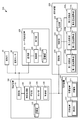
- FIG. 2 is a block diagram showing an example of the functional configuration of the control system according to the embodiment.
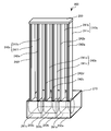
- FIG. 3 is a diagram showing an example of the configuration of the blower device according to the embodiment.
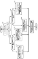
- FIG. 4 is a flowchart of an operation example 1 of the control system according to the embodiment.
- FIG. 5 is a diagram showing an example of ventilation control based on the width of the user.
- FIG. 6 is a flowchart of an operation example 2 of the control system according to the embodiment.
- FIG. 7 is a flowchart of an operation example 3 of the control system according to the embodiment.
- FIG. 8 is a flowchart of an operation example 4 of the control system according to the embodiment.
- FIG. 9 is a graph showing the results of Experimental Example 1.
- FIG. 10 is a graph showing the results of Experimental Example 2.
- FIG. 11 is a graph showing the results of Experimental Example 3.
- each figure is a schematic diagram and is not necessarily exactly illustrated. Further, in each figure, substantially the same configuration may be designated by the same reference numerals, and duplicate description may be omitted or simplified.
- FIG. 1 is a diagram showing an outline of a control system according to an embodiment.
- the control system 500 is a system for controlling the blower 200 based on the width of the user. As shown in FIG. 1, in the control system 500, in addition to the blower 200 arranged in the space where the user 1 exists, the information input by the user 1 using the user terminal device 400 (for example, the temperature desired by the user 1). Home devices such as the lighting device 310 and the sound device 320 may also be controlled based on the feeling of coldness and mood.
- the width of the user 1 is derived from the detection result from the detection unit 30 such as a camera.
- the control system 500 determines the blowing mode at both ends and the center of the width of the user 1, and controls the blowing from the blowing device 200 based on the determined blowing mode. Further, for example, the control system 500 may change the ventilation mode based on the information regarding the feeling of warmth and coldness desired by the user, which is input by the user 1 using the user terminal device 400 such as a smartphone. Further, for example, the control system 500 not only controls the air blown from the blower device 200 based on the information about the mood desired by the user 1, but also other devices arranged in the room such as the lighting device 310 and the sound device 320. The operation of (hereinafter, also referred to as a home device) may be controlled. Specific control examples will be described later.
- the width of the user 1 is the horizontal direction of the user 1 with respect to a plurality of blowers (for example, the first blower 240a, the second blower 240b, and the third blower 240c (see FIG. 3)) included in the blower 200. More specifically, it is the width of the user 1 in the arrangement direction of the plurality of blowers (first blower 240a, second blower 240b, third blower 240c) included in the blower 200. For example, when the user 1 faces the blower 200, the width of the user 1 is the shoulder width of the user 1, and when the user 1 faces the blower 200, the width of the user 1 is. The thickness of the body of the user 1. FIG.
- the blower 200 may be placed on the ceiling.
- the horizontal width of the user 1 with respect to the blower 200 is the horizontal width of the user 1 as seen from the ceiling, and more specifically, a plurality of blower portions (more specifically) of the blower 200 arranged on the ceiling. It is the width of the user 1 in the arrangement direction of the first blower unit 240a, the second blower unit 240b, and the third blower unit 240c).
- FIG. 2 is a block diagram showing an example of the functional configuration of the control system according to the embodiment.
- the control system 500 includes a detection unit 30, a control device 100, a blower device 200, a home device 300, and a user terminal device 400.
- the detection unit 30 is a sensor that detects the user 1.
- the detection unit 30 detects the user 1 existing in the direction in which the air is blown from the blower device 200.
- the detection unit 30 is, for example, a camera, and captures an image (specifically, a moving image) of the user 1.
- the camera is realized by a CMOS (Complementary Metal Oxide Semiconductor) image sensor or a CCD (Charge Coupled Device) image sensor.
- the detection unit 30 may be a distance measuring camera that captures a distance image, or may be an infrared sensor that detects the presence or absence of the user 1 in the detection range.
- the detection unit 30 may be installed in the indoor space or may be incorporated in the blower.
- the temperature sensor 50 measures the temperature of the indoor space in which the blower 200 is arranged. Specifically, the temperature sensor 50 senses the ambient temperature of the user 1. The temperature sensor 50 outputs the sensing data to the control device 100.
- the temperature sensor 50 may be incorporated in the blower device 200 or may be installed in an indoor space. Further, one or more temperature sensors 50 may be installed. In this case, one temperature sensor 50 is incorporated in the blower 200, and the remaining temperature sensors 50 are mounted on the ceiling, wall, pillar, or the like of the indoor space. It may be installed. For example, the measured values of the temperatures of the plurality of temperature sensors 50 are used for calculating the temperature distribution in the indoor space.
- the temperature sensor 50 may be realized by, for example, a temperature measuring element such as a thermistor or a thermocouple.
- the control system 500 may further include a humidity sensor (not shown) that senses the humidity of the environment around the user.
- the humidity sensor outputs the sensing data to the control device 100.
- the humidity sensor may be incorporated in the blower 200, may be incorporated in a humidifier (not shown) arranged in the room, or may be installed in the indoor space. Further, the humidity sensor may be a temperature / humidity sensor in which a temperature sensor and a humidity sensor are integrated on one chip.
- the control device 100 controls the blower device 200 based on the width of the user 1 derived from the detection result of the detection unit 30.
- the control device 100 may further control the blower device 200 based on the measured value of the temperature sensor 50.
- the control device 100 may further control the blower device 200 based on the information regarding the feeling of warmth and coldness input by the user 1.
- the control device 100 may be a local controller installed in or near the indoor space, or may be a circuit incorporated in the blower device 200.
- the control device 100 includes, for example, a communication unit 110, an information processing unit 120, and a storage unit 130.
- the communication unit 110 is a communication module (communication circuit) for the control device 100 to communicate with the detection unit 30, the temperature sensor 50, the blower device 200, the home device 300, and the user terminal device 400 via the local communication network. Is.
- the communication unit 110 acquires sensing data from each of the detection unit 30 and the temperature sensor 50, for example. Further, the communication unit 110 acquires the input information of the user 1 from the user terminal device 400.
- the communication performed by the communication unit 110 may be wired communication or wireless communication.
- the communication standard used for communication is also not particularly limited.
- the information processing unit 120 performs information processing for causing the blower device 200 to perform blower control.
- the information processing unit 120 has a derivation unit 122, a determination unit 124, and a control unit 126.
- the information processing unit 120 is realized by, for example, a processor, a microcomputer, or a dedicated circuit.
- the information processing unit 120 may be realized by a combination of two or more of a processor, a microcomputer, or a dedicated circuit.
- the lead-out unit 122 determines the horizontal width of the user 1 with respect to the plurality of blower units (for example, the first blower unit 240a, the second blower unit 240b, and the third blower unit 240c). Derived.
- the determination unit 124 determines the ventilation mode at both ends and the center of the width of the user 1 in the horizontal direction based on the width of the user 1 derived by the derivation unit 122.
- Examples of the blowing mode include blowing speed, blowing amount, blowing range, and periodic fluctuations (so-called fluctuations) of these parameters.
- the control unit 126 controls the operation of each of the plurality of blower units of the blower device 200 based on the blower mode determined by the determination unit 124.
- the specific ventilation pattern realized based on the ventilation mode may be, for example, a ventilation pattern in which the ratio of the air volume at both ends of the width of the user 1 to the air volume of the air at the center of the width of the user 1 is large.
- the ventilation pattern may be such that the ratio of the air volume at the centers of both ends of the user 1 to the air volume at the center of the width of the user 1 is small.
- the ventilation pattern may be a ventilation pattern in which the air blown to the center of the width of the user 1 has fluctuations and the amount of air blown to both ends of the width of the user 1 is maintained at a constant level.
- the ventilation pattern is not limited to the above example.
- the storage unit 130 contains sensing data acquired by the control device 100 from various sensors such as the detection unit 30 and the temperature sensor 50, and a computer program executed by the information processing unit 120 (for example, an application program for controlling the blower device 200). ) Etc. are stored in the storage device. Further, the storage unit 130 may store, for example, a ventilation mode database (not shown) and a control pattern database (not shown). In the ventilation mode database, the width of the user and the ventilation mode at both ends and the center of the width of the user (hereinafter, simply referred to as the ventilation mode) may be stored in association with each other. Further, the control pattern database may store the ventilation mode, the distance from the ventilation unit to the user, and the control pattern of the ventilation unit in association with each other.
- a hot / cold feeling-blowing mode database (not shown) is stored in which information on the hot / cold feeling desired by the user and the air blowing mode are linked and stored. May be good.
- the storage unit may store a mood-blower mode database (not shown) in which information about the mood desired by the user and the blast mode are linked and stored. These warm / cold feeling-blower mode database and mood-blower mode database may be combined into one database. Further, the lighting mode and the acoustic mode may be stored in the warm / cold feeling-blower mode database and the mood-blower mode database, respectively.
- the storage unit 130 is realized by, for example, a semiconductor memory or the like.
- the storage unit 130 may be a storage unit on the cloud server.
- the control system 500 includes a humidifying unit (not shown)
- the heating / cooling feeling-blower mode database and the mood-blower mode database may store the humidifying mode in addition to the lighting mode and the acoustic mode, respectively. good. Details of the lighting mode, acoustic mode, and humidification mode will be described later.
- the blower 200 includes a plurality of blowers, and independently controls the amount of air sent from each blower (that is, the air volume), the speed of the air sent out (that is, the wind speed), and periodic fluctuations thereof. It is a device that can be controlled.
- the blower 200 includes, for example, a communication unit 210, a control unit 220, a storage unit 230, a first blower unit 240a, a second blower unit 240b, and a third blower unit 240c. Further, as shown in FIG. 2, the blower 200 has a temperature adjusting unit (for example, a first temperature adjusting unit 250a, a second temperature adjusting unit 250b, a third temperature adjusting unit 250c) such as a heat exchanger.
- a temperature adjusting unit for example, a first temperature adjusting unit 250a, a second temperature adjusting unit 250b, a third temperature adjusting unit 250c
- FIG. 3 is a diagram showing an example of the configuration of the blower device according to the embodiment.
- the blower 200 includes a housing 270, a plurality of blowers arranged on the housing 270, and a partition plate 280.
- the plurality of blowers are the first blower 240a, the second blower 240b, and the third blower 240c.
- the housing 270 houses high-pressure air adjusting units 260a, 260b, 260c (hereinafter, 260a to 260c) corresponding to each blowing unit.
- the high-pressure air adjusting units 260a to 260c include a suction port (not shown) for taking in air from the outside of the housing 270, an impeller for generating high-pressure air (not shown), and a motor for driving the impeller (not shown).
- High-pressure air generating units 261a, 261b, and 261c High-pressure air generating units 261a, 261b, and 261c, the above-mentioned temperature adjusting unit (not shown in FIG. 3), and a nozzle (not shown) for delivering high-pressure air to each outlet.
- the partition plate 280 partitions a gap, which will be described later.
- the blower 200 may or may not be provided with the partition plate 280 as a part of the gap.
- the first blower section 240a, the second blower section 240b, and the third blower section 240c blow air toward each of the three corresponding locations arranged in the horizontal direction.
- the blower 200 may include two blowers or four or more blowers.
- the first blower 240a sends wind to the right end of the width of the user 1 (see FIG. 1) facing the blower 200, and the second blower 240b.
- each blower blows the wind so that the wind hits a range from one end to the center of the width of the user 1, for example.
- the first blower portion 240a includes a nozzle 241a having an outlet 242a for blowing high-pressure air on one side surface (here, the surface on the front side of the paper surface), and a nozzle 241b having an outlet 242b on one side surface.
- the one side surface is arranged with a gap so as to be flush with each other.
- the second blower section 240b and the third blower section 240c are the same as those of the first blower section 240a.
- a gap is formed in the second blower portion 240b so that the nozzle 241c having the outlet 242c on one side surface and the nozzle 241d having the outlet 242d on one side surface are flush with each other.
- the nozzle 241e having the outlet 242e on one side surface and the nozzle 241f having the outlet 242f on one side surface are flush with each other. It is placed open.
- the outlets 242a to 242f are uniformly formed on one side surface, but for example, the outlets 242a to 242f each have a plurality of outlets such as the upper outlet and the lower outlet. It may be composed of outlets, and the size (here, vertical width) of the outlet of each nozzle may be different.
- a wind direction plate (not shown) for adjusting the wind direction may be installed at each air outlet.
- the blower 200 may control the direction of the air blown from the blower by adjusting the direction of the high-pressure air blown from the outlet according to the control signal from the control device 100. For example, when the control device 100 determines the blowing mode based on the movement of the user 1 from the detection result from the detection unit 30, the blowing device 200 may perform the blowing control according to the movement of the user 1. Further, in the blower device 200, for example, when the control device 100 determines the blower mode based on the vertical width of the user 1 from the detection result from the detection unit 30, the blower device 200 adds the blower control in the horizontal width direction of the user 1. Therefore, the ventilation control in the vertical width direction may be performed.
- the first blower section 240a, the second blower section 240b, and the third blower section 240c are placed in the gaps between the two nozzles 241a and 241b, 241c and 241d, 241e, and 241f by the high-pressure air blown from the outlets 242a to 242f, respectively.
- the attracted air is blown toward each of the three horizontally aligned locations.
- the operation of each of the first blower unit 240a, the second blower unit 240b, and the third blower unit 240c is controlled by the control unit 220 based on the control signal from the control device 100.
- the blower 200 is blown from the first blower 240a by adjusting the amount of high-pressure air blown from the outlets 242a and 242b of the first blower 240a according to the control signal from the control device 100.
- the amount of air may be controlled.
- the ventilation mode for example, air volume and wind speed
- the ventilation mode in a part of the width (for example, the right end) of the user 1 corresponding to the first blower unit 240a can be changed. It will be adjusted.
- each of the first blower section 240a, the second blower section 240b, and the third blower section 240c may further have a humidifying section (not shown). This makes it possible to adjust the humidity of the air sent from the blower 200.
- the humidifying unit includes, for example, a water storage container for storing water and a filter for retaining water in the water storage container. The details of the operation of the humidifying portion will be described through an operation example.
- the communication unit 210, the control unit 220, and the storage unit 230 of the blower 200 will be described.
- the communication unit 210 is a communication circuit for the blower 200 to communicate with the control device 100.
- the communication unit 210 may be, for example, a wireless communication circuit that performs wireless communication, or a wired communication circuit that performs wired communication.
- the communication standard for communication performed by the communication unit 210 is not particularly limited.
- the control unit 220 performs information processing related to the control of the blower device 200.
- the control unit 220 is realized by, for example, a microcomputer, but may be realized by a processor or a dedicated circuit.
- the storage unit 230 is a storage device that stores a program executed by the control unit 220 (for example, an application program for controlling the blower device 200).
- the storage unit 230 is realized by, for example, a semiconductor memory or the like.
- the home device 300 is a device other than the blower device 200 installed in the indoor space, and is a device to be controlled by the control device 100. As described above, the operation of the home device 300 such as the lighting device 310 and the sound device 320 is based on the information input by the user 1 using the user terminal device 400 (for example, the feeling of warmth and coldness and mood desired by the user 1). It is controlled by the control device 100. More specifically, the control device 100 controls the operation of the home device 300 based on a mode (for example, a lighting mode or an acoustic mode) determined based on the above information.
- the home device 300 includes, for example, a communication module (communication circuit) for communicating with the control device 100, and operates according to a control signal received from the control device 100.
- the home device 300 includes, for example, a lighting device 310 and an audio device 320.
- the lighting device 310 illuminates the room. More specifically, the lighting device 310 receives a control signal from the control device 100 that controls at least one of the chromaticity and intensity of the light emitted from the lighting unit 311 and illuminates the room according to the control signal. ..
- the control signal is generated based on the illumination mode determined based on the information input by the user 1 using the user terminal device 400. Examples of the illumination mode include the color temperature of the light emitted from the illumination unit 311 or the numerical value of the output.
- the specific lighting pattern realized based on the lighting mode is, for example, a lighting pattern in which the center is bright and gradually becomes darker as it spreads from the center to the outside when the position of the user 1 is set to the center of the lighting area.
- the illumination pattern is, for example, an illumination pattern having uniform brightness over the entire illumination region, an illumination pattern in which the entire illumination region gradually becomes brighter from the off state, or an overall brightness of the illumination region gradually increasing. It may be an illumination pattern that becomes dark and turns off.
- the lighting pattern is not limited to the above example.
- the lighting device 310 is, for example, a ceiling light, but the specific embodiment of the lighting device 310 is not particularly limited.
- the lighting device 310 may be a downlight, a pendant light, a spotlight, a bracket light, or the like.
- the sound device 320 is a device including a sound unit 321 such as a speaker or earphones.
- the sound device 320 may reproduce the sound in a predetermined space such as a room via a speaker, or may reproduce the sound through an earphone attached to the user.
- the sound device 320 receives a control signal for controlling at least one of the type, volume, and playback speed of the sound reproduced from the sound unit 321 from the control device 100, and reproduces the sound according to the control signal.
- the control signal is generated based on an acoustic mode determined based on the information input by the user 1 using the user terminal device 400. Examples of the acoustic mode include the intensity, reproduction speed, modulation, and the like of the sound reproduced from the acoustic unit 321.
- the specific acoustic pattern realized based on the acoustic aspect is, for example, an acoustic pattern that reproduces a sound according to a predetermined rhythm or tempo, an acoustic pattern that reproduces a sound according to a predetermined music, or a bird's song or a stream. It may be an acoustic pattern that reproduces a natural sound such as a murmuring.
- the acoustic pattern is not limited to the above example.
- the home device 300 is not limited to the above example.
- the home device 300 may include a humidifier, an aroma diffuser, and the like.
- a humidifier is a device equipped with a humidifying unit that adjusts the humidity of the air in the indoor space.
- the humidifier receives a control signal from the control device 100 that controls at least one of the amount of humidified air discharged from the humidifying section, the discharge time, and the number of times of discharge, and the humidity of the air in the indoor space according to the control signal.
- the control signal may be generated based on a humidification mode determined based on the information input by the user 1 using the user terminal device 400. Further, when the control system 500 includes a humidity sensor (not shown), the control signal may be generated based on a humidification mode determined based on the ambient humidity of the user 1 sensed by the humidity sensor. ..
- Examples of the humidification mode include humidification of the air to be humidified by the humidifying portion, the amount of humidified air delivered, the humidification time, and the like.
- the specific humidification pattern realized based on the humidification mode is, for example, a humidification pattern that maintains a preset humidity according to the temperature of the air in the indoor space, a humidification pattern that periodically switches the humidity, or a humidification pattern. , It may be a humidification pattern that adjusts the humidity based on the difference between the user's surface temperature and the user's ambient temperature.
- the humidification pattern is not limited to the above example.
- the aroma diffuser generates a scent in the indoor space and provides the user 1 with the sentimental effect desired by the user 1.
- the aroma diffuser receives a control signal output from the control unit based on the fragrance mode determined by the determination unit, and generates a scent according to the control signal.
- the fragrance mode include the type, intensity, fragrance time, fragrance frequency, and the like.
- the specific fragrance pattern realized by the fragrance mode may be stored in the storage unit 130 in association with the sentimental effect desired by the user 1.
- the user terminal device 400 is, for example, a portable information terminal such as a smartphone or a tablet terminal, but may be a stationary information terminal such as a personal computer.
- the communication unit 410 is a communication circuit for the user terminal device 400 to communicate with the control device 100.
- the communication unit 410 is, for example, a wireless communication circuit that performs wireless communication.
- the communication standard for communication performed by the communication unit 410 is not particularly limited.
- the reception unit 440 receives an input operation performed to transmit the information on the feeling of warmth or coldness felt or desired by the user 1 and the information on the mood felt or desired by the user 1 to the control device 100.
- the reception unit 440 may be realized by, for example, a touch panel, a display panel, a hardware button, a microphone, or the like.
- the touch panel may be, for example, a capacitive touch panel or a resistive touch panel.
- the display panel has an image display function and a function of accepting manual input by the user, and accepts an input operation to a numeric keypad image displayed on a display panel such as a liquid crystal panel or an organic EL (Electroluminescence) panel.
- the microphone accepts the user's voice input.
- the control unit 420 controls the display of the image on the reception unit 440, performs voice recognition processing of the voice input by the user 1, and the like.
- the control unit 420 may be realized by, for example, a microcomputer or a processor.
- the storage unit 430 is a storage device that stores a dedicated application program or the like for execution by the control unit 420.
- the storage unit 430 is realized by, for example, a semiconductor memory or the like.
- reception unit 440 shows an example of being a component of the user terminal device 400
- the reception unit 440 may be integrated with at least one of the other components of the control system 500. ..
- the reception unit 440 may be incorporated in the blower device 200, or may be incorporated in a remote controller (not shown).
- FIG. 4 is a flowchart of an operation example 1 of the control system according to the embodiment.
- FIG. 5 is a diagram showing an example of ventilation control based on the width of the user.
- the information processing unit 120 acquires the detection result from the detection unit 30 via the communication unit 110 (S11).
- the detection unit 30 detects a user who exists in the direction in which air is blown from the blower device 200.
- the detection unit 30 is, for example, a distance measuring camera, and outputs a distance image to the control device 100.
- the detection unit 30 may be a thermal image camera, an ultrasonic sensor, an infrared sensor, or the like.
- the detection unit 30 is not limited to one, and may be composed of two or more sensors.
- the derivation unit 122 is horizontal to the first blower unit 240a, the second blower unit 240b, and the third blower unit 240c based on the detection result (for example, data such as a distance image) from the detection unit 30.
- the horizontal width in the direction is derived (S12).
- the out-licensing unit 122 also derives the distance from the blower 200 to the user.
- FIG. 5 shows the width of the user when the user faces the blower 200.
- FIG. 5A shows a slender user 1a
- FIG. 5B shows a thicker user 1b.
- the widths W 1 and W 2 of the users 1a and 1b are the horizontal widths of the users 1a and 1b with respect to the blower 200, respectively.
- the widths W 1 and W 2 of the users 1a and 1b are the widths of the users 1a and 1b in the horizontal direction as seen from the blower 200, respectively, and the first blower 240a and the second blower of the blower 200, respectively.
- the width of the users 1a and 1b is the width of the users 1a and 1b in the arrangement direction of the 240b and the third blower unit 240c.
- the widths W 1 and W 2 of the users 1a and 1b are shoulder widths.
- the width of the users 1a and 1b is the thickness of the user (width from chest to back).
- the determination unit 124 determines the ventilation mode at both ends and the center of the width of the user based on the width of the user derived by the derivation unit 122 (S13). For example, the determination unit 124 may determine the above-mentioned ventilation mode with reference to the ventilation mode database (not shown) based on the width of the user. For example, in the ventilation mode database, the width of the user and the ventilation mode at both ends and the center of the width of the user are stored in association with each other. As described above, the blowing mode includes the blowing speed, the blowing amount, the blowing range, or the periodic fluctuation (so-called fluctuation) of these parameters.
- the control unit 126 controls the operation of each of the plurality of ventilation units based on the ventilation mode determined by the determination unit 124 (S14). For example, the control unit 126 determines and determines the control pattern of each ventilation unit based on the ventilation mode determined by the determination unit 124, taking into consideration the distance from each ventilation unit to the corresponding portion in the width of the user. The operation of each blower is controlled according to the control pattern. At this time, the control unit 126 may determine the control pattern by referring to the control pattern database (not shown). For example, in the control pattern database, the ventilation mode, the distance from the ventilation unit to the user, and the control pattern of the ventilation unit are linked. The ventilation mode database and the control pattern database may be stored in the storage unit 130 or may be stored in the storage unit on the server.
- the control unit 126 adjusts the amount of high-pressure air blown from the outlet in controlling the operation of each of the plurality of blower units (for example, the first blower unit 240a, the second blower unit 240b, and the third blower unit 240c). By doing so, the amount of air blown is controlled.
- the control unit 126 adjusts the amount of high-pressure air blown from the two outlets 242a and 242b of the first blower unit 240a, thereby causing the first blower.
- the amount of air attracted to the gap between the two nozzles 241a and 241b of the unit 240a is controlled.
- the control unit 126 controls the amount of air blown from the first blower unit 240a.
- the control unit 126 is blown out from the air outlet of each air blowing unit according to the widths W 1 and W 2 of the users 1a and 1b.
- the control unit 126 can control the blower range, blower strength, wind speed, and the like of the air blown from each blower unit.
- the ventilation control based on the width of the user is not limited to the example shown in FIG.
- the derivation unit 122 derives the vertical width of the user in the horizontal direction (here, the vertical width in the height direction of the user) from the detection result of the detection unit 30, and the determination unit 124 is the user.
- the ventilation mode may be determined based on the vertical width of the user.
- the determination unit 124 adjusts the ventilation range and the ventilation intensity in the vertical width direction at both ends and the center of the width of the user when the user is sitting on a chair or the like and when the user is standing. The aspect may be determined.
- the control unit 126 controls the direction of the air blown from each of the blower units by adjusting the direction of the high-pressure air blown from each of the outlets of the plurality of blower units based on the blower mode. do.
- the control unit 126 blows air by adjusting the amount of high-pressure air blown out from each outlet so that the amount of air attracted to the gap between adjacent nozzles or the gradient of velocity is created.
- the direction of the air may be controlled.
- each air outlet may have a wind direction adjusting plate for adjusting the direction of high-pressure air, and the control unit 126 controls the direction of the air direction adjusting plate of each air outlet to control the high pressure.
- the direction of the air may be adjusted.
- the derivation unit 122 derives the surface temperature of the user (for example, the skin temperature of the exposed skin) from the detection result of the detection unit 30, and the determination unit 124 determines the user.
- the ventilation mode may be determined based on the surface temperature of the user. For example, when the surface temperature of the user is high, the determination unit 124 may determine the blowing mode in which the amount of air to be blown is increased and the blowing speed is increased. On the other hand, when the surface temperature of the user is low, the determination unit 124 may determine the blowing mode in which the amount of air to be blown is reduced and the blowing speed is weakened.
- FIG. 6 is a flowchart of an operation example 2 of the control system according to the embodiment. Here, the points different from the operation example 1 will be mainly described.
- the information processing unit 120 acquires the detection result from the detection unit 30 and the sensing data from the temperature sensor 50 via the communication unit 110 (S21).
- the derivation unit 122 is horizontal to the first blower unit 240a, the second blower unit 240b, and the third blower unit 240c based on the detection result (for example, data such as a distance image) from the detection unit 30.
- the horizontal width in the direction is derived, and the temperature around the user is derived based on the sensing data from the temperature sensor 50 (S22).
- the out-licensing unit 122 also derives the distance from the blower 200 to the user.
- the determination unit 124 determines the ventilation mode at both ends and the center of the width of the user based on the width of the user derived by the derivation unit 122 and the ambient temperature of the user (S23).
- control unit 126 controls the operation of each of the plurality of blower units based on the blower mode determined by the determination unit 124 (S24).
- the determination unit 124 determines the blowing mode for blowing the temperature-controlled air according to the ambient temperature of the user. You may. In this case, the control unit 126 controls to adjust the temperature of the air blown from each blower unit based on the blower mode.
- the derivation unit 122 derives the user's surface temperature (for example, the skin temperature of the exposed skin) from the detection result of the detection unit 30, and the determination unit 124 determines the user's surface temperature and the user.
- the ventilation mode may be changed so that the absolute value of the difference is equal to or less than the predetermined value.
- the blower 200 blows air whose temperature has been adjusted by the temperature adjusting unit.
- the control system 500 further includes a humidity sensor that senses the humidity around the user, and when each of the plurality of blower units further has a humidifying unit (not shown), the determination unit. 124 may further determine the ventilation mode for blowing the humidity-adjusted air based on the humidity around the user sensed by the humidity sensor. More specifically, the determination unit 124 determines the humidification mode of the humidifying unit, and further determines the ventilation mode of the blower unit that blows the humidified air.
- the control unit 126 controls to adjust the humidity of the air blown from each blower unit based on the determined humidification mode. For example, the control unit 126 may control at least one of the amount of humidified air discharged from the humidifying unit, the release time, and the number of times of release.
- control may be performed by appropriately combining the modification examples 1 to 3 of the operation example 2.
- FIG. 7 is a flowchart of an operation example 3 of the control system according to the embodiment. Here, the points different from the operation examples 1 and 2 will be mainly described.
- FIG. 7 shows the flow after acquisition of the detection result from the detection unit 30 (S11 in FIG. 4).
- the lead-out unit 122 derives the horizontal width of the user with respect to the first blower unit 240a, the second blower unit 240b, and the third blower unit 240c based on the detection result from the detection unit 30 (S31).
- the information processing unit 120 determines whether or not the reception unit 440 has accepted the input of the information related to the mood desired by the user (hereinafter referred to as the information related to the mood) (S32). In other words, the information processing unit 120 determines whether or not the information regarding the mood has been acquired from the user terminal device 400 via the communication unit 110.
- the reception unit 440 accepts the input of the information on the feeling of warmth and coldness desired by the user (hereinafter referred to as the information on the feeling of warmth and coldness). It is determined whether or not the information has been processed (S33). In other words, the information processing unit 120 determines whether or not the information regarding the feeling of warm / cold is acquired from the user terminal device 400 via the communication unit 110. When the information processing unit 120 determines that the information regarding the feeling of warm / coldness has not been acquired (No in S33), the information processing unit 124 blows air at both ends and the center of the width of the user based on the width of the user. The aspect is determined (S34).
- the determination unit 124 determines the width of the user and the width of the user based on the information on the feeling of warm / cold.
- the ventilation mode at both ends and the center of the above is determined (S35).
- the determination unit 124 may determine the ventilation mode corresponding to the information regarding the width and the warm / cold feeling of the user from the ventilation mode database stored in the storage unit 130 and the hot / cold feeling-blow feeling database.
- the information processing unit 120 determines whether or not the input of the information regarding the feeling of warmth and coldness has been accepted by the reception unit 440 (S36).
- the determination unit 124 determines both ends and the center of the width of the user based on the information regarding the width and mood of the user.
- the ventilation mode in each of the above is determined (S37). For example, the determination unit 124 may determine the ventilation mode corresponding to the information regarding the width and mood of the user from the ventilation mode database and the mood-blower mode database stored in the storage unit 130.
- the determination unit 124 is based on the information regarding the width of the user, the information regarding the mood, and the information regarding the feeling of warm / cold. Then, the ventilation mode at both ends and the center of the width of the user is determined (S38). For example, the determination unit 124 changes the user's width, mood information, and warm / cold sensation information from the ventilation mode database, the mood-blower mode database, and the warm / cold sensation-blower mode database stored in the storage unit 130. The corresponding ventilation mode may be determined.
- control unit 126 controls the operation of each of the plurality of blower units based on the blower mode determined by the above process (S39). For example, the control unit 126 reads out the control pattern of the blower unit associated with the ventilation mode and the distance from the blower unit to the user from the control pattern database stored in the storage unit 130, and operates each of the plurality of blower units. May be controlled.
- sensing data from the temperature sensor 50 may be acquired (S21 in FIG. 6).
- the determination unit 124 further determines the ventilation mode at both ends and the center of the user's width based on the temperature around the user.
- the determination unit 124 determines the lighting mode of the lighting unit 311 based on the information regarding the feeling of warmth and coldness desired by the user and the information regarding the mood desired by the user.
- the control unit 126 may control the illumination unit 311 based on the determined illumination mode. Specifically, the control unit 126 controls at least one of the chromaticity and intensity of the light emitted from the illumination unit 311.
- the determination unit 124 determines the acoustic mode of the acoustic unit 321 based on the information regarding the feeling of warmth and coldness desired by the user and the mood desired by the user.
- the control unit 126 may control the acoustic unit 321 based on the determined acoustic mode. Specifically, the control unit 126 controls at least one of the type, volume, and reproduction speed of the sound reproduced from the acoustic unit 321.
- the control system 500 further includes a humidifying unit (not shown)
- the determining unit 124 humidifies the humidifying unit based on information on the feeling of warmth and coldness desired by the user and the mood desired by the user.
- the control unit 126 may control the humidification unit based on the determined humidification mode.
- the controlled humidifying part may be a humidifying part included in the blower 200, or may be a humidifying part provided in a humidifier arranged in the room.
- the control unit 126 may control at least one of the amount of humidified air discharged from the humidifying unit, the release time, and the number of times of release.
- control may be performed by appropriately combining the modification examples 1 to 3 of the operation example 3.
- FIG. 8 is a flowchart of an operation example 4 of the control system according to the embodiment.
- the information processing unit 120 determines whether or not the input of new information is accepted by the reception unit 440 (S41). In other words, the information processing unit 120 determines whether or not new information has been acquired from the user terminal device 400 via the communication unit 110.
- the information processing unit 120 determines that the input of new information is not accepted (No in S41), the information processing unit 120 executes the process of S39 in FIG.
- the information processing unit 120 determines that the input of new information is accepted (Yes in S41), is the information related to a feeling of warmth (Yes) or information related to mood (Yes)? No) is determined (S42).
- the information processing unit 120 determines that the new information is information on the feeling of warm / cold (Yes in S42), the information processing unit 124 determines that the new information is based on the information on the feeling of warm / cold at both ends and the center of the user's width. (S43).
- the information processing unit 120 determines that the new information is information related to mood (No in S42), the information processing unit 124 blows air at both ends and the center of the user's width based on the information related to mood. The aspect is changed (S44).
- the determination unit 124 changes the ventilation mode based on the information on the feeling of warmth and coldness and mood ( Not shown).
- control unit 126 controls the operation of each of the plurality of air blowers based on the changed air blow mode (S45).
- the humidification mode of the humidifying unit is determined based on the information on the feeling of warmth and coldness desired by the user and the information on the mood desired by the user, and the control unit 126 determines the humidification mode.
- the humidifying part may be controlled based on the determined humidification mode.
- control may be performed by appropriately combining the modification examples 1 to 3 of the operation example 4.
- the control system 500 has a plurality of blower units (for example, first blower unit 240a, second blower unit 240b, etc.) that blow air toward the corresponding locations at a plurality of locations arranged in the horizontal direction.
- a plurality of blowers (first blower 240a, first Blowers 122 in the horizontal direction of the user 1 with respect to the second blower 240b and the third blower 240c), and blowers at both ends and the center of the width in the horizontal direction based on the derived width of the user 1.
- a determination unit 124 that determines the mode, and a control unit that controls the operation of each of the plurality of air blowers (first air blower 240a, second air blower 240b, third air blower 240c) based on the determined air blower mode. 126 and.
- control system 500 can individually control the operation of the plurality of blowers according to the horizontal width of the user with respect to the plurality of blowers, it is possible to perform comfortable air conditioning control according to the user. Can be done.
- the outlets 242a to 242f that blow out high-pressure air to one side surface of each of the plurality of blowers (first blower 240a, second blower 240b, third blower 240c).
- Two nozzles 241a to 241f are arranged with a gap so that one side surface is flush with each other, and a plurality of blower portions (first blower portion 240a, second blower portion 240b, third blower portion 240c) are provided.
- the amount of air blown is controlled by adjusting the amount of high-pressure air blown out from the outlets 242a to 242f in the control of each operation of the unit 240a, the second air blower unit 240b, and the third air blower unit 240c).
- Such a control system 500 can control the blowing range and the wind speed of the air blown from a plurality of blowing units by adjusting the flow rate of the high-pressure air from the outlet of each nozzle.
- control unit 126 further controls the direction of the air by adjusting the direction of the high-pressure air blown out from the outlets 242a to 242f.
- Such a control system 500 can blow air in a desired direction. Further, the control system 500 can appropriately change the air blowing range.
- the derivation unit 122 further derives the vertical width of the user 1 from the detection result, and the determination unit 124 further derives the ventilation mode based on the derived vertical width of the user 1. To determine.
- control system 500 can further control the ventilation according to the vertical width, it is possible to perform more comfortable air conditioning control according to the user.
- the derivation unit 122 further derives the surface temperature of the user 1 from the detection result, and the determination unit 124 further derives the air blowing mode based on the derived surface temperature of the user 1. To determine.
- control system 500 can further control the ventilation according to the surface temperature of the user, it is possible to perform more comfortable air conditioning control according to the user.
- control system 500 further includes a temperature sensor 50 that senses the ambient temperature of the user 1, and the determination unit 124 further determines the ventilation mode based on the sensed ambient temperature of the user 1. do.
- control system 500 can further control the ventilation according to the ambient temperature of the user, more appropriate air conditioning control can be performed.
- each of the plurality of blower units (first blower unit 240a, second blower unit 240b, third blower unit 240c) further adjusts the temperature of the air (for example, the temperature adjustment unit). It has a first temperature adjusting unit 250a, a second temperature adjusting unit 250b, and a third temperature adjusting unit 250c), and the control unit 126 has a plurality of blowing units (first blowing unit 240a, second blowing unit 240b, third blowing unit).
- the temperature adjusting unit (first temperature adjusting unit 250a, second temperature adjusting unit 250b, third temperature adjusting unit 250c) is made to adjust the temperature of the air.
- control system 500 can adjust the temperature of the air sent out by each of the plurality of blower units, more comfortable air conditioning control can be performed.
- control system 500 further includes a reception unit 440 that receives input of information on the feeling of warmth and coldness desired by the user 1 and information on the mood desired by the user 1, and the determination unit 124 further includes a reception unit 124 from the reception unit 440. Based on the information, the ventilation mode is determined.
- control system 500 can perform ventilation control according to information on the feeling of warmth and coldness and mood desired by the user, it is possible to perform comfortable air conditioning control according to the user's preference. At least one of the first information and the second information can be output based on the stored information.
- the determination unit 124 determines the ratio of the air volume at both ends of the width to the air volume at the center of the width of the user 1.
- the ventilation mode is determined so that the above ratio becomes small, and when the information regarding the mood desired by the user 1 is the information for seeking awakening, the ventilation mode is determined so that the above ratio becomes small.
- Such a control system 500 can perform ventilation control according to the mood desired by the user.
- the determination unit 124 changes the ventilation mode based on the new information, and the control unit 126 is changed. Based on the blowing mode, the operation of each of the plurality of blowing units (first blowing unit 240a, second blowing unit 240b, third blowing unit 240c) is controlled.
- control system 500 can change the ventilation control according to the change in warmth and mood desired by the user, it is possible to perform comfortable air conditioning control according to the user's request.
- control system 500 further includes an illumination unit 311, the determination unit 124 further determines the illumination mode of the illumination unit 311 based on the information from the reception unit 440, and the control unit 126 determines. At least one of the chromaticity and intensity of the light emitted from the illumination unit 311 is controlled based on the illumination mode.
- control system 500 can perform lighting control in addition to ventilation control according to the feeling of warmth and coldness and mood desired by the user, it is possible to visually provide the user with a comfortable environment.
- control system 500 further includes an acoustic unit 321.
- the determination unit 124 further determines the acoustic mode of the acoustic unit 321 based on the information from the reception unit 440, and the control unit 126 further determines the acoustic mode of the acoustic unit 321. , At least one of the type, volume, and reproduction speed of the sound reproduced from the acoustic unit 321 is controlled based on the determined acoustic mode.
- control system 500 can perform acoustic control in addition to ventilation control according to the feeling of warmth and coldness and mood desired by the user, it is possible to provide a comfortable environment for the user audibly.
- control system 500 further includes a humidifying unit (not shown).
- control system 500 can perform humidity control in addition to ventilation control, it is possible to provide a more comfortable environment for the user.
- control method executed by a computer such as the control system 500 is a plurality of blower units (first blower unit 240a, second blower unit 240a, second blower unit) that blow air toward each corresponding location in a plurality of locations arranged in the horizontal direction. It is a control method of a blower 200 including a unit 240b and a third blower unit 240c), detects a user 1 existing in a direction in which air is blown from the blower 200, and based on the detected result, a plurality of blowers.
- the horizontal width of the user 1 with respect to the units is derived, and based on the derived width of the user 1, both ends of the width in the horizontal direction and the width are derived.
- the blowing mode in each of the centers is determined, and the operation of each of the plurality of blowing sections (first blowing section 240a, second blowing section 240b, third blowing section 240c) is controlled based on the determined blowing mode.
- the operation of the plurality of blowers can be individually controlled according to the horizontal width of the user with respect to the plurality of blowers, so that comfortable air conditioning control according to the user can be performed. can.
- another processing unit may execute the processing executed by the specific processing unit. Further, the order of the plurality of processes may be changed, or the plurality of processes may be executed in parallel.
- each component may be realized by executing a software program suitable for each component.
- Each component may be realized by a program execution unit such as a CPU or a processor reading and executing a software program recorded on a recording medium such as a hard disk or a semiconductor memory.
- each component may be realized by hardware.
- Each component may be a circuit (or an integrated circuit). These circuits may form one circuit as a whole, or may be separate circuits from each other. Further, each of these circuits may be a general-purpose circuit or a dedicated circuit.
- a recording medium such as a system, an apparatus, a method, an integrated circuit, a computer program, or a computer-readable CD-ROM. Further, it may be realized by any combination of a system, an apparatus, a method, an integrated circuit, a computer program and a recording medium.
- the present invention may be realized as a control method, or as a program for causing a computer to execute the control method, or a computer-readable non-temporary program in which such a program is recorded. It may be realized as a recording medium.
- control system may be realized as a single device such as an information terminal, or may be realized by a plurality of devices.
- the control system may be realized as a client-server system.
- the components included in the control system described in the above embodiment may be distributed to the plurality of devices in any way.
- Example 1 In Experimental Example 1, a wind was applied to the center of the width of the subject, and the wind speed at which the wind was felt to be a soft wind was verified. The results are shown in FIG.
- FIG. 9 is a graph showing the results of Experimental Example 1. As shown in FIG. 9, it was found that the wind speed at the center of the width of the subject should be slightly weaker than the normal wind speed.
- FIG. 10 is a graph showing the results of Experimental Example 2. As shown in FIG. 10, the subject feels comfortable when the wind speed at both ends of the width of the subject is slightly higher than the wind speed at the center of the width of the subject, and the wind speed at both ends becomes too high. It turned out that it felt less comfortable than when the wind speed ratio was 1.
- Example 3 In Experimental Example 3, the ratio of the wind speeds at both ends to the wind speed in the center of the subject was changed to verify the ventilation ratio that the subject felt calm. Similar to Experimental Example 2, the airflow ratio is 1 at the left end of the horizontal axis, and the wind speed ratio increases toward the right. That is, the wind speeds at both ends are higher than the wind speeds at the center. The results are shown in FIG.
- FIG. 11 is a graph showing the results of Experimental Example 3. As shown in FIG. 11, the subject feels calm when the wind speeds on both sides of the subject are higher than the wind speed at the center of the width of the subject, and when the wind speeds at both ends are further increased, the wind speed ratio is about the same as 1. It turned out that the actual sensitivity of.
- the ventilation mode that makes the subject feel comfortable, calm, etc. is a mode in which the wind speed at both ends is slightly higher than the wind speed at the center of the width of the subject. It feels like it's wrapped up and I feel relieved.
- Control unit 200 Blower 240a First blower 240b Second blower 240c Third blower 311 Lighting unit 321 Sound unit 400 User terminal device 440 Reception 500 control system
Landscapes
- Engineering & Computer Science (AREA)
- Mechanical Engineering (AREA)
- General Engineering & Computer Science (AREA)
- Chemical & Material Sciences (AREA)
- Combustion & Propulsion (AREA)
- Physics & Mathematics (AREA)
- Fluid Mechanics (AREA)
- Air Conditioning Control Device (AREA)
- Control Of Positive-Displacement Air Blowers (AREA)
Priority Applications (2)
| Application Number | Priority Date | Filing Date | Title |
|---|---|---|---|
| CN202180022414.2A CN115298442B (zh) | 2020-03-27 | 2021-03-11 | 控制系统和控制方法 |
| JP2022509918A JP7304602B2 (ja) | 2020-03-27 | 2021-03-11 | 制御システム、及び、制御方法 |
Applications Claiming Priority (2)
| Application Number | Priority Date | Filing Date | Title |
|---|---|---|---|
| JP2020-058975 | 2020-03-27 | ||
| JP2020058975 | 2020-03-27 |
Publications (1)
| Publication Number | Publication Date |
|---|---|
| WO2021193123A1 true WO2021193123A1 (ja) | 2021-09-30 |
Family
ID=77891932
Family Applications (1)
| Application Number | Title | Priority Date | Filing Date |
|---|---|---|---|
| PCT/JP2021/009913 Ceased WO2021193123A1 (ja) | 2020-03-27 | 2021-03-11 | 制御システム、及び、制御方法 |
Country Status (3)
| Country | Link |
|---|---|
| JP (1) | JP7304602B2 (https=) |
| CN (1) | CN115298442B (https=) |
| WO (1) | WO2021193123A1 (https=) |
Families Citing this family (1)
| Publication number | Priority date | Publication date | Assignee | Title |
|---|---|---|---|---|
| CN114001047B (zh) * | 2021-11-30 | 2023-06-16 | 华电电力科学研究院有限公司 | 一种三风机控制方法、装置及一种三风机系统 |
Citations (4)
| Publication number | Priority date | Publication date | Assignee | Title |
|---|---|---|---|---|
| JPH05280784A (ja) * | 1991-04-18 | 1993-10-26 | Norm Pacific Autom Corp | 室内雰囲気制御装置 |
| JP2010276324A (ja) * | 2009-06-01 | 2010-12-09 | Mitsubishi Electric Corp | 空気調和機 |
| JP2019148172A (ja) * | 2018-02-26 | 2019-09-05 | パナソニックIpマネジメント株式会社 | 送風装置 |
| JP2019148171A (ja) * | 2018-02-26 | 2019-09-05 | パナソニックIpマネジメント株式会社 | 送風装置 |
Family Cites Families (5)
| Publication number | Priority date | Publication date | Assignee | Title |
|---|---|---|---|---|
| JPH0672718B2 (ja) * | 1985-06-07 | 1994-09-14 | ダイキン工業株式会社 | 空気調和装置の風向制御装置 |
| JPH076675B2 (ja) * | 1990-03-01 | 1995-01-30 | 朝日機器株式会社 | 空調装置 |
| KR101200409B1 (ko) * | 2007-07-27 | 2012-11-13 | 삼성전자주식회사 | 공기조화기 |
| JP6292987B2 (ja) * | 2014-06-11 | 2018-03-14 | 株式会社日本設計 | 空気調和システム |
| US20180135879A1 (en) * | 2015-06-16 | 2018-05-17 | Mitsubishi Electric Corporation | Air-conditioning control system |
-
2021
- 2021-03-11 WO PCT/JP2021/009913 patent/WO2021193123A1/ja not_active Ceased
- 2021-03-11 CN CN202180022414.2A patent/CN115298442B/zh active Active
- 2021-03-11 JP JP2022509918A patent/JP7304602B2/ja active Active
Patent Citations (4)
| Publication number | Priority date | Publication date | Assignee | Title |
|---|---|---|---|---|
| JPH05280784A (ja) * | 1991-04-18 | 1993-10-26 | Norm Pacific Autom Corp | 室内雰囲気制御装置 |
| JP2010276324A (ja) * | 2009-06-01 | 2010-12-09 | Mitsubishi Electric Corp | 空気調和機 |
| JP2019148172A (ja) * | 2018-02-26 | 2019-09-05 | パナソニックIpマネジメント株式会社 | 送風装置 |
| JP2019148171A (ja) * | 2018-02-26 | 2019-09-05 | パナソニックIpマネジメント株式会社 | 送風装置 |
Also Published As
| Publication number | Publication date |
|---|---|
| CN115298442A (zh) | 2022-11-04 |
| JP7304602B2 (ja) | 2023-07-07 |
| CN115298442B (zh) | 2024-06-04 |
| JPWO2021193123A1 (https=) | 2021-09-30 |
Similar Documents
| Publication | Publication Date | Title |
|---|---|---|
| JP5132195B2 (ja) | 電気機器制御システム | |
| CN105509246B (zh) | 空调器加湿控制方法及装置 | |
| US20190268999A1 (en) | Environment control system, environment control method, and program | |
| JP6713880B2 (ja) | 空調システムおよび端末装置 | |
| JP2012057814A (ja) | 空気調和機 | |
| CN108458444A (zh) | 空调器控制方法、终端、空调器及计算机可读存储介质 | |
| CN107883539A (zh) | 空调控制器、空调器及其控制方法以及存储介质 | |
| JP2016068929A (ja) | 不快指数を用いて車両用空調を動的に制御する装置及び方法 | |
| CN108759002A (zh) | 空调器的控制方法、空调器和计算机可读存储介质 | |
| JP2012057816A (ja) | 空気調和機 | |
| JP2000003795A (ja) | 機器レベル設定システム | |
| WO2021193123A1 (ja) | 制御システム、及び、制御方法 | |
| JPH10281504A (ja) | 加湿器の動作を制御するための方法及び装置 | |
| CN113841013B (zh) | 室内环境控制系统和室内环境控制方法 | |
| CN115590331A (zh) | 基于智能床垫的家居设备联动方法及智能床垫 | |
| JP2012057817A (ja) | 空気調和機 | |
| CN108317689A (zh) | 一种乐器房空调器及其控制方法 | |
| JP2021029733A (ja) | 浴室システム | |
| JP7382577B2 (ja) | 香り発生システム、制御装置、及び、プログラム | |
| JPH116647A (ja) | 湿度検出装置 | |
| JPWO2021193123A5 (https=) | ||
| JP5325855B2 (ja) | 空気調和機 | |
| WO2022153555A1 (ja) | 環境制御システム、環境制御方法、及びプログラム | |
| JP2007198648A (ja) | パーソナル空調システム | |
| JP7789210B2 (ja) | 機器制御システム、機器制御装置、機器制御方法、及び機器制御プログラム |
Legal Events
| Date | Code | Title | Description |
|---|---|---|---|
| 121 | Ep: the epo has been informed by wipo that ep was designated in this application |
Ref document number: 21776524 Country of ref document: EP Kind code of ref document: A1 |
|
| ENP | Entry into the national phase |
Ref document number: 2022509918 Country of ref document: JP Kind code of ref document: A |
|
| NENP | Non-entry into the national phase |
Ref country code: DE |
|
| 122 | Ep: pct application non-entry in european phase |
Ref document number: 21776524 Country of ref document: EP Kind code of ref document: A1 |