WO2021192965A1 - 等温核酸増幅方法および等温核酸増幅装置 - Google Patents
等温核酸増幅方法および等温核酸増幅装置 Download PDFInfo
- Publication number
- WO2021192965A1 WO2021192965A1 PCT/JP2021/009035 JP2021009035W WO2021192965A1 WO 2021192965 A1 WO2021192965 A1 WO 2021192965A1 JP 2021009035 W JP2021009035 W JP 2021009035W WO 2021192965 A1 WO2021192965 A1 WO 2021192965A1
- Authority
- WO
- WIPO (PCT)
- Prior art keywords
- nucleic acid
- reaction solution
- acid amplification
- temperature
- reaction
- Prior art date
- Legal status (The legal status is an assumption and is not a legal conclusion. Google has not performed a legal analysis and makes no representation as to the accuracy of the status listed.)
- Ceased
Links
Images



Classifications
-
- C—CHEMISTRY; METALLURGY
- C12—BIOCHEMISTRY; BEER; SPIRITS; WINE; VINEGAR; MICROBIOLOGY; ENZYMOLOGY; MUTATION OR GENETIC ENGINEERING
- C12M—APPARATUS FOR ENZYMOLOGY OR MICROBIOLOGY; APPARATUS FOR CULTURING MICROORGANISMS FOR PRODUCING BIOMASS, FOR GROWING CELLS OR FOR OBTAINING FERMENTATION OR METABOLIC PRODUCTS, i.e. BIOREACTORS OR FERMENTERS
- C12M1/00—Apparatus for enzymology or microbiology
-
- C—CHEMISTRY; METALLURGY
- C12—BIOCHEMISTRY; BEER; SPIRITS; WINE; VINEGAR; MICROBIOLOGY; ENZYMOLOGY; MUTATION OR GENETIC ENGINEERING
- C12Q—MEASURING OR TESTING PROCESSES INVOLVING ENZYMES, NUCLEIC ACIDS OR MICROORGANISMS; COMPOSITIONS OR TEST PAPERS THEREFOR; PROCESSES OF PREPARING SUCH COMPOSITIONS; CONDITION-RESPONSIVE CONTROL IN MICROBIOLOGICAL OR ENZYMOLOGICAL PROCESSES
- C12Q1/00—Measuring or testing processes involving enzymes, nucleic acids or microorganisms; Compositions therefor; Processes of preparing such compositions
- C12Q1/68—Measuring or testing processes involving enzymes, nucleic acids or microorganisms; Compositions therefor; Processes of preparing such compositions involving nucleic acids
- C12Q1/6844—Nucleic acid amplification reactions
-
- C—CHEMISTRY; METALLURGY
- C12—BIOCHEMISTRY; BEER; SPIRITS; WINE; VINEGAR; MICROBIOLOGY; ENZYMOLOGY; MUTATION OR GENETIC ENGINEERING
- C12Q—MEASURING OR TESTING PROCESSES INVOLVING ENZYMES, NUCLEIC ACIDS OR MICROORGANISMS; COMPOSITIONS OR TEST PAPERS THEREFOR; PROCESSES OF PREPARING SUCH COMPOSITIONS; CONDITION-RESPONSIVE CONTROL IN MICROBIOLOGICAL OR ENZYMOLOGICAL PROCESSES
- C12Q1/00—Measuring or testing processes involving enzymes, nucleic acids or microorganisms; Compositions therefor; Processes of preparing such compositions
- C12Q1/68—Measuring or testing processes involving enzymes, nucleic acids or microorganisms; Compositions therefor; Processes of preparing such compositions involving nucleic acids
- C12Q1/6844—Nucleic acid amplification reactions
- C12Q1/6851—Quantitative amplification
Definitions
- the present disclosure relates to an isothermal nucleic acid amplification method and an isothermal nucleic acid amplification device.
- a nucleic acid amplification method in which a nucleic acid such as DNA (Deoxyribonucleic Acid: deoxyribonucleic acid) is allowed to undergo a polymerase chain reaction (PCR) to amplify the nucleic acid.
- PCR polymerase chain reaction
- a nucleic acid detection unit is provided in addition to a nucleic acid amplification mechanism, and the amplified nucleic acid is detected in real time.
- isothermal nucleic acid amplification methods capable of amplifying nucleic acids under isothermal conditions, such as the RPA (Recombinase Plymerase Amplification) method and the LAMP (Loop-Mediated Isothermal Amplification) method, have been proposed (for example, patent documents). 1).
- RPA Recombinase Plymerase Amplification
- LAMP Loop-Mediated Isothermal Amplification
- the isothermal nucleic acid amplification method does not require a temperature cycle to amplify the nucleic acid. Therefore, the reaction time can be shortened as compared with a method involving a temperature cycle such as the PCR method. This makes it possible to detect the target nucleic acid in a shorter time or at a lower cost. On the other hand, improvement in detection accuracy of the target nucleic acid is always required. As a result of diligent studies, the present inventor has found that the conventional isothermal nucleic acid amplification method has room for improving the detection accuracy of the target nucleic acid.
- the present disclosure has been made in view of such a situation, and one of the purposes thereof is to provide a technique for improving the detection accuracy when detecting a target nucleic acid by using an isothermal nucleic acid amplification method.
- one aspect of the present disclosure is an isothermal nucleic acid amplification method that does not involve thermal denaturation of double-stranded DNA. This method involves changing the temperature of the reaction solution in a predetermined temperature cycle to cause convection in the reaction solution.
- Another aspect of the present disclosure is an isothermal nucleic acid amplification device that performs an isothermal nucleic acid amplification reaction without thermal denaturation of double-stranded DNA.
- This device includes a holding unit that holds a reaction vessel that stores the reaction solution, a temperature control unit that heats and cools the holding unit to control the temperature of the reaction solution, and a control unit that controls the temperature control unit. Be prepared.
- the control unit controls the temperature control unit so as to change the temperature of the reaction solution in a predetermined temperature cycle to cause convection in the reaction solution.
- FIG. 5A is a diagram showing a change in fluorescence intensity in Example 1.
- FIG. 5B is a diagram showing a change in fluorescence intensity in Example 2.
- FIG. 1 is a side view schematically showing an isothermal nucleic acid amplification device according to the embodiment.
- FIG. 2 is a plan view schematically showing an isothermal nucleic acid amplification device according to the embodiment.
- FIGS. 1 and 2 a state in which the inside of the isothermal nucleic acid amplification device 1 is seen through is shown.
- a part of the structure is drawn in a cross-sectional view.
- the isothermal nucleic acid amplification device 1 controls the temperature of a reaction solution containing a nucleic acid such as DNA and a labeling substance to amplify the nucleic acid, and measures the amplified nucleic acid according to the type of the labeling substance. It is a device that can detect.
- the isothermal nucleic acid amplification device 1 of the present embodiment uses a fluorescent substance such as a fluorescently labeled probe or a DNA intercalator as an example of the labeling substance.
- the isothermal nucleic acid amplification device 1 includes a case 15 and a cover 16 attached to the front of the case 15.
- the reaction container 20, the container cover 22, the reaction unit 100, the control unit 24, the light source 30, the rotating unit 31, the first filter unit 32, the second filter unit 33, the motor 34, and the camera 35 are housed in the case 15. ..
- the cover 16 is installed in the case 15 so as to be movable back and forth.
- the cover 16 is housed inside the case 15 when it is moved rearward.
- the user of the isothermal nucleic acid amplification device 1 can replace the reaction vessel 20 in the case 15.
- FIG. 1 shows a state in which the cover 16 is moved forward.
- a light-shielding member (not shown) is attached between the case 15 and the cover 16.
- a reflector 25 and a Fresnel lens 26 are installed inside the cover 16.
- an operation panel that also serves as an operation unit for transmitting a control signal to the control unit 24 and a display unit that displays imaging information of the camera 35, detection results of the control unit 24, and the like are provided.
- the operation panel may be provided on the case 15, or may be separate from the case 15 and the cover 16.
- the reaction vessel 20 has a plurality of recesses arranged in a matrix.
- the number of depressions is not particularly limited.
- Each recess contains a reaction solution for which the presence or absence of the target nucleic acid and the amount of the target nucleic acid are to be detected.
- a fluorescent substance as a labeling substance is added to the reaction solution.
- the reaction vessel 20 is made of, for example, a thin plate made of resin.
- the reaction unit 100 supports the reaction vessel 20 and adjusts the temperature of the reaction vessel 20 based on the instruction of the control unit 24. The structure of the reaction unit 100 and the temperature control by the control unit 24 will be described in detail later.
- the container cover 22 is a member that covers the reaction container 20.
- the container cover 22 can prevent the reaction solution from evaporating when the reaction container 20 is heated.
- a light-transmitting film or the like is used for the container cover 22 so that the excitation light for exciting the fluorescent substance in the reaction solution and the fluorescence emitted from the reaction solution are transmitted.
- the reflecting mirror 25 reflects the excitation light from the first filter unit 32 and the second filter unit 33 toward the Fresnel lens 26. Further, the reflecting mirror 25 reflects the fluorescence from the reaction solution toward the camera 35.
- the Fresnel lens 26 converges the excitation light reflected by the reflector 25 so as to be parallel to the optical axis of the Fresnel lens 26 and transmits it.
- the light source 30 is installed on the inner side surface (-Y side side surface) of the case 15.
- the light source 30 is, for example, a halogen lamp, and irradiates light including excitation light.
- the rotating unit 31 is a so-called turret type rotating device.
- the first filter unit 32 and the second filter unit 33 are mounted on the rotating unit 31.
- the first filter unit 32 and the second filter unit 33 are used when observing the fluorescence from the reaction solution.
- the rotating portion 31 has a first rotating plate 60, a second rotating plate 61, and a rotating shaft 62.
- the first rotating plate 60 is arranged on the camera 35 side, and the second rotating plate 61 is arranged on the reflecting mirror 25 side.
- the first rotating plate 60 and the second rotating plate 61 extend in parallel with each other.
- the first filter unit 32 and the second filter unit 33 are mounted between the first rotating plate 60 and the second rotating plate 61.
- the rotating portion 31 can be equipped with, for example, a maximum of six filter portions between the first rotating plate 60 and the second rotating plate 61.
- the first rotating plate 60 is provided with a window through which fluorescence passes at a position where the first filter unit 32 and the second filter unit 33 are mounted.
- the second rotating plate 61 is provided with a window for passing excitation light and fluorescence at a position where the first filter unit 32 and the second filter unit 33 are mounted.
- One end of the rotating shaft 62 is connected to the motor 34, and the rotating shaft 62 is rotated by driving the motor 34. Further, the first rotating plate 60 and the second rotating plate 61 are connected to the rotating shaft 62. The rotating shaft 62 rotates the first rotating plate 60 and the second rotating plate 61, and the first filter unit 32 and the second filter unit 33 by its own rotation.
- the second filter unit 33 is mounted at a position displaced by 180 degrees around the rotation axis 62 from the position where the first filter unit 32 is provided.
- the rotating unit 31 moves either the first filter unit 32 or the second filter unit 33 to a position facing the light source 30.
- the "position facing the light source 30" means a position where the optical axis of the light source 30 and the optical filter of the filter unit intersect.
- FIG. 2 shows a state in which the first filter unit 32 is at a position facing the light source 30.
- the first filter unit 32 is used when observing the fluorescence L1.
- the first filter unit 32 includes a box-shaped filter cube 70, a first optical filter 71, a second optical filter 73, and a dichroic mirror 72.
- the first optical filter 71, the second optical filter 73, and the dichroic mirror 72 are attached to the filter cube 70.
- the first optical filter 71 is a bandpass filter that transmits the excitation light that excites the reaction solution among the light from the light source 30.
- the first optical filter 71 is arranged so as to intersect the optical axis of the light source 30 with the first filter unit 32 at a position facing the light source 30.
- the dichroic mirror 72 reflects the excitation light transmitted through the first optical filter 71 toward the reflector 25 in order to irradiate the reaction solution with the excitation light.
- the excitation light reflected by the dichroic mirror 72 travels from the window of the second rotating plate 61 toward the reflecting mirror 25.
- the excitation light that reaches the reflector 25 is reflected by the reflector 25, passes through the Fresnel lens 26, and is irradiated to the reaction vessel 20.
- the reaction vessel 20 is irradiated with excitation light, the reaction solution is excited and fluorescence L1 is emitted.
- the fluorescent L1 passes through the Fresnel lens 26, is reflected by the reflecting mirror 25, and travels from the window of the second rotating plate 61 toward the dichroic mirror 72.
- the dichroic mirror 72 transmits the fluorescence L1.
- the second optical filter 73 is a bandpass filter that selectively transmits the fluorescence L1 transmitted through the dichroic mirror 72.
- the second optical filter 73 is fitted in the window of the first rotating plate 60.
- the fluorescence L1 transmitted through the second optical filter 73 is incident on the camera 35.
- the second filter unit 33 is used when observing the fluorescence L2.
- the second filter unit 33 includes a box-shaped filter cube 80, a third optical filter 81, a fourth optical filter 83, and a dichroic mirror 82.
- the third optical filter 81, the fourth optical filter 83, and the dichroic mirror 82 are attached to the filter cube 80.
- the third optical filter 81 is a bandpass filter that transmits the excitation light that excites the reaction solution among the light from the light source 30.
- the third optical filter 81 is arranged so as to intersect the optical axis of the light source 30 with the second filter unit 33 at a position facing the light source 30.
- the dichroic mirror 82 reflects the excitation light transmitted through the third optical filter 81 toward the reflector 25 in order to irradiate the reaction solution with the excitation light.
- the excitation light reflected by the dichroic mirror 82 travels from the window of the second rotating plate 61 toward the reflecting mirror 25.
- the excitation light that reaches the reflector 25 is reflected by the reflector 25, passes through the Fresnel lens 26, and is irradiated to the reaction vessel 20.
- the reaction vessel 20 is irradiated with excitation light, the reaction solution is excited and fluorescence L2 is emitted.
- the fluorescent L2 passes through the Fresnel lens 26, is reflected by the reflecting mirror 25, and travels toward the dichroic mirror 82 from the window of the second rotating plate 61.
- the dichroic mirror 82 transmits the fluorescence L2.
- the fourth optical filter 83 is a bandpass filter that selectively transmits the fluorescent L2 transmitted through the dichroic mirror 82.
- the fourth optical filter 83 is fitted in the window of the first rotating plate 60.
- the fluorescent L2 transmitted through the fourth optical filter 83 is incident on the camera 35.
- the motor 34 rotates the rotating shaft 62.
- the motor 34 is, for example, a stepping motor.
- the camera 35 receives the fluorescence L1 and L2 and takes a picture.
- the camera 35 sends the acquired image information to the control unit 24.
- the image information is transmitted to and displayed on the operation panel via the control unit 24 or directly from the camera 35.
- the control unit 24 controls the operation of each unit of the isothermal nucleic acid amplification device 1. Specifically, the control unit 24 controls the temperature control of the reaction vessel 20 by the reaction unit 100. Further, the control unit 24 controls the turning on and off of the light source 30 and the rotation of the motor 34. Further, the control unit 24 detects the labeling intensity of the reaction solution by a known method based on the image information obtained from the camera 35. For example, the control unit 24 can calculate the marking intensity based on the brightness value of each pixel in the acquired image information. The calculated marker strength is displayed on the operation panel or the like. As a result, the user of the isothermal nucleic acid amplification device 1 can grasp the presence / absence and amount of the target nucleic acid in the reaction solution.
- the control unit 24 is realized by elements and circuits such as a computer CPU and memory as a hardware configuration, and is realized by a computer program or the like as a software configuration, but in FIG. 1, it is realized by their cooperation. It is drawn as a functional block. It is well understood by those skilled in the art that this functional block can be realized in various ways by a combination of hardware and software.
- the control unit 24 may be provided outside the case 15.
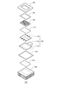
- FIG. 3 is a perspective view schematically showing the reaction unit 100.
- FIG. 4 is an exploded perspective view of the reaction unit 100.
- the reaction unit 100 mainly includes a holding unit 102, a holding unit base 104, a temperature control unit 106, a heat radiating unit 108, and heat conductive members 110 and 112.
- the holding portion 102 is a flat plate-shaped member that holds the reaction vessel 20. On one main surface of the holding portion 102, a hole for accommodating the convex portion on the back surface side of the reaction vessel 20 is provided. The reaction vessel 20 is placed on one of the main surfaces of the holding portion 102.
- the holding portion 102 is made of a metal having high thermal conductivity such as aluminum.
- the holding portion base 104 is a heat insulating member that suppresses heat dissipation from the holding portion 102.
- the holding portion base 104 is installed on the holding portion 102 via the upper packing 114.
- the holding portion base 104 has a frame shape and covers the periphery of the holding portion 102.
- the holding portion 102 is exposed at the opening of the holding portion base 104.
- the temperature control unit 106 heats and cools the holding unit 102 to adjust the temperature of the reaction solution in the reaction vessel 20.
- the temperature control unit 106 is arranged below the holding unit 102 in the vertical direction.
- the temperature control unit 106 has a thermoelectric element plate 116 and a substrate 118.
- the thermoelectric element plate 116 has a thermoelectric element and a temperature sensor.
- the thermoelectric element is, for example, a Perche element.
- the temperature sensor is, for example, a thermistor.
- the thermoelectric element heats and cools the holding portion 102.
- the temperature sensor detects the temperature of the holding unit 102 that is heated and cooled by the thermoelectric element.
- the thermoelectric element plate 116 is mounted on the substrate 118.
- the substrate 118 has a connector-shaped external connection terminal 118a.
- a control unit 24 and a power supply (not shown) are connected to the external connection terminal 118a.
- the temperature control unit 106 is controlled by the control unit 24. Specifically, the control signal from the control unit 24 is transmitted to the thermoelectric element of the thermoelectric element plate 116 via the substrate 118. Further, the output signal of the temperature sensor of the thermoelectric element plate 116 is transmitted to the control unit 24 via the substrate 118.
- the thermoelectric element heats and cools the holding unit 102 based on the instruction from the control unit 24. Further, the control unit 24 controls heating and cooling by the thermoelectric element based on the output value of the temperature sensor.
- the heat dissipation unit 108 is a member that dissipates heat from the thermoelectric element plate 116.
- the heat radiating unit 108 is, for example, a heat sink having a plurality of heat radiating fins.
- the heat radiating unit 108 is arranged vertically below the temperature control unit 106, and is connected to the temperature control unit 106 via the lower packing 134.
- the heat conduction member 110 is provided between the holding unit 102 and the temperature control unit 106, and mediates heat transfer between the two.
- the heat conduction member 112 is provided between the temperature control unit 106 and the heat dissipation unit 108, and mediates heat transfer between the two.
- the heat radiating section 108, the heat conductive member 112, the lower packing 134, the temperature control section 106, the heat conductive member 110, the holding section 102, the upper packing 114, and the holding section base 104 are laminated in this order from the bottom.
- the obtained laminate is fixed by the fixing member 136a and the fixing member 136b.
- the control unit 24 rotates the rotating unit 31 so that the light from the light source 30 is input to the first filter unit 32.
- the control unit 24 controls the temperature control unit 106 to amplify the target nucleic acid in the reaction solution.
- the control unit 24 of the present embodiment performs an isothermal nucleic acid amplification reaction.
- the isothermal nucleic acid amplification reaction is a nucleic acid amplification reaction that does not involve thermal denaturation of double-stranded DNA, that is, does not involve single-strandization of DNA due to temperature changes.
- Isothermal nucleic acid amplification reaction or isothermal nucleic acid amplification method includes RPA (Recombinase Primerase Amplification) method, LAMP (Loop-Mediated Isothermal Amplification) method, SDA (Strand Displacement Amplification) method, RCA (Rolling circle amplification) method, SMAP (Smart Amplification) method. ) Method and ICAN (Isothermal and Chimeric primer-initiated Amplification of Nucleic acids) method and the like are exemplified.
- the control unit 24 of the present embodiment implements the RPA method as an example.
- an oligonucleotide primer, a recombinase, a DNA polymerase, etc. having a sequence complementary to the target nucleic acid are added to the reaction solution, and the reaction solution is heated to a set temperature to proceed with the amplification reaction.
- the recombinase binds to the oligonucleotide primer to form a complex, and this complex binds to the double-stranded DNA constituting the target nucleic acid.
- the amplification reaction of the target nucleic acid proceeds.
- the amplification reaction proceeds at an isothermal temperature.
- the set temperature at the time of the amplification reaction is determined according to the type of enzyme used, and is, for example, 37 ° C to 42 ° C. In this embodiment, the set temperature is 40 ° C. as an example.
- the isothermal nucleic acid amplification method of the present embodiment includes detecting the target nucleic acid based on the labeling intensity of the reaction solution.
- a labeling substance for detecting the target nucleic acid is added to the reaction solution.
- a fluorescently labeled probe is used as an example of a labeling substance.
- the fluorescently labeled probe is specifically hybridized to the target nucleic acid in a state where the generation of fluorescent L1 from the fluorescent substance is suppressed by the quencher present on the probe. After that, when the fluorescently labeled probe is decomposed in the process of amplifying the target nucleic acid, the fluorescent substance is released from the probe and the suppression by the quencher is released.
- the reaction liquid is irradiated with the excitation light from the light source 30 in this state, the fluorescent substance is excited to emit fluorescence L1.
- the generated fluorescence L1 is incident on the camera 35 via the Fresnel lens 26, the reflecting mirror 25, the dichroic mirror 72, and the second optical filter 73.
- the control unit 24 can detect the fluorescence L1 in real time.
- the reaction solution contains the target nucleic acid
- the target nucleic acid is amplified in the reaction vessel 20, and the fluorescence intensity increases accordingly.
- the reaction solution does not contain the target nucleic acid
- the target nucleic acid is not amplified in the reaction vessel 20, and the fluorescence intensity is not detected or even if it is detected, it does not increase. Therefore, it is possible to detect and quantify the presence or absence of the target nucleic acid by measuring the change in the fluorescence intensity of the reaction solution.
- the second filter unit 33 is used.
- control unit 24 of the present embodiment controls the temperature control unit 106 so as to change the temperature of the reaction solution in a predetermined temperature cycle.
- the control unit 24 controls the thermoelectric element so that the temperature of the reaction solution reciprocates between a predetermined upper limit temperature and a predetermined lower limit temperature. Convection can be generated in the reaction solution by changing the temperature of the reaction solution in a predetermined temperature cycle.
- the temperature of the reaction solution does not change substantially, so that convection does not occur in the reaction solution and it is difficult to stir. Therefore, unreacted enzymes and substrates are likely to be unevenly distributed in the reaction solution.
- by performing a convection generation treatment that causes convection in the reaction solution unreacted enzymes and substrates in the reaction solution can be dispersed to further promote the amplification reaction of the target nucleic acid.
- the upper limit temperature, lower limit temperature and number of cycles of the temperature cycle can be appropriately set based on experiments and simulations by the designer.
- the upper limit temperature is preferably the set temperature of the nucleic acid amplification reaction. This makes it possible to suppress the inactivation of the enzyme used for nucleic acid amplification.
- the upper limit temperature is 40 ° C.
- the lower limit temperature is, for example, 30 ° C. or lower, preferably 20 ° C. or lower, and more preferably 10 ° C.
- the temperature range of the temperature cycle is set to a temperature range in which thermal denaturation of double-stranded DNA does not occur.
- the number of cycles is one or more.
- the temperature cycle means a combination of a temperature decrease and a temperature increase. Therefore, control in which the number of cycles is set to a plurality and the upper limit temperature and the lower limit temperature in each cycle are different for each cycle is also included in the convection generation process of the present embodiment.
- the timing of causing convection includes after the amplification reaction of the target nucleic acid contained in the reaction solution is stabilized and before the amplification reaction of the target nucleic acid contained in the reaction solution is stabilized.
- the “stabilization” is either (i) when the change in labeling intensity exceeds the turning point, or (ii) when the amount of change in labeling intensity per unit time falls below the threshold value.
- the threshold value of the amount of change can be appropriately set based on experiments and simulations by the designer.
- "before stabilization” is set before the temperature of the reaction solution reaches the set temperature of the amplification reaction after the reaction vessel 20 containing the reaction solution is installed in the holding portion 102, and before the temperature of the reaction solution reaches the set temperature of the amplification reaction. After reaching the temperature and including.
- "before stabilization” is after the temperature of the reaction solution reaches the set temperature of the amplification reaction.
- the temperature of the reaction solution has reached the set temperature of the amplification reaction based on the temperature detected by the temperature sensor of the temperature control unit 106. For example, when the detection temperature of the temperature sensor reaches the set temperature, it is determined that the temperature of the reaction solution has reached the set temperature. That is, the temperature of the holding portion 102 is regarded as the temperature of the reaction solution. Further, in the following description, for convenience, the time when the reaction solution reaches the set temperature is defined as the start of the isothermal nucleic acid amplification reaction.
- Example 1 is a case where convection is generated after the amplification reaction of the target nucleic acid is stabilized
- Example 2 is a case where convection is generated before the amplification reaction of the target nucleic acid is stabilized.
- FIG. 5A is a diagram showing a change in fluorescence intensity in Example 1.
- FIG. 5B is a diagram showing a change in fluorescence intensity in Example 2.
- the horizontal axis is the elapsed time (s) and the vertical axis is the fluorescence intensity (au).
- the result of the negative control is shown by a dotted line
- the result of the embodiment is shown by a solid line.
- Example 1 experiments were conducted using the TwistAmp (registered trademark) exo isothermal nucleic acid amplification reagent kit (manufactured by Twist Dx). Specifically, the positive control DNA attached to the kit was used as the target nucleic acid. In addition, the positive control primer / probe mix attached to the kit was used as the primer and the fluorescently labeled probe.
- TwistAmp registered trademark
- Twist Dx the positive control DNA attached to the kit was used as the target nucleic acid.
- the positive control primer / probe mix attached to the kit was used as the primer and the fluorescently labeled probe.
- Example 1 the convection generation process was carried out after the amount of change in the labeling intensity per unit time fell below the threshold value and the amplification reaction was stabilized (time zone A in FIG. 5 (A)).
- the convection generation process was started when 20 minutes had passed since the reaction solution reached the set temperature of 40 ° C.
- the fluorescence intensity before starting the convection generation process was about 3353.
- the temperature of the reaction solution is lowered from 40 ° C. to 10 ° C. and maintained for 5 seconds, then the temperature of the reaction solution is raised from 10 ° C. to 40 ° C. and maintained for 5 seconds, and this is set as one cycle for 10 cycles. bottom.
- the time required for the convection generation process is, for example, 5 minutes or less.
- the isothermal nucleic acid amplification reaction was carried out for 30 minutes excluding the time required for the convection generation process.
- the fluorescence intensity at the end of the isothermal nucleic acid amplification treatment was measured and found to be about 4373.
- the same convection generation treatment as in Example 1 was carried out at the same timing, and the fluorescence intensity at the time when the isothermal nucleic acid amplification treatment was completed was measured. The result was about 1817.
- Example 2 after 4 minutes have passed from the start of the isothermal nucleic acid amplification reaction (time zone A in FIG. 5B), that is, after 4 minutes have passed since the reaction solution reached the set temperature of 40 ° C. Convection generation processing was carried out. The fluorescence intensity before starting the convection generation process was about 1810. The content of the convection generation process is the same as that of the first embodiment.
- the isothermal nucleic acid amplification reaction was carried out for 30 minutes excluding the time required for the convection generation treatment. The fluorescence intensity at the end of the isothermal nucleic acid amplification treatment was measured and found to be about 4343.
- the same convection generation treatment as in Example 2 was carried out at the same timing, and the fluorescence intensity at the time when the isothermal nucleic acid amplification treatment was completed was measured. The result was about 1817.
- Example 1 and Example 2 an increase in fluorescence intensity was observed after the convection generation treatment was carried out. Moreover, in Example 1 and Example 2, the final fluorescence intensity was about the same. Therefore, the nucleic acid amplification reaction can be further promoted by carrying out the convection generation treatment both after the stabilization of the nucleic acid amplification reaction and before the stabilization. As a result, the detection accuracy of the target nucleic acid can be improved.
- the convection generation treatment may be carried out both after the stabilization of the nucleic acid amplification reaction and before the stabilization.
- the amplification curve of the target nucleic acid can be obtained as shown in FIG. 5 (A).
- the target nucleic acid can be quantified by a known method.
- the convection generation treatment is carried out before the stabilization of the nucleic acid amplification reaction, the amplification curve cannot be obtained, but the fluorescence intensity can be increased earlier. Therefore, the presence or absence of the target nucleic acid can be detected in a shorter time.
- the nucleic acid amplification reaction may be stabilized when (iii) a predetermined time elapses after the temperature of the reaction solution reaches the set temperature of the amplification reaction.
- a predetermined time elapses after the temperature of the reaction solution reaches the set temperature of the amplification reaction.
- Example 2 the same isothermal nucleic acid amplification reaction as in Example 1 was carried out except that the lower limit temperature in the convection generation treatment was changed to 10 ° C, 20 ° C, and 30 ° C.
- the lower limit temperature in the convection generation treatment was changed to 10 ° C, 20 ° C, and 30 ° C.
- the final fluorescence intensity was about 4273.
- the lower limit temperature of 20 ° C. the final fluorescence intensity was about 3391.
- the lower limit temperature of 30 ° C. the final fluorescence intensity was about 3082.
- the fluorescence intensity of the negative control was about 1860.
- the isothermal nucleic acid amplification method according to the present embodiment is an isothermal nucleic acid amplification method that does not involve thermal denaturation of double-stranded DNA, and reacts by changing the temperature of the reaction solution in a predetermined temperature cycle. Includes creating convection in the liquid.
- the isothermal nucleic acid amplification device 1 according to the present embodiment is an isothermal nucleic acid amplification device 1 that performs an isothermal nucleic acid amplification reaction without thermal denaturation of double-stranded DNA, and holds a reaction vessel 20 for storing a reaction solution.
- the holding unit 102, the temperature adjusting unit 106 that heats and cools the holding unit 102 to adjust the temperature of the reaction solution, and the control unit 24 that controls the temperature adjusting unit 106 are provided.
- the control unit 24 controls the temperature control unit 106 so as to change the temperature of the reaction solution in a predetermined temperature cycle to cause convection in the reaction solution.
- the detection time of the target nucleic acid can be significantly shortened as compared with the temperature-changing nucleic acid amplification reaction such as the PCR method.
- the isothermal nucleic acid amplification reaction since the reaction proceeds at an isothermal temperature, convection is less likely to occur in the reaction solution, and the reaction solution is less likely to be agitated. Therefore, unreacted enzymes and substrates are unevenly distributed in the reaction solution, and it is difficult to completely cause an amplification reaction.
- microballs which are magnetic materials
- a method of stirring the reaction solution there is a method of adding microballs (microbeads), which are magnetic materials, to the reaction solution, swirling the microballs by magnetic force, and physically stirring the reaction solution.
- microballs microballs
- a dedicated device for turning the microball is required.
- the use of microballs causes contamination of the reaction solution, increased labor of workers, increased cost, increased environmental load when disposing of the reaction solution, and the like.
- the labeling strength changes greatly depending on the presence or absence of stirring of the reaction solution. Therefore, if the operator forgets to add the microballs, the reaction solution is not agitated and a state with low labeling strength can be obtained. Can lead to misjudgment.
- convection is performed by changing the temperature of the reaction solution in a predetermined temperature cycle before and / or after the stabilization of the nucleic acid amplification reaction. Is generated, thereby stirring the reaction solution. Therefore, the detection accuracy of the target nucleic acid can be improved more easily, reliably, and at low cost as compared with the case of using microballs. In addition, contamination of the reaction solution, increase in environmental load, and occurrence of erroneous determination can be suppressed.
- the isothermal nucleic acid amplification reaction and the isothermal nucleic acid amplification device 1 of the present embodiment generate convection after the amplification reaction of the target nucleic acid contained in the reaction solution is stabilized. Thereby, the amplification curve of the target nucleic acid can be obtained and the target nucleic acid can be quantified.
- the isothermal nucleic acid amplification reaction and the isothermal nucleic acid amplification device 1 of the present embodiment generate convection before the amplification reaction of the target nucleic acid contained in the reaction solution is stabilized. As a result, the time required for detecting the presence or absence of the target nucleic acid can be shortened.
- the reaction solution of the present embodiment contains a labeling substance for detecting the target nucleic acid.
- the isothermal nucleic acid amplification method and the isothermal nucleic acid amplification device 1 include detecting the target nucleic acid based on the labeling intensity of the reaction solution. Then, the stabilization of the amplification reaction is defined as either (i) when the change in labeling intensity exceeds the inflection point, or (ii) when the amount of change in labeling intensity per unit time falls below the threshold value. As a result, the execution timing of the convection generation process can be grasped more accurately.
- the stabilization of the amplification reaction may be performed when (iii) a predetermined time elapses after the temperature of the reaction solution reaches the set temperature of the amplification reaction.
- the control since the execution timing of the convection generation process can be grasped without detecting the fluorescence intensity, the control can be simplified.
- reaction solution is stored in the recess of the reaction vessel 20, but the reaction solution may be added to a slide glass or the like. Further, the structure of each part of the isothermal nucleic acid amplification device 1 is not limited to the above.
- the embodiment of the present disclosure has been described in detail above.
- the above-described embodiment merely shows a specific example in carrying out the present disclosure.
- the content of the embodiment does not limit the technical scope of the present disclosure, and many design changes such as modification, addition, and deletion of components are not made within the scope of the invention defined in the claims. Is possible.
- the new embodiment with the design change has the effects of the combined embodiment and the modification.
- the contents that can be changed in design are emphasized by adding notations such as "in the present embodiment” and "in the present embodiment”. Design changes are allowed even if there is no content. Any combination of the above components is also valid as an aspect of the present disclosure.
- the hatching attached to the cross section of the drawing does not limit the material of the object to which the hatching is attached.
- the present disclosure can be used for an isothermal nucleic acid amplification method and an isothermal nucleic acid amplification device.
- 1 isothermal nucleic acid amplification device, 20 reaction vessel, 24 control unit, 102 holding unit, 106 temperature control unit.
Landscapes
- Chemical & Material Sciences (AREA)
- Life Sciences & Earth Sciences (AREA)
- Organic Chemistry (AREA)
- Engineering & Computer Science (AREA)
- Health & Medical Sciences (AREA)
- Wood Science & Technology (AREA)
- Zoology (AREA)
- Bioinformatics & Cheminformatics (AREA)
- Biotechnology (AREA)
- Proteomics, Peptides & Aminoacids (AREA)
- Microbiology (AREA)
- Genetics & Genomics (AREA)
- Biochemistry (AREA)
- General Engineering & Computer Science (AREA)
- General Health & Medical Sciences (AREA)
- Physics & Mathematics (AREA)
- Chemical Kinetics & Catalysis (AREA)
- Analytical Chemistry (AREA)
- Biophysics (AREA)
- Immunology (AREA)
- Molecular Biology (AREA)
- Sustainable Development (AREA)
- Biomedical Technology (AREA)
- Medicinal Chemistry (AREA)
- Apparatus Associated With Microorganisms And Enzymes (AREA)
- Measuring Or Testing Involving Enzymes Or Micro-Organisms (AREA)
Priority Applications (1)
| Application Number | Priority Date | Filing Date | Title |
|---|---|---|---|
| JP2022509506A JPWO2021192965A1 (https=) | 2020-03-26 | 2021-03-08 |
Applications Claiming Priority (2)
| Application Number | Priority Date | Filing Date | Title |
|---|---|---|---|
| JP2020056732 | 2020-03-26 | ||
| JP2020-056732 | 2020-03-26 |
Publications (1)
| Publication Number | Publication Date |
|---|---|
| WO2021192965A1 true WO2021192965A1 (ja) | 2021-09-30 |
Family
ID=77891834
Family Applications (1)
| Application Number | Title | Priority Date | Filing Date |
|---|---|---|---|
| PCT/JP2021/009035 Ceased WO2021192965A1 (ja) | 2020-03-26 | 2021-03-08 | 等温核酸増幅方法および等温核酸増幅装置 |
Country Status (2)
| Country | Link |
|---|---|
| JP (1) | JPWO2021192965A1 (https=) |
| WO (1) | WO2021192965A1 (https=) |
Citations (5)
| Publication number | Priority date | Publication date | Assignee | Title |
|---|---|---|---|---|
| WO2004067726A2 (en) * | 2003-01-29 | 2004-08-12 | Keck Graduate Institute | Isothermal reactions for the amplification of oligonucleotides |
| JP2008510455A (ja) * | 2004-07-29 | 2008-04-10 | ルモラ・リミテッド | 試料中に存在するテンプレート核酸の量を決定するための方法 |
| US20080269066A1 (en) * | 2005-02-11 | 2008-10-30 | Gerd-Uwe Flechsig | Method and Array for the Replication and Analysis of Nucleic Acids |
| JP2010000004A (ja) * | 2008-06-18 | 2010-01-07 | Canon Inc | 反応容器用補助具及びそれを用いた反応方法 |
| JP2015526092A (ja) * | 2012-08-24 | 2015-09-10 | ライフ テクノロジーズ コーポレーション | 核酸ペアエンド配列決定のための方法、組成物、システム、装置、およびキット |
Family Cites Families (1)
| Publication number | Priority date | Publication date | Assignee | Title |
|---|---|---|---|---|
| GB0915664D0 (en) * | 2009-09-08 | 2009-10-07 | Enigma Diagnostics Ltd | Reaction method |
-
2021
- 2021-03-08 WO PCT/JP2021/009035 patent/WO2021192965A1/ja not_active Ceased
- 2021-03-08 JP JP2022509506A patent/JPWO2021192965A1/ja active Pending
Patent Citations (5)
| Publication number | Priority date | Publication date | Assignee | Title |
|---|---|---|---|---|
| WO2004067726A2 (en) * | 2003-01-29 | 2004-08-12 | Keck Graduate Institute | Isothermal reactions for the amplification of oligonucleotides |
| JP2008510455A (ja) * | 2004-07-29 | 2008-04-10 | ルモラ・リミテッド | 試料中に存在するテンプレート核酸の量を決定するための方法 |
| US20080269066A1 (en) * | 2005-02-11 | 2008-10-30 | Gerd-Uwe Flechsig | Method and Array for the Replication and Analysis of Nucleic Acids |
| JP2010000004A (ja) * | 2008-06-18 | 2010-01-07 | Canon Inc | 反応容器用補助具及びそれを用いた反応方法 |
| JP2015526092A (ja) * | 2012-08-24 | 2015-09-10 | ライフ テクノロジーズ コーポレーション | 核酸ペアエンド配列決定のための方法、組成物、システム、装置、およびキット |
Also Published As
| Publication number | Publication date |
|---|---|
| JPWO2021192965A1 (https=) | 2021-09-30 |
Similar Documents
| Publication | Publication Date | Title |
|---|---|---|
| US20250161948A1 (en) | Portable devices and methods for analyzing samples | |
| JP4633730B2 (ja) | 可動検出モジュールを用いる蛍光検出システム及び方法 | |
| US20240288456A1 (en) | Portable Devices and Methods for Analyzing Samples | |
| US8987685B2 (en) | Optical system for multiple reactions | |
| CN102533539B (zh) | 用于液体样品的自动热处理的仪器和方法 | |
| JP4969650B2 (ja) | 遺伝子検出判定装置および遺伝子検出判定方法並びに遺伝子反応装置 | |
| JP7483745B2 (ja) | 多機能性分析デバイス | |
| JP6754420B2 (ja) | 対流pcr装置 | |
| JP4854334B2 (ja) | 核酸増幅生成物のリアルタイム検出装置 | |
| CA2562517A1 (en) | System for rapid nucleic acid amplification and detection | |
| US20120149005A1 (en) | Reaction treatment device and reaction treatment method | |
| CN103703118A (zh) | 核酸检查装置 | |
| KR101335204B1 (ko) | 증폭 장치, 검출 장치 | |
| WO2021192965A1 (ja) | 等温核酸増幅方法および等温核酸増幅装置 | |
| JP2009171921A (ja) | 蛍光増幅核酸の検出装置及び検出方法 | |
| TW201339308A (zh) | 核酸序列擴增檢測裝置 | |
| CN204325370U (zh) | 手持式即时检测装置 | |
| Pierik et al. | Real time quantitative amplification detection on a microarray: towards high multiplex quantitative PCR | |
| JP2016185103A (ja) | 核酸増幅装置 | |
| JP2010022315A (ja) | 核酸量検出装置及び核酸量検出方法 | |
| CN105733940B (zh) | 手持式即时检测装置 | |
| CN105733940A (zh) | 手持式即时检测装置 | |
| JP2018046764A (ja) | 核酸増幅反応容器、核酸増幅反応装置、および核酸増幅反応方法 | |
| JP2018033414A (ja) | 核酸増幅反応容器、核酸増幅反応装置、および核酸増幅反応方法 |
Legal Events
| Date | Code | Title | Description |
|---|---|---|---|
| 121 | Ep: the epo has been informed by wipo that ep was designated in this application |
Ref document number: 21776634 Country of ref document: EP Kind code of ref document: A1 |
|
| ENP | Entry into the national phase |
Ref document number: 2022509506 Country of ref document: JP Kind code of ref document: A |
|
| NENP | Non-entry into the national phase |
Ref country code: DE |
|
| 122 | Ep: pct application non-entry in european phase |
Ref document number: 21776634 Country of ref document: EP Kind code of ref document: A1 |