WO2021192965A1 - 等温核酸増幅方法および等温核酸増幅装置 - Google Patents
等温核酸増幅方法および等温核酸増幅装置 Download PDFInfo
- Publication number
- WO2021192965A1 WO2021192965A1 PCT/JP2021/009035 JP2021009035W WO2021192965A1 WO 2021192965 A1 WO2021192965 A1 WO 2021192965A1 JP 2021009035 W JP2021009035 W JP 2021009035W WO 2021192965 A1 WO2021192965 A1 WO 2021192965A1
- Authority
- WO
- WIPO (PCT)
- Prior art keywords
- nucleic acid
- reaction solution
- acid amplification
- temperature
- reaction
- Prior art date
Links
Images


Classifications
-
- C—CHEMISTRY; METALLURGY
- C12—BIOCHEMISTRY; BEER; SPIRITS; WINE; VINEGAR; MICROBIOLOGY; ENZYMOLOGY; MUTATION OR GENETIC ENGINEERING
- C12M—APPARATUS FOR ENZYMOLOGY OR MICROBIOLOGY; APPARATUS FOR CULTURING MICROORGANISMS FOR PRODUCING BIOMASS, FOR GROWING CELLS OR FOR OBTAINING FERMENTATION OR METABOLIC PRODUCTS, i.e. BIOREACTORS OR FERMENTERS
- C12M1/00—Apparatus for enzymology or microbiology
-
- C—CHEMISTRY; METALLURGY
- C12—BIOCHEMISTRY; BEER; SPIRITS; WINE; VINEGAR; MICROBIOLOGY; ENZYMOLOGY; MUTATION OR GENETIC ENGINEERING
- C12Q—MEASURING OR TESTING PROCESSES INVOLVING ENZYMES, NUCLEIC ACIDS OR MICROORGANISMS; COMPOSITIONS OR TEST PAPERS THEREFOR; PROCESSES OF PREPARING SUCH COMPOSITIONS; CONDITION-RESPONSIVE CONTROL IN MICROBIOLOGICAL OR ENZYMOLOGICAL PROCESSES
- C12Q1/00—Measuring or testing processes involving enzymes, nucleic acids or microorganisms; Compositions therefor; Processes of preparing such compositions
- C12Q1/68—Measuring or testing processes involving enzymes, nucleic acids or microorganisms; Compositions therefor; Processes of preparing such compositions involving nucleic acids
- C12Q1/6844—Nucleic acid amplification reactions
- C12Q1/6851—Quantitative amplification
Definitions
- the present disclosure relates to an isothermal nucleic acid amplification method and an isothermal nucleic acid amplification device.
- a nucleic acid amplification method in which a nucleic acid such as DNA (Deoxyribonucleic Acid: deoxyribonucleic acid) is allowed to undergo a polymerase chain reaction (PCR) to amplify the nucleic acid.
- PCR polymerase chain reaction
- a nucleic acid detection unit is provided in addition to a nucleic acid amplification mechanism, and the amplified nucleic acid is detected in real time.
- isothermal nucleic acid amplification methods capable of amplifying nucleic acids under isothermal conditions, such as the RPA (Recombinase Plymerase Amplification) method and the LAMP (Loop-Mediated Isothermal Amplification) method, have been proposed (for example, patent documents). 1).
- RPA Recombinase Plymerase Amplification
- LAMP Loop-Mediated Isothermal Amplification
- the isothermal nucleic acid amplification method does not require a temperature cycle to amplify the nucleic acid. Therefore, the reaction time can be shortened as compared with a method involving a temperature cycle such as the PCR method. This makes it possible to detect the target nucleic acid in a shorter time or at a lower cost. On the other hand, improvement in detection accuracy of the target nucleic acid is always required. As a result of diligent studies, the present inventor has found that the conventional isothermal nucleic acid amplification method has room for improving the detection accuracy of the target nucleic acid.
- the present disclosure has been made in view of such a situation, and one of the purposes thereof is to provide a technique for improving the detection accuracy when detecting a target nucleic acid by using an isothermal nucleic acid amplification method.
- one aspect of the present disclosure is an isothermal nucleic acid amplification method that does not involve thermal denaturation of double-stranded DNA. This method involves changing the temperature of the reaction solution in a predetermined temperature cycle to cause convection in the reaction solution.
- Another aspect of the present disclosure is an isothermal nucleic acid amplification device that performs an isothermal nucleic acid amplification reaction without thermal denaturation of double-stranded DNA.
- This device includes a holding unit that holds a reaction vessel that stores the reaction solution, a temperature control unit that heats and cools the holding unit to control the temperature of the reaction solution, and a control unit that controls the temperature control unit. Be prepared.
- the control unit controls the temperature control unit so as to change the temperature of the reaction solution in a predetermined temperature cycle to cause convection in the reaction solution.
- FIG. 5A is a diagram showing a change in fluorescence intensity in Example 1.
- FIG. 5B is a diagram showing a change in fluorescence intensity in Example 2.
- FIG. 1 is a side view schematically showing an isothermal nucleic acid amplification device according to the embodiment.
- FIG. 2 is a plan view schematically showing an isothermal nucleic acid amplification device according to the embodiment.
- FIGS. 1 and 2 a state in which the inside of the isothermal nucleic acid amplification device 1 is seen through is shown.
- a part of the structure is drawn in a cross-sectional view.
- the isothermal nucleic acid amplification device 1 controls the temperature of a reaction solution containing a nucleic acid such as DNA and a labeling substance to amplify the nucleic acid, and measures the amplified nucleic acid according to the type of the labeling substance. It is a device that can detect.
- the isothermal nucleic acid amplification device 1 of the present embodiment uses a fluorescent substance such as a fluorescently labeled probe or a DNA intercalator as an example of the labeling substance.
- the isothermal nucleic acid amplification device 1 includes a case 15 and a cover 16 attached to the front of the case 15.
- the reaction container 20, the container cover 22, the reaction unit 100, the control unit 24, the light source 30, the rotating unit 31, the first filter unit 32, the second filter unit 33, the motor 34, and the camera 35 are housed in the case 15. ..
- the cover 16 is installed in the case 15 so as to be movable back and forth.
- the cover 16 is housed inside the case 15 when it is moved rearward.
- the user of the isothermal nucleic acid amplification device 1 can replace the reaction vessel 20 in the case 15.
- FIG. 1 shows a state in which the cover 16 is moved forward.
- a light-shielding member (not shown) is attached between the case 15 and the cover 16.
- a reflector 25 and a Fresnel lens 26 are installed inside the cover 16.
- an operation panel that also serves as an operation unit for transmitting a control signal to the control unit 24 and a display unit that displays imaging information of the camera 35, detection results of the control unit 24, and the like are provided.
- the operation panel may be provided on the case 15, or may be separate from the case 15 and the cover 16.
- the reaction vessel 20 has a plurality of recesses arranged in a matrix.
- the number of depressions is not particularly limited.
- Each recess contains a reaction solution for which the presence or absence of the target nucleic acid and the amount of the target nucleic acid are to be detected.
- a fluorescent substance as a labeling substance is added to the reaction solution.
- the reaction vessel 20 is made of, for example, a thin plate made of resin.
- the reaction unit 100 supports the reaction vessel 20 and adjusts the temperature of the reaction vessel 20 based on the instruction of the control unit 24. The structure of the reaction unit 100 and the temperature control by the control unit 24 will be described in detail later.
- the container cover 22 is a member that covers the reaction container 20.
- the container cover 22 can prevent the reaction solution from evaporating when the reaction container 20 is heated.
- a light-transmitting film or the like is used for the container cover 22 so that the excitation light for exciting the fluorescent substance in the reaction solution and the fluorescence emitted from the reaction solution are transmitted.
- the reflecting mirror 25 reflects the excitation light from the first filter unit 32 and the second filter unit 33 toward the Fresnel lens 26. Further, the reflecting mirror 25 reflects the fluorescence from the reaction solution toward the camera 35.
- the Fresnel lens 26 converges the excitation light reflected by the reflector 25 so as to be parallel to the optical axis of the Fresnel lens 26 and transmits it.
- the light source 30 is installed on the inner side surface (-Y side side surface) of the case 15.
- the light source 30 is, for example, a halogen lamp, and irradiates light including excitation light.
- the rotating unit 31 is a so-called turret type rotating device.
- the first filter unit 32 and the second filter unit 33 are mounted on the rotating unit 31.
- the first filter unit 32 and the second filter unit 33 are used when observing the fluorescence from the reaction solution.
- the rotating portion 31 has a first rotating plate 60, a second rotating plate 61, and a rotating shaft 62.
- the first rotating plate 60 is arranged on the camera 35 side, and the second rotating plate 61 is arranged on the reflecting mirror 25 side.
- the first rotating plate 60 and the second rotating plate 61 extend in parallel with each other.
- the first filter unit 32 and the second filter unit 33 are mounted between the first rotating plate 60 and the second rotating plate 61.
- the rotating portion 31 can be equipped with, for example, a maximum of six filter portions between the first rotating plate 60 and the second rotating plate 61.
- the first rotating plate 60 is provided with a window through which fluorescence passes at a position where the first filter unit 32 and the second filter unit 33 are mounted.
- the second rotating plate 61 is provided with a window for passing excitation light and fluorescence at a position where the first filter unit 32 and the second filter unit 33 are mounted.
- One end of the rotating shaft 62 is connected to the motor 34, and the rotating shaft 62 is rotated by driving the motor 34. Further, the first rotating plate 60 and the second rotating plate 61 are connected to the rotating shaft 62. The rotating shaft 62 rotates the first rotating plate 60 and the second rotating plate 61, and the first filter unit 32 and the second filter unit 33 by its own rotation.
- the second filter unit 33 is mounted at a position displaced by 180 degrees around the rotation axis 62 from the position where the first filter unit 32 is provided.
- the rotating unit 31 moves either the first filter unit 32 or the second filter unit 33 to a position facing the light source 30.
- the "position facing the light source 30" means a position where the optical axis of the light source 30 and the optical filter of the filter unit intersect.
- FIG. 2 shows a state in which the first filter unit 32 is at a position facing the light source 30.
- the first filter unit 32 is used when observing the fluorescence L1.
- the first filter unit 32 includes a box-shaped filter cube 70, a first optical filter 71, a second optical filter 73, and a dichroic mirror 72.
- the first optical filter 71, the second optical filter 73, and the dichroic mirror 72 are attached to the filter cube 70.
- the first optical filter 71 is a bandpass filter that transmits the excitation light that excites the reaction solution among the light from the light source 30.
- the first optical filter 71 is arranged so as to intersect the optical axis of the light source 30 with the first filter unit 32 at a position facing the light source 30.
- the dichroic mirror 72 reflects the excitation light transmitted through the first optical filter 71 toward the reflector 25 in order to irradiate the reaction solution with the excitation light.
- the excitation light reflected by the dichroic mirror 72 travels from the window of the second rotating plate 61 toward the reflecting mirror 25.
- the excitation light that reaches the reflector 25 is reflected by the reflector 25, passes through the Fresnel lens 26, and is irradiated to the reaction vessel 20.
- the reaction vessel 20 is irradiated with excitation light, the reaction solution is excited and fluorescence L1 is emitted.
- the fluorescent L1 passes through the Fresnel lens 26, is reflected by the reflecting mirror 25, and travels from the window of the second rotating plate 61 toward the dichroic mirror 72.
- the dichroic mirror 72 transmits the fluorescence L1.
- the second optical filter 73 is a bandpass filter that selectively transmits the fluorescence L1 transmitted through the dichroic mirror 72.
- the second optical filter 73 is fitted in the window of the first rotating plate 60.
- the fluorescence L1 transmitted through the second optical filter 73 is incident on the camera 35.
- the second filter unit 33 is used when observing the fluorescence L2.
- the second filter unit 33 includes a box-shaped filter cube 80, a third optical filter 81, a fourth optical filter 83, and a dichroic mirror 82.
- the third optical filter 81, the fourth optical filter 83, and the dichroic mirror 82 are attached to the filter cube 80.
- the third optical filter 81 is a bandpass filter that transmits the excitation light that excites the reaction solution among the light from the light source 30.
- the third optical filter 81 is arranged so as to intersect the optical axis of the light source 30 with the second filter unit 33 at a position facing the light source 30.
- the dichroic mirror 82 reflects the excitation light transmitted through the third optical filter 81 toward the reflector 25 in order to irradiate the reaction solution with the excitation light.
- the excitation light reflected by the dichroic mirror 82 travels from the window of the second rotating plate 61 toward the reflecting mirror 25.
- the excitation light that reaches the reflector 25 is reflected by the reflector 25, passes through the Fresnel lens 26, and is irradiated to the reaction vessel 20.
- the reaction vessel 20 is irradiated with excitation light, the reaction solution is excited and fluorescence L2 is emitted.
- the fluorescent L2 passes through the Fresnel lens 26, is reflected by the reflecting mirror 25, and travels toward the dichroic mirror 82 from the window of the second rotating plate 61.
- the dichroic mirror 82 transmits the fluorescence L2.
- the fourth optical filter 83 is a bandpass filter that selectively transmits the fluorescent L2 transmitted through the dichroic mirror 82.
- the fourth optical filter 83 is fitted in the window of the first rotating plate 60.
- the fluorescent L2 transmitted through the fourth optical filter 83 is incident on the camera 35.
- the motor 34 rotates the rotating shaft 62.
- the motor 34 is, for example, a stepping motor.
- the camera 35 receives the fluorescence L1 and L2 and takes a picture.
- the camera 35 sends the acquired image information to the control unit 24.
- the image information is transmitted to and displayed on the operation panel via the control unit 24 or directly from the camera 35.
- the control unit 24 controls the operation of each unit of the isothermal nucleic acid amplification device 1. Specifically, the control unit 24 controls the temperature control of the reaction vessel 20 by the reaction unit 100. Further, the control unit 24 controls the turning on and off of the light source 30 and the rotation of the motor 34. Further, the control unit 24 detects the labeling intensity of the reaction solution by a known method based on the image information obtained from the camera 35. For example, the control unit 24 can calculate the marking intensity based on the brightness value of each pixel in the acquired image information. The calculated marker strength is displayed on the operation panel or the like. As a result, the user of the isothermal nucleic acid amplification device 1 can grasp the presence / absence and amount of the target nucleic acid in the reaction solution.
- the control unit 24 is realized by elements and circuits such as a computer CPU and memory as a hardware configuration, and is realized by a computer program or the like as a software configuration, but in FIG. 1, it is realized by their cooperation. It is drawn as a functional block. It is well understood by those skilled in the art that this functional block can be realized in various ways by a combination of hardware and software.
- the control unit 24 may be provided outside the case 15.
- FIG. 3 is a perspective view schematically showing the reaction unit 100.
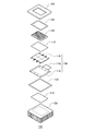
- FIG. 4 is an exploded perspective view of the reaction unit 100.
- the reaction unit 100 mainly includes a holding unit 102, a holding unit base 104, a temperature control unit 106, a heat radiating unit 108, and heat conductive members 110 and 112.
- the holding portion 102 is a flat plate-shaped member that holds the reaction vessel 20. On one main surface of the holding portion 102, a hole for accommodating the convex portion on the back surface side of the reaction vessel 20 is provided. The reaction vessel 20 is placed on one of the main surfaces of the holding portion 102.
- the holding portion 102 is made of a metal having high thermal conductivity such as aluminum.
- the holding portion base 104 is a heat insulating member that suppresses heat dissipation from the holding portion 102.
- the holding portion base 104 is installed on the holding portion 102 via the upper packing 114.
- the holding portion base 104 has a frame shape and covers the periphery of the holding portion 102.
- the holding portion 102 is exposed at the opening of the holding portion base 104.
- the temperature control unit 106 heats and cools the holding unit 102 to adjust the temperature of the reaction solution in the reaction vessel 20.
- the temperature control unit 106 is arranged below the holding unit 102 in the vertical direction.
- the temperature control unit 106 has a thermoelectric element plate 116 and a substrate 118.
- the thermoelectric element plate 116 has a thermoelectric element and a temperature sensor.
- the thermoelectric element is, for example, a Perche element.
- the temperature sensor is, for example, a thermistor.
- the thermoelectric element heats and cools the holding portion 102.
- the temperature sensor detects the temperature of the holding unit 102 that is heated and cooled by the thermoelectric element.
- the thermoelectric element plate 116 is mounted on the substrate 118.
- the substrate 118 has a connector-shaped external connection terminal 118a.
- a control unit 24 and a power supply (not shown) are connected to the external connection terminal 118a.
- the temperature control unit 106 is controlled by the control unit 24. Specifically, the control signal from the control unit 24 is transmitted to the thermoelectric element of the thermoelectric element plate 116 via the substrate 118. Further, the output signal of the temperature sensor of the thermoelectric element plate 116 is transmitted to the control unit 24 via the substrate 118.
- the thermoelectric element heats and cools the holding unit 102 based on the instruction from the control unit 24. Further, the control unit 24 controls heating and cooling by the thermoelectric element based on the output value of the temperature sensor.
- the heat dissipation unit 108 is a member that dissipates heat from the thermoelectric element plate 116.
- the heat radiating unit 108 is, for example, a heat sink having a plurality of heat radiating fins.
- the heat radiating unit 108 is arranged vertically below the temperature control unit 106, and is connected to the temperature control unit 106 via the lower packing 134.
- the heat conduction member 110 is provided between the holding unit 102 and the temperature control unit 106, and mediates heat transfer between the two.
- the heat conduction member 112 is provided between the temperature control unit 106 and the heat dissipation unit 108, and mediates heat transfer between the two.
- the heat radiating section 108, the heat conductive member 112, the lower packing 134, the temperature control section 106, the heat conductive member 110, the holding section 102, the upper packing 114, and the holding section base 104 are laminated in this order from the bottom.
- the obtained laminate is fixed by the fixing member 136a and the fixing member 136b.
- the control unit 24 rotates the rotating unit 31 so that the light from the light source 30 is input to the first filter unit 32.
- the control unit 24 controls the temperature control unit 106 to amplify the target nucleic acid in the reaction solution.
- the control unit 24 of the present embodiment performs an isothermal nucleic acid amplification reaction.
- the isothermal nucleic acid amplification reaction is a nucleic acid amplification reaction that does not involve thermal denaturation of double-stranded DNA, that is, does not involve single-strandization of DNA due to temperature changes.
- Isothermal nucleic acid amplification reaction or isothermal nucleic acid amplification method includes RPA (Recombinase Primerase Amplification) method, LAMP (Loop-Mediated Isothermal Amplification) method, SDA (Strand Displacement Amplification) method, RCA (Rolling circle amplification) method, SMAP (Smart Amplification) method. ) Method and ICAN (Isothermal and Chimeric primer-initiated Amplification of Nucleic acids) method and the like are exemplified.
- the control unit 24 of the present embodiment implements the RPA method as an example.
- an oligonucleotide primer, a recombinase, a DNA polymerase, etc. having a sequence complementary to the target nucleic acid are added to the reaction solution, and the reaction solution is heated to a set temperature to proceed with the amplification reaction.
- the recombinase binds to the oligonucleotide primer to form a complex, and this complex binds to the double-stranded DNA constituting the target nucleic acid.
- the amplification reaction of the target nucleic acid proceeds.
- the amplification reaction proceeds at an isothermal temperature.
- the set temperature at the time of the amplification reaction is determined according to the type of enzyme used, and is, for example, 37 ° C to 42 ° C. In this embodiment, the set temperature is 40 ° C. as an example.
- the isothermal nucleic acid amplification method of the present embodiment includes detecting the target nucleic acid based on the labeling intensity of the reaction solution.
- a labeling substance for detecting the target nucleic acid is added to the reaction solution.
- a fluorescently labeled probe is used as an example of a labeling substance.
- the fluorescently labeled probe is specifically hybridized to the target nucleic acid in a state where the generation of fluorescent L1 from the fluorescent substance is suppressed by the quencher present on the probe. After that, when the fluorescently labeled probe is decomposed in the process of amplifying the target nucleic acid, the fluorescent substance is released from the probe and the suppression by the quencher is released.
- the reaction liquid is irradiated with the excitation light from the light source 30 in this state, the fluorescent substance is excited to emit fluorescence L1.
- the generated fluorescence L1 is incident on the camera 35 via the Fresnel lens 26, the reflecting mirror 25, the dichroic mirror 72, and the second optical filter 73.
- the control unit 24 can detect the fluorescence L1 in real time.
- the reaction solution contains the target nucleic acid
- the target nucleic acid is amplified in the reaction vessel 20, and the fluorescence intensity increases accordingly.
- the reaction solution does not contain the target nucleic acid
- the target nucleic acid is not amplified in the reaction vessel 20, and the fluorescence intensity is not detected or even if it is detected, it does not increase. Therefore, it is possible to detect and quantify the presence or absence of the target nucleic acid by measuring the change in the fluorescence intensity of the reaction solution.
- the second filter unit 33 is used.
- control unit 24 of the present embodiment controls the temperature control unit 106 so as to change the temperature of the reaction solution in a predetermined temperature cycle.
- the control unit 24 controls the thermoelectric element so that the temperature of the reaction solution reciprocates between a predetermined upper limit temperature and a predetermined lower limit temperature. Convection can be generated in the reaction solution by changing the temperature of the reaction solution in a predetermined temperature cycle.
- the temperature of the reaction solution does not change substantially, so that convection does not occur in the reaction solution and it is difficult to stir. Therefore, unreacted enzymes and substrates are likely to be unevenly distributed in the reaction solution.
- by performing a convection generation treatment that causes convection in the reaction solution unreacted enzymes and substrates in the reaction solution can be dispersed to further promote the amplification reaction of the target nucleic acid.
- the upper limit temperature, lower limit temperature and number of cycles of the temperature cycle can be appropriately set based on experiments and simulations by the designer.
- the upper limit temperature is preferably the set temperature of the nucleic acid amplification reaction. This makes it possible to suppress the inactivation of the enzyme used for nucleic acid amplification.
- the upper limit temperature is 40 ° C.
- the lower limit temperature is, for example, 30 ° C. or lower, preferably 20 ° C. or lower, and more preferably 10 ° C.
- the temperature range of the temperature cycle is set to a temperature range in which thermal denaturation of double-stranded DNA does not occur.
- the number of cycles is one or more.
- the temperature cycle means a combination of a temperature decrease and a temperature increase. Therefore, control in which the number of cycles is set to a plurality and the upper limit temperature and the lower limit temperature in each cycle are different for each cycle is also included in the convection generation process of the present embodiment.
- the timing of causing convection includes after the amplification reaction of the target nucleic acid contained in the reaction solution is stabilized and before the amplification reaction of the target nucleic acid contained in the reaction solution is stabilized.
- the “stabilization” is either (i) when the change in labeling intensity exceeds the turning point, or (ii) when the amount of change in labeling intensity per unit time falls below the threshold value.
- the threshold value of the amount of change can be appropriately set based on experiments and simulations by the designer.
- "before stabilization” is set before the temperature of the reaction solution reaches the set temperature of the amplification reaction after the reaction vessel 20 containing the reaction solution is installed in the holding portion 102, and before the temperature of the reaction solution reaches the set temperature of the amplification reaction. After reaching the temperature and including.
- "before stabilization” is after the temperature of the reaction solution reaches the set temperature of the amplification reaction.
- the temperature of the reaction solution has reached the set temperature of the amplification reaction based on the temperature detected by the temperature sensor of the temperature control unit 106. For example, when the detection temperature of the temperature sensor reaches the set temperature, it is determined that the temperature of the reaction solution has reached the set temperature. That is, the temperature of the holding portion 102 is regarded as the temperature of the reaction solution. Further, in the following description, for convenience, the time when the reaction solution reaches the set temperature is defined as the start of the isothermal nucleic acid amplification reaction.
- Example 1 is a case where convection is generated after the amplification reaction of the target nucleic acid is stabilized
- Example 2 is a case where convection is generated before the amplification reaction of the target nucleic acid is stabilized.
- FIG. 5A is a diagram showing a change in fluorescence intensity in Example 1.
- FIG. 5B is a diagram showing a change in fluorescence intensity in Example 2.
- the horizontal axis is the elapsed time (s) and the vertical axis is the fluorescence intensity (au).
- the result of the negative control is shown by a dotted line
- the result of the embodiment is shown by a solid line.
- Example 1 experiments were conducted using the TwistAmp (registered trademark) exo isothermal nucleic acid amplification reagent kit (manufactured by Twist Dx). Specifically, the positive control DNA attached to the kit was used as the target nucleic acid. In addition, the positive control primer / probe mix attached to the kit was used as the primer and the fluorescently labeled probe.
- TwistAmp registered trademark
- Twist Dx the positive control DNA attached to the kit was used as the target nucleic acid.
- the positive control primer / probe mix attached to the kit was used as the primer and the fluorescently labeled probe.
- Example 1 the convection generation process was carried out after the amount of change in the labeling intensity per unit time fell below the threshold value and the amplification reaction was stabilized (time zone A in FIG. 5 (A)).
- the convection generation process was started when 20 minutes had passed since the reaction solution reached the set temperature of 40 ° C.
- the fluorescence intensity before starting the convection generation process was about 3353.
- the temperature of the reaction solution is lowered from 40 ° C. to 10 ° C. and maintained for 5 seconds, then the temperature of the reaction solution is raised from 10 ° C. to 40 ° C. and maintained for 5 seconds, and this is set as one cycle for 10 cycles. bottom.
- the time required for the convection generation process is, for example, 5 minutes or less.
- the isothermal nucleic acid amplification reaction was carried out for 30 minutes excluding the time required for the convection generation process.
- the fluorescence intensity at the end of the isothermal nucleic acid amplification treatment was measured and found to be about 4373.
- the same convection generation treatment as in Example 1 was carried out at the same timing, and the fluorescence intensity at the time when the isothermal nucleic acid amplification treatment was completed was measured. The result was about 1817.
- Example 2 after 4 minutes have passed from the start of the isothermal nucleic acid amplification reaction (time zone A in FIG. 5B), that is, after 4 minutes have passed since the reaction solution reached the set temperature of 40 ° C. Convection generation processing was carried out. The fluorescence intensity before starting the convection generation process was about 1810. The content of the convection generation process is the same as that of the first embodiment.
- the isothermal nucleic acid amplification reaction was carried out for 30 minutes excluding the time required for the convection generation treatment. The fluorescence intensity at the end of the isothermal nucleic acid amplification treatment was measured and found to be about 4343.
- the same convection generation treatment as in Example 2 was carried out at the same timing, and the fluorescence intensity at the time when the isothermal nucleic acid amplification treatment was completed was measured. The result was about 1817.
- Example 1 and Example 2 an increase in fluorescence intensity was observed after the convection generation treatment was carried out. Moreover, in Example 1 and Example 2, the final fluorescence intensity was about the same. Therefore, the nucleic acid amplification reaction can be further promoted by carrying out the convection generation treatment both after the stabilization of the nucleic acid amplification reaction and before the stabilization. As a result, the detection accuracy of the target nucleic acid can be improved.
- the convection generation treatment may be carried out both after the stabilization of the nucleic acid amplification reaction and before the stabilization.
- the amplification curve of the target nucleic acid can be obtained as shown in FIG. 5 (A).
- the target nucleic acid can be quantified by a known method.
- the convection generation treatment is carried out before the stabilization of the nucleic acid amplification reaction, the amplification curve cannot be obtained, but the fluorescence intensity can be increased earlier. Therefore, the presence or absence of the target nucleic acid can be detected in a shorter time.
- the nucleic acid amplification reaction may be stabilized when (iii) a predetermined time elapses after the temperature of the reaction solution reaches the set temperature of the amplification reaction.
- a predetermined time elapses after the temperature of the reaction solution reaches the set temperature of the amplification reaction.
- Example 2 the same isothermal nucleic acid amplification reaction as in Example 1 was carried out except that the lower limit temperature in the convection generation treatment was changed to 10 ° C, 20 ° C, and 30 ° C.
- the lower limit temperature in the convection generation treatment was changed to 10 ° C, 20 ° C, and 30 ° C.
- the final fluorescence intensity was about 4273.
- the lower limit temperature of 20 ° C. the final fluorescence intensity was about 3391.
- the lower limit temperature of 30 ° C. the final fluorescence intensity was about 3082.
- the fluorescence intensity of the negative control was about 1860.
- the isothermal nucleic acid amplification method according to the present embodiment is an isothermal nucleic acid amplification method that does not involve thermal denaturation of double-stranded DNA, and reacts by changing the temperature of the reaction solution in a predetermined temperature cycle. Includes creating convection in the liquid.
- the isothermal nucleic acid amplification device 1 according to the present embodiment is an isothermal nucleic acid amplification device 1 that performs an isothermal nucleic acid amplification reaction without thermal denaturation of double-stranded DNA, and holds a reaction vessel 20 for storing a reaction solution.
- the holding unit 102, the temperature adjusting unit 106 that heats and cools the holding unit 102 to adjust the temperature of the reaction solution, and the control unit 24 that controls the temperature adjusting unit 106 are provided.
- the control unit 24 controls the temperature control unit 106 so as to change the temperature of the reaction solution in a predetermined temperature cycle to cause convection in the reaction solution.
- the detection time of the target nucleic acid can be significantly shortened as compared with the temperature-changing nucleic acid amplification reaction such as the PCR method.
- the isothermal nucleic acid amplification reaction since the reaction proceeds at an isothermal temperature, convection is less likely to occur in the reaction solution, and the reaction solution is less likely to be agitated. Therefore, unreacted enzymes and substrates are unevenly distributed in the reaction solution, and it is difficult to completely cause an amplification reaction.
- microballs which are magnetic materials
- a method of stirring the reaction solution there is a method of adding microballs (microbeads), which are magnetic materials, to the reaction solution, swirling the microballs by magnetic force, and physically stirring the reaction solution.
- microballs microballs
- a dedicated device for turning the microball is required.
- the use of microballs causes contamination of the reaction solution, increased labor of workers, increased cost, increased environmental load when disposing of the reaction solution, and the like.
- the labeling strength changes greatly depending on the presence or absence of stirring of the reaction solution. Therefore, if the operator forgets to add the microballs, the reaction solution is not agitated and a state with low labeling strength can be obtained. Can lead to misjudgment.
- convection is performed by changing the temperature of the reaction solution in a predetermined temperature cycle before and / or after the stabilization of the nucleic acid amplification reaction. Is generated, thereby stirring the reaction solution. Therefore, the detection accuracy of the target nucleic acid can be improved more easily, reliably, and at low cost as compared with the case of using microballs. In addition, contamination of the reaction solution, increase in environmental load, and occurrence of erroneous determination can be suppressed.
- the isothermal nucleic acid amplification reaction and the isothermal nucleic acid amplification device 1 of the present embodiment generate convection after the amplification reaction of the target nucleic acid contained in the reaction solution is stabilized. Thereby, the amplification curve of the target nucleic acid can be obtained and the target nucleic acid can be quantified.
- the isothermal nucleic acid amplification reaction and the isothermal nucleic acid amplification device 1 of the present embodiment generate convection before the amplification reaction of the target nucleic acid contained in the reaction solution is stabilized. As a result, the time required for detecting the presence or absence of the target nucleic acid can be shortened.
- the reaction solution of the present embodiment contains a labeling substance for detecting the target nucleic acid.
- the isothermal nucleic acid amplification method and the isothermal nucleic acid amplification device 1 include detecting the target nucleic acid based on the labeling intensity of the reaction solution. Then, the stabilization of the amplification reaction is defined as either (i) when the change in labeling intensity exceeds the inflection point, or (ii) when the amount of change in labeling intensity per unit time falls below the threshold value. As a result, the execution timing of the convection generation process can be grasped more accurately.
- the stabilization of the amplification reaction may be performed when (iii) a predetermined time elapses after the temperature of the reaction solution reaches the set temperature of the amplification reaction.
- the control since the execution timing of the convection generation process can be grasped without detecting the fluorescence intensity, the control can be simplified.
- reaction solution is stored in the recess of the reaction vessel 20, but the reaction solution may be added to a slide glass or the like. Further, the structure of each part of the isothermal nucleic acid amplification device 1 is not limited to the above.
- the embodiment of the present disclosure has been described in detail above.
- the above-described embodiment merely shows a specific example in carrying out the present disclosure.
- the content of the embodiment does not limit the technical scope of the present disclosure, and many design changes such as modification, addition, and deletion of components are not made within the scope of the invention defined in the claims. Is possible.
- the new embodiment with the design change has the effects of the combined embodiment and the modification.
- the contents that can be changed in design are emphasized by adding notations such as "in the present embodiment” and "in the present embodiment”. Design changes are allowed even if there is no content. Any combination of the above components is also valid as an aspect of the present disclosure.
- the hatching attached to the cross section of the drawing does not limit the material of the object to which the hatching is attached.
- the present disclosure can be used for an isothermal nucleic acid amplification method and an isothermal nucleic acid amplification device.
- 1 isothermal nucleic acid amplification device, 20 reaction vessel, 24 control unit, 102 holding unit, 106 temperature control unit.
Landscapes
- Chemical & Material Sciences (AREA)
- Life Sciences & Earth Sciences (AREA)
- Organic Chemistry (AREA)
- Health & Medical Sciences (AREA)
- Engineering & Computer Science (AREA)
- Zoology (AREA)
- Wood Science & Technology (AREA)
- Bioinformatics & Cheminformatics (AREA)
- Proteomics, Peptides & Aminoacids (AREA)
- Biotechnology (AREA)
- General Engineering & Computer Science (AREA)
- Biochemistry (AREA)
- Genetics & Genomics (AREA)
- General Health & Medical Sciences (AREA)
- Microbiology (AREA)
- Biophysics (AREA)
- Analytical Chemistry (AREA)
- Physics & Mathematics (AREA)
- Chemical Kinetics & Catalysis (AREA)
- Immunology (AREA)
- Molecular Biology (AREA)
- Medicinal Chemistry (AREA)
- Biomedical Technology (AREA)
- Sustainable Development (AREA)
- Apparatus Associated With Microorganisms And Enzymes (AREA)
- Measuring Or Testing Involving Enzymes Or Micro-Organisms (AREA)
Abstract
等温核酸増幅方法は、反応液の温度を所定の温度サイクルで変化させて反応液に対流を生じさせることを含む。
Description
本開示は、等温核酸増幅方法および等温核酸増幅装置に関する。
従来、DNA(Deoxyribonucleic Acid:デオキシリボ核酸)等の核酸にポリメラーゼ連鎖反応(PCR:Polymerase Chain Reaction)を起こさせて、核酸を増幅させる核酸増幅方法が知られている。また、核酸の増幅機構に加えて核酸の検出部を備え、増幅した核酸をリアルタイムに検出する方法も知られている。また、近年では、RPA(Recombinase Pplymerase Amplification)法やLAMP(Loop-Mediated Isothermal Amplification)法等の、等温下で核酸を増幅させることが可能な等温核酸増幅方法が提案されている(例えば、特許文献1参照)。
等温核酸増幅方法は、核酸の増幅に温度サイクルを必要としない。このため、PCR法等の温度サイクルを伴う方法に比べて反応時間を短縮できる。これにより、より短時間で、あるいはより低コストに標的核酸の検出が可能である。一方で、標的核酸の検出精度の向上は常に求められるところである。本発明者は鋭意検討を重ねた結果、従来の等温核酸増幅方法には、標的核酸の検出精度を向上させる余地があることを見出した。
本開示はこうした状況に鑑みてなされたものであり、その目的の1つは、等温核酸増幅方法を用いて標的核酸を検出する際の検出精度を高める技術を提供することにある。
上記課題を解決するために、本開示のある態様は、二本鎖DNAの熱変性を伴わない等温核酸増幅方法である。この方法は、反応液の温度を所定の温度サイクルで変化させて反応液に対流を生じさせることを含む。
また、本開示の他の態様は、二本鎖DNAの熱変性を伴わない等温核酸増幅反応を行う等温核酸増幅装置である。この装置は、反応液を収納する反応容器を保持する保持部と、保持部を加熱および冷却して、反応液の温度を調節する温度調節部と、温度調節部を制御する制御部と、を備える。制御部は、反応液の温度を所定の温度サイクルで変化させるように温度調節部を制御して反応液に対流を生じさせる。
以上説明した構成要素の任意の組合せ、本開示の表現を方法、装置、システム等の間で変換したものもまた、本開示の態様として有効である。
本開示によれば、等温核酸増幅方法を用いて標的核酸を検出する際の検出精度を高めることができる。
以下、本開示を好適な実施の形態をもとに図面を参照しながら説明する。実施の形態は、本開示を限定するものではなく例示であって、実施の形態に記述されるすべての特徴やその組み合わせは、必ずしも本開示の本質的なものであるとは限らない。各図面に示される同一または同等の構成要素、部材、処理には、同一の符号を付するものとし、適宜重複した説明は省略する。また、各図に示す各部の縮尺や形状は、説明を容易にするために便宜的に設定されており、特に言及がない限り限定的に解釈されるものではない。また、本明細書または請求項中に「第1」、「第2」等の用語が用いられる場合には、特に言及がない限りこの用語はいかなる順序や重要度を表すものでもなく、ある構成と他の構成とを区別するためのものである。また、各図面において実施の形態を説明する上で重要ではない部材の一部は省略して表示する。
図1は、実施の形態に係る等温核酸増幅装置を模式的に示す側面図である。図2は、実施の形態に係る等温核酸増幅装置を模式的に示す平面図である。図1および図2では、等温核酸増幅装置1の内部を透視した状態が図示されている。また、構造の一部は断面図で描かれている。本実施の形態に係る等温核酸増幅装置1は、DNA等の核酸と標識物質とを含む反応液の温度を制御して核酸を増幅させ、増幅した核酸を標識物質の種類に応じた測定方法により検出することができる装置である。本実施の形態の等温核酸増幅装置1は、標識物質の一例として、蛍光標識プローブやDNAインターカレータ等の蛍光物質を用いる。
等温核酸増幅装置1は、ケース15と、ケース15の前方に取り付けられたカバー16と、を備える。ケース15内には、反応容器20、容器カバー22、反応ユニット100、制御部24、光源30、回転部31、第1フィルタ部32、第2フィルタ部33、モータ34およびカメラ35が収容される。
カバー16は、前後に移動可能にケース15に設置される。カバー16は、後方に移動した際にケース15の内部に収納される。カバー16を後方に移動させることで、等温核酸増幅装置1の使用者はケース15内の反応容器20を取替えることができる。図1では、カバー16が前方に移動した状態が図示されている。ケース15とカバー16との間には、図示しない遮光部材が取付けられる。これにより、等温核酸増幅装置1の内部空間が遮光される。カバー16の内側には、反射鏡25およびフレネルレンズ26が設置される。カバー16の外側には、制御部24に制御信号を送信するための操作部と、カメラ35の撮像情報や制御部24の検出結果等を表示する表示部とを兼ねる操作パネルが設けられる。なお、操作パネルは、ケース15に設けられてもよいし、ケース15およびカバー16とは別体であってもよい。
反応容器20は、マトリクス状に配列された複数の窪みを有する。窪みの数は特に限定されない。各窪みには、標的核酸の有無や量の検出対象である反応液が収納される。反応液には、標識物質としての蛍光物質が添加される。反応容器20は、例えば樹脂製の薄板からなる。反応ユニット100は、反応容器20を支持し、制御部24の指示に基づいて反応容器20の温度を調節する。反応ユニット100の構造および制御部24による温度制御については後に詳細に説明する。
容器カバー22は、反応容器20を覆う部材である。容器カバー22により、反応容器20が加熱された際に反応液が蒸発することを防ぐことができる。容器カバー22には、反応液中の蛍光物質を励起させる励起光や反応液から発せられる蛍光が透過するよう、光透過性のフィルム等が用いられる。
反射鏡25は、第1フィルタ部32および第2フィルタ部33からの励起光をフレネルレンズ26に向けて反射する。また、反射鏡25は、反応液からの蛍光をカメラ35に向けて反射する。フレネルレンズ26は、反射鏡25で反射される励起光をフレネルレンズ26の光軸に平行な状態に収束させて透過させる。
光源30は、ケース15の内側面(-Y側の側面)に設置される。光源30は、例えばハロゲンランプであり、励起光を含む光を照射する。
回転部31は、いわゆるターレット式の回転装置である。回転部31には、第1フィルタ部32および第2フィルタ部33が装着される。第1フィルタ部32および第2フィルタ部33は、反応液からの蛍光を観測する際に用いられる。回転部31は、第1回転板60、第2回転板61および回転軸62を有する。第1回転板60はカメラ35側に配置され、第2回転板61は反射鏡25側に配置される。第1回転板60および第2回転板61は、互いに平行に延在する。
第1回転板60と第2回転板61との間には、第1フィルタ部32および第2フィルタ部33が装着される。なお、回転部31は、第1回転板60と第2回転板61との間に例えば最大6つのフィルタ部を装着することができる。第1回転板60には、第1フィルタ部32および第2フィルタ部33が装着される位置に、蛍光を通過させる窓が設けられる。第2回転板61には、第1フィルタ部32および第2フィルタ部33が装着される位置に、励起光および蛍光を通過させる窓が設けられる。
回転軸62は、一端がモータ34に連結され、モータ34の駆動により回転する。また、回転軸62には、第1回転板60および第2回転板61が連結される。回転軸62は、自身の回転により、第1回転板60および第2回転板61と、第1フィルタ部32および第2フィルタ部33とを回転させる。
本実施の形態では、第2フィルタ部33は、第1フィルタ部32が設けられる位置から回転軸62周りに180度ずれた位置に装着される。回転部31は、第1フィルタ部32および第2フィルタ部33のいずれかを光源30と対向する位置に移動させる。これにより、光源30と対向する位置にあるフィルタ部に、光源30からの光を入射させることができる。なお、「光源30と対向する位置」とは、光源30の光軸と、フィルタ部が有する光学フィルタとが交わる位置をいう。図2では、第1フィルタ部32が光源30と対向する位置にある状態が図示されている。
第1フィルタ部32は、蛍光L1を観測する際に用いられる。第1フィルタ部32は、箱状のフィルタキューブ70、第1光学フィルタ71、第2光学フィルタ73およびダイクロイックミラー72を有する。第1光学フィルタ71、第2光学フィルタ73およびダイクロイックミラー72は、フィルタキューブ70に取り付けられる。
第1光学フィルタ71は、光源30からの光のうち反応液を励起させる励起光を透過させるバンドパスフィルタである。第1光学フィルタ71は、第1フィルタ部32が光源30と対向する位置にある状態で、光源30の光軸と交わるように配置される。ダイクロイックミラー72は、反応液に励起光を照射すべく、第1光学フィルタ71を透過した励起光を反射鏡25に向けて反射する。ダイクロイックミラー72で反射された励起光は、第2回転板61の窓から反射鏡25に向けて進む。
反射鏡25に到達した励起光は、反射鏡25で反射され、フレネルレンズ26を透過して反応容器20に照射される。反応容器20に励起光が照射されると、反応液が励起されて蛍光L1が発せられる。この蛍光L1は、フレネルレンズ26を透過して反射鏡25で反射され、第2回転板61の窓からダイクロイックミラー72に向けて進む。ダイクロイックミラー72は、蛍光L1を透過させる。
第2光学フィルタ73は、ダイクロイックミラー72を透過した蛍光L1を選択的に透過させるバンドパスフィルタである。第2光学フィルタ73は、第1回転板60の窓に嵌め込まれている。第2光学フィルタ73を透過した蛍光L1は、カメラ35に入射される。
第2フィルタ部33は、蛍光L2を観測する際に用いられる。第2フィルタ部33は、箱状のフィルタキューブ80、第3光学フィルタ81、第4光学フィルタ83およびダイクロイックミラー82を有する。第3光学フィルタ81、第4光学フィルタ83およびダイクロイックミラー82は、フィルタキューブ80に取り付けられる。
第3光学フィルタ81は、光源30からの光のうち反応液を励起させる励起光を透過させるバンドパスフィルタである。第3光学フィルタ81は、第2フィルタ部33が光源30と対向する位置にある状態で、光源30の光軸と交わるように配置される。ダイクロイックミラー82は、反応液に励起光を照射すべく、第3光学フィルタ81を透過した励起光を反射鏡25に向けて反射する。ダイクロイックミラー82で反射された励起光は、第2回転板61の窓から反射鏡25に向けて進む。
反射鏡25に到達した励起光は、反射鏡25で反射され、フレネルレンズ26を透過して反応容器20に照射される。反応容器20に励起光が照射されると、反応液が励起されて蛍光L2が発せられる。この蛍光L2は、フレネルレンズ26を透過して反射鏡25で反射され、第2回転板61の窓からダイクロイックミラー82に向けて進む。ダイクロイックミラー82は、蛍光L2を透過させる。
第4光学フィルタ83は、ダイクロイックミラー82を透過した蛍光L2を選択的に透過させるバンドパスフィルタである。第4光学フィルタ83は、第1回転板60の窓に嵌め込まれている。第4光学フィルタ83を透過した蛍光L2は、カメラ35に入射される。
モータ34は、回転軸62を回転させる。モータ34は、例えばステッピングモータである。カメラ35は、蛍光L1,L2を受光して撮影する。カメラ35は、取得した画像情報を制御部24に送る。画像情報は、制御部24を介して、あるいはカメラ35から直に操作パネルに送信され、表示される。
制御部24は、等温核酸増幅装置1の各部の動作を制御する。具体的には、制御部24は、反応ユニット100による反応容器20の温度調節を制御する。また、制御部24は、光源30の点消灯やモータ34の回転を制御する。また、制御部24は、カメラ35から得られる画像情報に基づいて、公知の方法で反応液の標識強度を検出する。例えば、制御部24は、取得した画像情報における各画素の輝度値に基づいて、標識強度を算出することができる。算出された標識強度は、操作パネル等に表示される。これにより、等温核酸増幅装置1の使用者は、反応液中の標的核酸の有無や量等を把握することができる。
制御部24は、ハードウェア構成としてはコンピュータのCPUやメモリをはじめとする素子や回路で実現され、ソフトウェア構成としてはコンピュータプログラム等によって実現されるが、図1では、それらの連携によって実現される機能ブロックとして描いている。この機能ブロックがハードウェアおよびソフトウェアの組合せによっていろいろなかたちで実現できることは、当業者には当然に理解されるところである。なお、制御部24は、ケース15の外部に設けられてもよい。
続いて、反応ユニット100の構造について説明する。図3は、反応ユニット100を模式的に示す斜視図である。図4は、反応ユニット100の分解斜視図である。反応ユニット100は、保持部102、保持部ベース104、温度調節部106、放熱部108および熱伝導部材110,112を主な構成として有する。
保持部102は、反応容器20を保持する平板状の部材である。保持部102の一方の主表面には、反応容器20の裏面側の凸部が収納される穴が設けられる。反応容器20は、保持部102の一方の主表面上に裁置される。保持部102は、アルミニウム等の熱伝導性の高い金属等で構成される。
保持部ベース104は、保持部102からの放熱を抑制する断熱部材である。保持部ベース104は、上側パッキン114を介して保持部102上に設置される。保持部ベース104は、枠形状を有して保持部102の周囲を覆う。保持部ベース104の開口において、保持部102が露出する。
温度調節部106は、保持部102を加熱および冷却して、反応容器20中の反応液の温度を調節する。温度調節部106は、保持部102の鉛直方向下方に配置される。温度調節部106は、熱電素子プレート116と、基板118とを有する。熱電素子プレート116は、熱電素子と温度センサとを有する。熱電素子は、例えばペルチェ素子である。温度センサは、例えばサーミスタである。熱電素子は、保持部102を加熱および冷却する。温度センサは、熱電素子によって加熱および冷却される保持部102の温度を検知する。
熱電素子プレート116は、基板118に搭載される。基板118は、コネクタ形状の外部接続端子118aを有する。外部接続端子118aに制御部24および図示しない電源が接続される。温度調節部106は、制御部24によって制御される。具体的には、基板118を介して制御部24からの制御信号が熱電素子プレート116の熱電素子に送信される。また、制御部24には、基板118を介して熱電素子プレート116の温度センサの出力信号が送信される。熱電素子は、制御部24からの指示に基づいて保持部102を加熱および冷却する。また、制御部24は、温度センサの出力値に基づいて、熱電素子による加熱および冷却を制御する。
放熱部108は、熱電素子プレート116を放熱する部材である。放熱部108は、例えば複数の放熱フィンを有するヒートシンクである。放熱部108は、温度調節部106の鉛直方向下方に配置され、下側パッキン134を介して温度調節部106に接続される。
熱伝導部材110は、保持部102と温度調節部106との間に設けられて、両者の間の熱伝達を仲介する。熱伝導部材112は、温度調節部106と放熱部108との間に設けられて、両者の間の熱伝達を仲介する。
放熱部108、熱伝導部材112、下側パッキン134、温度調節部106、熱伝導部材110、保持部102、上側パッキン114および保持部ベース104は、下からこの順に積層される。得られた積層体は、固定部材136aおよび固定部材136bによって固定される。
続いて、等温核酸増幅装置1の動作について説明する。ここでは、一例として等温核酸増幅装置1を用いて核酸を増幅させ、蛍光L1を検出する場合を説明する。まず制御部24は、光源30からの光が第1フィルタ部32に入力されるよう、回転部31を回転させる。次に、制御部24は、反応液中の標的核酸を増幅させるべく温度調節部106を制御する。
本実施の形態の制御部24は、等温核酸増幅反応を行う。等温核酸増幅反応は、二本鎖DNAの熱変性(Denaturation)を伴わない、つまり温度変化によるDNAの一本鎖化を伴わない核酸増幅反応である。等温核酸増幅反応あるいは等温核酸増幅方法としては、RPA(Recombinase Pplymerase Amplification)法、LAMP(Loop-Mediated Isothermal Amplification)法、SDA(Strand Displacement Amplification)法、RCA(Rolling circle amplification)法、SMAP(Smart Amp)法およびICAN(Isothermal and Chimeric primer-initiated Amplification of Nucleic acids)法等が例示される。本実施の形態の制御部24は、一例としてRPA法を実施する。
RPA法では、標的核酸と相補的な配列を有するオリゴヌクレオチドプライマー、リコンビナーゼ、DNAポリメラーゼ等を反応液に添加し、反応液を設定温度に加熱することで増幅反応を進行させる。リコンビナーゼは、オリゴヌクレオチドプライマーと結合して複合体となり、この複合体が標的核酸を構成する2本鎖DNAに結合する。これにより、標的核酸の増幅反応が進行する。増幅反応は等温で進行する。増幅反応時の設定温度は用いる酵素の種類に応じて決まり、例えば37℃~42℃である。本実施の形態では、一例として設定温度は40℃である。
また、本実施の形態の等温核酸増幅方法は、反応液の標識強度に基づいて標的核酸を検出することを含む。反応液には、標的核酸を検出するための標識物質が添加される。本実施の形態では、標識物質の一例として蛍光標識プローブが用いられる。蛍光標識プローブは、プローブ上に存在するクエンチャーによって蛍光物質からの蛍光L1の発生が抑制された状態で、標的核酸に特異的にハイブリダイズされる。その後、標的核酸の増幅過程で蛍光標識プローブが分解されると、蛍光物質がプローブから遊離してクエンチャーによる抑制が解除される。この状態で光源30からの励起光が反応液に照射されると、蛍光物質が励起して蛍光L1を発する。
発生した蛍光L1は、フレネルレンズ26、反射鏡25、ダイクロイックミラー72、第2光学フィルタ73を経てカメラ35に入射する。これにより、制御部24は、リアルタイムに蛍光L1を検出することができる。反応液に標的核酸が含まれる場合は、反応容器20において標的核酸が増幅し、これに伴って蛍光強度も増加していく。一方、反応液に標的核酸が含まれない場合は、反応容器20において標的核酸は増幅せず、蛍光強度は検出されないか、検出されても増加しない。したがって、反応液の蛍光強度の変化を計測することで、標的核酸の有無の検出や定量が可能である。なお、蛍光L2を検出する場合には、第2フィルタ部33が用いられる。
また、本実施の形態の制御部24は、反応液の温度を所定の温度サイクルで変化させるように温度調節部106を制御する。制御部24は、反応液の温度が所定の上限温度と下限温度との間で往復変化するように熱電素子を制御する。反応液の温度を所定の温度サイクルで変化させることで、反応液に対流を生じさせることができる。等温核酸増幅方法では反応液の温度は実質的に変化しないため、反応液に対流が生じず攪拌されにくい。よって、反応液中に未反応の酵素や基質が偏在しやすい。これに対し、反応液に対流を生じさせる対流生成処理を施すことで、反応液中の未反応の酵素や基質を分散させて、標的核酸の増幅反応をより促進させることができる。
温度サイクルの上限温度、下限温度およびサイクル数は、設計者による実験やシミュレーションに基づき適宜設定することが可能である。上限温度は、好ましくは核酸増幅反応の設定温度である。これにより、核酸増幅に用いられる酵素の失活を抑制できる。本実施の形態では上限温度は40℃である。下限温度は、上限温度が40℃であるとき、例えば30℃以下であり、好ましくは20℃以下であり、さらに好ましくは10℃である。当然に温度サイクルの温度範囲は、二本鎖DNAの熱変性が起こらない温度帯に設定される。
サイクル数は、1サイクル以上である。なお、温度サイクルとは、温度低下と温度上昇との組み合わせを意味する。したがって、サイクル数を複数とし、各サイクルにおける上限温度と下限温度とをサイクル毎に異ならせる制御も、本実施の形態の対流生成処理に含まれる。
対流を生じさせるタイミングとしては、反応液に含まれる標的核酸の増幅反応が安定化した後と、反応液に含まれる標的核酸の増幅反応が安定化する前と、が挙げられる。前記「安定化」とは、(i)標識強度の変化が変曲点を超えるとき、(ii)単位時間あたりの標識強度の変化量がしきい値を下回るとき、のいずれかである。変化量のしきい値は、設計者による実験やシミュレーションに基づき適宜設定することが可能である。また、「安定化する前」には、反応液を収容した反応容器20が保持部102に設置されてから反応液の温度が増幅反応の設定温度に到達する前と、反応液の温度が設定温度に到達した後と、が含まれる。好ましくは「安定化する前」は、反応液の温度が増幅反応の設定温度に到達した後である。
反応液の温度が増幅反応の設定温度に到達したことは、温度調節部106が有する温度センサの検知温度に基づいて判断できる。例えば、温度センサの検知温度が設定温度に到達したときに、反応液の温度が設定温度に到達したと判断される。つまり、保持部102の温度が反応液の温度とみなされる。また、以下の説明では便宜上、反応液が設定温度に到達したときを等温核酸増幅反応の開始時とする。
標的核酸の増幅反応が安定化した後に対流を生じさせる場合を実施例1とし、標的核酸の増幅反応が安定化する前に対流を生じさせる場合を実施例2として、各実施例における蛍光強度の変化を観察した。図5(A)は、実施例1における蛍光強度の変化を示す図である。図5(B)は、実施例2における蛍光強度の変化を示す図である。図5(A)および図5(B)において、横軸は経過時間(s)であり、縦軸は蛍光強度(a.u.)である。また、図5(A)および図5(B)では、ネガティブコントロールの結果を点線で示し、実施例の結果を実線で示している。
実施例1および実施例2のいずれについても、TwistAmp(登録商標) exo等温核酸増幅試薬キット(Twist Dx社製)を用いて実験を行った。具体的には、標的核酸としてキット添付のポジティブコントロールDNAを用いた。また、プライマーおよび蛍光標識プローブとしてキット添付のポジティブコントロールプライマー/プローブミックスを用いた。
ポジティブコントロールDNA1μl、ポジティブコントロールプライマー/プローブミックス8μlをそれぞれ反応容器20に添加して、実施例溶液を調製した。また、ネガティブコントロールとして、標的核酸の代わりに水(H2O)を用いてコントロール溶液も調製した。実施例溶液およびコントロール溶液を収容した反応容器20を反応ユニット100の保持部102にセットした。そして設定温度を40℃として、等温核酸増幅反応を進行させた。また、カメラ35および制御部24によって、等温核酸増幅反応中の蛍光強度の変化を計測した。
実施例1では、単位時間あたりの標識強度の変化量がしきい値を下回って増幅反応が安定化した後(図5(A)における時間帯A)に、対流生成処理を実施した。対流生成処理の開始は、反応液が設定温度40℃に到達してから20分間が経過したときであった。増幅反応が安定化したとき、言い換えれば対流生成処理を開始する前の蛍光強度は、約3353であった。対流生成処理では、反応液の温度を40℃から10℃に下げて5秒間維持し、その後反応液の温度を10℃から40℃に上げて5秒間維持し、これを1サイクルとして10サイクル実施した。対流生成処理に要する時間は、例えば5分以内である。
等温核酸増幅反応は、対流生成処理に要した時間を除いて30分間実施した。等温核酸増幅処理が終了した時点の蛍光強度を計測したところ、約4373であった。ネガティブコントロールについても、実施例1と同じ対流生成処理を同じタイミングで実施し、等温核酸増幅処理が終了した時点の蛍光強度を計測した。結果は、約1817であった。
実施例2では、等温核酸増幅反応の開始から4分間が経過した後(図5(B)における時間帯A)、つまり反応液が設定温度40℃に到達してから4分間が経過した後に、対流生成処理を実施した。対流生成処理を開始する前の蛍光強度は、約1810であった。対流生成処理の内容は、実施例1と同一である。等温核酸増幅反応は、対流生成処理に要した時間を除いて30分間実施した。等温核酸増幅処理が終了した時点の蛍光強度を計測したところ、約4343であった。ネガティブコントロールについても、実施例2と同じ対流生成処理を同じタイミングで実施し、等温核酸増幅処理が終了した時点の蛍光強度を計測した。結果は、約1817であった。
実施例1および実施例2のいずれにおいても、対流生成処理の実施後に蛍光強度の増加が見られた。また、実施例1および実施例2で、最終的な蛍光強度は同程度であった。よって、核酸増幅反応の安定化後と安定化前のいずれであっても、対流生成処理を実施することで、核酸増幅反応をより促進させることができる。この結果、標的核酸の検出精度を向上させることができる。なお、核酸増幅反応の安定化後と安定化前の両方で、対流生成処理を実施してもよい。
また、核酸増幅反応の安定化後に対流生成処理を実施した場合、図5(A)に示すように、標的核酸の増幅曲線を取得することができる。この増幅曲線を用いることで、公知の方法により標的核酸を定量することができる。一方、核酸増幅反応の安定化前に対流生成処理を実施した場合は、増幅曲線を取得することはできないが、より早期に蛍光強度を高めることができる。よって、標的核酸の有無をより短時間で検出することができる。
なお、核酸増幅反応の安定化は、(iii)反応液の温度が増幅反応の設定温度に到達してから所定時間が経過するときであってもよい。これにより、制御部24が実行する制御の簡略化を図ることができる。所定時間は、設計者による実験やシミュレーションに基づき適宜設定することが可能である。
また、対流生成処理における下限温度を10℃、20℃、30℃に変更した点を除いて、実施例1と同様の等温核酸増幅反応を実施した。この結果、下限温度10℃では、最終的な蛍光強度は約4273であった。また、下限温度20℃では、最終的な蛍光強度は約3391であった。また、下限温度30℃では、最終的な蛍光強度は約3082であった。なお、ネガティブコントロールの蛍光強度は約1860であった。この結果から、上限温度が40℃である場合、下限温度が30℃であっても蛍光強度の増加は見られるが、20℃以下ではより高い蛍光強度が得られ、10℃ではさらに高い蛍光強度が得られることが確認された。なお、温度サイクル数を増やしても最終的な蛍光強度に変化はみられなかった。
以上説明したように、本実施の形態に係る等温核酸増幅方法は、二本鎖DNAの熱変性を伴わない等温核酸増幅方法であって、反応液の温度を所定の温度サイクルで変化させて反応液に対流を生じさせることを含む。また、本実施の形態に係る等温核酸増幅装置1は、二本鎖DNAの熱変性を伴わない等温核酸増幅反応を行う等温核酸増幅装置1であって、反応液を収納する反応容器20を保持する保持部102と、保持部102を加熱および冷却して、反応液の温度を調節する温度調節部106と、温度調節部106を制御する制御部24と、を備える。制御部24は、反応液の温度を所定の温度サイクルで変化させるように温度調節部106を制御して反応液に対流を生じさせる。
等温核酸増幅反応を用いることで、PCR法等の変温核酸増幅反応に比べて標的核酸の検出時間を大幅に短縮することができる。一方で、等温核酸増幅反応では、等温で反応が進行するため反応液中に対流が起こりにくく、反応液が攪拌されにくい。このため、反応液中に未反応の酵素や基質が偏在してしまい、完全に増幅反応を起こさせることが困難である。
反応液を攪拌する方法としては、磁性体であるマイクロボール(マイクロビーズ)を反応液に添加し、磁力によってマイクロボールを旋回させて、反応液を物理的に攪拌する方法がある。しかしながら、マイクロボールを用いる場合、マイクロボールを旋回させるための専用の装置が必要となる。また、マイクロボールの使用は、反応液の汚染、作業者の手間の増加、コストの増加、反応液を廃棄する際の環境負荷の増加等を引き起こす。また上述のように、反応液の攪拌の有無によって標識強度は大きく変化する。このため、作業者がマイクロボールの添加を失念した場合は反応液が攪拌されずに標識強度の低い状態が得られるが、未攪拌であることは当然に意図されていないため、標的核酸の検出において誤判定につながり得る。
これに対し、本実施の形態に係る等温核酸増幅方法および等温核酸増幅装置1では、核酸増幅反応の安定化前および/または後において、反応液の温度を所定の温度サイクルで変化させることで対流を生じさせ、これにより反応液を攪拌している。したがって、マイクロボールを用いる場合に比べて、より簡単、確実、低コストに標的核酸の検出精度を高めることができる。また、反応液の汚染や環境負荷の増加、誤判定の発生を抑制することができる。
また、本実施の形態の等温核酸増幅反応および等温核酸増幅装置1は、反応液に含まれる標的核酸の増幅反応が安定化した後に対流を生じさせる。これにより、標的核酸の増幅曲線を取得して、標的核酸を定量することができる。あるいは、本実施の形態の等温核酸増幅反応および等温核酸増幅装置1は、反応液に含まれる標的核酸の増幅反応が安定化する前に対流を生じさせる。これにより、標的核酸の有無の検出に要する時間を短縮することができる。
また、本実施の形態の反応液は、標的核酸を検出するための標識物質を含有する。また、等温核酸増幅方法および等温核酸増幅装置1は、反応液の標識強度に基づいて標的核酸を検出することを含む。そして、増幅反応の安定化を(i)標識強度の変化が変曲点を超えるとき、(ii)単位時間あたりの標識強度の変化量がしきい値を下回るとき、のいずれかとする。これにより、対流生成処理の実行タイミングをより正確に把握することができる。あるいは、増幅反応の安定化は、(iii)反応液の温度が増幅反応の設定温度に到達してから所定時間が経過するときであってもよい。この場合、蛍光強度を検出することなく対流生成処理の実行タイミングを把握できるため、制御を簡略化することができる。
なお、本実施の形態では、反応液は反応容器20の窪みに収容されているが、反応液はスライドガラス等に添加された状態であってもよい。また、等温核酸増幅装置1の各部の構造は、上述のものに限定されない。
以上、本開示の実施の形態について詳細に説明した。前述した実施の形態は、本開示を実施するにあたっての具体例を示したものにすぎない。実施の形態の内容は、本開示の技術的範囲を限定するものではなく、請求の範囲に規定された発明の思想を逸脱しない範囲において、構成要素の変更、追加、削除等の多くの設計変更が可能である。設計変更が加えられた新たな実施の形態は、組み合わされる実施の形態および変形それぞれの効果をあわせもつ。前述の実施の形態では、このような設計変更が可能な内容に関して、「本実施の形態の」、「本実施の形態では」等の表記を付して強調しているが、そのような表記のない内容でも設計変更が許容される。以上の構成要素の任意の組み合わせも、本開示の態様として有効である。図面の断面に付したハッチングは、ハッチングを付した対象の材質を限定するものではない。
本開示は、等温核酸増幅方法および等温核酸増幅装置に利用することができる。
1 等温核酸増幅装置、 20 反応容器、 24 制御部、 102 保持部、 106 温度調節部。
Claims (6)
- 二本鎖DNAの熱変性を伴わない等温核酸増幅方法であって、
反応液の温度を所定の温度サイクルで変化させて前記反応液に対流を生じさせることを含む等温核酸増幅方法。 - 前記反応液に含まれる標的核酸の増幅反応が安定化した後に前記対流を生じさせる請求項1に記載の等温核酸増幅方法。
- 前記反応液に含まれる標的核酸の増幅反応が安定化する前に前記対流を生じさせる請求項1に記載の等温核酸増幅方法。
- 前記反応液は、前記標的核酸を検出するための標識物質を含有し、
前記等温核酸増幅方法は、前記反応液の標識強度に基づいて前記標的核酸を検出することを含み、
前記安定化は、
(i)前記標識強度の変化が変曲点を超えるとき、
(ii)単位時間あたりの前記標識強度の変化量がしきい値を下回るとき、
のいずれかである請求項2または3に記載の等温核酸増幅方法。 - 前記安定化は、
(iii)前記反応液の温度が前記増幅反応の設定温度に到達してから所定時間が経過するときである請求項2または3に記載の等温核酸増幅方法。 - 二本鎖DNAの熱変性を伴わない等温核酸増幅反応を行う等温核酸増幅装置であって、
反応液を収納する反応容器を保持する保持部と、
前記保持部を加熱および冷却して、前記反応液の温度を調節する温度調節部と、
前記温度調節部を制御する制御部と、を備え、
前記制御部は、前記反応液の温度を所定の温度サイクルで変化させるように前記温度調節部を制御して前記反応液に対流を生じさせる等温核酸増幅装置。
Priority Applications (1)
| Application Number | Priority Date | Filing Date | Title |
|---|---|---|---|
| JP2022509506A JPWO2021192965A1 (ja) | 2020-03-26 | 2021-03-08 |
Applications Claiming Priority (2)
| Application Number | Priority Date | Filing Date | Title |
|---|---|---|---|
| JP2020056732 | 2020-03-26 | ||
| JP2020-056732 | 2020-03-26 |
Publications (1)
| Publication Number | Publication Date |
|---|---|
| WO2021192965A1 true WO2021192965A1 (ja) | 2021-09-30 |
Family
ID=77891834
Family Applications (1)
| Application Number | Title | Priority Date | Filing Date |
|---|---|---|---|
| PCT/JP2021/009035 WO2021192965A1 (ja) | 2020-03-26 | 2021-03-08 | 等温核酸増幅方法および等温核酸増幅装置 |
Country Status (2)
| Country | Link |
|---|---|
| JP (1) | JPWO2021192965A1 (ja) |
| WO (1) | WO2021192965A1 (ja) |
Citations (5)
| Publication number | Priority date | Publication date | Assignee | Title |
|---|---|---|---|---|
| WO2004067726A2 (en) * | 2003-01-29 | 2004-08-12 | Keck Graduate Institute | Isothermal reactions for the amplification of oligonucleotides |
| JP2008510455A (ja) * | 2004-07-29 | 2008-04-10 | ルモラ・リミテッド | 試料中に存在するテンプレート核酸の量を決定するための方法 |
| US20080269066A1 (en) * | 2005-02-11 | 2008-10-30 | Gerd-Uwe Flechsig | Method and Array for the Replication and Analysis of Nucleic Acids |
| JP2010000004A (ja) * | 2008-06-18 | 2010-01-07 | Canon Inc | 反応容器用補助具及びそれを用いた反応方法 |
| JP2015526092A (ja) * | 2012-08-24 | 2015-09-10 | ライフ テクノロジーズ コーポレーション | 核酸ペアエンド配列決定のための方法、組成物、システム、装置、およびキット |
Family Cites Families (1)
| Publication number | Priority date | Publication date | Assignee | Title |
|---|---|---|---|---|
| GB0915664D0 (en) * | 2009-09-08 | 2009-10-07 | Enigma Diagnostics Ltd | Reaction method |
-
2021
- 2021-03-08 JP JP2022509506A patent/JPWO2021192965A1/ja active Pending
- 2021-03-08 WO PCT/JP2021/009035 patent/WO2021192965A1/ja active Application Filing
Patent Citations (5)
| Publication number | Priority date | Publication date | Assignee | Title |
|---|---|---|---|---|
| WO2004067726A2 (en) * | 2003-01-29 | 2004-08-12 | Keck Graduate Institute | Isothermal reactions for the amplification of oligonucleotides |
| JP2008510455A (ja) * | 2004-07-29 | 2008-04-10 | ルモラ・リミテッド | 試料中に存在するテンプレート核酸の量を決定するための方法 |
| US20080269066A1 (en) * | 2005-02-11 | 2008-10-30 | Gerd-Uwe Flechsig | Method and Array for the Replication and Analysis of Nucleic Acids |
| JP2010000004A (ja) * | 2008-06-18 | 2010-01-07 | Canon Inc | 反応容器用補助具及びそれを用いた反応方法 |
| JP2015526092A (ja) * | 2012-08-24 | 2015-09-10 | ライフ テクノロジーズ コーポレーション | 核酸ペアエンド配列決定のための方法、組成物、システム、装置、およびキット |
Also Published As
| Publication number | Publication date |
|---|---|
| JPWO2021192965A1 (ja) | 2021-09-30 |
Similar Documents
| Publication | Publication Date | Title |
|---|---|---|
| JP4633730B2 (ja) | 可動検出モジュールを用いる蛍光検出システム及び方法 | |
| JP5872856B2 (ja) | 液体試料を自動熱処理するための機器および方法 | |
| US8987685B2 (en) | Optical system for multiple reactions | |
| JP4854334B2 (ja) | 核酸増幅生成物のリアルタイム検出装置 | |
| JP4969650B2 (ja) | 遺伝子検出判定装置および遺伝子検出判定方法並びに遺伝子反応装置 | |
| JP7483745B2 (ja) | 多機能性分析デバイス | |
| US20240288456A1 (en) | Portable Devices and Methods for Analyzing Samples | |
| JP7524061B2 (ja) | サンプルを分析するためのポータブル装置及び方法 | |
| CN109562384A (zh) | 用于样品分析与处理的快速热循环 | |
| JP6754420B2 (ja) | 対流pcr装置 | |
| EP3360976A1 (en) | Apparatus for thermal convection polymerase chain reaction | |
| US20120149005A1 (en) | Reaction treatment device and reaction treatment method | |
| EP3656474B1 (en) | Device for simultaneous and uniform thermal cycling of samples and uses thereof | |
| WO2021192965A1 (ja) | 等温核酸増幅方法および等温核酸増幅装置 | |
| KR101335204B1 (ko) | 증폭 장치, 검출 장치 | |
| Pierik et al. | Real time quantitative amplification detection on a microarray: towards high multiplex quantitative PCR | |
| TW201339308A (zh) | 核酸序列擴增檢測裝置 | |
| US12121901B2 (en) | Portable devices and methods for analyzing samples | |
| JP2016185103A (ja) | 核酸増幅装置 | |
| JP2010022315A (ja) | 核酸量検出装置及び核酸量検出方法 | |
| CN105733940B (zh) | 手持式即时检测装置 | |
| JP2018046764A (ja) | 核酸増幅反応容器、核酸増幅反応装置、および核酸増幅反応方法 | |
| JP2018046763A (ja) | 核酸増幅反応容器、核酸増幅反応装置、および核酸増幅反応方法 | |
| JP2018033413A (ja) | 核酸増幅反応容器、核酸増幅反応装置、および核酸増幅反応方法 |
Legal Events
| Date | Code | Title | Description |
|---|---|---|---|
| 121 | Ep: the epo has been informed by wipo that ep was designated in this application |
Ref document number: 21776634 Country of ref document: EP Kind code of ref document: A1 |
|
| ENP | Entry into the national phase |
Ref document number: 2022509506 Country of ref document: JP Kind code of ref document: A |
|
| NENP | Non-entry into the national phase |
Ref country code: DE |
|
| 122 | Ep: pct application non-entry in european phase |
Ref document number: 21776634 Country of ref document: EP Kind code of ref document: A1 |