WO2021192791A1 - 金属有機構造体、分離膜及び金属有機構造体の製造方法 - Google Patents
金属有機構造体、分離膜及び金属有機構造体の製造方法 Download PDFInfo
- Publication number
- WO2021192791A1 WO2021192791A1 PCT/JP2021/006895 JP2021006895W WO2021192791A1 WO 2021192791 A1 WO2021192791 A1 WO 2021192791A1 JP 2021006895 W JP2021006895 W JP 2021006895W WO 2021192791 A1 WO2021192791 A1 WO 2021192791A1
- Authority
- WO
- WIPO (PCT)
- Prior art keywords
- metal
- group
- functional group
- organic
- organic framework
- Prior art date
- Legal status (The legal status is an assumption and is not a legal conclusion. Google has not performed a legal analysis and makes no representation as to the accuracy of the status listed.)
- Ceased
Links
Images


Classifications
-
- B—PERFORMING OPERATIONS; TRANSPORTING
- B01—PHYSICAL OR CHEMICAL PROCESSES OR APPARATUS IN GENERAL
- B01D—SEPARATION
- B01D69/00—Semi-permeable membranes for separation processes or apparatus characterised by their form, structure or properties; Manufacturing processes specially adapted therefor
- B01D69/14—Dynamic membranes
- B01D69/141—Heterogeneous membranes, e.g. containing dispersed material; Mixed matrix membranes
- B01D69/1411—Heterogeneous membranes, e.g. containing dispersed material; Mixed matrix membranes containing dispersed material in a continuous matrix
-
- B—PERFORMING OPERATIONS; TRANSPORTING
- B01—PHYSICAL OR CHEMICAL PROCESSES OR APPARATUS IN GENERAL
- B01D—SEPARATION
- B01D61/00—Processes of separation using semi-permeable membranes, e.g. dialysis, osmosis or ultrafiltration; Apparatus, accessories or auxiliary operations specially adapted therefor
- B01D61/36—Pervaporation; Membrane distillation; Liquid permeation
- B01D61/363—Vapour permeation
-
- B—PERFORMING OPERATIONS; TRANSPORTING
- B01—PHYSICAL OR CHEMICAL PROCESSES OR APPARATUS IN GENERAL
- B01D—SEPARATION
- B01D61/00—Processes of separation using semi-permeable membranes, e.g. dialysis, osmosis or ultrafiltration; Apparatus, accessories or auxiliary operations specially adapted therefor
- B01D61/36—Pervaporation; Membrane distillation; Liquid permeation
- B01D61/365—Osmotic distillation or osmotic evaporation
-
- B—PERFORMING OPERATIONS; TRANSPORTING
- B01—PHYSICAL OR CHEMICAL PROCESSES OR APPARATUS IN GENERAL
- B01D—SEPARATION
- B01D67/00—Processes specially adapted for manufacturing semi-permeable membranes for separation processes or apparatus
- B01D67/0079—Manufacture of membranes comprising organic and inorganic components
-
- B—PERFORMING OPERATIONS; TRANSPORTING
- B01—PHYSICAL OR CHEMICAL PROCESSES OR APPARATUS IN GENERAL
- B01D—SEPARATION
- B01D69/00—Semi-permeable membranes for separation processes or apparatus characterised by their form, structure or properties; Manufacturing processes specially adapted therefor
- B01D69/10—Supported membranes; Membrane supports
-
- B—PERFORMING OPERATIONS; TRANSPORTING
- B01—PHYSICAL OR CHEMICAL PROCESSES OR APPARATUS IN GENERAL
- B01D—SEPARATION
- B01D69/00—Semi-permeable membranes for separation processes or apparatus characterised by their form, structure or properties; Manufacturing processes specially adapted therefor
- B01D69/14—Dynamic membranes
- B01D69/141—Heterogeneous membranes, e.g. containing dispersed material; Mixed matrix membranes
- B01D69/148—Organic/inorganic mixed matrix membranes
-
- B—PERFORMING OPERATIONS; TRANSPORTING
- B01—PHYSICAL OR CHEMICAL PROCESSES OR APPARATUS IN GENERAL
- B01D—SEPARATION
- B01D71/00—Semi-permeable membranes for separation processes or apparatus characterised by the material; Manufacturing processes specially adapted therefor
- B01D71/06—Organic material
- B01D71/58—Other polymers having nitrogen in the main chain, with or without oxygen or carbon only
- B01D71/62—Polycondensates having nitrogen-containing heterocyclic rings in the main chain
- B01D71/64—Polyimides; Polyamide-imides; Polyester-imides; Polyamide acids or similar polyimide precursors
-
- C—CHEMISTRY; METALLURGY
- C07—ORGANIC CHEMISTRY
- C07F—ACYCLIC, CARBOCYCLIC OR HETEROCYCLIC COMPOUNDS CONTAINING ELEMENTS OTHER THAN CARBON, HYDROGEN, HALOGEN, OXYGEN, NITROGEN, SULFUR, SELENIUM OR TELLURIUM
- C07F7/00—Compounds containing elements of Groups 4 or 14 of the Periodic Table
- C07F7/003—Compounds containing elements of Groups 4 or 14 of the Periodic Table without C-Metal linkages
-
- B—PERFORMING OPERATIONS; TRANSPORTING
- B01—PHYSICAL OR CHEMICAL PROCESSES OR APPARATUS IN GENERAL
- B01D—SEPARATION
- B01D2323/00—Details relating to membrane preparation
- B01D2323/15—Use of additives
- B01D2323/218—Additive materials
- B01D2323/2189—Metal-organic compounds or complexes
Definitions
- the present invention relates to a metal-organic framework, a separation membrane, and a method for producing a metal-organic structure.
- Metal-Organic-Framework has a structure that can take in small molecule compounds inside, and is used for various purposes such as catalysts, pharmaceuticals, and cosmetics.
- the metal-organic framework is sometimes called a porous coordination polymer (PCP).
- the metal-organic framework is usually formed of metal ions and organic ligands.
- the organic ligand contains a functional group for coordinating to the metal ion, and is coordinated to the metal ion by the functional group.
- Conventional metal-organic frameworks are disclosed in, for example, Patent Document 1.
- an object of the present invention is to provide a metal-organic framework suitable for improving the flux of a permeated fluid that permeates a separation membrane.
- the present invention Contains metal ions and organic ligands
- the organic ligand contains a first functional group and a second functional group different from the first functional group in addition to the functional group for coordinating to the metal ion.
- the second functional group is a hydroxy group, a nitro group or a carboxyl group.
- a metal-organic framework in which the ratio of the number of moles of the second functional group to the total value of the number of moles of the first functional group and the number of moles of the second functional group is 30 mol% or less.
- the present invention The above method for manufacturing a metal-organic framework. This includes contacting a precursor of the metal-organic framework containing the metal ion and the first organic ligand containing the first functional group with a second organic ligand containing the second functional group. , Provide manufacturing method.
- the present invention A method for manufacturing metal-organic frameworks
- the metal-organic framework contains metal ions and organic ligands.
- the organic ligand contains a first functional group and a second functional group different from the first functional group in addition to the functional group for coordinating to the metal ion.
- the second functional group is a hydroxy group, a nitro group or a carboxyl group.
- the manufacturing method is At a temperature of 40 ° C. or higher and a time of 5 minutes or less, the precursor of the metal-organic framework containing the metal ion and the first organic ligand containing the first functional group was used to obtain the second functional group.
- a production method comprising contacting with a second organic ligand containing.
- the organic ligand includes a first organic ligand containing a first functional group and a second organic ligand containing a second functional group.
- the first functional group is an amino group.
- the organic ligand comprises a dicarboxylic acid derivative.
- the organic ligand comprises a terephthalic acid derivative.
- the metal ion contains zirconium.
- the zeta potential of the metal-organic framework in N, N-dimethylformamide is a negative value.
- the separation membrane includes the metal-organic framework described above.
- the separation membrane includes a separation functional layer containing a matrix and a metal-organic framework dispersed in the matrix.
- the above matrix comprises polyimide.
- the polyimide contains a structural unit represented by the following formula (1).
- A is a linking group having a solubility parameter according to the Fedors method greater than 5.0 (cal / cm 3 ) 1/2
- B has a solubility parameter according to the Fedors method of 8.56 (cal / cm).
- Linking groups larger than 1/2 R 1 to R 6 are independent of each other, hydrogen atom, halogen atom, hydroxy group, sulfonic acid group, alkoxy group having 1 to 30 carbon atoms, or carbon number. It is a hydrocarbon group of 1 to 30, and Ar 1 and Ar 2 are divalent aromatic groups.
- Ar 1 and Ar 2 are phenylene groups which may have a substituent, they are represented by the following formula (2).
- R 7 to R 10 are independent of each other, a hydrogen atom, a halogen atom, a hydroxy group, a sulfonic acid group, an alkoxy group having 1 to 30 carbon atoms, or a hydrocarbon having 1 to 30 carbon atoms. It is a group.
- the content of the metal-organic framework in the separation functional layer is 10 wt% or less.
- the separation membrane is used to separate water from a mixed liquid containing alcohol and water.
- the metal-organic framework S of the present embodiment contains a metal ion and an organic ligand.
- the organic ligand contains a first functional group and a second functional group different from the first functional group, in addition to the functional group for coordinating to the metal ion.
- the metal-organic framework S can be used by adding it to the separation membrane.
- the first functional group is, for example, a functional group having a high affinity with a permeating fluid that permeates the separation membrane.
- the first functional group is preferably a polar group other than the second functional group, particularly a hydrophilic group. ..
- a specific example of the first functional group is an amino group (particularly a primary amino group).
- the metal-organic framework S having an organic ligand containing an amino group tends to have excellent durability.
- the second functional group is a hydroxy group, a nitro group or a carboxyl group, preferably a carboxyl group.
- the second functional group tends to improve the dispersibility of the metal-organic framework S inside the separation membrane, particularly the separation membrane containing polyimide.
- the ratio P1 of the number of moles of the second functional group to the total value of the number of moles of the first functional group and the number of moles of the second functional group is 30 mol% or less, preferably 25 mol% or less. Yes, more preferably 20 mol% or less, still more preferably 15 mol% or less.
- the ratio P1 is preferably 1 mol% or more, more preferably 3 mol% or more.
- the functional group for coordinating to the metal ion is not particularly limited, and is, for example, a carboxyl group.
- the organic ligand may contain two carboxyl groups as functional groups for coordinating to the metal ion. That is, the organic ligand may contain a dicarboxylic acid derivative containing a first functional group and a second functional group, or may contain a terephthalic acid derivative containing a first functional group and a second functional group.
- the metal ion is not particularly limited, and includes, for example, a transition metal, preferably zirconium.
- the organic ligand may include a first organic ligand containing a first functional group and a second organic ligand containing a second functional group.
- the first organic ligand is, in detail, a hydrocarbon compound containing a first functional group and a functional group for coordinating with a metal ion, and is preferably a dicarboxylic acid derivative containing the first functional group. ..
- the carbon number of the first organic ligand is not particularly limited, and is, for example, 3 to 25, preferably 3 to 10.
- the first organic ligand may contain an aromatic ring. In the first organic ligand, the aromatic ring is preferably composed of carbon atoms.
- the aromatic ring may be a heteroaromatic ring containing a hetero atom such as an oxygen atom, a nitrogen atom, or a sulfur atom.
- the aromatic ring may be a polycyclic type, but is preferably a monocyclic type.
- the aromatic ring is, for example, a benzene ring.
- the first organic ligand is preferably a terephthalic acid derivative containing a first functional group.
- a first organic ligand is represented by, for example, the following formula (6).
- X is the first functional group.
- a specific example of the first organic ligand is 2-aminoterephthalic acid.
- the second organic ligand is, in detail, a hydrocarbon compound containing a second functional group and a functional group for coordinating with a metal ion, and is preferably a dicarboxylic acid derivative containing a second functional group. ..
- the second organic ligand may be the same as the first organic ligand, except that it contains a second functional group instead of the first functional group.
- the carbon number of the second organic ligand is not particularly limited, and is, for example, 3 to 25, preferably 3 to 10.
- the second organic ligand may contain an aromatic ring. In the second organic ligand, the aromatic ring is preferably composed of carbon atoms.
- the aromatic ring may be a heteroaromatic ring containing a hetero atom such as an oxygen atom, a nitrogen atom, or a sulfur atom.
- the aromatic ring may be a polycyclic type, but is preferably a monocyclic type.
- the aromatic ring is, for example, a benzene ring.
- the second organic ligand is preferably a terephthalic acid derivative containing a second functional group.
- a second organic ligand is represented by, for example, the following formula (7).
- Y is a second functional group.
- the second organic ligand are 2-hydroxyterephthalic acid, 2-nitroterephthalic acid, trimellitic acid and the like.
- the ratio P2 of the number of moles of the second organic ligand to the total value of the number of moles of the first organic ligand and the number of moles of the second organic ligand is preferably 30 mol% or less. Is 25 mol% or less, more preferably 20 mol% or less, still more preferably 15 mol% or less.
- the ratio P2 is preferably 1 mol% or more, more preferably 3 mol% or more.
- the metal-organic framework S is represented by, for example, the following formula (8).
- the formula (8) simplifies the UiO-66 derivative composed of the first organic ligand represented by the formula (6), the second organic ligand represented by the formula (7), and the zirconium ion. Shown.
- the method for producing the metal-organic framework S includes, for example, contacting a precursor of the metal-organic framework S containing a metal ion and a first organic ligand with a second organic ligand.
- the precursor of the metal-organic framework S is represented by, for example, the following formula (9).
- the formula (9) simply represents the UiO-66 derivative composed of the first organic ligand represented by the formula (6) and the zirconium ion.
- the metal-organic framework S is obtained.
- a method for producing a metal-organic framework by exchanging organic ligands is known as a Post synthetic exchange (PSE) method.
- PSE Post synthetic exchange
- the first organic ligand existing near the outside of the precursor is changed to the second organic ligand.
- Tends to replace Therefore, in the obtained metal-organic framework S, the first organic ligand and the second organic ligand are unevenly present.
- the content of the first organic ligand in the metal-organic framework S tends to gradually decrease from the inside to the outside of the metal-organic framework S.
- the content of the second organic ligand in the metal-organic framework S tends to gradually increase from the inside to the outside of the metal-organic framework S.
- the method of contacting the precursor of the metal-organic framework S with the second organic ligand is not particularly limited.
- the precursor of the metal-organic framework S and the second organic ligand to an organic solvent such as N, N-dimethylformamide (DMF)
- the precursor is brought into contact with the second organic ligand. You may let me.
- the concentration of the precursor of the metal-organic framework S in the mixed solution is not particularly limited, and is, for example, 0.1 wt% to 20 wt%.
- the concentration of the second organic ligand in the mixture is not particularly limited, and is, for example, 0.1 wt% to 20 wt%.
- the precursors may be heated in contact with the second organic ligand.
- the heating temperature can be appropriately set depending on the precursor and the second organic ligand, and is, for example, 30 ° C. to 150 ° C.
- the heating time is, for example, 0.01 hour to 24 hours, preferably 1 hour or less.
- the contact between the precursor of the metal-organic framework S and the second organic ligand is preferably carried out at a temperature of 40 ° C. or higher and a time of 5 minutes or shorter.
- a method for producing a metal-organic framework S contains a metal ion and an organic ligand.
- the organic ligand contains a first functional group and a second functional group different from the first functional group in addition to the functional group for coordinating to the metal ion.
- the second functional group is a hydroxy group, a nitro group or a carboxyl group.
- the manufacturing method is At a temperature of 40 ° C. or higher and a time of 5 minutes or less, a precursor of the metal-organic framework S containing a metal ion and a first organic ligand containing a first functional group is obtained from a second metal-organic framework S containing a second functional group.
- a manufacturing method comprising contacting with an organic ligand.
- the precursor of the metal-organic framework S can be produced by a known method.
- the metal salt and the first organic ligand are dissolved in an organic solvent such as DMF or N, N-dimethylacetamide (DMA).
- the metal salt include zirconium chloride, zirconium oxynitrate, zirconium oxychloride and the like.
- the acid is then added to the resulting solution.
- the acid include inorganic acids such as hydrochloric acid; and organic acids such as formic acid and benzoic acid.
- the solution is set in the autoclave and the solvothermal method is performed. As a result, a precursor of the metal-organic framework S is obtained.
- the metal-organic framework S is excellent in dispersibility in the separation membrane, especially in polyimide, due to the second functional group.
- the dispersibility of the metal-organic framework S in polyimide can be evaluated, for example, by the zeta potential of the metal-organic framework S in N, N-dimethylformamide (DMF).
- DMF is a compound in which the distance between the polyimide and the Hansen solubility parameter is relatively small. Therefore, the metal-organic framework S in DMF tends to exhibit the same behavior as that of the metal-organic framework S in polyimide.
- the zeta potential of the metal-organic framework S in DMF is, for example, a negative value, preferably -1 mV to -15 mV.
- the zeta potential of the metal-organic framework S can be measured by a commercially available zeta potential measuring device.
- the metal-organic framework S having a negative zeta potential in DMF tends to be difficult to aggregate in polyimide.
- the metal-organic framework S in which aggregation in the separation membrane is suppressed is suitable for improving the flux of the permeated fluid that permeates the separation membrane.
- the metal-organic framework S can adsorb water, for example. In particular, it is preferable that the metal-organic framework S is more likely to adsorb water than ethanol.
- the ratio R1 is, for example, 2.0 or more, preferably 3.0 or more.
- the upper limit of the ratio R1 is not particularly limited, and is, for example, 5.0.
- the "adsorption amount" means a value obtained by converting the volume of gas adsorbed by 1 g of the metal-organic framework S into a standard state (298 K, 1 atm).
- the amount of ethanol adsorbed Q1 on the metal-organic framework S can be specified by the following method.
- the pretreatment is performed by heating the metal-organic framework S in a reduced pressure atmosphere.
- the pretreatment may be performed in a vacuum atmosphere.
- the temperature of the pretreatment is, for example, 100 ° C. or higher.
- the pretreatment time is not particularly limited, and is, for example, one hour or more.
- the metal-organic framework S is set in a known vapor adsorption amount measuring device such as BELSORP-maxII manufactured by Microtrac Bell.
- gaseous ethanol is introduced into the measuring device.
- the introduced gaseous ethanol is adsorbed on the metal-organic framework S.
- the introduction of gaseous ethanol is carried out until the pressure of ethanol in the measuring device reaches 7.4 kPa.
- 7.4 kPa corresponds to the equilibrium vapor pressure (saturated vapor pressure) of ethanol at 25 ° C.
- the amount of ethanol adsorbed by the metal-organic framework S is specified. The fact that the adsorption of ethanol by the metal-organic framework S has reached an equilibrium state can be determined by the change in the pressure of ethanol in the measuring device.
- the change in ethanol pressure in the measuring device is 40 Pa or less in 500 seconds, it can be determined that the adsorption of ethanol by the metal-organic framework S has reached an equilibrium state.
- the adsorption amount of ethanol specified by the above method can be regarded as the adsorption amount Q1.
- the amount of water adsorbed Q2 on the metal-organic framework S can be specified by the following method. First, the metal-organic framework S is subjected to the above-mentioned pretreatment. This metal-organic framework S is set in the vapor adsorption amount measuring device. Next, water vapor is introduced into the measuring device at a measuring temperature of 25 ° C. The water vapor is introduced until the pressure of the water vapor in the measuring device reaches 3.2 kPa. 3.2 kPa corresponds to the equilibrium vapor pressure of water at 25 ° C. After confirming that the adsorption of water by the metal-organic framework S has reached an equilibrium state, the amount of water adsorbed by the metal-organic framework S is specified. The specified water adsorption amount can be regarded as the adsorption amount Q2.
- the amount of ethanol adsorbed on the metal-organic framework S Q1 is, for example, 200 cm 3 / g or less.
- the lower limit of the adsorption amount Q1 is not particularly limited, and may be 90 cm 3 / g or 100 cm 3 / g.
- the amount of water adsorbed on the metal-organic framework S Q2 is, for example, 300 cm 3 / g or more, may be 350 cm 3 / g or more , may be 450 cm 3 / g or more, and may be 500 cm 3 in some cases. It may be 550 cm 3 / g or more.
- the upper limit of the adsorption amount Q2 is not particularly limited, and is, for example, 800 cm 3 / g.
- the metal-organic framework S may have a ratio R2 of BET specific surface area S2 due to water vapor adsorption to 0.005 or more with respect to BET (Brunauer-Emmett-Teller) specific surface area S1 due to nitrogen gas adsorption.
- the ratio R2 is, for example, 0.01 or more, preferably 0.1 or more, more preferably 0.2 or more, and further preferably 0.3 or more.
- the ratio R2 may be 25 or less, 10 or less, 1.0 or less, or 0.6 or less.
- the BET specific surface area S1 due to the adsorption of nitrogen gas is, for example, 1500 m 2 / g or less, preferably 1000 m 2 / g or less, and may be 900 m 2 / g or less in some cases.
- the specific surface area S1 may be 30 m 2 / g or more, or 400 m 2 / g or more.
- the BET specific surface area S2 due to water vapor adsorption is, for example, 10 m 2 / g or more, preferably 100 m 2 / g or more, more preferably 150 m 2 / g or more, and in some cases 200 m. It may be 2 / g or more.
- the specific surface area S2 may be 1000 m 2 / g or less, 600 m 2 / g or less, or 400 m 2 / g or less.
- the separation membrane 10 of the present embodiment includes a separation function layer 1.
- the separation function layer 1 can preferentially or selectively permeate water contained in the mixed liquid, for example.
- the separation membrane 10 may further include a porous support 2 that supports the separation function layer 1.
- the separation function layer 1 has, for example, a filler 3 and a matrix 4.
- the filler 3 is dispersed in the matrix 4 and embedded in the matrix 4. In the form shown in FIG. 1, all the fillers 3 are separated from each other. However, the filler 3 may be partially agglomerated.
- the filler 3 contains the above-mentioned metal-organic framework S, and for example, contains the metal-organic framework S as a main component.
- the "main component” means the component contained most in the filler 3 on a weight basis.
- the content of the metal-organic framework S in the filler 3 is, for example, 50 wt% or more, preferably 80 wt% or more, and more preferably 95% or more.
- the filler 3 is substantially composed of, for example, the metal-organic framework S. However, the filler 3 may contain components other than the metal-organic framework S.
- the content of the metal-organic framework S in the separation functional layer 1 is, for example, 1 wt% or more, preferably 3 wt% or more, and more preferably 5 wt% or more.
- the content of the metal-organic framework S is, for example, 30 wt% or less, preferably 10 wt% or less.
- the separation functional layer 1 having a metal-organic framework S content of 10 wt% or less tends to have high separation performance.
- the shape of the filler 3 is not particularly limited, and is, for example, in the form of particles.
- "particulate” includes spherical, ellipsoidal, scaly, fibrous and the like.
- the average particle size of the filler 3 is not particularly limited, and is, for example, 5 nm to 10000 nm.
- the average particle size of the filler 3 can be specified by, for example, the following method. First, the cross section of the separation function layer 1 is observed with a transmission electron microscope. In the obtained electron microscope image, the area of the specific filler 3 is calculated by image processing. The diameter of a circle having the same area as the calculated area is regarded as the particle size (particle diameter) of the specific filler 3. The particle size of any number (at least 50) of the fillers 3 is calculated, and the average value of the calculated values is regarded as the average particle size of the fillers 3.
- the matrix 4 preferably contains polyimide.
- Examples of the polyimide contained in the matrix 4 include a polyimide (P) containing a structural unit represented by the following formula (1).
- A is, for example, a linking group having a solubility parameter according to the Fedors method greater than 5.0 (cal / cm 3 ) 1/2.
- the "solubility parameter by the Fedors method” may be referred to as an SP value.
- the "solubility parameter by the Fedors method” can be calculated from the following formula.
- ⁇ i is the SP value of the atom or atomic group of the i component.
- ⁇ ei is the evaporation energy of the atom or atomic group of the i component.
- ⁇ vi is the molar volume of the atom or atomic group of the i component.
- ⁇ i [(cal / cm 3 ) 1/2 ] ( ⁇ ei / ⁇ vi) 1/2
- the SP value of A is preferably 8.5 (cal / cm 3 ) 1/2 or more, more preferably 11.0 (cal / cm 3 ) 1/2 or more, and further preferably 12.0 (12.0 (cal / cm 3) or more. cal / cm 3 ) 1/2 or more.
- the upper limit of the SP value of A is not particularly limited, but may be, for example, 30.0 (cal / cm 3 ) 1/2 .
- Preferred examples of the SP value of A are 12.0 (cal / cm 3 ) 1/2 , 12.68 (cal / cm 3 ) 1/2 and the like.
- A contains, for example, at least one selected from the group consisting of oxygen atoms, nitrogen atoms, sulfur atoms and silicon atoms, preferably at least one selected from the group consisting of oxygen atoms and nitrogen atoms, and particularly preferably.
- A contains at least one functional group selected from the group consisting of, for example, an ether group, an ester group, a ketone group, a hydroxy group, an amide group, a thioether group and a sulfonyl group, and preferably from the group consisting of an ether group and an ester group. Includes at least one selected.
- A may contain other groups, for example, a hydrocarbon group, in addition to the above functional groups.
- the number of carbon atoms of the hydrocarbon group is not particularly limited, but is, for example, 1 to 15.
- the number of carbon atoms may be 1 to 3 or 6 to 15.
- the valence of the hydrocarbon group is also unlimited, but is preferably a divalent hydrocarbon group.
- the divalent hydrocarbon group include a methylene group, an ethylene group, a propane-1,3-diyl group, a propane-2,2-diyl group, a butane-1,4-diyl group, and a pentane-1,5-.
- Diyl group 2,2-dimethylpropane-1,3-diyl group, 1,4-phenylene group, 2,5-di-tert-butyl-1,4-phenylene group, 1-methyl-1,1-ethanediylbis
- Examples include a (1,4-phenylene) group and a biphenyl-4,4'-diyl group.
- at least one hydrogen atom contained in these hydrocarbon groups may be substituted with a halogen atom.
- A is, for example, a linking group represented by the general formula-OR 19- O- or the general formula-COO-R 20-OOC-.
- R 19 and R 20 are divalent hydrocarbon groups having 1 to 15 carbon atoms. Examples of the divalent hydrocarbon group include those described above.
- A does not have to contain the above-mentioned functional group.
- Examples of such A include an alkylene group.
- the number of carbon atoms of the alkylene group is not particularly limited, but may be, for example, 1 to 15 or 1 to 5.
- the alkylene group may be branched-chain, but is preferably linear.
- the alkylene group may be partially substituted with a halogen atom, but is preferably in an unsubstituted state, that is, the alkylene group itself having a linear or branched state.
- the number of atoms constituting the bonding chain having the smallest number of atoms is, for example, 2 or more, preferably 4 or more. Yes, more preferably 6-11.
- the bond chain having the smallest number of atoms may be referred to as the "shortest bond chain".
- A is an o-phenylene group
- the number of atoms constituting the shortest bonding chain connecting the two phthalimide structures linked by A is 2.
- A is a p-phenylene group
- the number of atoms constituting the shortest bonding chain connecting the two phthalimide structures linked by A is four.
- A may be one of the linking groups 1 to 26 shown in Tables 1 and 2 below. Tables 1 and 2 also show the chemical structure, SP value, and number of atoms that make up the shortest bond for linking groups 1-26.
- A is preferably a linking group 11 or a linking group 18, and particularly preferably a linking group 18.
- the polyimide (P) is easily dissolved in a polar organic solvent such as N-methyl-2-pyrrolidone (NMP) and 1,3-dioxolane, and is easily dissolved in a polar organic solvent such as N-methyl-2-pyrrolidone (NMP). Easy to apply the desired manufacturing method.
- NMP N-methyl-2-pyrrolidone
- NMP N-methyl-2-pyrrolidone
- B is, for example, a linking group having an SP value greater than 8.56 (cal / cm 3 ) 1/2.
- the SP value of B is preferably 9.0 (cal / cm 3 ) 1/2 or more, more preferably 11.0 (cal / cm 3 ) 1/2 or more, and further preferably 12.0 (12.0 (cal / cm 3) or more. It is cal / cm 3 ) 1/2 or more, and particularly preferably 14.0 (cal / cm 3 ) 1/2 or more.
- the upper limit of the SP value of B is not particularly limited, but may be, for example, 30.0 (cal / cm 3 ) 1/2 .
- Preferred examples of the SP value of B are 14.0 (cal / cm 3 ) 1/2 , 14.51 (cal / cm 3 ) 1/2 and the like.
- B contains, for example, at least one selected from the group consisting of oxygen atoms, nitrogen atoms, sulfur atoms and silicon atoms, preferably at least one selected from the group consisting of oxygen atoms and nitrogen atoms, and particularly preferably.
- B contains, for example, at least one functional group selected from the group consisting of an ether group, an ester group, a ketone group, a hydroxy group, an amide group, a thioether group and a sulfonyl group, and preferably contains an ether group.
- B may contain other groups, for example, a hydrocarbon group, in addition to the above functional groups.
- examples of the hydrocarbon group include those described above for A. B may be the same as or different from A.
- the number of atoms constituting the bond chain having the smallest number of atoms (the shortest bond chain) among the bond chains connecting Ar 1 and Ar 2 linked by B is, for example, 1 or more. Is.
- the upper limit of the number of atoms constituting the shortest bond chain is not particularly limited, but is, for example, 12.
- the number of atoms constituting the shortest bond chain is preferably 1.
- B may be one of the linking groups 5 to 26 shown in Tables 1 and 2 above.
- B is preferably a linking group 9, a linking group 16 or a linking group 21, and particularly preferably a linking group 21.
- R 1 to R 6 are independent of each other, a hydrogen atom, a halogen atom, a hydroxy group, a sulfonic acid group, an alkoxy group having 1 to 30 carbon atoms, or a hydrocarbon having 1 to 30 carbon atoms. It is a group.
- R 1 to R 6 are preferably hydrogen atoms.
- the alkoxy group or hydrocarbon group of R 1 to R 6 may be linear or branched chain.
- the number of carbon atoms of the alkoxy group or the hydrocarbon group is preferably 1 to 20, more preferably 1 to 10, and particularly preferably 1 to 5.
- Examples of the alkoxy group include a methoxy group, an ethoxy group, a propoxy group and the like.
- the hydrocarbon group include a methyl group, an ethyl group and a propyl group. At least one hydrogen atom contained in the alkoxy group or the hydrocarbon group may be substituted with a halogen atom.
- R 2 and R 3 , and R 5 and R 6 may be coupled to each other to form a ring structure.
- the ring structure is, for example, a benzene ring.
- Ar 1 and Ar 2 are divalent aromatic groups.
- the divalent aromatic group contains an aromatic ring.
- the nitrogen atom having a phthalimide structure is preferably directly bonded to the aromatic ring contained in Ar 1 or the aromatic ring contained in Ar 2.
- B may be directly bonded to each of the aromatic ring contained in Ar 1 and the aromatic ring contained in Ar 2.
- the aromatic ring is preferably composed of carbon atoms.
- the aromatic ring may be a heteroaromatic ring containing a hetero atom such as an oxygen atom, a nitrogen atom, or a sulfur atom.
- the aromatic ring may be a polycyclic type, but is preferably a monocyclic type.
- the number of carbon atoms in the aromatic ring is not particularly limited, but may be, for example, 4 to 14 or 6 to 10.
- aromatic ring examples include a benzene ring, a naphthalene ring, an anthracene ring, a phenanthrene ring, a furan ring, a pyrrole ring, a pyridine ring and a thiophene ring.
- the aromatic ring may not have a substituent and may have a substituent.
- substituent of the aromatic ring include a halogen atom, a hydroxy group, a sulfonic acid group, an alkoxy group having 1 to 30 carbon atoms, and a hydrocarbon group having 1 to 30 carbon atoms. Examples of the alkoxy group and the hydrocarbon group include those described above for R 1 to R 6.
- the aromatic ring has a plurality of substituents, the plurality of substituents may be the same or different from each other.
- Ar 1 and Ar 2 are preferably a phenylene group which may have a substituent or a naphthalenediyl group which may have a substituent.
- Ar 1 and Ar 2 may be represented by the following formula (2) when they are phenylene groups which may have a substituent.
- R 7 to R 10 are independent of each other, a hydrogen atom, a halogen atom, a hydroxy group, a sulfonic acid group, an alkoxy group having 1 to 30 carbon atoms, or a hydrocarbon having 1 to 30 carbon atoms. It is a group. Examples of the alkoxy group and the hydrocarbon group include those described above for R 1 to R 6. R 7 to R 10 are preferably hydrogen atoms. Equation (2) shows a p-phenylene structure.
- the polyimide having a p-phenylene structure is not sterically bulky as compared with the polyimide having an o-phenylene structure or an m-phenylene structure, and is suitable for improving the separation performance of the separation membrane.
- the naphthalene diyl group which may have a substituent is, for example, naphthalene-2,6-diyl structure, naphthalene-1,4-diyl structure, naphthalene-1,5-diyl structure or. It has a naphthalene-1,8-diyl structure.
- the naphthalene diyl group which may have a substituent is, for example, a naphthalene-2,6-diyl group.
- Ar 1 and Ar 2 may be the same or different.
- Ar 1 may be a naphthalene-2,6-diyl group and Ar 2 may be a p-phenylene group.
- the structural unit represented by the formula (1) is preferably the structural unit represented by the following formula (3).
- R 11 to R 18 are independent of each other, a hydrogen atom, a halogen atom, a hydroxy group, a sulfonic acid group, an alkoxy group having 1 to 30 carbon atoms, or a hydrocarbon group having 1 to 30 carbon atoms. Examples of the alkoxy group and the hydrocarbon group include those described above for R 1 to R 6.
- R 11 to R 18 are preferably hydrogen atoms.
- the content of the structural unit represented by the formula (1) in the polyimide (P) is, for example, 50 mol% or more, preferably 60 mol% or more, more preferably 70 mol% or more, still more preferably 80 mol% or more. It is particularly preferably 90 mol% or more.
- the content of the structural unit represented by the formula (1) may be 100 mol%.
- the structural unit represented by the formula (1) is obtained by the reaction of the tetracarboxylic dianhydride (C) represented by the following formula (4) and the diamine compound (D) represented by the following formula (5). be able to.
- C tetracarboxylic dianhydride
- D diamine compound
- a and R 1 to R 6 are the same as in formula (1).
- B, Ar 1 and Ar 2 are the same as in formula (1).
- the polyimide (P) may contain a structural unit derived from another tetracarboxylic dianhydride different from the tetracarboxylic dianhydride (C).
- the other tetracarboxylic dianhydride is not particularly limited, and known ones can be used. Examples of other tetracarboxylic dianhydrides include pyromellitic dianhydrides and 4,4'-(hexafluoroisopropyridene) diphthalic anhydrides.
- the ratio p1 of the structural unit derived from the tetracarboxylic dianhydride (C) to all the structural units derived from the tetracarboxylic dianhydride is, for example, 50 mol% or more, preferably 70 mol%. The above is more preferably 90 mol% or more. The ratio p1 may be 100 mol%.
- the polyimide (P) may contain a structural unit derived from another diamine compound different from the diamine compound (D).
- the other diamine compounds are not particularly limited, and known diamine compounds can be used. Examples of other diamine compounds include phenylenediamine, diaminobenzoic acid, diaminobiphenyl, diaminodiphenylmethane and the like.
- polyimide (P) may contain structural units derived from diaminobenzoic acid (eg, 3,5-diaminobenzoic acid).
- Polyimide (P) containing a structural unit derived from diaminobenzoic acid is suitable for increasing the flux of water permeating the separation membrane 10.
- the ratio p2 of the structural unit derived from the diamine compound (D) to all the structural units derived from the diamine compound is, for example, 50 mol% or more, preferably 70 mol% or more, more preferably 90 mol. % Or more.
- the ratio p2 may be 100 mol%.
- Polyimide (P) can be produced, for example, by the following method.
- the diamine compound (D) is dissolved in a solvent to obtain a solution.
- the solvent include polar organic solvents such as N-methyl-2-pyrrolidone (NMP) and 1,3-dioxolane.
- tetracarboxylic dianhydride (C) is gradually added to the obtained solution.
- the tetracarboxylic dianhydride (C) and the diamine compound (D) react to form a polyamic acid.
- the addition of the tetracarboxylic dianhydride (C) is carried out, for example, at a temperature of room temperature (25 ° C.) or lower for 3 to 20 hours under stirring conditions.
- the polyimide (P) can be obtained by imidizing the polyamic acid.
- the imidization method include a chemical imidization method and a thermal imidization method.
- the chemical imidization method is a method of imidizing a polyamic acid using a dehydration condensing agent.
- the chemical imidization method may be carried out under room temperature conditions or heating conditions.
- Examples of the dehydration condensing agent include acetic anhydride, pyridine and triethylamine.
- the thermal imidization method is a method of imidizing a polyamic acid by heat treatment. The temperature of the heat treatment is, for example, 180 ° C. or higher.
- the content of polyimide (P) in the matrix 4 is, for example, 50 wt% or more, preferably 60 wt% or more, more preferably 70 wt% or more, still more preferably 80 wt% or more, and particularly preferably 90 wt%. That is all.
- the matrix 4 is substantially made of, for example, polyimide (P).
- the content of the matrix 4 in the separation function layer 1 is, for example, 70 wt% or more.
- the upper limit of the content of the matrix 4 is not particularly limited, and may be 99 wt% or 95 wt%.
- the thickness of the separation function layer 1 is not particularly limited, but is, for example, 50 ⁇ m or less, preferably 30 ⁇ m or less, and more preferably 20 ⁇ m or less.
- the thickness of the separation function layer 1 may be 1 ⁇ m or more, 5 ⁇ m or more, or 10 ⁇ m or more.
- the porous support 2 is not particularly limited as long as it can support the separation functional layer 1.
- the porous support 2 include non-woven fabrics; porous polytetrafluoroethylene; aromatic polyamide fibers; porous metals; sintered metals; porous ceramics; porous polyesters; porous nylons; activated carbon fibers; latexs. Silicone; Silicone rubber; Permeability containing at least one selected from the group consisting of polyvinyl fluoride, vinylidene polyvinylfluoride, polyurethane, polypropylene, polyethylene, polycarbonate, polysulfone, polyether ether ketone, polyacrylonitrile, polyimide and polyphenylene oxide.
- Porous) polymer metal foam having open cells or closed cells; polymer foam having open cells or closed cells; silica; porous glass; mesh screen and the like.
- the porous support 2 may be a combination of two or more of these.
- the porous support 2 has an average pore size of, for example, 0.01 to 0.4 ⁇ m.
- the thickness of the porous support 2 is not particularly limited, and is, for example, 10 ⁇ m or more, preferably 20 ⁇ m or more, and more preferably 50 ⁇ m or more.
- the thickness of the porous support 2 is, for example, 300 ⁇ m or less, preferably 200 ⁇ m or less, and more preferably 75 ⁇ m or less.
- the separation membrane 10 can be produced by forming the separation functional layer 1 on the porous support 2.
- the separation function layer 1 can be produced, for example, by the following method. First, a coating liquid containing the filler 3 and the material of the matrix 4 is prepared. As the solvent of the coating liquid, an organic solvent such as 1,3-dioxolane can be used. The coating liquid may be subjected to ultrasonic treatment in order to improve the dispersibility of the filler 3 in the coating liquid. Next, the coating liquid is applied onto the porous support 2 to obtain a coating film. The separation functional layer 1 is formed by drying the coating film. As a result, the separation membrane 10 can be produced.
- the material of the matrix 4 contained in the coating liquid may be a polyamic acid.
- the separation functional layer 1 can be formed by imidizing the polyamic acid after applying the coating liquid on the porous support 2.
- the separation membrane 10 of the present embodiment examples include the use of separating water from a mixed liquid containing alcohol and water.
- the separation membrane 10 is suitable for improving the flux of water passing through the separation membrane 10.
- the use of the separation membrane 10 is not limited to the use of separating water from the above-mentioned mixed liquid.
- water flux means the weight of water that permeates the separation membrane 10 in one hour when the membrane area of the separation membrane 10 is 1 m 2.
- water that permeates the separation membrane 10 flux F for example greater than 0.36kg / m 2 / hr, is preferably 0.40kg / m 2 / hr or more, more preferably 0.45kg / m 2 / hr or more, more preferably 0 .50 kg / m 2 / hr or more.
- the upper limit of the water flux F is not particularly limited, and is, for example, 1.00 kg / m 2 / hr.
- the water flux F can be measured in detail by the following method.
- the other surface of the separation membrane 10 for example, the separation membrane 10) in a state where a mixed liquid composed of ethanol and water is in contact with one surface of the separation membrane 10 (for example, the main surface 11 on the separation function layer side of the separation membrane 10).
- the space adjacent to the main surface 12) on the porous support side of the above is depressurized.
- a permeated fluid that has passed through the separation membrane 10 can be obtained.
- the concentration of ethanol in the mixed liquid is 50 vol% (44 wt%) when the temperature of the mixed liquid is measured at 20 ° C.
- the temperature of the mixed liquid to be brought into contact with the separation membrane 10 is 60 ° C.
- the space adjacent to the other surface of the separation membrane 10 is depressurized so that the pressure in the space becomes 100 kPa smaller than the atmospheric pressure in the measurement environment.
- the weight of the permeated fluid and the weight ratio of water in the permeated fluid are measured. Based on the results obtained, the water flux F can be identified.
- the water separation coefficient ⁇ of the separation membrane 10 with respect to ethanol is, for example, 20 or more, preferably 30 or more, more preferably 35 or more, and further preferably 40. That is all.
- the upper limit of the separation coefficient ⁇ is not particularly limited, but is, for example, 500.
- the separation membrane 10 having a separation coefficient ⁇ of 20 or more is sufficiently suitable for use in separating water from a mixed liquid containing alcohol and water.
- the separation coefficient ⁇ can be calculated from the following formula.
- X A and X B are the volume ratio of water and the volume ratio of alcohol in the mixed liquid, respectively.
- Y A and Y B are the volume ratio of water and the volume ratio of alcohol in the permeated fluid that has passed through the separation membrane 10, respectively.
- Separation factor ⁇ (Y A / Y B ) / (X A / X B)
- the separation membrane 10 of the present embodiment is suitable for improving the flux of the permeated fluid.
- the separation membrane 10 is suitable for improving the flux of water that permeates the separation membrane 10 when water is separated from a mixed liquid containing alcohol and water. This property is due to the metal-organic framework S contained in the separation membrane 10.
- the metal-organic framework S described above can also be used for separating water from a mixed liquid containing alcohol and water in a form other than the separation membrane 10.
- the filler 3 preferentially or selectively adsorbs the water contained in the mixed liquid. This allows water to be separated from the mixed liquid.
- the filler 3 containing the metal-organic framework S can also function as an adsorbent for water. If the filler 3 that has adsorbed water is subjected to a drying treatment, the filler 3 can be used repeatedly.
- the membrane separation device 100 of the present embodiment includes a separation membrane 10 and a tank 20.
- the tank 20 includes a first chamber 21 and a second chamber 22.
- the separation membrane 10 is arranged inside the tank 20. Inside the tank 20, the separation membrane 10 separates the first chamber 21 and the second chamber 22.
- the separation membrane 10 extends from one of the pair of wall surfaces of the tank 20 to the other.
- the first room 21 has an inlet 21a and an outlet 21b.
- the second chamber 22 has an outlet 22a.
- Each of the inlet 21a, the outlet 21b and the outlet 22a is, for example, an opening formed in the wall surface of the tank 20.
- Membrane separation using the membrane separation device 100 is performed by, for example, the following method.
- the mixed liquid 30 containing alcohol and water is supplied to the first chamber 21 through the inlet 21a.
- the mixed liquid 30 can be brought into contact with one surface of the separation membrane 10.
- the alcohol in the mixed liquid 30 is, for example, a lower alcohol that azeotropes with water.
- the alcohol is preferably ethanol, but may be isopropyl alcohol (IPA).
- the concentration of alcohol in the mixed liquid 30 is, for example, 10 wt% or more, preferably 20 wt% or more.
- the separation membrane 10 is particularly suitable for separating water from the mixed liquid 30 having a medium alcohol concentration (20 wt% to 80 wt%, particularly 30 wt% to 70 wt%).
- the concentration of alcohol in the mixed liquid 30 may be 80 wt% or more.
- the mixed liquid 30 may substantially consist of alcohol and water.
- the temperature of the mixed liquid 30 may be higher than the boiling point of the alcohol used, but is preferably lower than the boiling point of the alcohol.
- the temperature of the mixed liquid 30 is, for example, 25 ° C. or higher, preferably 40 ° C. or higher, and more preferably 60 ° C. or higher.
- the temperature of the mixed liquid 30 may be 75 ° C. or lower.
- the membrane separation device 100 may further include a pump (not shown) for depressurizing the inside of the second chamber 22.
- the second chamber 22 is depressurized so that the space inside the second chamber 22 is smaller than, for example, 10 kPa or more, preferably 50 kPa or more, more preferably 100 kPa or more, with respect to the atmospheric pressure in the measurement environment.
- the permeated fluid 35 is supplied to the second chamber 22.
- the permeated fluid 35 contains, for example, water as a main component. However, the permeated fluid 35 may contain a small amount of alcohol in addition to water.
- the permeated fluid 35 may be a gas or a liquid. The permeated fluid 35 is discharged to the outside of the tank 20 through the outlet 22a.
- the concentration of alcohol in the mixed liquid 30 gradually increases from the inlet 21a of the first chamber 21 toward the outlet 21b.
- the mixed liquid 30 (concentrated fluid 36) treated in the first chamber 21 is discharged to the outside of the tank 20 through the outlet 21b.
- the membrane separation device 100 of the present embodiment is preferably used in the osmotic vaporization method.
- the membrane separation device 100 may be used for other membrane separation methods, such as a vapor permeation method. That is, in the above-mentioned membrane separation method, a mixed gas containing a gaseous alcohol and a gaseous water may be used instead of the mixed liquid 30.
- the membrane separation device 100 of the present embodiment is suitable for a distribution type (continuous type) membrane separation method.
- the membrane separation device 100 of the present embodiment may be used in a batch type membrane separation method.
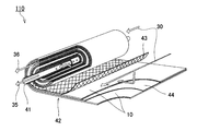
- the membrane separation device 110 of the present embodiment includes a central tube 41 and a laminate 42.
- the laminate 42 contains the separation membrane 10.
- the membrane separation device 110 is a spiral type membrane element.
- the central canal 41 has a cylindrical shape. On the surface of the central canal 41, a plurality of holes for allowing the permeated fluid 35 to flow into the central canal 41 are formed.
- the material of the central tube 41 include resins such as acrylonitrile / butadiene / styrene copolymer resin (ABS resin), polyphenylene ether resin (PPE resin), and polysulfon resin (PSF resin); metals such as stainless steel and titanium. Be done.
- the inner diameter of the central canal 41 is, for example, in the range of 20 to 100 mm.
- the laminated body 42 further includes a supply side flow path material 43 and a transmission side flow path material 44 in addition to the separation membrane 10.
- the laminate 42 is wound around the central canal 41.
- the membrane separation device 110 may further include an exterior material (not shown).
- a resin net made of polyphenylene sulfide (PPS) or ethylene-chlorotrifluoroethylene copolymer (ECTFE) can be used.
- Membrane separation using the membrane separation device 110 is performed by, for example, the following method.
- the space inside the central canal 41 is decompressed.
- the permeated fluid 35 that has passed through the separation membrane 10 of the laminated body 42 moves inside the central tube 41.
- the permeated fluid 35 is discharged to the outside through the central tube 41.
- the mixed liquid 30 (concentrated fluid 36) processed by the membrane separation device 110 is discharged to the outside from the other end of the wound laminate 42. As a result, water can be separated from the mixed liquid 30.
- Example 1 First, 1.54 g of zirconium chloride (ZrCl 4 : manufactured by Nacalai Tesque) and 1.21 g of 2-aminoterephthalic acid (manufactured by Tokyo Chemical Industry Co., Ltd.) were dissolved in 68.8 mL of DMF (manufactured by Nacalai Tesque). To the obtained solution, 0.66 mL of concentrated hydrochloric acid (manufactured by Nacalai Tesque, Inc.) was added, and the mixture was thoroughly stirred. Next, the solution was set in an autoclave (100 mL) and crystallized by a solvothermal method (100 ° C., 24 hours).
- ZrCl 4 manufactured by Nacalai Tesque
- 2-aminoterephthalic acid manufactured by Tokyo Chemical Industry Co., Ltd.
- the produced powder was allowed to cool to room temperature (25 ° C.) and then separated by a centrifuge (6000 rpm). The unreacted raw material was removed from the powder by washing the powder with methanol three times. The obtained yellow powder was added to 100 mL of methanol and stirred overnight. The powder was separated by a centrifuge (6000 rpm) and dried at 70 ° C. As a result, the metal-organic framework of Example 1 (UiO-66 (Zr) -NH 2 ) was obtained.
- Example 1 The structure of the metal-organic framework of Example 1 was analyzed by 1 H-NMR measurement and X-ray diffraction (XRD) measurement.
- XRD X-ray diffraction
- the zeta potential in DMF was measured by the following method. First, 5 mg of the metal-organic framework was added to 30 mL of DMF to prepare a suspension. The suspension was subjected to sonication (20 min) to uniformly disperse the metal-organic framework in DMF. For this suspension, the zeta potential was measured three times using a zeta potential / particle size measurement system (ELSZ-DN2 manufactured by Otsuka Electronics Co., Ltd.), and the average value was used as the zeta potential of the metal-organic framework in DMF. Identified.
- ELSZ-DN2 zeta potential / particle size measurement system
- the separation membrane was prepared by the following method.
- tetracarboxylic acid dianhydride bis (1,3-dioxo-1,3-dihydroisobenzofuran-5-carboxylic acid) ethylene (in the formula (4), A is the linking group 18 and R Compounds in which 1 to R 6 are hydrogen atoms) were prepared.
- diamine compounds 4,4'-diaminodiphenyl ether (in formula (5), B is a linking group 21 and Ar 1 and Ar 2 are p-phenylene groups) and 3,5-diaminobenzoic acid. Prepared.
- the diamine compound was dissolved in N-methyl-2-pyrrolidone to obtain a solution.
- Polyamic acid was obtained by adding tetracarboxylic dianhydride to the obtained solution under room temperature conditions.
- a polyimide was obtained by chemically imidizing the polyamic acid with triethylamine and acetic anhydride. Chemical imidization was performed in N-methyl-2-pyrrolidone under the condition of 60 ° C.
- the ratio of the structural unit derived from 3,5-diaminobenzoic acid to all the structural units derived from the diamine compound was 10 mol%.
- the polyimide was dissolved in 1,3-dioxolane to obtain a solution.
- a polyimide solution was added to the dispersion liquid containing the metal-organic framework of Example 1.
- a coating film was obtained by applying the obtained mixed solution onto a porous support.
- a UF membrane (ultrafiltration membrane) RS-50 (a laminate of a PVDF porous layer and a PET non-woven fabric) manufactured by Nitto Denko Corporation was used.
- the coating film was formed on the PVDF porous layer of RS-50.
- the separation functional layer was formed by drying the coating film.
- the content of the metal-organic framework in the separating functional layer was 5 wt%. As a result, a separation membrane for character evaluation was obtained.
- the separation coefficient ⁇ of the separation membrane and the flux of water that permeated the separation membrane were measured by the following method.
- the separation membrane was set in the metal cell and sealed with an O-ring to prevent leakage.
- 250 mL of the mixed liquid was injected into the metal cell so that the mixed liquid was in contact with the main surface of the separation membrane on the separation function layer side.
- the mixed liquid consisted substantially of ethanol and water.
- the concentration of ethanol in the mixed liquid was 50 vol% when the temperature of the mixed liquid was measured at 20 ° C.
- the metal cell was heated to 60 ° C. by a hot water bath.
- the space in the metal cell adjacent to the main surface of the separation membrane on the porous support side was depressurized. At this time, the pressure in this space was reduced so that the pressure in the space was 100 kPa smaller than the atmospheric pressure in the measurement environment. As a result, a gas permeation fluid was obtained.
- the permeated fluid was liquefied by cooling the permeated fluid of the gas with liquid nitrogen at -196 ° C.
- the composition of the liquid permeation fluid was analyzed using gas chromatography.
- the separation coefficient ⁇ of the separation membrane and the flux F of water permeating the separation membrane were calculated based on the composition of the permeated fluid, the weight of the permeated fluid, and the like.
- Example 2 0.5 g of the metal-organic framework (UiO-66 (Zr) -NH 2 ) of Example 1 and 0.5 g of 2-hydroxyterephthalic acid (manufactured by Tokyo Chemical Industry Co., Ltd.) were added to 33 mL of DMF, and the mixture was added to 33 mL of DMF for 10 minutes at room temperature. Stirred. The obtained suspension was heated to 120 ° C. and stirred for 5 minutes (0.08 hours). After allowing the suspension to cool to room temperature, the powder in the suspension was recovered by a centrifuge (6000 rpm). The obtained yellow powder was added to 100 mL of methanol and stirred overnight.
- the metal-organic framework (UiO-66 (Zr) -NH 2 ) of Example 1 0.5 g of the metal-organic framework (UiO-66 (Zr) -NH 2 ) of Example 1 and 0.5 g of 2-hydroxyterephthalic acid (manufactured by Tokyo Chemical Industry Co., Ltd.) were
- the powder was recovered by a centrifuge (6000 rpm) and dried at 70 ° C.
- the metal-organic framework of Example 2 (UiO-66 (Zr) -NH 2 , OH) was obtained.
- structural analysis, zeta potential measurement in DMF, and characteristic evaluation of the separation membrane were performed by the same method as in Example 1. Further, based on the result of 1 H-NMR measurement of the metal organic structure, the total value of the number of moles of the first functional group (amino group) and the number of moles of the second functional group (hydroxy group) in the metal organic structure. The ratio P1 of the number of moles of the second functional group to 2 was calculated.
- Example 3 The characteristics of the separation membrane were evaluated by the same method as in Example 2 except that the content of the metal-organic framework in the separation functional layer was changed to 10 wt%.
- Example 4 0.5 g of the metal-organic framework of Example 1 (UiO-66 (Zr) -NH 2 ) and 1.68 g of 2-nitroterephthalic acid (manufactured by Tokyo Chemical Industry Co., Ltd.) were added to 33 mL of DMF, and the mixture was added to 33 mL of DMF for 10 minutes at room temperature. Stirred. The obtained suspension was heated to 120 ° C. and stirred for 5 minutes (0.08 hours). After allowing the suspension to cool to room temperature, the powder in the suspension was recovered by a centrifuge (6000 rpm). The obtained yellow powder was added to 100 mL of methanol and stirred overnight.
- the powder was recovered by a centrifuge (6000 rpm) and dried at 70 ° C.
- the metal-organic framework of Example 4 (UiO-66 (Zr) -NH 2 , NO 2 ) was obtained.
- structural analysis, zeta potential measurement in DMF, and characteristic evaluation of the separation membrane were performed by the same method as in Example 1. Further, based on the result of 1 H-NMR measurement of the metal organic structure, the total value of the number of moles of the first functional group (amino group) and the number of moles of the second functional group (nitro group) in the metal organic structure. The ratio P1 of the number of moles of the second functional group to 2 was calculated.
- Example 5 0.5 g of the metal-organic framework of Example 1 (UiO-66 (Zr) -NH 2 ) and 0.58 g of trimellitic acid (manufactured by Nacalai Tesque) were added to 33 mL of DMF, and the mixture was stirred at room temperature for 10 minutes. The obtained suspension was heated to 120 ° C. and stirred for 5 minutes (0.08 hours). After allowing the suspension to cool to room temperature, the powder in the suspension was recovered by a centrifuge (6000 rpm). The obtained yellow powder was added to 100 mL of methanol and stirred overnight. The powder was recovered by a centrifuge (6000 rpm) and dried at 70 ° C.
- the metal-organic framework of Example 5 (UiO-66 (Zr) -NH 2 , COOH) was obtained.
- structural analysis, zeta potential measurement in DMF, and characteristic evaluation of the separation membrane were performed by the same method as in Example 1. Further, based on the result of 1 H-NMR measurement of the metal organic structure, the total value of the number of moles of the first functional group (amino group) and the number of moles of the second functional group (carboxyl group) in the metal organic structure. The ratio P1 of the number of moles of the second functional group to 2 was calculated.
- Example 6 The metal-organic framework of Example 6 (UiO-66 (Zr) -NH 2 , COOH) was obtained by the same method as in Example 5, except that the suspension heated to 120 ° C. was stirred for 24 hours.
- the metal-organic framework of Example 6 was structurally analyzed and the characteristics of the separation membrane were evaluated by the same method as in Example 1. Further, based on the result of 1 H-NMR measurement of the metal organic structure, the total value of the number of moles of the first functional group (amino group) and the number of moles of the second functional group (carboxyl group) in the metal organic structure. The ratio P1 of the number of moles of the second functional group to 2 was calculated.
- Example 7 zirconium oxynitrate (ZrO (NO 3) 2 ⁇ 2H 2 O: manufactured by Nacalai Tesque) was 1.80g and trimellitic acid 3.27g was added to a mixture of DMF54mL and 36.4g benzoic acid, by stirring These were dissolved. Next, the solution was set in an autoclave (100 mL) and crystallized by a solvothermal method (150 ° C., 24 hours). The produced powder was allowed to cool to room temperature and then separated by a centrifuge (6000 rpm). The unreacted raw material was removed from the powder by washing the powder with methanol three times.
- ZrO (NO 3) 2 ⁇ 2H 2 O: manufactured by Nacalai Tesque zirconium oxynitrate
- Example 7 the metal-organic framework of Example 7 (UiO-66 (Zr) -COOH) was obtained.
- structural analysis, zeta potential measurement in DMF, and characteristic evaluation of the separation membrane were performed by the same method as in Example 1.
- Example 8 0.5 g of the metal-organic framework of Example 1 (UiO-66 (Zr) -NH 2 ) and 1.25 g of terephthalic acid (manufactured by Nacalai Tesque) were added to 33 mL of DMF, and the mixture was stirred at room temperature for 10 minutes. The obtained suspension was heated to 120 ° C. and stirred for 5 minutes (0.08 hours). After allowing the suspension to cool to room temperature, the powder in the suspension was recovered by a centrifuge (6000 rpm). The obtained yellow powder was added to 100 mL of methanol and stirred overnight. The powder was recovered by a centrifuge (6000 rpm) and dried at 70 ° C.
- the metal-organic framework of Example 8 (UiO-66 (Zr) -NH 2 , H) was obtained.
- structural analysis, zeta potential measurement in DMF, and characteristic evaluation of the separation membrane were performed by the same method as in Example 1.
- the ratio of the number of moles of terephthalic acid to the total value of the number of moles of 2-aminoterephthalic acid and the number of moles of terephthalic acid in the metal-organic framework is calculated. Calculated.
- the metal-organic frameworks of Examples 2 to 5 containing a second functional group (hydroxy group, nitro group or carboxyl group) and having a ratio P1 adjusted to 30 mol% or less are other metal-organic frameworks. Compared with the structure, it was suitable for improving the flow flux F of the permeated fluid (water) permeating the separation membrane.
- the separation coefficient ⁇ of the separation membrane was 20 or more, which was a practically sufficient value.
- the thickness of the separation functional layer in the separation membrane for character evaluation was unified to 1 to 1.5 ⁇ m.
- the separation coefficient ⁇ of the separation membrane was 66.6, and the water flux F was 0.21 kg / m 2 / hr. ..
- the metal-organic framework of this embodiment is suitable as a filler for a separation membrane.
- This separation membrane is useful for separating water from a mixed liquid containing alcohol and water, especially for purification of bioethanol.
Landscapes
- Chemical & Material Sciences (AREA)
- Chemical Kinetics & Catalysis (AREA)
- Engineering & Computer Science (AREA)
- Water Supply & Treatment (AREA)
- Organic Chemistry (AREA)
- Dispersion Chemistry (AREA)
- Inorganic Chemistry (AREA)
- Manufacturing & Machinery (AREA)
- Separation Using Semi-Permeable Membranes (AREA)
- Organic Low-Molecular-Weight Compounds And Preparation Thereof (AREA)
Priority Applications (4)
| Application Number | Priority Date | Filing Date | Title |
|---|---|---|---|
| EP21774502.5A EP4130012A1 (en) | 2020-03-25 | 2021-02-24 | Metal-organic framework, separation film, and method for producing metal-organic framework |
| JP2022509434A JPWO2021192791A1 (https=) | 2020-03-25 | 2021-02-24 | |
| CN202180019139.9A CN115279775A (zh) | 2020-03-25 | 2021-02-24 | 金属有机结构体、分离膜及金属有机结构体的制造方法 |
| US17/912,840 US20230146282A1 (en) | 2020-03-25 | 2021-02-24 | Metal organic framework, separation membrane, and method for producing metal organic framework |
Applications Claiming Priority (2)
| Application Number | Priority Date | Filing Date | Title |
|---|---|---|---|
| JP2020054139 | 2020-03-25 | ||
| JP2020-054139 | 2020-03-25 |
Publications (1)
| Publication Number | Publication Date |
|---|---|
| WO2021192791A1 true WO2021192791A1 (ja) | 2021-09-30 |
Family
ID=77891675
Family Applications (1)
| Application Number | Title | Priority Date | Filing Date |
|---|---|---|---|
| PCT/JP2021/006895 Ceased WO2021192791A1 (ja) | 2020-03-25 | 2021-02-24 | 金属有機構造体、分離膜及び金属有機構造体の製造方法 |
Country Status (5)
| Country | Link |
|---|---|
| US (1) | US20230146282A1 (https=) |
| EP (1) | EP4130012A1 (https=) |
| JP (1) | JPWO2021192791A1 (https=) |
| CN (1) | CN115279775A (https=) |
| WO (1) | WO2021192791A1 (https=) |
Cited By (1)
| Publication number | Priority date | Publication date | Assignee | Title |
|---|---|---|---|---|
| WO2023238467A1 (ja) * | 2022-06-08 | 2023-12-14 | 愛三工業株式会社 | 吸着材料および吸着装置 |
Citations (1)
| Publication number | Priority date | Publication date | Assignee | Title |
|---|---|---|---|---|
| JP2011501739A (ja) | 2007-10-01 | 2011-01-13 | サントル ナショナル ドゥ ラ ルシェルシュ スィヤンティフィック(セーエヌエルエス) | 表面修飾した固体無機/有機ハイブリッド |
-
2021
- 2021-02-24 EP EP21774502.5A patent/EP4130012A1/en not_active Withdrawn
- 2021-02-24 JP JP2022509434A patent/JPWO2021192791A1/ja active Pending
- 2021-02-24 WO PCT/JP2021/006895 patent/WO2021192791A1/ja not_active Ceased
- 2021-02-24 CN CN202180019139.9A patent/CN115279775A/zh active Pending
- 2021-02-24 US US17/912,840 patent/US20230146282A1/en not_active Abandoned
Patent Citations (1)
| Publication number | Priority date | Publication date | Assignee | Title |
|---|---|---|---|---|
| JP2011501739A (ja) | 2007-10-01 | 2011-01-13 | サントル ナショナル ドゥ ラ ルシェルシュ スィヤンティフィック(セーエヌエルエス) | 表面修飾した固体無機/有機ハイブリッド |
Non-Patent Citations (5)
| Title |
|---|
| RADA ZANA HASSAN, ABID HUSSEIN RASOOL, SUN HONGQI, WANG SHAOBIN: "Bifunctionalized Metal Organic Frameworks, UiO-66-NO2-N (N = -NH 2, -(OH)2, -(COOH)2), for Enhanced Adsorption and Selectivity of CO 2 and N 2", JOURNAL OF CHEMICAL AND ENGINEERING DATA., AMERICAN CHEMICAL SOCIETY., US, vol. 60, no. 7, 9 July 2015 (2015-07-09), US , pages 2152 - 2161, XP055861678, ISSN: 0021-9568, DOI: 10.1021/acs.jced.5b00229 * |
| RADA, Z. H ET AL.: "Effects of -N02 and-NH2 functional groups in mixed-linker Zr-based MOFs on gas adsorption of C02 and CH 4", PROGRESS IN NATURAL SCIENCE : MATERIALS INTERNATIONAL, vol. 28, no. 2, 2018, pages 160 - 167, XP085397203, DOI: 10.1016/j.pnsc.2018.01.016 * |
| ROBERT F. FEDORS, POLYMER ENGINEERING AND SCIENCE, 1974, pages 147 - 154 |
| TADDEI, M ET AL.: "Post-Synthetic Ligand Exchange in Zirconium-Based Metal-Organic Frameworks: Beware of The Defects!", ANGEW CHEM. INT. ED. ENGL., vol. 57, no. 36, 2018, pages 11706 - 11710, XP055861675 * |
| TANH JEAZET, H. B ET AL.: "Metal-organic frameworks in mixed-matrix membranes for gas separation", DALTON TRANS, vol. 41, no. 46, 2012, pages 14003 - 14027, XP055861673 * |
Cited By (3)
| Publication number | Priority date | Publication date | Assignee | Title |
|---|---|---|---|---|
| WO2023238467A1 (ja) * | 2022-06-08 | 2023-12-14 | 愛三工業株式会社 | 吸着材料および吸着装置 |
| JP2023179891A (ja) * | 2022-06-08 | 2023-12-20 | 愛三工業株式会社 | 吸着材料および吸着装置 |
| JP7840789B2 (ja) | 2022-06-08 | 2026-04-06 | 愛三工業株式会社 | 吸着装置 |
Also Published As
| Publication number | Publication date |
|---|---|
| US20230146282A1 (en) | 2023-05-11 |
| EP4130012A1 (en) | 2023-02-08 |
| CN115279775A (zh) | 2022-11-01 |
| JPWO2021192791A1 (https=) | 2021-09-30 |
Similar Documents
| Publication | Publication Date | Title |
|---|---|---|
| Zhang et al. | Challenges and recent advances in MOF–polymer composite membranes for gas separation | |
| Liang et al. | Water permeance, permeability and desalination properties of the sulfonic acid functionalized composite pervaporation membranes | |
| Shamsaei et al. | Aqueous phase synthesis of ZIF-8 membrane with controllable location on an asymmetrically porous polymer substrate | |
| Sabetghadam et al. | Metal organic framework crystals in mixed‐matrix membranes: impact of the filler morphology on the gas separation performance | |
| Lin et al. | Mixed matrix membranes with strengthened MOFs/polymer interfacial interaction and improved membrane performance | |
| Yao et al. | Zeolitic imidazolate framework composite membranes and thin films: synthesis and applications | |
| Fan et al. | Nanodisperse ZIF-8/PDMS hybrid membranes for biobutanol permselective pervaporation | |
| Yuan et al. | Nanosized core–shell zeolitic imidazolate frameworks‐based membranes for gas separation | |
| CN111282405A (zh) | 一种改性金属有机骨架纳米片及其制备方法 | |
| CN112934007B (zh) | 一种zif-8前驱体转化制备zif-8/go复合气体分离膜的方法 | |
| KR20140073300A (ko) | 분리막, 및 상기 분리막을 포함하는 수처리 장치 | |
| Yan et al. | Enhanced CO2/N2 separation in hybrid composite membrane via dispersion of hollow defect‐engineered Zr‐MOF nanoparticles | |
| US11786870B2 (en) | CMS membrane, method for the production thereof and use thereof | |
| JP7337629B2 (ja) | 分離膜及び膜分離方法 | |
| WO2022059369A1 (ja) | 分離膜 | |
| WO2021192791A1 (ja) | 金属有機構造体、分離膜及び金属有機構造体の製造方法 | |
| WO2021192745A1 (ja) | 分離膜 | |
| WO2021157433A1 (ja) | 分離膜及び金属有機構造体 | |
| JP2025152873A (ja) | 分離機能層、及び分離膜 | |
| EP4450150A1 (en) | Separation functional layer, separation membrane, and method for producing separation functional layer | |
| Momeni et al. | Hybrid membranes for carbon capture | |
| CN118369151A (zh) | 分离功能层、分离膜及分离功能层的制造方法 | |
| JP2025137156A (ja) | 分離機能層、分離膜、及び分離機能層の製造方法 | |
| JP2025156069A (ja) | 分離機能層、及び分離膜 | |
| WO2024014285A1 (ja) | 分離膜、及びその製造方法 |
Legal Events
| Date | Code | Title | Description |
|---|---|---|---|
| 121 | Ep: the epo has been informed by wipo that ep was designated in this application |
Ref document number: 21774502 Country of ref document: EP Kind code of ref document: A1 |
|
| ENP | Entry into the national phase |
Ref document number: 2022509434 Country of ref document: JP Kind code of ref document: A |
|
| NENP | Non-entry into the national phase |
Ref country code: DE |
|
| ENP | Entry into the national phase |
Ref document number: 2021774502 Country of ref document: EP Effective date: 20221025 |