WO2021192791A1 - 金属有機構造体、分離膜及び金属有機構造体の製造方法 - Google Patents
金属有機構造体、分離膜及び金属有機構造体の製造方法 Download PDFInfo
- Publication number
- WO2021192791A1 WO2021192791A1 PCT/JP2021/006895 JP2021006895W WO2021192791A1 WO 2021192791 A1 WO2021192791 A1 WO 2021192791A1 JP 2021006895 W JP2021006895 W JP 2021006895W WO 2021192791 A1 WO2021192791 A1 WO 2021192791A1
- Authority
- WO
- WIPO (PCT)
- Prior art keywords
- metal
- group
- functional group
- organic
- organic framework
- Prior art date
Links
- 238000000926 separation method Methods 0.000 title claims abstract description 152
- 239000012621 metal-organic framework Substances 0.000 title claims abstract description 137
- 238000004519 manufacturing process Methods 0.000 title claims description 18
- 125000000524 functional group Chemical group 0.000 claims abstract description 110
- 239000013110 organic ligand Substances 0.000 claims abstract description 85
- 229910021645 metal ion Inorganic materials 0.000 claims abstract description 30
- 125000002887 hydroxy group Chemical group [H]O* 0.000 claims abstract description 19
- 125000003178 carboxy group Chemical group [H]OC(*)=O 0.000 claims abstract description 16
- 125000000449 nitro group Chemical group [O-][N+](*)=O 0.000 claims abstract description 9
- 239000012528 membrane Substances 0.000 claims description 118
- XLYOFNOQVPJJNP-UHFFFAOYSA-N water Substances O XLYOFNOQVPJJNP-UHFFFAOYSA-N 0.000 claims description 71
- LFQSCWFLJHTTHZ-UHFFFAOYSA-N Ethanol Chemical compound CCO LFQSCWFLJHTTHZ-UHFFFAOYSA-N 0.000 claims description 70
- 239000007788 liquid Substances 0.000 claims description 54
- 238000000034 method Methods 0.000 claims description 44
- ZMXDDKWLCZADIW-UHFFFAOYSA-N N,N-Dimethylformamide Chemical compound CN(C)C=O ZMXDDKWLCZADIW-UHFFFAOYSA-N 0.000 claims description 35
- 239000004642 Polyimide Substances 0.000 claims description 34
- 229920001721 polyimide Polymers 0.000 claims description 34
- 125000003118 aryl group Chemical group 0.000 claims description 27
- 125000004432 carbon atom Chemical group C* 0.000 claims description 23
- 125000005647 linker group Chemical group 0.000 claims description 21
- 239000002243 precursor Substances 0.000 claims description 20
- 239000011159 matrix material Substances 0.000 claims description 18
- 125000003545 alkoxy group Chemical group 0.000 claims description 15
- 125000004435 hydrogen atom Chemical group [H]* 0.000 claims description 14
- 239000002346 layers by function Substances 0.000 claims description 14
- 125000001424 substituent group Chemical group 0.000 claims description 12
- 125000005843 halogen group Chemical group 0.000 claims description 11
- 125000003277 amino group Chemical group 0.000 claims description 8
- 125000000542 sulfonic acid group Chemical group 0.000 claims description 8
- OKTJSMMVPCPJKN-UHFFFAOYSA-N Carbon Chemical compound [C] OKTJSMMVPCPJKN-UHFFFAOYSA-N 0.000 claims description 6
- 150000001990 dicarboxylic acid derivatives Chemical class 0.000 claims description 5
- 150000003503 terephthalic acid derivatives Chemical class 0.000 claims description 5
- 229910052799 carbon Inorganic materials 0.000 claims description 4
- 125000000843 phenylene group Chemical group C1(=C(C=CC=C1)*)* 0.000 claims description 4
- QCWXUUIWCKQGHC-UHFFFAOYSA-N Zirconium Chemical compound [Zr] QCWXUUIWCKQGHC-UHFFFAOYSA-N 0.000 claims description 3
- 229910052726 zirconium Inorganic materials 0.000 claims description 3
- 238000003763 carbonization Methods 0.000 claims 1
- 125000001183 hydrocarbyl group Chemical group 0.000 claims 1
- 239000012530 fluid Substances 0.000 abstract description 29
- 230000004907 flux Effects 0.000 abstract description 19
- 239000012466 permeate Substances 0.000 abstract description 12
- -1 small molecule compounds Chemical class 0.000 description 32
- 150000002430 hydrocarbons Chemical group 0.000 description 25
- OKKJLVBELUTLKV-UHFFFAOYSA-N Methanol Chemical compound OC OKKJLVBELUTLKV-UHFFFAOYSA-N 0.000 description 24
- 239000000945 filler Substances 0.000 description 24
- 239000000843 powder Substances 0.000 description 22
- 229910052751 metal Inorganic materials 0.000 description 18
- 239000002184 metal Substances 0.000 description 18
- 238000001179 sorption measurement Methods 0.000 description 17
- SECXISVLQFMRJM-UHFFFAOYSA-N N-Methylpyrrolidone Chemical compound CN1CCCC1=O SECXISVLQFMRJM-UHFFFAOYSA-N 0.000 description 16
- 239000000725 suspension Substances 0.000 description 16
- 239000010410 layer Substances 0.000 description 15
- 238000005259 measurement Methods 0.000 description 15
- 239000013207 UiO-66 Substances 0.000 description 13
- 125000004429 atom Chemical group 0.000 description 13
- 239000011248 coating agent Substances 0.000 description 12
- 238000000576 coating method Methods 0.000 description 12
- 239000000243 solution Substances 0.000 description 11
- GTDPSWPPOUPBNX-UHFFFAOYSA-N ac1mqpva Chemical compound CC12C(=O)OC(=O)C1(C)C1(C)C2(C)C(=O)OC1=O GTDPSWPPOUPBNX-UHFFFAOYSA-N 0.000 description 10
- 125000006158 tetracarboxylic acid group Chemical group 0.000 description 10
- 239000000203 mixture Substances 0.000 description 9
- 125000004430 oxygen atom Chemical group O* 0.000 description 9
- 238000011156 evaluation Methods 0.000 description 8
- 239000000463 material Substances 0.000 description 8
- 125000004433 nitrogen atom Chemical group N* 0.000 description 8
- 239000002245 particle Substances 0.000 description 8
- 229920005575 poly(amic acid) Polymers 0.000 description 8
- 239000000126 substance Substances 0.000 description 8
- 125000001140 1,4-phenylene group Chemical group [H]C1=C([H])C([*:2])=C([H])C([H])=C1[*:1] 0.000 description 7
- 238000005160 1H NMR spectroscopy Methods 0.000 description 7
- WFDIJRYMOXRFFG-UHFFFAOYSA-N Acetic anhydride Chemical compound CC(=O)OC(C)=O WFDIJRYMOXRFFG-UHFFFAOYSA-N 0.000 description 6
- KFZMGEQAYNKOFK-UHFFFAOYSA-N Isopropanol Chemical compound CC(C)O KFZMGEQAYNKOFK-UHFFFAOYSA-N 0.000 description 6
- KKEYFWRCBNTPAC-UHFFFAOYSA-N Terephthalic acid Chemical compound OC(=O)C1=CC=C(C(O)=O)C=C1 KKEYFWRCBNTPAC-UHFFFAOYSA-N 0.000 description 6
- ZMANZCXQSJIPKH-UHFFFAOYSA-N Triethylamine Chemical compound CCN(CC)CC ZMANZCXQSJIPKH-UHFFFAOYSA-N 0.000 description 6
- 238000010438 heat treatment Methods 0.000 description 6
- 229920005989 resin Polymers 0.000 description 6
- 239000011347 resin Substances 0.000 description 6
- ARCGXLSVLAOJQL-UHFFFAOYSA-N trimellitic acid Chemical compound OC(=O)C1=CC=C(C(O)=O)C(C(O)=O)=C1 ARCGXLSVLAOJQL-UHFFFAOYSA-N 0.000 description 6
- 125000002947 alkylene group Chemical group 0.000 description 5
- 239000007789 gas Substances 0.000 description 5
- 229910052757 nitrogen Inorganic materials 0.000 description 5
- 238000012916 structural analysis Methods 0.000 description 5
- 125000004434 sulfur atom Chemical group 0.000 description 5
- 238000000733 zeta-potential measurement Methods 0.000 description 5
- WNXJIVFYUVYPPR-UHFFFAOYSA-N 1,3-dioxolane Chemical compound C1COCO1 WNXJIVFYUVYPPR-UHFFFAOYSA-N 0.000 description 4
- CDOWNLMZVKJRSC-UHFFFAOYSA-N 2-hydroxyterephthalic acid Chemical compound OC(=O)C1=CC=C(C(O)=O)C(O)=C1 CDOWNLMZVKJRSC-UHFFFAOYSA-N 0.000 description 4
- IJGRMHOSHXDMSA-UHFFFAOYSA-N Atomic nitrogen Chemical compound N#N IJGRMHOSHXDMSA-UHFFFAOYSA-N 0.000 description 4
- VEXZGXHMUGYJMC-UHFFFAOYSA-N Hydrochloric acid Chemical compound Cl VEXZGXHMUGYJMC-UHFFFAOYSA-N 0.000 description 4
- WPYMKLBDIGXBTP-UHFFFAOYSA-N benzoic acid Chemical compound OC(=O)C1=CC=CC=C1 WPYMKLBDIGXBTP-UHFFFAOYSA-N 0.000 description 4
- 125000001033 ether group Chemical group 0.000 description 4
- 125000001997 phenyl group Chemical group [H]C1=C([H])C([H])=C(*)C([H])=C1[H] 0.000 description 4
- 125000005543 phthalimide group Chemical group 0.000 description 4
- KKTUQAYCCLMNOA-UHFFFAOYSA-N 2,3-diaminobenzoic acid Chemical compound NC1=CC=CC(C(O)=O)=C1N KKTUQAYCCLMNOA-UHFFFAOYSA-N 0.000 description 3
- GPNNOCMCNFXRAO-UHFFFAOYSA-N 2-aminoterephthalic acid Chemical compound NC1=CC(C(O)=O)=CC=C1C(O)=O GPNNOCMCNFXRAO-UHFFFAOYSA-N 0.000 description 3
- UENRXLSRMCSUSN-UHFFFAOYSA-N 3,5-diaminobenzoic acid Chemical compound NC1=CC(N)=CC(C(O)=O)=C1 UENRXLSRMCSUSN-UHFFFAOYSA-N 0.000 description 3
- 239000004215 Carbon black (E152) Substances 0.000 description 3
- JUJWROOIHBZHMG-UHFFFAOYSA-N Pyridine Chemical group C1=CC=NC=C1 JUJWROOIHBZHMG-UHFFFAOYSA-N 0.000 description 3
- 238000001035 drying Methods 0.000 description 3
- 125000004185 ester group Chemical group 0.000 description 3
- 125000001072 heteroaryl group Chemical group 0.000 description 3
- 125000005842 heteroatom Chemical group 0.000 description 3
- 229930195733 hydrocarbon Natural products 0.000 description 3
- 150000002739 metals Chemical class 0.000 description 3
- 125000002950 monocyclic group Chemical group 0.000 description 3
- 239000003960 organic solvent Substances 0.000 description 3
- 239000003495 polar organic solvent Substances 0.000 description 3
- 125000003367 polycyclic group Chemical group 0.000 description 3
- 229920000642 polymer Polymers 0.000 description 3
- 239000002904 solvent Substances 0.000 description 3
- 238000004729 solvothermal method Methods 0.000 description 3
- 229910052717 sulfur Inorganic materials 0.000 description 3
- 125000002030 1,2-phenylene group Chemical group [H]C1=C([H])C([*:1])=C([*:2])C([H])=C1[H] 0.000 description 2
- 239000005711 Benzoic acid Substances 0.000 description 2
- KAKZBPTYRLMSJV-UHFFFAOYSA-N Butadiene Chemical compound C=CC=C KAKZBPTYRLMSJV-UHFFFAOYSA-N 0.000 description 2
- 229920001780 ECTFE Polymers 0.000 description 2
- FXHOOIRPVKKKFG-UHFFFAOYSA-N N,N-Dimethylacetamide Chemical compound CN(C)C(C)=O FXHOOIRPVKKKFG-UHFFFAOYSA-N 0.000 description 2
- 239000002033 PVDF binder Substances 0.000 description 2
- 239000004721 Polyphenylene oxide Substances 0.000 description 2
- 239000004734 Polyphenylene sulfide Substances 0.000 description 2
- VYPSYNLAJGMNEJ-UHFFFAOYSA-N Silicium dioxide Chemical compound O=[Si]=O VYPSYNLAJGMNEJ-UHFFFAOYSA-N 0.000 description 2
- XUIMIQQOPSSXEZ-UHFFFAOYSA-N Silicon Chemical group [Si] XUIMIQQOPSSXEZ-UHFFFAOYSA-N 0.000 description 2
- PPBRXRYQALVLMV-UHFFFAOYSA-N Styrene Chemical compound C=CC1=CC=CC=C1 PPBRXRYQALVLMV-UHFFFAOYSA-N 0.000 description 2
- 238000002441 X-ray diffraction Methods 0.000 description 2
- 239000002253 acid Substances 0.000 description 2
- 125000003368 amide group Chemical group 0.000 description 2
- 235000010233 benzoic acid Nutrition 0.000 description 2
- 230000005540 biological transmission Effects 0.000 description 2
- 238000009835 boiling Methods 0.000 description 2
- 230000008859 change Effects 0.000 description 2
- 239000003795 chemical substances by application Substances 0.000 description 2
- 150000001875 compounds Chemical class 0.000 description 2
- 230000018044 dehydration Effects 0.000 description 2
- 238000006297 dehydration reaction Methods 0.000 description 2
- 229910001873 dinitrogen Inorganic materials 0.000 description 2
- 125000000468 ketone group Chemical group 0.000 description 2
- BDAGIHXWWSANSR-UHFFFAOYSA-N methanoic acid Natural products OC=O BDAGIHXWWSANSR-UHFFFAOYSA-N 0.000 description 2
- 239000011259 mixed solution Substances 0.000 description 2
- 230000004048 modification Effects 0.000 description 2
- 238000012986 modification Methods 0.000 description 2
- UJVRJBAUJYZFIX-UHFFFAOYSA-N nitric acid;oxozirconium Chemical compound [Zr]=O.O[N+]([O-])=O.O[N+]([O-])=O UJVRJBAUJYZFIX-UHFFFAOYSA-N 0.000 description 2
- QUMITRDILMWWBC-UHFFFAOYSA-N nitroterephthalic acid Chemical compound OC(=O)C1=CC=C(C(O)=O)C([N+]([O-])=O)=C1 QUMITRDILMWWBC-UHFFFAOYSA-N 0.000 description 2
- 239000004745 nonwoven fabric Substances 0.000 description 2
- 229920002492 poly(sulfone) Polymers 0.000 description 2
- 229920001955 polyphenylene ether Polymers 0.000 description 2
- 229920000069 polyphenylene sulfide Polymers 0.000 description 2
- 229920002620 polyvinyl fluoride Polymers 0.000 description 2
- 229920002981 polyvinylidene fluoride Polymers 0.000 description 2
- 239000013259 porous coordination polymer Substances 0.000 description 2
- 239000002994 raw material Substances 0.000 description 2
- 150000003839 salts Chemical class 0.000 description 2
- 238000003756 stirring Methods 0.000 description 2
- 125000000472 sulfonyl group Chemical group *S(*)(=O)=O 0.000 description 2
- 125000000101 thioether group Chemical group 0.000 description 2
- 238000005406 washing Methods 0.000 description 2
- DUNKXUFBGCUVQW-UHFFFAOYSA-J zirconium tetrachloride Chemical compound Cl[Zr](Cl)(Cl)Cl DUNKXUFBGCUVQW-UHFFFAOYSA-J 0.000 description 2
- GBNDTYKAOXLLID-UHFFFAOYSA-N zirconium(4+) ion Chemical compound [Zr+4] GBNDTYKAOXLLID-UHFFFAOYSA-N 0.000 description 2
- GEYOCULIXLDCMW-UHFFFAOYSA-N 1,2-phenylenediamine Chemical compound NC1=CC=CC=C1N GEYOCULIXLDCMW-UHFFFAOYSA-N 0.000 description 1
- CNCGBKWWMNGKIG-UHFFFAOYSA-N 1,3-dioxo-2-benzofuran-5-carboxylic acid ethene Chemical group C=C.O=C1OC(C2=CC(=CC=C12)C(=O)O)=O.O=C1OC(C2=CC(=CC=C12)C(=O)O)=O CNCGBKWWMNGKIG-UHFFFAOYSA-N 0.000 description 1
- 125000001989 1,3-phenylene group Chemical group [H]C1=C([H])C([*:1])=C([H])C([*:2])=C1[H] 0.000 description 1
- OSWFIVFLDKOXQC-UHFFFAOYSA-N 4-(3-methoxyphenyl)aniline Chemical compound COC1=CC=CC(C=2C=CC(N)=CC=2)=C1 OSWFIVFLDKOXQC-UHFFFAOYSA-N 0.000 description 1
- HLBLWEWZXPIGSM-UHFFFAOYSA-N 4-Aminophenyl ether Chemical compound C1=CC(N)=CC=C1OC1=CC=C(N)C=C1 HLBLWEWZXPIGSM-UHFFFAOYSA-N 0.000 description 1
- NLHHRLWOUZZQLW-UHFFFAOYSA-N Acrylonitrile Chemical compound C=CC#N NLHHRLWOUZZQLW-UHFFFAOYSA-N 0.000 description 1
- 229920000049 Carbon (fiber) Polymers 0.000 description 1
- YLQBMQCUIZJEEH-UHFFFAOYSA-N Furan Chemical group C=1C=COC=1 YLQBMQCUIZJEEH-UHFFFAOYSA-N 0.000 description 1
- 239000004696 Poly ether ether ketone Substances 0.000 description 1
- 239000004698 Polyethylene Substances 0.000 description 1
- 239000004743 Polypropylene Substances 0.000 description 1
- YTPLMLYBLZKORZ-UHFFFAOYSA-N Thiophene Chemical group C=1C=CSC=1 YTPLMLYBLZKORZ-UHFFFAOYSA-N 0.000 description 1
- RTAQQCXQSZGOHL-UHFFFAOYSA-N Titanium Chemical compound [Ti] RTAQQCXQSZGOHL-UHFFFAOYSA-N 0.000 description 1
- 229910007926 ZrCl Inorganic materials 0.000 description 1
- 229910006219 ZrO(NO3)2·2H2O Inorganic materials 0.000 description 1
- 229920000122 acrylonitrile butadiene styrene Polymers 0.000 description 1
- 239000003463 adsorbent Substances 0.000 description 1
- 230000002776 aggregation Effects 0.000 description 1
- 238000004220 aggregation Methods 0.000 description 1
- 150000008064 anhydrides Chemical class 0.000 description 1
- 125000005577 anthracene group Chemical group 0.000 description 1
- 239000004760 aramid Substances 0.000 description 1
- 229920003235 aromatic polyamide Polymers 0.000 description 1
- HFACYLZERDEVSX-UHFFFAOYSA-N benzidine Chemical group C1=CC(N)=CC=C1C1=CC=C(N)C=C1 HFACYLZERDEVSX-UHFFFAOYSA-N 0.000 description 1
- 239000003054 catalyst Substances 0.000 description 1
- 239000000919 ceramic Substances 0.000 description 1
- 238000006243 chemical reaction Methods 0.000 description 1
- 229920006026 co-polymeric resin Polymers 0.000 description 1
- 230000000052 comparative effect Effects 0.000 description 1
- 238000001816 cooling Methods 0.000 description 1
- 239000002537 cosmetic Substances 0.000 description 1
- ZZTCPWRAHWXWCH-UHFFFAOYSA-N diphenylmethanediamine Chemical compound C=1C=CC=CC=1C(N)(N)C1=CC=CC=C1 ZZTCPWRAHWXWCH-UHFFFAOYSA-N 0.000 description 1
- 239000006185 dispersion Substances 0.000 description 1
- 238000009826 distribution Methods 0.000 description 1
- 239000003814 drug Substances 0.000 description 1
- 125000002573 ethenylidene group Chemical group [*]=C=C([H])[H] 0.000 description 1
- 125000001301 ethoxy group Chemical group [H]C([H])([H])C([H])([H])O* 0.000 description 1
- 125000001495 ethyl group Chemical group [H]C([H])([H])C([H])([H])* 0.000 description 1
- 125000000816 ethylene group Chemical group [H]C([H])([*:1])C([H])([H])[*:2] 0.000 description 1
- 238000001704 evaporation Methods 0.000 description 1
- 230000008020 evaporation Effects 0.000 description 1
- 239000000835 fiber Substances 0.000 description 1
- 239000006260 foam Substances 0.000 description 1
- 235000019253 formic acid Nutrition 0.000 description 1
- 238000004817 gas chromatography Methods 0.000 description 1
- 229920000126 latex Polymers 0.000 description 1
- 239000006262 metallic foam Substances 0.000 description 1
- 125000000956 methoxy group Chemical group [H]C([H])([H])O* 0.000 description 1
- 125000002496 methyl group Chemical group [H]C([H])([H])* 0.000 description 1
- 125000001570 methylene group Chemical group [H]C([H])([*:1])[*:2] 0.000 description 1
- 238000001000 micrograph Methods 0.000 description 1
- 150000007522 mineralic acids Chemical class 0.000 description 1
- 125000001624 naphthyl group Chemical group 0.000 description 1
- 229920001778 nylon Polymers 0.000 description 1
- 150000007524 organic acids Chemical class 0.000 description 1
- 235000005985 organic acids Nutrition 0.000 description 1
- 230000003204 osmotic effect Effects 0.000 description 1
- CMOAHYOGLLEOGO-UHFFFAOYSA-N oxozirconium;dihydrochloride Chemical compound Cl.Cl.[Zr]=O CMOAHYOGLLEOGO-UHFFFAOYSA-N 0.000 description 1
- 230000035699 permeability Effects 0.000 description 1
- YNPNZTXNASCQKK-UHFFFAOYSA-N phenanthrene Chemical group C1=CC=C2C3=CC=CC=C3C=CC2=C1 YNPNZTXNASCQKK-UHFFFAOYSA-N 0.000 description 1
- 229920002239 polyacrylonitrile Polymers 0.000 description 1
- 229920000515 polycarbonate Polymers 0.000 description 1
- 239000004417 polycarbonate Substances 0.000 description 1
- 229920000728 polyester Polymers 0.000 description 1
- 229920002530 polyetherether ketone Polymers 0.000 description 1
- 229920000573 polyethylene Polymers 0.000 description 1
- 229920013636 polyphenyl ether polymer Polymers 0.000 description 1
- 229920006380 polyphenylene oxide Polymers 0.000 description 1
- 229920001155 polypropylene Polymers 0.000 description 1
- 229920001296 polysiloxane Polymers 0.000 description 1
- 229920001343 polytetrafluoroethylene Polymers 0.000 description 1
- 239000004810 polytetrafluoroethylene Substances 0.000 description 1
- 229920002635 polyurethane Polymers 0.000 description 1
- 239000004814 polyurethane Substances 0.000 description 1
- 239000005373 porous glass Substances 0.000 description 1
- 239000011148 porous material Substances 0.000 description 1
- 125000002924 primary amino group Chemical group [H]N([H])* 0.000 description 1
- 238000012545 processing Methods 0.000 description 1
- 125000002572 propoxy group Chemical group [*]OC([H])([H])C(C([H])([H])[H])([H])[H] 0.000 description 1
- 125000001436 propyl group Chemical group [H]C([*])([H])C([H])([H])C([H])([H])[H] 0.000 description 1
- 238000000746 purification Methods 0.000 description 1
- UMJSCPRVCHMLSP-UHFFFAOYSA-N pyridine Natural products COC1=CC=CN=C1 UMJSCPRVCHMLSP-UHFFFAOYSA-N 0.000 description 1
- 125000006160 pyromellitic dianhydride group Chemical group 0.000 description 1
- 125000000168 pyrrolyl group Chemical group 0.000 description 1
- 229920006395 saturated elastomer Polymers 0.000 description 1
- 239000000377 silicon dioxide Substances 0.000 description 1
- 229920002379 silicone rubber Polymers 0.000 description 1
- 239000004945 silicone rubber Substances 0.000 description 1
- 238000000527 sonication Methods 0.000 description 1
- 229910001220 stainless steel Inorganic materials 0.000 description 1
- 239000010935 stainless steel Substances 0.000 description 1
- 125000000383 tetramethylene group Chemical group [H]C([H])([*:1])C([H])([H])C([H])([H])C([H])([H])[*:2] 0.000 description 1
- 238000009210 therapy by ultrasound Methods 0.000 description 1
- 229910052719 titanium Inorganic materials 0.000 description 1
- 239000010936 titanium Substances 0.000 description 1
- 229910052723 transition metal Inorganic materials 0.000 description 1
- 150000003624 transition metals Chemical class 0.000 description 1
- 125000003258 trimethylene group Chemical group [H]C([H])([*:2])C([H])([H])C([H])([H])[*:1] 0.000 description 1
- 238000000108 ultra-filtration Methods 0.000 description 1
- 238000009834 vaporization Methods 0.000 description 1
Images


Classifications
-
- B—PERFORMING OPERATIONS; TRANSPORTING
- B01—PHYSICAL OR CHEMICAL PROCESSES OR APPARATUS IN GENERAL
- B01D—SEPARATION
- B01D69/00—Semi-permeable membranes for separation processes or apparatus characterised by their form, structure or properties; Manufacturing processes specially adapted therefor
- B01D69/14—Dynamic membranes
- B01D69/141—Heterogeneous membranes, e.g. containing dispersed material; Mixed matrix membranes
- B01D69/1411—Heterogeneous membranes, e.g. containing dispersed material; Mixed matrix membranes containing dispersed material in a continuous matrix
-
- B—PERFORMING OPERATIONS; TRANSPORTING
- B01—PHYSICAL OR CHEMICAL PROCESSES OR APPARATUS IN GENERAL
- B01D—SEPARATION
- B01D61/00—Processes of separation using semi-permeable membranes, e.g. dialysis, osmosis or ultrafiltration; Apparatus, accessories or auxiliary operations specially adapted therefor
- B01D61/36—Pervaporation; Membrane distillation; Liquid permeation
- B01D61/363—Vapour permeation
-
- B—PERFORMING OPERATIONS; TRANSPORTING
- B01—PHYSICAL OR CHEMICAL PROCESSES OR APPARATUS IN GENERAL
- B01D—SEPARATION
- B01D61/00—Processes of separation using semi-permeable membranes, e.g. dialysis, osmosis or ultrafiltration; Apparatus, accessories or auxiliary operations specially adapted therefor
- B01D61/36—Pervaporation; Membrane distillation; Liquid permeation
- B01D61/365—Osmotic distillation or osmotic evaporation
-
- B—PERFORMING OPERATIONS; TRANSPORTING
- B01—PHYSICAL OR CHEMICAL PROCESSES OR APPARATUS IN GENERAL
- B01D—SEPARATION
- B01D67/00—Processes specially adapted for manufacturing semi-permeable membranes for separation processes or apparatus
- B01D67/0079—Manufacture of membranes comprising organic and inorganic components
-
- B—PERFORMING OPERATIONS; TRANSPORTING
- B01—PHYSICAL OR CHEMICAL PROCESSES OR APPARATUS IN GENERAL
- B01D—SEPARATION
- B01D69/00—Semi-permeable membranes for separation processes or apparatus characterised by their form, structure or properties; Manufacturing processes specially adapted therefor
- B01D69/10—Supported membranes; Membrane supports
-
- B—PERFORMING OPERATIONS; TRANSPORTING
- B01—PHYSICAL OR CHEMICAL PROCESSES OR APPARATUS IN GENERAL
- B01D—SEPARATION
- B01D69/00—Semi-permeable membranes for separation processes or apparatus characterised by their form, structure or properties; Manufacturing processes specially adapted therefor
- B01D69/14—Dynamic membranes
- B01D69/141—Heterogeneous membranes, e.g. containing dispersed material; Mixed matrix membranes
- B01D69/148—Organic/inorganic mixed matrix membranes
-
- B—PERFORMING OPERATIONS; TRANSPORTING
- B01—PHYSICAL OR CHEMICAL PROCESSES OR APPARATUS IN GENERAL
- B01D—SEPARATION
- B01D71/00—Semi-permeable membranes for separation processes or apparatus characterised by the material; Manufacturing processes specially adapted therefor
- B01D71/06—Organic material
- B01D71/58—Other polymers having nitrogen in the main chain, with or without oxygen or carbon only
- B01D71/62—Polycondensates having nitrogen-containing heterocyclic rings in the main chain
- B01D71/64—Polyimides; Polyamide-imides; Polyester-imides; Polyamide acids or similar polyimide precursors
-
- C—CHEMISTRY; METALLURGY
- C07—ORGANIC CHEMISTRY
- C07F—ACYCLIC, CARBOCYCLIC OR HETEROCYCLIC COMPOUNDS CONTAINING ELEMENTS OTHER THAN CARBON, HYDROGEN, HALOGEN, OXYGEN, NITROGEN, SULFUR, SELENIUM OR TELLURIUM
- C07F7/00—Compounds containing elements of Groups 4 or 14 of the Periodic Table
- C07F7/003—Compounds containing elements of Groups 4 or 14 of the Periodic Table without C-Metal linkages
-
- B—PERFORMING OPERATIONS; TRANSPORTING
- B01—PHYSICAL OR CHEMICAL PROCESSES OR APPARATUS IN GENERAL
- B01D—SEPARATION
- B01D2323/00—Details relating to membrane preparation
- B01D2323/15—Use of additives
- B01D2323/218—Additive materials
- B01D2323/2189—Metal-organic compounds or complexes
Definitions
- the present invention relates to a metal-organic framework, a separation membrane, and a method for producing a metal-organic structure.
- Metal-Organic-Framework has a structure that can take in small molecule compounds inside, and is used for various purposes such as catalysts, pharmaceuticals, and cosmetics.
- the metal-organic framework is sometimes called a porous coordination polymer (PCP).
- the metal-organic framework is usually formed of metal ions and organic ligands.
- the organic ligand contains a functional group for coordinating to the metal ion, and is coordinated to the metal ion by the functional group.
- Conventional metal-organic frameworks are disclosed in, for example, Patent Document 1.
- an object of the present invention is to provide a metal-organic framework suitable for improving the flux of a permeated fluid that permeates a separation membrane.
- the present invention Contains metal ions and organic ligands
- the organic ligand contains a first functional group and a second functional group different from the first functional group in addition to the functional group for coordinating to the metal ion.
- the second functional group is a hydroxy group, a nitro group or a carboxyl group.
- a metal-organic framework in which the ratio of the number of moles of the second functional group to the total value of the number of moles of the first functional group and the number of moles of the second functional group is 30 mol% or less.
- the present invention The above method for manufacturing a metal-organic framework. This includes contacting a precursor of the metal-organic framework containing the metal ion and the first organic ligand containing the first functional group with a second organic ligand containing the second functional group. , Provide manufacturing method.
- the present invention A method for manufacturing metal-organic frameworks
- the metal-organic framework contains metal ions and organic ligands.
- the organic ligand contains a first functional group and a second functional group different from the first functional group in addition to the functional group for coordinating to the metal ion.
- the second functional group is a hydroxy group, a nitro group or a carboxyl group.
- the manufacturing method is At a temperature of 40 ° C. or higher and a time of 5 minutes or less, the precursor of the metal-organic framework containing the metal ion and the first organic ligand containing the first functional group was used to obtain the second functional group.
- a production method comprising contacting with a second organic ligand containing.
- the organic ligand includes a first organic ligand containing a first functional group and a second organic ligand containing a second functional group.
- the first functional group is an amino group.
- the organic ligand comprises a dicarboxylic acid derivative.
- the organic ligand comprises a terephthalic acid derivative.
- the metal ion contains zirconium.
- the zeta potential of the metal-organic framework in N, N-dimethylformamide is a negative value.
- the separation membrane includes the metal-organic framework described above.
- the separation membrane includes a separation functional layer containing a matrix and a metal-organic framework dispersed in the matrix.
- the above matrix comprises polyimide.
- the polyimide contains a structural unit represented by the following formula (1).
- A is a linking group having a solubility parameter according to the Fedors method greater than 5.0 (cal / cm 3 ) 1/2
- B has a solubility parameter according to the Fedors method of 8.56 (cal / cm).
- Linking groups larger than 1/2 R 1 to R 6 are independent of each other, hydrogen atom, halogen atom, hydroxy group, sulfonic acid group, alkoxy group having 1 to 30 carbon atoms, or carbon number. It is a hydrocarbon group of 1 to 30, and Ar 1 and Ar 2 are divalent aromatic groups.
- Ar 1 and Ar 2 are phenylene groups which may have a substituent, they are represented by the following formula (2).
- R 7 to R 10 are independent of each other, a hydrogen atom, a halogen atom, a hydroxy group, a sulfonic acid group, an alkoxy group having 1 to 30 carbon atoms, or a hydrocarbon having 1 to 30 carbon atoms. It is a group.
- the content of the metal-organic framework in the separation functional layer is 10 wt% or less.
- the separation membrane is used to separate water from a mixed liquid containing alcohol and water.
- the metal-organic framework S of the present embodiment contains a metal ion and an organic ligand.
- the organic ligand contains a first functional group and a second functional group different from the first functional group, in addition to the functional group for coordinating to the metal ion.
- the metal-organic framework S can be used by adding it to the separation membrane.
- the first functional group is, for example, a functional group having a high affinity with a permeating fluid that permeates the separation membrane.
- the first functional group is preferably a polar group other than the second functional group, particularly a hydrophilic group. ..
- a specific example of the first functional group is an amino group (particularly a primary amino group).
- the metal-organic framework S having an organic ligand containing an amino group tends to have excellent durability.
- the second functional group is a hydroxy group, a nitro group or a carboxyl group, preferably a carboxyl group.
- the second functional group tends to improve the dispersibility of the metal-organic framework S inside the separation membrane, particularly the separation membrane containing polyimide.
- the ratio P1 of the number of moles of the second functional group to the total value of the number of moles of the first functional group and the number of moles of the second functional group is 30 mol% or less, preferably 25 mol% or less. Yes, more preferably 20 mol% or less, still more preferably 15 mol% or less.
- the ratio P1 is preferably 1 mol% or more, more preferably 3 mol% or more.
- the functional group for coordinating to the metal ion is not particularly limited, and is, for example, a carboxyl group.
- the organic ligand may contain two carboxyl groups as functional groups for coordinating to the metal ion. That is, the organic ligand may contain a dicarboxylic acid derivative containing a first functional group and a second functional group, or may contain a terephthalic acid derivative containing a first functional group and a second functional group.
- the metal ion is not particularly limited, and includes, for example, a transition metal, preferably zirconium.
- the organic ligand may include a first organic ligand containing a first functional group and a second organic ligand containing a second functional group.
- the first organic ligand is, in detail, a hydrocarbon compound containing a first functional group and a functional group for coordinating with a metal ion, and is preferably a dicarboxylic acid derivative containing the first functional group. ..
- the carbon number of the first organic ligand is not particularly limited, and is, for example, 3 to 25, preferably 3 to 10.
- the first organic ligand may contain an aromatic ring. In the first organic ligand, the aromatic ring is preferably composed of carbon atoms.
- the aromatic ring may be a heteroaromatic ring containing a hetero atom such as an oxygen atom, a nitrogen atom, or a sulfur atom.
- the aromatic ring may be a polycyclic type, but is preferably a monocyclic type.
- the aromatic ring is, for example, a benzene ring.
- the first organic ligand is preferably a terephthalic acid derivative containing a first functional group.
- a first organic ligand is represented by, for example, the following formula (6).
- X is the first functional group.
- a specific example of the first organic ligand is 2-aminoterephthalic acid.
- the second organic ligand is, in detail, a hydrocarbon compound containing a second functional group and a functional group for coordinating with a metal ion, and is preferably a dicarboxylic acid derivative containing a second functional group. ..
- the second organic ligand may be the same as the first organic ligand, except that it contains a second functional group instead of the first functional group.
- the carbon number of the second organic ligand is not particularly limited, and is, for example, 3 to 25, preferably 3 to 10.
- the second organic ligand may contain an aromatic ring. In the second organic ligand, the aromatic ring is preferably composed of carbon atoms.
- the aromatic ring may be a heteroaromatic ring containing a hetero atom such as an oxygen atom, a nitrogen atom, or a sulfur atom.
- the aromatic ring may be a polycyclic type, but is preferably a monocyclic type.
- the aromatic ring is, for example, a benzene ring.
- the second organic ligand is preferably a terephthalic acid derivative containing a second functional group.
- a second organic ligand is represented by, for example, the following formula (7).
- Y is a second functional group.
- the second organic ligand are 2-hydroxyterephthalic acid, 2-nitroterephthalic acid, trimellitic acid and the like.
- the ratio P2 of the number of moles of the second organic ligand to the total value of the number of moles of the first organic ligand and the number of moles of the second organic ligand is preferably 30 mol% or less. Is 25 mol% or less, more preferably 20 mol% or less, still more preferably 15 mol% or less.
- the ratio P2 is preferably 1 mol% or more, more preferably 3 mol% or more.
- the metal-organic framework S is represented by, for example, the following formula (8).
- the formula (8) simplifies the UiO-66 derivative composed of the first organic ligand represented by the formula (6), the second organic ligand represented by the formula (7), and the zirconium ion. Shown.
- the method for producing the metal-organic framework S includes, for example, contacting a precursor of the metal-organic framework S containing a metal ion and a first organic ligand with a second organic ligand.
- the precursor of the metal-organic framework S is represented by, for example, the following formula (9).
- the formula (9) simply represents the UiO-66 derivative composed of the first organic ligand represented by the formula (6) and the zirconium ion.
- the metal-organic framework S is obtained.
- a method for producing a metal-organic framework by exchanging organic ligands is known as a Post synthetic exchange (PSE) method.
- PSE Post synthetic exchange
- the first organic ligand existing near the outside of the precursor is changed to the second organic ligand.
- Tends to replace Therefore, in the obtained metal-organic framework S, the first organic ligand and the second organic ligand are unevenly present.
- the content of the first organic ligand in the metal-organic framework S tends to gradually decrease from the inside to the outside of the metal-organic framework S.
- the content of the second organic ligand in the metal-organic framework S tends to gradually increase from the inside to the outside of the metal-organic framework S.
- the method of contacting the precursor of the metal-organic framework S with the second organic ligand is not particularly limited.
- the precursor of the metal-organic framework S and the second organic ligand to an organic solvent such as N, N-dimethylformamide (DMF)
- the precursor is brought into contact with the second organic ligand. You may let me.
- the concentration of the precursor of the metal-organic framework S in the mixed solution is not particularly limited, and is, for example, 0.1 wt% to 20 wt%.
- the concentration of the second organic ligand in the mixture is not particularly limited, and is, for example, 0.1 wt% to 20 wt%.
- the precursors may be heated in contact with the second organic ligand.
- the heating temperature can be appropriately set depending on the precursor and the second organic ligand, and is, for example, 30 ° C. to 150 ° C.
- the heating time is, for example, 0.01 hour to 24 hours, preferably 1 hour or less.
- the contact between the precursor of the metal-organic framework S and the second organic ligand is preferably carried out at a temperature of 40 ° C. or higher and a time of 5 minutes or shorter.
- a method for producing a metal-organic framework S contains a metal ion and an organic ligand.
- the organic ligand contains a first functional group and a second functional group different from the first functional group in addition to the functional group for coordinating to the metal ion.
- the second functional group is a hydroxy group, a nitro group or a carboxyl group.
- the manufacturing method is At a temperature of 40 ° C. or higher and a time of 5 minutes or less, a precursor of the metal-organic framework S containing a metal ion and a first organic ligand containing a first functional group is obtained from a second metal-organic framework S containing a second functional group.
- a manufacturing method comprising contacting with an organic ligand.
- the precursor of the metal-organic framework S can be produced by a known method.
- the metal salt and the first organic ligand are dissolved in an organic solvent such as DMF or N, N-dimethylacetamide (DMA).
- the metal salt include zirconium chloride, zirconium oxynitrate, zirconium oxychloride and the like.
- the acid is then added to the resulting solution.
- the acid include inorganic acids such as hydrochloric acid; and organic acids such as formic acid and benzoic acid.
- the solution is set in the autoclave and the solvothermal method is performed. As a result, a precursor of the metal-organic framework S is obtained.
- the metal-organic framework S is excellent in dispersibility in the separation membrane, especially in polyimide, due to the second functional group.
- the dispersibility of the metal-organic framework S in polyimide can be evaluated, for example, by the zeta potential of the metal-organic framework S in N, N-dimethylformamide (DMF).
- DMF is a compound in which the distance between the polyimide and the Hansen solubility parameter is relatively small. Therefore, the metal-organic framework S in DMF tends to exhibit the same behavior as that of the metal-organic framework S in polyimide.
- the zeta potential of the metal-organic framework S in DMF is, for example, a negative value, preferably -1 mV to -15 mV.
- the zeta potential of the metal-organic framework S can be measured by a commercially available zeta potential measuring device.
- the metal-organic framework S having a negative zeta potential in DMF tends to be difficult to aggregate in polyimide.
- the metal-organic framework S in which aggregation in the separation membrane is suppressed is suitable for improving the flux of the permeated fluid that permeates the separation membrane.
- the metal-organic framework S can adsorb water, for example. In particular, it is preferable that the metal-organic framework S is more likely to adsorb water than ethanol.
- the ratio R1 is, for example, 2.0 or more, preferably 3.0 or more.
- the upper limit of the ratio R1 is not particularly limited, and is, for example, 5.0.
- the "adsorption amount" means a value obtained by converting the volume of gas adsorbed by 1 g of the metal-organic framework S into a standard state (298 K, 1 atm).
- the amount of ethanol adsorbed Q1 on the metal-organic framework S can be specified by the following method.
- the pretreatment is performed by heating the metal-organic framework S in a reduced pressure atmosphere.
- the pretreatment may be performed in a vacuum atmosphere.
- the temperature of the pretreatment is, for example, 100 ° C. or higher.
- the pretreatment time is not particularly limited, and is, for example, one hour or more.
- the metal-organic framework S is set in a known vapor adsorption amount measuring device such as BELSORP-maxII manufactured by Microtrac Bell.
- gaseous ethanol is introduced into the measuring device.
- the introduced gaseous ethanol is adsorbed on the metal-organic framework S.
- the introduction of gaseous ethanol is carried out until the pressure of ethanol in the measuring device reaches 7.4 kPa.
- 7.4 kPa corresponds to the equilibrium vapor pressure (saturated vapor pressure) of ethanol at 25 ° C.
- the amount of ethanol adsorbed by the metal-organic framework S is specified. The fact that the adsorption of ethanol by the metal-organic framework S has reached an equilibrium state can be determined by the change in the pressure of ethanol in the measuring device.
- the change in ethanol pressure in the measuring device is 40 Pa or less in 500 seconds, it can be determined that the adsorption of ethanol by the metal-organic framework S has reached an equilibrium state.
- the adsorption amount of ethanol specified by the above method can be regarded as the adsorption amount Q1.
- the amount of water adsorbed Q2 on the metal-organic framework S can be specified by the following method. First, the metal-organic framework S is subjected to the above-mentioned pretreatment. This metal-organic framework S is set in the vapor adsorption amount measuring device. Next, water vapor is introduced into the measuring device at a measuring temperature of 25 ° C. The water vapor is introduced until the pressure of the water vapor in the measuring device reaches 3.2 kPa. 3.2 kPa corresponds to the equilibrium vapor pressure of water at 25 ° C. After confirming that the adsorption of water by the metal-organic framework S has reached an equilibrium state, the amount of water adsorbed by the metal-organic framework S is specified. The specified water adsorption amount can be regarded as the adsorption amount Q2.
- the amount of ethanol adsorbed on the metal-organic framework S Q1 is, for example, 200 cm 3 / g or less.
- the lower limit of the adsorption amount Q1 is not particularly limited, and may be 90 cm 3 / g or 100 cm 3 / g.
- the amount of water adsorbed on the metal-organic framework S Q2 is, for example, 300 cm 3 / g or more, may be 350 cm 3 / g or more , may be 450 cm 3 / g or more, and may be 500 cm 3 in some cases. It may be 550 cm 3 / g or more.
- the upper limit of the adsorption amount Q2 is not particularly limited, and is, for example, 800 cm 3 / g.
- the metal-organic framework S may have a ratio R2 of BET specific surface area S2 due to water vapor adsorption to 0.005 or more with respect to BET (Brunauer-Emmett-Teller) specific surface area S1 due to nitrogen gas adsorption.
- the ratio R2 is, for example, 0.01 or more, preferably 0.1 or more, more preferably 0.2 or more, and further preferably 0.3 or more.
- the ratio R2 may be 25 or less, 10 or less, 1.0 or less, or 0.6 or less.
- the BET specific surface area S1 due to the adsorption of nitrogen gas is, for example, 1500 m 2 / g or less, preferably 1000 m 2 / g or less, and may be 900 m 2 / g or less in some cases.
- the specific surface area S1 may be 30 m 2 / g or more, or 400 m 2 / g or more.
- the BET specific surface area S2 due to water vapor adsorption is, for example, 10 m 2 / g or more, preferably 100 m 2 / g or more, more preferably 150 m 2 / g or more, and in some cases 200 m. It may be 2 / g or more.
- the specific surface area S2 may be 1000 m 2 / g or less, 600 m 2 / g or less, or 400 m 2 / g or less.
- the separation membrane 10 of the present embodiment includes a separation function layer 1.
- the separation function layer 1 can preferentially or selectively permeate water contained in the mixed liquid, for example.
- the separation membrane 10 may further include a porous support 2 that supports the separation function layer 1.
- the separation function layer 1 has, for example, a filler 3 and a matrix 4.
- the filler 3 is dispersed in the matrix 4 and embedded in the matrix 4. In the form shown in FIG. 1, all the fillers 3 are separated from each other. However, the filler 3 may be partially agglomerated.
- the filler 3 contains the above-mentioned metal-organic framework S, and for example, contains the metal-organic framework S as a main component.
- the "main component” means the component contained most in the filler 3 on a weight basis.
- the content of the metal-organic framework S in the filler 3 is, for example, 50 wt% or more, preferably 80 wt% or more, and more preferably 95% or more.
- the filler 3 is substantially composed of, for example, the metal-organic framework S. However, the filler 3 may contain components other than the metal-organic framework S.
- the content of the metal-organic framework S in the separation functional layer 1 is, for example, 1 wt% or more, preferably 3 wt% or more, and more preferably 5 wt% or more.
- the content of the metal-organic framework S is, for example, 30 wt% or less, preferably 10 wt% or less.
- the separation functional layer 1 having a metal-organic framework S content of 10 wt% or less tends to have high separation performance.
- the shape of the filler 3 is not particularly limited, and is, for example, in the form of particles.
- "particulate” includes spherical, ellipsoidal, scaly, fibrous and the like.
- the average particle size of the filler 3 is not particularly limited, and is, for example, 5 nm to 10000 nm.
- the average particle size of the filler 3 can be specified by, for example, the following method. First, the cross section of the separation function layer 1 is observed with a transmission electron microscope. In the obtained electron microscope image, the area of the specific filler 3 is calculated by image processing. The diameter of a circle having the same area as the calculated area is regarded as the particle size (particle diameter) of the specific filler 3. The particle size of any number (at least 50) of the fillers 3 is calculated, and the average value of the calculated values is regarded as the average particle size of the fillers 3.
- the matrix 4 preferably contains polyimide.
- Examples of the polyimide contained in the matrix 4 include a polyimide (P) containing a structural unit represented by the following formula (1).
- A is, for example, a linking group having a solubility parameter according to the Fedors method greater than 5.0 (cal / cm 3 ) 1/2.
- the "solubility parameter by the Fedors method” may be referred to as an SP value.
- the "solubility parameter by the Fedors method” can be calculated from the following formula.
- ⁇ i is the SP value of the atom or atomic group of the i component.
- ⁇ ei is the evaporation energy of the atom or atomic group of the i component.
- ⁇ vi is the molar volume of the atom or atomic group of the i component.
- ⁇ i [(cal / cm 3 ) 1/2 ] ( ⁇ ei / ⁇ vi) 1/2
- the SP value of A is preferably 8.5 (cal / cm 3 ) 1/2 or more, more preferably 11.0 (cal / cm 3 ) 1/2 or more, and further preferably 12.0 (12.0 (cal / cm 3) or more. cal / cm 3 ) 1/2 or more.
- the upper limit of the SP value of A is not particularly limited, but may be, for example, 30.0 (cal / cm 3 ) 1/2 .
- Preferred examples of the SP value of A are 12.0 (cal / cm 3 ) 1/2 , 12.68 (cal / cm 3 ) 1/2 and the like.
- A contains, for example, at least one selected from the group consisting of oxygen atoms, nitrogen atoms, sulfur atoms and silicon atoms, preferably at least one selected from the group consisting of oxygen atoms and nitrogen atoms, and particularly preferably.
- A contains at least one functional group selected from the group consisting of, for example, an ether group, an ester group, a ketone group, a hydroxy group, an amide group, a thioether group and a sulfonyl group, and preferably from the group consisting of an ether group and an ester group. Includes at least one selected.
- A may contain other groups, for example, a hydrocarbon group, in addition to the above functional groups.
- the number of carbon atoms of the hydrocarbon group is not particularly limited, but is, for example, 1 to 15.
- the number of carbon atoms may be 1 to 3 or 6 to 15.
- the valence of the hydrocarbon group is also unlimited, but is preferably a divalent hydrocarbon group.
- the divalent hydrocarbon group include a methylene group, an ethylene group, a propane-1,3-diyl group, a propane-2,2-diyl group, a butane-1,4-diyl group, and a pentane-1,5-.
- Diyl group 2,2-dimethylpropane-1,3-diyl group, 1,4-phenylene group, 2,5-di-tert-butyl-1,4-phenylene group, 1-methyl-1,1-ethanediylbis
- Examples include a (1,4-phenylene) group and a biphenyl-4,4'-diyl group.
- at least one hydrogen atom contained in these hydrocarbon groups may be substituted with a halogen atom.
- A is, for example, a linking group represented by the general formula-OR 19- O- or the general formula-COO-R 20-OOC-.
- R 19 and R 20 are divalent hydrocarbon groups having 1 to 15 carbon atoms. Examples of the divalent hydrocarbon group include those described above.
- A does not have to contain the above-mentioned functional group.
- Examples of such A include an alkylene group.
- the number of carbon atoms of the alkylene group is not particularly limited, but may be, for example, 1 to 15 or 1 to 5.
- the alkylene group may be branched-chain, but is preferably linear.
- the alkylene group may be partially substituted with a halogen atom, but is preferably in an unsubstituted state, that is, the alkylene group itself having a linear or branched state.
- the number of atoms constituting the bonding chain having the smallest number of atoms is, for example, 2 or more, preferably 4 or more. Yes, more preferably 6-11.
- the bond chain having the smallest number of atoms may be referred to as the "shortest bond chain".
- A is an o-phenylene group
- the number of atoms constituting the shortest bonding chain connecting the two phthalimide structures linked by A is 2.
- A is a p-phenylene group
- the number of atoms constituting the shortest bonding chain connecting the two phthalimide structures linked by A is four.
- A may be one of the linking groups 1 to 26 shown in Tables 1 and 2 below. Tables 1 and 2 also show the chemical structure, SP value, and number of atoms that make up the shortest bond for linking groups 1-26.
- A is preferably a linking group 11 or a linking group 18, and particularly preferably a linking group 18.
- the polyimide (P) is easily dissolved in a polar organic solvent such as N-methyl-2-pyrrolidone (NMP) and 1,3-dioxolane, and is easily dissolved in a polar organic solvent such as N-methyl-2-pyrrolidone (NMP). Easy to apply the desired manufacturing method.
- NMP N-methyl-2-pyrrolidone
- NMP N-methyl-2-pyrrolidone
- B is, for example, a linking group having an SP value greater than 8.56 (cal / cm 3 ) 1/2.
- the SP value of B is preferably 9.0 (cal / cm 3 ) 1/2 or more, more preferably 11.0 (cal / cm 3 ) 1/2 or more, and further preferably 12.0 (12.0 (cal / cm 3) or more. It is cal / cm 3 ) 1/2 or more, and particularly preferably 14.0 (cal / cm 3 ) 1/2 or more.
- the upper limit of the SP value of B is not particularly limited, but may be, for example, 30.0 (cal / cm 3 ) 1/2 .
- Preferred examples of the SP value of B are 14.0 (cal / cm 3 ) 1/2 , 14.51 (cal / cm 3 ) 1/2 and the like.
- B contains, for example, at least one selected from the group consisting of oxygen atoms, nitrogen atoms, sulfur atoms and silicon atoms, preferably at least one selected from the group consisting of oxygen atoms and nitrogen atoms, and particularly preferably.
- B contains, for example, at least one functional group selected from the group consisting of an ether group, an ester group, a ketone group, a hydroxy group, an amide group, a thioether group and a sulfonyl group, and preferably contains an ether group.
- B may contain other groups, for example, a hydrocarbon group, in addition to the above functional groups.
- examples of the hydrocarbon group include those described above for A. B may be the same as or different from A.
- the number of atoms constituting the bond chain having the smallest number of atoms (the shortest bond chain) among the bond chains connecting Ar 1 and Ar 2 linked by B is, for example, 1 or more. Is.
- the upper limit of the number of atoms constituting the shortest bond chain is not particularly limited, but is, for example, 12.
- the number of atoms constituting the shortest bond chain is preferably 1.
- B may be one of the linking groups 5 to 26 shown in Tables 1 and 2 above.
- B is preferably a linking group 9, a linking group 16 or a linking group 21, and particularly preferably a linking group 21.
- R 1 to R 6 are independent of each other, a hydrogen atom, a halogen atom, a hydroxy group, a sulfonic acid group, an alkoxy group having 1 to 30 carbon atoms, or a hydrocarbon having 1 to 30 carbon atoms. It is a group.
- R 1 to R 6 are preferably hydrogen atoms.
- the alkoxy group or hydrocarbon group of R 1 to R 6 may be linear or branched chain.
- the number of carbon atoms of the alkoxy group or the hydrocarbon group is preferably 1 to 20, more preferably 1 to 10, and particularly preferably 1 to 5.
- Examples of the alkoxy group include a methoxy group, an ethoxy group, a propoxy group and the like.
- the hydrocarbon group include a methyl group, an ethyl group and a propyl group. At least one hydrogen atom contained in the alkoxy group or the hydrocarbon group may be substituted with a halogen atom.
- R 2 and R 3 , and R 5 and R 6 may be coupled to each other to form a ring structure.
- the ring structure is, for example, a benzene ring.
- Ar 1 and Ar 2 are divalent aromatic groups.
- the divalent aromatic group contains an aromatic ring.
- the nitrogen atom having a phthalimide structure is preferably directly bonded to the aromatic ring contained in Ar 1 or the aromatic ring contained in Ar 2.
- B may be directly bonded to each of the aromatic ring contained in Ar 1 and the aromatic ring contained in Ar 2.
- the aromatic ring is preferably composed of carbon atoms.
- the aromatic ring may be a heteroaromatic ring containing a hetero atom such as an oxygen atom, a nitrogen atom, or a sulfur atom.
- the aromatic ring may be a polycyclic type, but is preferably a monocyclic type.
- the number of carbon atoms in the aromatic ring is not particularly limited, but may be, for example, 4 to 14 or 6 to 10.
- aromatic ring examples include a benzene ring, a naphthalene ring, an anthracene ring, a phenanthrene ring, a furan ring, a pyrrole ring, a pyridine ring and a thiophene ring.
- the aromatic ring may not have a substituent and may have a substituent.
- substituent of the aromatic ring include a halogen atom, a hydroxy group, a sulfonic acid group, an alkoxy group having 1 to 30 carbon atoms, and a hydrocarbon group having 1 to 30 carbon atoms. Examples of the alkoxy group and the hydrocarbon group include those described above for R 1 to R 6.
- the aromatic ring has a plurality of substituents, the plurality of substituents may be the same or different from each other.
- Ar 1 and Ar 2 are preferably a phenylene group which may have a substituent or a naphthalenediyl group which may have a substituent.
- Ar 1 and Ar 2 may be represented by the following formula (2) when they are phenylene groups which may have a substituent.
- R 7 to R 10 are independent of each other, a hydrogen atom, a halogen atom, a hydroxy group, a sulfonic acid group, an alkoxy group having 1 to 30 carbon atoms, or a hydrocarbon having 1 to 30 carbon atoms. It is a group. Examples of the alkoxy group and the hydrocarbon group include those described above for R 1 to R 6. R 7 to R 10 are preferably hydrogen atoms. Equation (2) shows a p-phenylene structure.
- the polyimide having a p-phenylene structure is not sterically bulky as compared with the polyimide having an o-phenylene structure or an m-phenylene structure, and is suitable for improving the separation performance of the separation membrane.
- the naphthalene diyl group which may have a substituent is, for example, naphthalene-2,6-diyl structure, naphthalene-1,4-diyl structure, naphthalene-1,5-diyl structure or. It has a naphthalene-1,8-diyl structure.
- the naphthalene diyl group which may have a substituent is, for example, a naphthalene-2,6-diyl group.
- Ar 1 and Ar 2 may be the same or different.
- Ar 1 may be a naphthalene-2,6-diyl group and Ar 2 may be a p-phenylene group.
- the structural unit represented by the formula (1) is preferably the structural unit represented by the following formula (3).
- R 11 to R 18 are independent of each other, a hydrogen atom, a halogen atom, a hydroxy group, a sulfonic acid group, an alkoxy group having 1 to 30 carbon atoms, or a hydrocarbon group having 1 to 30 carbon atoms. Examples of the alkoxy group and the hydrocarbon group include those described above for R 1 to R 6.
- R 11 to R 18 are preferably hydrogen atoms.
- the content of the structural unit represented by the formula (1) in the polyimide (P) is, for example, 50 mol% or more, preferably 60 mol% or more, more preferably 70 mol% or more, still more preferably 80 mol% or more. It is particularly preferably 90 mol% or more.
- the content of the structural unit represented by the formula (1) may be 100 mol%.
- the structural unit represented by the formula (1) is obtained by the reaction of the tetracarboxylic dianhydride (C) represented by the following formula (4) and the diamine compound (D) represented by the following formula (5). be able to.
- C tetracarboxylic dianhydride
- D diamine compound
- a and R 1 to R 6 are the same as in formula (1).
- B, Ar 1 and Ar 2 are the same as in formula (1).
- the polyimide (P) may contain a structural unit derived from another tetracarboxylic dianhydride different from the tetracarboxylic dianhydride (C).
- the other tetracarboxylic dianhydride is not particularly limited, and known ones can be used. Examples of other tetracarboxylic dianhydrides include pyromellitic dianhydrides and 4,4'-(hexafluoroisopropyridene) diphthalic anhydrides.
- the ratio p1 of the structural unit derived from the tetracarboxylic dianhydride (C) to all the structural units derived from the tetracarboxylic dianhydride is, for example, 50 mol% or more, preferably 70 mol%. The above is more preferably 90 mol% or more. The ratio p1 may be 100 mol%.
- the polyimide (P) may contain a structural unit derived from another diamine compound different from the diamine compound (D).
- the other diamine compounds are not particularly limited, and known diamine compounds can be used. Examples of other diamine compounds include phenylenediamine, diaminobenzoic acid, diaminobiphenyl, diaminodiphenylmethane and the like.
- polyimide (P) may contain structural units derived from diaminobenzoic acid (eg, 3,5-diaminobenzoic acid).
- Polyimide (P) containing a structural unit derived from diaminobenzoic acid is suitable for increasing the flux of water permeating the separation membrane 10.
- the ratio p2 of the structural unit derived from the diamine compound (D) to all the structural units derived from the diamine compound is, for example, 50 mol% or more, preferably 70 mol% or more, more preferably 90 mol. % Or more.
- the ratio p2 may be 100 mol%.
- Polyimide (P) can be produced, for example, by the following method.
- the diamine compound (D) is dissolved in a solvent to obtain a solution.
- the solvent include polar organic solvents such as N-methyl-2-pyrrolidone (NMP) and 1,3-dioxolane.
- tetracarboxylic dianhydride (C) is gradually added to the obtained solution.
- the tetracarboxylic dianhydride (C) and the diamine compound (D) react to form a polyamic acid.
- the addition of the tetracarboxylic dianhydride (C) is carried out, for example, at a temperature of room temperature (25 ° C.) or lower for 3 to 20 hours under stirring conditions.
- the polyimide (P) can be obtained by imidizing the polyamic acid.
- the imidization method include a chemical imidization method and a thermal imidization method.
- the chemical imidization method is a method of imidizing a polyamic acid using a dehydration condensing agent.
- the chemical imidization method may be carried out under room temperature conditions or heating conditions.
- Examples of the dehydration condensing agent include acetic anhydride, pyridine and triethylamine.
- the thermal imidization method is a method of imidizing a polyamic acid by heat treatment. The temperature of the heat treatment is, for example, 180 ° C. or higher.
- the content of polyimide (P) in the matrix 4 is, for example, 50 wt% or more, preferably 60 wt% or more, more preferably 70 wt% or more, still more preferably 80 wt% or more, and particularly preferably 90 wt%. That is all.
- the matrix 4 is substantially made of, for example, polyimide (P).
- the content of the matrix 4 in the separation function layer 1 is, for example, 70 wt% or more.
- the upper limit of the content of the matrix 4 is not particularly limited, and may be 99 wt% or 95 wt%.
- the thickness of the separation function layer 1 is not particularly limited, but is, for example, 50 ⁇ m or less, preferably 30 ⁇ m or less, and more preferably 20 ⁇ m or less.
- the thickness of the separation function layer 1 may be 1 ⁇ m or more, 5 ⁇ m or more, or 10 ⁇ m or more.
- the porous support 2 is not particularly limited as long as it can support the separation functional layer 1.
- the porous support 2 include non-woven fabrics; porous polytetrafluoroethylene; aromatic polyamide fibers; porous metals; sintered metals; porous ceramics; porous polyesters; porous nylons; activated carbon fibers; latexs. Silicone; Silicone rubber; Permeability containing at least one selected from the group consisting of polyvinyl fluoride, vinylidene polyvinylfluoride, polyurethane, polypropylene, polyethylene, polycarbonate, polysulfone, polyether ether ketone, polyacrylonitrile, polyimide and polyphenylene oxide.
- Porous) polymer metal foam having open cells or closed cells; polymer foam having open cells or closed cells; silica; porous glass; mesh screen and the like.
- the porous support 2 may be a combination of two or more of these.
- the porous support 2 has an average pore size of, for example, 0.01 to 0.4 ⁇ m.
- the thickness of the porous support 2 is not particularly limited, and is, for example, 10 ⁇ m or more, preferably 20 ⁇ m or more, and more preferably 50 ⁇ m or more.
- the thickness of the porous support 2 is, for example, 300 ⁇ m or less, preferably 200 ⁇ m or less, and more preferably 75 ⁇ m or less.
- the separation membrane 10 can be produced by forming the separation functional layer 1 on the porous support 2.
- the separation function layer 1 can be produced, for example, by the following method. First, a coating liquid containing the filler 3 and the material of the matrix 4 is prepared. As the solvent of the coating liquid, an organic solvent such as 1,3-dioxolane can be used. The coating liquid may be subjected to ultrasonic treatment in order to improve the dispersibility of the filler 3 in the coating liquid. Next, the coating liquid is applied onto the porous support 2 to obtain a coating film. The separation functional layer 1 is formed by drying the coating film. As a result, the separation membrane 10 can be produced.
- the material of the matrix 4 contained in the coating liquid may be a polyamic acid.
- the separation functional layer 1 can be formed by imidizing the polyamic acid after applying the coating liquid on the porous support 2.
- the separation membrane 10 of the present embodiment examples include the use of separating water from a mixed liquid containing alcohol and water.
- the separation membrane 10 is suitable for improving the flux of water passing through the separation membrane 10.
- the use of the separation membrane 10 is not limited to the use of separating water from the above-mentioned mixed liquid.
- water flux means the weight of water that permeates the separation membrane 10 in one hour when the membrane area of the separation membrane 10 is 1 m 2.
- water that permeates the separation membrane 10 flux F for example greater than 0.36kg / m 2 / hr, is preferably 0.40kg / m 2 / hr or more, more preferably 0.45kg / m 2 / hr or more, more preferably 0 .50 kg / m 2 / hr or more.
- the upper limit of the water flux F is not particularly limited, and is, for example, 1.00 kg / m 2 / hr.
- the water flux F can be measured in detail by the following method.
- the other surface of the separation membrane 10 for example, the separation membrane 10) in a state where a mixed liquid composed of ethanol and water is in contact with one surface of the separation membrane 10 (for example, the main surface 11 on the separation function layer side of the separation membrane 10).
- the space adjacent to the main surface 12) on the porous support side of the above is depressurized.
- a permeated fluid that has passed through the separation membrane 10 can be obtained.
- the concentration of ethanol in the mixed liquid is 50 vol% (44 wt%) when the temperature of the mixed liquid is measured at 20 ° C.
- the temperature of the mixed liquid to be brought into contact with the separation membrane 10 is 60 ° C.
- the space adjacent to the other surface of the separation membrane 10 is depressurized so that the pressure in the space becomes 100 kPa smaller than the atmospheric pressure in the measurement environment.
- the weight of the permeated fluid and the weight ratio of water in the permeated fluid are measured. Based on the results obtained, the water flux F can be identified.
- the water separation coefficient ⁇ of the separation membrane 10 with respect to ethanol is, for example, 20 or more, preferably 30 or more, more preferably 35 or more, and further preferably 40. That is all.
- the upper limit of the separation coefficient ⁇ is not particularly limited, but is, for example, 500.
- the separation membrane 10 having a separation coefficient ⁇ of 20 or more is sufficiently suitable for use in separating water from a mixed liquid containing alcohol and water.
- the separation coefficient ⁇ can be calculated from the following formula.
- X A and X B are the volume ratio of water and the volume ratio of alcohol in the mixed liquid, respectively.
- Y A and Y B are the volume ratio of water and the volume ratio of alcohol in the permeated fluid that has passed through the separation membrane 10, respectively.
- Separation factor ⁇ (Y A / Y B ) / (X A / X B)
- the separation membrane 10 of the present embodiment is suitable for improving the flux of the permeated fluid.
- the separation membrane 10 is suitable for improving the flux of water that permeates the separation membrane 10 when water is separated from a mixed liquid containing alcohol and water. This property is due to the metal-organic framework S contained in the separation membrane 10.
- the metal-organic framework S described above can also be used for separating water from a mixed liquid containing alcohol and water in a form other than the separation membrane 10.
- the filler 3 preferentially or selectively adsorbs the water contained in the mixed liquid. This allows water to be separated from the mixed liquid.
- the filler 3 containing the metal-organic framework S can also function as an adsorbent for water. If the filler 3 that has adsorbed water is subjected to a drying treatment, the filler 3 can be used repeatedly.
- the membrane separation device 100 of the present embodiment includes a separation membrane 10 and a tank 20.
- the tank 20 includes a first chamber 21 and a second chamber 22.
- the separation membrane 10 is arranged inside the tank 20. Inside the tank 20, the separation membrane 10 separates the first chamber 21 and the second chamber 22.
- the separation membrane 10 extends from one of the pair of wall surfaces of the tank 20 to the other.
- the first room 21 has an inlet 21a and an outlet 21b.
- the second chamber 22 has an outlet 22a.
- Each of the inlet 21a, the outlet 21b and the outlet 22a is, for example, an opening formed in the wall surface of the tank 20.
- Membrane separation using the membrane separation device 100 is performed by, for example, the following method.
- the mixed liquid 30 containing alcohol and water is supplied to the first chamber 21 through the inlet 21a.
- the mixed liquid 30 can be brought into contact with one surface of the separation membrane 10.
- the alcohol in the mixed liquid 30 is, for example, a lower alcohol that azeotropes with water.
- the alcohol is preferably ethanol, but may be isopropyl alcohol (IPA).
- the concentration of alcohol in the mixed liquid 30 is, for example, 10 wt% or more, preferably 20 wt% or more.
- the separation membrane 10 is particularly suitable for separating water from the mixed liquid 30 having a medium alcohol concentration (20 wt% to 80 wt%, particularly 30 wt% to 70 wt%).
- the concentration of alcohol in the mixed liquid 30 may be 80 wt% or more.
- the mixed liquid 30 may substantially consist of alcohol and water.
- the temperature of the mixed liquid 30 may be higher than the boiling point of the alcohol used, but is preferably lower than the boiling point of the alcohol.
- the temperature of the mixed liquid 30 is, for example, 25 ° C. or higher, preferably 40 ° C. or higher, and more preferably 60 ° C. or higher.
- the temperature of the mixed liquid 30 may be 75 ° C. or lower.
- the membrane separation device 100 may further include a pump (not shown) for depressurizing the inside of the second chamber 22.
- the second chamber 22 is depressurized so that the space inside the second chamber 22 is smaller than, for example, 10 kPa or more, preferably 50 kPa or more, more preferably 100 kPa or more, with respect to the atmospheric pressure in the measurement environment.
- the permeated fluid 35 is supplied to the second chamber 22.
- the permeated fluid 35 contains, for example, water as a main component. However, the permeated fluid 35 may contain a small amount of alcohol in addition to water.
- the permeated fluid 35 may be a gas or a liquid. The permeated fluid 35 is discharged to the outside of the tank 20 through the outlet 22a.
- the concentration of alcohol in the mixed liquid 30 gradually increases from the inlet 21a of the first chamber 21 toward the outlet 21b.
- the mixed liquid 30 (concentrated fluid 36) treated in the first chamber 21 is discharged to the outside of the tank 20 through the outlet 21b.
- the membrane separation device 100 of the present embodiment is preferably used in the osmotic vaporization method.
- the membrane separation device 100 may be used for other membrane separation methods, such as a vapor permeation method. That is, in the above-mentioned membrane separation method, a mixed gas containing a gaseous alcohol and a gaseous water may be used instead of the mixed liquid 30.
- the membrane separation device 100 of the present embodiment is suitable for a distribution type (continuous type) membrane separation method.
- the membrane separation device 100 of the present embodiment may be used in a batch type membrane separation method.
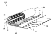
- the membrane separation device 110 of the present embodiment includes a central tube 41 and a laminate 42.
- the laminate 42 contains the separation membrane 10.
- the membrane separation device 110 is a spiral type membrane element.
- the central canal 41 has a cylindrical shape. On the surface of the central canal 41, a plurality of holes for allowing the permeated fluid 35 to flow into the central canal 41 are formed.
- the material of the central tube 41 include resins such as acrylonitrile / butadiene / styrene copolymer resin (ABS resin), polyphenylene ether resin (PPE resin), and polysulfon resin (PSF resin); metals such as stainless steel and titanium. Be done.
- the inner diameter of the central canal 41 is, for example, in the range of 20 to 100 mm.
- the laminated body 42 further includes a supply side flow path material 43 and a transmission side flow path material 44 in addition to the separation membrane 10.
- the laminate 42 is wound around the central canal 41.
- the membrane separation device 110 may further include an exterior material (not shown).
- a resin net made of polyphenylene sulfide (PPS) or ethylene-chlorotrifluoroethylene copolymer (ECTFE) can be used.
- Membrane separation using the membrane separation device 110 is performed by, for example, the following method.
- the space inside the central canal 41 is decompressed.
- the permeated fluid 35 that has passed through the separation membrane 10 of the laminated body 42 moves inside the central tube 41.
- the permeated fluid 35 is discharged to the outside through the central tube 41.
- the mixed liquid 30 (concentrated fluid 36) processed by the membrane separation device 110 is discharged to the outside from the other end of the wound laminate 42. As a result, water can be separated from the mixed liquid 30.
- Example 1 First, 1.54 g of zirconium chloride (ZrCl 4 : manufactured by Nacalai Tesque) and 1.21 g of 2-aminoterephthalic acid (manufactured by Tokyo Chemical Industry Co., Ltd.) were dissolved in 68.8 mL of DMF (manufactured by Nacalai Tesque). To the obtained solution, 0.66 mL of concentrated hydrochloric acid (manufactured by Nacalai Tesque, Inc.) was added, and the mixture was thoroughly stirred. Next, the solution was set in an autoclave (100 mL) and crystallized by a solvothermal method (100 ° C., 24 hours).
- ZrCl 4 manufactured by Nacalai Tesque
- 2-aminoterephthalic acid manufactured by Tokyo Chemical Industry Co., Ltd.
- the produced powder was allowed to cool to room temperature (25 ° C.) and then separated by a centrifuge (6000 rpm). The unreacted raw material was removed from the powder by washing the powder with methanol three times. The obtained yellow powder was added to 100 mL of methanol and stirred overnight. The powder was separated by a centrifuge (6000 rpm) and dried at 70 ° C. As a result, the metal-organic framework of Example 1 (UiO-66 (Zr) -NH 2 ) was obtained.
- Example 1 The structure of the metal-organic framework of Example 1 was analyzed by 1 H-NMR measurement and X-ray diffraction (XRD) measurement.
- XRD X-ray diffraction
- the zeta potential in DMF was measured by the following method. First, 5 mg of the metal-organic framework was added to 30 mL of DMF to prepare a suspension. The suspension was subjected to sonication (20 min) to uniformly disperse the metal-organic framework in DMF. For this suspension, the zeta potential was measured three times using a zeta potential / particle size measurement system (ELSZ-DN2 manufactured by Otsuka Electronics Co., Ltd.), and the average value was used as the zeta potential of the metal-organic framework in DMF. Identified.
- ELSZ-DN2 zeta potential / particle size measurement system
- the separation membrane was prepared by the following method.
- tetracarboxylic acid dianhydride bis (1,3-dioxo-1,3-dihydroisobenzofuran-5-carboxylic acid) ethylene (in the formula (4), A is the linking group 18 and R Compounds in which 1 to R 6 are hydrogen atoms) were prepared.
- diamine compounds 4,4'-diaminodiphenyl ether (in formula (5), B is a linking group 21 and Ar 1 and Ar 2 are p-phenylene groups) and 3,5-diaminobenzoic acid. Prepared.
- the diamine compound was dissolved in N-methyl-2-pyrrolidone to obtain a solution.
- Polyamic acid was obtained by adding tetracarboxylic dianhydride to the obtained solution under room temperature conditions.
- a polyimide was obtained by chemically imidizing the polyamic acid with triethylamine and acetic anhydride. Chemical imidization was performed in N-methyl-2-pyrrolidone under the condition of 60 ° C.
- the ratio of the structural unit derived from 3,5-diaminobenzoic acid to all the structural units derived from the diamine compound was 10 mol%.
- the polyimide was dissolved in 1,3-dioxolane to obtain a solution.
- a polyimide solution was added to the dispersion liquid containing the metal-organic framework of Example 1.
- a coating film was obtained by applying the obtained mixed solution onto a porous support.
- a UF membrane (ultrafiltration membrane) RS-50 (a laminate of a PVDF porous layer and a PET non-woven fabric) manufactured by Nitto Denko Corporation was used.
- the coating film was formed on the PVDF porous layer of RS-50.
- the separation functional layer was formed by drying the coating film.
- the content of the metal-organic framework in the separating functional layer was 5 wt%. As a result, a separation membrane for character evaluation was obtained.
- the separation coefficient ⁇ of the separation membrane and the flux of water that permeated the separation membrane were measured by the following method.
- the separation membrane was set in the metal cell and sealed with an O-ring to prevent leakage.
- 250 mL of the mixed liquid was injected into the metal cell so that the mixed liquid was in contact with the main surface of the separation membrane on the separation function layer side.
- the mixed liquid consisted substantially of ethanol and water.
- the concentration of ethanol in the mixed liquid was 50 vol% when the temperature of the mixed liquid was measured at 20 ° C.
- the metal cell was heated to 60 ° C. by a hot water bath.
- the space in the metal cell adjacent to the main surface of the separation membrane on the porous support side was depressurized. At this time, the pressure in this space was reduced so that the pressure in the space was 100 kPa smaller than the atmospheric pressure in the measurement environment. As a result, a gas permeation fluid was obtained.
- the permeated fluid was liquefied by cooling the permeated fluid of the gas with liquid nitrogen at -196 ° C.
- the composition of the liquid permeation fluid was analyzed using gas chromatography.
- the separation coefficient ⁇ of the separation membrane and the flux F of water permeating the separation membrane were calculated based on the composition of the permeated fluid, the weight of the permeated fluid, and the like.
- Example 2 0.5 g of the metal-organic framework (UiO-66 (Zr) -NH 2 ) of Example 1 and 0.5 g of 2-hydroxyterephthalic acid (manufactured by Tokyo Chemical Industry Co., Ltd.) were added to 33 mL of DMF, and the mixture was added to 33 mL of DMF for 10 minutes at room temperature. Stirred. The obtained suspension was heated to 120 ° C. and stirred for 5 minutes (0.08 hours). After allowing the suspension to cool to room temperature, the powder in the suspension was recovered by a centrifuge (6000 rpm). The obtained yellow powder was added to 100 mL of methanol and stirred overnight.
- the metal-organic framework (UiO-66 (Zr) -NH 2 ) of Example 1 0.5 g of the metal-organic framework (UiO-66 (Zr) -NH 2 ) of Example 1 and 0.5 g of 2-hydroxyterephthalic acid (manufactured by Tokyo Chemical Industry Co., Ltd.) were
- the powder was recovered by a centrifuge (6000 rpm) and dried at 70 ° C.
- the metal-organic framework of Example 2 (UiO-66 (Zr) -NH 2 , OH) was obtained.
- structural analysis, zeta potential measurement in DMF, and characteristic evaluation of the separation membrane were performed by the same method as in Example 1. Further, based on the result of 1 H-NMR measurement of the metal organic structure, the total value of the number of moles of the first functional group (amino group) and the number of moles of the second functional group (hydroxy group) in the metal organic structure. The ratio P1 of the number of moles of the second functional group to 2 was calculated.
- Example 3 The characteristics of the separation membrane were evaluated by the same method as in Example 2 except that the content of the metal-organic framework in the separation functional layer was changed to 10 wt%.
- Example 4 0.5 g of the metal-organic framework of Example 1 (UiO-66 (Zr) -NH 2 ) and 1.68 g of 2-nitroterephthalic acid (manufactured by Tokyo Chemical Industry Co., Ltd.) were added to 33 mL of DMF, and the mixture was added to 33 mL of DMF for 10 minutes at room temperature. Stirred. The obtained suspension was heated to 120 ° C. and stirred for 5 minutes (0.08 hours). After allowing the suspension to cool to room temperature, the powder in the suspension was recovered by a centrifuge (6000 rpm). The obtained yellow powder was added to 100 mL of methanol and stirred overnight.
- the powder was recovered by a centrifuge (6000 rpm) and dried at 70 ° C.
- the metal-organic framework of Example 4 (UiO-66 (Zr) -NH 2 , NO 2 ) was obtained.
- structural analysis, zeta potential measurement in DMF, and characteristic evaluation of the separation membrane were performed by the same method as in Example 1. Further, based on the result of 1 H-NMR measurement of the metal organic structure, the total value of the number of moles of the first functional group (amino group) and the number of moles of the second functional group (nitro group) in the metal organic structure. The ratio P1 of the number of moles of the second functional group to 2 was calculated.
- Example 5 0.5 g of the metal-organic framework of Example 1 (UiO-66 (Zr) -NH 2 ) and 0.58 g of trimellitic acid (manufactured by Nacalai Tesque) were added to 33 mL of DMF, and the mixture was stirred at room temperature for 10 minutes. The obtained suspension was heated to 120 ° C. and stirred for 5 minutes (0.08 hours). After allowing the suspension to cool to room temperature, the powder in the suspension was recovered by a centrifuge (6000 rpm). The obtained yellow powder was added to 100 mL of methanol and stirred overnight. The powder was recovered by a centrifuge (6000 rpm) and dried at 70 ° C.
- the metal-organic framework of Example 5 (UiO-66 (Zr) -NH 2 , COOH) was obtained.
- structural analysis, zeta potential measurement in DMF, and characteristic evaluation of the separation membrane were performed by the same method as in Example 1. Further, based on the result of 1 H-NMR measurement of the metal organic structure, the total value of the number of moles of the first functional group (amino group) and the number of moles of the second functional group (carboxyl group) in the metal organic structure. The ratio P1 of the number of moles of the second functional group to 2 was calculated.
- Example 6 The metal-organic framework of Example 6 (UiO-66 (Zr) -NH 2 , COOH) was obtained by the same method as in Example 5, except that the suspension heated to 120 ° C. was stirred for 24 hours.
- the metal-organic framework of Example 6 was structurally analyzed and the characteristics of the separation membrane were evaluated by the same method as in Example 1. Further, based on the result of 1 H-NMR measurement of the metal organic structure, the total value of the number of moles of the first functional group (amino group) and the number of moles of the second functional group (carboxyl group) in the metal organic structure. The ratio P1 of the number of moles of the second functional group to 2 was calculated.
- Example 7 zirconium oxynitrate (ZrO (NO 3) 2 ⁇ 2H 2 O: manufactured by Nacalai Tesque) was 1.80g and trimellitic acid 3.27g was added to a mixture of DMF54mL and 36.4g benzoic acid, by stirring These were dissolved. Next, the solution was set in an autoclave (100 mL) and crystallized by a solvothermal method (150 ° C., 24 hours). The produced powder was allowed to cool to room temperature and then separated by a centrifuge (6000 rpm). The unreacted raw material was removed from the powder by washing the powder with methanol three times.
- ZrO (NO 3) 2 ⁇ 2H 2 O: manufactured by Nacalai Tesque zirconium oxynitrate
- Example 7 the metal-organic framework of Example 7 (UiO-66 (Zr) -COOH) was obtained.
- structural analysis, zeta potential measurement in DMF, and characteristic evaluation of the separation membrane were performed by the same method as in Example 1.
- Example 8 0.5 g of the metal-organic framework of Example 1 (UiO-66 (Zr) -NH 2 ) and 1.25 g of terephthalic acid (manufactured by Nacalai Tesque) were added to 33 mL of DMF, and the mixture was stirred at room temperature for 10 minutes. The obtained suspension was heated to 120 ° C. and stirred for 5 minutes (0.08 hours). After allowing the suspension to cool to room temperature, the powder in the suspension was recovered by a centrifuge (6000 rpm). The obtained yellow powder was added to 100 mL of methanol and stirred overnight. The powder was recovered by a centrifuge (6000 rpm) and dried at 70 ° C.
- the metal-organic framework of Example 8 (UiO-66 (Zr) -NH 2 , H) was obtained.
- structural analysis, zeta potential measurement in DMF, and characteristic evaluation of the separation membrane were performed by the same method as in Example 1.
- the ratio of the number of moles of terephthalic acid to the total value of the number of moles of 2-aminoterephthalic acid and the number of moles of terephthalic acid in the metal-organic framework is calculated. Calculated.
- the metal-organic frameworks of Examples 2 to 5 containing a second functional group (hydroxy group, nitro group or carboxyl group) and having a ratio P1 adjusted to 30 mol% or less are other metal-organic frameworks. Compared with the structure, it was suitable for improving the flow flux F of the permeated fluid (water) permeating the separation membrane.
- the separation coefficient ⁇ of the separation membrane was 20 or more, which was a practically sufficient value.
- the thickness of the separation functional layer in the separation membrane for character evaluation was unified to 1 to 1.5 ⁇ m.
- the separation coefficient ⁇ of the separation membrane was 66.6, and the water flux F was 0.21 kg / m 2 / hr. ..
- the metal-organic framework of this embodiment is suitable as a filler for a separation membrane.
- This separation membrane is useful for separating water from a mixed liquid containing alcohol and water, especially for purification of bioethanol.
Landscapes
- Chemical & Material Sciences (AREA)
- Chemical Kinetics & Catalysis (AREA)
- Engineering & Computer Science (AREA)
- Organic Chemistry (AREA)
- Water Supply & Treatment (AREA)
- Dispersion Chemistry (AREA)
- Inorganic Chemistry (AREA)
- Manufacturing & Machinery (AREA)
- Separation Using Semi-Permeable Membranes (AREA)
- Organic Low-Molecular-Weight Compounds And Preparation Thereof (AREA)
Abstract
本発明は、分離膜を透過する透過流体の流束を向上させることに適した金属有機構造体を提供する。本発明の金属有機構造体は、金属イオン及び有機配位子を含む。有機配位子は、金属イオンに配位するための官能基以外に、第1官能基と、第1官能基とは異なる第2官能基とを含む。第2官能基は、ヒドロキシ基、ニトロ基又はカルボキシル基である。第1官能基のモル数と第2官能基のモル数との合計値に対する第2官能基のモル数の比率が30モル%以下である。
Description
本発明は、金属有機構造体、分離膜及び金属有機構造体の製造方法に関する。
金属有機構造体(Metal-Organic-Framework:MOF)は、内部に低分子化合物を取り込むことができる構造を有しており、触媒、医薬品、化粧品などの様々な用途で利用されている。金属有機構造体は、多孔性配位高分子(Porous Coordination Polymer:PCP)と呼ばれることもある。
金属有機構造体は、通常、金属イオン及び有機配位子から形成されている。有機配位子は、金属イオンに配位するための官能基を含んでおり、当該官能基によって金属イオンに配位している。従来の金属有機構造体は、例えば、特許文献1に開示されている。
本発明者らは、鋭意検討の結果、金属有機構造体を分離膜に添加した場合に、分離膜を透過する透過流体の流束が変化することを新たに見出した。
そこで本発明は、分離膜を透過する透過流体の流束を向上させることに適した金属有機構造体を提供することを目的とする。
本発明は、
金属イオン及び有機配位子を含み、
前記有機配位子は、前記金属イオンに配位するための官能基以外に、第1官能基と、前記第1官能基とは異なる第2官能基とを含み、
前記第2官能基は、ヒドロキシ基、ニトロ基又はカルボキシル基であり、
前記第1官能基のモル数と前記第2官能基のモル数との合計値に対する前記第2官能基の前記モル数の比率が30モル%以下である、金属有機構造体を提供する。
金属イオン及び有機配位子を含み、
前記有機配位子は、前記金属イオンに配位するための官能基以外に、第1官能基と、前記第1官能基とは異なる第2官能基とを含み、
前記第2官能基は、ヒドロキシ基、ニトロ基又はカルボキシル基であり、
前記第1官能基のモル数と前記第2官能基のモル数との合計値に対する前記第2官能基の前記モル数の比率が30モル%以下である、金属有機構造体を提供する。
さらに本発明は、
上記の金属有機構造体の製造方法であって、
前記金属イオンと、前記第1官能基を含む第1有機配位子とを含む前記金属有機構造体の前駆体を、前記第2官能基を含む第2有機配位子に接触させることを含む、製造方法を提供する。
上記の金属有機構造体の製造方法であって、
前記金属イオンと、前記第1官能基を含む第1有機配位子とを含む前記金属有機構造体の前駆体を、前記第2官能基を含む第2有機配位子に接触させることを含む、製造方法を提供する。
さらに本発明は、
金属有機構造体の製造方法であって、
前記金属有機構造体は、金属イオン及び有機配位子を含み、
前記有機配位子は、前記金属イオンに配位するための官能基以外に、第1官能基と、前記第1官能基とは異なる第2官能基とを含み、
前記第2官能基は、ヒドロキシ基、ニトロ基又はカルボキシル基であり、
前記製造方法は、
40℃以上の温度かつ5分以下の時間で、前記金属イオンと、前記第1官能基を含む第1有機配位子とを含む前記金属有機構造体の前駆体を、前記第2官能基を含む第2有機配位子に接触させることを含む、製造方法を提供する。
金属有機構造体の製造方法であって、
前記金属有機構造体は、金属イオン及び有機配位子を含み、
前記有機配位子は、前記金属イオンに配位するための官能基以外に、第1官能基と、前記第1官能基とは異なる第2官能基とを含み、
前記第2官能基は、ヒドロキシ基、ニトロ基又はカルボキシル基であり、
前記製造方法は、
40℃以上の温度かつ5分以下の時間で、前記金属イオンと、前記第1官能基を含む第1有機配位子とを含む前記金属有機構造体の前駆体を、前記第2官能基を含む第2有機配位子に接触させることを含む、製造方法を提供する。
本発明によれば、分離膜を透過する透過流体の流束を向上させることに適した金属有機構造体を提供できる。
本発明の一形態では、有機配位子は、第1官能基を含む第1有機配位子と、第2官能基を含む第2有機配位子とを含む。
本発明の一形態では、第1官能基がアミノ基である。
本発明の一形態では、有機配位子は、ジカルボン酸誘導体を含む。
本発明の一形態では、有機配位子は、テレフタル酸誘導体を含む。
本発明の一形態では、金属イオンは、ジルコニウムを含む。
本発明の一形態では、N,N-ジメチルホルムアミド中での金属有機構造体のゼータ電位が負の値である。
本発明の一形態では、分離膜は、上記の金属有機構造体を含む。
本発明の一形態では、分離膜は、マトリクスと当該マトリクスに分散した金属有機構造体とを含む分離機能層を備える。
本発明の一形態では、上記のマトリクスがポリイミドを含む。
本発明の一形態では、上記のポリイミドは、下記式(1)で表される構造単位を含む。

式(1)において、Aは、Fedors法による溶解度パラメータが5.0(cal/cm3)1/2より大きい連結基であり、Bは、Fedors法による溶解度パラメータが8.56(cal/cm3)1/2より大きい連結基であり、R1~R6は、互いに独立して、水素原子、ハロゲン原子、ヒドロキシ基、スルホン酸基、炭素数1~30のアルコキシ基、又は、炭素数1~30の炭化水素基であり、Ar1及びAr2は、2価の芳香族基である。ただし、Ar1及びAr2は、置換基を有していてもよいフェニレン基である場合には、下記式(2)で表される。

式(2)において、R7~R10は、互いに独立して、水素原子、ハロゲン原子、ヒドロキシ基、スルホン酸基、炭素数1~30のアルコキシ基、又は、炭素数1~30の炭化水素基である。
本発明の一形態では、分離機能層における金属有機構造体の含有率が10wt%以下である。
本発明の一形態では、分離膜は、アルコールと水とを含む混合液体から水を分離するために用いられる。
以下、本発明の詳細を説明するが、以下の説明は、本発明を特定の実施形態に制限する趣旨ではない。
(金属有機構造体の実施形態)
本実施形態の金属有機構造体Sは、金属イオン及び有機配位子を含む。有機配位子は、金属イオンに配位するための官能基以外に、第1官能基と、第1官能基とは異なる第2官能基とを含む。後述するとおり、金属有機構造体Sは、分離膜に添加して用いることができる。
本実施形態の金属有機構造体Sは、金属イオン及び有機配位子を含む。有機配位子は、金属イオンに配位するための官能基以外に、第1官能基と、第1官能基とは異なる第2官能基とを含む。後述するとおり、金属有機構造体Sは、分離膜に添加して用いることができる。
第1官能基は、例えば、分離膜を透過する透過流体との親和性が高い官能基である。一例として、分離膜がアルコールと水とを含む混合液体から水を分離するために用いられる場合、第1官能基は、第2官能基以外の極性基、特に親水性基、であることが好ましい。第1官能基の具体例は、アミノ基(特に1級アミノ基)である。アミノ基を含む有機配位子を備えた金属有機構造体Sは、耐久性に優れる傾向がある。
第2官能基は、ヒドロキシ基、ニトロ基又はカルボキシル基であり、好ましくはカルボキシル基である。第2官能基は、分離膜、特にポリイミドを含む分離膜、の内部での金属有機構造体Sの分散性を向上させる傾向がある。
本実施形態では、第1官能基のモル数と第2官能基のモル数との合計値に対する第2官能基のモル数の比率P1が30モル%以下であり、好ましくは25モル%以下であり、より好ましくは20モル%以下であり、さらに好ましくは15モル%以下である。比率P1は、好ましくは1モル%以上であり、より好ましくは3モル%以上である。
金属イオンに配位するための官能基は、特に限定されず、例えばカルボキシル基である。有機配位子は、金属イオンに配位するための官能基として2つのカルボキシル基を含んでいてもよい。すなわち、有機配位子は、第1官能基及び第2官能基を含むジカルボン酸誘導体を含んでいてもよく、第1官能基及び第2官能基を含むテレフタル酸誘導体を含んでいてもよい。金属イオンは、特に限定されず、例えば遷移金属を含み、好ましくはジルコニウムを含む。
有機配位子は、第1官能基を含む第1有機配位子と、第2官能基を含む第2有機配位子とを含んでいてもよい。第1有機配位子は、詳細には、第1官能基と、金属イオンに配位するための官能基とを含む炭化水素化合物であり、好ましくは第1官能基を含むジカルボン酸誘導体である。第1有機配位子の炭素数は、特に限定されず、例えば3~25であり、好ましくは3~10である。第1有機配位子は、芳香環を含んでいてもよい。第1有機配位子において、芳香環は、炭素原子から構成されていることが好ましい。ただし、芳香環は、酸素原子、窒素原子、硫黄原子などのヘテロ原子を含む複素芳香環であってもよい。芳香環は、多環式であってもよいが、単環式であることが好ましい。芳香環は、例えば、ベンゼン環である。
第1有機配位子は、第1官能基を含むテレフタル酸誘導体であることが好ましい。このような第1有機配位子は、例えば、下記式(6)で表される。なお、式(6)において、Xは、第1官能基である。

第1有機配位子の具体例は、2-アミノテレフタル酸である。
第2有機配位子は、詳細には、第2官能基と、金属イオンに配位するための官能基とを含む炭化水素化合物であり、好ましくは第2官能基を含むジカルボン酸誘導体である。第2有機配位子は、第1官能基の代わりに第2官能基を含むことを除き、第1有機配位子と同じであってもよい。第2有機配位子の炭素数は、特に限定されず、例えば3~25であり、好ましくは3~10である。第2有機配位子は、芳香環を含んでいてもよい。第2有機配位子において、芳香環は、炭素原子から構成されていることが好ましい。ただし、芳香環は、酸素原子、窒素原子、硫黄原子などのヘテロ原子を含む複素芳香環であってもよい。芳香環は、多環式であってもよいが、単環式であることが好ましい。芳香環は、例えば、ベンゼン環である。
第2有機配位子は、第2官能基を含むテレフタル酸誘導体であることが好ましい。このような第2有機配位子は、例えば、下記式(7)で表される。なお、式(7)において、Yは、第2官能基である。

第2有機配位子の具体例は、2-ヒドロキシテレフタル酸、2-ニトロテレフタル酸、トリメリット酸などである。
本実施形態では、第1有機配位子のモル数と第2有機配位子のモル数との合計値に対する第2有機配位子のモル数の比率P2が30モル%以下であり、好ましくは25モル%以下であり、より好ましくは20モル%以下であり、さらに好ましくは15モル%以下である。比率P2は、好ましくは1モル%以上であり、より好ましくは3モル%以上である。
金属有機構造体Sは、例えば、下記式(8)で表される。式(8)は、式(6)で表される第1有機配位子、式(7)で表される第2有機配位子及びジルコニウムイオンから構成されたUiO-66誘導体を簡略的に示している。

金属有機構造体Sの製造方法は、例えば、金属イオンと第1有機配位子とを含む金属有機構造体Sの前駆体を第2有機配位子に接触させることを含む。金属有機構造体Sの前駆体は、例えば、下記式(9)で表される。式(9)は、式(6)で表される第1有機配位子及びジルコニウムイオンから構成されたUiO-66誘導体を簡略的に示している。

金属有機構造体Sの前駆体を第2有機配位子に接触させると、前駆体に含まれる一部の第1有機配位子が第2有機配位子と置き換わる。これにより、金属有機構造体Sが得られる。このように、有機配位子を交換させることによって金属有機構造体を作製する方法は、Post synthetic exchange(PSE)法として知られている。PSE法によれば、金属有機構造体Sの前駆体に含まれる第1有機配位子のうち、前駆体の外部に近い位置に存在する第1有機配位子から第2有機配位子に置き換わる傾向がある。そのため、得られた金属有機構造体Sにおいて、第1有機配位子及び第2有機配位子は偏って存在する。詳細には、金属有機構造体Sにおける第1有機配位子の含有率は、金属有機構造体Sの内部から外部に向かって徐々に減少する傾向がある。一方、金属有機構造体Sにおける第2有機配位子の含有率は、金属有機構造体Sの内部から外部に向かって徐々に増加する傾向がある。
金属有機構造体Sの前駆体を第2有機配位子に接触させる方法は、特に限定されない。例えば、N,N-ジメチルホルムアミド(DMF)などの有機溶媒に、金属有機構造体Sの前駆体と第2有機配位子とを添加することによって、前駆体を第2有機配位子に接触させてもよい。このとき、混合液における金属有機構造体Sの前駆体の濃度は、特に限定されず、例えば0.1wt%~20wt%である。混合液における第2有機配位子の濃度は、特に限定されず、例えば0.1wt%~20wt%である。前駆体を第2有機配位子に接触させた状態で、これらについて加熱を行ってもよい。加熱温度は、前駆体及び第2有機配位子に応じて適宜設定することができ、例えば30℃~150℃である。加熱時間は、例えば0.01時間~24時間であり、好ましくは1時間以下である。特に、金属有機構造体Sの前駆体と第2有機配位子との接触は、40℃以上の温度かつ5分以下の時間で行うことが好ましい。
すなわち、本発明は、その別の側面から、
金属有機構造体Sの製造方法であって、
金属有機構造体Sは、金属イオン及び有機配位子を含み、
有機配位子は、金属イオンに配位するための官能基以外に、第1官能基と、第1官能基とは異なる第2官能基とを含み、
第2官能基は、ヒドロキシ基、ニトロ基又はカルボキシル基であり、
当該製造方法は、
40℃以上の温度かつ5分以下の時間で、金属イオンと、第1官能基を含む第1有機配位子とを含む金属有機構造体Sの前駆体を、第2官能基を含む第2有機配位子に接触させることを含む、製造方法を提供する。
金属有機構造体Sの製造方法であって、
金属有機構造体Sは、金属イオン及び有機配位子を含み、
有機配位子は、金属イオンに配位するための官能基以外に、第1官能基と、第1官能基とは異なる第2官能基とを含み、
第2官能基は、ヒドロキシ基、ニトロ基又はカルボキシル基であり、
当該製造方法は、
40℃以上の温度かつ5分以下の時間で、金属イオンと、第1官能基を含む第1有機配位子とを含む金属有機構造体Sの前駆体を、第2官能基を含む第2有機配位子に接触させることを含む、製造方法を提供する。
金属有機構造体Sの前駆体は、公知の方法によって作製することができる。例えば、金属塩及び第1有機配位子をDMFやN,N-ジメチルアセトアミド(DMA)などの有機溶媒に溶解させる。金属塩としては、塩化ジルコニウム、オキシ硝酸ジルコニウム、オキシ塩化ジルコニウムなどが挙げられる。次に、得られた溶液に酸を添加する。酸としては、例えば、塩酸などの無機酸;ギ酸、安息香酸などの有機酸が挙げられる。次に、溶液をオートクレーブにセットし、ソルボサーマル法を行う。これにより、金属有機構造体Sの前駆体が得られる。
金属有機構造体Sは、第2官能基に起因して、分離膜中、特にポリイミド中、での分散性に優れている。金属有機構造体Sのポリイミド中での分散性は、例えば、N,N-ジメチルホルムアミド(DMF)中での金属有機構造体Sのゼータ電位によって評価することができる。DMFは、ポリイミドとハンセン溶解度パラメータの距離が比較的小さい化合物である。そのため、DMF中の金属有機構造体Sは、ポリイミド中での金属有機構造体Sの挙動と同様の挙動を示す傾向がある。
DMF中での金属有機構造体Sのゼータ電位は、例えば負の値であり、好ましくは-1mV~-15mVである。金属有機構造体Sのゼータ電位は、市販のゼータ電位測定装置により測定できる。DMF中でのゼータ電位が負の値である金属有機構造体Sは、ポリイミド中で凝集しにくい傾向がある。分離膜中での凝集が抑制された金属有機構造体Sは、分離膜を透過する透過流体の流束を向上させることに適している。
金属有機構造体Sは、例えば、水を吸着することができる。特に、金属有機構造体Sは、エタノールよりも水を吸着しやすいことが好ましい。25℃、7.4kPaのエタノール雰囲気下での金属有機構造体Sへのエタノールの吸着量Q1に対する、25℃、3.2kPaの水蒸気下での金属有機構造体Sへの水の吸着量Q2の比R1は、例えば2.0以上であり、好ましくは3.0以上である。比R1の上限値は、特に限定されず、例えば5.0である。なお、本明細書において、「吸着量」は、1gの金属有機構造体Sが吸着した気体の体積を標準状態(298K、1atm)に換算した値を意味する。
金属有機構造体Sへのエタノールの吸着量Q1は、次の方法によって特定することができる。まず、金属有機構造体Sを減圧雰囲気下で加熱することによって前処理を行う。前処理は、真空雰囲気下で行ってもよい。前処理の温度は、例えば100℃以上である。前処理の時間は、特に限定されず、例えば1時間以上である。次に、マイクロトラックベル社製のBELSORP-maxIIなどの公知の蒸気吸着量測定装置に金属有機構造体Sをセットする。次に、25℃の測定温度で、気体のエタノールを測定装置内に導入する。導入された気体のエタノールは、金属有機構造体Sに吸着される。気体のエタノールの導入は、測定装置内におけるエタノールの圧力が7.4kPaに達するまで行う。7.4kPaは、25℃におけるエタノールの平衡蒸気圧(飽和蒸気圧)に相当する。金属有機構造体Sによるエタノールの吸着が平衡状態に達したことを確認した後に、金属有機構造体Sによるエタノールの吸着量を特定する。金属有機構造体Sによるエタノールの吸着が平衡状態に達したことは、測定装置内におけるエタノールの圧力の変化によって判断することができる。例えば、測定装置内におけるエタノールの圧力の変化が500秒間で40Pa以下である場合に、金属有機構造体Sによるエタノールの吸着が平衡状態に達したと判断することができる。上記の方法によって特定されたエタノールの吸着量を吸着量Q1とみなすことができる。
金属有機構造体Sへの水の吸着量Q2は、次の方法によって特定することができる。まず、金属有機構造体Sに対して、上述した前処理を行う。この金属有機構造体Sを蒸気吸着量測定装置にセットする。次に、25℃の測定温度で、水蒸気を測定装置内に導入する。水蒸気の導入は、測定装置内における水蒸気の圧力が3.2kPaに達するまで行う。3.2kPaは、25℃における水の平衡蒸気圧に相当する。金属有機構造体Sによる水の吸着が平衡状態に達したことを確認した後に、金属有機構造体Sによる水の吸着量を特定する。特定された水の吸着量を吸着量Q2とみなすことができる。
金属有機構造体Sへのエタノールの吸着量Q1は、例えば200cm3/g以下である。吸着量Q1の下限値は、特に限定されず、90cm3/gであってもよく、100cm3/gであってもよい。金属有機構造体Sへの水の吸着量Q2は、例えば300cm3/g以上であり、場合によっては350cm3/g以上であってもよく、450cm3/g以上であってもよく、500cm3/g以上であってもよく、550cm3/g以上であってもよい。吸着量Q2の上限値は、特に限定されず、例えば800cm3/gである。
金属有機構造体Sは、窒素ガス吸着によるBET(Brunauer-Emmett-Teller)比表面積S1に対する水蒸気吸着によるBET比表面積S2の比R2が0.005以上であってもよい。金属有機構造体Sにおいて、比R2は、例えば0.01以上であり、好ましくは0.1以上であり、より好ましくは0.2以上であり、さらに好ましくは0.3以上である。比R2は、25以下であってもよく、10以下であってもよく、1.0以下であってもよく、0.6以下であってもよい。
金属有機構造体Sにおいて、窒素ガス吸着によるBET比表面積S1は、例えば1500m2/g以下であり、好ましくは1000m2/g以下であり、場合によっては900m2/g以下であってもよい。比表面積S1は、30m2/g以上であってもよく、400m2/g以上であってもよい。金属有機構造体Sにおいて、水蒸気吸着によるBET比表面積S2は、例えば10m2/g以上であり、好ましくは100m2/g以上であり、より好ましくは150m2/g以上であり、場合によっては200m2/g以上であってもよい。比表面積S2は、1000m2/g以下であってもよく、600m2/g以下であってもよく、400m2/g以下であってもよい。
(分離膜の実施形態)
図1に示すように、本実施形態の分離膜10は、分離機能層1を備えている。分離機能層1は、例えば、混合液体に含まれる水を優先的又は選択的に透過させることができる。分離膜10は、分離機能層1を支持している多孔性支持体2をさらに備えていてもよい。
図1に示すように、本実施形態の分離膜10は、分離機能層1を備えている。分離機能層1は、例えば、混合液体に含まれる水を優先的又は選択的に透過させることができる。分離膜10は、分離機能層1を支持している多孔性支持体2をさらに備えていてもよい。
分離機能層1は、例えば、フィラー3及びマトリクス4を有する。フィラー3は、マトリクス4に分散し、マトリクス4内に埋め込まれている。図1に示した形態では、全てのフィラー3が互いに離間している。ただし、フィラー3は、部分的に凝集していてもよい。
フィラー3は、上述した金属有機構造体Sを含み、例えば、金属有機構造体Sを主成分として含む。本明細書において、「主成分」は、フィラー3に重量基準で最も多く含まれる成分を意味する。フィラー3における金属有機構造体Sの含有率は、例えば50wt%以上であり、好ましくは80wt%以上であり、より好ましくは95%以上である。フィラー3は、例えば、実質的に金属有機構造体Sからなる。ただし、フィラー3は、金属有機構造体S以外の他の成分を含んでいてもよい。
分離機能層1における金属有機構造体Sの含有率は、例えば1wt%以上であり、好ましくは3wt%以上であり、より好ましくは5wt%以上である。金属有機構造体Sの含有率は、例えば30wt%以下であり、好ましくは10wt%以下である。金属有機構造体Sの含有率が10wt%以下である分離機能層1は、高い分離性能を有する傾向がある。
フィラー3の形状は、特に限定されず、例えば粒子状である。本明細書において、「粒子状」は、球状、楕円体状、鱗片状、繊維状などを含む。フィラー3の平均粒径は、特に限定されず、例えば5nm~10000nmである。フィラー3の平均粒径は、例えば、次の方法によって特定することができる。まず、分離機能層1の断面を透過電子顕微鏡で観察する。得られた電子顕微鏡像において、特定のフィラー3の面積を画像処理によって算出する。算出された面積と同じ面積を有する円の直径をその特定のフィラー3の粒径(粒子の直径)とみなす。任意の個数(少なくとも50個)のフィラー3の粒径をそれぞれ算出し、算出値の平均値をフィラー3の平均粒径とみなす。
マトリクス4は、ポリイミドを含むことが好ましい。マトリクス4に含まれるポリイミドとしては、例えば、下記式(1)で表される構造単位を含むポリイミド(P)が挙げられる。

式(1)において、Aは、例えば、Fedors法による溶解度パラメータが5.0(cal/cm3)1/2より大きい連結基である。本明細書では、「Fedors法による溶解度パラメータ」をSP値と呼ぶことがある。「Fedors法による溶解度パラメータ」は、次の式から算出することができる。ただし、次の式において、δiは、i成分の原子又は原子団のSP値である。Δeiは、i成分の原子又は原子団の蒸発エネルギーである。Δviは、i成分の原子又は原子団のモル体積である。
δi[(cal/cm3)1/2]=(Δei/Δvi)1/2
δi[(cal/cm3)1/2]=(Δei/Δvi)1/2
「Fedors法による溶解度パラメータ」の詳細は、例えば、Robert F. Fedors著、「Polymer Engineering and Science」、1974年、第14巻、第2号、P.147-154に開示されている。
AのSP値が5.0(cal/cm3)1/2より大きい場合、分離機能層1に対して水が容易に浸透する傾向がある。AのSP値は、好ましくは8.5(cal/cm3)1/2以上であり、より好ましくは11.0(cal/cm3)1/2以上であり、さらに好ましくは12.0(cal/cm3)1/2以上である。AのSP値の上限値は、特に限定されないが、例えば、30.0(cal/cm3)1/2であってもよい。AのSP値の好ましい例は、12.0(cal/cm3)1/2、12.68(cal/cm3)1/2等である。
Aは、例えば、酸素原子、窒素原子、硫黄原子及びケイ素原子からなる群より選ばれる少なくとも1つを含み、好ましくは酸素原子及び窒素原子からなる群より選ばれる少なくとも1つを含み、特に好ましくは酸素原子を含む。Aは、例えば、エーテル基、エステル基、ケトン基、ヒドロキシ基、アミド基、チオエーテル基及びスルホニル基からなる群より選ばれる少なくとも1つの官能基を含み、好ましくはエーテル基及びエステル基からなる群より選ばれる少なくとも1つを含む。
Aは、上記の官能基と共にその他の基、例えば炭化水素基を含んでいてもよい。炭化水素基の炭素数は、特に制限されないが、例えば1~15である。この炭素数は、1~3であってもよく、6~15であってもよい。炭化水素基の価数にも制限はないが、好ましくは2価の炭化水素基である。2価の炭化水素基としては、例えば、メチレン基、エチレン基、プロパン-1,3-ジイル基、プロパン-2,2-ジイル基、ブタン-1,4-ジイル基、ペンタン-1,5-ジイル基、2,2-ジメチルプロパン-1,3-ジイル基、1,4-フェニレン基、2,5-ジ-tert-ブチル-1,4-フェニレン基、1-メチル-1,1-エタンジイルビス(1,4-フェニレン)基及びビフェニル-4,4’-ジイル基が挙げられる。さらに、これらの炭化水素基に含まれる少なくとも1つの水素原子は、ハロゲン原子によって置換されていてもよい。
Aは、例えば、一般式-O-R19-O-、又は、一般式-COO-R20-OOC-で表される連結基である。ここで、R19及びR20は、炭素数1~15の2価の炭化水素基である。2価の炭化水素基としては、上述したものが挙げられる。
Aは、上述の官能基を含んでいなくてもよい。このようなAとしては、例えば、アルキレン基が挙げられる。アルキレン基の炭素数は、特に制限されないが、例えば1~15であってもよく、1~5であってもよい。アルキレン基は、分岐鎖状であってもよいが、直鎖状であることが好ましい。アルキレン基は、その水素原子の一部がハロゲン原子によって置換されていてもよいが、置換されていない状態、すなわち、直鎖の又は分岐を有するアルキレン基そのものであることが好ましい。
式(1)において、Aによって連結している2つのフタルイミド構造を結ぶ結合鎖のうち、原子の数が最も少ない結合鎖を構成する原子の数は、例えば2以上であり、好ましくは4以上であり、より好ましくは6~11である。本明細書では、原子の数が最も少ない結合鎖を「最短の結合鎖」と呼ぶことがある。一例として、Aがo-フェニレン基である場合、Aによって連結している2つのフタルイミド構造を結ぶ最短の結合鎖を構成する原子の数は2である。Aがp-フェニレン基である場合、Aによって連結している2つのフタルイミド構造を結ぶ最短の結合鎖を構成する原子の数は4である。
Aは、以下の表1及び2に示された連結基1~26のうちの1つであってもよい。表1及び2には、連結基1~26について、化学構造、SP値、及び、最短の結合鎖を構成する原子の数も示されている。Aは、好ましくは連結基11又は連結基18であり、特に好ましくは連結基18である。Aが連結基11又は連結基18であるとき、ポリイミド(P)は、N-メチル-2-ピロリドン(NMP)、1,3-ジオキソランなどの極性有機溶媒に溶解しやすく、分離機能層1の望ましい製造方法を適用しやすい。


式(1)において、Bは、例えば、SP値が8.56(cal/cm3)1/2より大きい連結基である。BのSP値が8.56(cal/cm3)1/2より大きい場合、分離機能層1に対して水が容易に浸透する傾向がある。BのSP値は、好ましくは9.0(cal/cm3)1/2以上であり、より好ましくは11.0(cal/cm3)1/2以上であり、さらに好ましくは12.0(cal/cm3)1/2以上であり、特に好ましくは14.0(cal/cm3)1/2以上である。BのSP値の上限値は、特に限定されないが、例えば、30.0(cal/cm3)1/2であってもよい。BのSP値の好ましい例は、14.0(cal/cm3)1/2、14.51(cal/cm3)1/2等である。
Bは、例えば、酸素原子、窒素原子、硫黄原子及びケイ素原子からなる群より選ばれる少なくとも1つを含み、好ましくは酸素原子及び窒素原子からなる群より選ばれる少なくとも1つを含み、特に好ましくは酸素原子を含む。Bは、例えば、エーテル基、エステル基、ケトン基、ヒドロキシ基、アミド基、チオエーテル基及びスルホニル基からなる群より選ばれる少なくとも1つの官能基を含み、好ましくはエーテル基を含む。
Bは、上記の官能基と共にその他の基、例えば炭化水素基を含んでいてもよい。炭化水素基としては、Aについて上述したものが挙げられる。Bは、Aと同じであってもよく、異なっていてもよい。
式(1)において、Bによって連結しているAr1とAr2とを結ぶ結合鎖のうち、原子の数が最も少ない結合鎖(最短の結合鎖)を構成する原子の数は、例えば1以上である。最短の結合鎖を構成する原子の数の上限値は、特に限定されないが、例えば12である。最短の結合鎖を構成する原子の数は、好ましくは1である。
Bは、上記の表1及び2に示された連結基5~26のうちの1つであってもよい。Bは、好ましくは連結基9、連結基16又は連結基21であり、特に好ましくは連結基21である。
式(1)において、R1~R6は、互いに独立して、水素原子、ハロゲン原子、ヒドロキシ基、スルホン酸基、炭素数1~30のアルコキシ基、又は、炭素数1~30の炭化水素基である。R1~R6は、好ましくは水素原子である。R1~R6のアルコキシ基又は炭化水素基は、直鎖状、分岐鎖状のいずれであってもよい。アルコキシ基又は炭化水素基の炭素数は、好ましくは1~20であり、より好ましくは1~10であり、特に好ましくは1~5である。アルコキシ基としては、メトキシ基、エトキシ基、プロポキシ基などが挙げられる。炭化水素基としては、メチル基、エチル基、プロピル基などが挙げられる。アルコキシ基又は炭化水素基に含まれる少なくとも1つの水素原子は、ハロゲン原子によって置換されていてもよい。
R2及びR3、並びに、R5及びR6は、互いに結合して環構造を形成していてもよい。環構造は、例えば、ベンゼン環である。
式(1)において、Ar1及びAr2は、2価の芳香族基である。2価の芳香族基は、芳香環を含む。式(1)において、フタルイミド構造の窒素原子は、Ar1に含まれる芳香環、又は、Ar2に含まれる芳香環と直接結合していることが好ましい。式(1)において、Bは、Ar1に含まれる芳香環、及び、Ar2に含まれる芳香環のそれぞれと直接結合していてもよい。
Ar1及びAr2において、芳香環は、炭素原子から構成されていることが好ましい。ただし、芳香環は、酸素原子、窒素原子、硫黄原子などのヘテロ原子を含む複素芳香環であってもよい。芳香環は、多環式であってもよいが、単環式であることが好ましい。芳香環の炭素数は、特に限定されないが、例えば4~14であってもよく、6~10であってもよい。芳香環としては、例えば、ベンゼン環、ナフタレン環、アントラセン環、フェナントレン環、フラン環、ピロール環、ピリジン環及びチオフェン環が挙げられる。
Ar1及びAr2において、芳香環は、置換基を有していなくてもよく、置換基を有していてもよい。芳香環の置換基としては、例えば、ハロゲン原子、ヒドロキシ基、スルホン酸基、炭素数1~30のアルコキシ基、及び、炭素数1~30の炭化水素基が挙げられる。アルコキシ基及び炭化水素基としては、R1~R6について上述したものが挙げられる。芳香環が複数の置換基を有するとき、複数の置換基は、互いに同じであってもよく、異なっていてもよい。
Ar1及びAr2は、置換基を有していてもよいフェニレン基、又は、置換基を有していてもよいナフタレンジイル基であることが好ましい。Ar1及びAr2は、置換基を有していてもよいフェニレン基である場合、下記式(2)で表されてもよい。

式(2)において、R7~R10は、互いに独立して、水素原子、ハロゲン原子、ヒドロキシ基、スルホン酸基、炭素数1~30のアルコキシ基、又は、炭素数1~30の炭化水素基である。アルコキシ基及び炭化水素基としては、R1~R6について上述したものが挙げられる。R7~R10は、好ましくは水素原子である。式(2)は、p-フェニレン構造を示している。p-フェニレン構造を有するポリイミドは、o-フェニレン構造又はm-フェニレン構造を有するポリイミドに比べて、立体的に嵩高くなく、分離膜の分離性能を向上させることに適している。
Ar1及びAr2において、置換基を有していてもよいナフタレンジイル基は、例えば、ナフタレン-2,6-ジイル構造、ナフタレン-1,4-ジイル構造、ナフタレン-1,5-ジイル構造又はナフタレン-1,8-ジイル構造を有している。置換基を有していてもよいナフタレンジイル基は、例えば、ナフタレン-2,6-ジイル基である。
Ar1とAr2とは、同じであってもよく、異なっていてもよい。一例として、Ar1がナフタレン-2,6-ジイル基であり、かつ、Ar2がp-フェニレン基であってもよい。
ポリイミド(P)において、式(1)で表される構造単位は、好ましくは下記式(3)で表される構造単位である。

式(3)において、A、B及びR1~R6は、式(1)について上述したものと同じである。R11~R18は、互いに独立して、水素原子、ハロゲン原子、ヒドロキシ基、スルホン酸基、炭素数1~30のアルコキシ基、又は、炭素数1~30の炭化水素基である。アルコキシ基及び炭化水素基としては、R1~R6について上述したものが挙げられる。R11~R18は、好ましくは水素原子である。
ポリイミド(P)における式(1)で表される構造単位の含有率は、例えば50mol%以上であり、好ましくは60mol%以上であり、より好ましくは70mol%以上であり、さらに好ましくは80mol%以上であり、特に好ましくは90mol%以上である。式(1)で表される構造単位の含有率は、100mol%であってもよい。
式(1)で表される構造単位は、下記式(4)で表されるテトラカルボン酸二無水物(C)と下記式(5)で表されるジアミン化合物(D)との反応によって得ることができる。式(4)において、A及びR1~R6は、式(1)と同じである。式(5)において、B、Ar1及びAr2は、式(1)と同じである。


ポリイミド(P)は、テトラカルボン酸二無水物(C)とは異なる他のテトラカルボン酸二無水物に由来する構造単位を含んでいてもよい。他のテトラカルボン酸二無水物は、特に限定されず、公知のものを用いることができる。他のテトラカルボン酸二無水物としては、ピロメリット酸二無水物、4,4’-(ヘキサフルオロイソプロピリデン)ジフタル酸無水物などが挙げられる。
ポリイミド(P)において、テトラカルボン酸二無水物に由来する全ての構造単位に対するテトラカルボン酸二無水物(C)に由来する構造単位の比率p1は、例えば50mol%以上であり、好ましくは70mol%以上であり、より好ましくは90mol%以上である。比率p1は、100mol%であってもよい。
ポリイミド(P)は、ジアミン化合物(D)とは異なる他のジアミン化合物に由来する構造単位を含んでいてもよい。他のジアミン化合物は、特に限定されず、公知のものを用いることができる。他のジアミン化合物としては、フェニレンジアミン、ジアミノ安息香酸、ジアミノビフェニル、ジアミノジフェニルメタンなどが挙げられる。一例として、ポリイミド(P)は、ジアミノ安息香酸(例えば、3,5-ジアミノ安息香酸)に由来する構造単位を含んでいてもよい。ジアミノ安息香酸に由来する構造単位を含むポリイミド(P)は、分離膜10を透過する水の流束を増加させることに適している。
ポリイミド(P)において、ジアミン化合物に由来する全ての構造単位に対するジアミン化合物(D)に由来する構造単位の比率p2は、例えば50mol%以上であり、好ましくは70mol%以上であり、より好ましくは90mol%以上である。比率p2は、100mol%であってもよい。
ポリイミド(P)は、例えば、次の方法によって作製することができる。まず、ジアミン化合物(D)を溶媒に溶解させ、溶液を得る。溶媒としては、例えば、N-メチル-2-ピロリドン(NMP)、1,3-ジオキソランなどの極性有機溶媒が挙げられる。次に、得られた溶液に、テトラカルボン酸二無水物(C)を徐々に添加する。これにより、テトラカルボン酸二無水物(C)及びジアミン化合物(D)が反応し、ポリアミド酸が形成される。テトラカルボン酸二無水物(C)の添加は、例えば、室温(25℃)以下の温度で3~20時間、撹拌条件下で行われる。
次に、ポリアミド酸をイミド化することによって、ポリイミド(P)を得ることができる。イミド化の方法としては、例えば、化学イミド化法及び熱イミド化法が挙げられる。化学イミド化法は、脱水縮合剤を用いてポリアミド酸をイミド化する方法である。化学イミド化法は、室温条件で行われてもよく、加熱条件で行われてもよい。脱水縮合剤としては、例えば、無水酢酸、ピリジン及びトリエチルアミンが挙げられる。熱イミド化法は、加熱処理によって、ポリアミド酸をイミド化する方法である。加熱処理の温度は、例えば、180℃以上である。
マトリクス4におけるポリイミド(P)の含有率は、例えば50wt%以上であり、好ましくは60wt%以上であり、より好ましくは70wt%以上であり、さらに好ましくは80wt%以上であり、特に好ましくは90wt%以上である。マトリクス4は、例えば、実質的にポリイミド(P)からなる。
分離機能層1におけるマトリクス4の含有率は、例えば、70wt%以上である。マトリクス4の含有率の上限値は、特に限定されず、99wt%であってもよく、95wt%であってもよい。
分離機能層1の厚さは、特に限定されないが、例えば50μm以下であり、好ましくは30μm以下であり、より好ましくは20μm以下である。分離機能層1の厚さは、1μm以上であってもよく、5μm以上であってもよく、10μm以上であってもよい。
多孔性支持体2は、分離機能層1を支持できるものであれば、特に限定されない。多孔性支持体2としては、例えば、不織布;多孔質ポリテトラフルオロエチレン;芳香族ポリアミド繊維;多孔質金属;焼結金属;多孔質セラミック;多孔質ポリエステル;多孔質ナイロン;活性化炭素繊維;ラテックス;シリコーン;シリコーンゴム;ポリフッ化ビニル、ポリフッ化ビニリデン、ポリウレタン、ポリプロピレン、ポリエチレン、ポリカーボネート、ポリスルホン、ポリエーテルエーテルケトン、ポリアクリロニトリル、ポリイミド及びポリフェニレンオキシドからなる群より選ばれる少なくとも1つを含む透過性(多孔質)ポリマー;連続気泡又は独立気泡を有する金属発泡体;連続気泡又は独立気泡を有するポリマー発泡体;シリカ;多孔質ガラス;メッシュスクリーンなどが挙げられる。多孔性支持体2は、これらのうちの2種以上を組み合わせたものであってもよい。
多孔性支持体2は、例えば0.01~0.4μmの平均孔径を有する。多孔性支持体2の厚さは、特に限定されず、例えば10μm以上であり、好ましくは20μm以上であり、より好ましくは50μm以上である。多孔性支持体2の厚さは、例えば300μm以下であり、好ましくは200μm以下であり、より好ましくは75μm以下である。
分離膜10は、分離機能層1を多孔性支持体2の上に形成することによって作製できる。分離機能層1は、例えば、次の方法によって作製できる。まず、フィラー3とマトリクス4の材料とを含む塗布液を調製する。塗布液の溶媒としては、1,3-ジオキソランなどの有機溶媒を用いることができる。塗布液に対しては、塗布液中でのフィラー3の分散性を向上させるために超音波処理を行ってもよい。次に、塗布液を多孔性支持体2の上に塗布することによって塗布膜を得る。塗布膜を乾燥させることによって、分離機能層1が形成される。これにより、分離膜10を作製することができる。
なお、マトリクス4がポリイミドを含む場合、塗布液に含まれるマトリクス4の材料は、ポリアミド酸であってもよい。この場合、塗布液を多孔性支持体2の上に塗布したあとに、ポリアミド酸をイミド化することによって分離機能層1を形成することができる。
本実施形態の分離膜10の用途としては、例えば、アルコールと水とを含む混合液体から水を分離する用途が挙げられる。この用途において、分離膜10は、分離膜10を透過する水の流束を向上させることに適している。ただし、分離膜10の用途は、上記の混合液体から水を分離する用途に限定されない。本明細書において、「水の流束」とは、分離膜10の膜面積が1m2である場合に、1時間で分離膜10を透過する水の重量を意味する。一例として、分離膜10の一方の面にエタノール及び水からなる混合液体を接触させた状態で、分離膜10の他方の面に隣接する空間を減圧した場合に、分離膜10を透過する水の流束Fは、例えば0.36kg/m2/hrより大きく、好ましくは0.40kg/m2/hr以上であり、より好ましくは0.45kg/m2/hr以上であり、さらに好ましくは0.50kg/m2/hr以上である。水の流束Fの上限値は、特に限定されず、例えば1.00kg/m2/hrである。
水の流束Fは、詳細には、次の方法によって測定できる。まず、分離膜10の一方の面(例えば分離膜10の分離機能層側の主面11)にエタノール及び水からなる混合液体を接触させた状態で分離膜10の他方の面(例えば分離膜10の多孔性支持体側の主面12)に隣接する空間を減圧する。これにより、分離膜10を透過した透過流体が得られる。上記の操作において、混合液体におけるエタノールの濃度は、混合液体の温度を20℃として測定した場合に、50vol%(44wt%)である。分離膜10に接触させる混合液体は、温度が60℃である。分離膜10の他方の面に隣接する空間は、空間内の圧力が測定環境における大気圧に対して100kPa小さくなるように減圧されている。次に、透過流体の重量、及び透過流体における水の重量比率を測定する。得られた結果に基づいて、水の流束Fを特定することができる。
上記の水の流束Fの測定条件において、分離膜10のエタノールに対する水の分離係数αは、例えば20以上であり、好ましくは30以上であり、より好ましくは35以上であり、さらに好ましくは40以上である。分離係数αの上限値は、特に限定されないが、例えば500である。分離係数αが20以上である分離膜10は、アルコールと水とを含む混合液体から水を分離する用途に十分に適している。
なお、分離係数αは、以下の式から算出することができる。下記式において、XA及びXBは、それぞれ、混合液体における水の体積比率及びアルコールの体積比率である。YA及びYBは、それぞれ、分離膜10を透過した透過流体における水の体積比率及びアルコールの体積比率である。
分離係数α=(YA/YB)/(XA/XB)
分離係数α=(YA/YB)/(XA/XB)
本実施形態の分離膜10は、透過流体の流束を向上させることに適している。特に、分離膜10は、アルコールと水とを含む混合液体から水を分離する場合に、分離膜10を透過する水の流束を向上させることに適している。この特性は、分離膜10に含まれる金属有機構造体Sに起因している。
なお、上述した金属有機構造体Sは、分離膜10以外の他の形態で、アルコールと水とを含む混合液体から水を分離する用途に利用することもできる。例えば、アルコールと水とを含む混合液体に上述したフィラー3を直接添加すると、フィラー3が混合液体に含まれる水を優先的又は選択的に吸着する。これにより、混合液体から水を分離することができる。このように、金属有機構造体Sを含むフィラー3は、水に対する吸着剤としても機能することができる。水を吸着したフィラー3に対して乾燥処理を行えば、フィラー3を繰り返し使用することができる。
(膜分離装置の実施形態)
図2に示すとおり、本実施形態の膜分離装置100は、分離膜10及びタンク20を備えている。タンク20は、第1室21及び第2室22を備えている。分離膜10は、タンク20の内部に配置されている。タンク20の内部において、分離膜10は、第1室21と第2室22とを隔てている。分離膜10は、タンク20の1対の壁面の一方から他方まで延びている。
図2に示すとおり、本実施形態の膜分離装置100は、分離膜10及びタンク20を備えている。タンク20は、第1室21及び第2室22を備えている。分離膜10は、タンク20の内部に配置されている。タンク20の内部において、分離膜10は、第1室21と第2室22とを隔てている。分離膜10は、タンク20の1対の壁面の一方から他方まで延びている。
第1室21は、入口21a及び出口21bを有する。第2室22は、出口22aを有する。入口21a、出口21b及び出口22aのそれぞれは、例えば、タンク20の壁面に形成された開口である。
膜分離装置100を用いた膜分離は、例えば、次の方法によって行われる。まず、入口21aを通じて、アルコールと水とを含む混合液体30を第1室21に供給する。これにより、分離膜10の一方の面に混合液体30を接触させることができる。混合液体30のアルコールは、例えば、水と共沸する低級アルコールである。アルコールは、好ましくはエタノールであるが、イソプロピルアルコール(IPA)であってもよい。混合液体30におけるアルコールの濃度は、例えば10wt%以上であり、好ましくは20wt%以上である。分離膜10は、特に、アルコールの濃度が中程度(20wt%~80wt%、特に30wt%~70wt%)である混合液体30から水を分離することに適している。ただし、混合液体30におけるアルコールの濃度は、80wt%以上であってもよい。混合液体30は、実質的にアルコール及び水からなっていてもよい。混合液体30の温度は、用いるアルコールの沸点より高くてもよいが、アルコールの沸点より低いことが好ましい。混合液体30の温度は、例えば25℃以上であり、好ましくは40℃以上であり、より好ましくは60℃以上である。混合液体30の温度は、75℃以下であってもよい。
次に、分離膜10の一方の面に混合液体30を接触させた状態で、分離膜10の他方の面に隣接する空間を減圧する。詳細には、出口22aを通じて、第2室22内を減圧する。膜分離装置100は、第2室22内を減圧するためのポンプ(図示せず)をさらに備えていてもよい。第2室22は、第2室22内の空間が測定環境における大気圧に対して、例えば10kPa以上、好ましくは50kPa以上、より好ましくは100kPa以上小さくなるように減圧される。
第2室22内を減圧することによって、分離膜10の他方の面側において混合液体30よりも水の含有率が高い透過流体35を得ることができる。すなわち、透過流体35が第2室22に供給される。透過流体35は、例えば、水を主成分として含んでいる。ただし、透過流体35は、水の他に少量のアルコールを含んでいてもよい。透過流体35は、気体であってもよく、液体であってもよい。透過流体35は、出口22aを通じて、タンク20の外部に排出される。
混合液体30におけるアルコールの濃度は、第1室21の入口21aから出口21bに向かって徐々に上昇する。第1室21で処理された混合液体30(濃縮流体36)は、出口21bを通じて、タンク20の外部に排出される。
本実施形態の膜分離装置100は、好ましくは浸透気化法に用いられる。しかし、膜分離装置100は、他の膜分離方法、例えば蒸気透過法、に用いられてもよい。すなわち、上述した膜分離方法において、混合液体30の代わりに、気体のアルコールと気体の水とを含む混合気体を用いてもよい。本実施形態の膜分離装置100は、流通式(連続式)の膜分離方法に適している。ただし、本実施形態の膜分離装置100は、バッチ式の膜分離方法に用いられてもよい。
(膜分離装置の変形例)
図3に示すとおり、本実施形態の膜分離装置110は、中心管41及び積層体42を備えている。積層体42が分離膜10を含んでいる。膜分離装置110は、スパイラル型の膜エレメントである。
図3に示すとおり、本実施形態の膜分離装置110は、中心管41及び積層体42を備えている。積層体42が分離膜10を含んでいる。膜分離装置110は、スパイラル型の膜エレメントである。
中心管41は、円筒形状を有している。中心管41の表面には、中心管41の内部に透過流体35を流入させるための複数の孔が形成されている。中心管41の材料としては、例えば、アクリロニトリル・ブタジエン・スチレン共重合樹脂(ABS樹脂)、ポリフェニレンエーテル樹脂(PPE樹脂)、ポリサルフォン樹脂(PSF樹脂)などの樹脂;ステンレス鋼、チタンなどの金属が挙げられる。中心管41の内径は、例えば20~100mmの範囲にある。
積層体42は、分離膜10の他に、供給側流路材43及び透過側流路材44をさらに含む。積層体42は、中心管41の周囲に巻回されている。膜分離装置110は、外装材(図示せず)をさらに備えていてもよい。
供給側流路材43及び透過側流路材44としては、例えばポリフェニレンサルファイド(PPS)又はエチレン-クロロトリフルオロエチレン共重合体(ECTFE)からなる樹脂製ネットを用いることができる。
膜分離装置110を用いた膜分離は、例えば、次の方法によって行われる。まず、巻回された積層体42の一端に混合液体30を供給する。中心管41の内部の空間を減圧する。これにより、積層体42の分離膜10を透過した透過流体35が中心管41の内部に移動する。透過流体35は、中心管41を通じて外部に排出される。膜分離装置110で処理された混合液体30(濃縮流体36)は、巻回された積層体42の他端から外部に排出される。これにより、混合液体30から水を分離することができる。
以下に、実施例及び比較例により本発明をさらに詳細に説明するが、本発明はこれに限定されるものではない。
(例1)
まず、塩化ジルコニウム(ZrCl4:ナカライテスク社製)1.54gと2-アミノテレフタル酸(東京化成工業社製)1.21gをDMF(ナカライテスク社製)68.8mLに溶解させた。得られた溶液に、濃塩酸(ナカライテスク社製)0.66mLを加え、よく撹拌した。次に、溶液をオートクレーブ(100mL)にセットし、ソルボサーマル法(100℃、24h)により結晶化を行った。生成した粉体については、室温(25℃)まで放冷させた後、遠心分離機(6000rpm)によって分離操作を行った。この粉体をメタノールで3回洗浄することによって、粉体から未反応の原料を除去した。得られた黄色粉末をメタノール100mLに添加して、一晩撹拌した。この粉末を遠心分離機(6000rpm)で分離し、70℃で乾燥させた。これにより、例1の金属有機構造体(UiO-66(Zr)-NH2)を得た。
まず、塩化ジルコニウム(ZrCl4:ナカライテスク社製)1.54gと2-アミノテレフタル酸(東京化成工業社製)1.21gをDMF(ナカライテスク社製)68.8mLに溶解させた。得られた溶液に、濃塩酸(ナカライテスク社製)0.66mLを加え、よく撹拌した。次に、溶液をオートクレーブ(100mL)にセットし、ソルボサーマル法(100℃、24h)により結晶化を行った。生成した粉体については、室温(25℃)まで放冷させた後、遠心分離機(6000rpm)によって分離操作を行った。この粉体をメタノールで3回洗浄することによって、粉体から未反応の原料を除去した。得られた黄色粉末をメタノール100mLに添加して、一晩撹拌した。この粉末を遠心分離機(6000rpm)で分離し、70℃で乾燥させた。これにより、例1の金属有機構造体(UiO-66(Zr)-NH2)を得た。
例1の金属有機構造体については、1H-NMR測定及びX線回折(XRD:X-ray diffraction)測定によって構造を解析した。1H-NMR測定には、日本電子社製のJNM-ECS400を用いた。XRD測定には、リガク社製の全自動水平多目的X線回折装置Smart Labを用いた。
例1の金属有機構造体について、次の方法によって、DMF中でのゼータ電位を測定した。まず、DMF30mL中に金属有機構造体5mgを加えて、懸濁液を作製した。懸濁液について、超音波処理(20min)を行うことによって、DMF中に金属有機構造体を均一に分散させた。この懸濁液について、ゼータ電位・粒径測定システム(大塚電子社製のELSZ-DN2)を用いてゼータ電位を3回測定し、その平均値をDMF中での金属有機構造体のゼータ電位として特定した。
さらに、例1の金属有機構造体を含む分離膜の特性を評価した。分離膜は、次の方法によって作製した。まず、テトラカルボン酸二無水物として、ビス(1,3-ジオキソ-1,3-ジヒドロイソベンゾフラン-5-カルボン酸)エチレン(式(4)において、Aが連結基18であり、かつ、R1~R6が水素原子である化合物)を準備した。ジアミン化合物として、4,4’-ジアミノジフェニルエーテル(式(5)において、Bが連結基21であり、かつ、Ar1及びAr2がp-フェニレン基である化合物)及び3,5-ジアミノ安息香酸を準備した。次に、ジアミン化合物をN-メチル-2-ピロリドンに溶解させ、溶液を得た。得られた溶液に、室温条件下でテトラカルボン酸二無水物を添加することによって、ポリアミド酸を得た。次に、トリエチルアミン及び無水酢酸を用いてポリアミド酸を化学イミド化することによって、ポリイミドを得た。化学イミド化は、N-メチル-2-ピロリドン中で60℃の条件下で行った。ポリイミドにおいて、ジアミン化合物に由来する全ての構造単位に対する3,5-ジアミノ安息香酸に由来する構造単位の比率は10mol%であった。
次に、ポリイミドを1,3-ジオキソランに溶解させ、溶液を得た。次に、例1の金属有機構造体を含む分散液に、ポリイミドの溶液を添加した。得られた混合液を多孔性支持体の上に塗布することによって塗布膜を得た。多孔性支持体としては、日東電工社製のUF膜(限外ろ過膜)RS-50(PVDF多孔質層とPET不織布との積層体)を用いた。塗布膜は、RS-50のPVDF多孔質層の上に形成した。次に、塗布膜を乾燥させることによって、分離機能層を形成した。分離機能層における金属有機構造体の含有率は5wt%であった。これにより、特性評価用の分離膜を得た。
次に、以下の方法によって、分離膜の分離係数αと、分離膜を透過した水の流束とを測定した。まず、分離膜を金属セル中にセットし、リークが発生しないようにOリングでシールした。次に、分離膜の分離機能層側の主面に混合液体が接触するように、金属セル内に250mLの混合液体を注入した。混合液体は、実質的にエタノール及び水からなっていた。混合液体におけるエタノールの濃度は、混合液体の温度を20℃として測定した場合に、50vol%であった。次に、湯浴によって金属セルを60℃に加熱した。金属セル内の混合液体の温度が60℃であることを確認した後に、分離膜の多孔性支持体側の主面に隣接する金属セル内の空間を減圧した。このとき、この空間は、空間内の圧力が測定環境における大気圧に対して100kPa小さくなるように減圧されていた。これにより、気体の透過流体が得られた。-196℃の液体窒素を用いて、気体の透過流体を冷却することによって、透過流体を液化した。ガスクロマトグラフィーを用いて、液体の透過流体の組成を分析した。透過流体の組成、透過流体の重量などに基づいて、分離膜の分離係数αと、分離膜を透過した水の流束Fとを算出した。
(例2)
例1の金属有機構造体(UiO-66(Zr)-NH2)0.5g、及び、2-ヒドロキシテレフタル酸(東京化成工業社製)0.5gをDMF33mLに添加して、室温で10分間撹拌した。得られた懸濁液を120℃に加熱し、5分(0.08時間)撹拌を行った。懸濁液を室温まで放冷させた後、遠心分離機(6000rpm)によって懸濁液中の粉体を回収した。得られた黄色粉末をメタノール100mLに添加して、一晩撹拌した。遠心分離機(6000rpm)によって粉体を回収し、70℃で乾燥させた。これにより、例2の金属有機構造体(UiO-66(Zr)-NH2,OH)を得た。例2の金属有機構造体について、例1と同じ方法によって、構造解析、DMF中でのゼータ電位測定、及び、分離膜の特性評価を行った。さらに、金属有機構造体の1H-NMR測定の結果に基づいて、金属有機構造体における第1官能基(アミノ基)のモル数と第2官能基(ヒドロキシ基)のモル数との合計値に対する第2官能基のモル数の比率P1を算出した。
例1の金属有機構造体(UiO-66(Zr)-NH2)0.5g、及び、2-ヒドロキシテレフタル酸(東京化成工業社製)0.5gをDMF33mLに添加して、室温で10分間撹拌した。得られた懸濁液を120℃に加熱し、5分(0.08時間)撹拌を行った。懸濁液を室温まで放冷させた後、遠心分離機(6000rpm)によって懸濁液中の粉体を回収した。得られた黄色粉末をメタノール100mLに添加して、一晩撹拌した。遠心分離機(6000rpm)によって粉体を回収し、70℃で乾燥させた。これにより、例2の金属有機構造体(UiO-66(Zr)-NH2,OH)を得た。例2の金属有機構造体について、例1と同じ方法によって、構造解析、DMF中でのゼータ電位測定、及び、分離膜の特性評価を行った。さらに、金属有機構造体の1H-NMR測定の結果に基づいて、金属有機構造体における第1官能基(アミノ基)のモル数と第2官能基(ヒドロキシ基)のモル数との合計値に対する第2官能基のモル数の比率P1を算出した。
(例3)
分離機能層における金属有機構造体の含有率を10wt%に変更したことを除き、例2と同じ方法によって、分離膜の特性評価を行った。
分離機能層における金属有機構造体の含有率を10wt%に変更したことを除き、例2と同じ方法によって、分離膜の特性評価を行った。
(例4)
例1の金属有機構造体(UiO-66(Zr)-NH2)0.5g、及び、2-ニトロテレフタル酸(東京化成工業社製)1.68gをDMF33mLに添加して、室温で10分間撹拌した。得られた懸濁液を120℃に加熱し、5分(0.08時間)撹拌を行った。懸濁液を室温まで放冷させた後、遠心分離機(6000rpm)によって懸濁液中の粉体を回収した。得られた黄色粉末をメタノール100mLに添加して、一晩撹拌した。遠心分離機(6000rpm)によって粉体を回収し、70℃で乾燥させた。これにより、例4の金属有機構造体(UiO-66(Zr)-NH2,NO2)を得た。例4の金属有機構造体について、例1と同じ方法によって、構造解析、DMF中でのゼータ電位測定、及び、分離膜の特性評価を行った。さらに、金属有機構造体の1H-NMR測定の結果に基づいて、金属有機構造体における第1官能基(アミノ基)のモル数と第2官能基(ニトロ基)のモル数との合計値に対する第2官能基のモル数の比率P1を算出した。
例1の金属有機構造体(UiO-66(Zr)-NH2)0.5g、及び、2-ニトロテレフタル酸(東京化成工業社製)1.68gをDMF33mLに添加して、室温で10分間撹拌した。得られた懸濁液を120℃に加熱し、5分(0.08時間)撹拌を行った。懸濁液を室温まで放冷させた後、遠心分離機(6000rpm)によって懸濁液中の粉体を回収した。得られた黄色粉末をメタノール100mLに添加して、一晩撹拌した。遠心分離機(6000rpm)によって粉体を回収し、70℃で乾燥させた。これにより、例4の金属有機構造体(UiO-66(Zr)-NH2,NO2)を得た。例4の金属有機構造体について、例1と同じ方法によって、構造解析、DMF中でのゼータ電位測定、及び、分離膜の特性評価を行った。さらに、金属有機構造体の1H-NMR測定の結果に基づいて、金属有機構造体における第1官能基(アミノ基)のモル数と第2官能基(ニトロ基)のモル数との合計値に対する第2官能基のモル数の比率P1を算出した。
(例5)
例1の金属有機構造体(UiO-66(Zr)-NH2)0.5g、及び、トリメリット酸(ナカライテスク社製)0.58gをDMF33mLに添加して、室温で10分間撹拌した。得られた懸濁液を120℃に加熱し、5分(0.08時間)撹拌を行った。懸濁液を室温まで放冷させた後、遠心分離機(6000rpm)によって懸濁液中の粉体を回収した。得られた黄色粉末をメタノール100mLに添加して、一晩撹拌した。遠心分離機(6000rpm)によって粉体を回収し、70℃で乾燥させた。これにより、例5の金属有機構造体(UiO-66(Zr)-NH2,COOH)を得た。例5の金属有機構造体について、例1と同じ方法によって、構造解析、DMF中でのゼータ電位測定、及び、分離膜の特性評価を行った。さらに、金属有機構造体の1H-NMR測定の結果に基づいて、金属有機構造体における第1官能基(アミノ基)のモル数と第2官能基(カルボキシル基)のモル数との合計値に対する第2官能基のモル数の比率P1を算出した。
例1の金属有機構造体(UiO-66(Zr)-NH2)0.5g、及び、トリメリット酸(ナカライテスク社製)0.58gをDMF33mLに添加して、室温で10分間撹拌した。得られた懸濁液を120℃に加熱し、5分(0.08時間)撹拌を行った。懸濁液を室温まで放冷させた後、遠心分離機(6000rpm)によって懸濁液中の粉体を回収した。得られた黄色粉末をメタノール100mLに添加して、一晩撹拌した。遠心分離機(6000rpm)によって粉体を回収し、70℃で乾燥させた。これにより、例5の金属有機構造体(UiO-66(Zr)-NH2,COOH)を得た。例5の金属有機構造体について、例1と同じ方法によって、構造解析、DMF中でのゼータ電位測定、及び、分離膜の特性評価を行った。さらに、金属有機構造体の1H-NMR測定の結果に基づいて、金属有機構造体における第1官能基(アミノ基)のモル数と第2官能基(カルボキシル基)のモル数との合計値に対する第2官能基のモル数の比率P1を算出した。
(例6)
120℃に加熱した懸濁液の撹拌を24時間行ったことを除き、例5と同じ方法によって例6の金属有機構造体(UiO-66(Zr)-NH2,COOH)を得た。例6の金属有機構造体について、例1と同じ方法によって、構造解析及び分離膜の特性評価を行った。さらに、金属有機構造体の1H-NMR測定の結果に基づいて、金属有機構造体における第1官能基(アミノ基)のモル数と第2官能基(カルボキシル基)のモル数との合計値に対する第2官能基のモル数の比率P1を算出した。
120℃に加熱した懸濁液の撹拌を24時間行ったことを除き、例5と同じ方法によって例6の金属有機構造体(UiO-66(Zr)-NH2,COOH)を得た。例6の金属有機構造体について、例1と同じ方法によって、構造解析及び分離膜の特性評価を行った。さらに、金属有機構造体の1H-NMR測定の結果に基づいて、金属有機構造体における第1官能基(アミノ基)のモル数と第2官能基(カルボキシル基)のモル数との合計値に対する第2官能基のモル数の比率P1を算出した。
(例7)
まず、オキシ硝酸ジルコニウム(ZrO(NO3)2・2H2O:ナカライテスク社製)1.80gとトリメリット酸3.27gをDMF54mL及び安息香酸36.4gの混合液に加え、撹拌することによってこれらを溶解させた。次に、溶液をオートクレーブ(100mL)にセットし、ソルボサーマル法(150℃、24h)により結晶化を行った。生成した粉体については、室温まで放冷させた後、遠心分離機(6000rpm)によって分離操作を行った。この粉体をメタノールで3回洗浄することによって、粉体から未反応の原料を除去した。得られた粉末を遠心分離機(6000rpm)で回収し、メタノール40mLに添加して、一晩撹拌した。この粉末を遠心分離機(6000rpm)で分離し、70℃で乾燥させた。これにより、例7の金属有機構造体(UiO-66(Zr)-COOH)を得た。例7の金属有機構造体について、例1と同じ方法によって、構造解析、DMF中でのゼータ電位測定、及び、分離膜の特性評価を行った。
まず、オキシ硝酸ジルコニウム(ZrO(NO3)2・2H2O:ナカライテスク社製)1.80gとトリメリット酸3.27gをDMF54mL及び安息香酸36.4gの混合液に加え、撹拌することによってこれらを溶解させた。次に、溶液をオートクレーブ(100mL)にセットし、ソルボサーマル法(150℃、24h)により結晶化を行った。生成した粉体については、室温まで放冷させた後、遠心分離機(6000rpm)によって分離操作を行った。この粉体をメタノールで3回洗浄することによって、粉体から未反応の原料を除去した。得られた粉末を遠心分離機(6000rpm)で回収し、メタノール40mLに添加して、一晩撹拌した。この粉末を遠心分離機(6000rpm)で分離し、70℃で乾燥させた。これにより、例7の金属有機構造体(UiO-66(Zr)-COOH)を得た。例7の金属有機構造体について、例1と同じ方法によって、構造解析、DMF中でのゼータ電位測定、及び、分離膜の特性評価を行った。
(例8)
例1の金属有機構造体(UiO-66(Zr)-NH2)0.5g、及び、テレフタル酸(ナカライテスク社製)1.25gをDMF33mLに添加して、室温で10分間撹拌した。得られた懸濁液を120℃に加熱し、5分(0.08時間)撹拌を行った。懸濁液を室温まで放冷させた後、遠心分離機(6000rpm)によって懸濁液中の粉体を回収した。得られた黄色粉末をメタノール100mLに添加して、一晩撹拌した。遠心分離機(6000rpm)によって粉体を回収し、70℃で乾燥させた。これにより、例8の金属有機構造体(UiO-66(Zr)-NH2,H)を得た。例8の金属有機構造体について、例1と同じ方法によって、構造解析、DMF中でのゼータ電位測定、及び、分離膜の特性評価を行った。さらに、金属有機構造体の1H-NMR測定の結果に基づいて、金属有機構造体における2-アミノテレフタル酸のモル数とテレフタル酸のモル数との合計値に対するテレフタル酸のモル数の比率を算出した。
例1の金属有機構造体(UiO-66(Zr)-NH2)0.5g、及び、テレフタル酸(ナカライテスク社製)1.25gをDMF33mLに添加して、室温で10分間撹拌した。得られた懸濁液を120℃に加熱し、5分(0.08時間)撹拌を行った。懸濁液を室温まで放冷させた後、遠心分離機(6000rpm)によって懸濁液中の粉体を回収した。得られた黄色粉末をメタノール100mLに添加して、一晩撹拌した。遠心分離機(6000rpm)によって粉体を回収し、70℃で乾燥させた。これにより、例8の金属有機構造体(UiO-66(Zr)-NH2,H)を得た。例8の金属有機構造体について、例1と同じ方法によって、構造解析、DMF中でのゼータ電位測定、及び、分離膜の特性評価を行った。さらに、金属有機構造体の1H-NMR測定の結果に基づいて、金属有機構造体における2-アミノテレフタル酸のモル数とテレフタル酸のモル数との合計値に対するテレフタル酸のモル数の比率を算出した。

表3からわかるとおり、第2官能基(ヒドロキシ基、ニトロ基又はカルボキシル基)を含み、かつ比率P1が30モル%以下に調整された例2~5の金属有機構造体は、他の金属有機構造体に比べて、分離膜を透過する透過流体(水)の流束Fを向上させることに適していた。例2~5において、分離膜の分離係数αは、20以上であり、実用上十分な値であった。なお、例1~8において、特性評価用の分離膜における分離機能層の厚さは、1~1.5μmに統一されていた。金属有機構造体を添加せずに特性評価用の分離膜を作製した場合、分離膜の分離係数αは66.6であり、水の流束Fは0.21kg/m2/hrであった。
本実施形態の金属有機構造体は、分離膜のフィラーに適している。この分離膜は、アルコールと水とを含む混合液体から水を分離する用途、特にバイオエタノールの精製、に有用である。
Claims (15)
- 金属イオン及び有機配位子を含み、
前記有機配位子は、前記金属イオンに配位するための官能基以外に、第1官能基と、前記第1官能基とは異なる第2官能基とを含み、
前記第2官能基は、ヒドロキシ基、ニトロ基又はカルボキシル基であり、
前記第1官能基のモル数と前記第2官能基のモル数との合計値に対する前記第2官能基の前記モル数の比率が30モル%以下である、金属有機構造体。 - 前記有機配位子は、前記第1官能基を含む第1有機配位子と、前記第2官能基を含む第2有機配位子とを含む、請求項1に記載の金属有機構造体。
- 前記第1官能基がアミノ基である、請求項1又は2に記載の金属有機構造体。
- 前記有機配位子は、ジカルボン酸誘導体を含む、請求項1~3のいずれか1項に記載の金属有機構造体。
- 前記有機配位子は、テレフタル酸誘導体を含む、請求項1~4のいずれか1項に記載の金属有機構造体。
- 前記金属イオンは、ジルコニウムを含む、請求項1~5のいずれか1項に記載の金属有機構造体。
- N,N-ジメチルホルムアミド中でのゼータ電位が負の値である、請求項1~6のいずれか1項に記載の金属有機構造体。
- 請求項1~7のいずれか1項に記載の金属有機構造体を含む、分離膜。
- マトリクスと前記マトリクスに分散した前記金属有機構造体とを含む分離機能層を備えた、請求項8に記載の分離膜。
- 前記マトリクスがポリイミドを含む、請求項9に記載の分離膜。
- 前記ポリイミドは、下記式(1)で表される構造単位を含む、請求項10に記載の分離膜。


- 前記分離機能層における前記金属有機構造体の含有率が10wt%以下である、請求項9~11のいずれか1項に記載の分離膜。
- アルコールと水とを含む混合液体から水を分離するために用いられる、請求項8~12のいずれか1項に記載の分離膜。
- 請求項1~7のいずれか1項に記載の金属有機構造体の製造方法であって、
前記金属イオンと、前記第1官能基を含む第1有機配位子とを含む前記金属有機構造体の前駆体を、前記第2官能基を含む第2有機配位子に接触させることを含む、製造方法。 - 金属有機構造体の製造方法であって、
前記金属有機構造体は、金属イオン及び有機配位子を含み、
前記有機配位子は、前記金属イオンに配位するための官能基以外に、第1官能基と、前記第1官能基とは異なる第2官能基とを含み、
前記第2官能基は、ヒドロキシ基、ニトロ基又はカルボキシル基であり、
前記製造方法は、
40℃以上の温度かつ5分以下の時間で、前記金属イオンと、前記第1官能基を含む第1有機配位子とを含む前記金属有機構造体の前駆体を、前記第2官能基を含む第2有機配位子に接触させることを含む、製造方法。
Priority Applications (4)
| Application Number | Priority Date | Filing Date | Title |
|---|---|---|---|
| JP2022509434A JPWO2021192791A1 (ja) | 2020-03-25 | 2021-02-24 | |
| US17/912,840 US20230146282A1 (en) | 2020-03-25 | 2021-02-24 | Metal organic framework, separation membrane, and method for producing metal organic framework |
| EP21774502.5A EP4130012A1 (en) | 2020-03-25 | 2021-02-24 | Metal-organic framework, separation film, and method for producing metal-organic framework |
| CN202180019139.9A CN115279775A (zh) | 2020-03-25 | 2021-02-24 | 金属有机结构体、分离膜及金属有机结构体的制造方法 |
Applications Claiming Priority (2)
| Application Number | Priority Date | Filing Date | Title |
|---|---|---|---|
| JP2020054139 | 2020-03-25 | ||
| JP2020-054139 | 2020-03-25 |
Publications (1)
| Publication Number | Publication Date |
|---|---|
| WO2021192791A1 true WO2021192791A1 (ja) | 2021-09-30 |
Family
ID=77891675
Family Applications (1)
| Application Number | Title | Priority Date | Filing Date |
|---|---|---|---|
| PCT/JP2021/006895 WO2021192791A1 (ja) | 2020-03-25 | 2021-02-24 | 金属有機構造体、分離膜及び金属有機構造体の製造方法 |
Country Status (5)
| Country | Link |
|---|---|
| US (1) | US20230146282A1 (ja) |
| EP (1) | EP4130012A1 (ja) |
| JP (1) | JPWO2021192791A1 (ja) |
| CN (1) | CN115279775A (ja) |
| WO (1) | WO2021192791A1 (ja) |
Cited By (1)
| Publication number | Priority date | Publication date | Assignee | Title |
|---|---|---|---|---|
| WO2023238467A1 (ja) * | 2022-06-08 | 2023-12-14 | 愛三工業株式会社 | 吸着材料および吸着装置 |
Citations (1)
| Publication number | Priority date | Publication date | Assignee | Title |
|---|---|---|---|---|
| JP2011501739A (ja) | 2007-10-01 | 2011-01-13 | サントル ナショナル ドゥ ラ ルシェルシュ スィヤンティフィック(セーエヌエルエス) | 表面修飾した固体無機/有機ハイブリッド |
-
2021
- 2021-02-24 EP EP21774502.5A patent/EP4130012A1/en active Pending
- 2021-02-24 JP JP2022509434A patent/JPWO2021192791A1/ja active Pending
- 2021-02-24 CN CN202180019139.9A patent/CN115279775A/zh active Pending
- 2021-02-24 US US17/912,840 patent/US20230146282A1/en active Pending
- 2021-02-24 WO PCT/JP2021/006895 patent/WO2021192791A1/ja unknown
Patent Citations (1)
| Publication number | Priority date | Publication date | Assignee | Title |
|---|---|---|---|---|
| JP2011501739A (ja) | 2007-10-01 | 2011-01-13 | サントル ナショナル ドゥ ラ ルシェルシュ スィヤンティフィック(セーエヌエルエス) | 表面修飾した固体無機/有機ハイブリッド |
Non-Patent Citations (5)
| Title |
|---|
| RADA ZANA HASSAN, ABID HUSSEIN RASOOL, SUN HONGQI, WANG SHAOBIN: "Bifunctionalized Metal Organic Frameworks, UiO-66-NO2-N (N = -NH 2, -(OH)2, -(COOH)2), for Enhanced Adsorption and Selectivity of CO 2 and N 2", JOURNAL OF CHEMICAL AND ENGINEERING DATA., AMERICAN CHEMICAL SOCIETY., US, vol. 60, no. 7, 9 July 2015 (2015-07-09), US , pages 2152 - 2161, XP055861678, ISSN: 0021-9568, DOI: 10.1021/acs.jced.5b00229 * |
| RADA, Z. H ET AL.: "Effects of -N02 and-NH2 functional groups in mixed-linker Zr-based MOFs on gas adsorption of C02 and CH 4", PROGRESS IN NATURAL SCIENCE : MATERIALS INTERNATIONAL, vol. 28, no. 2, 2018, pages 160 - 167, XP085397203, DOI: 10.1016/j.pnsc.2018.01.016 * |
| ROBERT F. FEDORS, POLYMER ENGINEERING AND SCIENCE, 1974, pages 147 - 154 |
| TADDEI, M ET AL.: "Post-Synthetic Ligand Exchange in Zirconium-Based Metal-Organic Frameworks: Beware of The Defects!", ANGEW CHEM. INT. ED. ENGL., vol. 57, no. 36, 2018, pages 11706 - 11710, XP055861675 * |
| TANH JEAZET, H. B ET AL.: "Metal-organic frameworks in mixed-matrix membranes for gas separation", DALTON TRANS, vol. 41, no. 46, 2012, pages 14003 - 14027, XP055861673 * |
Cited By (1)
| Publication number | Priority date | Publication date | Assignee | Title |
|---|---|---|---|---|
| WO2023238467A1 (ja) * | 2022-06-08 | 2023-12-14 | 愛三工業株式会社 | 吸着材料および吸着装置 |
Also Published As
| Publication number | Publication date |
|---|---|
| EP4130012A1 (en) | 2023-02-08 |
| US20230146282A1 (en) | 2023-05-11 |
| CN115279775A (zh) | 2022-11-01 |
| JPWO2021192791A1 (ja) | 2021-09-30 |
Similar Documents
| Publication | Publication Date | Title |
|---|---|---|
| Zhang et al. | Challenges and recent advances in MOF–polymer composite membranes for gas separation | |
| Li et al. | Enhancing CO2/CH4 separation performance and mechanical strength of mixed-matrix membrane via combined use of graphene oxide and ZIF-8 | |
| Shamsaei et al. | Aqueous phase synthesis of ZIF-8 membrane with controllable location on an asymmetrically porous polymer substrate | |
| Fan et al. | Nanodisperse ZIF-8/PDMS hybrid membranes for biobutanol permselective pervaporation | |
| Yao et al. | Zeolitic imidazolate framework composite membranes and thin films: synthesis and applications | |
| Yang et al. | Poly-/metal-benzimidazole nano-composite membranes for hydrogen purification | |
| Xiao et al. | Design and synthesis of Al-MOF/PPSU mixed matrix membrane with pollution resistance | |
| KR101936924B1 (ko) | 분리막, 및 상기 분리막을 포함하는 수처리 장치 | |
| CN110573240A (zh) | 选择性渗透的氧化石墨烯膜 | |
| Yuan et al. | Nanosized core–shell zeolitic imidazolate frameworks‐based membranes for gas separation | |
| WO2020084996A1 (ja) | 分離膜及び膜分離方法 | |
| CN111282405A (zh) | 一种改性金属有机骨架纳米片及其制备方法 | |
| Yao et al. | Integration of P84 and porphyrin–based 2D MOFs (M− TCPP, M= Zn, Cu, Co, Ni) for mixed matrix membranes towards enhanced performance in organic solvent nanofiltration | |
| WO2021192791A1 (ja) | 金属有機構造体、分離膜及び金属有機構造体の製造方法 | |
| US11786870B2 (en) | CMS membrane, method for the production thereof and use thereof | |
| WO2022059369A1 (ja) | 分離膜 | |
| WO2021192745A1 (ja) | 分離膜 | |
| WO2021157433A1 (ja) | 分離膜及び金属有機構造体 | |
| Midda et al. | Some mechanistic insights into the action of facilitating agents on gas permeation through glassy polymeric membranes | |
| WO2023112803A1 (ja) | 分離機能層、分離膜、及び分離機能層の製造方法 | |
| Yan et al. | Enhanced CO2/N2 separation in hybrid composite membrane via dispersion of hollow defect‐engineered Zr‐MOF nanoparticles | |
| WO2024014285A1 (ja) | 分離膜、及びその製造方法 | |
| Momeni et al. | Hybrid Membranes for Carbon Capture | |
| Fakoori et al. | Investigation of Thin Film Nanocomposite (TFN) Membrane with NH2-CuBTC for CO2/N2 Separation | |
| Zhang | Development of Mixed Matrix Membranes Involving Hierarchical Iptycene Moieties for Gas Separation |
Legal Events
| Date | Code | Title | Description |
|---|---|---|---|
| 121 | Ep: the epo has been informed by wipo that ep was designated in this application |
Ref document number: 21774502 Country of ref document: EP Kind code of ref document: A1 |
|
| ENP | Entry into the national phase |
Ref document number: 2022509434 Country of ref document: JP Kind code of ref document: A |
|
| NENP | Non-entry into the national phase |
Ref country code: DE |
|
| ENP | Entry into the national phase |
Ref document number: 2021774502 Country of ref document: EP Effective date: 20221025 |