WO2021192729A1 - 電子機器 - Google Patents
電子機器 Download PDFInfo
- Publication number
- WO2021192729A1 WO2021192729A1 PCT/JP2021/005596 JP2021005596W WO2021192729A1 WO 2021192729 A1 WO2021192729 A1 WO 2021192729A1 JP 2021005596 W JP2021005596 W JP 2021005596W WO 2021192729 A1 WO2021192729 A1 WO 2021192729A1
- Authority
- WO
- WIPO (PCT)
- Prior art keywords
- electronic device
- state
- output
- wireless communication
- housing
- Prior art date
- Legal status (The legal status is an assumption and is not a legal conclusion. Google has not performed a legal analysis and makes no representation as to the accuracy of the status listed.)
- Ceased
Links
Images






Classifications
-
- G—PHYSICS
- G06—COMPUTING OR CALCULATING; COUNTING
- G06F—ELECTRIC DIGITAL DATA PROCESSING
- G06F1/00—Details not covered by groups G06F3/00 - G06F13/00 and G06F21/00
- G06F1/16—Constructional details or arrangements
- G06F1/1613—Constructional details or arrangements for portable computers
- G06F1/1633—Constructional details or arrangements of portable computers not specific to the type of enclosures covered by groups G06F1/1615 - G06F1/1626
- G06F1/1675—Miscellaneous details related to the relative movement between the different enclosures or enclosure parts
- G06F1/1677—Miscellaneous details related to the relative movement between the different enclosures or enclosure parts for detecting open or closed state or particular intermediate positions assumed by movable parts of the enclosure, e.g. detection of display lid position with respect to main body in a laptop, detection of opening of the cover of battery compartment
-
- G—PHYSICS
- G06—COMPUTING OR CALCULATING; COUNTING
- G06F—ELECTRIC DIGITAL DATA PROCESSING
- G06F1/00—Details not covered by groups G06F3/00 - G06F13/00 and G06F21/00
- G06F1/16—Constructional details or arrangements
- G06F1/1613—Constructional details or arrangements for portable computers
- G06F1/1632—External expansion units, e.g. docking stations
-
- G—PHYSICS
- G06—COMPUTING OR CALCULATING; COUNTING
- G06F—ELECTRIC DIGITAL DATA PROCESSING
- G06F1/00—Details not covered by groups G06F3/00 - G06F13/00 and G06F21/00
- G06F1/16—Constructional details or arrangements
- G06F1/1613—Constructional details or arrangements for portable computers
- G06F1/1633—Constructional details or arrangements of portable computers not specific to the type of enclosures covered by groups G06F1/1615 - G06F1/1626
- G06F1/1637—Details related to the display arrangement, including those related to the mounting of the display in the housing
- G06F1/1654—Details related to the display arrangement, including those related to the mounting of the display in the housing the display being detachable, e.g. for remote use
-
- G—PHYSICS
- G06—COMPUTING OR CALCULATING; COUNTING
- G06F—ELECTRIC DIGITAL DATA PROCESSING
- G06F1/00—Details not covered by groups G06F3/00 - G06F13/00 and G06F21/00
- G06F1/16—Constructional details or arrangements
- G06F1/1613—Constructional details or arrangements for portable computers
- G06F1/1633—Constructional details or arrangements of portable computers not specific to the type of enclosures covered by groups G06F1/1615 - G06F1/1626
- G06F1/1675—Miscellaneous details related to the relative movement between the different enclosures or enclosure parts
- G06F1/1683—Miscellaneous details related to the relative movement between the different enclosures or enclosure parts for the transmission of signal or power between the different housings, e.g. details of wired or wireless communication, passage of cabling
-
- H—ELECTRICITY
- H04—ELECTRIC COMMUNICATION TECHNIQUE
- H04M—TELEPHONIC COMMUNICATION
- H04M1/00—Substation equipment, e.g. for use by subscribers
Definitions
- This disclosure relates to electronic devices.
- SAR Specific Absorption Rate
- Patent Document 1 discloses an electronic device having a proximity sensor and reducing the output of a wireless communication module when approaching a human body.
- the electronic device of Patent Document 1 still has room for improvement in that the output of the wireless communication module is efficiently controlled.
- an object of the present disclosure is to provide an electronic device capable of efficiently controlling the output of the wireless communication module.
- One or more wireless communication modules that send and receive radio waves to and from external devices, An output control unit that controls the output of the one or more wireless communication modules, and A state detector that detects the usage status of electronic devices, An ID identification unit that identifies ID information and With The output control unit controls the output of the one or more wireless communication modules based on the usage state detected by the state detection unit and the ID information identified by the ID identification unit. do.
- FIG. It is the schematic which shows the appearance of the electronic device which concerns on Embodiment 1.
- FIG. It is a block diagram which shows the internal structure of the electronic device of FIG. It is the schematic which shows the tablet state of the electronic device of FIG. It is the schematic which shows the laptop state of the electronic device of FIG. It is a table which shows the output of the wireless communication module of the electronic device of FIG. It is a flowchart which shows the output control of the wireless communication module in the electronic device of FIG. It is a block diagram which shows the modification of the internal structure of the electronic device of FIG. It is the schematic which shows the appearance of the electronic device which concerns on Embodiment 2.
- FIG. It is the schematic which shows the convertible state of the electronic device of FIG.
- the allowable specific absorption rate (SAR) of the electromagnetic wave radiated by the antenna 21a is set for each country.
- SAR refers to the amount of electromagnetic wave energy absorbed by a unit mass of the human body per unit time.
- the SAR for local exposure of the human body is regulated to 1.6 W / kg or less per 1 g of living tissue. Further, in Europe, Oceania countries, Japan, etc., it is stipulated that the average of 10 g of living tissue should be 2.0 W / kg or less.
- an electronic device such as a tablet PC that inputs / outputs using a touch panel or the like tends to be closer to the human body when used than an electronic device such as a laptop PC that inputs / outputs using a keyboard or the like. It is in. Therefore, especially in tablet PCs, it is required to reduce the output of the wireless communication module in order to satisfy the SAR regulation.
- the electronic device described in Patent Document 1 has a configuration that satisfies the SAR regulation by using a proximity sensor to reduce the output of the wireless communication module when the human body and the electronic device are closer than a predetermined distance. be.
- a method of arranging a plurality of antennas in an electronic device and determining an antenna to be discontinued according to the usage status of the electronic device such as a display direction, a holding direction, or an installation status is being studied.
- the usage status of the electronic device such as a display direction, a holding direction, or an installation status
- a plurality of antennas are mounted on the electronic device, there is a problem that the manufacturing cost becomes high.
- some antennas are not used depending on the usage status of the electronic device, a space for arranging a plurality of antennas is required in the electronic device, and there is a problem that miniaturization is difficult.
- the present inventor devised an electronic device having a configuration for efficiently controlling the output of the wireless communication module in order to satisfy the SAR regulation, and came up with the following invention.
- the electronic device of the present disclosure includes one or more wireless communication modules that transmit and receive radio waves to and from an external device.
- An output control unit that controls the output of the one or more wireless communication modules, and A state detector that detects the usage status of electronic devices,
- An ID identification unit that identifies ID information and To be equipped.
- the output control unit controls the output of the one or more wireless communication modules based on the usage state detected by the state detection unit and the ID information identified by the ID identification unit. do.
- the ID identification unit may identify the country or region where the electronic device is located.
- the electronic device is Location information acquisition unit, which acquires location information, With The ID identification unit may identify the country or region where the electronic device is located based on the location information.
- the electronic device is A first device having the one or more wireless communication modules, the output control unit, the state detection unit, and the ID identification unit.
- the second device connected to the first device and Including The usage state may include a first state in which the first device and the second device are not connected, and a second state in which the first device and the second device are connected.
- the output of the wireless communication module can be controlled based on whether or not the first device and the second device are connected.
- the output control unit may lower the output of the one or more wireless communication modules as compared with the case when the second state is detected. ..
- the output of the wireless communication module can be changed between the first state and the second state.
- the first device is a tablet having a display unit.
- the second device may be a main body unit having an input unit.
- the output of the wireless communication module can be reduced when the tablet is used alone.
- the first device is a tablet having a display unit.
- the second device may be a car mounter or cradle connected to the first device.
- the output of the wireless communication module can be reduced when the tablet is used alone.
- the electronic device is A first housing having the one or more wireless communication modules, the output control unit, the state detection unit, the ID identification unit, and the display unit.
- a second housing that is rotatably connected to the first housing via a hinge and has an input portion, and a second housing.
- the output of the wireless communication module can be controlled based on the usage state in the electronic device that can be used in the usage state of the third state and the fourth state.
- the state detection unit may have a magnetic sensor that detects the opening angle between the first housing and the second housing.
- the third state and the fourth state can be easily detected.
- the output control unit may control the output of the one or more wireless communication modules based on the opening angle.
- the output of the wireless communication module can be controlled more flexibly by the opening angle between the first housing and the second housing.
- the output control unit may lower the output of the one or more wireless communication modules as compared with the case when the fourth state is detected. ..
- the output of the wireless communication module can be reduced when the third state is detected.
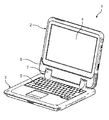
- FIG. 1 is a schematic view showing the appearance of the electronic device 1 of the present disclosure.
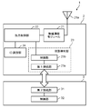
- FIG. 2 is a block diagram showing an internal configuration of the electronic device 1 of FIG.
- FIG. 3 is a schematic view showing a tablet state of the electronic device 1 of FIG.
- FIG. 4 is a schematic view showing a laptop state of the electronic device 1 of FIG.
- the electronic device 1 includes a tablet 2 having a display unit 4 and a main body unit 3 having a keyboard 5.
- the tablet 2 and the main body 3 are detachably connected to each other.
- the tablet 2 corresponds to the "first device” of the present disclosure
- the main body 3 corresponds to the "second device” of the present disclosure.
- the tablet 2 has a wireless communication module 21, an output control unit 22, a state detection unit 23, and an ID identification unit 24.
- the main body unit 3 has a second connection unit 31 and a control unit 32.
- the electronic device 1 can also be used as a single tablet 2 corresponding to the "first device" of the present disclosure.
- the electronic device 1 can be used like a laptop PC including a keyboard 5 and a display unit 4 by further connecting the tablet 2 to the main body unit 3 corresponding to the "second device” of the present disclosure. (See FIG. 4). That is, the electronic device 1 can be used in the tablet state shown in FIG. 3 and the laptop state shown in FIG.
- the tablet state is a state in which the tablet 2 and the main body 3 are not connected and are separated, and the tablet 2 is used alone. Input / output to the electronic device 1 is performed by the touch panel or the like of the display unit 4.
- the tablet state corresponds to the "first state" of the present disclosure.
- the laptop state is a state in which the tablet 2 and the main body 3 are connected, and the tablet 2 and the main body 3 are open. In the laptop state, the tablet 2 and the main body 3 are connected by inserting the tablet 2 into the socket 6 of the main body 3. In the laptop state, the keyboard 5 can be used to input and output to and from the electronic device 1.
- the keyboard 5 is an example of an input unit.
- the laptop state corresponds to the "second state" of the present disclosure.
- the tablet 2 is inserted into the socket 6 of the main body 3, the tablet 2 and the main body 3 are arranged so as to face each other, and neither the display 4 of the tablet 2 nor the keyboard 5 of the main body 3 is exposed. Is called the stored state.
- the usage state of the electronic device 1 is the tablet state
- input / output is performed using the touch panel or the like of the display unit 4, so that the distance between the electronic device 1 and the human body may become short. Therefore, when the usage state of the electronic device 1 is the tablet state (first state), it is preferable to reduce the output of the wireless communication module 21 in consideration of the SAR regulation.
- the SAR regulation is applied without reducing the output of the wireless communication module 21. Can be met. Further, since the SAR regulation is defined in the state where the electronic device is used, it is not necessary to control the output of the wireless communication module 21 in the stored state.
- the wireless communication module 21 transmits and receives radio waves to and from an external device.
- the electronic device 1 can be connected to the Internet or the like by a function such as a wireless LAN or a wireless WAN.
- the wireless communication module 21 is connected to the antenna 21a and transmits / receives radio waves through the antenna 21a.
- one wireless communication module 21 is connected to one antenna 21a, but the number of antennas and wireless communication modules is not limited to this.
- the output control unit 22 controls the output of the wireless communication module 21. For example, in a country where the regulation value of SAR is low, such as the United States or Canada, the output of the wireless communication module can be reduced to control the SAR to be less than or equal to a predetermined value.
- the output control unit 22 outputs the output of the wireless communication module 21 based on the usage state of the electronic device 1 detected by the state detection unit 23 and the ID information (country ID) identified by the ID identification unit, which will be described later. Control.
- the output control unit 22 can be composed of, for example, a CPU, an MPU, a DSP, an FPGA, an ASIC, or the like.
- the function of the output control unit 22 may be configured only by hardware, or may be realized by combining hardware and software.
- the output control unit 22 realizes a predetermined function by reading data or a program stored in a storage area (not shown) in the output control unit 22 and performing various arithmetic processes.
- FIG. 5 is a table showing the output limit of the wireless communication module of the electronic device 1 of FIG.
- the output control unit 22 controls the output of the wireless communication module depending on the country in which the electronic device 1 is located.
- the countries described as "low output A” and “low output B" in the output restriction column control the output of the wireless communication module 21 to low output.
- the low output A and the low output B indicate that the output magnitude of the wireless communication module 21 differs depending on the regulation value of SAR, but even if the output magnitude is the same between the low output A and the low output B. I do not care.
- the country or region described as "standard output” in the output restriction column uses the output of the wireless communication module 21 as the standard output.
- the standard output means that the output of the wireless communication module 21 is not particularly controlled.
- the output limit value of each country or region in FIG. 5 may be changed due to a change in laws and regulations.
- FIG. 5 for example, when the regulation value of SAR in Japan is changed to control the output of the wireless communication module 21 to a low output, the output limit in Japan in the table of FIG. 5 is changed from "standard output” to "low output A". Alternatively, it can be changed to "low output B".
- the state detection unit 23 detects the usage state of the electronic device 1.
- the state detection unit 23 includes a first connection unit 23a and a control unit 23b.
- the first connection portion 23a is, for example, a connection terminal arranged on the tablet 2.
- a second connection portion 31 is arranged in the main body portion 3, and the tablet 2 and the main body portion 3 are electrically connected by connecting the first connection portion 23a and the second connection portion 31.
- the control unit 23b determines the usage state of the electronic device 1 based on the presence or absence of a connection between the first connection unit 23a and the second connection unit 31.
- the control unit 23b can be composed of, for example, a CPU, an MPU, a DSP, an FPGA, an ASIC, or the like.
- the function of the control unit 23b may be configured only by hardware, or may be realized by combining hardware and software.
- the control unit 23b realizes a predetermined function by reading data or a program stored in a storage area (not shown) in the control unit 23b and performing various arithmetic processes.
- the control unit 32 of the main body 3 transmits, for example, the input contents from the keyboard 5 of the main body 3 to the control unit 23b of the tablet 2 when the first connection unit 23a and the second connection unit 31 are connected. Has a role.
- the control unit 32 of the main body 3 has the same configuration as the control unit 23b of the tablet 2.
- the control unit 23b of the state detection unit 23 detects the usage state of the electronic device 1 based on the presence or absence of an electrical connection between the first connection unit 23a and the second connection unit 31. For example, the state detection unit 23 detects that the electronic device 1 is in the first state when the first connection unit 23a and the second connection unit 31 are not connected. The state detection unit 23 detects that it is in the second state when the first connection unit 23a and the second connection unit 31 are connected.
- the ID identification unit 24 identifies the ID information.
- the ID identification unit 24 identifies the country ID indicating the country or region where the electronic device 1 is located. That is, in the present embodiment, the country ID corresponds to the "ID information" of the present disclosure.
- the country ID can be stored in, for example, a storage device (not shown) included in the electronic device 1. Further, the initial value of the country ID can be set in advance according to, for example, the destination of the electronic device 1.
- the ID identification unit 24 can identify the country ID set in the electronic device 1 and identify the country or region in which the electronic device 1 is located.
- the output control unit 22 controls the output of the wireless communication module 21 based on the country or region information identified by the ID identification unit 24.
- FIG. 6 is a flowchart showing output control of the wireless communication module in the electronic device 1 of FIG.
- the ID identification unit 24 identifies the country ID set in the electronic device 1 (step S100). Based on the country ID identified by the ID identification unit 24, the output control unit 22 determines whether or not the output control unit 22 is an output restricted country (step S101). The determination of whether or not the country is an output-restricted country is performed based on the table shown in the table of FIG.
- the table of FIG. 5 can be stored in, for example, a storage area in the output control unit 22.
- step S101 when the country identified by the ID identification unit 24 is North America or South Korea, there is an output restriction, so the result is Yes in step S101.
- the result when the country identified by the ID identification unit 24 is other than North America or South Korea, the result is No in step S101 because there is no output restriction. If there is no output limit, the process proceeds to step S108, and the output control unit 22 sets the output of the wireless communication module 21 as the standard output.
- the state detection unit 23 detects the usage state of the electronic device 1 (step S102).
- the output control unit 22 determines whether or not the usage state detected by the state detection unit 23 is a tablet state (step S103). When it is determined that the tablet is not in the tablet state (No in step S103), the output control unit 22 sets the output of the wireless communication module 21 as the standard output (step S107). When it is determined that the tablet is in the tablet state (Yes in step S103), the output control unit 22 sets the output of the wireless communication module 21 to a low output (step S104).
- the low output of the wireless communication module 21 means that the output of the wireless communication module 21 is reduced by the output control unit 22.
- the output control unit 22 lowers the output of the wireless communication module 21 as compared with the case when the laptop state (second state) is detected.
- the output control unit 22 so as to satisfy the SAR regulation value of 1.6 W / kg (1 g average) in North America.
- the output of the wireless communication module 21 is reduced from the standard output.
- the output magnitude of the wireless communication module 21 may be set to a different value according to the SAR regulation value of each country as well as two types of standard output and low output.
- the state detection unit 23 determines whether or not the usage state of the electronic device 1 has been changed (step S105).
- the process returns to step S103.
- the output control unit 22 fixes the output of the wireless communication module 21 (step S106).
- the power of the electronic device 1 is turned off, the process ends.
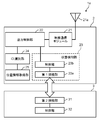
- FIG. 7 is a block diagram showing an electronic device 1a according to a modified example of the first embodiment.
- the electronic device 1a may have a position information acquisition unit 25 for acquiring position information.
- the position information acquisition unit 25 can, for example, receive a GPS signal to identify the country or region where the electronic device 1 is located.
- the location information of the wireless access point may be acquired, and the country or region where the electronic device 1 is located may be identified based on this location information.
- the country ID is updated based on the position information acquired by the position information acquisition unit 25.
- the ID identification unit 24 can identify the country or region where the electronic device 1a is located by the updated country ID.
- the country ID is automatically updated when the electronic device 1a is used in a country or region other than the country or region indicated by the preset country ID. Therefore, for example, when moving from a country or region having "standard output” in the table of FIG. 5 to a country or region having "low output A” or “low output B", or vice versa, the country is manually moved. It is not necessary to update the ID. Therefore, even when the electronic device 1a is used across countries or regions having different output restrictions, the output control unit 22 can appropriately control the output of the wireless communication module based on the country ID and the usage status. ..
- the output of the wireless communication module 21 can be controlled based on the usage state. For example, in the case of a tablet state in which the distance between the electronic device 1 and the human body may be short, the output of the wireless communication module 21 can be reduced.
- the output of the wireless communication module 21 is controlled based on the usage state, it is not necessary to use parts such as a proximity sensor. By controlling the output of the wireless communication module 21 without using a proximity sensor or the like, it is possible to provide an electronic device that satisfies the SAR regulation without using expensive parts.
- the information identified by the ID identification unit 24 is not limited to the country ID, and may be an identification ID for controlling the output of the wireless communication module 21.
- the electronic device 1 having a structure in which the tablet 2 and the main body 3 can be attached and detached has been described, but the electronic device is not limited to the detachable configuration.
- the configuration in which one antenna 21a is connected to the wireless communication module 21 has been described, but a plurality of antennas may be connected to the wireless communication module 21. Further, the antenna 21a of the wireless communication module 21 may be capable of receiving GPS signals.
- the output control unit 22 has described a configuration in which the output of the wireless communication module 21 is controlled to a standard output or a low output.
- the output value may be changed according to the regulation value for each.
- the state detection unit 23 determines the usage state of the electronic device 1 based on the presence or absence of an electrical connection between the first connection unit 23a and the second connection unit 31 has been described.
- the configuration of the state detection unit 23 is not limited to this.
- the state detection unit 23 may determine whether or not there is a physical connection between the first connection unit 23a and the second connection unit 31 by, for example, a switch or the like.
- the configuration in which the electronic devices 1 and 1a are connected to the tablet 2 and the main body 3 is described.
- the electronic devices 1 and 1a are used in the car mounter state and the cradle state. be able to.
- the car mounter state is a state in which the tablet 2 is connected to a car mounter which is a peripheral device for mounting on an automobile.
- the cradle state is a state in which the tablet 2 is connected to a cradle which is a peripheral device for charging or using as a stand.
- the car mounter and cradle correspond to the "second device" of the present disclosure
- the car mounter state and cradle state correspond to the "second state" of the present disclosure.
- FIG. 8 is a schematic view showing the appearance of the electronic device 1b according to the second embodiment.
- FIG. 9 is a schematic view showing a convertible state of the electronic device 1b of FIG.
- FIG. 10 is a block diagram showing an internal configuration of the electronic device 1b of FIG.
- the electronic device 1b is rotatably connected to the first housing 20, the first housing 20, and the hinge 7. It is different from the first embodiment in that it has a body 30, the state detection unit 28 of the first housing 20 has a magnetic sensor 23c, and the second housing 30 has a magnet 33.
- the state detection unit 28 includes a magnetic sensor 23c that detects the opening angle between the first housing 20 and the second housing 30.
- the state detection unit 28 has a magnetic sensor 23c electrically connected to the control unit 23b.
- a magnet 33 is arranged in the second housing 30.
- the magnetic sensor 23c and the magnet 33 can detect the opening angle between the first housing 20 and the second housing 30.
- the control unit 23b sets the first housing 20 and the second housing 30 based on the direction of the magnetic flux detected by the magnetic sensor 23c.
- the opening angle of is determined.
- the opening angle is an angle formed by the first housing 20 and the second housing 30 rotatably connected via the hinge 7.
- the state detection unit 23 determines that the usage state of the electronic device 1b is the laptop state. Further, in the present embodiment, the first housing 20 can be rotated in the direction of the arrow (the direction in which the display unit 4 and the keyboard 5 are separated from each other) from the state shown in FIG. When the first housing 20 is rotated, as shown in FIG. 9, the first housing 20 and the second housing 30 are arranged so as to face each other.
- the state detection unit 23 is in a convertible state of the usage state of the electronic device 1b. Is determined. In the convertible state, the opening angle between the first housing 20 and the second housing 30 is 360 degrees. In the convertible state, the display unit 4 and the keyboard 5 which is an input unit are exposed, respectively, and the back surface of the first housing 20 on the opposite side of the display unit 4 and the back surface of the second housing 30 on the opposite side of the keyboard 5. Are overlapping.
- the convertible state In the convertible state, input / output to the electronic device 1b is performed by the touch panel of the display unit 4 or the like, as in the tablet state of the first embodiment. Therefore, when the usage state of the electronic device 1b is the convertible state (third state), it is preferable to reduce the output of the wireless communication module 21 in consideration of the SAR regulation. On the other hand, in the laptop state (fourth state), since it is assumed that the electronic device 1 is used at a certain distance from the human body, the SAR regulation is applied without reducing the output of the wireless communication module 21. Can be met. In this embodiment, the convertible state corresponds to the "third state" of the present disclosure, and the laptop state corresponds to the "fourth state” of the present disclosure.
- FIG. 11 is a flowchart showing output control of the wireless communication module 21 in the electronic device 1b of FIG. The operation of the output control of the wireless communication module 21 in the present embodiment will be described with reference to FIG.
- steps S200 to S202 and steps S204 to S208 in FIG. 11 are the same as steps S100 to S102 and steps S104 to S108 of the first embodiment, the description thereof will be omitted.
- step S203 the state detection unit 23 determines whether or not the usage state of the electronic device 1b is a convertible state. When it is determined that the convertible state is not obtained (No in step S203), the output control unit 22 sets the output of the wireless communication module 21 as the standard output (step S207). When it is determined that the convertible state is present (Yes in step S203), the output control unit 22 sets the output of the wireless communication module 21 to a low output (step S204).
- the low output of the wireless communication module 21 means that the output of the wireless communication module 21 is reduced by the output control unit 22.
- the output control unit 22 lowers the output of the wireless communication module 21 when the convertible state (third state) is detected by the state detection unit 23 than when the laptop state (fourth state) is detected.
- FIG. 12 is a schematic view showing an electronic device 1c according to a modified example of the second embodiment.
- the first housing 20 is temporarily removed from the second housing 30, and the first housing 20 is rotated 180 degrees around the axis Z shown in FIG. 2 Connect to the housing 30.
- the electronic device 1c is in a convertible state (third state) by closing the first housing 20 and the second housing 30 so that the first housing 20 covers the keyboard 5 side of the second housing 30. ).
- the opening angle between the first housing 20 and the second housing 30 is 0 degrees.
- the display unit 4 is exposed, but the keyboard 5 is covered with the first housing 20 and is not exposed.
- the configuration in which the magnetic sensor 23c is arranged in the first housing 20 and the magnet 33 is arranged in the second housing 30 has been described, but the magnet is arranged in the first housing 20.
- a magnetic sensor may be arranged in the second housing 30. Further, a plurality of magnetic sensors 23c and magnets 33 may be arranged respectively.
- the opening angle between the first housing 20 and the second housing 30 is detected by the magnetic sensor 23c and the magnet 33, but the angle sensor, the gyro sensor, the acceleration sensor, or the like is used in the first housing. Anything that detects the opening angle between the body 20 and the second housing 30 may be used.
- first embodiment and the second embodiment may be combined or may be used alone.
- FIG. 13 is a block diagram showing an internal configuration of the electronic device 1d according to the third embodiment of the present disclosure.
- FIG. 14 is a diagram showing an arrangement of antennas of the electronic device 1d of FIG.
- FIG. 15 is a table showing the outputs of the wireless communication modules 26 and 27 for each country identified by the ID identification unit 24 of the electronic device 1d of FIG.
- the third embodiment is different from the first embodiment in that the electronic device 1d has two wireless communication modules 26 and 27, as shown in FIG.
- the wireless communication module 26 is connected to the two antennas 26a and 26b
- the wireless communication module 27 is connected to the two antennas 27a and 27b.
- Each of the antennas 26a to 27b is arranged on the tablet 2 as shown in FIG.
- the arrangement of the antennas 26a to 27b in FIG. 14 is an example, and the arrangement positions of the antennas 26a to 27b are not limited to this.
- the wireless communication module 26 is a module for a wireless LAN
- the wireless communication module 27 is a module for a wireless WAN.
- the outputs of the wireless communication module 26 and the wireless communication module 27 are controlled for each country ID identified by the ID identification unit 24.
- the wireless communication module 26 (wireless LAN) and the wireless communication module 27 (wireless WAN) can have different output controls.
- the output control unit 22 refers to the wireless communication module 27 based on the usage status of the electronic device 1d. Control to reduce the output. On the other hand, the output control unit 22 does not reduce the output of the wireless communication module 26.
- the output control unit 22 may exceed the SAR regulation for each country among the two wireless communication modules 26 and 27 based on the country identified by the ID identification unit 24. Can reduce the output. Even when the electronic device 1d has a plurality of wireless communication modules, it is possible to perform output control without using parts such as sensors.
- the number of wireless communication modules may be one or more.
- FIG. 16 is a table showing the output of the wireless communication module according to the opening angle between the first housing 20 and the second housing 30 of the electronic device 1 of FIG.
- the fourth embodiment is different from the second embodiment in that the output of the wireless communication module 21 is controlled based on the opening angle between the first housing 20 and the second housing 30.
- the opening angle refers to the first housing 20 and the second housing when the electronic device 1c of FIG. 12 described in the modified example of the second embodiment is in a convertible state (a state in which the display unit 4 is exposed and the keyboard 5 is not exposed). This is the angle formed by the first housing 20 and the second housing 30 with the angle formed by the body 30 being 0 degrees.
- the output at the low output 1 is the smallest, and the output of the wireless communication module 21 increases in the order of the low output 2, the low output 3, the low output 4, and the standard output.
- the output of the wireless communication module 21 is controlled to be the lowest by the output control unit 22.
- the opening angle is 0 to 180 degrees
- the output of the wireless communication module 21 is controlled to be gradually increased according to the opening angle.
- the opening angle exceeds 180 degrees, the wireless communication module 21 is controlled to the standard output.
- the opening angle between the first housing 20 and the second housing 30 is formed. Is 360 degrees, so the wireless communication module 21 is controlled to the standard output when the opening angle is 0 to 180 degrees, and the output of the wireless communication module 21 decreases as the opening angle increases from 180 degrees to 360 degrees. It may be controlled so as to be.
- the opening angle is detected by the state detection unit 28 using the magnetic sensor 23c or the like shown in FIG. 10 described above.
- the output of the wireless communication module 21 can be controlled more flexibly.
- This disclosure can be widely applied to electronic devices equipped with a wireless communication module.
Landscapes
- Engineering & Computer Science (AREA)
- Theoretical Computer Science (AREA)
- Computer Hardware Design (AREA)
- Human Computer Interaction (AREA)
- Physics & Mathematics (AREA)
- General Engineering & Computer Science (AREA)
- General Physics & Mathematics (AREA)
- Computer Networks & Wireless Communication (AREA)
- Signal Processing (AREA)
- Transceivers (AREA)
- Telephone Function (AREA)
Priority Applications (3)
| Application Number | Priority Date | Filing Date | Title |
|---|---|---|---|
| CN202180019782.1A CN115280746A (zh) | 2020-03-23 | 2021-02-16 | 电子设备 |
| JP2022509401A JP7422284B2 (ja) | 2020-03-23 | 2021-02-16 | 電子機器 |
| US17/940,331 US12314087B2 (en) | 2020-03-23 | 2022-09-08 | Electronic device |
Applications Claiming Priority (2)
| Application Number | Priority Date | Filing Date | Title |
|---|---|---|---|
| JP2020-051159 | 2020-03-23 | ||
| JP2020051159 | 2020-03-23 |
Related Child Applications (1)
| Application Number | Title | Priority Date | Filing Date |
|---|---|---|---|
| US17/940,331 Continuation US12314087B2 (en) | 2020-03-23 | 2022-09-08 | Electronic device |
Publications (1)
| Publication Number | Publication Date |
|---|---|
| WO2021192729A1 true WO2021192729A1 (ja) | 2021-09-30 |
Family
ID=77892456
Family Applications (1)
| Application Number | Title | Priority Date | Filing Date |
|---|---|---|---|
| PCT/JP2021/005596 Ceased WO2021192729A1 (ja) | 2020-03-23 | 2021-02-16 | 電子機器 |
Country Status (4)
| Country | Link |
|---|---|
| US (1) | US12314087B2 (https=) |
| JP (1) | JP7422284B2 (https=) |
| CN (1) | CN115280746A (https=) |
| WO (1) | WO2021192729A1 (https=) |
Cited By (1)
| Publication number | Priority date | Publication date | Assignee | Title |
|---|---|---|---|---|
| US12418612B2 (en) | 2021-10-22 | 2025-09-16 | Samsung Electronics Co., Ltd. | Electronic device for changing operation of wireless communication based on change of angle of housing and method therefor |
Families Citing this family (2)
| Publication number | Priority date | Publication date | Assignee | Title |
|---|---|---|---|---|
| JP1721020S (ja) * | 2021-06-01 | 2022-07-29 | 携帯用電子計算機接続端子付きキーボード | |
| USD1020761S1 (en) * | 2022-06-28 | 2024-04-02 | Getac Technology Corporation | Keyboard dock |
Citations (7)
| Publication number | Priority date | Publication date | Assignee | Title |
|---|---|---|---|---|
| JP2009232437A (ja) * | 2008-02-28 | 2009-10-08 | Kyocera Corp | 無線通信端末及び無線通信方法 |
| JP2012235184A (ja) * | 2011-04-28 | 2012-11-29 | Fujitsu Ltd | 情報処理装置、電波強度制御方法およびプログラム |
| JP2013255156A (ja) * | 2012-06-08 | 2013-12-19 | Lenovo Singapore Pte Ltd | 無線端末装置のアンテナ出力を制御する方法、コンピュータ・プログラムおよび無線端末装置 |
| JP2016048413A (ja) * | 2014-08-27 | 2016-04-07 | 株式会社東芝 | システム、仮想デスクトップ環境選択方法および情報処理装置 |
| US20160149597A1 (en) * | 2014-11-26 | 2016-05-26 | Kabushiki Kaisha Toshiba | Electronic apparatus |
| JP2017126887A (ja) * | 2016-01-14 | 2017-07-20 | パナソニックIpマネジメント株式会社 | 携帯通信端末装置 |
| JP2018061155A (ja) * | 2016-10-06 | 2018-04-12 | レノボ・シンガポール・プライベート・リミテッド | 情報処理装置、情報処理装置の制御方法、及び情報処理装置の制御プログラム |
Family Cites Families (6)
| Publication number | Priority date | Publication date | Assignee | Title |
|---|---|---|---|---|
| US5974238A (en) * | 1996-08-07 | 1999-10-26 | Compaq Computer Corporation | Automatic data synchronization between a handheld and a host computer using pseudo cache including tags and logical data elements |
| JP4566825B2 (ja) | 2005-06-03 | 2010-10-20 | レノボ・シンガポール・プライベート・リミテッド | 携帯端末装置のアンテナの制御方法及び当該携帯端末装置 |
| JP4541979B2 (ja) * | 2005-06-21 | 2010-09-08 | 株式会社日立国際電気 | 無線通信システム |
| JP2015046840A (ja) * | 2013-08-29 | 2015-03-12 | シャープ株式会社 | 通信装置、エネルギー制御方法、及びエネルギー制御プログラム |
| JP5894138B2 (ja) * | 2013-12-09 | 2016-03-23 | レノボ・シンガポール・プライベート・リミテッド | 携帯型情報処理装置、そのアンテナ制御方法、及びコンピュータが実行可能なプログラム |
| CN110875963A (zh) * | 2018-08-29 | 2020-03-10 | Oppo广东移动通信有限公司 | 电子设备 |
-
2021
- 2021-02-16 CN CN202180019782.1A patent/CN115280746A/zh active Pending
- 2021-02-16 JP JP2022509401A patent/JP7422284B2/ja active Active
- 2021-02-16 WO PCT/JP2021/005596 patent/WO2021192729A1/ja not_active Ceased
-
2022
- 2022-09-08 US US17/940,331 patent/US12314087B2/en active Active
Patent Citations (7)
| Publication number | Priority date | Publication date | Assignee | Title |
|---|---|---|---|---|
| JP2009232437A (ja) * | 2008-02-28 | 2009-10-08 | Kyocera Corp | 無線通信端末及び無線通信方法 |
| JP2012235184A (ja) * | 2011-04-28 | 2012-11-29 | Fujitsu Ltd | 情報処理装置、電波強度制御方法およびプログラム |
| JP2013255156A (ja) * | 2012-06-08 | 2013-12-19 | Lenovo Singapore Pte Ltd | 無線端末装置のアンテナ出力を制御する方法、コンピュータ・プログラムおよび無線端末装置 |
| JP2016048413A (ja) * | 2014-08-27 | 2016-04-07 | 株式会社東芝 | システム、仮想デスクトップ環境選択方法および情報処理装置 |
| US20160149597A1 (en) * | 2014-11-26 | 2016-05-26 | Kabushiki Kaisha Toshiba | Electronic apparatus |
| JP2017126887A (ja) * | 2016-01-14 | 2017-07-20 | パナソニックIpマネジメント株式会社 | 携帯通信端末装置 |
| JP2018061155A (ja) * | 2016-10-06 | 2018-04-12 | レノボ・シンガポール・プライベート・リミテッド | 情報処理装置、情報処理装置の制御方法、及び情報処理装置の制御プログラム |
Cited By (1)
| Publication number | Priority date | Publication date | Assignee | Title |
|---|---|---|---|---|
| US12418612B2 (en) | 2021-10-22 | 2025-09-16 | Samsung Electronics Co., Ltd. | Electronic device for changing operation of wireless communication based on change of angle of housing and method therefor |
Also Published As
| Publication number | Publication date |
|---|---|
| US12314087B2 (en) | 2025-05-27 |
| JP7422284B2 (ja) | 2024-01-26 |
| CN115280746A (zh) | 2022-11-01 |
| US20230004195A1 (en) | 2023-01-05 |
| JPWO2021192729A1 (https=) | 2021-09-30 |
Similar Documents
| Publication | Publication Date | Title |
|---|---|---|
| US12314087B2 (en) | Electronic device | |
| EP4270797B1 (en) | Antenna and foldable electronic device including the same | |
| US11281254B2 (en) | Foldable electronic device including electronic pen | |
| CN105122174B (zh) | 控制功率的方法及其电子设备 | |
| KR102545668B1 (ko) | 안테나 및 이를 포함하는 전자 장치 | |
| US8384541B2 (en) | Charging method for a mobile terminal | |
| EP3729794B1 (en) | Electronic device including conductive member electrically coupled to opening of bracket for adjusting resonance generated from the opening | |
| US20070037619A1 (en) | Method for controlling antennas of mobile terminal device and such a mobile terminal device | |
| KR20100125935A (ko) | 이동 단말기 및 이를 이용한 콜 기능 수행 방법 | |
| US20210311524A1 (en) | Electronic device with magnetic field sensor design for detection of multiple accessories | |
| US8879722B1 (en) | Wireless communication earpiece | |
| KR20200044394A (ko) | 거치 부재를 포함하는 전자 장치 | |
| KR102769071B1 (ko) | 안테나를 포함하는 전자 장치 | |
| KR102866896B1 (ko) | 전자 장치 및 전력 제어 방법 | |
| EP1988690B1 (en) | Acoustic device | |
| JP2003166826A (ja) | 折り畳み式携帯端末の開閉検知スイッチ | |
| US7319890B2 (en) | Detection method and foldable electronic device thereof | |
| KR20190088192A (ko) | 안테나의 위상을 스윕하기 위한 전자 장치 | |
| KR102408872B1 (ko) | 공진 주파수를 조정하는 회로 및 이를 포함하는 전자 장치 | |
| EP3977561B1 (en) | Antenna and electronic device including the same | |
| KR102756064B1 (ko) | 안테나 및 그립 센서를 포함하는 전자 장치 | |
| EP4579434A1 (en) | Electronic device, and method for reducing reset time of audio signal processing thereof | |
| US20120081254A1 (en) | Antenna device for portable terminal | |
| US20250365532A1 (en) | Electronic device comprising speaker module | |
| KR20200133841A (ko) | 사용자의 위치를 감지하기 위한 전자 장치 |
Legal Events
| Date | Code | Title | Description |
|---|---|---|---|
| 121 | Ep: the epo has been informed by wipo that ep was designated in this application |
Ref document number: 21776043 Country of ref document: EP Kind code of ref document: A1 |
|
| ENP | Entry into the national phase |
Ref document number: 2022509401 Country of ref document: JP Kind code of ref document: A |
|
| NENP | Non-entry into the national phase |
Ref country code: DE |
|
| 122 | Ep: pct application non-entry in european phase |
Ref document number: 21776043 Country of ref document: EP Kind code of ref document: A1 |