WO2021192729A1 - Electronic device - Google Patents
Electronic device Download PDFInfo
- Publication number
- WO2021192729A1 WO2021192729A1 PCT/JP2021/005596 JP2021005596W WO2021192729A1 WO 2021192729 A1 WO2021192729 A1 WO 2021192729A1 JP 2021005596 W JP2021005596 W JP 2021005596W WO 2021192729 A1 WO2021192729 A1 WO 2021192729A1
- Authority
- WO
- WIPO (PCT)
- Prior art keywords
- electronic device
- state
- output
- wireless communication
- housing
- Prior art date
Links
Images


Classifications
-
- G—PHYSICS
- G06—COMPUTING; CALCULATING OR COUNTING
- G06F—ELECTRIC DIGITAL DATA PROCESSING
- G06F1/00—Details not covered by groups G06F3/00 - G06F13/00 and G06F21/00
- G06F1/16—Constructional details or arrangements
- G06F1/1613—Constructional details or arrangements for portable computers
- G06F1/1633—Constructional details or arrangements of portable computers not specific to the type of enclosures covered by groups G06F1/1615 - G06F1/1626
- G06F1/1675—Miscellaneous details related to the relative movement between the different enclosures or enclosure parts
- G06F1/1677—Miscellaneous details related to the relative movement between the different enclosures or enclosure parts for detecting open or closed state or particular intermediate positions assumed by movable parts of the enclosure, e.g. detection of display lid position with respect to main body in a laptop, detection of opening of the cover of battery compartment
-
- G—PHYSICS
- G06—COMPUTING; CALCULATING OR COUNTING
- G06F—ELECTRIC DIGITAL DATA PROCESSING
- G06F1/00—Details not covered by groups G06F3/00 - G06F13/00 and G06F21/00
- G06F1/16—Constructional details or arrangements
- G06F1/1613—Constructional details or arrangements for portable computers
- G06F1/1632—External expansion units, e.g. docking stations
-
- G—PHYSICS
- G06—COMPUTING; CALCULATING OR COUNTING
- G06F—ELECTRIC DIGITAL DATA PROCESSING
- G06F1/00—Details not covered by groups G06F3/00 - G06F13/00 and G06F21/00
- G06F1/16—Constructional details or arrangements
- G06F1/1613—Constructional details or arrangements for portable computers
- G06F1/1633—Constructional details or arrangements of portable computers not specific to the type of enclosures covered by groups G06F1/1615 - G06F1/1626
- G06F1/1637—Details related to the display arrangement, including those related to the mounting of the display in the housing
- G06F1/1654—Details related to the display arrangement, including those related to the mounting of the display in the housing the display being detachable, e.g. for remote use
-
- G—PHYSICS
- G06—COMPUTING; CALCULATING OR COUNTING
- G06F—ELECTRIC DIGITAL DATA PROCESSING
- G06F1/00—Details not covered by groups G06F3/00 - G06F13/00 and G06F21/00
- G06F1/16—Constructional details or arrangements
- G06F1/1613—Constructional details or arrangements for portable computers
- G06F1/1633—Constructional details or arrangements of portable computers not specific to the type of enclosures covered by groups G06F1/1615 - G06F1/1626
- G06F1/1675—Miscellaneous details related to the relative movement between the different enclosures or enclosure parts
- G06F1/1683—Miscellaneous details related to the relative movement between the different enclosures or enclosure parts for the transmission of signal or power between the different housings, e.g. details of wired or wireless communication, passage of cabling
-
- H—ELECTRICITY
- H04—ELECTRIC COMMUNICATION TECHNIQUE
- H04M—TELEPHONIC COMMUNICATION
- H04M1/00—Substation equipment, e.g. for use by subscribers
Definitions
- This disclosure relates to electronic devices.
- SAR Specific Absorption Rate
- Patent Document 1 discloses an electronic device having a proximity sensor and reducing the output of a wireless communication module when approaching a human body.
- the electronic device of Patent Document 1 still has room for improvement in that the output of the wireless communication module is efficiently controlled.
- an object of the present disclosure is to provide an electronic device capable of efficiently controlling the output of the wireless communication module.
- One or more wireless communication modules that send and receive radio waves to and from external devices, An output control unit that controls the output of the one or more wireless communication modules, and A state detector that detects the usage status of electronic devices, An ID identification unit that identifies ID information and With The output control unit controls the output of the one or more wireless communication modules based on the usage state detected by the state detection unit and the ID information identified by the ID identification unit. do.
- FIG. It is the schematic which shows the appearance of the electronic device which concerns on Embodiment 1.
- FIG. It is a block diagram which shows the internal structure of the electronic device of FIG. It is the schematic which shows the tablet state of the electronic device of FIG. It is the schematic which shows the laptop state of the electronic device of FIG. It is a table which shows the output of the wireless communication module of the electronic device of FIG. It is a flowchart which shows the output control of the wireless communication module in the electronic device of FIG. It is a block diagram which shows the modification of the internal structure of the electronic device of FIG. It is the schematic which shows the appearance of the electronic device which concerns on Embodiment 2.
- FIG. It is the schematic which shows the convertible state of the electronic device of FIG.
- the allowable specific absorption rate (SAR) of the electromagnetic wave radiated by the antenna 21a is set for each country.
- SAR refers to the amount of electromagnetic wave energy absorbed by a unit mass of the human body per unit time.
- the SAR for local exposure of the human body is regulated to 1.6 W / kg or less per 1 g of living tissue. Further, in Europe, Oceania countries, Japan, etc., it is stipulated that the average of 10 g of living tissue should be 2.0 W / kg or less.
- an electronic device such as a tablet PC that inputs / outputs using a touch panel or the like tends to be closer to the human body when used than an electronic device such as a laptop PC that inputs / outputs using a keyboard or the like. It is in. Therefore, especially in tablet PCs, it is required to reduce the output of the wireless communication module in order to satisfy the SAR regulation.
- the electronic device described in Patent Document 1 has a configuration that satisfies the SAR regulation by using a proximity sensor to reduce the output of the wireless communication module when the human body and the electronic device are closer than a predetermined distance. be.
- a method of arranging a plurality of antennas in an electronic device and determining an antenna to be discontinued according to the usage status of the electronic device such as a display direction, a holding direction, or an installation status is being studied.
- the usage status of the electronic device such as a display direction, a holding direction, or an installation status
- a plurality of antennas are mounted on the electronic device, there is a problem that the manufacturing cost becomes high.
- some antennas are not used depending on the usage status of the electronic device, a space for arranging a plurality of antennas is required in the electronic device, and there is a problem that miniaturization is difficult.
- the present inventor devised an electronic device having a configuration for efficiently controlling the output of the wireless communication module in order to satisfy the SAR regulation, and came up with the following invention.
- the electronic device of the present disclosure includes one or more wireless communication modules that transmit and receive radio waves to and from an external device.
- An output control unit that controls the output of the one or more wireless communication modules, and A state detector that detects the usage status of electronic devices,
- An ID identification unit that identifies ID information and To be equipped.
- the output control unit controls the output of the one or more wireless communication modules based on the usage state detected by the state detection unit and the ID information identified by the ID identification unit. do.
- the ID identification unit may identify the country or region where the electronic device is located.
- the electronic device is Location information acquisition unit, which acquires location information, With The ID identification unit may identify the country or region where the electronic device is located based on the location information.
- the electronic device is A first device having the one or more wireless communication modules, the output control unit, the state detection unit, and the ID identification unit.
- the second device connected to the first device and Including The usage state may include a first state in which the first device and the second device are not connected, and a second state in which the first device and the second device are connected.
- the output of the wireless communication module can be controlled based on whether or not the first device and the second device are connected.
- the output control unit may lower the output of the one or more wireless communication modules as compared with the case when the second state is detected. ..
- the output of the wireless communication module can be changed between the first state and the second state.
- the first device is a tablet having a display unit.
- the second device may be a main body unit having an input unit.
- the output of the wireless communication module can be reduced when the tablet is used alone.
- the first device is a tablet having a display unit.
- the second device may be a car mounter or cradle connected to the first device.
- the output of the wireless communication module can be reduced when the tablet is used alone.
- the electronic device is A first housing having the one or more wireless communication modules, the output control unit, the state detection unit, the ID identification unit, and the display unit.
- a second housing that is rotatably connected to the first housing via a hinge and has an input portion, and a second housing.
- the output of the wireless communication module can be controlled based on the usage state in the electronic device that can be used in the usage state of the third state and the fourth state.
- the state detection unit may have a magnetic sensor that detects the opening angle between the first housing and the second housing.
- the third state and the fourth state can be easily detected.
- the output control unit may control the output of the one or more wireless communication modules based on the opening angle.
- the output of the wireless communication module can be controlled more flexibly by the opening angle between the first housing and the second housing.
- the output control unit may lower the output of the one or more wireless communication modules as compared with the case when the fourth state is detected. ..
- the output of the wireless communication module can be reduced when the third state is detected.
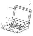
- FIG. 1 is a schematic view showing the appearance of the electronic device 1 of the present disclosure.
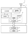
- FIG. 2 is a block diagram showing an internal configuration of the electronic device 1 of FIG.
- FIG. 3 is a schematic view showing a tablet state of the electronic device 1 of FIG.
- FIG. 4 is a schematic view showing a laptop state of the electronic device 1 of FIG.
- the electronic device 1 includes a tablet 2 having a display unit 4 and a main body unit 3 having a keyboard 5.
- the tablet 2 and the main body 3 are detachably connected to each other.
- the tablet 2 corresponds to the "first device” of the present disclosure
- the main body 3 corresponds to the "second device” of the present disclosure.
- the tablet 2 has a wireless communication module 21, an output control unit 22, a state detection unit 23, and an ID identification unit 24.
- the main body unit 3 has a second connection unit 31 and a control unit 32.
- the electronic device 1 can also be used as a single tablet 2 corresponding to the "first device" of the present disclosure.
- the electronic device 1 can be used like a laptop PC including a keyboard 5 and a display unit 4 by further connecting the tablet 2 to the main body unit 3 corresponding to the "second device” of the present disclosure. (See FIG. 4). That is, the electronic device 1 can be used in the tablet state shown in FIG. 3 and the laptop state shown in FIG.
- the tablet state is a state in which the tablet 2 and the main body 3 are not connected and are separated, and the tablet 2 is used alone. Input / output to the electronic device 1 is performed by the touch panel or the like of the display unit 4.
- the tablet state corresponds to the "first state" of the present disclosure.
- the laptop state is a state in which the tablet 2 and the main body 3 are connected, and the tablet 2 and the main body 3 are open. In the laptop state, the tablet 2 and the main body 3 are connected by inserting the tablet 2 into the socket 6 of the main body 3. In the laptop state, the keyboard 5 can be used to input and output to and from the electronic device 1.
- the keyboard 5 is an example of an input unit.
- the laptop state corresponds to the "second state" of the present disclosure.
- the tablet 2 is inserted into the socket 6 of the main body 3, the tablet 2 and the main body 3 are arranged so as to face each other, and neither the display 4 of the tablet 2 nor the keyboard 5 of the main body 3 is exposed. Is called the stored state.
- the usage state of the electronic device 1 is the tablet state
- input / output is performed using the touch panel or the like of the display unit 4, so that the distance between the electronic device 1 and the human body may become short. Therefore, when the usage state of the electronic device 1 is the tablet state (first state), it is preferable to reduce the output of the wireless communication module 21 in consideration of the SAR regulation.
- the SAR regulation is applied without reducing the output of the wireless communication module 21. Can be met. Further, since the SAR regulation is defined in the state where the electronic device is used, it is not necessary to control the output of the wireless communication module 21 in the stored state.
- the wireless communication module 21 transmits and receives radio waves to and from an external device.
- the electronic device 1 can be connected to the Internet or the like by a function such as a wireless LAN or a wireless WAN.
- the wireless communication module 21 is connected to the antenna 21a and transmits / receives radio waves through the antenna 21a.
- one wireless communication module 21 is connected to one antenna 21a, but the number of antennas and wireless communication modules is not limited to this.
- the output control unit 22 controls the output of the wireless communication module 21. For example, in a country where the regulation value of SAR is low, such as the United States or Canada, the output of the wireless communication module can be reduced to control the SAR to be less than or equal to a predetermined value.
- the output control unit 22 outputs the output of the wireless communication module 21 based on the usage state of the electronic device 1 detected by the state detection unit 23 and the ID information (country ID) identified by the ID identification unit, which will be described later. Control.
- the output control unit 22 can be composed of, for example, a CPU, an MPU, a DSP, an FPGA, an ASIC, or the like.
- the function of the output control unit 22 may be configured only by hardware, or may be realized by combining hardware and software.
- the output control unit 22 realizes a predetermined function by reading data or a program stored in a storage area (not shown) in the output control unit 22 and performing various arithmetic processes.
- FIG. 5 is a table showing the output limit of the wireless communication module of the electronic device 1 of FIG.
- the output control unit 22 controls the output of the wireless communication module depending on the country in which the electronic device 1 is located.
- the countries described as "low output A” and “low output B" in the output restriction column control the output of the wireless communication module 21 to low output.
- the low output A and the low output B indicate that the output magnitude of the wireless communication module 21 differs depending on the regulation value of SAR, but even if the output magnitude is the same between the low output A and the low output B. I do not care.
- the country or region described as "standard output” in the output restriction column uses the output of the wireless communication module 21 as the standard output.
- the standard output means that the output of the wireless communication module 21 is not particularly controlled.
- the output limit value of each country or region in FIG. 5 may be changed due to a change in laws and regulations.
- FIG. 5 for example, when the regulation value of SAR in Japan is changed to control the output of the wireless communication module 21 to a low output, the output limit in Japan in the table of FIG. 5 is changed from "standard output” to "low output A". Alternatively, it can be changed to "low output B".
- the state detection unit 23 detects the usage state of the electronic device 1.
- the state detection unit 23 includes a first connection unit 23a and a control unit 23b.
- the first connection portion 23a is, for example, a connection terminal arranged on the tablet 2.
- a second connection portion 31 is arranged in the main body portion 3, and the tablet 2 and the main body portion 3 are electrically connected by connecting the first connection portion 23a and the second connection portion 31.
- the control unit 23b determines the usage state of the electronic device 1 based on the presence or absence of a connection between the first connection unit 23a and the second connection unit 31.
- the control unit 23b can be composed of, for example, a CPU, an MPU, a DSP, an FPGA, an ASIC, or the like.
- the function of the control unit 23b may be configured only by hardware, or may be realized by combining hardware and software.
- the control unit 23b realizes a predetermined function by reading data or a program stored in a storage area (not shown) in the control unit 23b and performing various arithmetic processes.
- the control unit 32 of the main body 3 transmits, for example, the input contents from the keyboard 5 of the main body 3 to the control unit 23b of the tablet 2 when the first connection unit 23a and the second connection unit 31 are connected. Has a role.
- the control unit 32 of the main body 3 has the same configuration as the control unit 23b of the tablet 2.
- the control unit 23b of the state detection unit 23 detects the usage state of the electronic device 1 based on the presence or absence of an electrical connection between the first connection unit 23a and the second connection unit 31. For example, the state detection unit 23 detects that the electronic device 1 is in the first state when the first connection unit 23a and the second connection unit 31 are not connected. The state detection unit 23 detects that it is in the second state when the first connection unit 23a and the second connection unit 31 are connected.
- the ID identification unit 24 identifies the ID information.
- the ID identification unit 24 identifies the country ID indicating the country or region where the electronic device 1 is located. That is, in the present embodiment, the country ID corresponds to the "ID information" of the present disclosure.
- the country ID can be stored in, for example, a storage device (not shown) included in the electronic device 1. Further, the initial value of the country ID can be set in advance according to, for example, the destination of the electronic device 1.
- the ID identification unit 24 can identify the country ID set in the electronic device 1 and identify the country or region in which the electronic device 1 is located.
- the output control unit 22 controls the output of the wireless communication module 21 based on the country or region information identified by the ID identification unit 24.
- FIG. 6 is a flowchart showing output control of the wireless communication module in the electronic device 1 of FIG.
- the ID identification unit 24 identifies the country ID set in the electronic device 1 (step S100). Based on the country ID identified by the ID identification unit 24, the output control unit 22 determines whether or not the output control unit 22 is an output restricted country (step S101). The determination of whether or not the country is an output-restricted country is performed based on the table shown in the table of FIG.
- the table of FIG. 5 can be stored in, for example, a storage area in the output control unit 22.
- step S101 when the country identified by the ID identification unit 24 is North America or South Korea, there is an output restriction, so the result is Yes in step S101.
- the result when the country identified by the ID identification unit 24 is other than North America or South Korea, the result is No in step S101 because there is no output restriction. If there is no output limit, the process proceeds to step S108, and the output control unit 22 sets the output of the wireless communication module 21 as the standard output.
- the state detection unit 23 detects the usage state of the electronic device 1 (step S102).
- the output control unit 22 determines whether or not the usage state detected by the state detection unit 23 is a tablet state (step S103). When it is determined that the tablet is not in the tablet state (No in step S103), the output control unit 22 sets the output of the wireless communication module 21 as the standard output (step S107). When it is determined that the tablet is in the tablet state (Yes in step S103), the output control unit 22 sets the output of the wireless communication module 21 to a low output (step S104).
- the low output of the wireless communication module 21 means that the output of the wireless communication module 21 is reduced by the output control unit 22.
- the output control unit 22 lowers the output of the wireless communication module 21 as compared with the case when the laptop state (second state) is detected.
- the output control unit 22 so as to satisfy the SAR regulation value of 1.6 W / kg (1 g average) in North America.
- the output of the wireless communication module 21 is reduced from the standard output.
- the output magnitude of the wireless communication module 21 may be set to a different value according to the SAR regulation value of each country as well as two types of standard output and low output.
- the state detection unit 23 determines whether or not the usage state of the electronic device 1 has been changed (step S105).
- the process returns to step S103.
- the output control unit 22 fixes the output of the wireless communication module 21 (step S106).
- the power of the electronic device 1 is turned off, the process ends.
- FIG. 7 is a block diagram showing an electronic device 1a according to a modified example of the first embodiment.
- the electronic device 1a may have a position information acquisition unit 25 for acquiring position information.
- the position information acquisition unit 25 can, for example, receive a GPS signal to identify the country or region where the electronic device 1 is located.
- the location information of the wireless access point may be acquired, and the country or region where the electronic device 1 is located may be identified based on this location information.
- the country ID is updated based on the position information acquired by the position information acquisition unit 25.
- the ID identification unit 24 can identify the country or region where the electronic device 1a is located by the updated country ID.
- the country ID is automatically updated when the electronic device 1a is used in a country or region other than the country or region indicated by the preset country ID. Therefore, for example, when moving from a country or region having "standard output” in the table of FIG. 5 to a country or region having "low output A” or “low output B", or vice versa, the country is manually moved. It is not necessary to update the ID. Therefore, even when the electronic device 1a is used across countries or regions having different output restrictions, the output control unit 22 can appropriately control the output of the wireless communication module based on the country ID and the usage status. ..
- the output of the wireless communication module 21 can be controlled based on the usage state. For example, in the case of a tablet state in which the distance between the electronic device 1 and the human body may be short, the output of the wireless communication module 21 can be reduced.
- the output of the wireless communication module 21 is controlled based on the usage state, it is not necessary to use parts such as a proximity sensor. By controlling the output of the wireless communication module 21 without using a proximity sensor or the like, it is possible to provide an electronic device that satisfies the SAR regulation without using expensive parts.
- the information identified by the ID identification unit 24 is not limited to the country ID, and may be an identification ID for controlling the output of the wireless communication module 21.
- the electronic device 1 having a structure in which the tablet 2 and the main body 3 can be attached and detached has been described, but the electronic device is not limited to the detachable configuration.
- the configuration in which one antenna 21a is connected to the wireless communication module 21 has been described, but a plurality of antennas may be connected to the wireless communication module 21. Further, the antenna 21a of the wireless communication module 21 may be capable of receiving GPS signals.
- the output control unit 22 has described a configuration in which the output of the wireless communication module 21 is controlled to a standard output or a low output.
- the output value may be changed according to the regulation value for each.
- the state detection unit 23 determines the usage state of the electronic device 1 based on the presence or absence of an electrical connection between the first connection unit 23a and the second connection unit 31 has been described.
- the configuration of the state detection unit 23 is not limited to this.
- the state detection unit 23 may determine whether or not there is a physical connection between the first connection unit 23a and the second connection unit 31 by, for example, a switch or the like.
- the configuration in which the electronic devices 1 and 1a are connected to the tablet 2 and the main body 3 is described.
- the electronic devices 1 and 1a are used in the car mounter state and the cradle state. be able to.
- the car mounter state is a state in which the tablet 2 is connected to a car mounter which is a peripheral device for mounting on an automobile.
- the cradle state is a state in which the tablet 2 is connected to a cradle which is a peripheral device for charging or using as a stand.
- the car mounter and cradle correspond to the "second device" of the present disclosure
- the car mounter state and cradle state correspond to the "second state" of the present disclosure.
- FIG. 8 is a schematic view showing the appearance of the electronic device 1b according to the second embodiment.
- FIG. 9 is a schematic view showing a convertible state of the electronic device 1b of FIG.
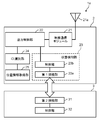
- FIG. 10 is a block diagram showing an internal configuration of the electronic device 1b of FIG.
- the electronic device 1b is rotatably connected to the first housing 20, the first housing 20, and the hinge 7. It is different from the first embodiment in that it has a body 30, the state detection unit 28 of the first housing 20 has a magnetic sensor 23c, and the second housing 30 has a magnet 33.
- the state detection unit 28 includes a magnetic sensor 23c that detects the opening angle between the first housing 20 and the second housing 30.
- the state detection unit 28 has a magnetic sensor 23c electrically connected to the control unit 23b.
- a magnet 33 is arranged in the second housing 30.
- the magnetic sensor 23c and the magnet 33 can detect the opening angle between the first housing 20 and the second housing 30.
- the control unit 23b sets the first housing 20 and the second housing 30 based on the direction of the magnetic flux detected by the magnetic sensor 23c.
- the opening angle of is determined.
- the opening angle is an angle formed by the first housing 20 and the second housing 30 rotatably connected via the hinge 7.
- the state detection unit 23 determines that the usage state of the electronic device 1b is the laptop state. Further, in the present embodiment, the first housing 20 can be rotated in the direction of the arrow (the direction in which the display unit 4 and the keyboard 5 are separated from each other) from the state shown in FIG. When the first housing 20 is rotated, as shown in FIG. 9, the first housing 20 and the second housing 30 are arranged so as to face each other.
- the state detection unit 23 is in a convertible state of the usage state of the electronic device 1b. Is determined. In the convertible state, the opening angle between the first housing 20 and the second housing 30 is 360 degrees. In the convertible state, the display unit 4 and the keyboard 5 which is an input unit are exposed, respectively, and the back surface of the first housing 20 on the opposite side of the display unit 4 and the back surface of the second housing 30 on the opposite side of the keyboard 5. Are overlapping.
- the convertible state In the convertible state, input / output to the electronic device 1b is performed by the touch panel of the display unit 4 or the like, as in the tablet state of the first embodiment. Therefore, when the usage state of the electronic device 1b is the convertible state (third state), it is preferable to reduce the output of the wireless communication module 21 in consideration of the SAR regulation. On the other hand, in the laptop state (fourth state), since it is assumed that the electronic device 1 is used at a certain distance from the human body, the SAR regulation is applied without reducing the output of the wireless communication module 21. Can be met. In this embodiment, the convertible state corresponds to the "third state" of the present disclosure, and the laptop state corresponds to the "fourth state” of the present disclosure.
- FIG. 11 is a flowchart showing output control of the wireless communication module 21 in the electronic device 1b of FIG. The operation of the output control of the wireless communication module 21 in the present embodiment will be described with reference to FIG.
- steps S200 to S202 and steps S204 to S208 in FIG. 11 are the same as steps S100 to S102 and steps S104 to S108 of the first embodiment, the description thereof will be omitted.
- step S203 the state detection unit 23 determines whether or not the usage state of the electronic device 1b is a convertible state. When it is determined that the convertible state is not obtained (No in step S203), the output control unit 22 sets the output of the wireless communication module 21 as the standard output (step S207). When it is determined that the convertible state is present (Yes in step S203), the output control unit 22 sets the output of the wireless communication module 21 to a low output (step S204).
- the low output of the wireless communication module 21 means that the output of the wireless communication module 21 is reduced by the output control unit 22.
- the output control unit 22 lowers the output of the wireless communication module 21 when the convertible state (third state) is detected by the state detection unit 23 than when the laptop state (fourth state) is detected.
- FIG. 12 is a schematic view showing an electronic device 1c according to a modified example of the second embodiment.
- the first housing 20 is temporarily removed from the second housing 30, and the first housing 20 is rotated 180 degrees around the axis Z shown in FIG. 2 Connect to the housing 30.
- the electronic device 1c is in a convertible state (third state) by closing the first housing 20 and the second housing 30 so that the first housing 20 covers the keyboard 5 side of the second housing 30. ).
- the opening angle between the first housing 20 and the second housing 30 is 0 degrees.
- the display unit 4 is exposed, but the keyboard 5 is covered with the first housing 20 and is not exposed.
- the configuration in which the magnetic sensor 23c is arranged in the first housing 20 and the magnet 33 is arranged in the second housing 30 has been described, but the magnet is arranged in the first housing 20.
- a magnetic sensor may be arranged in the second housing 30. Further, a plurality of magnetic sensors 23c and magnets 33 may be arranged respectively.
- the opening angle between the first housing 20 and the second housing 30 is detected by the magnetic sensor 23c and the magnet 33, but the angle sensor, the gyro sensor, the acceleration sensor, or the like is used in the first housing. Anything that detects the opening angle between the body 20 and the second housing 30 may be used.
- first embodiment and the second embodiment may be combined or may be used alone.
- FIG. 13 is a block diagram showing an internal configuration of the electronic device 1d according to the third embodiment of the present disclosure.
- FIG. 14 is a diagram showing an arrangement of antennas of the electronic device 1d of FIG.
- FIG. 15 is a table showing the outputs of the wireless communication modules 26 and 27 for each country identified by the ID identification unit 24 of the electronic device 1d of FIG.
- the third embodiment is different from the first embodiment in that the electronic device 1d has two wireless communication modules 26 and 27, as shown in FIG.
- the wireless communication module 26 is connected to the two antennas 26a and 26b
- the wireless communication module 27 is connected to the two antennas 27a and 27b.
- Each of the antennas 26a to 27b is arranged on the tablet 2 as shown in FIG.
- the arrangement of the antennas 26a to 27b in FIG. 14 is an example, and the arrangement positions of the antennas 26a to 27b are not limited to this.
- the wireless communication module 26 is a module for a wireless LAN
- the wireless communication module 27 is a module for a wireless WAN.
- the outputs of the wireless communication module 26 and the wireless communication module 27 are controlled for each country ID identified by the ID identification unit 24.
- the wireless communication module 26 (wireless LAN) and the wireless communication module 27 (wireless WAN) can have different output controls.
- the output control unit 22 refers to the wireless communication module 27 based on the usage status of the electronic device 1d. Control to reduce the output. On the other hand, the output control unit 22 does not reduce the output of the wireless communication module 26.
- the output control unit 22 may exceed the SAR regulation for each country among the two wireless communication modules 26 and 27 based on the country identified by the ID identification unit 24. Can reduce the output. Even when the electronic device 1d has a plurality of wireless communication modules, it is possible to perform output control without using parts such as sensors.
- the number of wireless communication modules may be one or more.
- FIG. 16 is a table showing the output of the wireless communication module according to the opening angle between the first housing 20 and the second housing 30 of the electronic device 1 of FIG.
- the fourth embodiment is different from the second embodiment in that the output of the wireless communication module 21 is controlled based on the opening angle between the first housing 20 and the second housing 30.
- the opening angle refers to the first housing 20 and the second housing when the electronic device 1c of FIG. 12 described in the modified example of the second embodiment is in a convertible state (a state in which the display unit 4 is exposed and the keyboard 5 is not exposed). This is the angle formed by the first housing 20 and the second housing 30 with the angle formed by the body 30 being 0 degrees.
- the output at the low output 1 is the smallest, and the output of the wireless communication module 21 increases in the order of the low output 2, the low output 3, the low output 4, and the standard output.
- the output of the wireless communication module 21 is controlled to be the lowest by the output control unit 22.
- the opening angle is 0 to 180 degrees
- the output of the wireless communication module 21 is controlled to be gradually increased according to the opening angle.
- the opening angle exceeds 180 degrees, the wireless communication module 21 is controlled to the standard output.
- the opening angle between the first housing 20 and the second housing 30 is formed. Is 360 degrees, so the wireless communication module 21 is controlled to the standard output when the opening angle is 0 to 180 degrees, and the output of the wireless communication module 21 decreases as the opening angle increases from 180 degrees to 360 degrees. It may be controlled so as to be.
- the opening angle is detected by the state detection unit 28 using the magnetic sensor 23c or the like shown in FIG. 10 described above.
- the output of the wireless communication module 21 can be controlled more flexibly.
- This disclosure can be widely applied to electronic devices equipped with a wireless communication module.
Abstract
An electronic device according to the present disclosure includes one or multiple wireless communication modules that transmit and receive radio waves to and from an external device, an output control unit that controls output from the one or multiple wireless communication modules, a status detection unit that detects a service status of the electronic device, and an ID identifying unit that identifies ID information. The output control unit controls output from the one or multiple wireless communication modules on the basis of the service status detected by the status detection unit and the ID information identified by the ID identifying unit.
Description
本開示は、電子機器に関する。
This disclosure relates to electronic devices.
タブレットPC、またはスマートフォン等の電子機器は、無線WANおよび無線LAN等の無線通信モジュールを搭載している。無線通信モジュールのアンテナの放射する電磁波による生体への影響が懸念されている。そこで、各国の関係機関は、人体が電磁波にさらされることによって単位質量の組織に単位時間に吸収されるエネルギー量である比吸収率(SAR:Specific Absorption Rate)を制定している。
Electronic devices such as tablet PCs or smartphones are equipped with wireless communication modules such as wireless WAN and wireless LAN. There is concern about the effects of electromagnetic waves emitted by the antenna of the wireless communication module on living organisms. Therefore, related organizations in each country have established the Specific Absorption Rate (SAR), which is the amount of energy absorbed by a tissue of unit mass in a unit time when the human body is exposed to electromagnetic waves.
例えば、特許文献1では、近接センサを有し、人体に接近した場合に無線通信モジュールの出力を低下させる電子機器が開示されている。
For example, Patent Document 1 discloses an electronic device having a proximity sensor and reducing the output of a wireless communication module when approaching a human body.
特許文献1の電子機器は、無線通信モジュールの出力を効率よく制御するという点において未だ改善の余地がある。
The electronic device of Patent Document 1 still has room for improvement in that the output of the wireless communication module is efficiently controlled.
そこで、本開示は、無線通信モジュールの出力を効率よく制御することのできる電子機器を提供することを目的とする。
Therefore, an object of the present disclosure is to provide an electronic device capable of efficiently controlling the output of the wireless communication module.
外部機器との電波の送受信を行う1つまたは複数の無線通信モジュールと、
前記1つまたは複数の無線通信モジュールの出力を制御する出力制御部と、
電子機器の利用状態を検出する状態検知部と、
ID情報を識別するID識別部と、
を備え、
前記出力制御部は、前記状態検知部により検出された前記利用状態と、前記ID識別部により識別された前記ID情報と、に基づいて、前記1つまたは複数の無線通信モジュールの前記出力を制御する。 One or more wireless communication modules that send and receive radio waves to and from external devices,
An output control unit that controls the output of the one or more wireless communication modules, and
A state detector that detects the usage status of electronic devices,
An ID identification unit that identifies ID information and
With
The output control unit controls the output of the one or more wireless communication modules based on the usage state detected by the state detection unit and the ID information identified by the ID identification unit. do.
本開示によると、無線通信モジュールの出力を効率よく制御することのできる電子機器を提供することができる。
According to the present disclosure, it is possible to provide an electronic device capable of efficiently controlling the output of the wireless communication module.
(本開示に至った経緯)
無線LANまたは無線WAN等の無線通信モジュールを搭載する電子機器において、アンテナ21aにより放射される電磁波は、許容される比吸収率(SAR:Specific Absorption Rate)が国ごとに定められている。SARとは、人体の単位質量に単位時間当たりに吸収される電磁波エネルギー量をいう。 (Background to this disclosure)
In an electronic device equipped with a wireless communication module such as a wireless LAN or a wireless WAN, the allowable specific absorption rate (SAR) of the electromagnetic wave radiated by theantenna 21a is set for each country. SAR refers to the amount of electromagnetic wave energy absorbed by a unit mass of the human body per unit time.
無線LANまたは無線WAN等の無線通信モジュールを搭載する電子機器において、アンテナ21aにより放射される電磁波は、許容される比吸収率(SAR:Specific Absorption Rate)が国ごとに定められている。SARとは、人体の単位質量に単位時間当たりに吸収される電磁波エネルギー量をいう。 (Background to this disclosure)
In an electronic device equipped with a wireless communication module such as a wireless LAN or a wireless WAN, the allowable specific absorption rate (SAR) of the electromagnetic wave radiated by the
例えば、北米(米国、カナダ)または韓国では、人体の局所的なばく露に対するSARを生体組織1g平均について1.6W/kg以下にするよう規制されている。また、ヨーロッパ、オセアニア諸国、または日本などでは、生体組織10g平均について2.0W/kg以下にするよう規定されている。
For example, in North America (US, Canada) or South Korea, the SAR for local exposure of the human body is regulated to 1.6 W / kg or less per 1 g of living tissue. Further, in Europe, Oceania countries, Japan, etc., it is stipulated that the average of 10 g of living tissue should be 2.0 W / kg or less.
例えば、タブレットPCのようにタッチパネル等により入出力を行う電子機器は、ラップトップPCのようなキーボード等により入出力を行う電子機器と比較して、使用する際の人体との距離が近くなる傾向にある。このため、特にタブレットPCにおいては、SAR規制を満たすために、無線通信モジュールの出力を低下させることが求められている。
For example, an electronic device such as a tablet PC that inputs / outputs using a touch panel or the like tends to be closer to the human body when used than an electronic device such as a laptop PC that inputs / outputs using a keyboard or the like. It is in. Therefore, especially in tablet PCs, it is required to reduce the output of the wireless communication module in order to satisfy the SAR regulation.
例えば、特許文献1に記載の電子機器は、近接センサを用いて、人体と電子機器とが所定の距離よりも接近した場合に無線通信モジュールの出力を低下させることで、SAR規制を満たす構成である。
For example, the electronic device described in Patent Document 1 has a configuration that satisfies the SAR regulation by using a proximity sensor to reduce the output of the wireless communication module when the human body and the electronic device are closer than a predetermined distance. be.
例えば、近接センサを用いる場合、誤検知等により、無線通信モジュールの出力を制御しなくてもよい場合に低出力にしてしまい、無線通信モジュールの出力を効率よく制御するという点において課題がある。
For example, when a proximity sensor is used, there is a problem in that the output of the wireless communication module is efficiently controlled because the output is lowered when it is not necessary to control the output of the wireless communication module due to false detection or the like.
また、電子機器に複数のアンテナを配置し、例えば、表示方向、保持方向、または設置状況等の電子機器の使用状況に応じて、使用を中止するアンテナを決定する方法が検討されている。この場合、電子機器に複数のアンテナが搭載されるため、製造コストが高くなってしまうという課題がある。また、電子機器の使用状況に応じて使用されないアンテナが発生するため、電子機器に複数のアンテナを配置するスペースが必要となり、小型化が難しいという課題がある。
Further, a method of arranging a plurality of antennas in an electronic device and determining an antenna to be discontinued according to the usage status of the electronic device such as a display direction, a holding direction, or an installation status is being studied. In this case, since a plurality of antennas are mounted on the electronic device, there is a problem that the manufacturing cost becomes high. Further, since some antennas are not used depending on the usage status of the electronic device, a space for arranging a plurality of antennas is required in the electronic device, and there is a problem that miniaturization is difficult.
そこで、本発明者は、SAR規制を満たすために、無線通信モジュールの出力を効率よく制御する構成の電子機器を考案し、以下の発明に至った。
Therefore, the present inventor devised an electronic device having a configuration for efficiently controlling the output of the wireless communication module in order to satisfy the SAR regulation, and came up with the following invention.
本開示の電子機器は、外部機器との電波の送受信を行う1つまたは複数の無線通信モジュールと、
前記1つまたは複数の無線通信モジュールの出力を制御する出力制御部と、
電子機器の利用状態を検出する状態検知部と、
ID情報を識別するID識別部と、
を備える。 The electronic device of the present disclosure includes one or more wireless communication modules that transmit and receive radio waves to and from an external device.
An output control unit that controls the output of the one or more wireless communication modules, and
A state detector that detects the usage status of electronic devices,
An ID identification unit that identifies ID information and
To be equipped.
前記出力制御部は、前記状態検知部により検出された前記利用状態と、前記ID識別部により識別された前記ID情報と、に基づいて、前記1つまたは複数の無線通信モジュールの前記出力を制御する。
The output control unit controls the output of the one or more wireless communication modules based on the usage state detected by the state detection unit and the ID information identified by the ID identification unit. do.
この構成によると、無線通信モジュールの出力を効率よく制御することのできる電子機器を提供することができる。
According to this configuration, it is possible to provide an electronic device capable of efficiently controlling the output of the wireless communication module.
前記ID識別部は、前記電子機器の位置する国または地域を識別してもよい。
The ID identification unit may identify the country or region where the electronic device is located.
この構成により、電子機器の位置する国または地域により異なる無線通信モジュールの制御を行うことができる。
With this configuration, it is possible to control the wireless communication module that differs depending on the country or region where the electronic device is located.
さらに、前記電子機器は、
位置情報を取得する位置情報取得部、
を備え、
前記ID識別部は、前記位置情報に基づいて前記電子機器の位置する国または地域を識別してもよい。 Further, the electronic device is
Location information acquisition unit, which acquires location information,
With
The ID identification unit may identify the country or region where the electronic device is located based on the location information.
この構成により、取得した位置情報に基づき、国または地域を識別して無線通信モジュールの制御を行うことができる。
With this configuration, it is possible to identify the country or region and control the wireless communication module based on the acquired location information.
前記電子機器は、
前記1つまたは複数の無線通信モジュールと、前記出力制御部と、前記状態検知部と、前記ID識別部と、を有する第1機器と、
前記第1機器に接続される第2機器と、
を含み、
前記利用状態は、前記第1機器と前記第2機器とが接続されていない第1状態と、前記第1機器と前記第2機器とが接続されている第2状態と、を含んでもよい。 The electronic device is
A first device having the one or more wireless communication modules, the output control unit, the state detection unit, and the ID identification unit.
The second device connected to the first device and
Including
The usage state may include a first state in which the first device and the second device are not connected, and a second state in which the first device and the second device are connected.
この構成により、第1機器と第2機器との接続有無に基づいて、無線通信モジュールの出力を制御することができる。
With this configuration, the output of the wireless communication module can be controlled based on whether or not the first device and the second device are connected.
前記出力制御部は、前記状態検知部により前記第1状態が検出されたときに、前記第2状態が検出されたときよりも前記1つまたは複数の無線通信モジュールの前記出力を下げてもよい。
When the first state is detected by the state detection unit, the output control unit may lower the output of the one or more wireless communication modules as compared with the case when the second state is detected. ..
この構成によると、第1状態と第2状態とで無線通信モジュールの出力を変えることができる。
According to this configuration, the output of the wireless communication module can be changed between the first state and the second state.
前記第1機器は、表示部を有するタブレットであり、
前記第2機器は、入力部を有する本体部であってもよい。 The first device is a tablet having a display unit.
The second device may be a main body unit having an input unit.
前記第2機器は、入力部を有する本体部であってもよい。 The first device is a tablet having a display unit.
The second device may be a main body unit having an input unit.
この構成によると、タブレットを着脱可能な電子機器において、タブレット単体で使用する場合に無線通信モジュールの出力を低下させることができる。
According to this configuration, in an electronic device to which a tablet can be attached and detached, the output of the wireless communication module can be reduced when the tablet is used alone.
前記第1機器は、表示部を有するタブレットであり、
前記第2機器は、前記第1機器に接続されるカーマウンタまたはクレードルであってもよい。 The first device is a tablet having a display unit.
The second device may be a car mounter or cradle connected to the first device.
前記第2機器は、前記第1機器に接続されるカーマウンタまたはクレードルであってもよい。 The first device is a tablet having a display unit.
The second device may be a car mounter or cradle connected to the first device.
この構成によると、タブレットをカーマウンタまたはクレードルに接続可能である場合に、タブレット単体で使用するときに無線通信モジュールの出力を低下させることができる。
According to this configuration, when the tablet can be connected to the car mounter or cradle, the output of the wireless communication module can be reduced when the tablet is used alone.
前記電子機器は、
前記1つまたは複数の無線通信モジュールと、前記出力制御部と、前記状態検知部と、前記ID識別部と、表示部と、を有する第1筐体と、
前記第1筐体とヒンジを介して互いに回動可能に接続され、入力部を有する第2筐体と、
を有し、
前記利用状態は、前記第1筐体と前記第2筐体とが対向して配置され、前記表示部が露出する第3状態と、前記第1筐体と前記第2筐体とが回動方向に離れる第4状態と、を含んでもよい。 The electronic device is
A first housing having the one or more wireless communication modules, the output control unit, the state detection unit, the ID identification unit, and the display unit.
A second housing that is rotatably connected to the first housing via a hinge and has an input portion, and a second housing.
Have,
In the usage state, the first housing and the second housing are arranged so as to face each other, and the display unit is exposed, and the first housing and the second housing rotate. It may include a fourth state that separates in the direction.
この構成によると、第3状態と第4状態との利用状態で使用可能な電子機器において、利用状態に基づいて無線通信モジュールの出力を制御することができる。
According to this configuration, the output of the wireless communication module can be controlled based on the usage state in the electronic device that can be used in the usage state of the third state and the fourth state.
前記状態検知部は、前記第1筐体と前記第2筐体とのなす開き角度を検出する磁気センサを有してもよい。
The state detection unit may have a magnetic sensor that detects the opening angle between the first housing and the second housing.
この構成によると、第3状態と第4状態とを容易に検出することができる。
According to this configuration, the third state and the fourth state can be easily detected.
前記出力制御部は、前記開き角度に基づいて、前記1つまたは複数の無線通信モジュールの前記出力を制御してもよい。
The output control unit may control the output of the one or more wireless communication modules based on the opening angle.
この構成によると、第1筐体と第2筐体との開き角度により、よりフレキシブルに無線通信モジュールの出力を制御することができる。
According to this configuration, the output of the wireless communication module can be controlled more flexibly by the opening angle between the first housing and the second housing.
前記出力制御部は、前記状態検知部により前記第3状態が検出されたときに、前記第4状態が検出されたときよりも前記1つまたは複数の無線通信モジュールの前記出力を下げてもよい。
When the third state is detected by the state detection unit, the output control unit may lower the output of the one or more wireless communication modules as compared with the case when the fourth state is detected. ..
この構成によると、第3状態を検出されたときに、無線通信モジュールの出力を下げることができる。
According to this configuration, the output of the wireless communication module can be reduced when the third state is detected.
以下、実施の形態を図面に基づいて説明する。
Hereinafter, embodiments will be described based on the drawings.
(実施の形態1)
図1は、本開示の電子機器1の外観を示す概略図である。図2は、図1の電子機器1の内部構成を示すブロック図である。図3は、図1の電子機器1のタブレット状態を示す概略図である。図4は、図1の電子機器1のラップトップ状態を示す概略図である。 (Embodiment 1)
FIG. 1 is a schematic view showing the appearance of theelectronic device 1 of the present disclosure. FIG. 2 is a block diagram showing an internal configuration of the electronic device 1 of FIG. FIG. 3 is a schematic view showing a tablet state of the electronic device 1 of FIG. FIG. 4 is a schematic view showing a laptop state of the electronic device 1 of FIG.
図1は、本開示の電子機器1の外観を示す概略図である。図2は、図1の電子機器1の内部構成を示すブロック図である。図3は、図1の電子機器1のタブレット状態を示す概略図である。図4は、図1の電子機器1のラップトップ状態を示す概略図である。 (Embodiment 1)
FIG. 1 is a schematic view showing the appearance of the
[全体構成]
図1に示すように、電子機器1は、表示部4を有するタブレット2と、キーボード5を有する本体部3と、を含む。タブレット2と本体部3とは、着脱可能に接続される。なお、タブレット2が本開示の「第1機器」に相当し、本体部3が本開示の「第2機器」に相当する。図2に示すように、タブレット2は、無線通信モジュール21と、出力制御部22と、状態検知部23と、ID識別部24とを有する。また、本体部3は、第2接続部31および制御部32を有する。 [overall structure]
As shown in FIG. 1, theelectronic device 1 includes a tablet 2 having a display unit 4 and a main body unit 3 having a keyboard 5. The tablet 2 and the main body 3 are detachably connected to each other. The tablet 2 corresponds to the "first device" of the present disclosure, and the main body 3 corresponds to the "second device" of the present disclosure. As shown in FIG. 2, the tablet 2 has a wireless communication module 21, an output control unit 22, a state detection unit 23, and an ID identification unit 24. Further, the main body unit 3 has a second connection unit 31 and a control unit 32.
図1に示すように、電子機器1は、表示部4を有するタブレット2と、キーボード5を有する本体部3と、を含む。タブレット2と本体部3とは、着脱可能に接続される。なお、タブレット2が本開示の「第1機器」に相当し、本体部3が本開示の「第2機器」に相当する。図2に示すように、タブレット2は、無線通信モジュール21と、出力制御部22と、状態検知部23と、ID識別部24とを有する。また、本体部3は、第2接続部31および制御部32を有する。 [overall structure]
As shown in FIG. 1, the
電子機器1は、本開示の「第1機器」に相当するタブレット2単体で使用することもできる。電子機器1は、さらに、タブレット2を本開示の「第2機器」に相当する本体部3に接続することにより、キーボード5と表示部4とを含むラップトップPCのように使用することができる(図4参照)。すなわち、電子機器1は、図3に示すタブレット状態と、図4に示すラップトップ状態と、で使用することができる。
The electronic device 1 can also be used as a single tablet 2 corresponding to the "first device" of the present disclosure. The electronic device 1 can be used like a laptop PC including a keyboard 5 and a display unit 4 by further connecting the tablet 2 to the main body unit 3 corresponding to the "second device" of the present disclosure. (See FIG. 4). That is, the electronic device 1 can be used in the tablet state shown in FIG. 3 and the laptop state shown in FIG.
タブレット状態とは、タブレット2と本体部3とが接続されず分離しており、タブレット2単体で使用される状態である。表示部4のタッチパネル等により、電子機器1への入出力が行われる。タブレット状態は、本開示の「第1状態」に相当する。
The tablet state is a state in which the tablet 2 and the main body 3 are not connected and are separated, and the tablet 2 is used alone. Input / output to the electronic device 1 is performed by the touch panel or the like of the display unit 4. The tablet state corresponds to the "first state" of the present disclosure.
ラップトップ状態とは、タブレット2と本体部3とが接続されており、タブレット2と本体部3とが開いた状態である。ラップトップ状態では、タブレット2が本体部3のソケット6に差し込まれることにより、タブレット2と本体部3とが接続されている。ラップトップ状態では、キーボード5を使用して電子機器1への入出力が行うことができる。キーボード5は入力部の一例である。ラップトップ状態は、本開示の「第2状態」に相当する。なお、タブレット2が本体部3のソケット6に差し込まれ、タブレット2と本体部3とが対向して配置され、タブレット2の表示部4と本体部3のキーボード5とがともに露出していない状態を収納状態という。
The laptop state is a state in which the tablet 2 and the main body 3 are connected, and the tablet 2 and the main body 3 are open. In the laptop state, the tablet 2 and the main body 3 are connected by inserting the tablet 2 into the socket 6 of the main body 3. In the laptop state, the keyboard 5 can be used to input and output to and from the electronic device 1. The keyboard 5 is an example of an input unit. The laptop state corresponds to the "second state" of the present disclosure. The tablet 2 is inserted into the socket 6 of the main body 3, the tablet 2 and the main body 3 are arranged so as to face each other, and neither the display 4 of the tablet 2 nor the keyboard 5 of the main body 3 is exposed. Is called the stored state.
電子機器1の利用状態が、タブレット状態である場合、表示部4のタッチパネル等を使用して入出力が行われるため、電子機器1と人体との距離が近くなることがある。このため、電子機器1の利用状態がタブレット状態(第1状態)の場合には、SAR規定を考慮すると、無線通信モジュール21の出力を低下させることが好ましい。一方、ラップトップ状態(第2状態)では、電子機器1は人体とある程度の距離を離して使用されることが想定されるため、無線通信モジュール21の出力を低下させなくても、SAR規定を満たすことができる。また、SAR規制は電子機器が使用されている状態において定義されるものであるため、収納状態では無線通信モジュール21の出力を制御しなくてもよい。
When the usage state of the electronic device 1 is the tablet state, input / output is performed using the touch panel or the like of the display unit 4, so that the distance between the electronic device 1 and the human body may become short. Therefore, when the usage state of the electronic device 1 is the tablet state (first state), it is preferable to reduce the output of the wireless communication module 21 in consideration of the SAR regulation. On the other hand, in the laptop state (second state), since it is assumed that the electronic device 1 is used at a certain distance from the human body, the SAR regulation is applied without reducing the output of the wireless communication module 21. Can be met. Further, since the SAR regulation is defined in the state where the electronic device is used, it is not necessary to control the output of the wireless communication module 21 in the stored state.
<無線通信モジュール>
無線通信モジュール21は、外部機器との電波の送受信を行う。例えば、無線LANまたは無線WAN等の機能により、電子機器1をインターネット等に接続することができる。無線通信モジュール21は、アンテナ21aに接続され、アンテナ21aにより電波の送受信を行う。なお、本実施の形態では、1つのアンテナ21aに1つの無線通信モジュール21が接続されているが、アンテナおよび無線通信モジュールの数はこれに限定されない。 <Wireless communication module>
Thewireless communication module 21 transmits and receives radio waves to and from an external device. For example, the electronic device 1 can be connected to the Internet or the like by a function such as a wireless LAN or a wireless WAN. The wireless communication module 21 is connected to the antenna 21a and transmits / receives radio waves through the antenna 21a. In the present embodiment, one wireless communication module 21 is connected to one antenna 21a, but the number of antennas and wireless communication modules is not limited to this.
無線通信モジュール21は、外部機器との電波の送受信を行う。例えば、無線LANまたは無線WAN等の機能により、電子機器1をインターネット等に接続することができる。無線通信モジュール21は、アンテナ21aに接続され、アンテナ21aにより電波の送受信を行う。なお、本実施の形態では、1つのアンテナ21aに1つの無線通信モジュール21が接続されているが、アンテナおよび無線通信モジュールの数はこれに限定されない。 <Wireless communication module>
The
<出力制御部>
出力制御部22は、無線通信モジュール21の出力を制御する。例えば、米国またはカナダ等、SARの規制値が低い国において無線通信モジュールの出力を低下させることにより、所定のSAR以下となるよう制御することができる。出力制御部22は、後述する、状態検知部23により検出された電子機器1の利用状態と、ID識別部により識別されたID情報(国ID)とに基づいて、無線通信モジュール21の出力を制御する。 <Output control unit>
Theoutput control unit 22 controls the output of the wireless communication module 21. For example, in a country where the regulation value of SAR is low, such as the United States or Canada, the output of the wireless communication module can be reduced to control the SAR to be less than or equal to a predetermined value. The output control unit 22 outputs the output of the wireless communication module 21 based on the usage state of the electronic device 1 detected by the state detection unit 23 and the ID information (country ID) identified by the ID identification unit, which will be described later. Control.
出力制御部22は、無線通信モジュール21の出力を制御する。例えば、米国またはカナダ等、SARの規制値が低い国において無線通信モジュールの出力を低下させることにより、所定のSAR以下となるよう制御することができる。出力制御部22は、後述する、状態検知部23により検出された電子機器1の利用状態と、ID識別部により識別されたID情報(国ID)とに基づいて、無線通信モジュール21の出力を制御する。 <Output control unit>
The
出力制御部22は、例えば、CPU、MPU、DSP、FPGA、ASIC等で構成することができる。出力制御部22の機能は、ハードウェアのみで構成してもよいし、ハードウェアとソフトウェアとを組み合わせることにより実現してもよい。出力制御部22は、出力制御部22内の図示しない記憶領域に格納されたデータやプログラムを読み出して種々の演算処理を行うことにより、所定の機能を実現する。
The output control unit 22 can be composed of, for example, a CPU, an MPU, a DSP, an FPGA, an ASIC, or the like. The function of the output control unit 22 may be configured only by hardware, or may be realized by combining hardware and software. The output control unit 22 realizes a predetermined function by reading data or a program stored in a storage area (not shown) in the output control unit 22 and performing various arithmetic processes.
図5は、図1の電子機器1の無線通信モジュールの出力制限を示す表である。出力制御部22は、図5の表に示すように、電子機器1の位置する国により無線通信モジュールの出力を制御する。図5の表において、出力制限の列に「低出力A」「低出力B」と記載された国は、無線通信モジュール21の出力を低出力に制御する。低出力Aと低出力Bとは、SARの規制値により無線通信モジュール21の出力の大きさが異なることを示すが、低出力Aと低出力Bとで出力の大きさが同じであっても構わない。一方、図5の表において、出力制限の列に「標準出力」と記載された国または地域は、無線通信モジュール21の出力を標準出力とする。本実施の形態では、標準出力とは、無線通信モジュール21の出力は特に制御されないことをいう。なお、法規制の変更等により、図5におけるそれぞれの国または地域の出力制限の値が変更されてもよい。図5において、例えば、日本のSARの規制値が変更されて無線通信モジュール21の出力を低出力に制御する場合、図5のテーブルの日本の出力制限を「標準出力」から「低出力A」または「低出力B」に変更することができる。このように、図5のテーブルをメンテナンスすることで、各国または地域の法規制の変更等に柔軟に対応することができる。
FIG. 5 is a table showing the output limit of the wireless communication module of the electronic device 1 of FIG. As shown in the table of FIG. 5, the output control unit 22 controls the output of the wireless communication module depending on the country in which the electronic device 1 is located. In the table of FIG. 5, the countries described as "low output A" and "low output B" in the output restriction column control the output of the wireless communication module 21 to low output. The low output A and the low output B indicate that the output magnitude of the wireless communication module 21 differs depending on the regulation value of SAR, but even if the output magnitude is the same between the low output A and the low output B. I do not care. On the other hand, in the table of FIG. 5, the country or region described as "standard output" in the output restriction column uses the output of the wireless communication module 21 as the standard output. In the present embodiment, the standard output means that the output of the wireless communication module 21 is not particularly controlled. The output limit value of each country or region in FIG. 5 may be changed due to a change in laws and regulations. In FIG. 5, for example, when the regulation value of SAR in Japan is changed to control the output of the wireless communication module 21 to a low output, the output limit in Japan in the table of FIG. 5 is changed from "standard output" to "low output A". Alternatively, it can be changed to "low output B". By maintaining the table shown in FIG. 5 in this way, it is possible to flexibly respond to changes in laws and regulations of each country or region.
<状態検知部>
状態検知部23は、電子機器1の利用状態を検出する。本実施の形態では、状態検知部23は、第1接続部23aと制御部23bとを含む。 <Status detector>
Thestate detection unit 23 detects the usage state of the electronic device 1. In the present embodiment, the state detection unit 23 includes a first connection unit 23a and a control unit 23b.
状態検知部23は、電子機器1の利用状態を検出する。本実施の形態では、状態検知部23は、第1接続部23aと制御部23bとを含む。 <Status detector>
The
第1接続部23aは、例えば、タブレット2に配置された接続端子である。本体部3には、第2接続部31が配置され、第1接続部23aと第2接続部31とが接続することにより、タブレット2と本体部3とが電気的に接続される。
The first connection portion 23a is, for example, a connection terminal arranged on the tablet 2. A second connection portion 31 is arranged in the main body portion 3, and the tablet 2 and the main body portion 3 are electrically connected by connecting the first connection portion 23a and the second connection portion 31.
制御部23bは、第1接続部23aと第2接続部31との接続有無に基づいて、電子機器1の利用状態を決定する。制御部23bは、例えば、CPU、MPU、DSP、FPGA、ASIC等で構成することができる。制御部23bの機能は、ハードウェアのみで構成してもよいし、ハードウェアとソフトウェアとを組み合わせることにより実現してもよい。制御部23bは、制御部23b内の図示しない記憶領域に格納されたデータやプログラムを読み出して種々の演算処理を行うことにより、所定の機能を実現する。
The control unit 23b determines the usage state of the electronic device 1 based on the presence or absence of a connection between the first connection unit 23a and the second connection unit 31. The control unit 23b can be composed of, for example, a CPU, an MPU, a DSP, an FPGA, an ASIC, or the like. The function of the control unit 23b may be configured only by hardware, or may be realized by combining hardware and software. The control unit 23b realizes a predetermined function by reading data or a program stored in a storage area (not shown) in the control unit 23b and performing various arithmetic processes.
本体部3の制御部32は、例えば、第1接続部23aと第2接続部31とが接続されている場合に、本体部3のキーボード5からの入力内容をタブレット2の制御部23bに伝える役割を有する。本体部3の制御部32は、タブレット2の制御部23bと同様の構成である。
The control unit 32 of the main body 3 transmits, for example, the input contents from the keyboard 5 of the main body 3 to the control unit 23b of the tablet 2 when the first connection unit 23a and the second connection unit 31 are connected. Has a role. The control unit 32 of the main body 3 has the same configuration as the control unit 23b of the tablet 2.
状態検知部23の制御部23bは、第1接続部23aと第2接続部31との電気的な接続の有無に基づいて、電子機器1の利用状態を検出する。例えば、状態検知部23は、第1接続部23aと第2接続部31とが接続されていない場合、電子機器1が第1状態であることを検出する。状態検知部23は、第1接続部23aと第2接続部31とが接続されている場合、第2状態であることを検出する。
The control unit 23b of the state detection unit 23 detects the usage state of the electronic device 1 based on the presence or absence of an electrical connection between the first connection unit 23a and the second connection unit 31. For example, the state detection unit 23 detects that the electronic device 1 is in the first state when the first connection unit 23a and the second connection unit 31 are not connected. The state detection unit 23 detects that it is in the second state when the first connection unit 23a and the second connection unit 31 are connected.
<ID識別部>
ID識別部24は、ID情報を識別する。本実施の形態では、ID識別部24は、電子機器1の位置する国または地域を示す国IDを識別する。すなわち、本実施の形態では、国IDが、本開示の「ID情報」に相当する。国IDは、例えば、電子機器1に含まれる図示されていない記憶装置等に記憶することができる。また、国IDの初期値は、例えば、電子機器1の仕向け地に応じて予め設定することができる。 <ID identification unit>
TheID identification unit 24 identifies the ID information. In the present embodiment, the ID identification unit 24 identifies the country ID indicating the country or region where the electronic device 1 is located. That is, in the present embodiment, the country ID corresponds to the "ID information" of the present disclosure. The country ID can be stored in, for example, a storage device (not shown) included in the electronic device 1. Further, the initial value of the country ID can be set in advance according to, for example, the destination of the electronic device 1.
ID識別部24は、ID情報を識別する。本実施の形態では、ID識別部24は、電子機器1の位置する国または地域を示す国IDを識別する。すなわち、本実施の形態では、国IDが、本開示の「ID情報」に相当する。国IDは、例えば、電子機器1に含まれる図示されていない記憶装置等に記憶することができる。また、国IDの初期値は、例えば、電子機器1の仕向け地に応じて予め設定することができる。 <ID identification unit>
The
ID識別部24は、電子機器1に設定された国IDを識別し、電子機器1の位置する国または地域を特定することができる。ID識別部24により識別された国または地域の情報に基づいて、出力制御部22が、無線通信モジュール21の出力を制御する。
The ID identification unit 24 can identify the country ID set in the electronic device 1 and identify the country or region in which the electronic device 1 is located. The output control unit 22 controls the output of the wireless communication module 21 based on the country or region information identified by the ID identification unit 24.
[動作]
図5および図6を参照して、電子機器1における無線通信モジュール21の出力制御の動作を説明する。図6は、図1の電子機器1における無線通信モジュールの出力制御を示すフローチャートである。 [motion]
The operation of the output control of thewireless communication module 21 in the electronic device 1 will be described with reference to FIGS. 5 and 6. FIG. 6 is a flowchart showing output control of the wireless communication module in the electronic device 1 of FIG.
図5および図6を参照して、電子機器1における無線通信モジュール21の出力制御の動作を説明する。図6は、図1の電子機器1における無線通信モジュールの出力制御を示すフローチャートである。 [motion]
The operation of the output control of the
電子機器1が起動すると、ID識別部24により、電子機器1に設定された国IDが識別される(ステップS100)。ID識別部24により識別された国IDに基づいて、出力制御部22が出力制限国であるか否かを判定する(ステップS101)。出力制限国であるか否かの判定は、図5の表に示すテーブルに基づいて実行される。図5のテーブルは、例えば出力制御部22内の記憶領域に格納することができる。
When the electronic device 1 is activated, the ID identification unit 24 identifies the country ID set in the electronic device 1 (step S100). Based on the country ID identified by the ID identification unit 24, the output control unit 22 determines whether or not the output control unit 22 is an output restricted country (step S101). The determination of whether or not the country is an output-restricted country is performed based on the table shown in the table of FIG. The table of FIG. 5 can be stored in, for example, a storage area in the output control unit 22.
例えば、本実施の形態では、ID識別部24により識別された国が北米または韓国である場合、出力制限があるため、ステップS101でYesとなる。一方、ID識別部24により識別された国が、北米または韓国以外である場合、出力制限がないためステップS101でNoとなる。出力制限がない場合、ステップS108に進み、出力制御部22は、無線通信モジュール21の出力を標準出力とする。
For example, in the present embodiment, when the country identified by the ID identification unit 24 is North America or South Korea, there is an output restriction, so the result is Yes in step S101. On the other hand, when the country identified by the ID identification unit 24 is other than North America or South Korea, the result is No in step S101 because there is no output restriction. If there is no output limit, the process proceeds to step S108, and the output control unit 22 sets the output of the wireless communication module 21 as the standard output.
ID識別部24により識別された国が、出力制限のある国である場合、状態検知部23により、電子機器1の利用状態が検出される(ステップS102)。出力制御部22は、状態検知部23により検出された利用状態が、タブレット状態であるか否かを判定する(ステップS103)。タブレット状態でないと判定した場合(ステップS103のNo)、出力制御部22は、無線通信モジュール21の出力を標準出力とする(ステップS107)。タブレット状態であると判定した場合(ステップS103のYes)、出力制御部22は、無線通信モジュール21の出力を低出力とする(ステップS104)。
When the country identified by the ID identification unit 24 is a country with output restrictions, the state detection unit 23 detects the usage state of the electronic device 1 (step S102). The output control unit 22 determines whether or not the usage state detected by the state detection unit 23 is a tablet state (step S103). When it is determined that the tablet is not in the tablet state (No in step S103), the output control unit 22 sets the output of the wireless communication module 21 as the standard output (step S107). When it is determined that the tablet is in the tablet state (Yes in step S103), the output control unit 22 sets the output of the wireless communication module 21 to a low output (step S104).
無線通信モジュール21の出力が低出力であるとは、出力制御部22により無線通信モジュール21の出力が下げられることをいう。出力制御部22は、状態検知部23によりタブレット状態(第1状態)が検出されたときに、ラップトップ状態(第2状態)が検出されたときよりも無線通信モジュール21の出力を下げる。
The low output of the wireless communication module 21 means that the output of the wireless communication module 21 is reduced by the output control unit 22. When the tablet state (first state) is detected by the state detection unit 23, the output control unit 22 lowers the output of the wireless communication module 21 as compared with the case when the laptop state (second state) is detected.
例えば、ID識別部24により識別された国が北米であり、利用状態がタブレット状態である場合、出力制御部22は、北米のSAR規制値である1.6W/kg(1g平均)を満たすよう、無線通信モジュール21の出力を標準出力から低下させる。無線通信モジュール21の出力の大きさは、標準出力または低出力の2種類だけでなく、各国のSAR規制値に応じて異なる値が設定されてもよい。
For example, when the country identified by the ID identification unit 24 is North America and the usage state is the tablet state, the output control unit 22 so as to satisfy the SAR regulation value of 1.6 W / kg (1 g average) in North America. , The output of the wireless communication module 21 is reduced from the standard output. The output magnitude of the wireless communication module 21 may be set to a different value according to the SAR regulation value of each country as well as two types of standard output and low output.
続いて、状態検知部23により、電子機器1の利用状態が変更されたか否かの判定が行われる(ステップS105)。電子機器1の利用状態が変更されると(ステップS105のYes)、ステップS103に戻る。電子機器1の利用状態が変更されていない場合(ステップS105のNo)、出力制御部22は、無線通信モジュール21の出力を固定する(ステップS106)。電子機器1の電源がオフになると、処理が終了する。
Subsequently, the state detection unit 23 determines whether or not the usage state of the electronic device 1 has been changed (step S105). When the usage state of the electronic device 1 is changed (Yes in step S105), the process returns to step S103. When the usage state of the electronic device 1 has not been changed (No in step S105), the output control unit 22 fixes the output of the wireless communication module 21 (step S106). When the power of the electronic device 1 is turned off, the process ends.
(変形例)
図7は、実施の形態1の変形例にかかる電子機器1aを示すブロック図である。図7に示すように、電子機器1aは、位置情報を取得する位置情報取得部25を有していてもよい。位置情報取得部25は、例えば、GPS信号を受信して、電子機器1の位置する国または地域を特定することができる。または、無線アクセスポイントの位置情報を取得して、この位置情報に基づいて電子機器1の位置する国または地域を識別してもよい。 (Modification example)
FIG. 7 is a block diagram showing anelectronic device 1a according to a modified example of the first embodiment. As shown in FIG. 7, the electronic device 1a may have a position information acquisition unit 25 for acquiring position information. The position information acquisition unit 25 can, for example, receive a GPS signal to identify the country or region where the electronic device 1 is located. Alternatively, the location information of the wireless access point may be acquired, and the country or region where the electronic device 1 is located may be identified based on this location information.
図7は、実施の形態1の変形例にかかる電子機器1aを示すブロック図である。図7に示すように、電子機器1aは、位置情報を取得する位置情報取得部25を有していてもよい。位置情報取得部25は、例えば、GPS信号を受信して、電子機器1の位置する国または地域を特定することができる。または、無線アクセスポイントの位置情報を取得して、この位置情報に基づいて電子機器1の位置する国または地域を識別してもよい。 (Modification example)
FIG. 7 is a block diagram showing an
電子機器1aでは、位置情報取得部25により取得した位置情報に基づいて国IDが更新される。ID識別部24は、更新された国IDにより電子機器1aの位置する国または地域を識別することができる。
In the electronic device 1a, the country ID is updated based on the position information acquired by the position information acquisition unit 25. The ID identification unit 24 can identify the country or region where the electronic device 1a is located by the updated country ID.
この場合、予め設定された国IDの示す国または地域以外で電子機器1aを使用する場合に、国IDが自動的に更新される。このため、例えば、図5の表において「標準出力」である国または地域から「低出力A」または「低出力B」の国または地域に移動した場合、またはその逆の場合に、手動で国IDを更新しなくてもよい。したがって、出力制限の異なる国または地域をまたがって電子機器1aを使用する場合にも、国IDと利用状態とに基づいて、出力制御部22が適切に無線通信モジュールの出力を制御することができる。
In this case, the country ID is automatically updated when the electronic device 1a is used in a country or region other than the country or region indicated by the preset country ID. Therefore, for example, when moving from a country or region having "standard output" in the table of FIG. 5 to a country or region having "low output A" or "low output B", or vice versa, the country is manually moved. It is not necessary to update the ID. Therefore, even when the electronic device 1a is used across countries or regions having different output restrictions, the output control unit 22 can appropriately control the output of the wireless communication module based on the country ID and the usage status. ..
[効果]
上述した実施の形態によると、無線通信モジュールの出力を効率よく制御することのできる電子機器を提供することができる。 [effect]
According to the above-described embodiment, it is possible to provide an electronic device capable of efficiently controlling the output of the wireless communication module.
上述した実施の形態によると、無線通信モジュールの出力を効率よく制御することのできる電子機器を提供することができる。 [effect]
According to the above-described embodiment, it is possible to provide an electronic device capable of efficiently controlling the output of the wireless communication module.
また、状態検知部23により、電子機器1の利用状態を検出することで、利用状態に基づいて無線通信モジュール21の出力を制御することができる。例えば、電子機器1と人体との距離が近くなることがあるタブレット状態の場合に、無線通信モジュール21の出力を低下させることができる。
Further, by detecting the usage state of the electronic device 1 by the state detection unit 23, the output of the wireless communication module 21 can be controlled based on the usage state. For example, in the case of a tablet state in which the distance between the electronic device 1 and the human body may be short, the output of the wireless communication module 21 can be reduced.
また、利用状態に基づいて無線通信モジュール21の出力を制御するため、近接センサ等の部品を使用しなくてもよい。近接センサ等を使用せずに無線通信モジュール21の出力を制御することにより、コストの高い部品を使用せずにSAR規制を満たす電子機器を提供することができる。
Further, since the output of the wireless communication module 21 is controlled based on the usage state, it is not necessary to use parts such as a proximity sensor. By controlling the output of the wireless communication module 21 without using a proximity sensor or the like, it is possible to provide an electronic device that satisfies the SAR regulation without using expensive parts.
また、近接センサ等を使用しないため部品点数が少なくなり、電子機器1の小型化が容易である。
In addition, since a proximity sensor or the like is not used, the number of parts is reduced, and it is easy to miniaturize the electronic device 1.
また、ID識別部24の識別する情報は国IDに限定されず、無線通信モジュール21の出力を制御するための識別IDであればよい。
Further, the information identified by the ID identification unit 24 is not limited to the country ID, and may be an identification ID for controlling the output of the wireless communication module 21.
なお、上述した実施の形態では、タブレット2と本体部3とが着脱可能な構成の電子機器1について説明したが、電子機器は着脱可能な構成に限定されない。
In the above-described embodiment, the electronic device 1 having a structure in which the tablet 2 and the main body 3 can be attached and detached has been described, but the electronic device is not limited to the detachable configuration.
また、上述した実施の形態では、無線通信モジュール21には、1つのアンテナ21aが接続されている構成について説明したが、無線通信モジュール21には複数のアンテナが接続されていてもよい。また、無線通信モジュール21のアンテナ21aは、GPS信号を受信可能であってもよい。
Further, in the above-described embodiment, the configuration in which one antenna 21a is connected to the wireless communication module 21 has been described, but a plurality of antennas may be connected to the wireless communication module 21. Further, the antenna 21a of the wireless communication module 21 may be capable of receiving GPS signals.
また、上述した実施の形態では、出力制御部22は、無線通信モジュール21の出力を標準出力または低出力に制御する構成について説明したが、例えば、無線通信モジュール21を低出力にする場合に国ごとの規制値に応じて出力値を変化させてもよい。
Further, in the above-described embodiment, the output control unit 22 has described a configuration in which the output of the wireless communication module 21 is controlled to a standard output or a low output. The output value may be changed according to the regulation value for each.
また、上述した実施の形態では、状態検知部23は、第1接続部23aと第2接続部31との電気的な接続の有無により、電子機器1の利用状態を判定する構成について説明したが、状態検知部23の構成はこれに限定されない。例えば、状態検知部23は、例えばスイッチ等により第1接続部23aと第2接続部31との物理的な接続の有無を判定してもよい。
Further, in the above-described embodiment, the configuration in which the state detection unit 23 determines the usage state of the electronic device 1 based on the presence or absence of an electrical connection between the first connection unit 23a and the second connection unit 31 has been described. The configuration of the state detection unit 23 is not limited to this. For example, the state detection unit 23 may determine whether or not there is a physical connection between the first connection unit 23a and the second connection unit 31 by, for example, a switch or the like.
さらに、上述した実施の形態では、電子機器1、1aがタブレット2と本体部3とが接続される構成を説明したが、例えば、電子機器1、1aは、カーマウンタ状態およびクレードル状態で使用することができる。カーマウンタ状態とは、タブレット2を、自動車に搭載するための周辺機器であるカーマウンタに接続した状態である。クレードル状態とは、タブレット2を、充電のための、または台として使用するための周辺機器であるクレードルに接続した状態である。カーマウンタおよびクレードルが本開示の「第2機器」に相当し、カーマウンタ状態およびクレードル状態は、本開示の「第2状態」に相当する。
Further, in the above-described embodiment, the configuration in which the electronic devices 1 and 1a are connected to the tablet 2 and the main body 3 is described. For example, the electronic devices 1 and 1a are used in the car mounter state and the cradle state. be able to. The car mounter state is a state in which the tablet 2 is connected to a car mounter which is a peripheral device for mounting on an automobile. The cradle state is a state in which the tablet 2 is connected to a cradle which is a peripheral device for charging or using as a stand. The car mounter and cradle correspond to the "second device" of the present disclosure, and the car mounter state and cradle state correspond to the "second state" of the present disclosure.
(実施の形態2)
図8~図11を参照して、実施の形態2について説明する。なお、実施の形態2においては、実施の形態1と同一または同等の構成については同じ符号を付して説明する。また、実施の形態2では、実施の形態1と重複する記載は省略する。 (Embodiment 2)
The second embodiment will be described with reference to FIGS. 8 to 11. In the second embodiment, the same or equivalent configurations as those in the first embodiment will be described with the same reference numerals. Further, in the second embodiment, the description overlapping with the first embodiment is omitted.
図8は、実施の形態2にかかる電子機器1bの外観を示す概略図である。図9は、図8の電子機器1bのコンバーチブル状態を示す概略図である。図10は、図8の電子機器1bの内部構成を示すブロック図である。
FIG. 8 is a schematic view showing the appearance of the electronic device 1b according to the second embodiment. FIG. 9 is a schematic view showing a convertible state of the electronic device 1b of FIG. FIG. 10 is a block diagram showing an internal configuration of the electronic device 1b of FIG.
実施の形態2では、図8~図10に示すように、電子機器1bが、第1筐体20と、第1筐体20とヒンジ7を介して互いに回動可能に接続された第2筐体30とを有し、第1筐体20の状態検知部28は磁気センサ23cを有し、第2筐体30は磁石33を有する点で実施の形態1と異なる。
In the second embodiment, as shown in FIGS. 8 to 10, the electronic device 1b is rotatably connected to the first housing 20, the first housing 20, and the hinge 7. It is different from the first embodiment in that it has a body 30, the state detection unit 28 of the first housing 20 has a magnetic sensor 23c, and the second housing 30 has a magnet 33.
本実施の形態では、状態検知部28は、第1筐体20と第2筐体30とのなす開き角度を検出する磁気センサ23cを含む。具体的には、図10に示すように、状態検知部28は、制御部23bに電気的に接続された磁気センサ23cを有する。また、第2筐体30には、磁石33が配置されている。磁気センサ23cと磁石33とにより、第1筐体20と第2筐体30との開き角度を検出することができる。状態検知部23では、磁気センサ23cにより磁石33の磁束の方向が検出され、磁気センサ23cにより検出された磁束の方向に基づいて、制御部23bが第1筐体20と第2筐体30との開き角度が決定される。開き角度とは、ヒンジ7を介して回動可能に接続された第1筐体20と第2筐体30とのなす角度である。
In the present embodiment, the state detection unit 28 includes a magnetic sensor 23c that detects the opening angle between the first housing 20 and the second housing 30. Specifically, as shown in FIG. 10, the state detection unit 28 has a magnetic sensor 23c electrically connected to the control unit 23b. Further, a magnet 33 is arranged in the second housing 30. The magnetic sensor 23c and the magnet 33 can detect the opening angle between the first housing 20 and the second housing 30. In the state detection unit 23, the direction of the magnetic flux of the magnet 33 is detected by the magnetic sensor 23c, and the control unit 23b sets the first housing 20 and the second housing 30 based on the direction of the magnetic flux detected by the magnetic sensor 23c. The opening angle of is determined. The opening angle is an angle formed by the first housing 20 and the second housing 30 rotatably connected via the hinge 7.
図8に示すように、第1筐体20と第2筐体30とが回動方向に離れる状態のとき、すなわち、第1筐体20と第2筐体30とが開いた状態のとき、状態検知部23は、電子機器1bの利用状態をラップトップ状態であると判定する。また、本実施の形態では、第1筐体20を図8の状態から矢印の方向(表示部4とキーボード5とが遠ざかる方向)に回転させることができる。第1筐体20を回転させると、図9に示すように、第1筐体20と第2筐体30とが対向して配置される。このように、第1筐体20と第2筐体30とが対向して配置され、表示部4が露出している場合、状態検知部23は、電子機器1bの利用状態をコンバーチブル状態であると判定する。コンバーチブル状態においては、第1筐体20と第2筐体30との開き角度が360度となる。コンバーチブル状態においては、表示部4と入力部であるキーボード5とがそれぞれ露出し、表示部4と反対側の第1筐体20の背面とキーボード5と反対側の第2筐体30の背面とが重なっている。
As shown in FIG. 8, when the first housing 20 and the second housing 30 are separated from each other in the rotational direction, that is, when the first housing 20 and the second housing 30 are open. The state detection unit 23 determines that the usage state of the electronic device 1b is the laptop state. Further, in the present embodiment, the first housing 20 can be rotated in the direction of the arrow (the direction in which the display unit 4 and the keyboard 5 are separated from each other) from the state shown in FIG. When the first housing 20 is rotated, as shown in FIG. 9, the first housing 20 and the second housing 30 are arranged so as to face each other. In this way, when the first housing 20 and the second housing 30 are arranged to face each other and the display unit 4 is exposed, the state detection unit 23 is in a convertible state of the usage state of the electronic device 1b. Is determined. In the convertible state, the opening angle between the first housing 20 and the second housing 30 is 360 degrees. In the convertible state, the display unit 4 and the keyboard 5 which is an input unit are exposed, respectively, and the back surface of the first housing 20 on the opposite side of the display unit 4 and the back surface of the second housing 30 on the opposite side of the keyboard 5. Are overlapping.
コンバーチブル状態では、実施の形態1のタブレット状態と同様、表示部4のタッチパネル等により、電子機器1bへの入出力が行われる。このため、電子機器1bの利用状態がコンバーチブル状態(第3状態)の場合には、SAR規定を考慮すると、無線通信モジュール21の出力を低下させることが好ましい。一方、ラップトップ状態(第4状態)では、電子機器1は人体とある程度の距離を離して使用されることが想定されるため、無線通信モジュール21の出力を低下させなくても、SAR規定を満たすことができる。なお、本実施の形態における、コンバーチブル状態が本開示の「第3状態」に相当し、ラップトップ状態が本開示の「第4状態」に相当する。
In the convertible state, input / output to the electronic device 1b is performed by the touch panel of the display unit 4 or the like, as in the tablet state of the first embodiment. Therefore, when the usage state of the electronic device 1b is the convertible state (third state), it is preferable to reduce the output of the wireless communication module 21 in consideration of the SAR regulation. On the other hand, in the laptop state (fourth state), since it is assumed that the electronic device 1 is used at a certain distance from the human body, the SAR regulation is applied without reducing the output of the wireless communication module 21. Can be met. In this embodiment, the convertible state corresponds to the "third state" of the present disclosure, and the laptop state corresponds to the "fourth state" of the present disclosure.
[動作]
図11は、図8の電子機器1bにおける無線通信モジュール21の出力制御を示すフローチャートである。図11を参照して、本実施の形態における、無線通信モジュール21の出力制御の動作を説明する。 [motion]
FIG. 11 is a flowchart showing output control of thewireless communication module 21 in the electronic device 1b of FIG. The operation of the output control of the wireless communication module 21 in the present embodiment will be described with reference to FIG.
図11は、図8の電子機器1bにおける無線通信モジュール21の出力制御を示すフローチャートである。図11を参照して、本実施の形態における、無線通信モジュール21の出力制御の動作を説明する。 [motion]
FIG. 11 is a flowchart showing output control of the
図11のステップS200~ステップS202、およびステップS204~ステップS208は、実施の形態1のステップS100~ステップS102、およびステップS104~ステップS108とそれぞれ同一であるため、説明を省略する。
Since steps S200 to S202 and steps S204 to S208 in FIG. 11 are the same as steps S100 to S102 and steps S104 to S108 of the first embodiment, the description thereof will be omitted.
ステップS203において、状態検知部23は、電子機器1bの利用状態がコンバーチブル状態であるか否かを判定する。コンバーチブル状態でないと判定した場合(ステップS203のNo)、出力制御部22は、無線通信モジュール21の出力を標準出力とする(ステップS207)。コンバーチブル状態であると判定した場合(ステップS203のYes)、出力制御部22は、無線通信モジュール21の出力を低出力とする(ステップS204)。
In step S203, the state detection unit 23 determines whether or not the usage state of the electronic device 1b is a convertible state. When it is determined that the convertible state is not obtained (No in step S203), the output control unit 22 sets the output of the wireless communication module 21 as the standard output (step S207). When it is determined that the convertible state is present (Yes in step S203), the output control unit 22 sets the output of the wireless communication module 21 to a low output (step S204).
無線通信モジュール21の出力が低出力であるとは、出力制御部22により無線通信モジュール21の出力が下げられることをいう。出力制御部22は、状態検知部23によりコンバーチブル状態(第3状態)が検出されたときに、ラップトップ状態(第4状態)が検出されたときよりも無線通信モジュール21の出力を下げる。
The low output of the wireless communication module 21 means that the output of the wireless communication module 21 is reduced by the output control unit 22. The output control unit 22 lowers the output of the wireless communication module 21 when the convertible state (third state) is detected by the state detection unit 23 than when the laptop state (fourth state) is detected.
(変形例)
図12は、実施の形態2の変形例にかかる電子機器1cを示す概略図である。図12に示すように、電子機器1cでは、第1筐体20を第2筐体30から一旦取り外し、第1筐体20を図12に示す軸Z周りに180度回転させた状態で再度第2筐体30に接続する。その状態から第1筐体20が第2筐体30のキーボード5側を覆うように、第1筐体20と第2筐体30とを閉じることにより、電子機器1cをコンバーチブル状態(第3状態)とすることができる。このとき、第1筐体20と第2筐体30との開き角度は0度である。この場合、表示部4が露出するが、キーボード5は第1筐体20に覆われて露出しない。 (Modification example)
FIG. 12 is a schematic view showing anelectronic device 1c according to a modified example of the second embodiment. As shown in FIG. 12, in the electronic device 1c, the first housing 20 is temporarily removed from the second housing 30, and the first housing 20 is rotated 180 degrees around the axis Z shown in FIG. 2 Connect to the housing 30. From that state, the electronic device 1c is in a convertible state (third state) by closing the first housing 20 and the second housing 30 so that the first housing 20 covers the keyboard 5 side of the second housing 30. ). At this time, the opening angle between the first housing 20 and the second housing 30 is 0 degrees. In this case, the display unit 4 is exposed, but the keyboard 5 is covered with the first housing 20 and is not exposed.
図12は、実施の形態2の変形例にかかる電子機器1cを示す概略図である。図12に示すように、電子機器1cでは、第1筐体20を第2筐体30から一旦取り外し、第1筐体20を図12に示す軸Z周りに180度回転させた状態で再度第2筐体30に接続する。その状態から第1筐体20が第2筐体30のキーボード5側を覆うように、第1筐体20と第2筐体30とを閉じることにより、電子機器1cをコンバーチブル状態(第3状態)とすることができる。このとき、第1筐体20と第2筐体30との開き角度は0度である。この場合、表示部4が露出するが、キーボード5は第1筐体20に覆われて露出しない。 (Modification example)
FIG. 12 is a schematic view showing an
[効果]
上述した実施の形態によると、ヒンジ7により第1筐体20と第2筐体30との開き角度を変えることができる電子機器1b、1cにおいても、コンバーチブル状態(第3状態)の場合に、無線通信モジュール21の出力を低下させることができる。 [effect]
According to the above-described embodiment, even in the electronic devices 1b and 1c in which the opening angle between the first housing 20 and the second housing 30 can be changed by the hinge 7, in the convertible state (third state), The output of the wireless communication module 21 can be reduced.
上述した実施の形態によると、ヒンジ7により第1筐体20と第2筐体30との開き角度を変えることができる電子機器1b、1cにおいても、コンバーチブル状態(第3状態)の場合に、無線通信モジュール21の出力を低下させることができる。 [effect]
According to the above-described embodiment, even in the
なお、上述した実施の形態では、第1筐体20に磁気センサ23cが配置され、第2筐体30に磁石33が配置された構成について説明したが、第1筐体20に磁石が配置され、第2筐体30に磁気センサが配置されていても構わない。また、磁気センサ23cおよび磁石33は、それぞれ複数配置されていてもよい。
In the above-described embodiment, the configuration in which the magnetic sensor 23c is arranged in the first housing 20 and the magnet 33 is arranged in the second housing 30 has been described, but the magnet is arranged in the first housing 20. , A magnetic sensor may be arranged in the second housing 30. Further, a plurality of magnetic sensors 23c and magnets 33 may be arranged respectively.
また、上述した実施の形態では、第1筐体20と第2筐体30との開き角度を磁気センサ23cおよび磁石33により検出したが、角度センサ、ジャイロセンサ、または加速度センサ等、第1筐体20と第2筐体30との開き角度を検出でいるものであればよい。
Further, in the above-described embodiment, the opening angle between the first housing 20 and the second housing 30 is detected by the magnetic sensor 23c and the magnet 33, but the angle sensor, the gyro sensor, the acceleration sensor, or the like is used in the first housing. Anything that detects the opening angle between the body 20 and the second housing 30 may be used.
また、実施の形態1と実施の形態2とは、組み合わせてもよいし、それぞれ単独であってもよい。
Further, the first embodiment and the second embodiment may be combined or may be used alone.
(実施の形態3)
図13~図15を参照して、実施の形態3について説明する。なお、実施の形態3においては、実施の形態1と同一または同等の構成については同じ符号を付して説明する。また、実施の形態3では、実施の形態1と重複する記載は省略する。 (Embodiment 3)
The third embodiment will be described with reference to FIGS. 13 to 15. In the third embodiment, the same or equivalent configurations as those in the first embodiment will be described with the same reference numerals. Further, in the third embodiment, the description overlapping with the first embodiment is omitted.
図13は、本開示の実施の形態3にかかる電子機器1dの内部構成を示すブロック図である。図14は、図13の電子機器1dのアンテナの配置を示す図である。図15は、図13の電子機器1dのID識別部24により識別された国ごとの無線通信モジュール26、27の出力を示す表である。
FIG. 13 is a block diagram showing an internal configuration of the electronic device 1d according to the third embodiment of the present disclosure. FIG. 14 is a diagram showing an arrangement of antennas of the electronic device 1d of FIG. FIG. 15 is a table showing the outputs of the wireless communication modules 26 and 27 for each country identified by the ID identification unit 24 of the electronic device 1d of FIG.
実施の形態3では、図13に示すように、電子機器1dが2つの無線通信モジュール26、27を有する点で実施の形態1と異なる。無線通信モジュール26は2つのアンテナ26a、26bに接続され、無線通信モジュール27は2つのアンテナ27a、27bに接続されている。それぞれのアンテナ26a~27bは、図14に示すように、タブレット2に配置される。なお、図14のアンテナ26a~27bの配置は、一例であり、アンテナ26a~27bの配置位置はこれに限定されない。本実施の形態では、無線通信モジュール26は無線LAN用のモジュールであり、無線通信モジュール27は無線WAN用のモジュールである。
The third embodiment is different from the first embodiment in that the electronic device 1d has two wireless communication modules 26 and 27, as shown in FIG. The wireless communication module 26 is connected to the two antennas 26a and 26b, and the wireless communication module 27 is connected to the two antennas 27a and 27b. Each of the antennas 26a to 27b is arranged on the tablet 2 as shown in FIG. The arrangement of the antennas 26a to 27b in FIG. 14 is an example, and the arrangement positions of the antennas 26a to 27b are not limited to this. In the present embodiment, the wireless communication module 26 is a module for a wireless LAN, and the wireless communication module 27 is a module for a wireless WAN.
本実施の形態では、ID識別部24により識別された国IDごとに、無線通信モジュール26および無線通信モジュール27の出力をそれぞれ制御する。図15の表に示すように、無線通信モジュール26(無線LAN)と無線通信モジュール27(無線WAN)とで異なる出力制御とすることができる。
In the present embodiment, the outputs of the wireless communication module 26 and the wireless communication module 27 are controlled for each country ID identified by the ID identification unit 24. As shown in the table of FIG. 15, the wireless communication module 26 (wireless LAN) and the wireless communication module 27 (wireless WAN) can have different output controls.
例えば、日本では、無線LANの場合はSAR規制値を超えることはないが、無線WANの場合にはSAR規制値を超える場合がある。そこで、図15の表に示すように、ID識別部24により識別された国IDが日本を示す場合、電子機器1dの利用状態に基づいて、出力制御部22は無線通信モジュール27に対しては出力を低下させる制御を行う。一方、出力制御部22は、無線通信モジュール26に対しては、出力を低下させない。
For example, in Japan, in the case of wireless LAN, the SAR regulation value is not exceeded, but in the case of wireless WAN, it may exceed the SAR regulation value. Therefore, as shown in the table of FIG. 15, when the country ID identified by the ID identification unit 24 indicates Japan, the output control unit 22 refers to the wireless communication module 27 based on the usage status of the electronic device 1d. Control to reduce the output. On the other hand, the output control unit 22 does not reduce the output of the wireless communication module 26.
[効果]
上述した実施の形態によると、ID識別部24により識別された国に基づいて、2つある無線通信モジュール26、27のうち国ごとのSAR規制を超える可能性がある場合に、出力制御部22により出力を低下させることができる。電子機器1dが複数の無線通信モジュールを有する場合にも、センサ等の部品を使用することなく、出力制御を行うことが可能である。 [effect]
According to the above-described embodiment, theoutput control unit 22 may exceed the SAR regulation for each country among the two wireless communication modules 26 and 27 based on the country identified by the ID identification unit 24. Can reduce the output. Even when the electronic device 1d has a plurality of wireless communication modules, it is possible to perform output control without using parts such as sensors.
上述した実施の形態によると、ID識別部24により識別された国に基づいて、2つある無線通信モジュール26、27のうち国ごとのSAR規制を超える可能性がある場合に、出力制御部22により出力を低下させることができる。電子機器1dが複数の無線通信モジュールを有する場合にも、センサ等の部品を使用することなく、出力制御を行うことが可能である。 [effect]
According to the above-described embodiment, the
なお、上述した実施の形態では、電子機器1dが2つの無線通信モジュールを有する構成について説明したが、無線通信モジュールは1つまたは複数であってもよい。
Although the configuration in which the electronic device 1d has two wireless communication modules has been described in the above-described embodiment, the number of wireless communication modules may be one or more.
(実施の形態4)
図16を参照して、実施の形態4について説明する。なお、実施の形態4においては、実施の形態2と同一または同等の構成については同じ符号を付して説明する。また、実施の形態4では、実施の形態2と重複する記載は省略する。 (Embodiment 4)
The fourth embodiment will be described with reference to FIG. In the fourth embodiment, the same or equivalent configurations as those in the second embodiment will be described with the same reference numerals. Further, in the fourth embodiment, the description overlapping with the second embodiment is omitted.
図16は、図1の電子機器1の第1筐体20と第2筐体30との開き角度に応じた無線通信モジュールの出力を示す表である。
FIG. 16 is a table showing the output of the wireless communication module according to the opening angle between the first housing 20 and the second housing 30 of the electronic device 1 of FIG.
実施の形態4では、第1筐体20と第2筐体30とのなす開き角度に基づいて無線通信モジュール21の出力を制御する点で、実施の形態2と異なる。開き角度とは、実施の形態2の変形例で説明した図12の電子機器1cがコンバーチブル状態(表示部4が露出しキーボード5は露出しない状態)のときの第1筐体20と第2筐体30とのなす角度を0度とした、第1筐体20と第2筐体30とのなす角度である。
The fourth embodiment is different from the second embodiment in that the output of the wireless communication module 21 is controlled based on the opening angle between the first housing 20 and the second housing 30. The opening angle refers to the first housing 20 and the second housing when the electronic device 1c of FIG. 12 described in the modified example of the second embodiment is in a convertible state (a state in which the display unit 4 is exposed and the keyboard 5 is not exposed). This is the angle formed by the first housing 20 and the second housing 30 with the angle formed by the body 30 being 0 degrees.
図16において、低出力1における出力が最も小さく、低出力2、低出力3、低出力4、標準出力、の順に無線通信モジュール21の出力が大きくなる。コンバーチブル状態から開き角度が15度までは、出力制御部22により無線通信モジュール21の出力が最も低く制御される。開き角度が0度~180度の場合、開き角度に応じて、無線通信モジュール21の出力が段階的に大きくなるように制御される。開き角度が180度を超えると、無線通信モジュール21は標準出力に制御される。なお、実施の形態2の図9に示す電子機器1bのコンバーチブル状態(表示部4とキーボード5がともに露出している状態)では、第1筐体20と第2筐体30とのなす開き角度は360度であるため、開き角度が0度~180度の場合に無線通信モジュール21を標準出力に制御し、開き角度が180度から360度に大きくなるにつれて、無線通信モジュール21の出力が低くなるように制御すればよい。
In FIG. 16, the output at the low output 1 is the smallest, and the output of the wireless communication module 21 increases in the order of the low output 2, the low output 3, the low output 4, and the standard output. From the convertible state to the opening angle of 15 degrees, the output of the wireless communication module 21 is controlled to be the lowest by the output control unit 22. When the opening angle is 0 to 180 degrees, the output of the wireless communication module 21 is controlled to be gradually increased according to the opening angle. When the opening angle exceeds 180 degrees, the wireless communication module 21 is controlled to the standard output. In the convertible state of the electronic device 1b shown in FIG. 9 of the second embodiment (a state in which both the display unit 4 and the keyboard 5 are exposed), the opening angle between the first housing 20 and the second housing 30 is formed. Is 360 degrees, so the wireless communication module 21 is controlled to the standard output when the opening angle is 0 to 180 degrees, and the output of the wireless communication module 21 decreases as the opening angle increases from 180 degrees to 360 degrees. It may be controlled so as to be.
開き角度は、上述した図10に示す磁気センサ23c等を使用して、状態検知部28により検出される。
The opening angle is detected by the state detection unit 28 using the magnetic sensor 23c or the like shown in FIG. 10 described above.
[効果]
上述した実施の形態によると、よりフレキシブルに無線通信モジュール21の出力を制御することができる。 [effect]
According to the above-described embodiment, the output of thewireless communication module 21 can be controlled more flexibly.
上述した実施の形態によると、よりフレキシブルに無線通信モジュール21の出力を制御することができる。 [effect]
According to the above-described embodiment, the output of the
本開示は、無線通信モジュールを搭載した電子機器に広く適用することができる。
This disclosure can be widely applied to electronic devices equipped with a wireless communication module.
1、1a~1d 電子機器
2 タブレット
3 本体部
4 表示部
5 キーボード
7 ヒンジ
20 第1筐体
21、26、27 無線通信モジュール
21a、26a、26b、27a、27b アンテナ
22 出力制御部
23、28 状態検知部
23c 磁気センサ
24 ID識別部
25 位置情報取得部
30 第2筐体 1, 1a to1d Electronic device 2 Tablet 3 Main body 4 Display 5 Keyboard 7 Hinge 20 First housing 21, 26, 27 Wireless communication module 21a, 26a, 26b, 27a, 27b Antenna 22 Output control unit 23, 28 Status Detection unit 23c Magnetic sensor 24 ID identification unit 25 Position information acquisition unit 30 Second housing
2 タブレット
3 本体部
4 表示部
5 キーボード
7 ヒンジ
20 第1筐体
21、26、27 無線通信モジュール
21a、26a、26b、27a、27b アンテナ
22 出力制御部
23、28 状態検知部
23c 磁気センサ
24 ID識別部
25 位置情報取得部
30 第2筐体 1, 1a to
Claims (11)
- 外部機器との電波の送受信を行う1つまたは複数の無線通信モジュールと、
前記1つまたは複数の無線通信モジュールの出力を制御する出力制御部と、
電子機器の利用状態を検出する状態検知部と、
ID情報を識別するID識別部と、
を備え、
前記出力制御部は、前記状態検知部により検出された前記利用状態と、前記ID識別部により識別された前記ID情報と、に基づいて、前記1つまたは複数の無線通信モジュールの前記出力を制御する、
電子機器。 One or more wireless communication modules that send and receive radio waves to and from external devices,
An output control unit that controls the output of the one or more wireless communication modules, and
A state detector that detects the usage status of electronic devices,
An ID identification unit that identifies ID information and
With
The output control unit controls the output of the one or more wireless communication modules based on the usage state detected by the state detection unit and the ID information identified by the ID identification unit. do,
Electronics. - 前記ID識別部は、前記電子機器の位置する国または地域を識別する、
請求項1に記載の電子機器。 The ID identification unit identifies the country or region where the electronic device is located.
The electronic device according to claim 1. - さらに、位置情報を取得する位置情報取得部、を備え、
前記ID識別部は、前記位置情報に基づいて前記電子機器の位置する国または地域を識別する、
請求項1に記載の電子機器。 In addition, it is equipped with a location information acquisition unit that acquires location information.
The ID identification unit identifies the country or region where the electronic device is located based on the location information.
The electronic device according to claim 1. - 前記電子機器は、
前記1つまたは複数の無線通信モジュールと、前記出力制御部と、前記状態検知部と、前記ID識別部と、を有する第1機器と、
前記第1機器に接続される第2機器と、
を含み、
前記利用状態は、前記第1機器と前記第2機器とが接続されていない第1状態と、前記第1機器と前記第2機器とが接続されている第2状態と、を含む、
請求項1ないし3のいずれか1項に記載の電子機器。 The electronic device is
A first device having the one or more wireless communication modules, the output control unit, the state detection unit, and the ID identification unit.
The second device connected to the first device and
Including
The usage state includes a first state in which the first device and the second device are not connected, and a second state in which the first device and the second device are connected.
The electronic device according to any one of claims 1 to 3. - 前記出力制御部は、前記状態検知部により前記第1状態が検出されたときに、前記第2状態が検出されたときよりも前記1つまたは複数の無線通信モジュールの前記出力を下げる、
請求項4に記載の電子機器。 When the first state is detected by the state detection unit, the output control unit lowers the output of the one or more wireless communication modules as compared with the case when the second state is detected.
The electronic device according to claim 4. - 前記第1機器は、表示部を有するタブレットであり、
前記第2機器は、入力部を有する本体部である、
請求項4または5に記載の電子機器。 The first device is a tablet having a display unit.
The second device is a main body unit having an input unit.
The electronic device according to claim 4 or 5. - 前記第1機器は、表示部を有するタブレットであり、
前記第2機器は、前記第1機器に接続されるカーマウンタまたはクレードルである、
請求項4または5に記載の電子機器。 The first device is a tablet having a display unit.
The second device is a car mounter or cradle connected to the first device.
The electronic device according to claim 4 or 5. - 前記電子機器は、
前記1つまたは複数の無線通信モジュールと、前記出力制御部と、前記状態検知部と、前記ID識別部と、表示部と、を有する第1筐体と、
前記第1筐体とヒンジを介して互いに回動可能に接続され、入力部を有する第2筐体と、
を有し、
前記利用状態は、前記第1筐体と前記第2筐体とが対向して配置され、前記表示部が露出する第3状態と、前記第1筐体と前記第2筐体とが回動方向に離れる第4状態と、を含む、
請求項1ないし3のいずれか1項に記載の電子機器。 The electronic device is
A first housing having the one or more wireless communication modules, the output control unit, the state detection unit, the ID identification unit, and the display unit.
A second housing that is rotatably connected to the first housing via a hinge and has an input portion, and a second housing.
Have,
In the usage state, the first housing and the second housing are arranged so as to face each other, and the display unit is exposed, and the first housing and the second housing rotate. Including the fourth state, which leaves in the direction,
The electronic device according to any one of claims 1 to 3. - 前記状態検知部は、前記第1筐体と前記第2筐体とのなす開き角度を検出する磁気センサを有する、
請求項8に記載の電子機器。 The state detection unit has a magnetic sensor that detects the opening angle between the first housing and the second housing.
The electronic device according to claim 8. - 前記出力制御部は、前記開き角度に基づいて、前記1つまたは複数の無線通信モジュールの前記出力を制御する、
請求項9に記載の電子機器。 The output control unit controls the output of the one or more wireless communication modules based on the opening angle.
The electronic device according to claim 9. - 前記出力制御部は、前記状態検知部により前記第3状態が検出されたときに、前記第4状態が検出されたときよりも前記1つまたは複数の無線通信モジュールの前記出力を下げる、
請求項8ないし10のいずれか1項に記載の電子機器。 When the third state is detected by the state detection unit, the output control unit lowers the output of the one or more wireless communication modules as compared with the case when the fourth state is detected.
The electronic device according to any one of claims 8 to 10.
Priority Applications (3)
| Application Number | Priority Date | Filing Date | Title |
|---|---|---|---|
| JP2022509401A JP7422284B2 (en) | 2020-03-23 | 2021-02-16 | Electronics |
| CN202180019782.1A CN115280746A (en) | 2020-03-23 | 2021-02-16 | Electronic device |
| US17/940,331 US20230004195A1 (en) | 2020-03-23 | 2022-09-08 | Electronic device |
Applications Claiming Priority (2)
| Application Number | Priority Date | Filing Date | Title |
|---|---|---|---|
| JP2020-051159 | 2020-03-23 | ||
| JP2020051159 | 2020-03-23 |
Related Child Applications (1)
| Application Number | Title | Priority Date | Filing Date |
|---|---|---|---|
| US17/940,331 Continuation US20230004195A1 (en) | 2020-03-23 | 2022-09-08 | Electronic device |
Publications (1)
| Publication Number | Publication Date |
|---|---|
| WO2021192729A1 true WO2021192729A1 (en) | 2021-09-30 |
Family
ID=77892456
Family Applications (1)
| Application Number | Title | Priority Date | Filing Date |
|---|---|---|---|
| PCT/JP2021/005596 WO2021192729A1 (en) | 2020-03-23 | 2021-02-16 | Electronic device |
Country Status (4)
| Country | Link |
|---|---|
| US (1) | US20230004195A1 (en) |
| JP (1) | JP7422284B2 (en) |
| CN (1) | CN115280746A (en) |
| WO (1) | WO2021192729A1 (en) |
Families Citing this family (1)
| Publication number | Priority date | Publication date | Assignee | Title |
|---|---|---|---|---|
| USD1020761S1 (en) * | 2022-06-28 | 2024-04-02 | Getac Technology Corporation | Keyboard dock |
Citations (7)
| Publication number | Priority date | Publication date | Assignee | Title |
|---|---|---|---|---|
| JP2009232437A (en) * | 2008-02-28 | 2009-10-08 | Kyocera Corp | Radio communications terminal and radio communication method |
| JP2012235184A (en) * | 2011-04-28 | 2012-11-29 | Fujitsu Ltd | Information processing device, radio wave strength control method, and program |
| JP2013255156A (en) * | 2012-06-08 | 2013-12-19 | Lenovo Singapore Pte Ltd | Method, computer program and wireless terminal device for controlling antenna output power of wireless terminal device |
| JP2016048413A (en) * | 2014-08-27 | 2016-04-07 | 株式会社東芝 | System, virtual desktop environment selection method, and information processing device |
| US20160149597A1 (en) * | 2014-11-26 | 2016-05-26 | Kabushiki Kaisha Toshiba | Electronic apparatus |
| JP2017126887A (en) * | 2016-01-14 | 2017-07-20 | パナソニックIpマネジメント株式会社 | Portable communication terminal device |
| JP2018061155A (en) * | 2016-10-06 | 2018-04-12 | レノボ・シンガポール・プライベート・リミテッド | Information processing device, control method of information processing device, and control program of information processing device |
Family Cites Families (3)
| Publication number | Priority date | Publication date | Assignee | Title |
|---|---|---|---|---|
| JP4541979B2 (en) * | 2005-06-21 | 2010-09-08 | 株式会社日立国際電気 | Wireless communication system |
| JP2015046840A (en) * | 2013-08-29 | 2015-03-12 | シャープ株式会社 | Communication device, energy control method and energy control program |
| CN114979335A (en) * | 2018-08-29 | 2022-08-30 | Oppo广东移动通信有限公司 | Smart phone |
-
2021
- 2021-02-16 CN CN202180019782.1A patent/CN115280746A/en active Pending
- 2021-02-16 JP JP2022509401A patent/JP7422284B2/en active Active
- 2021-02-16 WO PCT/JP2021/005596 patent/WO2021192729A1/en active Application Filing
-
2022
- 2022-09-08 US US17/940,331 patent/US20230004195A1/en active Pending
Patent Citations (7)
| Publication number | Priority date | Publication date | Assignee | Title |
|---|---|---|---|---|
| JP2009232437A (en) * | 2008-02-28 | 2009-10-08 | Kyocera Corp | Radio communications terminal and radio communication method |
| JP2012235184A (en) * | 2011-04-28 | 2012-11-29 | Fujitsu Ltd | Information processing device, radio wave strength control method, and program |
| JP2013255156A (en) * | 2012-06-08 | 2013-12-19 | Lenovo Singapore Pte Ltd | Method, computer program and wireless terminal device for controlling antenna output power of wireless terminal device |
| JP2016048413A (en) * | 2014-08-27 | 2016-04-07 | 株式会社東芝 | System, virtual desktop environment selection method, and information processing device |
| US20160149597A1 (en) * | 2014-11-26 | 2016-05-26 | Kabushiki Kaisha Toshiba | Electronic apparatus |
| JP2017126887A (en) * | 2016-01-14 | 2017-07-20 | パナソニックIpマネジメント株式会社 | Portable communication terminal device |
| JP2018061155A (en) * | 2016-10-06 | 2018-04-12 | レノボ・シンガポール・プライベート・リミテッド | Information processing device, control method of information processing device, and control program of information processing device |
Also Published As
| Publication number | Publication date |
|---|---|
| JPWO2021192729A1 (en) | 2021-09-30 |
| CN115280746A (en) | 2022-11-01 |
| US20230004195A1 (en) | 2023-01-05 |
| JP7422284B2 (en) | 2024-01-26 |
Similar Documents
| Publication | Publication Date | Title |
|---|---|---|
| EP3922003B1 (en) | Antenna and foldable electronic device including the same | |
| US8199947B2 (en) | Binaural hearing system with magnetic control | |
| CN112956176B (en) | Antenna and electronic device including the same | |
| US11714451B2 (en) | Foldable electronic device including electronic pen | |
| US20070037619A1 (en) | Method for controlling antennas of mobile terminal device and such a mobile terminal device | |
| US8879722B1 (en) | Wireless communication earpiece | |
| KR20100125935A (en) | Mobile terminal and method of executing call function using same | |
| WO2021192729A1 (en) | Electronic device | |
| WO2003081176A1 (en) | Portable terminal | |
| KR20200044394A (en) | Electronic device including stand member | |
| US20230384821A1 (en) | Electronic device with magnetic field sensor design for detection of multiple accessories | |
| EP1988690A1 (en) | Acoustic device | |
| KR20190018207A (en) | Antenna and electronic device for including the same | |
| JP2003166826A (en) | Opening and closing detecting switch for foldable portable terminal | |
| JP2006129365A (en) | Display device | |
| US7319890B2 (en) | Detection method and foldable electronic device thereof | |
| JP2008182596A (en) | Portable terminal device | |
| US10917510B1 (en) | Mobile terminal and assistance device coupled to the same | |
| CN114384466A (en) | Sound source direction determining method, sound source direction determining device, electronic equipment and storage medium | |
| US20120081254A1 (en) | Antenna device for portable terminal | |
| JP2008182601A (en) | Portable terminal device | |
| KR20200133841A (en) | Electronic device for detecting location of user | |
| KR102408503B1 (en) | Wireless charging device | |
| EP3977561B1 (en) | Antenna and electronic device including the same | |
| CN111651136B (en) | FIFO memory, electronic chip and terminal |
Legal Events
| Date | Code | Title | Description |
|---|---|---|---|
| 121 | Ep: the epo has been informed by wipo that ep was designated in this application |
Ref document number: 21776043 Country of ref document: EP Kind code of ref document: A1 |
|
| ENP | Entry into the national phase |
Ref document number: 2022509401 Country of ref document: JP Kind code of ref document: A |
|
| NENP | Non-entry into the national phase |
Ref country code: DE |
|
| 122 | Ep: pct application non-entry in european phase |
Ref document number: 21776043 Country of ref document: EP Kind code of ref document: A1 |