WO2021192724A1 - 撮像装置、撮像方法 - Google Patents
撮像装置、撮像方法 Download PDFInfo
- Publication number
- WO2021192724A1 WO2021192724A1 PCT/JP2021/005520 JP2021005520W WO2021192724A1 WO 2021192724 A1 WO2021192724 A1 WO 2021192724A1 JP 2021005520 W JP2021005520 W JP 2021005520W WO 2021192724 A1 WO2021192724 A1 WO 2021192724A1
- Authority
- WO
- WIPO (PCT)
- Prior art keywords
- state
- control unit
- display
- imaging device
- image
- Prior art date
- Legal status (The legal status is an assumption and is not a legal conclusion. Google has not performed a legal analysis and makes no representation as to the accuracy of the status listed.)
- Ceased
Links
Images



Classifications
-
- H—ELECTRICITY
- H04—ELECTRIC COMMUNICATION TECHNIQUE
- H04N—PICTORIAL COMMUNICATION, e.g. TELEVISION
- H04N23/00—Cameras or camera modules comprising electronic image sensors; Control thereof
- H04N23/60—Control of cameras or camera modules
- H04N23/667—Camera operation mode switching, e.g. between still and video, sport and normal or high- and low-resolution modes
-
- G—PHYSICS
- G02—OPTICS
- G02B—OPTICAL ELEMENTS, SYSTEMS OR APPARATUS
- G02B7/00—Mountings, adjusting means, or light-tight connections, for optical elements
- G02B7/02—Mountings, adjusting means, or light-tight connections, for optical elements for lenses
-
- G—PHYSICS
- G03—PHOTOGRAPHY; CINEMATOGRAPHY; ANALOGOUS TECHNIQUES USING WAVES OTHER THAN OPTICAL WAVES; ELECTROGRAPHY; HOLOGRAPHY
- G03B—APPARATUS OR ARRANGEMENTS FOR TAKING PHOTOGRAPHS OR FOR PROJECTING OR VIEWING THEM; APPARATUS OR ARRANGEMENTS EMPLOYING ANALOGOUS TECHNIQUES USING WAVES OTHER THAN OPTICAL WAVES; ACCESSORIES THEREFOR
- G03B17/00—Details of cameras or camera bodies; Accessories therefor
- G03B17/02—Bodies
-
- G—PHYSICS
- G03—PHOTOGRAPHY; CINEMATOGRAPHY; ANALOGOUS TECHNIQUES USING WAVES OTHER THAN OPTICAL WAVES; ELECTROGRAPHY; HOLOGRAPHY
- G03B—APPARATUS OR ARRANGEMENTS FOR TAKING PHOTOGRAPHS OR FOR PROJECTING OR VIEWING THEM; APPARATUS OR ARRANGEMENTS EMPLOYING ANALOGOUS TECHNIQUES USING WAVES OTHER THAN OPTICAL WAVES; ACCESSORIES THEREFOR
- G03B17/00—Details of cameras or camera bodies; Accessories therefor
- G03B17/02—Bodies
- G03B17/04—Bodies collapsible, foldable or extensible, e.g. book type
-
- G—PHYSICS
- G03—PHOTOGRAPHY; CINEMATOGRAPHY; ANALOGOUS TECHNIQUES USING WAVES OTHER THAN OPTICAL WAVES; ELECTROGRAPHY; HOLOGRAPHY
- G03B—APPARATUS OR ARRANGEMENTS FOR TAKING PHOTOGRAPHS OR FOR PROJECTING OR VIEWING THEM; APPARATUS OR ARRANGEMENTS EMPLOYING ANALOGOUS TECHNIQUES USING WAVES OTHER THAN OPTICAL WAVES; ACCESSORIES THEREFOR
- G03B17/00—Details of cameras or camera bodies; Accessories therefor
- G03B17/02—Bodies
- G03B17/12—Bodies with means for supporting objectives, supplementary lenses, filters, masks, or turrets
- G03B17/14—Bodies with means for supporting objectives, supplementary lenses, filters, masks, or turrets interchangeably
-
- G—PHYSICS
- G03—PHOTOGRAPHY; CINEMATOGRAPHY; ANALOGOUS TECHNIQUES USING WAVES OTHER THAN OPTICAL WAVES; ELECTROGRAPHY; HOLOGRAPHY
- G03B—APPARATUS OR ARRANGEMENTS FOR TAKING PHOTOGRAPHS OR FOR PROJECTING OR VIEWING THEM; APPARATUS OR ARRANGEMENTS EMPLOYING ANALOGOUS TECHNIQUES USING WAVES OTHER THAN OPTICAL WAVES; ACCESSORIES THEREFOR
- G03B17/00—Details of cameras or camera bodies; Accessories therefor
- G03B17/18—Signals indicating condition of a camera member or suitability of light
-
- H—ELECTRICITY
- H04—ELECTRIC COMMUNICATION TECHNIQUE
- H04N—PICTORIAL COMMUNICATION, e.g. TELEVISION
- H04N23/00—Cameras or camera modules comprising electronic image sensors; Control thereof
- H04N23/60—Control of cameras or camera modules
- H04N23/63—Control of cameras or camera modules by using electronic viewfinders
- H04N23/631—Graphical user interfaces [GUI] specially adapted for controlling image capture or setting capture parameters
-
- H—ELECTRICITY
- H04—ELECTRIC COMMUNICATION TECHNIQUE
- H04N—PICTORIAL COMMUNICATION, e.g. TELEVISION
- H04N23/00—Cameras or camera modules comprising electronic image sensors; Control thereof
- H04N23/60—Control of cameras or camera modules
- H04N23/63—Control of cameras or camera modules by using electronic viewfinders
- H04N23/633—Control of cameras or camera modules by using electronic viewfinders for displaying additional information relating to control or operation of the camera
-
- H—ELECTRICITY
- H04—ELECTRIC COMMUNICATION TECHNIQUE
- H04N—PICTORIAL COMMUNICATION, e.g. TELEVISION
- H04N23/00—Cameras or camera modules comprising electronic image sensors; Control thereof
- H04N23/60—Control of cameras or camera modules
- H04N23/65—Control of camera operation in relation to power supply
-
- H—ELECTRICITY
- H04—ELECTRIC COMMUNICATION TECHNIQUE
- H04N—PICTORIAL COMMUNICATION, e.g. TELEVISION
- H04N23/00—Cameras or camera modules comprising electronic image sensors; Control thereof
- H04N23/60—Control of cameras or camera modules
- H04N23/65—Control of camera operation in relation to power supply
- H04N23/651—Control of camera operation in relation to power supply for reducing power consumption by affecting camera operations, e.g. sleep mode, hibernation mode or power off of selective parts of the camera
-
- H—ELECTRICITY
- H04—ELECTRIC COMMUNICATION TECHNIQUE
- H04N—PICTORIAL COMMUNICATION, e.g. TELEVISION
- H04N23/00—Cameras or camera modules comprising electronic image sensors; Control thereof
- H04N23/60—Control of cameras or camera modules
- H04N23/66—Remote control of cameras or camera parts, e.g. by remote control devices
- H04N23/663—Remote control of cameras or camera parts, e.g. by remote control devices for controlling interchangeable camera parts based on electronic image sensor signals
Definitions
- This technology relates to an imaging device and an imaging method, and particularly to processing of an imaging device to which a retractable lens barrel can be attached.
- an interchangeable lens provided as a lens barrel is attached to and detachable from the main body of the device, and the interchangeable lens is expanded and contracted.
- the lens barrel is a retractable type and the length of the lens barrel can be shortened by retracting the lens barrel when not imaging.
- Patent Document 1 below describes a retractable lens barrel (interchangeable lens).
- the imaging device is equipped with a lens barrel having a retractable barrel that allows the barrel holding at least one lens to be in the retracted state and the extended state by manual operation. It includes a capable camera body and a control unit that controls to display information indicating the state of the image pickup device when it detects that the lens barrel mounted on the camera body is in the retracted state. That is, when a retractable lens barrel is attached, processing is performed according to whether the lens barrel is in the retracted state or the extended state. This process is a display control of information indicating the state of the image pickup apparatus, which is performed when the lens barrel is in the retracted state.
- the control unit controls to display setting information as information indicating the state of the imaging device.
- the setting information is information such as various mode states and parameters related to the imaging operation and the function.
- control unit displays the setting information in response to the detection of the feeding state when the setting information is displayed in response to the detection of the stored state. It is conceivable to perform control to terminate. That is, the display of the setting information ends when the user extends the lens barrel.
- the control unit controls to display the setting information and hide the through image of the captured image in response to the detection of the stored state, and detects the extended state. It is conceivable to end the display of the setting information and control the display of the through image of the captured image. While the setting information is being displayed, the through image is not displayed. The display of the setting information is terminated when the user extends the lens barrel, and the display is switched to a through image which is a monitoring image of the captured image.
- the control unit performs a setting change process in response to detection of a predetermined operation when displaying the setting information. For example, various setting information including setting items for imaging preparation is displayed in a list so that the user can select the setting items. Then, the setting change process is performed according to the item selection operation or the operation of the setting content.
- the control unit displays a change screen in the menu hierarchy of the designated setting information in response to the detection of the designated operation for displaying the setting information, and operates on the change screen. It is conceivable to perform the setting change process according to the detection of. For example, the setting list including the setting items for imaging preparation is changed to the change screen of the specified setting item in the hierarchical structure of the menu screen.
- the control unit displays the change screen in response to the detection of the extension state when the change screen is displayed in the stored state. It is conceivable to end the process and control the display of the through image of the captured image. For example, even in the state of transitioning to the change screen in the menu hierarchy in the stored state, if the user extends the lens barrel, the change screen is terminated and the image is switched to the through image.
- control unit displays information on an interlocking function in which moving image recording is controlled according to the retracted state and the extended state of the lens barrel as information indicating the state of the image pickup device. It is conceivable to perform control. For example, when there is an interlocking function that starts moving image recording in response to the extension of the retractable lens, the display related to that function is performed.
- control unit controls to start moving image recording according to the extension state of the lens barrel when the interlocking function is enabled. That is, the moving image recording is started by the user extending the retractable lens.
- control unit controls to stop the moving image recording according to the stored state of the lens barrel when the moving image recording is started by the interlocking function. That is, the moving image recording is stopped when the user retracts the retractable lens.
- control unit controls to execute a display that enables an on / off operation of the interlocking function together with information related to the interlocking function. For example, when there is an interlocking function that starts moving image recording according to the extension of the retractable lens, the user can select on / off of the function.
- the control unit terminates the display of information indicating the state of the imaging device in response to the fact that the stored state continues for a first predetermined time or longer while waiting for non-operation.
- the non-operation standby means a state in which there is no user operation and no imaging recording operation or moving image playback operation is performed.
- the display of information indicating the state of the imaging device is executed, but the display is terminated and the power is turned off after a certain period of time elapses while the standby is not performed.
- the control unit controls to turn off the power according to the continuation of the second predetermined time or more while waiting by non-operation in the feeding state. It is conceivable that the predetermined time is shorter than the second predetermined time. The power is turned off when the standby time elapses due to non-operation in both the extended state and the retracted state, but the power is turned off earlier in the retracted state.
- a lens barrel having a retractable barrel that allows the barrel holding at least one lens to be in the retracted state and the extended state by manual operation is attached to the lens barrel body.
- FIG. 1 shows the configuration of the main parts of the camera body 10 (imaging device body) and the lens barrel 2 as the image pickup device 1 of the embodiment.
- the camera body 10 is a so-called interchangeable lens type digital camera body
- the lens barrel 2 is an interchangeable lens that can be attached to the camera body 10.
- the camera body 10 includes a camera control unit 11, an image signal processing unit 12, a display unit 13, an image sensor 14, a recording unit 15, a lens power supply unit 16, a power controller 17, a recording controller 18, a graphic processing unit 19, and a memory. It has a part 30.
- the image sensor 14 is an image pickup element such as a CCD (Charge Coupled Device) sensor or a CMOS (Complementary Metal Oxide Semiconductor) sensor, and the light from a subject incident on the image sensor via the image pickup optical system mounted on the lens barrel 2. Is received, converted into an electric signal, and output.
- the image sensor 14 executes, for example, CDS (Correlated Double Sampling) processing, AGC (Automatic Gain Control) processing, or the like on the electric signal obtained by photoelectric conversion of the received light, and further performs A / D (Analog / Digital) conversion. Perform processing. Then, the image data as digital data is output to the image signal processing unit 12.
- the image signal processing unit 12 is configured as an image processing processor by, for example, a DSP (Digital Signal Processor) or the like.
- the image signal processing unit 12 performs various processes on the image data input from the image sensor 14. For example, when an image signal is assumed as a normal visible light image, the image signal processing unit 12 clamps the black levels of R (red), G (green), and B (blue) to a predetermined level, R, Correction processing between the color channels of G and B, demosaic processing so that the image data for each pixel has all the color components of R, G, and B, and the brightness (Y) signal and the color (C) signal are generated ( Perform processing, etc. to separate).
- the image signal processing unit 12 executes necessary resolution conversion processing, for example, resolution conversion for recording, communication output, or monitor image (through image) for the image signal subjected to various signal processing. .. Further, the image signal processing unit 12 may perform compression processing, coding processing, or the like for recording or communication of the image data whose resolution has been converted.
- the camera control unit 11 is composed of a microcomputer (arithmetic processing device) including a CPU (Central Processing Unit), a ROM (Read Only Memory), a RAM (Random Access Memory), a flash memory, and the like.
- the CPU executes a program stored in a ROM, a flash memory, or the like to control the entire interchangeable lens camera in an integrated manner.
- the RAM is used as a work area for various data processing of the CPU for temporarily storing data, programs, and the like.
- ROM and flash memory non-volatile memory
- OS operating systems
- Such a camera control unit 11 controls the image sensor 14 regarding imaging operations such as shutter speed, exposure adjustment, and frame rate, and controls various signal processing parameters in the image signal processing unit 12. Further, the camera control unit 11 performs setting processing and image pickup operation control according to the user's operation. Further, the camera control unit 11 instructs the graphic processing unit 19 to control the display operation.
- the camera control unit 11 communicates with the lens control unit in the lens barrel 2 to acquire information on the lens barrel 2 side and transmit a control signal to the lens barrel 2.
- the camera control unit 11 transmits control signals related to the autofocus operation and the exposure operation of the aperture mechanism to the lens control unit 22, position information of the zoom lens and focus lens from the lens control unit 22, and an aperture state of the aperture mechanism. Get information such as.
- the power control operator 17 indicates a user operator for operating the power supply in the camera body 10. The user operates the power controller 17 to turn on / off the power of the camera body 10.
- the recording operator 18 indicates an operator for recording a still image or a moving image by a user. For example, it is shown as an operator such as a shutter button for recording a still image and a REC button for starting / stopping moving image recording.
- the camera control unit 11 detects the operation information of the power supply controller 17 and the recording controller 18.
- the camera control unit 11 performs necessary control processing according to the detection of the operation information.
- other controls that can be operated by the user are often provided, the illustration and description thereof will be omitted. For example, various switches, levers, touch panels, remote controllers, etc. are prepared.
- the display unit 13 is a display unit that displays various displays to a user (imager, etc.), and executes display on a display device such as an LCD (Liquid Crystal Display) or an organic EL (Electro-Luminescence) display, and a display device. Formed with a display driver to make.
- the display unit 13 executes the processing of the graphic processing unit 19 according to the control of the camera control unit 11 to display a through image, a recorded still image, a reproduced image of a moving image, various setting screens, and the like.
- the display unit 13 also displays characters, icons, menus, messages, and the like generated by the graphic processing unit 19.
- a touch panel as the above-mentioned operator may be arranged on the display unit 13.
- the graphic processing unit 19 can display operation icons and menu items on the display unit 13, and the user can operate these displays by touch operation. Further, in the display unit 13, various operation icons, menu items, and the like may be in such a mode that the cursor is moved by the operation of a required operator.
- the recording unit 15 transmits image data such as still image data and moving image data, attribute information of an image file, a thumbnail image, and the like to a memory unit 30 including a recording medium such as a non-volatile memory. Performs recording processing according to control.
- the recording unit 15 adds metadata such as Exif data to the image data to be recorded, creates a file, and records the image data on the recording medium of the memory unit 30.
- the actual modes of the recording unit 15 and the memory unit 30 can be considered in various ways.
- the memory unit 30 may be a flash memory built in the camera body 10
- the recording unit 15 may be a write / read circuit for the flash memory.
- the memory unit 30 may be a memory card (for example, a portable flash memory) that can be attached to and detached from the camera body 10, and the recording unit 15 may be a card recording / playback unit that performs recording / playback access to the memory card. Further, the recording unit 15 and the memory unit 30 may be realized as an HDD (Hard Disk Drive) or the like as a form built in the camera body 10.
- HDD Hard Disk Drive
- the lens power supply unit 16 is a part of the power supply circuit (not shown) of the camera body 10, and is shown as a portion for supplying the power supply voltage to the mounted lens barrel 2.
- the lens power supply unit 16 supplies a power supply voltage to the lens barrel 2 according to the control of the camera control unit 11.
- the lens barrel 2 is composed of a lens barrel body 20, a retractable cylinder 21, a lens control unit 22, a lens power supply unit 23, an A / D converter 24, a mounting detection circuit 25, a zoom operation ring 26, and a zoom / retractable position.
- the sensor 27 and the lens 28 are shown.
- the retractable barrel 21 is retracted and stored in the lens barrel body 20. And, it is possible to displace the lens barrel so that it can be extended from the main body 20. That is, it has a structure as a so-called retractable lens barrel.
- a lens optical system with one or more lenses schematically shown as a lens 28, an optical filter, an aperture mechanism, and a mechanism for changing the lens position of a zoom lens or a focus lens in the optical axis direction. Etc. are installed.
- the total length of the lens barrel 2 in the optical axis direction is shortened, so that the lens barrel 2 can be carried and stored. It will be convenient for you.
- the retractable barrel 21 is extended from the lens barrel 20 toward the front side (arrow A direction) in the optical axis direction.
- the state in which the retractable cylinder 21 is subducted into the lens barrel body 20 as described above is referred to as a “storing state”, and the state in which the retractable cylinder 21 is extended to the front side is referred to as a “feeding state”.
- the stored state is not necessarily a state in which the entire retractable cylinder 21 sinks into the lens barrel body 20 and is hidden, and the retractable cylinder 21 is a mirror rather than the position for imaging. It also includes a state in which only a part of the retractable cylinder is hidden by sinking inside the cylinder body 20.
- the retractable cylinder 21 is manually operated by the user in the retracted state and the extended state. That is, it is not equipped with a mechanism such as a feeding / storing motor, and is fed out from the stored state by, for example, the user turning the zoom operation ring 26. After the extended state, the user further turns the zoom operation ring 26 in the same direction, so that the zoom lens changes to the position on the telephoto side. Further, when the user turns the zoom operation ring 26 in the opposite direction, the zoom lens moves from the telephoto side to the wide-angle side, and when the user further turns the zoom operation ring 26 in the same direction from the widest angle position, the retractable cylinder body. 21 retracts into the lens barrel body 20 and is in a stored state.
- a mechanism such as a feeding / storing motor
- the structure of the lens barrel 2 can be simplified and the cost can be reduced. Further, since the zoom operation ring 26 is also used as an operator for feeding / storing, it is not necessary to provide a separate operation mechanism. Further, for the user, it is possible to perform a series of operations using the zoom operation ring 26 from the extension of the retractable cylinder 21 to the zoom setting, and the usability is good.
- the lens control unit 22 is composed of a microcomputer (arithmetic processing device) including a CPU, ROM, RAM, flash memory, and the like.
- a microcomputer arithmetic processing device
- the CPU executes a program stored in a ROM, a flash memory, or the like, necessary operation control and communication processing of the lens barrel 2 are performed.
- the RAM is used as a work area for various data processing of the CPU for temporarily storing data, programs, and the like.
- ROMs and flash memories are used to store an OS (Operating System) for the CPU to control each part, application programs for various operations, firmware, and the like.
- OS Operating System
- information about the lens barrel 2 itself for example, information such as a model number and a manufacturer, is also stored in the ROM or flash memory.
- Such a lens control unit 22 controls a focus lens drive mechanism and an aperture mechanism (not shown) in response to an instruction from the camera control unit 11 to execute an autofocus operation and an exposure adjustment operation. Further, the lens control unit 22 can transmit information such as a model number and information on the lens state, for example, information on whether the lens is in the retracted state or the extended state, by communicating with the camera control unit 11.
- the zoom / retracted position sensor 27 is a sensor that detects the zoom and retracted position as a potentiometer.
- the detection signal of the zoom / retracted position sensor 27 is converted into digital data by the A / D converter 24 and supplied to the lens control unit 22.
- the lens control unit 22 can detect whether the retractable tubular body 21 is currently in the retracted state or the extended state.
- the position of the zoom lens can be detected in the extended state.
- the mounting detection circuit 25 is a circuit provided for detecting whether or not the lens barrel 2 is mounted on the camera control unit 11.
- the mounting detection signal Sd is input to the camera control unit 11.
- the camera control unit 11 determines that the lens barrel 2 is not mounted.
- the mounting detection circuit 25 has a circuit configuration in which the signal path of the mounting detection signal Sd and the ground are connected regardless of whether the power of the lens barrel 2 is turned on or off.
- the lens power supply unit 23 is, for example, a DC / DC converter, generates a required operating voltage in the lens barrel 2 from the power supply voltage supplied from the lens power supply unit 16, and generates the lens control unit 22 and the A / D converter. 24, the zoom / retractable position sensor 27, the mounting detection circuit 25, and the focus drive mechanism and aperture drive mechanism (not shown) are supplied with power supply voltage.
- the retractable barrel 21 can be in the retracted state and the extended state, and the state variable operation is manually performed by the user using the zoom operation ring 26. It is supposed to be. In the stored state, the image captured by the image sensor 14 is out of focus or the resolution is lowered, so that an appropriate image cannot be captured. Therefore, the user needs to perform a feeding operation at the time of use.
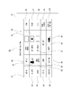
- the camera control unit 11 detects whether the retractable cylinder 21 is in the retracted state or the extended state, and if it is in the retracted state, the setting list 80 as shown in FIG. 2 is displayed on the display unit 13. It shall be processed.
- This setting list 80 is an example as a display of various setting information of the image pickup apparatus 1, and is a collection of modes and parameters as a plurality of setting information that should be confirmed by the user especially when preparing for imaging. Is. As shown in the figure, the contents of the setting information include aperture priority mode 81, exposure compensation mode 82, shutter speed 83, F value 84, ISO sensitivity 85, autofocus mode 86, face detection mode 87, and high dynamic range mode 88.
- Auto white balance 89 image stabilization mode 90, single / continuous shooting mode 91, AE area 92, AF area 93, picture profile setting 94, battery level 95, still image recording size 96, image quality mode 97, aspect ratio 98, Each display as a recorded image type 99 and a moving image recording format 100 is included. Of course, these are just examples.
- FIG. 3 shows a processing example of the camera control unit 11 for displaying such a setting list 80.
- the camera control unit 11 confirms whether the lens barrel 2 side is currently in the retracted state or the extended state. As described above, the analog signal from the zoom / retractable position sensor 27 is converted into a digital signal by the A / D converter 24, and the lens control unit 22 detects either the retracted state or the extended state. Then, the lens control unit 22 periodically transmits information on the stored state / extended state to the camera control unit 11 by lens-body communication. In step S101, the camera control unit 11 confirms the information from the lens control unit 22.
- step S102 controls the graphic processing unit 19 for setting display for storage. That is, the graphic processing unit 19 is instructed to display the setting list 80 as shown in FIG. 2, for example. As a result, the display unit 13 displays the setting list 80.
- the detection content is switched from the immediately before feeding state to the stored state, an instruction to end the display of the through image displayed up to that time is also given.
- step S101 when the camera control unit 11 detects that it is in the feeding state in step S101, the camera control unit 11 proceeds from step S101 to step S103 to control the through image display.
- step S103 When the detection content is switched from the immediately preceding stored state to the extended state, an instruction is also given to end the display of the setting list 80 displayed up to that point.
- the setting list 80 as shown in FIG. 2 is displayed in the stored state, and the through image is displayed in the extended state.
- the stored state is not suitable for imaging, but in that case, the user can confirm the setting state from the setting list 80.
- the user turns the zoom operation ring 26 to bring it into the extended state.
- the display of the setting list 80 is finished and the through image is displayed, so that the display unit 13 is in a state suitable for monitoring the subject at the time of imaging.
- FIG. 4 shows a processing example of the camera control unit 11.
- step S101 the camera control unit 11 confirms whether the lens barrel 2 side is currently in the retracted state or the extended state.
- step S101 When the camera control unit 11 detects that it is in the feeding state in step S101, the camera control unit 11 proceeds from step S101 to step S115 to control the through image display.
- step S115 When the detection content is switched from the immediately preceding stored state to the extended state, an instruction is also given to end the display of the setting list 80 displayed up to that point.
- step S101 When the camera control unit 11 detects that the storage state is stored in step S101, the camera control unit 11 proceeds to step S102 and controls the graphic processing unit 19 for setting display control for storage. That is, the graphic processing unit 19 is instructed to display the setting list 80 as shown in FIG. 2, for example.
- the detection content is switched from the immediately before feeding state to the stored state, an instruction to end the display of the through image displayed up to that time is also given.
- each display content of the setting list 80 in FIG. 2 is an icon for changing the setting, and can be specified by the user by a touch operation or a cursor operation.
- a setting item called "F value” by touching the display area of the F value 84 in the setting list 80.
- a setting item called "shutter speed” by touching the display area of the F value 84 in the setting list 80.
- the camera control unit 11 repeats the confirmation in step S101, and if the stored state is continued, the processes in steps S102 and S110 are repeated. That is, the display of the setting list 80 is continued.
- the camera control unit 11 proceeds from step S101 to step S115, and switches the display from the setting list 80 to the through image. .. After that, if the feeding state is continued, the display of the through image is continued.
- step S110 When it is detected that the user has performed a designated operation on the display of the setting list 80, the camera control unit 11 proceeds from step S110 to step S111, and transitions to a screen for changing the setting of the corresponding item in the menu hierarchy.
- Display control as follows.
- the menu of the image pickup apparatus 1 has a structure in which, for example, a major category of items is presented on the first screen of the menu, and the item selection reaches a screen for changing more subdivided items in the lower hierarchy.
- step S111 display control is performed so as to directly transition to the change screen of the designated setting item in such a menu structure.
- a menu hierarchy structure there are major classification items such as "operation setting", "shooting setting", "still image setting", etc.
- the shutter speed is in the lower hierarchy of one or more steps of "shooting setting". It is assumed that the change screen of is provided. In this case, when the user performs an operation of designating the display area of the shutter speed 83 of the setting list 80, the screen directly transitions to the shutter speed change screen in the menu structure. That is, in the setting list 80, each displayed item functions as a shortcut key to the setting change screen.
- the camera control unit 11 monitors the user's setting change operation in step S113 while checking the stored state / extended state in step S112. If it is detected that the user operates the zoom operation ring 26 to enter the feeding state, the camera control unit 11 proceeds from step S112 to step S115, ends the display of the item change screen in the menu, and performs a through image. Will be switched to. After that, if the feeding state is continued, the display of the through image is continued.
- step S113 When the camera control unit 11 detects the user's setting change operation in step S113 while the camera control unit 11 displays the change screen of a certain setting item, the process proceeds to step S114 to reflect the setting change. That is, the process of changing the mode and parameters of the operated setting items is performed. Then, the process proceeds to steps S101 and S102 to return to the display state of the setting list 80.
- the user can not only confirm the setting from the setting list 80 but also specify the item to be changed and change the setting extremely easily. Therefore, the stored state, that is, imaging Suitable as a user interface in preparation.
- the setting list 80 and the change screen are terminated and switched to the through image by extending the lens, it is possible to immediately transition to the image capable state even if confirmation is performed, which is also suitable in that a photo opportunity is not missed. It becomes.
- Non-operation standby means a state in which no operation is performed by the user and no continuous operation such as video recording or video playback is in progress.
- the setting list 80 and the change screen of the second embodiment are continuously displayed when in the stored state, and the through image display is continuously displayed in the extended state. However, this corresponds to the period during which no operation, recording operation, or video playback operation is performed.
- the camera control unit 11 turns off the standby flag F1 in step S210.
- step S202 the camera control unit 11 proceeds to step S202, confirms the standby flag F1, resets the timer TM to “0” in step S203 if the standby flag F1 is not on, and waits flag F1. Is turned on. If the waiting flag F1 is already on when the process proceeds to step S202 during non-operation standby, the camera control unit 11 increments the timer TM in step S205. Therefore, the timer TM count starts from the time when the non-operation standby is set, and the count is increased for the period during which the non-operation standby continues.
- the camera control unit 11 determines the stored state / extended state in step S206 and branches the process. If it is in the retracted state, the camera control unit 11 proceeds to step S207 and determines whether or not the timer TM has reached the threshold value th1. If it has not been reached, the process returns to step S201, but if it has been reached, the process proceeds to step S209 to control the power off.
- step S206 When it is determined in step S206 that it is in the feeding state, the camera control unit 11 proceeds to step S208 and determines whether or not the timer TM has reached the threshold value th2. If it has not been reached, the process returns to step S201, but if it has been reached, the process proceeds to step S209 to control the power off.
- the power off control is automatically performed by continuing the non-operation standby in both the retracted state and the extended state.
- the threshold values th1 and th2 are set to th1 ⁇ th2.
- the threshold value th1 is equivalent to 30 seconds
- the threshold value th2 is equivalent to 1 minute, and the like. Therefore, in the retracted state, the duration of the non-operation standby in which the power is turned off is shorter than in the extended state.
- Extending interlocking recording is a function that starts video recording when the camera system is in the mode of recording video, and when the camera system is in the feeding state from the stored state. Further, the moving image recording may be stopped when the state is changed from the extended state to the stored state.
- the camera control unit 11 also makes a display suitable for the feed-out interlocking recording.
- step S301 the process is branched depending on whether or not the moving image recording mode is set.
- the moving image recording mode is a mode that can be selected by the user, for example, with a dial operator (not shown) provided on the camera body 10.
- the processes after step S302 are executed.
- the camera control unit 11 turns on the interlocking reservation flag F2 in step S302.
- the interlocking reservation flag F2 is a flag indicating whether or not the advance interlocking recording function is valid or invalid.
- the interlocking reservation flag F2 is turned on, assuming that the advance interlocking recording is enabled by default.
- a processing example in which the interlocking reservation flag F2 is turned off that is, a processing example in which the advance interlocking recording is disabled by default can be considered.
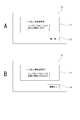
- step S303 the camera control unit 11 determines the retracted state / extended state. If it is in the stored state, the camera control unit 11 proceeds to step S304 and branches the process depending on whether or not the moving image is currently being recorded. Then, if the moving image is not being recorded, the camera control unit 11 proceeds to step S305 and instructs the graphic processing unit 19 to execute the display related to the interlocking function. For example, the camera control unit 11 displays the interlocking function state presentation image 70 as shown in FIG. 7A or FIG. 7B.
- the interlocking function state presentation image 70 of FIG. 7A includes a valid message 71 and a release button 72.
- the interlocking function state presentation image 70 of FIG. 7B includes an invalid message 73 and an interlocking button 74.
- the camera control unit 11 instructs the graphic processing unit 19 to execute the display of FIG. Notify that In addition, the user can disable the pay-out interlocking recording by operating the release button 72.
- the camera control unit 11 When it is detected that the user has operated the release button 72, the camera control unit 11 proceeds from step S306 to step S307 to turn off the interlocking reservation flag F2. Then, the process proceeds to steps S303, S304, and S305. In that case, the camera control unit 11 instructs the graphic processing unit 19 to execute the display of FIG. 7B, and notifies the user that the feed-out interlocking recording is invalid. Further, the user can enable the advance interlocking recording by operating the interlocking button 74.
- step S306 the camera control unit 11 proceeds from step S306 to step S307 and turns on the interlocking reservation flag F2. Then, the process proceeds to steps S303, S304, and S305. In that case, the display of FIG. 7A will be executed again.
- the camera control unit 11 when in the stored state, causes the display unit 13 to display the interlocking function state presentation image 70, presents the user with the enable / disable of the feed-out interlocking recording, and enables / disables the operation. Is possible.
- the camera control unit 11 When it is detected in step S303 that it is in the feeding state, the camera control unit 11 confirms the pause flag F3 in step S320.
- the pause flag F3 is a flag indicating a recording pause (REC pause) state.
- the camera control unit 11 proceeds to step S321, and confirms the interlocking reservation flag F2. If the interlocking reservation flag F2 is on, the camera control unit 11 sets (or continues to turn off) the pause flag F3 in step S322, and controls to start moving image recording in step S323. That is, when the extension interlocking recording is enabled and the user operates the zoom operation ring 26 to extend the retractable cylinder 21, the moving image recording is automatically started.
- the camera control unit 11 After the moving image recording is started, the camera control unit 11 performs the loop processing of steps S330, S340, S303, S320, S321, S322, and S323, and during this period, the moving image recording is continued in step S323.
- step S303 If the user operates the zoom operation ring 26 to store the retractable cylinder 21 during the moving image recording, the moving image recording is stopped. That is, if the stored state is detected in step S303 during moving image recording, the camera control unit 11 proceeds from step S304 to step S310 to stop moving image recording. Further, the pause flag F3 is turned off in step S311. Then, the camera control unit 11 proceeds to step S305 and controls the display of the interlocking function state presentation image 70 as described above. Therefore, the user can start and stop the recording only by operating the zoom operation ring 26.
- the processing of the camera control unit 11 proceeds to steps S303, S320, and S324 according to the extension operation of the user, and in step S324, the recording is paused (REC pause). That is, it is in a standby state until the start operation of moving image recording. Then, in step S325, the pause flag F3 is turned on.
- the camera control unit 11 monitors the stop operation of the user in step S330, particularly the stop operation other than the zoom operation ring 26 in this case. For example, as an operation of the recording operator 18, the operation of stopping the recording by the user is monitored.
- the camera control unit 11 proceeds to step S324, stops the moving image recording, and puts the recording pause (REC pause) state. That is, it is in a standby state until the start operation of moving image recording.
- the pause flag F3 is turned on.
- the process proceeds to steps S330, S340, S303, and S320, and since the pause flag F3 is on, the process proceeds to step S324.
- the recording pause state is continued in step S324, and the on state of the pause flag F3 is maintained in step S325.
- the user can start video recording by operating the recording controller 18.
- the camera control unit 11 recognizes it as a recording start operation in step S340, proceeds to step S322 to turn off the pause flag F3, and controls to start moving image recording in step S323. conduct.
- the user can start and stop the moving image recording by operating the zoom operation ring 26, and can also start and stop the moving image recording by the recording operator 18, which improves the usability of the user. NS.
- the image pickup apparatus 1 of the embodiment is a lens mirror having a retractable tubular body 21 capable of manually operating a tubular body holding at least one or more lenses with respect to the lens barrel main body 20.
- a camera body 10 to which the cylinder 2 can be mounted is provided.
- the image pickup device 1 includes a camera control unit 11 that controls to display information indicating the state of the image pickup device 1 when it detects that the lens barrel 2 mounted on the camera body 10 is in the retracted state. ing.
- the lens barrel 2 is in the retracted state, it is in a state where proper imaging cannot be performed, but it can be considered that it is in a standby state for imaging.
- displaying information indicating the state of the image pickup apparatus 1 on the display unit 13 and letting the user recognize the state is an appropriate information display for preparation before imaging.
- the user can make appropriate preparations (change the mode of the image pickup device 1, adjust the brightness of the subject, select the shooting environment, etc.) as necessary, and then make appropriate preparations. It is also desirable in terms of avoiding shooting failures.
- the fact that, for example, the setting list 80 and the interlocking function state presentation image 70 are displayed in the stored state as information indicating the state of the image pickup apparatus 1, for the user, conversely, the lens mirror is displayed by displaying the setting list 80 and the like. It is also easy to recognize that the cylinder 2 is in the stored state. In other words, it also motivates the user to perform the extension operation of the lens barrel.
- the setting list 80, the interlocking function state presentation image 70, and the like are displayed in the stored state, but these displays are displayed according to the user's preference. It may be possible to choose not to do so.
- the information indicating the state of the image pickup apparatus 1 is displayed on the display unit 13 provided in the camera body 10, it may be displayed on a display device separate from the camera body 10.
- the display unit 13 may be configured not only as a display unit such as a liquid crystal panel provided on the camera body 10 but also as a viewfinder.
- the camera control unit 11 gives an example of performing control to display setting information as information indicating the state of the image pickup apparatus 1.
- the setting information for example, the setting list 80 is displayed in the stored state, so that the user can use the current setting of the imaging device 1, such as aperture priority mode, exposure compensation mode, shutter speed, F value, and ISO sensitivity at the timing before imaging. You can check the camera settings that are important to the user at the time of imaging. Therefore, it is a useful information display at the timing immediately before the actual imaging.
- the setting list 80 is given as an example of displaying the setting information, it is not always necessary to display a list of a plurality of settings. The state of at least one setting may be displayed.
- the user may be able to select the setting information to be displayed in advance. This is because it is useful for users who often change a specific setting in use to be able to check the setting.
- the camera control unit 11 ends the display of the setting information in response to the detection of the feeding state while displaying the setting information in response to the detection of the stored state. It was decided to control the operation.
- the display of the setting list 80 showing the setting information is finished and, for example, the through image can be appropriately visually recognized, the user can be made to recognize that the image is in an appropriate state by extending the lens. It is easy for the user to recognize the state in which it is okay to take an image, which is convenient. Further, when the display of the setting list 80 disappears, the through image of the subject is displayed in an easy-to-see manner on the screen of the display unit 13, and it can be said that the display state is suitable for imaging.
- the camera control unit 11 controls to display the setting information and hide the through image of the captured image in response to the detection of the stored state, and the feeding state is detected.
- an example is given in which the display of the setting information is terminated and the control for displaying the through image of the captured image is performed.
- the display of the setting list 80 showing the setting information and displaying the through image
- the through image in the blurred state in the stored state is not displayed, and the display as the image pickup apparatus 1 is performed. It is also possible not to lower the dignity.
- the appearance of the through image in the extended state makes the user naturally recognize that the image is in the imaging state.
- the through image may be displayed even in the stored state.
- the display of the setting list 80 is the main display, and the quality of the through image is not questioned. You may do so.
- the camera control unit 11 gives an example of performing the setting change process in response to the detection of a predetermined operation when displaying the setting information. For example, when the user selects a setting item from the setting list 80 by a touch operation, a cursor operation, or the like, the screen transitions to the operation screen of the selected setting item (step S111 in FIG. 4). Then, if there is a setting change operation, the setting change process is performed (steps S113 and S114). As a result, when it is in the stored state, it is possible to easily change any setting while checking the setting in the setting list 80.
- the camera control unit 11 displays a change screen in the menu hierarchy of the designated setting information in response to the detection of the designated operation for displaying the setting information, and detects the operation for the change screen.
- An example of performing the setting change processing according to the above is given.
- the item hierarchy is followed from the menu screen to reach the change screen of an arbitrary setting item, whereas the change screen is directly reached from the setting list 80.
- the setting list 80 has a role as a shortcut icon that can be used when it is in the stored state, and it is possible to change the setting of an arbitrary item while checking the setting at the stage of preparation for imaging. It is extremely easy to do, and the usability of the user is greatly improved.
- the camera control unit 11 ends the display of the change screen in response to the detection of the feeding state when the change screen is displayed in the stored state, and captures an image.
- An example of controlling the display of the through image of the camera is given. Even when the change screen in the menu item is displayed by transitioning from the setting list 80, the change screen display in which the user has extended the lens is terminated, and the subject can be confirmed by the through image. As a result, even when the lens barrel is in the menu hierarchy, the lens barrel can be extended to immediately transition to the image-capable state. It is also effective in the sense that you will not miss a photo opportunity in the ready state where you are changing the settings in the stored state.
- the display of the change screen is finished and the through image is displayed, it also means that the user is made to recognize that an appropriate image can be taken by extending the lens. Furthermore, even if the user enters the menu once, he / she can easily exit the menu by extending the lens barrel, so that the operability is improved.
- the camera control unit 11 controls to display information related to an interlocking function in which moving image recording is controlled according to the retracted state and the extended state of the lens barrel as information indicating the state of the image pickup device 1.
- the collapsible cylinder 21 has an interlocking function (feeding interlocking recording) in which moving image recording is started in response to the feeding, the interlocking function state presentation image 70 is displayed as a display related to the function.
- the interlocking function state presentation image 70 is displayed as a display related to the function.
- Appropriate moving image recording cannot be performed in the stored state, and it can be said that it is a preparation period when the moving image recording is also in the stored state.
- the user can operate the zoom operation ring 26 by displaying the information as to whether or not the pay-out interlocking recording is reserved in the stored state. This makes it possible to appropriately recognize whether or not the pay-out interlocking recording is activated. Therefore, the user can appropriately recognize the operation method for moving image recording. It is also possible to present a suitable feed-out interlocking recording to a user who wants not to miss a photo opportunity.
- the camera control unit 11 gives an example of controlling to start moving image recording according to the extended state of the lens barrel 2.
- the extension interlocking recording function is enabled (interlocking reservation flag F2 is turned on)
- video recording is started only by extending the lens, so this function is very in the sense that you will not miss a recording opportunity. It will be useful.
- two actions are required: the lens is extended and then the recording start operation is performed with the record button or the like.
- recording is started only by operating the zoom operation ring 26. Therefore, it becomes easy for the cameraman to immediately respond to the recording start chance.
- the camera control unit 11 when the camera control unit 11 starts the moving image recording by the interlocking function, the camera control unit 11 controls to stop the moving image recording according to the stored state of the lens barrel 2.
- the operation mode of stopping the moving image recording by storing the lens makes it possible to provide a very easy-to-understand operation.
- stopping the video recording when the stored state is reached is a desirable process from the viewpoint of maintaining the quality of the recorded video. ..
- the camera control unit 11 may activate only the moving image recording stop as an interlocking function.
- the start of moving image recording is solely performed by the operation of the recording controller 18.
- the recording stop control is performed. In this way, it is possible to prevent recording of a low-quality moving image due to the stored state.
- the camera control unit 11 displays information about the interlocking function and a display that enables an on / off operation of the interlocking function, for example, a display of the release button 72 of FIG. 7A and the interlocking button 74 of FIG. 7B.
- a display that enables an on / off operation of the interlocking function for example, a display of the release button 72 of FIG. 7A and the interlocking button 74 of FIG. 7B.
- An example of controlling the execution of As a result the user can select on / off of the interlocking function such that the moving image recording is started according to the extension of the retractable lens.
- a user interface that not only presents the reserved state of feed-in interlocking recording in the stored state but also allows the reserved state to be turned on / off, that is, when the user is in the stored state, that is, while waiting for imaging for the user.
- the function of the feeding-linked recording can be appropriately selected, and the usability of the feeding-linked recording function is improved.
- the camera control unit 11 indicates information indicating the state of the image pickup apparatus 1 according to the case where the stored state continues for the first predetermined time (time corresponding to the threshold value th1) or more in the non-operation standby state.
- An example of controlling the power off while ending the display of is shown. Displaying information indicating the state of the image pickup apparatus 1 (for example, information on setting information and interlocking functions) in the stored state is useful as described above, but displaying it continuously indefinitely is power consumption. It is wasted in terms of consumption. Therefore, the display is terminated at the first predetermined time, and the power is turned off.
- the camera control unit 11 controls to turn off the power according to the continuation of the non-operation standby for the second predetermined time (time corresponding to the threshold value th2) or more even in the feeding state.
- the first predetermined time is shorter than the second predetermined time. That is, the power is turned off after a lapse of time without operation in both the extended state and the stowed state, but the power is turned off earlier in the stowed state. Since the stored state is waiting for the user, it is possible that the user is not using the stored state, and it is not desirable to continue the display for a long time. Therefore, the time at which the threshold values th1 and th2 in FIG. 6 are reached is set to th1 ⁇ th2, and the power is turned off early when the non-operation is continued in the stored state. This suppresses power consumption in the stored state.
- a camera body to which a lens barrel having a retractable barrel that holds at least one lens can be manually operated to be retracted and extended with respect to the lens barrel.
- An image pickup device including a control unit that controls to display information indicating the state of the image pickup device when it detects that the lens barrel mounted on the camera body is in the retracted state.
- the control unit The imaging device according to (1) above, which controls display of setting information as information indicating the state of the imaging device.
- the control unit The imaging device according to (2) above, which controls to end the display of the setting information in response to the detection of the feeding state while displaying the setting information in response to the detection of the stored state. ..
- the control unit In response to the detection of the stored state, the setting information is displayed and the through image of the captured image is controlled to be hidden.
- the imaging device according to (2) or (3) above wherein the display of the setting information is terminated and control is performed to display a through image of the captured image in response to the detection of the feeding state.
- the control unit The imaging device according to any one of (2) to (4) above, which performs a setting change process in response to detection of a predetermined operation when displaying the setting information.
- the control unit In response to the detection of the specified operation for displaying the setting information, the change screen in the menu hierarchy of the specified setting information is displayed, and the setting change process is performed according to the detection of the operation for the change screen.
- the imaging device according to any one of (5).
- the control unit When the change screen is displayed in the stored state, the display of the change screen is terminated and the through image of the captured image is displayed in response to the detection of the feeding state.
- the image pickup apparatus according to (6).
- the control unit The imaging device according to (1) above, which controls to display information on an interlocking function in which moving image recording is controlled according to a retracted state and a feeding state of the lens barrel as information indicating a state of the imaging device.
- the control unit When the interlocking function is enabled
- the imaging device according to (8) above which controls the start of moving image recording according to the extended state of the lens barrel.
- the control unit When video recording is started by the interlocking function, The imaging device according to (9) above, which controls to stop moving image recording according to the stored state of the lens barrel. (11) The control unit The imaging device according to any one of (8) to (10) above, which controls to execute a display that enables an on / off operation of the interlocking function together with information about the interlocking function. (12) The control unit When the stored state continues for the first predetermined time or longer while waiting for no operation, the display of the information indicating the state of the imaging device is terminated and the power is turned off. The imaging device according to any one of 11). (13) The control unit In the feeding state, control is performed to turn off the power according to the continuation of the second predetermined time or more while waiting by non-operation.
- the imaging device according to (12) above, wherein the first predetermined time is shorter than the second predetermined time.
- Imaging with a camera body to which a lens barrel with a retractable barrel that holds at least one lens can be manually operated to be retracted and extended with respect to the lens barrel.
- the device is An imaging method that controls to display information indicating the status of an imaging device when it detects that the lens barrel mounted on the camera body is in the retracted state.
- Imaging device Lens lens barrel 10
- Camera body 11 Camera control unit 12
- Image signal processing unit 13 Display unit 14
- Image sensor 15 Recording unit 16
- Power controller 18 Recording controller 19
- Graphic processing unit 20 Lens barrel body 21 Collapsed cylinder 22
- Lens control unit 26 Zoom operation ring 27
- Setting list
Landscapes
- Engineering & Computer Science (AREA)
- Multimedia (AREA)
- Signal Processing (AREA)
- Physics & Mathematics (AREA)
- General Physics & Mathematics (AREA)
- Human Computer Interaction (AREA)
- Optics & Photonics (AREA)
- Studio Devices (AREA)
- Structure And Mechanism Of Cameras (AREA)
Priority Applications (3)
| Application Number | Priority Date | Filing Date | Title |
|---|---|---|---|
| CN202180021912.5A CN115299035B (zh) | 2020-03-25 | 2021-02-15 | 成像设备和成像方法 |
| JP2022509398A JP7571784B2 (ja) | 2020-03-25 | 2021-02-15 | 撮像装置、撮像方法 |
| US17/906,646 US12323697B2 (en) | 2020-03-25 | 2021-02-15 | Imaging device and imaging method |
Applications Claiming Priority (2)
| Application Number | Priority Date | Filing Date | Title |
|---|---|---|---|
| JP2020053687 | 2020-03-25 | ||
| JP2020-053687 | 2020-03-25 |
Publications (1)
| Publication Number | Publication Date |
|---|---|
| WO2021192724A1 true WO2021192724A1 (ja) | 2021-09-30 |
Family
ID=77890321
Family Applications (1)
| Application Number | Title | Priority Date | Filing Date |
|---|---|---|---|
| PCT/JP2021/005520 Ceased WO2021192724A1 (ja) | 2020-03-25 | 2021-02-15 | 撮像装置、撮像方法 |
Country Status (4)
| Country | Link |
|---|---|
| US (1) | US12323697B2 (https=) |
| JP (1) | JP7571784B2 (https=) |
| CN (1) | CN115299035B (https=) |
| WO (1) | WO2021192724A1 (https=) |
Cited By (1)
| Publication number | Priority date | Publication date | Assignee | Title |
|---|---|---|---|---|
| US12167131B2 (en) * | 2021-11-11 | 2024-12-10 | Canon Kabushiki Kaisha | Image capturing apparatus capable of controlling continuous photographing according to motion of an object and shake information, method of controlling same, and storage medium |
Citations (4)
| Publication number | Priority date | Publication date | Assignee | Title |
|---|---|---|---|---|
| JPH06186629A (ja) * | 1992-12-17 | 1994-07-08 | Nikon Corp | 日付表示機能付カメラ |
| JP2007096646A (ja) * | 2005-09-28 | 2007-04-12 | Fujifilm Corp | 撮影装置 |
| JP2007194769A (ja) * | 2006-01-18 | 2007-08-02 | Olympus Imaging Corp | デジタル一眼レフカメラ |
| JP2018045246A (ja) * | 2017-11-06 | 2018-03-22 | 株式会社ニコン | 撮像装置及びカメラボディ |
Family Cites Families (6)
| Publication number | Priority date | Publication date | Assignee | Title |
|---|---|---|---|---|
| JP2001320610A (ja) * | 2000-05-02 | 2001-11-16 | Nikon Corp | 電子スチルカメラ |
| JP2010103599A (ja) | 2008-10-21 | 2010-05-06 | Olympus Imaging Corp | デジタルカメラシステム、デジタルカメラ、および交換レンズ |
| JP5402857B2 (ja) | 2010-07-05 | 2014-01-29 | 株式会社ニコン | 撮像装置及びレンズ鏡筒 |
| JP2014077878A (ja) | 2012-10-10 | 2014-05-01 | Sony Corp | レンズ鏡筒及び撮像装置 |
| JP6031680B2 (ja) * | 2013-03-26 | 2016-11-24 | パナソニックIpマネジメント株式会社 | 撮像装置、カメラボディ、撮像装置の制御方法 |
| JP2015079042A (ja) | 2013-10-15 | 2015-04-23 | パナソニック株式会社 | 交換レンズ、カメラシステム |
-
2021
- 2021-02-15 US US17/906,646 patent/US12323697B2/en active Active
- 2021-02-15 CN CN202180021912.5A patent/CN115299035B/zh active Active
- 2021-02-15 WO PCT/JP2021/005520 patent/WO2021192724A1/ja not_active Ceased
- 2021-02-15 JP JP2022509398A patent/JP7571784B2/ja active Active
Patent Citations (4)
| Publication number | Priority date | Publication date | Assignee | Title |
|---|---|---|---|---|
| JPH06186629A (ja) * | 1992-12-17 | 1994-07-08 | Nikon Corp | 日付表示機能付カメラ |
| JP2007096646A (ja) * | 2005-09-28 | 2007-04-12 | Fujifilm Corp | 撮影装置 |
| JP2007194769A (ja) * | 2006-01-18 | 2007-08-02 | Olympus Imaging Corp | デジタル一眼レフカメラ |
| JP2018045246A (ja) * | 2017-11-06 | 2018-03-22 | 株式会社ニコン | 撮像装置及びカメラボディ |
Cited By (1)
| Publication number | Priority date | Publication date | Assignee | Title |
|---|---|---|---|---|
| US12167131B2 (en) * | 2021-11-11 | 2024-12-10 | Canon Kabushiki Kaisha | Image capturing apparatus capable of controlling continuous photographing according to motion of an object and shake information, method of controlling same, and storage medium |
Also Published As
| Publication number | Publication date |
|---|---|
| US20230133045A1 (en) | 2023-05-04 |
| JPWO2021192724A1 (https=) | 2021-09-30 |
| CN115299035A (zh) | 2022-11-04 |
| CN115299035B (zh) | 2025-09-12 |
| JP7571784B2 (ja) | 2024-10-23 |
| US12323697B2 (en) | 2025-06-03 |
Similar Documents
| Publication | Publication Date | Title |
|---|---|---|
| KR100731192B1 (ko) | 촬상장치 및 그 제어 방법 | |
| CN106256121B (zh) | 成像装置 | |
| US9671932B2 (en) | Display control apparatus and control method thereof | |
| JP4140231B2 (ja) | 撮像装置及びそのプログラム | |
| US20100026873A1 (en) | Digital image processing apparatuses, methods of controlling the same, and computer-readable medium encoded with computer executable instructions for executing the method(s) | |
| JP2015227902A (ja) | 撮像装置 | |
| JP2015227901A (ja) | 撮像装置 | |
| JP2013255203A (ja) | 撮像装置およびその制御方法、プログラム並びに記憶媒体 | |
| CN103248801B (zh) | 摄像装置 | |
| CN115299035B (zh) | 成像设备和成像方法 | |
| JP6071441B2 (ja) | 撮像装置及びその制御方法、プログラム | |
| KR101650930B1 (ko) | 휴대단말기에 구비된 카메라 인터페이스의 설정 시스템 | |
| JP6410778B2 (ja) | 撮像装置及びその制御方法 | |
| JP4724512B2 (ja) | 撮像装置、制御方法、制御プログラム及び記憶媒体 | |
| JP6758843B2 (ja) | 撮影制御装置およびその制御方法 | |
| US20200221035A1 (en) | Display control apparatus and control method therefor | |
| JP4534176B2 (ja) | 電子カメラ | |
| JP7183110B2 (ja) | 撮像装置、その制御方法及びプログラム | |
| US12292775B2 (en) | Electronic apparatus, method of controlling the same and non-transitory computer-readable storage medium | |
| JP2015055775A (ja) | 撮像装置および撮像装置の制御方法 | |
| JP2018074216A (ja) | 電子機器 | |
| JP2006080978A (ja) | 写真撮影システム | |
| KR101314827B1 (ko) | 디지털 촬영장치의 제어방법 및 이 방법을 채용한 디지털촬영장치 | |
| KR101058017B1 (ko) | 디지털 촬영 장치의 메뉴 표시 제어 방법 및 이 방법을채용한 디지털 촬영 장치 | |
| JP2007318535A (ja) | カメラ |
Legal Events
| Date | Code | Title | Description |
|---|---|---|---|
| 121 | Ep: the epo has been informed by wipo that ep was designated in this application |
Ref document number: 21775962 Country of ref document: EP Kind code of ref document: A1 |
|
| ENP | Entry into the national phase |
Ref document number: 2022509398 Country of ref document: JP Kind code of ref document: A |
|
| NENP | Non-entry into the national phase |
Ref country code: DE |
|
| 122 | Ep: pct application non-entry in european phase |
Ref document number: 21775962 Country of ref document: EP Kind code of ref document: A1 |
|
| WWG | Wipo information: grant in national office |
Ref document number: 17906646 Country of ref document: US |
|
| WWG | Wipo information: grant in national office |
Ref document number: 202180021912.5 Country of ref document: CN |