WO2021192664A1 - 二次電池 - Google Patents
二次電池 Download PDFInfo
- Publication number
- WO2021192664A1 WO2021192664A1 PCT/JP2021/004624 JP2021004624W WO2021192664A1 WO 2021192664 A1 WO2021192664 A1 WO 2021192664A1 JP 2021004624 W JP2021004624 W JP 2021004624W WO 2021192664 A1 WO2021192664 A1 WO 2021192664A1
- Authority
- WO
- WIPO (PCT)
- Prior art keywords
- positive electrode
- current collector
- tab
- electrode body
- plate
- Prior art date
Links
- 238000004804 winding Methods 0.000 claims abstract description 30
- 238000007789 sealing Methods 0.000 claims description 40
- 239000010410 layer Substances 0.000 description 24
- 239000011255 nonaqueous electrolyte Substances 0.000 description 18
- 239000002002 slurry Substances 0.000 description 18
- 238000003466 welding Methods 0.000 description 18
- 239000007774 positive electrode material Substances 0.000 description 13
- 239000011241 protective layer Substances 0.000 description 13
- 238000000034 method Methods 0.000 description 11
- 239000007773 negative electrode material Substances 0.000 description 11
- SECXISVLQFMRJM-UHFFFAOYSA-N N-Methylpyrrolidone Chemical compound CN1CCCC1=O SECXISVLQFMRJM-UHFFFAOYSA-N 0.000 description 10
- 239000002033 PVDF binder Substances 0.000 description 6
- 229920002981 polyvinylidene fluoride Polymers 0.000 description 6
- RYGMFSIKBFXOCR-UHFFFAOYSA-N Copper Chemical compound [Cu] RYGMFSIKBFXOCR-UHFFFAOYSA-N 0.000 description 5
- 229910052782 aluminium Inorganic materials 0.000 description 5
- XAGFODPZIPBFFR-UHFFFAOYSA-N aluminium Chemical compound [Al] XAGFODPZIPBFFR-UHFFFAOYSA-N 0.000 description 5
- 239000003575 carbonaceous material Substances 0.000 description 5
- 239000008151 electrolyte solution Substances 0.000 description 5
- 238000005452 bending Methods 0.000 description 4
- 239000011230 binding agent Substances 0.000 description 4
- 229910052802 copper Inorganic materials 0.000 description 4
- 239000010949 copper Substances 0.000 description 4
- 238000010586 diagram Methods 0.000 description 4
- 238000002347 injection Methods 0.000 description 4
- 239000007924 injection Substances 0.000 description 4
- 238000004519 manufacturing process Methods 0.000 description 4
- 238000002360 preparation method Methods 0.000 description 4
- 239000004020 conductor Substances 0.000 description 3
- 230000006866 deterioration Effects 0.000 description 3
- 239000002612 dispersion medium Substances 0.000 description 3
- 230000000694 effects Effects 0.000 description 3
- 230000001678 irradiating effect Effects 0.000 description 3
- 229910052751 metal Inorganic materials 0.000 description 3
- 239000002184 metal Substances 0.000 description 3
- XLYOFNOQVPJJNP-UHFFFAOYSA-N water Substances O XLYOFNOQVPJJNP-UHFFFAOYSA-N 0.000 description 3
- OKTJSMMVPCPJKN-UHFFFAOYSA-N Carbon Chemical compound [C] OKTJSMMVPCPJKN-UHFFFAOYSA-N 0.000 description 2
- 229920002134 Carboxymethyl cellulose Polymers 0.000 description 2
- XEEYBQQBJWHFJM-UHFFFAOYSA-N Iron Chemical compound [Fe] XEEYBQQBJWHFJM-UHFFFAOYSA-N 0.000 description 2
- PNEYBMLMFCGWSK-UHFFFAOYSA-N aluminium oxide Inorganic materials [O-2].[O-2].[O-2].[Al+3].[Al+3] PNEYBMLMFCGWSK-UHFFFAOYSA-N 0.000 description 2
- 230000015572 biosynthetic process Effects 0.000 description 2
- 239000002131 composite material Substances 0.000 description 2
- 239000003792 electrolyte Substances 0.000 description 2
- 229910002804 graphite Inorganic materials 0.000 description 2
- 239000010439 graphite Substances 0.000 description 2
- 239000000843 powder Substances 0.000 description 2
- 239000011347 resin Substances 0.000 description 2
- 229920005989 resin Polymers 0.000 description 2
- 229920003048 styrene butadiene rubber Polymers 0.000 description 2
- 239000002174 Styrene-butadiene Substances 0.000 description 1
- SOXUFMZTHZXOGC-UHFFFAOYSA-N [Li].[Mn].[Co].[Ni] Chemical compound [Li].[Mn].[Co].[Ni] SOXUFMZTHZXOGC-UHFFFAOYSA-N 0.000 description 1
- 239000001768 carboxy methyl cellulose Substances 0.000 description 1
- 235000010948 carboxy methyl cellulose Nutrition 0.000 description 1
- 239000008112 carboxymethyl-cellulose Substances 0.000 description 1
- 239000000919 ceramic Substances 0.000 description 1
- MZZUATUOLXMCEY-UHFFFAOYSA-N cobalt manganese Chemical compound [Mn].[Co] MZZUATUOLXMCEY-UHFFFAOYSA-N 0.000 description 1
- 238000007796 conventional method Methods 0.000 description 1
- 239000011889 copper foil Substances 0.000 description 1
- 239000011888 foil Substances 0.000 description 1
- 229910052742 iron Inorganic materials 0.000 description 1
- 238000005304 joining Methods 0.000 description 1
- RSNHXDVSISOZOB-UHFFFAOYSA-N lithium nickel Chemical compound [Li].[Ni] RSNHXDVSISOZOB-UHFFFAOYSA-N 0.000 description 1
- 229920000098 polyolefin Polymers 0.000 description 1
- 238000010248 power generation Methods 0.000 description 1
- 230000001105 regulatory effect Effects 0.000 description 1
Images


Classifications
-
- H—ELECTRICITY
- H01—ELECTRIC ELEMENTS
- H01M—PROCESSES OR MEANS, e.g. BATTERIES, FOR THE DIRECT CONVERSION OF CHEMICAL ENERGY INTO ELECTRICAL ENERGY
- H01M50/00—Constructional details or processes of manufacture of the non-active parts of electrochemical cells other than fuel cells, e.g. hybrid cells
- H01M50/10—Primary casings; Jackets or wrappings
-
- H—ELECTRICITY
- H01—ELECTRIC ELEMENTS
- H01M—PROCESSES OR MEANS, e.g. BATTERIES, FOR THE DIRECT CONVERSION OF CHEMICAL ENERGY INTO ELECTRICAL ENERGY
- H01M10/00—Secondary cells; Manufacture thereof
- H01M10/04—Construction or manufacture in general
- H01M10/0431—Cells with wound or folded electrodes
-
- H—ELECTRICITY
- H01—ELECTRIC ELEMENTS
- H01M—PROCESSES OR MEANS, e.g. BATTERIES, FOR THE DIRECT CONVERSION OF CHEMICAL ENERGY INTO ELECTRICAL ENERGY
- H01M10/00—Secondary cells; Manufacture thereof
- H01M10/04—Construction or manufacture in general
-
- H—ELECTRICITY
- H01—ELECTRIC ELEMENTS
- H01M—PROCESSES OR MEANS, e.g. BATTERIES, FOR THE DIRECT CONVERSION OF CHEMICAL ENERGY INTO ELECTRICAL ENERGY
- H01M10/00—Secondary cells; Manufacture thereof
- H01M10/05—Accumulators with non-aqueous electrolyte
- H01M10/052—Li-accumulators
-
- H—ELECTRICITY
- H01—ELECTRIC ELEMENTS
- H01M—PROCESSES OR MEANS, e.g. BATTERIES, FOR THE DIRECT CONVERSION OF CHEMICAL ENERGY INTO ELECTRICAL ENERGY
- H01M10/00—Secondary cells; Manufacture thereof
- H01M10/05—Accumulators with non-aqueous electrolyte
- H01M10/058—Construction or manufacture
- H01M10/0587—Construction or manufacture of accumulators having only wound construction elements, i.e. wound positive electrodes, wound negative electrodes and wound separators
-
- H—ELECTRICITY
- H01—ELECTRIC ELEMENTS
- H01M—PROCESSES OR MEANS, e.g. BATTERIES, FOR THE DIRECT CONVERSION OF CHEMICAL ENERGY INTO ELECTRICAL ENERGY
- H01M50/00—Constructional details or processes of manufacture of the non-active parts of electrochemical cells other than fuel cells, e.g. hybrid cells
- H01M50/10—Primary casings; Jackets or wrappings
- H01M50/102—Primary casings; Jackets or wrappings characterised by their shape or physical structure
- H01M50/103—Primary casings; Jackets or wrappings characterised by their shape or physical structure prismatic or rectangular
-
- H—ELECTRICITY
- H01—ELECTRIC ELEMENTS
- H01M—PROCESSES OR MEANS, e.g. BATTERIES, FOR THE DIRECT CONVERSION OF CHEMICAL ENERGY INTO ELECTRICAL ENERGY
- H01M50/00—Constructional details or processes of manufacture of the non-active parts of electrochemical cells other than fuel cells, e.g. hybrid cells
- H01M50/10—Primary casings; Jackets or wrappings
- H01M50/147—Lids or covers
-
- H—ELECTRICITY
- H01—ELECTRIC ELEMENTS
- H01M—PROCESSES OR MEANS, e.g. BATTERIES, FOR THE DIRECT CONVERSION OF CHEMICAL ENERGY INTO ELECTRICAL ENERGY
- H01M50/00—Constructional details or processes of manufacture of the non-active parts of electrochemical cells other than fuel cells, e.g. hybrid cells
- H01M50/10—Primary casings; Jackets or wrappings
- H01M50/172—Arrangements of electric connectors penetrating the casing
- H01M50/174—Arrangements of electric connectors penetrating the casing adapted for the shape of the cells
- H01M50/176—Arrangements of electric connectors penetrating the casing adapted for the shape of the cells for prismatic or rectangular cells
-
- H—ELECTRICITY
- H01—ELECTRIC ELEMENTS
- H01M—PROCESSES OR MEANS, e.g. BATTERIES, FOR THE DIRECT CONVERSION OF CHEMICAL ENERGY INTO ELECTRICAL ENERGY
- H01M50/00—Constructional details or processes of manufacture of the non-active parts of electrochemical cells other than fuel cells, e.g. hybrid cells
- H01M50/10—Primary casings; Jackets or wrappings
- H01M50/183—Sealing members
- H01M50/184—Sealing members characterised by their shape or structure
-
- H—ELECTRICITY
- H01—ELECTRIC ELEMENTS
- H01M—PROCESSES OR MEANS, e.g. BATTERIES, FOR THE DIRECT CONVERSION OF CHEMICAL ENERGY INTO ELECTRICAL ENERGY
- H01M50/00—Constructional details or processes of manufacture of the non-active parts of electrochemical cells other than fuel cells, e.g. hybrid cells
- H01M50/50—Current conducting connections for cells or batteries
- H01M50/528—Fixed electrical connections, i.e. not intended for disconnection
-
- H—ELECTRICITY
- H01—ELECTRIC ELEMENTS
- H01M—PROCESSES OR MEANS, e.g. BATTERIES, FOR THE DIRECT CONVERSION OF CHEMICAL ENERGY INTO ELECTRICAL ENERGY
- H01M50/00—Constructional details or processes of manufacture of the non-active parts of electrochemical cells other than fuel cells, e.g. hybrid cells
- H01M50/50—Current conducting connections for cells or batteries
- H01M50/531—Electrode connections inside a battery casing
- H01M50/533—Electrode connections inside a battery casing characterised by the shape of the leads or tabs
-
- H—ELECTRICITY
- H01—ELECTRIC ELEMENTS
- H01M—PROCESSES OR MEANS, e.g. BATTERIES, FOR THE DIRECT CONVERSION OF CHEMICAL ENERGY INTO ELECTRICAL ENERGY
- H01M50/00—Constructional details or processes of manufacture of the non-active parts of electrochemical cells other than fuel cells, e.g. hybrid cells
- H01M50/50—Current conducting connections for cells or batteries
- H01M50/531—Electrode connections inside a battery casing
- H01M50/534—Electrode connections inside a battery casing characterised by the material of the leads or tabs
-
- H—ELECTRICITY
- H01—ELECTRIC ELEMENTS
- H01M—PROCESSES OR MEANS, e.g. BATTERIES, FOR THE DIRECT CONVERSION OF CHEMICAL ENERGY INTO ELECTRICAL ENERGY
- H01M50/00—Constructional details or processes of manufacture of the non-active parts of electrochemical cells other than fuel cells, e.g. hybrid cells
- H01M50/50—Current conducting connections for cells or batteries
- H01M50/531—Electrode connections inside a battery casing
- H01M50/536—Electrode connections inside a battery casing characterised by the method of fixing the leads to the electrodes, e.g. by welding
-
- H—ELECTRICITY
- H01—ELECTRIC ELEMENTS
- H01M—PROCESSES OR MEANS, e.g. BATTERIES, FOR THE DIRECT CONVERSION OF CHEMICAL ENERGY INTO ELECTRICAL ENERGY
- H01M50/00—Constructional details or processes of manufacture of the non-active parts of electrochemical cells other than fuel cells, e.g. hybrid cells
- H01M50/50—Current conducting connections for cells or batteries
- H01M50/531—Electrode connections inside a battery casing
- H01M50/538—Connection of several leads or tabs of wound or folded electrode stacks
-
- H—ELECTRICITY
- H01—ELECTRIC ELEMENTS
- H01M—PROCESSES OR MEANS, e.g. BATTERIES, FOR THE DIRECT CONVERSION OF CHEMICAL ENERGY INTO ELECTRICAL ENERGY
- H01M50/00—Constructional details or processes of manufacture of the non-active parts of electrochemical cells other than fuel cells, e.g. hybrid cells
- H01M50/50—Current conducting connections for cells or batteries
- H01M50/543—Terminals
- H01M50/545—Terminals formed by the casing of the cells
-
- H—ELECTRICITY
- H01—ELECTRIC ELEMENTS
- H01M—PROCESSES OR MEANS, e.g. BATTERIES, FOR THE DIRECT CONVERSION OF CHEMICAL ENERGY INTO ELECTRICAL ENERGY
- H01M50/00—Constructional details or processes of manufacture of the non-active parts of electrochemical cells other than fuel cells, e.g. hybrid cells
- H01M50/50—Current conducting connections for cells or batteries
- H01M50/543—Terminals
- H01M50/547—Terminals characterised by the disposition of the terminals on the cells
- H01M50/55—Terminals characterised by the disposition of the terminals on the cells on the same side of the cell
-
- H—ELECTRICITY
- H01—ELECTRIC ELEMENTS
- H01M—PROCESSES OR MEANS, e.g. BATTERIES, FOR THE DIRECT CONVERSION OF CHEMICAL ENERGY INTO ELECTRICAL ENERGY
- H01M50/00—Constructional details or processes of manufacture of the non-active parts of electrochemical cells other than fuel cells, e.g. hybrid cells
- H01M50/50—Current conducting connections for cells or batteries
- H01M50/543—Terminals
- H01M50/552—Terminals characterised by their shape
- H01M50/553—Terminals adapted for prismatic, pouch or rectangular cells
-
- H—ELECTRICITY
- H01—ELECTRIC ELEMENTS
- H01M—PROCESSES OR MEANS, e.g. BATTERIES, FOR THE DIRECT CONVERSION OF CHEMICAL ENERGY INTO ELECTRICAL ENERGY
- H01M50/00—Constructional details or processes of manufacture of the non-active parts of electrochemical cells other than fuel cells, e.g. hybrid cells
- H01M50/50—Current conducting connections for cells or batteries
- H01M50/543—Terminals
- H01M50/564—Terminals characterised by their manufacturing process
- H01M50/566—Terminals characterised by their manufacturing process by welding, soldering or brazing
-
- Y—GENERAL TAGGING OF NEW TECHNOLOGICAL DEVELOPMENTS; GENERAL TAGGING OF CROSS-SECTIONAL TECHNOLOGIES SPANNING OVER SEVERAL SECTIONS OF THE IPC; TECHNICAL SUBJECTS COVERED BY FORMER USPC CROSS-REFERENCE ART COLLECTIONS [XRACs] AND DIGESTS
- Y02—TECHNOLOGIES OR APPLICATIONS FOR MITIGATION OR ADAPTATION AGAINST CLIMATE CHANGE
- Y02E—REDUCTION OF GREENHOUSE GAS [GHG] EMISSIONS, RELATED TO ENERGY GENERATION, TRANSMISSION OR DISTRIBUTION
- Y02E60/00—Enabling technologies; Technologies with a potential or indirect contribution to GHG emissions mitigation
- Y02E60/10—Energy storage using batteries
-
- Y—GENERAL TAGGING OF NEW TECHNOLOGICAL DEVELOPMENTS; GENERAL TAGGING OF CROSS-SECTIONAL TECHNOLOGIES SPANNING OVER SEVERAL SECTIONS OF THE IPC; TECHNICAL SUBJECTS COVERED BY FORMER USPC CROSS-REFERENCE ART COLLECTIONS [XRACs] AND DIGESTS
- Y02—TECHNOLOGIES OR APPLICATIONS FOR MITIGATION OR ADAPTATION AGAINST CLIMATE CHANGE
- Y02P—CLIMATE CHANGE MITIGATION TECHNOLOGIES IN THE PRODUCTION OR PROCESSING OF GOODS
- Y02P70/00—Climate change mitigation technologies in the production process for final industrial or consumer products
- Y02P70/50—Manufacturing or production processes characterised by the final manufactured product
Definitions
- the present disclosure relates to a secondary battery including an electrode body in which a band-shaped positive electrode plate and a band-shaped negative electrode plate are wound around a band-shaped separator.
- Patent Document 1 discloses a secondary battery including an electrode body in which a band-shaped positive electrode plate and a band-shaped negative electrode plate are wound around a band-shaped separator.
- one current collecting tab is provided for each circumference at one edge of the positive electrode plate in the winding axis direction and the other edge of the negative electrode plate in the winding axis direction.
- Patent Document 1 only one current collecting tab is provided on each circumference of the positive electrode plate and the negative electrode plate, and the distance from each part in the electrode plate to the current collecting tab varies widely. Therefore, the electrode plate The potential difference inside becomes large, and the deterioration of the electrode plate tends to progress. Therefore, the durability of the secondary battery is lowered.
- the secondary battery according to the present disclosure is a secondary battery including an electrode body in which a band-shaped positive electrode plate and a band-shaped negative electrode plate are wound around a band-shaped separator, and the positive electrode plate of the electrode body is wound.
- At least two current collecting tabs are provided on one edge in the rotation axis direction and on the other edge in the winding axis direction of the negative electrode plate for each circumference, and are provided on the positive electrode plate.
- the plurality of current collecting tabs include a plurality of types of current collecting tabs in which at least one of the protruding length and the width of the proximal end is different from each other.
- the plurality of current collecting tabs projecting from the negative electrode plate are characterized by including a plurality of types of current collecting tabs in which at least one of the protruding length and the width of the proximal end is different from each other.
- the durability of the secondary battery can be improved and the output current of the secondary battery can be increased.
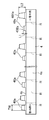
- FIG. 1 is a perspective view showing a non-aqueous electrolyte secondary battery according to the embodiment of the present disclosure.
- FIG. 2 is a cross-sectional view taken along the line II-II of FIG.
- FIG. 3 is a diagram showing a sealing plate and a group of electrode bodies including a plurality of electrode bodies.
- FIG. 4 is a schematic plan view of the electrode body as viewed from the sealing plate side.
- FIG. 5 is a schematic plan view showing the electrode body in the unfolded state.
- FIG. 6 is a cross-sectional view taken along the line VI-VI of FIG. FIG.
- FIG. 7A is a perspective view of a sealing plate to which the positive electrode terminal, the first positive electrode current collector, the negative electrode terminal, and the first negative electrode current collector are attached, as viewed from the outer surface side of the battery.
- FIG. 7B is a perspective view of a sealing plate to which the positive electrode terminal, the first positive electrode current collector, the negative electrode terminal, and the first negative electrode current collector are attached, as viewed from the inner surface side of the battery.
- FIG. 8 is a view corresponding to FIG. 6 before bending the tip region of the positive electrode tab.
- FIG. 9 is a perspective view of the electrode body before bending the tip region of the positive electrode tab.
- FIG. 10A is a diagram showing a state in which the first positive electrode current collector and the first negative electrode current collector are arranged between the second positive electrode current collector and the second negative electrode current collector.
- FIG. 10B is a diagram showing a state in which the distance between the second positive electrode current collector and the second negative electrode current collector is reduced.
- FIG. 10C is a diagram showing a state after connecting the first positive electrode current collector and the second positive electrode current collector and connecting the first negative electrode current collector and the second negative electrode current collector.
- FIG. 11 is a developed view of the electrode body holder.
- FIG. 1 is a perspective view showing a non-aqueous electrolyte secondary battery 20 according to the present disclosure.
- FIG. 2 is a cross-sectional view taken along the line II-II in FIG.
- the non-aqueous electrolyte secondary battery 20 is a battery composed of a bottomed square cylindrical outer body 1 having an opening and a sealing plate 2 for sealing the opening of the square outer body 1.
- a case 100 is provided.
- the square exterior body 1 and the sealing plate 2 are preferably made of metal, more preferably aluminum or iron, respectively.
- the square exterior body 1 has a bottom portion 1a, a pair of first side walls 1b and 1c, a second front side wall 1d, and a second rear side wall 1e.
- the pair of first side walls 1b and 1c are arranged so as to face each other in parallel.
- the second front side wall 1d and the second rear side wall 1e are arranged so as to face each other in parallel.
- the pair of first side walls 1b and 1c are perpendicular to the longitudinal direction of the sealing plate 2, and the area of the pair of first side walls 1b and 1c is smaller than the areas of the second front side wall 1d and the second rear side wall 1e.
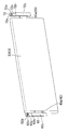
- the electrode body 3 is a flat-shaped electrode body in which a positive electrode plate 4 and a negative electrode plate 5 are wound around a separator SP.
- the winding shaft of the electrode body 3 extends perpendicular to the first side wall 1b and 1c and parallel to the second front side wall 1d and the second rear side wall 1e.
- the thickness TH of the electrode body 3 is set to 12 mm.
- two positive electrode tabs 40a as current collecting tabs are integrally projected on one end edge of the positive electrode plate 4 of the electrode body 3 in the winding axis direction. They overlap each other.
- the positive electrode tab 40a is formed in a trapezoidal plate shape in which the width gradually increases from the tip end to the base end side. These plurality of positive electrode tabs 40a are laminated to form a positive electrode tab group 40.
- the center of the curved portion of the positive electrode plate 4 is indicated by reference numeral R.
- the plurality of positive electrode tabs 40a projecting from the positive electrode plate 4 include a plurality of types of positive electrode tabs 40a having different protrusion lengths and base end widths.
- the protruding length of the positive electrode tab 40a gradually increases toward the second rear side wall 1e side (one side in the thickness direction of the electrode body 3). Therefore, the protruding length L2 of the positive electrode tab 40a that protrudes most from the second rear side wall 1e side among all the positive electrode tabs 40a is the most protruding length L2 of the second front side wall 1d side (of the electrode body 3) of all the positive electrode tabs 40a.
- the positive electrode tab 40a that protrudes most from the second rear side wall 1e side among all the positive electrode tabs 40a is designated by reference numeral 401a, and the positive electrode tab 40a that protrudes most from the second front side wall 1d side among all the positive electrode tabs 40a.
- the positive electrode tab 40a is indicated by reference numeral 402a.
- the width TW of the base end of the positive electrode tab 40a is larger as the positive electrode tab 40a has a longer protruding length.
- the protrusion length L1 of the positive electrode tab 40a having the shortest protrusion length, that is, the positive electrode tab 402a located on the second front side wall 1d side is set to 12 mm, and the positive electrode tab 401a having the longest protrusion length, that is, the most.
- the protruding length L2 of the positive electrode tab 40a located on the second rear side wall 1e side is set to 21 mm.
- the vicinity of the tips of all the positive electrode tabs 40a are connected to each other by welding with their plate surfaces facing substantially the same direction to form a connecting portion 63.
- the connecting portion 63 is formed at a position slightly separated from the tips of all the positive electrode tabs 40a, but the tip portions of all the positive electrode tabs 40a may form the connecting portion 63.
- the positive electrode plate 4 has regions in which positive electrode active material layers 4a are formed on both sides of the positive electrode core body.
- the positive electrode tab 40a is composed of an exposed portion of the positive electrode core.
- a positive electrode protective layer 4b having a lower conductivity than the positive electrode active material layer 4a is provided at the root portion of the positive electrode tab 40a.
- the positive electrode protective layer 4b may be an insulating layer made of resin, a layer containing ceramic and a resin binder, or the like. Further, the positive electrode protective layer 4b may contain a conductive material such as a carbon material. It is not necessary to provide the positive electrode protective layer 4b.
- a negative electrode tab 50a as two current collecting tabs is projected on the edge of the negative electrode plate 5 of the electrode body 3 in the winding axis direction on the other side (anti-positive electrode tab 40a side).
- These negative electrode tabs 50a have a shape that is symmetrical with respect to the positive electrode tab 40a with the cross section at the center in the winding axis direction of the electrode body 3 as the center. Therefore, the plurality of negative electrode tabs 50a projecting from the negative electrode plate 5 include a plurality of types of negative electrode tabs 50a having different protrusion lengths and base end widths. These plurality of negative electrode tabs 50a are laminated to form the negative electrode tab group 50.
- the negative electrode plate 5 has regions in which negative electrode active material layers are formed on both sides of the negative electrode core body.
- the negative electrode tab 50a is composed of an exposed negative electrode core body.
- a positive electrode terminal 8 and a negative electrode terminal 9 as electrode terminals are attached to the sealing plate 2.
- the positive electrode terminal 8 is electrically connected to the positive electrode tab group 40 via the positive electrode current collector 6.
- the positive electrode current collector 6 is composed of one first positive electrode current collector 61 and three second positive electrode current collectors 62. Each of the three second positive electrode current collectors 62 corresponds to each electrode body 3.
- the negative electrode terminal 9 is electrically connected to the negative electrode tab group 50 via the negative electrode current collector 7.
- the negative electrode current collector 7 is a first negative electrode current collector 71 having the same shape as the first positive electrode current collector 61, and three second negative electrode current collectors 72 having the same shape as the second positive electrode current collector 62. It is configured.
- Each of the three second negative electrode current collectors 72 corresponds to each electrode body 3.
- the first positive electrode current collector 61 has a substantially L-shaped cross section and is arranged between the electrode body 3 and the sealing plate 2. The first positive electrode current collector 61 is connected to the positive electrode terminal 8.
- the second positive electrode current collector 62 is arranged between the electrode body 3 and the first side wall 1b of the square exterior body 1. Specifically, the second positive electrode current collector 62 has a substantially flat plate shape parallel to the first side wall 1b, and extends toward the bottom portion 1a along the first side wall 1b. The second positive electrode current collector 62 is connected to the first positive electrode current collector 61.
- the second positive electrode current collector 62 has a current collector connecting portion 62a, an inclined portion 62b, and a tab joint portion 62c.
- the current collector connecting portion 62a is connected to the first positive electrode current collector 61.
- the positive electrode tab group 40 is connected to the tab joint portion 62c.
- the inclined portion 62b connects the current collector connection portion 62a and the tab joint portion 62c so that the current collector connection portion 62a is located inside the winding axis direction of the electrode body 3 with respect to the tab joint portion 62c. , Inclined with respect to both.
- the inclined portion 62b forms a step between the current collector connecting portion 62a and the tab joint portion 62c.
- the plate surface of the current collector connecting portion 62a and the tab joining portion 62c is directed in the winding axis direction of the electrode body 3.
- the width W1 in the thickness direction of the electrode body 3 of the tab joint portion 62c of the second positive electrode current collector 62 is set to 10 mm.
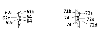
- the current collector connecting portion 62a is provided with a recess 62d.
- the portion provided with the recess 62d is thinner than the periphery thereof.
- the recess 62d is provided with a through hole 62e. In the recess 62d, the current collector connecting portion 62a is joined to the first positive electrode current collector 61.
- the second negative electrode current collector 72 also has a current collector connecting portion 72a, an inclined portion 72b, and a tab joint portion 72c, as shown in FIG.
- the current collector connecting portion 72a is provided with a recess 72d and a through hole 72e.
- the first negative electrode current collector 71 and the second negative electrode current collector 72 are left and right with respect to the first positive electrode current collector 61 and the second positive electrode current collector 62 with the cross section at the center in the winding axis direction of the electrode body 3 as the center. They are arranged so as to be symmetrical.
- the distance DI1 between the electrode body 3 and the tab joint portion 62c of the second positive electrode current collector 62 in the winding axis direction of the electrode body 3 is 1/2 of the thickness TH of the electrode body 3. It is set to 5.0 mm, which is as follows.
- the tip region including the connection portion 63 of all the positive electrode tabs 40a configured as described above has its plate surface in the plate thickness direction of the tab joint portion 62c of the second positive electrode current collector 62. It is bent toward the second rear side wall 1e side (one in the thickness direction of the electrode body 3) so as to face. That is, the tips of all the positive electrode tabs 40a constituting the connecting portion 63 face the second rear side wall 1e side. Further, the connecting portion 63 is welded to the surface of the tab joint portion 62c of the second positive electrode current collector 62 on the electrode body 3 side.
- the width W2 of the electrode body 3 of the connecting portion 63 in the thickness direction is set to 3.0 mm.
- the tips of all the positive electrode tabs 40a constituting the connection portion 63 overlap the tab joint portion 62c and the tab joint portion 62c in the plate thickness direction. That is, the tips of all the positive electrode tabs 40a do not protrude from the tab joint 62c in the plate thickness direction of the tab joint 62c. Further, among all the tips of the positive electrode tabs 40a constituting the connecting portion 63, the tip located on one side in the thickness direction of the electrode body 3 and the tip located on the other side in the thickness direction of the electrode body 3 are the electrode bodies. The deviation of 3 in the thickness direction is 2.0 mm or less. It is preferable that the positions of the tips of all the positive electrode tabs 40a in the thickness direction of the electrode bodies 3 are the same.
- the connecting portion 63 is located closer to the second front side wall 1d (the other side in the thickness direction of the electrode body 3) than the center in the thickness direction of the electrode body 3.
- the negative electrode tab group 50 is also welded to the second negative electrode current collector 72 in the same manner as the positive electrode tab group 40.
- reference numeral 10 is an external insulating member arranged between the sealing plate 2 and the positive electrode terminal 8.
- Reference numeral 11 is an internal insulating member arranged between the sealing plate 2 and the first positive electrode current collector 61.
- Reference numeral 12 is an external insulating member arranged between the sealing plate 2 and the negative electrode terminal 9.
- Reference numeral 13 is an internal insulating member arranged between the sealing plate 2 and the first negative electrode current collector 71.
- Reference numeral 14 is a box-shaped or bag-shaped insulating sheet arranged inside the square exterior body 1 and accommodating the electrode body 3.
- Reference numeral 15 is an electrolytic solution injection hole provided in the sealing plate 2.
- Reference numeral 16 is a sealing member for sealing the electrolytic solution injection hole 15.
- Reference numeral 17 is a gas discharge valve provided on the sealing plate 2.
- the sealing plate 2 has a positive electrode terminal mounting hole near one end and a negative electrode terminal mounting hole near the other end.
- the external insulating member 10 is arranged on the outer surface side around the positive electrode terminal mounting hole of the sealing plate 2, and the internal insulating member 11 and the first positive electrode current collector 61 are arranged on the inner surface side around the positive electrode terminal mounting hole of the sealing plate 2.
- the positive electrode terminal 8 is inserted into the through hole of the external insulating member 10, the positive electrode terminal mounting hole of the sealing plate 2, the through hole of the internal insulating member 11, and the through hole of the first positive electrode current collector 61 from the outside of the battery. Insert and crimp the positive electrode terminal 8 onto the first positive electrode current collector 61. Further, it is more preferable to weld the crimped portion of the positive electrode terminal 8 to the first positive electrode current collector 61.
- the external insulating member 12 is arranged on the outer surface side around the negative electrode terminal mounting hole of the sealing plate 2, and the internal insulating member 13 and the first negative electrode current collector 71 are arranged on the inner surface side around the negative electrode terminal mounting hole of the sealing plate 2.
- the negative electrode terminal 9 is inserted into the through hole of the external insulating member 12, the negative electrode terminal mounting hole of the sealing plate 2, the through hole of the internal insulating member 13, and the through hole of the first negative electrode current collector 71 from the outside of the battery. Insert and crimp the negative electrode terminal 9 onto the first negative electrode current collector 71. Further, it is more preferable to weld the crimped portion of the negative electrode terminal 9 to the first negative electrode current collector 71.
- FIG. 7A and 7B are perspective views of the sealing plate 2 to which the positive electrode terminal 8, the first positive electrode current collector 61, the negative electrode terminal 9, and the first negative electrode current collector 71 are attached.
- FIG. 7A shows the outside side of the battery
- FIG. 7B shows the inside side of the battery.
- the first positive electrode current collector 61 has a first region 61a arranged along the sealing plate 2 and a second region 61b bent from the end of the first region 61a.
- the first region 61a is arranged between the sealing plate 2 and the electrode body 3.
- the second region 61b extends from the first region 61a toward the bottom 1a of the square exterior body 1.
- the second region 61b is arranged between the first side wall 1b of the square exterior body 1 and the electrode body 3.
- the first negative electrode current collector 71 has a first region 71a arranged along the sealing plate 2 and a second region 71b bent from the end of the first region 71a.
- the first region 71a is arranged between the sealing plate 2 and the electrode body 3.
- the second region 71b extends from the first region 71a toward the bottom portion 1a of the square exterior body 1.
- the second region 71b is arranged between the first side wall 1c of the square exterior body 1 and the electrode body 3.
- the second positive electrode current collector 62 which will be described later, is connected to the second region 61b, by gripping the notch portion 61c, more stable welding can be performed, and a higher quality connecting portion can be stabilized.
- the cutout portion 61c is preferably arranged on the bottom portion 1a side of the square exterior body 1 from the internal side insulating member 11 in the second region 61b.
- the cutout portion 61c is preferably provided in the vicinity of the end portion on the first region 61a side in the second region 61b.
- the second region 71b of the first negative electrode current collector 71 is also preferably provided with notches 71c at both ends in the width direction.
- the cutout portion 61c preferably has a region not covered by the wall portion of the inner side insulating member 11.
- the positive electrode terminal 8 and the first positive electrode current collector 61 are preferably made of metal, and more preferably made of aluminum.
- the negative electrode terminal 9 and the first negative electrode current collector 71 are preferably made of metal, more preferably copper.
- the negative electrode terminal 9 can include a region made of aluminum and a region made of copper. In this case, it is preferable to connect the region made of copper to the first negative electrode current collector 71 made of copper and expose the region made of aluminum to the outside of the battery.
- Lithium nickel cobalt manganese composite oxide as a positive electrode active material, polyvinylidene fluoride (PVdF) as a binder, carbon material as a conductive material, and N-methyl-2-pyrrolidone (NMP) as a dispersion medium are lithium nickel.
- the cobalt manganese composite oxide: PVdF: carbon material is kneaded so as to have a mass ratio of 97.5: 1: 1.5 to prepare a positive electrode active material layer slurry.
- PVdF polyvinylidene fluoride
- NMP N-methyl-2-pyrrolidone
- the positive electrode active material layer slurry and the positive electrode protective layer slurry prepared by the above method are applied to both sides of the aluminum foil as the positive electrode core by a die coater. At this time, the positive electrode active material layer slurry is applied to the center of the positive electrode core in the width direction. Further, the positive electrode protective layer slurry is applied to the end portion in the width direction of the region to which the positive electrode active material layer slurry is applied.
- the positive electrode core body coated with the positive electrode active material layer slurry and the positive electrode protective layer slurry is dried to remove NMP contained in the positive electrode active material layer slurry and the positive electrode protective layer slurry. As a result, the positive electrode active material layer and the positive electrode protective layer are formed. Then, the positive electrode active material layer is compressed to obtain a positive electrode original plate.
- This positive electrode original plate is cut into a predetermined shape to obtain a positive electrode plate 4.
- the positive electrode original plate can be cut by irradiating an energy ray such as a laser, a mold, or a cutter.
- the negative electrode active material layer slurry prepared by the above method is applied to both sides of the copper foil as the negative electrode core by a die coater.
- the negative electrode core body coated with the negative electrode active material layer slurry is dried to remove the water contained in the negative electrode active material layer slurry. As a result, the negative electrode active material layer is formed. Then, the negative electrode active material layer is compressed to obtain a negative electrode original plate.
- This negative electrode original plate is cut into a predetermined shape to obtain a negative electrode plate 5.
- the negative electrode original plate can be cut by irradiating an energy ray such as a laser, a mold, or a cutter.
- the strip-shaped positive electrode plate 4 and the strip-shaped negative electrode plate 5 produced by the above method are wound via a polyolefin strip-shaped separator SP to prepare a flat wound-shaped electrode body 3.
- the electrode body 3 has a flat region in the center, and curved portions at both ends of the flat region.
- a positive electrode tab group 40 in which a plurality of positive electrode tabs 40a are laminated is provided at one end of the electrode body 3 in the direction in which the winding axis extends.
- a negative electrode tab group 50 in which a plurality of negative electrode tabs 50a are laminated is provided at the other end of the electrode body 3 in the direction in which the winding shaft extends.
- the center of the positive electrode tab group 40 and the center of the negative electrode tab group 50 are located in a direction perpendicular to the direction in which the winding axis of the electrode body 3 extends and in a direction perpendicular to the thickness direction of the electrode body 3. It is arranged so as to be offset from the winding axis to one side.
- the positive electrode tab 40a and / or the negative electrode tab 50a By making the shape of the positive electrode tab 40a and / or the negative electrode tab 50a in a plan view gradually increasing from the tip to the root, an impact or vibration is applied to the non-aqueous electrolyte secondary battery 20. Even in this case, the positive electrode tab 40a and / or the negative electrode tab 50a can be made less likely to be damaged. Further, it is more effective to make the corner portion of the root portion R-shaped.
- the tip regions of all the positive electrode tabs 40a are connected to the tab joint 62c of the second positive electrode current collector 62.
- the second positive electrode current collector 62 is formed by applying the welding jig T to a position slightly lower than the tips of all the positive electrode tabs 40a to perform welding. Weld to.
- a portion slightly lower than the tips of all the positive electrode tabs 40a constitutes the connecting portion 63.
- the connecting portions 63 may be formed at the tips of all the positive electrode tabs 40a.
- the tab joint portion 62c of the second positive electrode current collector 62 has its plate surface oriented in the thickness direction of the electrode body 3. Further, the tip regions of all the positive electrode tabs 40a are oriented so that the plate surface faces the thickness direction of the electrode body 3 and is closer to the positive electrode tab 40a side (one end side in the thickness direction of the electrode body 3) having the shortest protruding length. It is piled up in a state of being piled up. At this time, the distance DI2 between the electrode body 3 and the tab joint portion 62c of the second positive electrode current collector 62 is set to 6 mm, and all the positive electrode tabs 40a are bent.
- the connection portion 63 is connected to the root side (in FIG. 8) of the positive electrode tab group 40 in the width direction of the tab joint portion 62c (left-right direction in FIG. 8). It is preferable to arrange them closer to the left side). With such a configuration, when the positive electrode tab group 40 is bent, a curved shape can be more reliably formed in the vicinity of the root of the positive electrode tab group 40. As a result, damage to the positive electrode tab group 40 can be suppressed. Further, even if the positive electrode tab 40a is misaligned, the positive electrode tab group 40 and the tab joint portion 62c can be stably joined.
- the lower end portion of the second positive electrode current collector 62 (the portion serving as the end portion on the bottom portion 1a side of the square exterior body 1) is the lower end portion of the positive electrode tab group 40 (the end portion on the bottom portion 1a side of the square exterior body 1). It is preferable that it is located below the portion). With such a configuration, in the step of bending the positive electrode tab group 40, which will be described later, the positive electrode tab group 40 can be bent more reliably and stably.
- the tip regions of all the positive electrode tabs 40a are oriented so that the plate surface thereof is in the substantially winding axis direction of the electrode body 3 (for example, the tab joint portion 62c with respect to the winding axis). Bend to a state where the inclination of is less than ⁇ 15 °). As a result, the tab joint portion 62c of the second positive electrode current collector 62 is in a state in which the plate surface thereof is oriented in the substantially winding axis direction of the electrode body 3. In this way, the positive electrode tab group 40 can be bent without bending the second positive electrode current collector 62.
- the negative electrode tab 50a is also attached to the second negative electrode current collector 72 in the same manner as the positive electrode tab 40a.
- Electrode body group As shown in FIG. 3, a plurality of electrode bodies 3 in which the positive electrode tab group 40 and the negative electrode tab group 50 are each bent are laminated and fixed by electrode body fixing means such as tape. Each positive electrode tab group 40 is arranged on the same side, and each negative electrode tab group 50 is arranged on the same side. Further, in each electrode body 3, the positive electrode tab group 40 is bent in the same direction. In each electrode body 3, the negative electrode tab group 50 is bent in the same direction.
- the second positive electrode current collectors 62 attached to the electrode bodies 3 are arranged at intervals and connected to the second region 61b of the first positive electrode current collector 61. The same applies to each second negative electrode current collector 72.
- the second region 61b of the first positive electrode current collector 61 is arranged inside the current collector connection portion 62a of the second positive positive collector 62, and the second region 71b of the first negative negative current collector 71 is the second negative negative collector. It is arranged inside the current collector connecting portion 72a of the electric body 72. Then, the second region 61b of the first positive electrode current collector 61 and the current collector connecting portion 62a of the second positive electrode current collector 62 are joined. Further, the second region 71b of the first negative electrode current collector 71 is joined to the current collector connecting portion 72a of the second negative electrode current collector 72.
- ultrasonic welding ultrasonic bonding
- resistance welding welding by irradiation with high energy rays such as a laser, or the like
- welding by irradiating a high energy ray such as a laser.
- 10A to 10C show the second region 61b of the first positive electrode current collector 61, the second region 71b of the first negative electrode current collector 71, and the current collector connection portion 62a of the second positive electrode current collector 62 at each stage. , And a cross-sectional view of the current collector connection portion 72a of the second negative electrode current collector 72 along the winding axis of the electrode body 3.
- the second of the first positive electrode current collector 61 is between the current collector connection portion 62a of the second positive electrode current collector 62 and the current collector connection portion 72a of the second negative electrode current collector 72.
- the region 61b and the second region 71b of the first negative electrode current collector 71 are arranged.
- the distance D1 between the inner surface of the current collector connecting portion 62a and the inner surface of the current collector connecting portion 72a is preferably larger than the distance D2 between the outer surface of the second region 61b and the outer surface of the second region 71b.
- D1 is preferably 0.1 to 5 mm larger than D2, and more preferably 0.2 to 3 mm larger.
- the current collector connection portion 62a and / or the current collector connection portion 72a is displaced inward so that the distance between the current collector connection portion 62a and the current collector connection portion 72a becomes small.
- the distance D1 between the inner surface of the current collector connecting portion 62a and the inner surface of the current collector connecting portion 72a is changed to D1'.
- the difference between D2 and D1' is preferably 0 to 0.2 mm.
- a joint portion 64 which is a welded portion between the second region 61b and the current collector connecting portion 62a, is formed in the recess 62d.
- a joint portion 74 which is a welded portion between the second region 71b and the current collector connecting portion 72a, is formed in the recess 72d.
- the first positive electrode current collector 61 and the second positive electrode current collector 62, and the first negative electrode current collector 71 and the second negative electrode current collector 72 can be performed by a simpler method. , Can be welded more stably. Therefore, the highly reliable joint portion 64 and the joint portion 74 can be formed.
- the portion where the recesses 62d and 72d are formed is a portion thinner than the periphery thereof.
- a higher quality joint portion can be formed more stably. Therefore, it becomes a more reliable secondary battery.
- the through hole 62e to measure the presence or absence of a gap between the second region 61b and the current collector connecting portion 62a or the size of the gap, the second region 61b and the current collector connecting portion can be more stably measured.
- 62a can be joined by welding. The same applies to the through hole 72e.
- FIG. 3 is a perspective view showing a state after connecting the first positive electrode current collector 61 and the second positive electrode current collector 62, and the first negative electrode current collector 71 and the second negative electrode current collector 72, respectively.
- FIG. 11 is a developed view of the electrode body holder 14.
- the insulating sheet constituting the electrode body holder 14 is bent at the portion indicated by the broken line to form a box-shaped electrode body holder 14.
- the electrode body holder 14 includes a holder bottom 14a, a holder first main surface 14b, a holder second main surface 14c, a holder first side surface 14d, a holder second side surface 14e, a holder third side surface 14f, a holder fourth side surface 14g, and a holder first. It has 5 side surfaces 14h and a holder 6th side surface 14i.
- the electrode body holder 14 When the electrode body holder 14 has a box shape, it has a region where the holder first side surface 14d, the holder second side surface 14e, and the holder third side surface 14f overlap, and the holder fourth side surface 14g, the holder fifth side surface 14h, and the holder The sixth side surface 14i has an overlapping region.
- the present embodiment since two positive electrode tabs 40a are provided on each circumference of the positive electrode plate 4, compared to the case where only one positive electrode tab 40a is provided on each circumference of the positive electrode plate 4, the inside of the positive electrode plate 4 is provided.
- the variation in the distance from each portion to the positive electrode tab 40a can be reduced, and the potential difference in the positive electrode plate 4 can be reduced. Therefore, deterioration of the positive electrode plate 4 can be suppressed, and the durability of the non-aqueous electrolyte secondary battery 20 can be enhanced.
- the current collecting resistance of the positive electrode plate 4 can be reduced, so that the output current of the non-aqueous electrolyte secondary battery 20 can be increased.
- the negative electrode tabs 50a are provided from each portion in the negative electrode plate 5 as compared with the case where only one negative electrode tab 50a is provided on each circumference of the negative electrode plate 5.
- the variation in the distance to the negative electrode plate 5 can be reduced, and the potential difference in the negative electrode plate 5 can be reduced. Therefore, deterioration of the negative electrode plate 5 can be suppressed, and the durability of the non-aqueous electrolyte secondary battery 20 can be enhanced.
- the current collecting resistance of the negative electrode plate 5 can be reduced, so that the output current of the non-aqueous electrolyte secondary battery 20 can be increased.
- the tips of all the positive electrode tabs 40a constituting the connection portion 63 are overlapped with the tab joint portion 62c in the plate thickness direction of the tab joint portion 62c, the tips of the positive electrode tabs 40a protrude from the tab joint portion 62c and are adjacent to each other. It is possible to prevent the electrode body 3 from coming into contact with the electrode body 3. Further, since it is not necessary to provide a restricting member such as a tape in order to restrict the portion of the positive electrode tab 40a protruding from the tab joint portion 62c from coming into contact with the adjacent electrode body 3, compared to the case where the restricting member is provided. It is possible to reduce the number of parts and eliminate the trouble of assembling the regulatory member.
- the tip located on one side in the thickness direction of the electrode body 3 and the tip located on the other side in the thickness direction of the electrode body 3 are the electrode bodies. Since the deviation of 3 in the thickness direction is 2.0 mm or less, the welding operation of welding the positive electrode tab 40a to the second positive electrode current collector 62 becomes easier than in the case where the deviation exceeds 2.0 mm. Similarly, the welding operation of welding the negative electrode tab 50a to the second negative electrode current collector 72 becomes easy.
- the protruding length L2 of the positive electrode tab 40a protruding most from the second rear side wall 1e side is set to the protruding length L2 of all the positive electrode tabs 40a constituting the connecting portion 63. Since the protrusion length L1 of the positive electrode tab 40a protruding from the second front side wall 1d side is longer than the protrusion length L1, even if the connecting portion 63 is arranged closer to the second front side wall 1d than the center in the thickness direction of the electrode body 3.
- the deviation in the thickness direction of the electrode body 3 between the tip of the positive electrode tab 40a protruding from the second rear side wall 1e side and the tip of the positive electrode tab 40a protruding from the second front side wall 1d side can be reduced.
- the same effect can be obtained for the negative electrode tab 50a.
- the connecting portion 63 is made of the electrode body 3 rather than the center in the thickness direction of the electrode body 3. Even if it is arranged closer to the second front side wall 1d, the deviation in the thickness direction of the electrode bodies 3 at the tips of all the positive electrode tabs 40a can be reduced. The same effect can be obtained for the negative electrode tab 50a.
- the width TW of the base end of the positive electrode tab 40a constituting the connecting portion 63 is increased by the length of the positive electrode tab 40a having a longer protrusion length, the width TW of the base end of the positive electrode tab 40a is made equal to each other.
- the resistance of the positive electrode tab 40a having a long protrusion length is not increased, and the current flowing through the positive electrode tab 40a can be made uniform regardless of the protrusion length. The same effect can be obtained for the negative electrode tab 50a.
- the positive electrode current collector 6 includes the first positive electrode current collector 61 and the second positive electrode current collector 62, the positive electrode current collector 6 is not bent when the positive electrode tab group 40 is bent. , The positive electrode tab group 40 can be bent, and a secondary battery having a higher volume energy density can be obtained more stably by a simpler method. Even when the number of electrode bodies 3 housed in the battery case 100 is larger than two, a highly reliable secondary battery can be stably manufactured without making the positive electrode current collector 6 a complicated shape. .. Therefore, the degree of freedom regarding the number of electrode bodies 3 housed in the battery case 100 is improved.
- the tab joint portion 62c of the second positive electrode current collector 62 is arranged on the first side wall 1b side of the square exterior body 1 with respect to the current collector connection portion 62a of the second positive electrode current collector 62.
- the positive electrode tab group 40 is preferably closer to the sealing plate 2. As a result, the conductive path from the positive electrode tab group 40 to the positive electrode terminal 8 can be shortened, and the non-aqueous electrolyte secondary battery 20 having a small internal resistance is obtained.
- the negative electrode tab group 50 is preferably closer to the sealing plate 2. As a result, the conductive path from the negative electrode tab group 50 to the negative electrode terminal 9 can be shortened, and the non-aqueous electrolyte secondary battery 20 having a small internal resistance is obtained.
- the electrode body holder 14 It is preferable to arrange another insulating member. Further, an electrode body holder is located between the region where the second region 71b of the first negative electrode current collector 71 and the current collector connecting portion 72a of the second negative electrode current collector 72 overlap and the first side wall 1c of the square exterior body 1. It is preferable to arrange an insulating member different from 14. With such a configuration, even when an impact or vibration is applied to the non-aqueous electrolyte secondary battery 20, it is possible to prevent damage to the joint between the members, the positive electrode tab group 40, or the negative electrode tab group 50.
- the present invention is applied to the non-aqueous electrolyte secondary battery 20 having three electrode bodies 3, but the present invention is not provided with a plurality of or only one electrode body 3. It can also be applied to the water electrolyte secondary battery 20.
- two positive electrode tabs 40a are provided for each circumference at one end edge of the positive electrode plate 4 of the electrode body 3 in the winding axis direction, but at least two positive electrode tabs 40a are provided for each circumference. It may be provided, and three or more positive electrode tabs 40a may be provided for each circumference.
- at least two negative electrode tabs 50a may be provided on the other edge of the negative electrode plate 5 in the winding axis direction (on the anti-positive electrode tab 40a side) for each circumference, and three or more negative electrodes may be provided for each circumference.
- a tab 50a may be provided.
- the plurality of positive electrode tabs 40a projecting from the positive electrode plate 4 include a plurality of types of positive electrode tabs 40a having different protrusion lengths and base end widths, but the positive electrode plate 4 includes.
- the plurality of positive electrode tabs 40a provided may include a plurality of types of positive electrode tabs 40a in which only one of the protruding length and the width of the proximal end is different from each other.
- the width of the base end of all the positive electrode tabs 40a may be the same.
- the plurality of negative electrode tabs 50a projecting from the negative electrode plate 5 may include a plurality of types of negative electrode tabs 50a in which only one of the protruding length and the width of the proximal end is different from each other.
- Non-aqueous electrolyte secondary battery 40a Positive electrode tab (collection tab) 50a Negative electrode tab (current collector tab) 61 1st positive electrode current collector 61a 1st region 61b 2nd region 62 2nd positive electrode current collector 62c Tab joint 63 Connection part 71 1st negative electrode current collector 71a 1st region 71b 2nd region 72 2nd negative electrode current collector Body 72c Tab joint SP Separator L1, L2 Projection length DI1 Interval TH Thickness TW Width
Landscapes
- Chemical & Material Sciences (AREA)
- Chemical Kinetics & Catalysis (AREA)
- Electrochemistry (AREA)
- General Chemical & Material Sciences (AREA)
- Engineering & Computer Science (AREA)
- Manufacturing & Machinery (AREA)
- Connection Of Batteries Or Terminals (AREA)
Abstract
電極体の正極板の巻回軸方向一方の端縁に、各周毎に2つの正極タブを突設する。電極体の負極板の巻回軸方向他方の端縁に、各周毎に2つの負極タブを突設する。正極板に突設された複数の正極タブに、突出長さ、及び基端の幅が互いに異なる複数種類の正極タブを含め、負極板に突設された複数の負極タブに、突出長さ、及び基端の幅が互いに異なる複数種類の負極タブを含める。
Description
本開示は、帯状の正極板と帯状の負極板とが帯状のセパレータを介して巻回された電極体を備えた二次電池に関する。
特許文献1には、帯状の正極板と帯状の負極板とが帯状のセパレータを介して巻回された電極体を備えた二次電池が開示されている。この二次電池では、電極体の正極板の巻回軸方向一方の端縁及び負極板の巻回軸方向他方の端縁に、各周毎に1つの集電タブが突設されている。
特許文献1では、集電タブが、正極板及び負極板の各周に1つだけしか設けられておらず、電極板内の各部位から集電タブまでの距離のバラつきが大きいので、電極板内の電位差が大きくなり、電極板の劣化が進行しやすい。したがって、二次電池の耐久性が低くなる。
また、二次電池の出力電流を大きくしたいという要望もある。
本開示に係る二次電池は、帯状の正極板と帯状の負極板とが帯状のセパレータを介して巻回された電極体を備えた二次電池であって、前記電極体の正極板の巻回軸方向一方の端縁、及び前記負極板の巻回軸方向他方の端縁には、各周毎に、少なくとも2つの集電タブが突設されており、前記正極板に突設された複数の前記集電タブは、突出長さ、及び基端の幅の少なくとも一方が互いに異なる複数種類の集電タブを含み、
前記負極板に突設された複数の前記集電タブは、突出長さ、及び基端の幅の少なくとも一方が互いに異なる複数種類の集電タブを含むことを特徴とする。
前記負極板に突設された複数の前記集電タブは、突出長さ、及び基端の幅の少なくとも一方が互いに異なる複数種類の集電タブを含むことを特徴とする。
本開示によれば、二次電池の耐久性を高めるとともに、二次電池の出力電流を大きくできる。
以下、本開示の実施形態を図面に基づいて詳細に説明する。以下の好ましい実施形態の説明は、本質的に例示に過ぎず、本開示、その適用物あるいはその用途を制限することを意図するものでは全くない。
図1は、本開示に係る非水電解質二次電池20を示す斜視図である。図2は、図1におけるII-II線断面図である。図1及び図2に示すように、非水電解質二次電池20は、開口を有する有底角筒状の角形外装体1と、角形外装体1の開口を封口する封口板2とからなる電池ケース100を備える。角形外装体1及び封口板2は、それぞれ金属製であることが好ましく、アルミニウム製又は鉄製であることがより好ましい。
角形外装体1は、底部1aと、一対の第1側壁1b,1cと、第2前側壁1d及び第2後側壁1eとを有する。一対の第1側壁1b,1cは、互いに平行に対向する向きに配置されている。第2前側壁1d及び第2後側壁1eは、互いに平行に対向する向きに配置されている。一対の第1側壁1b,1cは、封口板2の長手方向に垂直であり、一対の第1側壁1b,1cの面積は、第2前側壁1d及び第2後側壁1eの面積よりも小さい。
角形外装体1内には、図3に示すように、正極板4と負極板5とを含む3つの電極体3が電解質と共に収容されている。電極体3は、図4に示すように、正極板4と負極板5とがセパレータSPを介して巻回された扁平形状の電極体である。電極体3の巻回軸は、第1側壁1b,1cに対して垂直、且つ、第2前側壁1d及び第2後側壁1eに対して平行に延びる。電極体3の厚さTHは、12mmに設定されている。
電極体3の正極板4の巻回軸方向一方の端縁には、図4~図6に示すように、各周毎に2つの集電タブとしての正極タブ40aが一体に突設されて互いに重なっている。正極タブ40aは、先端から基端側に向かって徐々に幅が大きくなる台形板状に形成されている。これら複数の正極タブ40aが、積層されて正極タブ群40を構成している。なお、図5中、正極板4が湾曲するアール部の中心を符号Rで示す。
正極板4に突設された複数の正極タブ40aは、突出長さ、及び基端の幅が互いに異なる複数種類の正極タブ40aを含む。詳しくは、正極タブ40aの突出長さは、第2後側壁1e側(電極体3の厚さ方向一方側)に向かって徐々に長くなっている。したがって、全ての正極タブ40aのうち、最も第2後側壁1e側から突出する正極タブ40aの突出長さL2は、全ての正極タブ40aのうち、最も第2前側壁1d側(電極体3の厚さ方向他方側)から突出する正極タブ40aの突出長さL1よりも長くなっている。図4及び図5中、全ての正極タブ40aのうち、最も第2後側壁1e側から突出する正極タブ40aを符号401a、全ての正極タブ40aのうち、最も第2前側壁1d側から突出する正極タブ40aを符号402aで示す。また、正極タブ40aの基端の幅TWは、突出長さが長い正極タブ40a程、大きくなっている。なお、最も突出長さの短い正極タブ40a、すなわち最も第2前側壁1d側に位置する正極タブ402aの突出長さL1は、12mmに設定され、最も突出長さの長い正極タブ401a、すなわち最も第2後側壁1e側に位置する正極タブ40aの突出長さL2は、21mmに設定されている。
全ての正極タブ40aの先端近傍は、その板面を略等しい方向に向けて互いに溶接により接続されて接続部63を構成している。なお、本実施形態では、全ての正極タブ40aの先端から若干離れた箇所が接続部63を構成したが、全ての正極タブ40aの先端部が、接続部63を構成してもよい。
正極板4は正極芯体の両面に正極活物質層4aが形成された領域を有する。正極タブ40aは正極芯体露出部からなる。正極タブ40aの根本部分には正極活物質層4aよりも導電性が低い正極保護層4bが設けられている。正極保護層4bとしては、樹脂製の絶縁層、セラミック及び樹脂バインダーを含む層等とすることができる。また、正極保護層4bが炭素材等の導電材を含んでいてもよい。なお、正極保護層4bを設けなくてもよい。
電極体3の負極板5の巻回軸方向他方(反正極タブ40a側)の端縁には、各周毎に2つの集電タブとしての負極タブ50aが突設されている。これら負極タブ50aは、電極体3の巻回軸方向中央の断面を中心として正極タブ40aに対して左右対称となる形状を有している。したがって、負極板5に突設された複数の負極タブ50aは、突出長さ、及び基端の幅が互いに異なる複数種類の負極タブ50aを含む。これら複数の負極タブ50aが、積層されて負極タブ群50を構成している。
負極板5は負極芯体の両面に負極活物質層が形成された領域を有する。負極タブ50aは負極芯体露出部からなる。
封口板2には、電極端子としての正極端子8及び負極端子9が取り付けられている。正極端子8は、正極集電体6を介して正極タブ群40に電気的に接続されている。正極集電体6は、1つの第1正極集電体61及び3つの第2正極集電体62で構成されている。3つの第2正極集電体62は、それぞれ各電極体3に対応している。負極端子9は、負極集電体7を介して負極タブ群50に電気的に接続されている。負極集電体7は、第1正極集電体61と等しい形状の1つの第1負極集電体71、及び第2正極集電体62と等しい形状の3つの第2負極集電体72で構成されている。3つの第2負極集電体72は、それぞれ各電極体3に対応している。
第1正極集電体61は、断面略L字状であり、電極体3と封口板2との間に配置されている。第1正極集電体61は、正極端子8に接続されている。
第2正極集電体62は、電極体3と角形外装体1における第1側壁1bとの間に配置されている。具体的には、第2正極集電体62は、第1側壁1bに平行な略平板状をなし、第1側壁1bに沿って底部1a側へ延びている。第2正極集電体62は、第1正極集電体61に接続されている。
第2正極集電体62は、図3に示すように、集電体接続部62aと、傾斜部62bと、タブ接合部62cとを有する。集電体接続部62aは、第1正極集電体61に接続される。タブ接合部62cには、正極タブ群40が接続される。傾斜部62bは、集電体接続部62aとタブ接合部62cとを、集電体接続部62aがタブ接合部62cよりも電極体3の巻回軸方向内側に位置するように連結しており、両者に対して傾斜している。傾斜部62bにより集電体接続部62aとタブ接合部62cの間に段差が形成される。集電体接続部62a及びタブ接合部62cは、その板面を電極体3の巻回軸方向に向けている。図6に示すように、第2正極集電体62のタブ接合部62cの電極体3の厚さ方向の幅W1は、10mmに設定されている。
集電体接続部62aには、凹部62dが設けられている。凹部62dが設けられている部分は、その周囲よりも厚みが薄い。凹部62dには、貫通孔62eが設けられている。凹部62dにおいて、集電体接続部62aが第1正極集電体61に接合される。
第2負極集電体72も、第2正極集電体62と同様に、図9に示すように、集電体接続部72aと、傾斜部72bと、タブ接合部72cとを有する。集電体接続部72aには、凹部72d及び貫通孔72eが設けられている。
第1負極集電体71及び第2負極集電体72は、電極体3の巻回軸方向中央の断面を中心として第1正極集電体61及び第2正極集電体62に対して左右対称となるように配置されている。
図6に示すように、電極体3と第2正極集電体62のタブ接合部62cとの前記電極体3の巻回軸方向の間隔DI1は、電極体3の厚さTHの1/2以下である5.0mmに設定されている。
図6に示すように、上述のように構成された全ての正極タブ40aの接続部63を含む先端領域は、その板面を第2正極集電体62のタブ接合部62cの板厚方向に向けるように第2後側壁1e側(電極体3の厚さ方向一方)に折り曲げられている。つまり、接続部63を構成する全ての正極タブ40aの先端は、第2後側壁1e側に向いている。また、接続部63が、第2正極集電体62のタブ接合部62cの電極体3側の面に溶接されている。接続部63の電極体3の厚さ方向の幅W2は、3.0mmに設定されている。
接続部63を構成する全ての正極タブ40aの先端は、タブ接合部62cと当該タブ接合部62cの板厚方向に重なっている。つまり、全ての正極タブ40aの先端は、タブ接合部62cから当該タブ接合部62cの板厚方向にはみ出ていない。また、接続部63を構成する全ての正極タブ40aの先端のうち、最も電極体3の厚さ方向一方に位置する先端と、最も電極体3の厚さ方向他方に位置する先端との電極体3の厚さ方向のずれが、2.0mm以下となっている。なお、全ての正極タブ40aの先端の電極体3の厚さ方向の位置は、一致していることが好ましい。
また、接続部63は電極体3の厚さ方向中央よりも第2前側壁1d(電極体3の厚さ方向他方)寄りに位置している。
負極タブ群50も正極タブ群40と同様に第2負極集電体72に溶接されている。
なお、図2において、符号10は、封口板2と正極端子8との間に配置された外部側絶縁部材である。符号11は、封口板2と第1正極集電体61との間に配置された内部側絶縁部材である。符号12は、封口板2と負極端子9との間に配置された外部側絶縁部材である。符号13は、封口板2と第1負極集電体71との間に配置された内部側絶縁部材である。符号14は、角形外装体1の内部に配置され、電極体3を収容する箱状ないし袋状の絶縁シートである。符号15は、封口板2に設けられた電解液注液孔である。符号16は、電解液注液孔15を封止する封止部材である。符号17は、封口板2に設けられたガス排出弁である。
次に非水電解質二次電池20の製造方法及び各構成の詳細を説明する。
[封口板への端子及び第1集電体の取り付け]
封口板2は、一方の端部近傍に正極端子取り付け孔を有し、他方の端部近傍に負極端子取り付け孔を有する。封口板2の正極端子取り付け孔の周囲の外面側に外部側絶縁部材10を配置し、封口板2の正極端子取り付け孔の周囲の内面側に内部側絶縁部材11及び第1正極集電体61を配置する。そして、電池外部側から正極端子8を、外部側絶縁部材10の貫通孔、封口板2の正極端子取り付け孔、内部側絶縁部材11の貫通孔、及び第1正極集電体61の貫通孔に挿入し、正極端子8を第1正極集電体61上にカシメる。更に、正極端子8においてカシメられた部分を、第1正極集電体61に溶接することがより好ましい。
封口板2は、一方の端部近傍に正極端子取り付け孔を有し、他方の端部近傍に負極端子取り付け孔を有する。封口板2の正極端子取り付け孔の周囲の外面側に外部側絶縁部材10を配置し、封口板2の正極端子取り付け孔の周囲の内面側に内部側絶縁部材11及び第1正極集電体61を配置する。そして、電池外部側から正極端子8を、外部側絶縁部材10の貫通孔、封口板2の正極端子取り付け孔、内部側絶縁部材11の貫通孔、及び第1正極集電体61の貫通孔に挿入し、正極端子8を第1正極集電体61上にカシメる。更に、正極端子8においてカシメられた部分を、第1正極集電体61に溶接することがより好ましい。
封口板2の負極端子取り付け孔の周囲の外面側に外部側絶縁部材12を配置し、封口板2の負極端子取り付け孔の周囲の内面側に内部側絶縁部材13及び第1負極集電体71を配置する。そして、電池外部側から負極端子9を、外部側絶縁部材12の貫通孔、封口板2の負極端子取り付け孔、内部側絶縁部材13の貫通孔、及び第1負極集電体71の貫通孔に挿入し、負極端子9を第1負極集電体71上にカシメる。更に、負極端子9においてカシメられた部分を、第1負極集電体71に溶接することがより好ましい。
図7Aと図7Bは、正極端子8、第1正極集電体61、負極端子9及び第1負極集電体71が取り付けられた封口板2の斜視図である。図7Aは電池外部側を示し、図7Bは電池内部側を示す。
第1正極集電体61は封口板2に沿って配置される第1領域61aと、第1領域61aの端部から折り曲げられた第2領域61bを有する。非水電解質二次電池20の状態において、第1領域61aは封口板2と電極体3の間に配置される。第2領域61bは、第1領域61aから角形外装体1の底部1aに向かって延びる。第2領域61bは、角形外装体1の第1側壁1bと電極体3の間に配置される。
第1負極集電体71は封口板2に沿って配置される第1領域71aと、第1領域71aの端部から折り曲げられた第2領域71bを有する。非水電解質二次電池20の状態において、第1領域71aは封口板2と電極体3の間に配置される。第2領域71bは、第1領域71aから角形外装体1の底部1aに向かって延びる。第2領域71bは、角形外装体1の第1側壁1cと電極体3の間に配置される。
第1正極集電体61の第2領域61bにおいて、幅方向の両端部に切り欠き部61cを設けることが好ましい。第2領域61bに後述する第2正極集電体62を接続する際に、切り欠き部61cを把持することで、より安定的に溶接を行うことが可能となり、より質の高い接続部を安定的に形成できる。切り欠き部61cは、第2領域61bにおいて前記内部側絶縁部材11より角形外装体1の底部1a側に配置されることが好ましい。切り欠き部61cは、第2領域61bにおいて第1領域61a側の端部近傍に設けられることが好ましい。なお、第1負極集電体71の第2領域71bについても幅方向の両端部に切り欠き部71cを設けることが好ましい。内部側絶縁部材11が第2領域61bの一部を覆う壁部を有する場合、切り欠き部61cは内部側絶縁部材11の壁部によって覆われていない領域を有することが好ましい。
正極端子8及び第1正極集電体61は金属製であることが好ましく、アルミニウム製であることがより好ましい。負極端子9及び第1負極集電体71は金属製であることが好ましく、銅製であることがより好ましい。なお、負極端子9が、アルミニウムからなる領域と銅からなる領域を含むようにすることができる。この場合、銅からなる領域を銅製の第1負極集電体71に接続し、アルミニウムからなる領域を電池外部側に露出させることが好ましい。
[正極板]
まず、正極板の製造方法を説明する。
まず、正極板の製造方法を説明する。
[正極活物質層スラリーの作製]
正極活物質としてのリチウムニッケルコバルトマンガン複合酸化物、結着材としてのポリフッ化ビニリデン(PVdF)、導電材としての炭素材料、及び分散媒としてのN-メチル-2-ピロリドン(NMP)をリチウムニッケルコバルトマンガン複合酸化物:PVdF:炭素材料の質量比が97.5:1:1.5となるように混練し、正極活物質層スラリーを作製する。
正極活物質としてのリチウムニッケルコバルトマンガン複合酸化物、結着材としてのポリフッ化ビニリデン(PVdF)、導電材としての炭素材料、及び分散媒としてのN-メチル-2-ピロリドン(NMP)をリチウムニッケルコバルトマンガン複合酸化物:PVdF:炭素材料の質量比が97.5:1:1.5となるように混練し、正極活物質層スラリーを作製する。
[正極保護層スラリーの作製]
アルミナ粉末、導電材としての炭素材料、結着材としてのポリフッ化ビニリデン(PVdF)と分散媒としてのN-メチル-2-ピロリドン(NMP)を、アルミナ粉末:炭素材料:PVdFの質量比が83:3:14となるように混練し、保護層スラリーを作製する。
アルミナ粉末、導電材としての炭素材料、結着材としてのポリフッ化ビニリデン(PVdF)と分散媒としてのN-メチル-2-ピロリドン(NMP)を、アルミナ粉末:炭素材料:PVdFの質量比が83:3:14となるように混練し、保護層スラリーを作製する。
[正極活物質層及び正極保護層の形成]
正極芯体としてアルミニウム箔の両面に、上述の方法で作製した正極活物質層スラリー及び正極保護層スラリーをダイコータにより塗布する。このとき、正極芯体の幅方向の中央に正極活物質層スラリーが塗布される。また、正極活物質層スラリーが塗布される領域の幅方向の端部に正極保護層スラリーが塗布される。
正極芯体としてアルミニウム箔の両面に、上述の方法で作製した正極活物質層スラリー及び正極保護層スラリーをダイコータにより塗布する。このとき、正極芯体の幅方向の中央に正極活物質層スラリーが塗布される。また、正極活物質層スラリーが塗布される領域の幅方向の端部に正極保護層スラリーが塗布される。
正極活物質層スラリー及び正極保護層スラリーが塗布された正極芯体を乾燥させ、正極活物質層スラリー及び正極保護層スラリーに含まれるNMPを除去する。これにより正極活物質層及び正極保護層が形成される。その後、正極活物質層を圧縮して正極原板とする。この正極原板を所定形状に切断し、正極板4とする。なお正極原板の切断は、レーザー等のエネルギー線の照射、金型、あるいはカッター等により行うことができる。
[負極板]
次に、負極板の製造方法を説明する。
次に、負極板の製造方法を説明する。
[負極活物質層スラリーの作製]
負極活物質としての黒鉛、結着材としてのスチレンブタジエンゴム(SBR)及びカルボキシメチルセルロース(CMC)、及び分散媒としての水を、黒鉛:SBR:CMCの質量比が98:1:1となるように混練し、負極活物質層スラリーを作製する。
負極活物質としての黒鉛、結着材としてのスチレンブタジエンゴム(SBR)及びカルボキシメチルセルロース(CMC)、及び分散媒としての水を、黒鉛:SBR:CMCの質量比が98:1:1となるように混練し、負極活物質層スラリーを作製する。
[負極活物質層の形成]
負極芯体としての銅箔の両面に、上述の方法で作製した負極活物質層スラリーをダイコータにより塗布する。
負極芯体としての銅箔の両面に、上述の方法で作製した負極活物質層スラリーをダイコータにより塗布する。
負極活物質層スラリーが塗布された負極芯体を乾燥させ、負極活物質層スラリーに含まれる水を除去する。これにより負極活物質層が形成される。その後、負極活物質層を圧縮して負極原板とする。この負極原板を所定形状に切断し、負極板5とする。なお負極原板の切断は、レーザー等のエネルギー線の照射、金型、あるいはカッター等により行うことができる。
[電極体の作製]
上述の方法で作製した帯状の正極板4及び帯状の負極板5を、ポリオレフィン製の帯状のセパレータSPを介して巻回し、扁平状の巻回型の電極体3を作製する。電極体3は中央に扁平状の領域を有し、扁平状の領域の両端に湾曲部を有する。
上述の方法で作製した帯状の正極板4及び帯状の負極板5を、ポリオレフィン製の帯状のセパレータSPを介して巻回し、扁平状の巻回型の電極体3を作製する。電極体3は中央に扁平状の領域を有し、扁平状の領域の両端に湾曲部を有する。
電極体3の巻回軸が延びる方向における一方の端部には複数の正極タブ40aが積層された正極タブ群40が設けられている。電極体3の巻回軸が延びる方向における他方の端部には複数の負極タブ50aが積層された負極タブ群50が設けられている。なお、電極体3の巻回軸が延びる方向に対して垂直な方向で、且つ電極体3の厚み方向に対して垂直な方向において、正極タブ群40の中心及び負極タブ群50の中心は、巻回軸から一方にずれて配置されている。
なお、正極タブ40a及び/又は負極タブ50aの平面視の形状を、先端から根本に向かって徐々に幅が大きくなる形状とすることで、非水電解質二次電池20に衝撃や振動が加わった場合でも、正極タブ40a及び/又は負極タブ50aを損傷し難くできる。また、根本部分のコーナー部をR形状とすることがより効果的である。
なお、上述のように正極タブ40aの根本部分に正極保護層4bを設けることにより、正極タブ40aの損傷を抑制できる。また、負極タブ50aの根本部分に負極活物質層を設けることにより、負極タブ50aの損傷を抑制できる。
[第1集電体とタブ群の接続]
上述のように構成された非水電解質二次電池20を製造するには、図8に示すように、すべての正極タブ40aの先端領域を、第2正極集電体62のタブ接合部62cに重ねた状態で、すべての正極タブ40aの先端よりも若干下がった位置に溶接治具Tを当てて溶接を行うことにより、すべての正極タブ40aを互いに接合するとともに、第2正極集電体62に溶接する。これにより、すべての正極タブ40aの先端よりも若干下がった部分が、接続部63を構成する。なお、すべての正極タブ40aの先端部に溶接治具Tを当てて溶接を行うことにより、すべての正極タブ40aの先端部で接続部63が構成されるようにしてもよい。このとき、図9にも示すように、第2正極集電体62のタブ接合部62cは、その板面を電極体3の厚さ方向に向けている。また、すべての正極タブ40aの先端領域は、その板面を電極体3の厚さ方向に向け、かつ最も突出長さの短い正極タブ40a側(電極体3の厚さ方向一端側)に寄せた状態で重ねられている。また、このとき、電極体3と第2正極集電体62のタブ接合部62cとの間隔DI2は、6mmに設定され、全ての正極タブ40aが撓んでいる。
上述のように構成された非水電解質二次電池20を製造するには、図8に示すように、すべての正極タブ40aの先端領域を、第2正極集電体62のタブ接合部62cに重ねた状態で、すべての正極タブ40aの先端よりも若干下がった位置に溶接治具Tを当てて溶接を行うことにより、すべての正極タブ40aを互いに接合するとともに、第2正極集電体62に溶接する。これにより、すべての正極タブ40aの先端よりも若干下がった部分が、接続部63を構成する。なお、すべての正極タブ40aの先端部に溶接治具Tを当てて溶接を行うことにより、すべての正極タブ40aの先端部で接続部63が構成されるようにしてもよい。このとき、図9にも示すように、第2正極集電体62のタブ接合部62cは、その板面を電極体3の厚さ方向に向けている。また、すべての正極タブ40aの先端領域は、その板面を電極体3の厚さ方向に向け、かつ最も突出長さの短い正極タブ40a側(電極体3の厚さ方向一端側)に寄せた状態で重ねられている。また、このとき、電極体3と第2正極集電体62のタブ接合部62cとの間隔DI2は、6mmに設定され、全ての正極タブ40aが撓んでいる。
このとき、第2正極集電体62のタブ接合部62cにおいて、接続部63は、タブ接合部62cの幅方向(図8では左右方向)において、正極タブ群40の根本側(図8においては左側)に寄せて配置されることが好ましい。このような構成であると、正極タブ群40を折り曲げた際、より確実に正極タブ群40の根本近傍に安定的に湾曲形状を形成することができる。これにより、正極タブ群40の損傷を抑制できる。また、正極タブ40aに位置ずれが生じていても、安定的に正極タブ群40とタブ接合部62cを接合できる。
また、第2正極集電体62の下端部(角形外装体1の底部1a側の端部となる部分)は、正極タブ群40の下端部(角形外装体1の底部1a側の端部となる部分)よりも下方に位置することが好ましい。このような構成であると、後述する正極タブ群40を折り曲げる工程において、正極タブ群40をより確実に安定的に折り曲げることが可能となる。
この状態から、図6に示すように、すべての正極タブ40aの先端領域を、その板面を前記電極体3の略巻回軸方向に向けた状態(例えば、巻回軸に対するタブ接合部62cの傾きが±15°より小さい状態)に折り曲げる。これにより、第2正極集電体62のタブ接合部62cが、その板面を電極体3の略巻回軸方向に向けた状態となる。このように、第2正極集電体62を折り曲げることなく、正極タブ群40を折り曲げることができる。
負極タブ50aも、正極タブ40aと同様の方法で、第2負極集電体72に取り付ける。
[電極体群]
図3に示すように、正極タブ群40及び負極タブ群50がそれぞれ折り曲げられた状態の複数の電極体3を積層し、テープ等の電極体固定手段で固定する。各正極タブ群40は同じ側に配置され、各負極タブ群50は同じ側に配置される。また、各電極体3において、正極タブ群40はそれぞれ同じ方向に折り曲げられている。各電極体3において、負極タブ群50はそれぞれ同じ方向に折り曲げられている。
図3に示すように、正極タブ群40及び負極タブ群50がそれぞれ折り曲げられた状態の複数の電極体3を積層し、テープ等の電極体固定手段で固定する。各正極タブ群40は同じ側に配置され、各負極タブ群50は同じ側に配置される。また、各電極体3において、正極タブ群40はそれぞれ同じ方向に折り曲げられている。各電極体3において、負極タブ群50はそれぞれ同じ方向に折り曲げられている。
電極体3の積層方向において、各電極体3に取り付けられた第2正極集電体62は間隔を置いて並べられて第1正極集電体61の第2領域61b上に接続されている。各第2負極集電体72についても同様である。
[第1集電体と第2集電体の接続]
第1正極集電体61の第2領域61bを第2正極集電体62の集電体接続部62aの内側に配置し、第1負極集電体71の第2領域71bを第2負極集電体72の集電体接続部72aの内側に配置する。そして、第1正極集電体61の第2領域61bと第2正極集電体62の集電体接続部62aを接合する。また、第1負極集電体71の第2領域71bを第2負極集電体72の集電体接続部72aに接合する。接合方法としては、超音波溶接(超音波接合)、抵抗溶接、レーザー等の高エネルギー線の照射による溶接等を用いることができる。特にレーザー等の高エネルギー線の照射による溶接を用いることが好ましい。
第1正極集電体61の第2領域61bを第2正極集電体62の集電体接続部62aの内側に配置し、第1負極集電体71の第2領域71bを第2負極集電体72の集電体接続部72aの内側に配置する。そして、第1正極集電体61の第2領域61bと第2正極集電体62の集電体接続部62aを接合する。また、第1負極集電体71の第2領域71bを第2負極集電体72の集電体接続部72aに接合する。接合方法としては、超音波溶接(超音波接合)、抵抗溶接、レーザー等の高エネルギー線の照射による溶接等を用いることができる。特にレーザー等の高エネルギー線の照射による溶接を用いることが好ましい。
図10Aから図10Cは、各段階における第1正極集電体61の第2領域61b、第1負極集電体71の第2領域71b、第2正極集電体62の集電体接続部62a、及び第2負極集電体72の集電体接続部72aの電極体3の巻回軸に沿った断面図である。
図10Aに示すように、第2正極集電体62の集電体接続部62aと第2負極集電体72の集電体接続部72aの間に、第1正極集電体61の第2領域61bと第1負極集電体71の第2領域71bを配置する。このとき、集電体接続部62aの内面と集電体接続部72aの内面の距離D1は、第2領域61bの外面と第2領域71bの外面の距離D2よりも大きいことが好ましい。なお、D1はD2よりも、0.1~5mm大きいことが好ましく、0.2~3mm大きいことがより好ましい。
次に、図10Bに示すように、集電体接続部62aと集電体接続部72aの距離が小さくなるように、集電体接続部62a及び/又は集電体接続部72aを内側に変位させる。これにより、集電体接続部62aの内面と集電体接続部72aの内面の距離D1をD1´に変化させる。このとき、D2とD1´の差は0~0.2mmであることが好ましい。
図10Bに示す状態で、レーザー等の高エネルギー線を集電体接続部62a、集電体接続部72aのそれぞれに照射する。これにより、第1正極集電体61の第2領域61bと第2正極集電体62の集電体接続部62aが溶接により接合され、第1負極集電体71の第2領域71bと第2負極集電体72の集電体接続部72aが溶接により接合される。
図10Cに示すように、第2領域61bと集電体接続部62aの溶接部である接合部64が、凹部62d内に形成される。また、第2領域71bと集電体接続部72aの溶接部である接合部74が、凹部72d内に形成される。
図10Aから図10Cの手順とすることにより、より簡単な方法で、第1正極集電体61と第2正極集電体62、及び第1負極集電体71と第2負極集電体72、をより安定的に溶接することができる。よって、信頼性の高い接合部64及び接合部74を形成できる。
凹部62d,72dが形成されている部分は、その周囲よりも厚みが薄い部分である。この厚みの薄い部分に接合部64,74が形成されるように溶接を行うことにより、より質の高い接合部をより安定的に形成することができる。よって、より信頼性の高い二次電池となる。また、貫通孔62eを利用して、第2領域61bと集電体接続部62aの隙間の有無ないし隙間の大きさを測定することにより、より安定的に第2領域61bと集電体接続部62aを溶接により接合することができる。なお、貫通孔72eについても同様である。
図3は、第1正極集電体61と第2正極集電体62、第1負極集電体71と第2負極集電体72を、それぞれ接続した後の状態を示す斜視図である。
[電極体ホルダー]
図11は、電極体ホルダー14の展開図である。図11において破線の部分で電極体ホルダー14を構成する絶縁シートを折り曲げることにより箱状の電極体ホルダー14とする。電極体ホルダー14は、ホルダー底部14a、ホルダー第1主面14b、ホルダー第2主面14c、ホルダー第1側面14d、ホルダー第2側面14e、ホルダー第3側面14f、ホルダー第4側面14g、ホルダー第5側面14h、ホルダー第6側面14iを有する。
図11は、電極体ホルダー14の展開図である。図11において破線の部分で電極体ホルダー14を構成する絶縁シートを折り曲げることにより箱状の電極体ホルダー14とする。電極体ホルダー14は、ホルダー底部14a、ホルダー第1主面14b、ホルダー第2主面14c、ホルダー第1側面14d、ホルダー第2側面14e、ホルダー第3側面14f、ホルダー第4側面14g、ホルダー第5側面14h、ホルダー第6側面14iを有する。
電極体ホルダー14を箱状としたとき、ホルダー第1側面14d、ホルダー第2側面14e、及びホルダー第3側面14fが重なる領域を有し、ホルダー第4側面14g、ホルダー第5側面14h、及びホルダー第6側面14iが重なる領域を有する。
箱状の電極体ホルダー14内に3つの電極体3が配置された状態で、これら3つの電極体3を角形外装体1内に挿入する。そして、封口板2を角形外装体1に接合し、角形外装体1の開口を封口板2により封口する。封口板2に設けられた電解液注液孔15から電解液を注液し、封止部材16で電解液注液孔15を封止する。これにより非水電解質二次電池20とする。
したがって、本実施形態によれば、正極タブ40aを正極板4の各周に2つ設けたので、正極タブ40aを正極板4の各周に1つだけ設ける場合に比べ、正極板4内の各部位から正極タブ40aまでの距離のバラつきを小さくし、正極板4内の電位差を低減できる。したがって、正極板4の劣化を抑制し、非水電解質二次電池20の耐久性を高められる。
また、正極タブ40aを正極板4の各周に1つだけ設ける場合に比べ、正極板4の集電抵抗を小さくできるので、非水電解質二次電池20の出力電流を大きくできる。
同様に、負極タブ50aを負極板5の各周に2つ設けたので、負極タブ50aを負極板5の各周に1つだけ設ける場合に比べ、負極板5内の各部位から負極タブ50aまでの距離のバラつきを小さくし、負極板5内の電位差を低減できる。したがって、負極板5の劣化を抑制し、非水電解質二次電池20の耐久性を高められる。
また、負極タブ50aを負極板5の各周に1つだけ設ける場合に比べ、負極板5の集電抵抗を小さくできるので、非水電解質二次電池20の出力電流を大きくできる。
また、接続部63を構成する全ての正極タブ40aの先端を、タブ接合部62cと当該タブ接合部62cの板厚方向に重ねたので、正極タブ40aの先端がタブ接合部62cからはみ出て隣接する電極体3に接触するのを防止できる。また、正極タブ40aのタブ接合部62cからはみ出た部分が隣接する電極体3に接触するのを規制するためにテープ等の規制部材を設けなくてよいので、当該規制部材を設ける場合に比べ、部品点数を削減するとともに当該規制部材を組み付ける手間をなくすことができる。
また、接続部63を構成する全ての正極タブ40aの先端のうち、最も電極体3の厚さ方向一方に位置する先端と、最も電極体3の厚さ方向他方に位置する先端との電極体3の厚さ方向のずれを、2.0mm以下とするので、当該ずれが2.0mmを超える場合に比べ、正極タブ40aを第2正極集電体62に溶接する溶接作業が容易になる。同様に、負極タブ50aを第2負極集電体72に溶接する溶接作業も容易になる。
また、接続部63を構成する全ての正極タブ40aのうち、最も第2後側壁1e側から突出する正極タブ40aの突出長さL2を、接続部63を構成する全ての正極タブ40aのうち、最も第2前側壁1d側から突出する正極タブ40aの突出長さL1よりも長くするので、接続部63を電極体3の厚さ方向中央よりも第2前側壁1d寄りに配置しても、最も第2後側壁1e側から突出する正極タブ40aの先端と、最も第2前側壁1d側から突出する正極タブ40aの先端との電極体3の厚さ方向のずれを小さくできる。負極タブ50aについても同様の効果が得られる。
また、接続部63を構成する正極タブ40aの突出長さを、第2後側壁1e側に向かって徐々に長くするので、接続部63を電極体3の厚さ方向中央よりも電極体3の第2前側壁1d寄りに配置しても、すべての正極タブ40aの先端の電極体3の厚さ方向のずれを小さくできる。負極タブ50aについても同様の効果が得られる。
また、接続部63を構成する正極タブ40aの基端の幅TWを、突出長さが長い正極タブ40a程、大きくしたので、正極タブ40aの基端の幅TWを互いに等しくした場合に比べ、突出長さが長い正極タブ40aの抵抗を増加させず、突出長さによらず正極タブ40aに流れる電流を均一化できる。負極タブ50aについても同様の効果が得られる。
また、正極集電体6が第1正極集電体61と第2正極集電体62とを含む構成となっているので、正極タブ群40を折り曲げる際、正極集電体6を折り曲げることなく、正極タブ群40を折り曲げることができ、より簡単な方法で、より安定的に体積エネルギー密度が高い二次電池とすることができる。電池ケース100に収容される電極体3の数が2個より多い場合でも、正極集電体6を複雑な形状とすることなく、信頼性の高い二次電池を安定的に製造できるようになる。したがって、電池ケース100に収容される電極体3の個数についての自由度が向上する。
また、第2正極集電体62のタブ接合部62cが第2正極集電体62の集電体接続部62aよりも角形外装体1の第1側壁1b側に配置される。このような構成であると、第1側壁1bと電極体3の間のスペースをより有効に活用できるため、電極体3の発電部をより大きくでき、より体積エネルギー密度の高い二次電池となる。なお、第2負極集電体72についても同様である。
電極体3において正極タブ群40は封口板2側に寄っていることが好ましい。これにより、正極タブ群40から正極端子8までの導電経路を短くすることができ内部抵抗の小さい非水電解質二次電池20となる。電極体3において負極タブ群50は封口板2側に寄っていることが好ましい。これにより、負極タブ群50から負極端子9までの導電経路を短くすることができ内部抵抗の小さい非水電解質二次電池20となる。
第1正極集電体61の第2領域61bと第2正極集電体62の集電体接続部62aが重なる領域と、角形外装体1の第1側壁1bの間に、電極体ホルダー14とは別の絶縁部材を配置することが好ましい。また、第1負極集電体71の第2領域71bと第2負極集電体72の集電体接続部72aが重なる領域と、角形外装体1の第1側壁1cの間に、電極体ホルダー14とは別の絶縁部材を配置することが好ましい。このような構成により、非水電解質二次電池20に衝撃や振動が加わった場合でも、各部材間の接合部、正極タブ群40、ないし負極タブ群50が損傷することを抑制できる。
(その他の実施形態)
上述の実施形態は本願発明の例示であって、本願発明はこれらの例に限定されず、これらの例に周知技術や慣用技術、公知技術を組み合わせたり、一部置き換えたりしてもよい。また当業者であれば容易に思いつく改変発明も本願発明に含まれる。
上述の実施形態は本願発明の例示であって、本願発明はこれらの例に限定されず、これらの例に周知技術や慣用技術、公知技術を組み合わせたり、一部置き換えたりしてもよい。また当業者であれば容易に思いつく改変発明も本願発明に含まれる。
上述の実施形態では、電極体3を3つ備えた非水電解質二次電池20に本発明を適用したが、本発明は、電極体3を3つ以外の複数、又は1つだけ備えた非水電解質二次電池20にも適用できる。
また、上述の実施形態では、電極体3の正極板4の巻回軸方向一方の端縁に各周毎に2つの正極タブ40aを設けたが、各周毎に少なくとも2つの正極タブ40aを設ければよく、各周毎に3つ以上の正極タブ40aを設けてもよい。同様に、負極板5の巻回軸方向他方(反正極タブ40a側)の端縁にも、各周毎に少なくとも2つの負極タブ50aを設ければよく、各周毎に3つ以上の負極タブ50aを設けてもよい。
また、上述の実施形態では、正極板4に突設された複数の正極タブ40aに、突出長さ、及び基端の幅が互いに異なる複数種類の正極タブ40aを含めたが、正極板4に突設された複数の正極タブ40aに、突出長さ、及び基端の幅のいずれか一方だけが互いに異なる複数種類の正極タブ40aを含めてもよい。例えば、すべての正極タブ40aの基端の幅を共通としてもよい。同様に、負極板5に突設された複数の負極タブ50aに、突出長さ、及び基端の幅のいずれか一方だけが互いに異なる複数種類の負極タブ50aを含めてもよい。
1 角形外装体
1b,1c 第1側壁
2 封口板
3 電極体
4 正極板
5 負極板
8 正極端子
9 負極端子
20 非水電解質二次電池
40a 正極タブ(集電タブ)
50a 負極タブ(集電タブ)
61 第1正極集電体
61a 第1領域
61b 第2領域
62 第2正極集電体
62c タブ接合部
63 接続部
71 第1負極集電体
71a 第1領域
71b 第2領域
72 第2負極集電体
72c タブ接合部
SP セパレータ
L1,L2 突出長さ
DI1 間隔
TH 厚さ
TW 幅
1b,1c 第1側壁
2 封口板
3 電極体
4 正極板
5 負極板
8 正極端子
9 負極端子
20 非水電解質二次電池
40a 正極タブ(集電タブ)
50a 負極タブ(集電タブ)
61 第1正極集電体
61a 第1領域
61b 第2領域
62 第2正極集電体
62c タブ接合部
63 接続部
71 第1負極集電体
71a 第1領域
71b 第2領域
72 第2負極集電体
72c タブ接合部
SP セパレータ
L1,L2 突出長さ
DI1 間隔
TH 厚さ
TW 幅
Claims (7)
- 帯状の正極板と帯状の負極板とが帯状のセパレータを介して巻回された電極体を備えた二次電池であって、
前記電極体の正極板の巻回軸方向一方の端縁、及び前記負極板の巻回軸方向他方の端縁には、各周毎に、少なくとも2つの集電タブが突設されており、
前記正極板に突設された複数の前記集電タブは、突出長さ、及び基端の幅の少なくとも一方が互いに異なる複数種類の集電タブを含み、
前記負極板に突設された複数の前記集電タブは、突出長さ、及び基端の幅の少なくとも一方が互いに異なる複数種類の集電タブを含むことを特徴とする二次電池。 - 請求項1に記載の二次電池において、
開口、及び互いに対向するように配置された一対の側壁を有する外装体と、
前記開口を封口する封口板と、
前記封口板に取り付けられた端子とをさらに備え、
前記電極体は、扁平形状をなし、その巻回軸方向を前記側壁に対して垂直に向けた状態で前記外装体に収容され、
前記集電タブと前記端子とは、第1集電体及び第2集電体により電気的に接続され、
前記第1集電体は、前記封口板と前記電極体との間に配置された第1領域と、前記第1領域の端部から折れ曲がり一方の前記側壁と前記電極体との間に配置された第2領域とを含み、
前記第2集電体は、その板面を前記電極体の巻回軸方向に向けた板状のタブ接合部を有し、
複数の前記集電タブの先端部又は先端近傍は、その板面を略等しい方向に向けて互いに接合され、かつ前記第2集電体のタブ接合部の電極体側の面に溶接された接続部を構成し、
複数の前記集電タブの前記接続部を含む先端領域は、その板面を前記第2集電体のタブ接合部の板厚方向に向けるように前記電極体の厚さ方向一方に折り曲げられ、
前記接続部を構成する全ての集電タブの先端は、前記タブ接合部と当該タブ接合部の板厚方向に重なり、
前記第2集電体は、前記第1集電体の第2領域に溶接されていることを特徴とする二次電池。 - 請求項2に記載の二次電池において、
前記接続部を構成する全ての集電タブの先端のうち、最も前記電極体の厚さ方向一方に位置する先端と、最も前記電極体の厚さ方向他方に位置する先端との前記電極体の厚さ方向のずれが、2.0mm以下であることを特徴とする二次電池。 - 請求項2又は3に記載の二次電池において、
前記接続部を構成する全ての集電タブのうち、最も前記電極体の厚さ方向一方側から突出する集電タブの突出長さは、前記接続部を構成する全ての集電タブのうち、最も前記電極体の厚さ方向他方側から突出する集電タブの突出長さよりも長く、
前記接続部は、前記電極体の厚さ方向中央よりも前記電極体の前記厚さ方向他方寄りに位置していることを特徴とする二次電池。 - 請求項4に記載の二次電池において、
前記接続部を構成する集電タブの突出長さは、前記電極体の前記厚さ方向一方側に向かって徐々に長くなっていることを特徴とする二次電池。 - 請求項4又は5に記載の二次電池において、
前記接続部を構成する集電タブの基端の幅は、突出長さが長い集電タブ程、大きいことを特徴とする二次電池。 - 請求項4~6のいずれか1項に記載の二次電池において、
前記電極体と前記第2集電体のタブ接合部との前記巻回軸方向の間隔は、前記電極体の厚さの1/2以下に設定されていることを特徴とする二次電池。
Priority Applications (4)
| Application Number | Priority Date | Filing Date | Title |
|---|---|---|---|
| US17/914,169 US20230238564A1 (en) | 2020-03-26 | 2021-02-08 | Secondary battery |
| JP2022509362A JPWO2021192664A1 (ja) | 2020-03-26 | 2021-02-08 | |
| EP21775169.2A EP4131529A4 (en) | 2020-03-26 | 2021-02-08 | SECONDARY BATTERY |
| CN202180021068.6A CN115280589B (zh) | 2020-03-26 | 2021-02-08 | 二次电池 |
Applications Claiming Priority (2)
| Application Number | Priority Date | Filing Date | Title |
|---|---|---|---|
| JP2020055371 | 2020-03-26 | ||
| JP2020-055371 | 2020-03-26 |
Publications (1)
| Publication Number | Publication Date |
|---|---|
| WO2021192664A1 true WO2021192664A1 (ja) | 2021-09-30 |
Family
ID=77891345
Family Applications (1)
| Application Number | Title | Priority Date | Filing Date |
|---|---|---|---|
| PCT/JP2021/004624 WO2021192664A1 (ja) | 2020-03-26 | 2021-02-08 | 二次電池 |
Country Status (5)
| Country | Link |
|---|---|
| US (1) | US20230238564A1 (ja) |
| EP (1) | EP4131529A4 (ja) |
| JP (1) | JPWO2021192664A1 (ja) |
| CN (1) | CN115280589B (ja) |
| WO (1) | WO2021192664A1 (ja) |
Cited By (3)
| Publication number | Priority date | Publication date | Assignee | Title |
|---|---|---|---|---|
| EP4187664A1 (en) * | 2021-11-26 | 2023-05-31 | Prime Planet Energy & Solutions, Inc. | Battery |
| JP2023078785A (ja) * | 2021-11-26 | 2023-06-07 | プライムプラネットエナジー&ソリューションズ株式会社 | 電池 |
| WO2023123274A1 (zh) * | 2021-12-30 | 2023-07-06 | 宁德时代新能源科技股份有限公司 | 极片、电极组件、电池、用电装置及极片的制作方法 |
Citations (8)
| Publication number | Priority date | Publication date | Assignee | Title |
|---|---|---|---|---|
| WO2013001821A1 (ja) * | 2011-06-28 | 2013-01-03 | 日本ケミコン株式会社 | 蓄電デバイスおよび蓄電デバイスの製造方法 |
| JP2014060045A (ja) * | 2012-09-18 | 2014-04-03 | Mitsubishi Motors Corp | 二次電池の電極構造 |
| JP2015141847A (ja) * | 2014-01-29 | 2015-08-03 | 株式会社東芝 | 二次電池、及び二次電池の製造方法 |
| JP2016139596A (ja) | 2015-01-28 | 2016-08-04 | 三星エスディアイ株式会社Samsung SDI Co., Ltd. | 電極タブを有する電極アセンブリおよび二次電池 |
| JP2017050069A (ja) * | 2015-08-31 | 2017-03-09 | 株式会社豊田自動織機 | 蓄電装置 |
| JP2019061779A (ja) * | 2017-09-25 | 2019-04-18 | パナソニック株式会社 | 蓄電装置及び蓄電装置の製造方法 |
| JP2019212434A (ja) * | 2018-06-01 | 2019-12-12 | 株式会社豊田自動織機 | 電極製造装置 |
| JP2021028896A (ja) * | 2019-08-09 | 2021-02-25 | 株式会社豊田自動織機 | 蓄電装置の製造方法 |
Family Cites Families (4)
| Publication number | Priority date | Publication date | Assignee | Title |
|---|---|---|---|---|
| JP5830953B2 (ja) * | 2010-11-17 | 2015-12-09 | ソニー株式会社 | 二次電池、バッテリユニットおよびバッテリモジュール |
| JP6582489B2 (ja) * | 2015-03-30 | 2019-10-02 | 三洋電機株式会社 | 角形二次電池及びそれを用いた組電池 |
| JP6550848B2 (ja) * | 2015-03-30 | 2019-07-31 | 三洋電機株式会社 | 角形二次電池 |
| JP6962167B2 (ja) * | 2017-12-12 | 2021-11-05 | 三洋電機株式会社 | 二次電池 |
-
2021
- 2021-02-08 CN CN202180021068.6A patent/CN115280589B/zh active Active
- 2021-02-08 JP JP2022509362A patent/JPWO2021192664A1/ja active Pending
- 2021-02-08 EP EP21775169.2A patent/EP4131529A4/en active Pending
- 2021-02-08 WO PCT/JP2021/004624 patent/WO2021192664A1/ja unknown
- 2021-02-08 US US17/914,169 patent/US20230238564A1/en active Pending
Patent Citations (8)
| Publication number | Priority date | Publication date | Assignee | Title |
|---|---|---|---|---|
| WO2013001821A1 (ja) * | 2011-06-28 | 2013-01-03 | 日本ケミコン株式会社 | 蓄電デバイスおよび蓄電デバイスの製造方法 |
| JP2014060045A (ja) * | 2012-09-18 | 2014-04-03 | Mitsubishi Motors Corp | 二次電池の電極構造 |
| JP2015141847A (ja) * | 2014-01-29 | 2015-08-03 | 株式会社東芝 | 二次電池、及び二次電池の製造方法 |
| JP2016139596A (ja) | 2015-01-28 | 2016-08-04 | 三星エスディアイ株式会社Samsung SDI Co., Ltd. | 電極タブを有する電極アセンブリおよび二次電池 |
| JP2017050069A (ja) * | 2015-08-31 | 2017-03-09 | 株式会社豊田自動織機 | 蓄電装置 |
| JP2019061779A (ja) * | 2017-09-25 | 2019-04-18 | パナソニック株式会社 | 蓄電装置及び蓄電装置の製造方法 |
| JP2019212434A (ja) * | 2018-06-01 | 2019-12-12 | 株式会社豊田自動織機 | 電極製造装置 |
| JP2021028896A (ja) * | 2019-08-09 | 2021-02-25 | 株式会社豊田自動織機 | 蓄電装置の製造方法 |
Non-Patent Citations (1)
| Title |
|---|
| See also references of EP4131529A4 |
Cited By (6)
| Publication number | Priority date | Publication date | Assignee | Title |
|---|---|---|---|---|
| EP4187664A1 (en) * | 2021-11-26 | 2023-05-31 | Prime Planet Energy & Solutions, Inc. | Battery |
| JP2023078786A (ja) * | 2021-11-26 | 2023-06-07 | プライムプラネットエナジー&ソリューションズ株式会社 | 電池 |
| JP2023078785A (ja) * | 2021-11-26 | 2023-06-07 | プライムプラネットエナジー&ソリューションズ株式会社 | 電池 |
| JP7495915B2 (ja) | 2021-11-26 | 2024-06-05 | プライムプラネットエナジー&ソリューションズ株式会社 | 電池 |
| JP7495916B2 (ja) | 2021-11-26 | 2024-06-05 | プライムプラネットエナジー&ソリューションズ株式会社 | 電池 |
| WO2023123274A1 (zh) * | 2021-12-30 | 2023-07-06 | 宁德时代新能源科技股份有限公司 | 极片、电极组件、电池、用电装置及极片的制作方法 |
Also Published As
| Publication number | Publication date |
|---|---|
| EP4131529A1 (en) | 2023-02-08 |
| CN115280589A (zh) | 2022-11-01 |
| CN115280589B (zh) | 2024-06-14 |
| JPWO2021192664A1 (ja) | 2021-09-30 |
| EP4131529A4 (en) | 2024-06-05 |
| US20230238564A1 (en) | 2023-07-27 |
Similar Documents
| Publication | Publication Date | Title |
|---|---|---|
| WO2021060010A1 (ja) | 二次電池及びその製造方法 | |
| WO2021192664A1 (ja) | 二次電池 | |
| JP5214543B2 (ja) | 二次電池 | |
| JP7115464B2 (ja) | 角形二次電池及びその製造方法 | |
| WO2021060009A1 (ja) | 二次電池及びその製造方法 | |
| JP6522418B2 (ja) | 角形二次電池及びそれを用いた組電池、並びにその製造方法 | |
| US11050092B2 (en) | Method for manufacturing prismatic secondary battery | |
| JP7006613B2 (ja) | 角形二次電池 | |
| WO2018155522A1 (ja) | 角形二次電池 | |
| JP6729137B2 (ja) | 二次電池及びその製造方法、並びにそれを用いた組電池 | |
| JP7500678B2 (ja) | 角形二次電池 | |
| JP2019087478A (ja) | 二次電池 | |
| JP6935798B2 (ja) | 二次電池の製造方法 | |
| JP7330211B2 (ja) | 角形二次電池 | |
| WO2021192665A1 (ja) | 二次電池 | |
| CN108232280B (zh) | 方形二次电池及其制造方法 | |
| JP6641842B2 (ja) | 角形二次電池 | |
| CN108232310B (zh) | 方形二次电池及其制造方法 | |
| JP7329538B2 (ja) | 二次電池及びその製造方法 | |
| JP2004273288A (ja) | 筒型二次電池 | |
| JP7442269B2 (ja) | 二次電池 | |
| JP6777202B2 (ja) | 角形二次電池の製造方法 | |
| WO2021060007A1 (ja) | 二次電池 |
Legal Events
| Date | Code | Title | Description |
|---|---|---|---|
| 121 | Ep: the epo has been informed by wipo that ep was designated in this application |
Ref document number: 21775169 Country of ref document: EP Kind code of ref document: A1 |
|
| ENP | Entry into the national phase |
Ref document number: 2022509362 Country of ref document: JP Kind code of ref document: A |
|
| NENP | Non-entry into the national phase |
Ref country code: DE |
|
| ENP | Entry into the national phase |
Ref document number: 2021775169 Country of ref document: EP Effective date: 20221026 |