WO2021192238A1 - スクロール圧縮機 - Google Patents
スクロール圧縮機 Download PDFInfo
- Publication number
- WO2021192238A1 WO2021192238A1 PCT/JP2020/014084 JP2020014084W WO2021192238A1 WO 2021192238 A1 WO2021192238 A1 WO 2021192238A1 JP 2020014084 W JP2020014084 W JP 2020014084W WO 2021192238 A1 WO2021192238 A1 WO 2021192238A1
- Authority
- WO
- WIPO (PCT)
- Prior art keywords
- valve
- scroll
- communication hole
- fixed scroll
- discharge
- Prior art date
- Legal status (The legal status is an assumption and is not a legal conclusion. Google has not performed a legal analysis and makes no representation as to the accuracy of the status listed.)
- Ceased
Links
Images






Classifications
-
- F—MECHANICAL ENGINEERING; LIGHTING; HEATING; WEAPONS; BLASTING
- F04—POSITIVE - DISPLACEMENT MACHINES FOR LIQUIDS; PUMPS FOR LIQUIDS OR ELASTIC FLUIDS
- F04C—ROTARY-PISTON, OR OSCILLATING-PISTON, POSITIVE-DISPLACEMENT MACHINES FOR LIQUIDS; ROTARY-PISTON, OR OSCILLATING-PISTON, POSITIVE-DISPLACEMENT PUMPS
- F04C18/00—Rotary-piston pumps specially adapted for elastic fluids
- F04C18/02—Rotary-piston pumps specially adapted for elastic fluids of arcuate-engagement type, i.e. with circular translatory movement of co-operating members, each member having the same number of teeth or tooth-equivalents
-
- F—MECHANICAL ENGINEERING; LIGHTING; HEATING; WEAPONS; BLASTING
- F04—POSITIVE - DISPLACEMENT MACHINES FOR LIQUIDS; PUMPS FOR LIQUIDS OR ELASTIC FLUIDS
- F04C—ROTARY-PISTON, OR OSCILLATING-PISTON, POSITIVE-DISPLACEMENT MACHINES FOR LIQUIDS; ROTARY-PISTON, OR OSCILLATING-PISTON, POSITIVE-DISPLACEMENT PUMPS
- F04C29/00—Component parts, details or accessories of pumps or pumping installations, not provided for in groups F04C18/00 - F04C28/00
- F04C29/12—Arrangements for admission or discharge of the working fluid, e.g. constructional features of the inlet or outlet
Definitions
- the present disclosure relates to a scroll compressor that employs a bypass mechanism that releases pressure when a high-low pressure reversal occurs.
- the scroll compressor compresses the refrigerant sucked from the suction pipe in a compression chamber formed in the compression mechanism and discharges it.
- the pressure in the space on the side that sucks in the refrigerant is lower than that in the space on the side that discharges the refrigerant.
- the frame may shift.
- a ball valve provided in a communication hole that communicates a high-pressure space in which a high-pressure refrigerant gas compressed by a compression mechanism is discharged and a low-pressure space in an suction pressure atmosphere, and a ball valve.
- the scroll compressor is provided with a bypass mechanism composed of a chamber that suppresses the movement of the gas into a high-pressure space.
- the prior art of Patent Document 1 describes a bypass mechanism using a valve.
- the bypass mechanism using a ball valve it is necessary to arrange the chamber so as to cover the communication hole in order to prevent the steel ball from jumping out into the high pressure space. Further, in the bypass mechanism using a valve, the ability to release the pressure when the high and low pressure reversal occurs depends on the diameter of the hole, but when the diameter of the hole is increased, the valve body also becomes large. Therefore, for example, when the injection mechanism is provided on the base plate of the fixed scroll, the valve may not be provided in contact with the injection mechanism.
- This disclosure is made in order to solve the above-mentioned problems, and a scroll capable of providing a bypass mechanism regardless of the specifications of the compressor and sufficiently releasing the pressure at the time of high and low pressure reversal.
- the purpose is to provide a compressor.
- the scroll compressor according to the present disclosure is sucked by a main frame provided in a shell and a compression chamber supported by the main frame and formed by spiral teeth of a fixed scroll and spiral teeth of a swing scroll.
- a compression mechanism unit that compresses and discharges the generated refrigerant, first and second communication holes provided in the fixed scroll and communicating the space on the suction side and the space on the discharge side, and the discharge of the fixed scroll.
- the first and second valves provided on the side and opening the first and second communication holes when the pressure on the suction side becomes larger than the pressure on the discharge side, and the first valve.
- the distance between the first fixing member that fixes the valve to the fixed scroll and the first fixing member that fixes the second valve to the fixed scroll is the first and second communication holes.
- a second fixing member which is longer than the distance between them, is provided.
- the bypass mechanism is composed of a plurality of communication holes, valves and fixing members, and the distance between the first and second fixing members of the fixed scroll is the distance between the first and second communication holes. Even if the fixed scroll space is limited by the discharge valve, etc., while ensuring the area of the hole that allows the refrigerant to escape sufficiently during high and low pressure reversal, there are multiple discharge valves, etc. It can be placed without interfering with the valve.
- FIG. 2 is a diagram when the valve is in the open state. It is the figure which looked at the fixed scroll from the discharge side. It is the figure which removed the bypass mechanism in the fixed scroll of FIG. It is the figure which looked at the fixed scroll from the suction side. It is a figure for demonstrating the scroll compressor which concerns on Embodiment 2 of this invention.
- FIG. 7 is a view of the fixed scroll of FIG. 7 as viewed from the suction side. It is a figure for demonstrating the scroll compressor which concerns on Embodiment 3 of this invention.
- 9 is a diagram in which a valve is provided in FIG. It is a figure for demonstrating the scroll compressor which concerns on Embodiment 4 of this invention.
- FIG. 1 is a diagram for explaining the scroll compressor according to the first embodiment of the present invention.
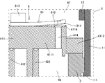
- FIG. 2 is an enlarged view of the region X of the alternate long and short dash line of FIG.
- FIG. 3 is a view when the valve is in the open state in FIG.
- the main frame, the compression mechanism unit, the drive mechanism unit, and the like are shown in a cross-sectional view, but a partial configuration of the crankshaft and the like is an external view.
- the scroll compressor includes a shell 1, a main frame 2, a thrust plate 3, a compression mechanism unit 4, a drive mechanism unit 5, a subframe 6, a crankshaft 7, and a bypass mechanism 8. ..
- the compressor of the first embodiment is a so-called vertical scroll compressor used in a state where the central axis of the crankshaft 7 is substantially perpendicular to the ground. Further, it is a so-called low-pressure shell type scroll compressor in which the pressure in the space in the shell 1 in which the drive mechanism unit 5 is arranged becomes lower than the pressure in the discharge space in the upper shell 12.
- the shell 1 is a tubular housing made of a conductive member such as metal, and includes a middle shell 11, an upper shell 12, a lower shell 13, a suction pipe 14, a discharge pipe 15, and a fixing base 16.
- the middle shell 11 is a cylindrical tube.
- the upper shell 12 is a substantially hemispherical lid, and a part of the upper shell 12 is connected by welding or the like on the upper side of the middle shell 11 to close one opening of the middle shell 11.
- the lower shell 13 is a substantially hemispherical bottom body, and a part of the lower shell 13 is connected to the lower side of the middle shell 11 by welding or the like to close the other opening of the middle shell 11.
- the suction pipe 14 is a pipe for sucking a refrigerant containing a refrigerant and a lubricating oil into the shell 1, and is connected by welding or the like with a part inserted into a hole formed in the middle shell 11. ..
- the discharge pipe 15 is a pipe for discharging the refrigerant to the outside of the shell 1, and is connected to the hole provided in the upper shell 12 by welding or the like with a part inserted.
- the fixed base 16 is a support base that supports the shell 1.
- the fixing base 16 has a plurality of legs, and by fixing the legs with screws, the scroll compressor can be fixed to other members such as the housing of the air conditioner outdoor unit.
- the shell 1 is provided with a power feeding unit for supplying power to the scroll compressor.
- the main frame 2 is a cylindrical metal frame that swingably holds the swing scroll 42 of the compression mechanism portion 4, and the lower portion thereof is configured as a bearing that supports the crankshaft 7.
- the main frame 2 is fixed to the middle shell 11 by shrink fitting or the like while being placed on the step portion 111 formed inside the shell 1, specifically, the upper inner circumference of the middle shell 11.
- a space penetrating in the vertical direction is formed in the center, and a suction port 21 for supplying a refrigerant to the compression mechanism portion 4 is formed.
- a return pipe 22 for discharging the refrigerating machine oil accumulated in the space is provided in the lower part of the main frame 2.
- a balancer cover 23 is provided on the lower end side of the main frame 2 so as to cover the balancer 73 described later.
- the thrust plate 3 is a thin metal plate of a steel plate system that functions as a thrust bearing, is arranged on the main frame 2, and supports the thrust load of the compression mechanism portion 4.
- the thrust plate 3 is shaped so as not to interfere with the suction of the refrigerant from the suction port 21.
- the compression mechanism unit 4 is a compression mechanism that is supported by the main frame 2, is sucked from the suction pipe 14, and compresses the refrigerant that has passed through the suction port 21.
- the compression mechanism unit 4 includes a fixed scroll 41, a swing scroll 42, an old dam ring 43, and a discharge valve 44, and the compression chamber 45 is formed by these scrolls.
- the lower side thereof is defined as the suction side
- the space thereof is defined as the suction side space 46
- the upper side is defined as the discharge side
- the space is defined as the discharge side space 47.
- the fixed scroll 41 is made of a metal such as cast iron, and has a base plate 411, a spiral tooth 412, a discharge port 413, a fixing hole 414, a first communication hole 415, a second communication hole 416, and a first.
- a fixing hole 417 and a second fixing hole 418 are provided.
- the base plate 411 is disk-shaped and convex, and includes a disk portion 4111 located at the center portion and a collar portion 4112 fixed to the main frame 2 and bolted in the vicinity of the outer periphery of the disk portion 4111.
- the spiral tooth 412 is a spiral tooth formed by projecting from one surface in the disk portion 4111 of the base plate 411.
- the discharge port 413 is a hole for discharging the refrigerant compressed in the compression chamber 45, and is provided at substantially the center of the disk portion 4111 of the base plate 411 so as to communicate the suction side space 46 and the discharge side space 47.
- the fixing hole 414 is a hole provided in the vicinity of the discharge port 413.
- the discharge port 413 and the fixing hole 414 are provided in the recess 4113 formed by being recessed in the direction of the spiral teeth 412 on the discharge side surface of the disk portion 4111.
- the first communication hole 415 is provided near the outer end of the disk portion 4111 of the base plate 411 and is a hole that communicates with the suction side space 46 and the discharge side space 47.
- the second communication hole 416 is a hole similar to the first communication hole 415.
- the first fixing hole 417 is a hole provided in the vicinity of the first communication hole 415 in the disk portion 4111 of the base plate 411.
- the first communication hole 415 and the first fixing hole 417 are provided in the recess 4114 formed by being recessed in the direction of the spiral teeth 412 on the discharge side surface of the disk portion 4111.
- the second fixing hole 418 is a hole similar to the first fixing hole 417.
- the valve seat around the discharge port 413, the first communication hole 415, and the second communication hole 416 has an annular groove for reducing the oil film breaking resistance between the valve seat and the valve when the valve is opened and closed. Is provided.
- the swing scroll 42 is made of a metal such as aluminum, and includes a base plate 421, spiral teeth 422, a cylindrical portion 423, and an Oldham groove 424.
- the base plate 421 is a disk-shaped flange.
- the spiral tooth 422 is a spiral tooth formed so as to project from one surface of the base plate 421.
- the tubular portion 423 is a cylinder formed so as to project from substantially the center of the other surface of the base plate 421.
- On the inner peripheral surface of the tubular portion 423 a swing bearing that rotatably supports the bush 75, which will be described later, a so-called journal bearing is provided so that its central axis is parallel to the central axis of the crankshaft 7. ..
- the Oldham groove 424 is a groove formed on the back surface of the base plate 421 on the other surface.
- a tip seal made of hard plastic is provided at the tip of the tooth of the fixed scroll 41 and the swing scroll 42.
- the old dam ring 43 is a member for preventing the swing scroll 42 from rotating.
- the Oldham ring 43 includes a pair of keys on one side and a pair of keys on the other side, one key is housed in the Oldham groove 424 of the swing scroll 42, and the other key is formed in the mainframe 2. It is housed in a keyway.
- the discharge valve 44 is a valve that opens and closes the discharge port 413, and when the refrigerant in the compression chamber 45 communicating with the discharge port 413 reaches a predetermined pressure, the discharge valve 44 is changed from the closed state to the open state.
- the discharge valve 44 is arranged in the recess 4113 of the disk portion 4111 of the fixed scroll 41, and is fixed with a screw to fix the hole 414 together with a valve retainer (not shown) for adjusting the opening degree of the valve and preventing the root of the valve from cracking. It is tightened together.
- the compression chamber 45 is formed by the spiral teeth 412 of the fixed scroll 41 and the spiral teeth 422 of the swing scroll 42. More specifically, the compression chamber 45 meshes the spiral teeth 412 of the fixed scroll 41 and the spiral teeth 422 of the swing scroll 42 with each other, and also includes the tip of the spiral body, the tip seal and the base plate. Formed by sealing with.
- the compression chamber 45 is composed of a plurality of compression chambers whose volume decreases from the outside to the inside in the radial direction of the scroll.
- a halogenated hydrocarbon having a carbon double bond for example, a halogenated hydrocarbon having no carbon double bond, a natural refrigerant, or a mixture containing them can be used in the composition.
- R32 CH2F2
- R410A R32 / R125
- the drive mechanism unit 5 is provided below the main frame 2.
- the drive mechanism unit 5 includes a stator 51 and a rotor 52.
- the stator 51 is, for example, a ring-shaped stator formed by winding windings around an iron core formed by laminating a plurality of electromagnetic steel sheets via an insulating layer, and is fixed to the inner wall of the middle shell 11 by shrink fitting or the like.
- the rotor 52 is a cylindrical rotor having a permanent magnet built in an iron core formed by laminating a plurality of electromagnetic steel plates and having a through hole penetrating in the vertical direction in the center, and is arranged in the internal space of the stator 51. ing.
- the subframe 6 is a metal frame, which is provided on the lower side of the drive mechanism portion 5 and is fixed to the inner wall of the middle shell 11 by shrink fitting, welding, or the like.
- the subframe 6 includes an auxiliary bearing portion 61 and an oil pump 62.
- the sub-bearing portion 61 is a ball bearing provided on the upper center of the sub-frame 6.
- the oil pump 62 is a pump for sucking up lubricating oil, and is provided on the lower center side of the subframe 6.
- Lubricating oil is stored in the lower shell 13 at the bottom of the shell 1, is sucked up by the oil pump 62, passes through the crankshaft 7, is supplied to the compression mechanism 4 and the like, and wears between parts that come into mechanical contact with each other. Reduces, adjusts the temperature of sliding parts, and improves sealing performance.
- As the lubricating oil an oil having excellent lubrication characteristics, electrical insulation, stability, refrigerant solubility, low-temperature fluidity and the like, and having an appropriate viscosity is suitable.
- naphthenic, polyol ester (POE), polyvinyl ether (PVE), polyalkylene glycol (PAG) oils can be used.
- the crankshaft 7 is a metal rod-shaped member, which is provided inside the shell 1.
- the crankshaft 7 includes a spindle portion 71, an eccentric shaft portion 72, a balancer 73, an oil passage 74, and a bush 75.
- the spindle portion 71 is a shaft that constitutes the main portion of the crankshaft 7, is fixed to a through hole at the center of the rotor 52 by shrink fitting or the like, and is arranged so that the central axis coincides with the central axis of the middle shell 11. ing.
- the eccentric shaft portion 72 is provided on the upper side of the spindle portion 71 so that the central shaft thereof is eccentric with respect to the central axis of the spindle portion 71.
- the balancer 73 is provided on the outer periphery of the spindle portion 71 and is covered with the balancer cover 23.
- the oil passage 74 is provided inside the main shaft portion 71 and the eccentric shaft portion 72 so as to penetrate vertically along the axial direction.
- the bush 75 is made of a metal such as iron, and is a member that connects the eccentric shaft portion 72 and the cylindrical portion 423 of the swing scroll 42 and absorbs the imbalance of the load generated during swing.
- the bypass mechanism 8 is composed of a first bypass mechanism 81 and a second bypass mechanism 82.
- the first bypass mechanism 81 includes a first valve 811, a first valve retainer 812, and a first fixing member 813.
- the second bypass mechanism 82 includes a second valve 821, a second valve retainer 822, and a second fixing member 823.
- the first valve 811 is arranged in the recess 4114 of the disk portion 4111 of the fixed scroll 41.
- the first valve 811 can open and close the first communication hole 415, and closes the first communication hole 415 according to the pressure relationship between the suction side space 46 and the discharge side space 47 as shown in FIG. It is a relief valve that can be opened and moved as shown in FIG.
- the first valve retainer 812 is a member for adjusting the opening degree of the valve when the first valve 811 is opened and preventing the root crack of the valve. Therefore, the first valve retainer 812 is configured to have a higher strength than the first valve 811.
- the first valve retainer 812 is made of a material that is thicker or harder than the first valve 811.
- the first fixing member 813 is a screw that fastens the first valve 811 and the first valve retainer 812 together with the discharge side of the fixed scroll 41, and is screwed into the first fixing hole 417.
- the second valve 821, the second valve retainer 822, and the second fixing member 823 of the second bypass mechanism 82 are the same as the first valve 811, the first valve retainer 812, and the first fixing member 813, respectively. Since it is the structure of, the description is omitted.
- FIG. 4 is a view of the fixed scroll as viewed from the suction side.
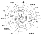
- FIG. 5 is a diagram in which the bypass mechanism is removed in the fixed scroll of FIG.
- FIG. 6 is a view of the fixed scroll as viewed from the suction side.
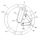
- FIG. 3 is a view of the fixed scroll as viewed from the discharge side.
- the first valve retainer 812 and the second valve retainer 822 are omitted from the bypass mechanism.
- the area of the first valve 811 and the second valve 821 is smaller than that of the discharge valve 44, and the area is divided into two by the center line L along the longitudinal direction of the discharge valve 44. It is located in one of the areas.
- the first valve 811 and the second valve 821 have a "C" shape in which the distance between the valves becomes wider toward the side fixed by the first fixing member 813 and the second fixing member 823. Have been placed. That is, the distance D1 between the first fixing member 813 and the second fixing member 823 is arranged so as to be longer than the distance D2 between the first communication hole 415 and the second communication hole 416. ing.
- the discharge valve 44 occupies a large area in the disk portion 4111 of the fixed scroll 41 and is arranged in the center.
- the bypass mechanism that opens and closes according to the pressure relationship between the suction side space 46 and the discharge side space 47 requires a relatively large communication hole and valve in order to sufficiently release the pressure. It is difficult to provide a valve due to the discharge valve 44 in terms of space. Therefore, by providing a plurality of communication holes (first communication hole 415, second communication hole 416), a sufficient total flow path area is secured, and these valves (first valve 811 and second valve 821) are provided. ) Is reduced in area.
- the distance D2 between the first communication hole 415 and the second communication hole 416 is wider than the distance D1 between the first fixing member 813 and the second fixing member 823.
- the shape allows the first valve 811 and the second valve 821 to fit within the half region divided by the discharge valve 44 while avoiding contact with the discharge valve 44. Even if the distance D1 is replaced with the first fixing hole 417 and the second fixing hole 418, the obtained effects are the same.
- the first communication hole 415 and the second communication hole 416 extend a spiral from the spiral end portion 4221 located on the outer end side of the spiral tooth 422 of the swing scroll 42. It is provided in the disk portion 4111 of the fixed scroll 41 corresponding to the area 425. Further, four straight lines A formed by connecting the spiral end portion 4121 of the fixed scroll 41 and the spiral end portion 4221 of the swing scroll 42, and a straight line B which is a perpendicular line to the straight line A and passes through the discharge port 413.
- the region is defined as the first quadrant, the second quadrant, the third quadrant, and the fourth quadrant in the direction extending the spiral from the spiral end portion 4221 of the swing scroll 42, the first communication hole 415 and the second communication hole 415 and the second quadrant, respectively.
- the communication hole 416 is provided in the first quadrant. Further, the first communication hole 415 and the second communication hole 416 are provided along the wall of the spiral tooth 412 of the fixed scroll 41. Specifically, a straight line C passing through the first communication hole 415 and the second communication hole 416 is provided substantially in parallel along the wall outer wall of the spiral tooth 412.
- the region 425 and the first quadrant are relatively space portions in the disk portion 4111 even when the spiral teeth 412 of the fixed scroll 41 and the spiral teeth 422 of the swing scroll 42 are combined, and any timing of the compression process. However, since the position is not blocked by the swing scroll 42, it is most suitable as a place where the first communication hole 415 and the second communication hole 416 are formed. However, since the region 425 and the first quadrant are not large even if they have a relatively large space, the first communication hole 415 and the second communication hole 416 are not in the radial direction of the disk portion 4111 but in the circumferential direction. It is possible to avoid interference between the first communication hole 415 and the second communication hole 416.
- the first communication hole 415 and the second communication hole 416 are located in a region 426 extending a spiral from the spiral end portion 4121 located on the outer end side of the spiral tooth 422 of the swing scroll 42, that is, in the third quadrant. May be provided along the outer wall of the spiral teeth 422 of the swing scroll 42. However, since the area 425 is wider than the area 426, the present embodiment is more desirable.
- the refrigerant for compression in the compression mechanism unit 4 is sucked into the shell 1 from the suction pipe 14, and reaches the refrigerant intake space through the suction port 21 of the main frame 2. Then, the refrigerant is taken into the compression chamber 45 of the compression mechanism unit 4, and is compressed by reducing the volume while moving from the outer peripheral portion toward the center along with the eccentric revolution motion of the rocking scroll 42. The compressed refrigerant is discharged from the discharge port 413 of the fixed scroll 41 against the discharge valve 44, and is discharged to the outside of the shell 1 via the discharge pipe 15.
- the pressure in the discharge side space 47 is higher than the pressure in the suction side space 46. That is, since the discharge side space 47 is a high pressure space and the suction side space 46 is a low pressure space, pressure acts on the first valve 811 and the second valve 821 from the discharge side, and the first valve is as shown in FIG.
- the communication hole 415 and the second communication hole 416 are in close contact with the valve seat of the fixed scroll 41 on the discharge side, and the bypass passage is closed. Even in a state where the pressures of the discharge side space 47 and the suction side space 46 at the time of stopping are equalized, the first valve 811 and the second valve 821 are in the closed state. In this state, the main frame 2 fixed to the stepped portion 111 of the middle shell 11 is pressed against the stepped portion 111 by a pressure difference, so that the state at the time of assembly is always maintained.
- a check valve or the like is usually arranged at the liquid reservoir inlet or the extension destination of the discharge pipe 15 in the refrigerant cycle.
- the pressure on the discharge side space 47 side drops due to the influence of the condenser ambient temperature
- the suction side space 46 side the refrigerant in the liquid reservoir evaporates and the pressure rises due to the influence of the compressor ambient temperature, and the pressure rises on the discharge side.
- the pressure in the suction side space 46 is higher than that in the space 47, which is a so-called high / low pressure reversal state.
- the high / low pressure reversal state may occur for a moment even when the refrigerant gas is suddenly filled during the airtightness test.
- a force that lifts the first valve 811 and the second valve 821 from the lower side to the upper side acts, and the first valve 811 and the second valve 821 communicate with each other.
- a bypass passage between the suction side space 46 and the discharge side space 47 will be opened.
- a compression chamber is formed by a main frame 2 provided in the shell 1, a spiral tooth 412 of the fixed scroll 41 and a spiral tooth 422 of the swing scroll 42 supported by the main frame 2.
- a first communication hole 415 and a second communication hole 415 and a second communication hole 415 and a second communication hole 415 provided in the fixed scroll 41 and communicating the suction side space 46 and the discharge side space 47 with the compression mechanism unit 4 for compressing and discharging the sucked refrigerant by 45.
- a second communication hole 416 and a second communication hole 416 provided on the discharge side of the fixed scroll 41 to open the first communication hole 415 and the second communication hole 416 when the pressure on the suction side becomes larger than the pressure on the discharge side.
- 1 valve 811 and 2nd valve 812, 1st fixing member 813 for fixing the 1st valve 811 to the fixed scroll 41, and 2nd valve 821 are fixed to the fixed scroll 41, and the 1st fixing member A second fixing member 823, wherein the distance D1 to the 813 is longer than the distance D2 between the first communication hole 415 and the second communication hole 416 is provided.
- the discharge valve 44 and the like can be arranged without contacting the first valve 811 and the second valve 821.
- the distance D1 and the distance D2 may have an obtuse angle as in the second and third embodiments.
- the first communication hole 415 and the second communication hole 416 form a fixed scroll 41 corresponding to a region 425 extending from the spiral end portion 4221 which is the outer end side end portion of the spiral tooth 422 of the swing scroll 42. Since it is provided, the first communication hole 415 and the second communication hole 416 are not blocked by the swing scroll 42 regardless of the driving state of the compression mechanism unit 4, and the openings are always secured without pressure loss. The pressure can be released stably.
- the first valve 811 and the second valve 821 have a smaller area when viewed from the discharge side space 47 than the discharge valve 44, and are divided into two by a center line L along the longitudinal direction of the discharge valve 44.
- the fixed scroll 41 is arranged in one of the discharge-side areas of the fixed scroll 41.
- the first communication hole 415 and the second communication hole 415 and the second communication hole 415 are provided. It is possible to secure a sufficient hole size in a limited space to release the pressure at the time of high and low pressure reversal without the communication holes 416 interfering with each other.
- FIG. 7 is a diagram for explaining the scroll compressor according to the second embodiment of the present invention.
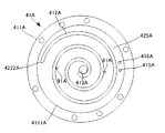
- FIG. 8 is a view of the fixed scroll of FIG. 7 as viewed from the suction side.
- parts having the same configuration as the scroll compressors of FIGS. 1 to 6 are designated by the same reference numerals, and the description thereof will be omitted.
- the fixed scroll 41A includes a pair of third communication holes 91A for communicating the suction side space 46 and the discharge side space 47 with the disk portion 4111A.
- the third communication hole 91A is an injection port that injects the refrigerant into the compression chamber 45 in the compression process.
- the third communication hole 91A is formed so as to be located in the intermediate pressure compression chamber which is the intermediate pressure in the compression chamber 45, and the refrigerant in the compression chamber is used. It is a hole for injecting a refrigerant in the middle of the refrigeration cycle, for example, a refrigerant branched from between the condenser and the expansion valve according to the pressure and temperature.
- the refrigerant supplied to the third communication hole 91A during the refrigeration cycle is inserted and fixed in the pipe fixing hole 92A provided in the disk portion 4111A of the fixed scroll 41A, one end in the pipe fixing hole 92A, and the other end in the shell 1.
- An injection pipe (not shown) that extends to the outside of the compressor via a pipe and connects to a pipe branched from between the condenser and the expansion valve, and a pipe fixing hole 92A and a third pipe fixing hole 92A provided in the base plate 411A of the fixed scroll 41A. It is performed by a horizontal hole (not shown) connecting the communication hole 91A of the above.
- a pair of third communication holes 91A is provided, but the number of holes can be arbitrarily changed.
- the angle ⁇ formed by the straight line D connecting the first communication hole 415A and the first fixing hole 417A and the straight line E connecting the second communication hole 416A and the second fixing hole 418A is obtuse. Is set to. That is, since the third communication hole 91A, which is the intermediate pressure injection port, is provided between the discharge port 413A and the first communication hole 415A and the second communication hole 416A, the first fixing hole 417A and the second communication hole 91A are provided. By providing the fixing hole 418A of No.
- the valve and the discharge valve 44A and the third communication can be communicated with each other. Interference with the hole 91A and the pipe fixing hole 92A can be avoided.
- the first fixing hole 417A and the second fixing hole 418A may be replaced with a fixing member which is inserted and connected to each of the holes in order to fix the valve.
- FIG. 9 is a diagram for explaining the scroll compressor according to the third embodiment of the present invention.
- FIG. 10 is a diagram in which a valve is provided in FIG.
- the fixed scroll 41B has a third valve 94B that is openably and closably provided on the discharge side of the third communication hole 93B that communicates the suction side space 46 and the discharge side space 47 with the disk portion 4111B.
- the third communication hole 93B is a third communication hole 93B in the compression chamber 45 during the compression process when the pressure of the refrigerant is equal to or lower than the preset pressure and the third valve 94B is closed and becomes equal to or higher than the preset pressure. This is a relief port in which the valve 94B is opened and the refrigerant is released to the discharge side.
- the third valve 94B is fixed to the disk portion 4111B of the fixed scroll 41B together with the valve retainer (not shown).
- the space of the disk portion 4111A of the fixed scroll 41A becomes even tighter, but the first communication hole 415B and the first fixing hole are the same as in the second embodiment.
- the angle ⁇ formed by the straight line D connecting the 417B and the straight line E connecting the second communication hole 416B and the second fixing hole 418B is an obtuse angle, the first valve 811B and the second valve 811B and the second.
- a third communication hole 91A for the injection port of the second embodiment may be further provided, and even in this case, interference can be avoided.
- the present invention is not limited to the invention according to the above embodiment, and can be appropriately modified as long as the gist of the present invention is not deviated.
- the first communication hole 415 and the second communication hole 416 are not limited to two, but may be three or more. In that case, as many valves as there are communication holes are provided. Depending on the number of communication holes, the pressure at which the refrigerant can be relieved at the time of high / low pressure reversal can be adjusted.
- the fixed scroll 41C may be provided with the chamber 4115C on the discharge side of the base plate 411C.
- the first communication hole 415C is formed so as to communicate the base plate 411C and the chamber 4115C.
- the discharge hole 4116C formed in the chamber 4115C is formed so as to communicate with the discharge port 413C.
Landscapes
- Engineering & Computer Science (AREA)
- Mechanical Engineering (AREA)
- General Engineering & Computer Science (AREA)
- Rotary Pumps (AREA)
- Applications Or Details Of Rotary Compressors (AREA)
Priority Applications (3)
| Application Number | Priority Date | Filing Date | Title |
|---|---|---|---|
| CN202090001131.0U CN218542593U (zh) | 2020-03-27 | 2020-03-27 | 涡旋压缩机 |
| PCT/JP2020/014084 WO2021192238A1 (ja) | 2020-03-27 | 2020-03-27 | スクロール圧縮機 |
| JP2022510340A JP7366238B2 (ja) | 2020-03-27 | 2020-03-27 | スクロール圧縮機 |
Applications Claiming Priority (1)
| Application Number | Priority Date | Filing Date | Title |
|---|---|---|---|
| PCT/JP2020/014084 WO2021192238A1 (ja) | 2020-03-27 | 2020-03-27 | スクロール圧縮機 |
Publications (1)
| Publication Number | Publication Date |
|---|---|
| WO2021192238A1 true WO2021192238A1 (ja) | 2021-09-30 |
Family
ID=77891644
Family Applications (1)
| Application Number | Title | Priority Date | Filing Date |
|---|---|---|---|
| PCT/JP2020/014084 Ceased WO2021192238A1 (ja) | 2020-03-27 | 2020-03-27 | スクロール圧縮機 |
Country Status (3)
| Country | Link |
|---|---|
| JP (1) | JP7366238B2 (https=) |
| CN (1) | CN218542593U (https=) |
| WO (1) | WO2021192238A1 (https=) |
Cited By (3)
| Publication number | Priority date | Publication date | Assignee | Title |
|---|---|---|---|---|
| CN117501013A (zh) * | 2021-12-23 | 2024-02-02 | 翰昂汽车零部件有限公司 | 用于压缩气态流体的装置以及用于操作该装置的方法 |
| CN117627920A (zh) * | 2022-08-17 | 2024-03-01 | 日立江森自控空调有限公司 | 压缩机 |
| US11982275B2 (en) * | 2022-07-27 | 2024-05-14 | Lg Electronics Inc. | Scroll compressor including grooved discharge and bypass valve arrangement |
Citations (4)
| Publication number | Priority date | Publication date | Assignee | Title |
|---|---|---|---|---|
| JPH09170574A (ja) * | 1995-12-21 | 1997-06-30 | Matsushita Electric Ind Co Ltd | スクロール気体圧縮機 |
| JP2005264752A (ja) * | 2004-03-16 | 2005-09-29 | Mitsubishi Electric Corp | スクロール圧縮機 |
| US20070217938A1 (en) * | 2006-03-14 | 2007-09-20 | Lg Electronics Inc. | Scroll compressor with bypass apparatus |
| JP2017155719A (ja) * | 2016-03-04 | 2017-09-07 | 三菱重工業株式会社 | 圧縮機 |
Family Cites Families (1)
| Publication number | Priority date | Publication date | Assignee | Title |
|---|---|---|---|---|
| JPS6117491U (ja) * | 1984-07-09 | 1986-01-31 | 三菱重工業株式会社 | スクロ−ル型流体機械 |
-
2020
- 2020-03-27 CN CN202090001131.0U patent/CN218542593U/zh active Active
- 2020-03-27 JP JP2022510340A patent/JP7366238B2/ja active Active
- 2020-03-27 WO PCT/JP2020/014084 patent/WO2021192238A1/ja not_active Ceased
Patent Citations (4)
| Publication number | Priority date | Publication date | Assignee | Title |
|---|---|---|---|---|
| JPH09170574A (ja) * | 1995-12-21 | 1997-06-30 | Matsushita Electric Ind Co Ltd | スクロール気体圧縮機 |
| JP2005264752A (ja) * | 2004-03-16 | 2005-09-29 | Mitsubishi Electric Corp | スクロール圧縮機 |
| US20070217938A1 (en) * | 2006-03-14 | 2007-09-20 | Lg Electronics Inc. | Scroll compressor with bypass apparatus |
| JP2017155719A (ja) * | 2016-03-04 | 2017-09-07 | 三菱重工業株式会社 | 圧縮機 |
Cited By (6)
| Publication number | Priority date | Publication date | Assignee | Title |
|---|---|---|---|---|
| CN117501013A (zh) * | 2021-12-23 | 2024-02-02 | 翰昂汽车零部件有限公司 | 用于压缩气态流体的装置以及用于操作该装置的方法 |
| JP2024544107A (ja) * | 2021-12-23 | 2024-11-28 | ハンオン システムズ | 気相流体を圧縮するための装置及びその操作方法 |
| US12480493B2 (en) | 2021-12-23 | 2025-11-25 | Hanon Systems | Device for compressing a gaseous fluid and method for operating the device |
| JP7836336B2 (ja) | 2021-12-23 | 2026-03-26 | ハンオン システムズ | 気相流体を圧縮するための装置及びその操作方法 |
| US11982275B2 (en) * | 2022-07-27 | 2024-05-14 | Lg Electronics Inc. | Scroll compressor including grooved discharge and bypass valve arrangement |
| CN117627920A (zh) * | 2022-08-17 | 2024-03-01 | 日立江森自控空调有限公司 | 压缩机 |
Also Published As
| Publication number | Publication date |
|---|---|
| CN218542593U (zh) | 2023-02-28 |
| JP7366238B2 (ja) | 2023-10-20 |
| JPWO2021192238A1 (https=) | 2021-09-30 |
Similar Documents
| Publication | Publication Date | Title |
|---|---|---|
| JP4329528B2 (ja) | スクロールコンプレッサ | |
| WO2021192238A1 (ja) | スクロール圧縮機 | |
| WO2018042852A1 (ja) | スクロール圧縮機 | |
| WO2021186499A1 (ja) | 圧縮機 | |
| JPWO2020148857A1 (ja) | スクロール圧縮機 | |
| KR20060051788A (ko) | 압축기 | |
| JPWO2019207759A1 (ja) | スクロール圧縮機 | |
| WO2023214561A1 (ja) | 圧縮機 | |
| JP7395004B2 (ja) | スクロール圧縮機 | |
| JP2011021511A (ja) | スクロール圧縮機 | |
| JP2008138526A (ja) | 圧縮機 | |
| CN116157600B (zh) | 涡旋压缩机 | |
| GB2626466A (en) | Scroll compressor and method for manufacturing same | |
| JP7350101B2 (ja) | スクロール圧縮機 | |
| JP2009002352A (ja) | 圧縮機 | |
| JP7076537B2 (ja) | スクロール圧縮機 | |
| JP4792947B2 (ja) | 圧縮機 | |
| JP2021038684A (ja) | スクロール圧縮機 | |
| WO2019207785A1 (ja) | スクロール圧縮機 | |
| WO2023188422A1 (ja) | 圧縮機およびアッパーシェル | |
| WO2023276020A1 (ja) | スクロール圧縮機 | |
| WO2026069996A1 (ja) | ロータリ圧縮機 | |
| KR20250036305A (ko) | 스크롤 압축기 | |
| WO2021024907A1 (ja) | スクロール圧縮機 | |
| JP2006132348A (ja) | 圧縮機 |
Legal Events
| Date | Code | Title | Description |
|---|---|---|---|
| 121 | Ep: the epo has been informed by wipo that ep was designated in this application |
Ref document number: 20927567 Country of ref document: EP Kind code of ref document: A1 |
|
| ENP | Entry into the national phase |
Ref document number: 2022510340 Country of ref document: JP Kind code of ref document: A |
|
| NENP | Non-entry into the national phase |
Ref country code: DE |
|
| 122 | Ep: pct application non-entry in european phase |
Ref document number: 20927567 Country of ref document: EP Kind code of ref document: A1 |