WO2021192238A1 - スクロール圧縮機 - Google Patents
スクロール圧縮機 Download PDFInfo
- Publication number
- WO2021192238A1 WO2021192238A1 PCT/JP2020/014084 JP2020014084W WO2021192238A1 WO 2021192238 A1 WO2021192238 A1 WO 2021192238A1 JP 2020014084 W JP2020014084 W JP 2020014084W WO 2021192238 A1 WO2021192238 A1 WO 2021192238A1
- Authority
- WO
- WIPO (PCT)
- Prior art keywords
- valve
- scroll
- communication hole
- fixed scroll
- discharge
- Prior art date
Links
Images


Classifications
-
- F—MECHANICAL ENGINEERING; LIGHTING; HEATING; WEAPONS; BLASTING
- F04—POSITIVE - DISPLACEMENT MACHINES FOR LIQUIDS; PUMPS FOR LIQUIDS OR ELASTIC FLUIDS
- F04C—ROTARY-PISTON, OR OSCILLATING-PISTON, POSITIVE-DISPLACEMENT MACHINES FOR LIQUIDS; ROTARY-PISTON, OR OSCILLATING-PISTON, POSITIVE-DISPLACEMENT PUMPS
- F04C18/00—Rotary-piston pumps specially adapted for elastic fluids
- F04C18/02—Rotary-piston pumps specially adapted for elastic fluids of arcuate-engagement type, i.e. with circular translatory movement of co-operating members, each member having the same number of teeth or tooth-equivalents
-
- F—MECHANICAL ENGINEERING; LIGHTING; HEATING; WEAPONS; BLASTING
- F04—POSITIVE - DISPLACEMENT MACHINES FOR LIQUIDS; PUMPS FOR LIQUIDS OR ELASTIC FLUIDS
- F04C—ROTARY-PISTON, OR OSCILLATING-PISTON, POSITIVE-DISPLACEMENT MACHINES FOR LIQUIDS; ROTARY-PISTON, OR OSCILLATING-PISTON, POSITIVE-DISPLACEMENT PUMPS
- F04C29/00—Component parts, details or accessories of pumps or pumping installations, not provided for in groups F04C18/00 - F04C28/00
- F04C29/12—Arrangements for admission or discharge of the working fluid, e.g. constructional features of the inlet or outlet
Definitions
- the present disclosure relates to a scroll compressor that employs a bypass mechanism that releases pressure when a high-low pressure reversal occurs.
- the scroll compressor compresses the refrigerant sucked from the suction pipe in a compression chamber formed in the compression mechanism and discharges it.
- the pressure in the space on the side that sucks in the refrigerant is lower than that in the space on the side that discharges the refrigerant.
- the frame may shift.
- a ball valve provided in a communication hole that communicates a high-pressure space in which a high-pressure refrigerant gas compressed by a compression mechanism is discharged and a low-pressure space in an suction pressure atmosphere, and a ball valve.
- the scroll compressor is provided with a bypass mechanism composed of a chamber that suppresses the movement of the gas into a high-pressure space.
- the prior art of Patent Document 1 describes a bypass mechanism using a valve.
- the bypass mechanism using a ball valve it is necessary to arrange the chamber so as to cover the communication hole in order to prevent the steel ball from jumping out into the high pressure space. Further, in the bypass mechanism using a valve, the ability to release the pressure when the high and low pressure reversal occurs depends on the diameter of the hole, but when the diameter of the hole is increased, the valve body also becomes large. Therefore, for example, when the injection mechanism is provided on the base plate of the fixed scroll, the valve may not be provided in contact with the injection mechanism.
- This disclosure is made in order to solve the above-mentioned problems, and a scroll capable of providing a bypass mechanism regardless of the specifications of the compressor and sufficiently releasing the pressure at the time of high and low pressure reversal.
- the purpose is to provide a compressor.
- the scroll compressor according to the present disclosure is sucked by a main frame provided in a shell and a compression chamber supported by the main frame and formed by spiral teeth of a fixed scroll and spiral teeth of a swing scroll.
- a compression mechanism unit that compresses and discharges the generated refrigerant, first and second communication holes provided in the fixed scroll and communicating the space on the suction side and the space on the discharge side, and the discharge of the fixed scroll.
- the first and second valves provided on the side and opening the first and second communication holes when the pressure on the suction side becomes larger than the pressure on the discharge side, and the first valve.
- the distance between the first fixing member that fixes the valve to the fixed scroll and the first fixing member that fixes the second valve to the fixed scroll is the first and second communication holes.
- a second fixing member which is longer than the distance between them, is provided.
- the bypass mechanism is composed of a plurality of communication holes, valves and fixing members, and the distance between the first and second fixing members of the fixed scroll is the distance between the first and second communication holes. Even if the fixed scroll space is limited by the discharge valve, etc., while ensuring the area of the hole that allows the refrigerant to escape sufficiently during high and low pressure reversal, there are multiple discharge valves, etc. It can be placed without interfering with the valve.
- FIG. 2 is a diagram when the valve is in the open state. It is the figure which looked at the fixed scroll from the discharge side. It is the figure which removed the bypass mechanism in the fixed scroll of FIG. It is the figure which looked at the fixed scroll from the suction side. It is a figure for demonstrating the scroll compressor which concerns on Embodiment 2 of this invention.
- FIG. 7 is a view of the fixed scroll of FIG. 7 as viewed from the suction side. It is a figure for demonstrating the scroll compressor which concerns on Embodiment 3 of this invention.
- 9 is a diagram in which a valve is provided in FIG. It is a figure for demonstrating the scroll compressor which concerns on Embodiment 4 of this invention.
- FIG. 1 is a diagram for explaining the scroll compressor according to the first embodiment of the present invention.
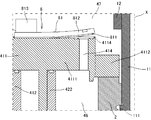
- FIG. 2 is an enlarged view of the region X of the alternate long and short dash line of FIG.
- FIG. 3 is a view when the valve is in the open state in FIG.
- the main frame, the compression mechanism unit, the drive mechanism unit, and the like are shown in a cross-sectional view, but a partial configuration of the crankshaft and the like is an external view.
- the scroll compressor includes a shell 1, a main frame 2, a thrust plate 3, a compression mechanism unit 4, a drive mechanism unit 5, a subframe 6, a crankshaft 7, and a bypass mechanism 8. ..
- the compressor of the first embodiment is a so-called vertical scroll compressor used in a state where the central axis of the crankshaft 7 is substantially perpendicular to the ground. Further, it is a so-called low-pressure shell type scroll compressor in which the pressure in the space in the shell 1 in which the drive mechanism unit 5 is arranged becomes lower than the pressure in the discharge space in the upper shell 12.
- the shell 1 is a tubular housing made of a conductive member such as metal, and includes a middle shell 11, an upper shell 12, a lower shell 13, a suction pipe 14, a discharge pipe 15, and a fixing base 16.
- the middle shell 11 is a cylindrical tube.
- the upper shell 12 is a substantially hemispherical lid, and a part of the upper shell 12 is connected by welding or the like on the upper side of the middle shell 11 to close one opening of the middle shell 11.
- the lower shell 13 is a substantially hemispherical bottom body, and a part of the lower shell 13 is connected to the lower side of the middle shell 11 by welding or the like to close the other opening of the middle shell 11.
- the suction pipe 14 is a pipe for sucking a refrigerant containing a refrigerant and a lubricating oil into the shell 1, and is connected by welding or the like with a part inserted into a hole formed in the middle shell 11. ..
- the discharge pipe 15 is a pipe for discharging the refrigerant to the outside of the shell 1, and is connected to the hole provided in the upper shell 12 by welding or the like with a part inserted.
- the fixed base 16 is a support base that supports the shell 1.
- the fixing base 16 has a plurality of legs, and by fixing the legs with screws, the scroll compressor can be fixed to other members such as the housing of the air conditioner outdoor unit.
- the shell 1 is provided with a power feeding unit for supplying power to the scroll compressor.
- the main frame 2 is a cylindrical metal frame that swingably holds the swing scroll 42 of the compression mechanism portion 4, and the lower portion thereof is configured as a bearing that supports the crankshaft 7.
- the main frame 2 is fixed to the middle shell 11 by shrink fitting or the like while being placed on the step portion 111 formed inside the shell 1, specifically, the upper inner circumference of the middle shell 11.
- a space penetrating in the vertical direction is formed in the center, and a suction port 21 for supplying a refrigerant to the compression mechanism portion 4 is formed.
- a return pipe 22 for discharging the refrigerating machine oil accumulated in the space is provided in the lower part of the main frame 2.
- a balancer cover 23 is provided on the lower end side of the main frame 2 so as to cover the balancer 73 described later.
- the thrust plate 3 is a thin metal plate of a steel plate system that functions as a thrust bearing, is arranged on the main frame 2, and supports the thrust load of the compression mechanism portion 4.
- the thrust plate 3 is shaped so as not to interfere with the suction of the refrigerant from the suction port 21.
- the compression mechanism unit 4 is a compression mechanism that is supported by the main frame 2, is sucked from the suction pipe 14, and compresses the refrigerant that has passed through the suction port 21.
- the compression mechanism unit 4 includes a fixed scroll 41, a swing scroll 42, an old dam ring 43, and a discharge valve 44, and the compression chamber 45 is formed by these scrolls.
- the lower side thereof is defined as the suction side
- the space thereof is defined as the suction side space 46
- the upper side is defined as the discharge side
- the space is defined as the discharge side space 47.
- the fixed scroll 41 is made of a metal such as cast iron, and has a base plate 411, a spiral tooth 412, a discharge port 413, a fixing hole 414, a first communication hole 415, a second communication hole 416, and a first.
- a fixing hole 417 and a second fixing hole 418 are provided.
- the base plate 411 is disk-shaped and convex, and includes a disk portion 4111 located at the center portion and a collar portion 4112 fixed to the main frame 2 and bolted in the vicinity of the outer periphery of the disk portion 4111.
- the spiral tooth 412 is a spiral tooth formed by projecting from one surface in the disk portion 4111 of the base plate 411.
- the discharge port 413 is a hole for discharging the refrigerant compressed in the compression chamber 45, and is provided at substantially the center of the disk portion 4111 of the base plate 411 so as to communicate the suction side space 46 and the discharge side space 47.
- the fixing hole 414 is a hole provided in the vicinity of the discharge port 413.
- the discharge port 413 and the fixing hole 414 are provided in the recess 4113 formed by being recessed in the direction of the spiral teeth 412 on the discharge side surface of the disk portion 4111.
- the first communication hole 415 is provided near the outer end of the disk portion 4111 of the base plate 411 and is a hole that communicates with the suction side space 46 and the discharge side space 47.
- the second communication hole 416 is a hole similar to the first communication hole 415.
- the first fixing hole 417 is a hole provided in the vicinity of the first communication hole 415 in the disk portion 4111 of the base plate 411.
- the first communication hole 415 and the first fixing hole 417 are provided in the recess 4114 formed by being recessed in the direction of the spiral teeth 412 on the discharge side surface of the disk portion 4111.
- the second fixing hole 418 is a hole similar to the first fixing hole 417.
- the valve seat around the discharge port 413, the first communication hole 415, and the second communication hole 416 has an annular groove for reducing the oil film breaking resistance between the valve seat and the valve when the valve is opened and closed. Is provided.
- the swing scroll 42 is made of a metal such as aluminum, and includes a base plate 421, spiral teeth 422, a cylindrical portion 423, and an Oldham groove 424.
- the base plate 421 is a disk-shaped flange.
- the spiral tooth 422 is a spiral tooth formed so as to project from one surface of the base plate 421.
- the tubular portion 423 is a cylinder formed so as to project from substantially the center of the other surface of the base plate 421.
- On the inner peripheral surface of the tubular portion 423 a swing bearing that rotatably supports the bush 75, which will be described later, a so-called journal bearing is provided so that its central axis is parallel to the central axis of the crankshaft 7. ..
- the Oldham groove 424 is a groove formed on the back surface of the base plate 421 on the other surface.
- a tip seal made of hard plastic is provided at the tip of the tooth of the fixed scroll 41 and the swing scroll 42.
- the old dam ring 43 is a member for preventing the swing scroll 42 from rotating.
- the Oldham ring 43 includes a pair of keys on one side and a pair of keys on the other side, one key is housed in the Oldham groove 424 of the swing scroll 42, and the other key is formed in the mainframe 2. It is housed in a keyway.
- the discharge valve 44 is a valve that opens and closes the discharge port 413, and when the refrigerant in the compression chamber 45 communicating with the discharge port 413 reaches a predetermined pressure, the discharge valve 44 is changed from the closed state to the open state.
- the discharge valve 44 is arranged in the recess 4113 of the disk portion 4111 of the fixed scroll 41, and is fixed with a screw to fix the hole 414 together with a valve retainer (not shown) for adjusting the opening degree of the valve and preventing the root of the valve from cracking. It is tightened together.
- the compression chamber 45 is formed by the spiral teeth 412 of the fixed scroll 41 and the spiral teeth 422 of the swing scroll 42. More specifically, the compression chamber 45 meshes the spiral teeth 412 of the fixed scroll 41 and the spiral teeth 422 of the swing scroll 42 with each other, and also includes the tip of the spiral body, the tip seal and the base plate. Formed by sealing with.
- the compression chamber 45 is composed of a plurality of compression chambers whose volume decreases from the outside to the inside in the radial direction of the scroll.
- a halogenated hydrocarbon having a carbon double bond for example, a halogenated hydrocarbon having no carbon double bond, a natural refrigerant, or a mixture containing them can be used in the composition.
- R32 CH2F2
- R410A R32 / R125
- the drive mechanism unit 5 is provided below the main frame 2.
- the drive mechanism unit 5 includes a stator 51 and a rotor 52.
- the stator 51 is, for example, a ring-shaped stator formed by winding windings around an iron core formed by laminating a plurality of electromagnetic steel sheets via an insulating layer, and is fixed to the inner wall of the middle shell 11 by shrink fitting or the like.
- the rotor 52 is a cylindrical rotor having a permanent magnet built in an iron core formed by laminating a plurality of electromagnetic steel plates and having a through hole penetrating in the vertical direction in the center, and is arranged in the internal space of the stator 51. ing.
- the subframe 6 is a metal frame, which is provided on the lower side of the drive mechanism portion 5 and is fixed to the inner wall of the middle shell 11 by shrink fitting, welding, or the like.
- the subframe 6 includes an auxiliary bearing portion 61 and an oil pump 62.
- the sub-bearing portion 61 is a ball bearing provided on the upper center of the sub-frame 6.
- the oil pump 62 is a pump for sucking up lubricating oil, and is provided on the lower center side of the subframe 6.
- Lubricating oil is stored in the lower shell 13 at the bottom of the shell 1, is sucked up by the oil pump 62, passes through the crankshaft 7, is supplied to the compression mechanism 4 and the like, and wears between parts that come into mechanical contact with each other. Reduces, adjusts the temperature of sliding parts, and improves sealing performance.
- As the lubricating oil an oil having excellent lubrication characteristics, electrical insulation, stability, refrigerant solubility, low-temperature fluidity and the like, and having an appropriate viscosity is suitable.
- naphthenic, polyol ester (POE), polyvinyl ether (PVE), polyalkylene glycol (PAG) oils can be used.
- the crankshaft 7 is a metal rod-shaped member, which is provided inside the shell 1.
- the crankshaft 7 includes a spindle portion 71, an eccentric shaft portion 72, a balancer 73, an oil passage 74, and a bush 75.
- the spindle portion 71 is a shaft that constitutes the main portion of the crankshaft 7, is fixed to a through hole at the center of the rotor 52 by shrink fitting or the like, and is arranged so that the central axis coincides with the central axis of the middle shell 11. ing.
- the eccentric shaft portion 72 is provided on the upper side of the spindle portion 71 so that the central shaft thereof is eccentric with respect to the central axis of the spindle portion 71.
- the balancer 73 is provided on the outer periphery of the spindle portion 71 and is covered with the balancer cover 23.
- the oil passage 74 is provided inside the main shaft portion 71 and the eccentric shaft portion 72 so as to penetrate vertically along the axial direction.
- the bush 75 is made of a metal such as iron, and is a member that connects the eccentric shaft portion 72 and the cylindrical portion 423 of the swing scroll 42 and absorbs the imbalance of the load generated during swing.
- the bypass mechanism 8 is composed of a first bypass mechanism 81 and a second bypass mechanism 82.
- the first bypass mechanism 81 includes a first valve 811, a first valve retainer 812, and a first fixing member 813.
- the second bypass mechanism 82 includes a second valve 821, a second valve retainer 822, and a second fixing member 823.
- the first valve 811 is arranged in the recess 4114 of the disk portion 4111 of the fixed scroll 41.
- the first valve 811 can open and close the first communication hole 415, and closes the first communication hole 415 according to the pressure relationship between the suction side space 46 and the discharge side space 47 as shown in FIG. It is a relief valve that can be opened and moved as shown in FIG.
- the first valve retainer 812 is a member for adjusting the opening degree of the valve when the first valve 811 is opened and preventing the root crack of the valve. Therefore, the first valve retainer 812 is configured to have a higher strength than the first valve 811.
- the first valve retainer 812 is made of a material that is thicker or harder than the first valve 811.
- the first fixing member 813 is a screw that fastens the first valve 811 and the first valve retainer 812 together with the discharge side of the fixed scroll 41, and is screwed into the first fixing hole 417.
- the second valve 821, the second valve retainer 822, and the second fixing member 823 of the second bypass mechanism 82 are the same as the first valve 811, the first valve retainer 812, and the first fixing member 813, respectively. Since it is the structure of, the description is omitted.
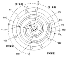
- FIG. 4 is a view of the fixed scroll as viewed from the suction side.
- FIG. 5 is a diagram in which the bypass mechanism is removed in the fixed scroll of FIG.
- FIG. 6 is a view of the fixed scroll as viewed from the suction side.
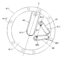
- FIG. 3 is a view of the fixed scroll as viewed from the discharge side.
- the first valve retainer 812 and the second valve retainer 822 are omitted from the bypass mechanism.
- the area of the first valve 811 and the second valve 821 is smaller than that of the discharge valve 44, and the area is divided into two by the center line L along the longitudinal direction of the discharge valve 44. It is located in one of the areas.
- the first valve 811 and the second valve 821 have a "C" shape in which the distance between the valves becomes wider toward the side fixed by the first fixing member 813 and the second fixing member 823. Have been placed. That is, the distance D1 between the first fixing member 813 and the second fixing member 823 is arranged so as to be longer than the distance D2 between the first communication hole 415 and the second communication hole 416. ing.
- the discharge valve 44 occupies a large area in the disk portion 4111 of the fixed scroll 41 and is arranged in the center.
- the bypass mechanism that opens and closes according to the pressure relationship between the suction side space 46 and the discharge side space 47 requires a relatively large communication hole and valve in order to sufficiently release the pressure. It is difficult to provide a valve due to the discharge valve 44 in terms of space. Therefore, by providing a plurality of communication holes (first communication hole 415, second communication hole 416), a sufficient total flow path area is secured, and these valves (first valve 811 and second valve 821) are provided. ) Is reduced in area.
- the distance D2 between the first communication hole 415 and the second communication hole 416 is wider than the distance D1 between the first fixing member 813 and the second fixing member 823.
- the shape allows the first valve 811 and the second valve 821 to fit within the half region divided by the discharge valve 44 while avoiding contact with the discharge valve 44. Even if the distance D1 is replaced with the first fixing hole 417 and the second fixing hole 418, the obtained effects are the same.
- the first communication hole 415 and the second communication hole 416 extend a spiral from the spiral end portion 4221 located on the outer end side of the spiral tooth 422 of the swing scroll 42. It is provided in the disk portion 4111 of the fixed scroll 41 corresponding to the area 425. Further, four straight lines A formed by connecting the spiral end portion 4121 of the fixed scroll 41 and the spiral end portion 4221 of the swing scroll 42, and a straight line B which is a perpendicular line to the straight line A and passes through the discharge port 413.
- the region is defined as the first quadrant, the second quadrant, the third quadrant, and the fourth quadrant in the direction extending the spiral from the spiral end portion 4221 of the swing scroll 42, the first communication hole 415 and the second communication hole 415 and the second quadrant, respectively.
- the communication hole 416 is provided in the first quadrant. Further, the first communication hole 415 and the second communication hole 416 are provided along the wall of the spiral tooth 412 of the fixed scroll 41. Specifically, a straight line C passing through the first communication hole 415 and the second communication hole 416 is provided substantially in parallel along the wall outer wall of the spiral tooth 412.
- the region 425 and the first quadrant are relatively space portions in the disk portion 4111 even when the spiral teeth 412 of the fixed scroll 41 and the spiral teeth 422 of the swing scroll 42 are combined, and any timing of the compression process. However, since the position is not blocked by the swing scroll 42, it is most suitable as a place where the first communication hole 415 and the second communication hole 416 are formed. However, since the region 425 and the first quadrant are not large even if they have a relatively large space, the first communication hole 415 and the second communication hole 416 are not in the radial direction of the disk portion 4111 but in the circumferential direction. It is possible to avoid interference between the first communication hole 415 and the second communication hole 416.
- the first communication hole 415 and the second communication hole 416 are located in a region 426 extending a spiral from the spiral end portion 4121 located on the outer end side of the spiral tooth 422 of the swing scroll 42, that is, in the third quadrant. May be provided along the outer wall of the spiral teeth 422 of the swing scroll 42. However, since the area 425 is wider than the area 426, the present embodiment is more desirable.
- the refrigerant for compression in the compression mechanism unit 4 is sucked into the shell 1 from the suction pipe 14, and reaches the refrigerant intake space through the suction port 21 of the main frame 2. Then, the refrigerant is taken into the compression chamber 45 of the compression mechanism unit 4, and is compressed by reducing the volume while moving from the outer peripheral portion toward the center along with the eccentric revolution motion of the rocking scroll 42. The compressed refrigerant is discharged from the discharge port 413 of the fixed scroll 41 against the discharge valve 44, and is discharged to the outside of the shell 1 via the discharge pipe 15.
- the pressure in the discharge side space 47 is higher than the pressure in the suction side space 46. That is, since the discharge side space 47 is a high pressure space and the suction side space 46 is a low pressure space, pressure acts on the first valve 811 and the second valve 821 from the discharge side, and the first valve is as shown in FIG.
- the communication hole 415 and the second communication hole 416 are in close contact with the valve seat of the fixed scroll 41 on the discharge side, and the bypass passage is closed. Even in a state where the pressures of the discharge side space 47 and the suction side space 46 at the time of stopping are equalized, the first valve 811 and the second valve 821 are in the closed state. In this state, the main frame 2 fixed to the stepped portion 111 of the middle shell 11 is pressed against the stepped portion 111 by a pressure difference, so that the state at the time of assembly is always maintained.
- a check valve or the like is usually arranged at the liquid reservoir inlet or the extension destination of the discharge pipe 15 in the refrigerant cycle.
- the pressure on the discharge side space 47 side drops due to the influence of the condenser ambient temperature
- the suction side space 46 side the refrigerant in the liquid reservoir evaporates and the pressure rises due to the influence of the compressor ambient temperature, and the pressure rises on the discharge side.
- the pressure in the suction side space 46 is higher than that in the space 47, which is a so-called high / low pressure reversal state.
- the high / low pressure reversal state may occur for a moment even when the refrigerant gas is suddenly filled during the airtightness test.
- a force that lifts the first valve 811 and the second valve 821 from the lower side to the upper side acts, and the first valve 811 and the second valve 821 communicate with each other.
- a bypass passage between the suction side space 46 and the discharge side space 47 will be opened.
- a compression chamber is formed by a main frame 2 provided in the shell 1, a spiral tooth 412 of the fixed scroll 41 and a spiral tooth 422 of the swing scroll 42 supported by the main frame 2.
- a first communication hole 415 and a second communication hole 415 and a second communication hole 415 and a second communication hole 415 provided in the fixed scroll 41 and communicating the suction side space 46 and the discharge side space 47 with the compression mechanism unit 4 for compressing and discharging the sucked refrigerant by 45.
- a second communication hole 416 and a second communication hole 416 provided on the discharge side of the fixed scroll 41 to open the first communication hole 415 and the second communication hole 416 when the pressure on the suction side becomes larger than the pressure on the discharge side.
- 1 valve 811 and 2nd valve 812, 1st fixing member 813 for fixing the 1st valve 811 to the fixed scroll 41, and 2nd valve 821 are fixed to the fixed scroll 41, and the 1st fixing member A second fixing member 823, wherein the distance D1 to the 813 is longer than the distance D2 between the first communication hole 415 and the second communication hole 416 is provided.
- the discharge valve 44 and the like can be arranged without contacting the first valve 811 and the second valve 821.
- the distance D1 and the distance D2 may have an obtuse angle as in the second and third embodiments.
- the first communication hole 415 and the second communication hole 416 form a fixed scroll 41 corresponding to a region 425 extending from the spiral end portion 4221 which is the outer end side end portion of the spiral tooth 422 of the swing scroll 42. Since it is provided, the first communication hole 415 and the second communication hole 416 are not blocked by the swing scroll 42 regardless of the driving state of the compression mechanism unit 4, and the openings are always secured without pressure loss. The pressure can be released stably.
- the first valve 811 and the second valve 821 have a smaller area when viewed from the discharge side space 47 than the discharge valve 44, and are divided into two by a center line L along the longitudinal direction of the discharge valve 44.
- the fixed scroll 41 is arranged in one of the discharge-side areas of the fixed scroll 41.
- the first communication hole 415 and the second communication hole 415 and the second communication hole 415 are provided. It is possible to secure a sufficient hole size in a limited space to release the pressure at the time of high and low pressure reversal without the communication holes 416 interfering with each other.
- FIG. 7 is a diagram for explaining the scroll compressor according to the second embodiment of the present invention.
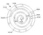
- FIG. 8 is a view of the fixed scroll of FIG. 7 as viewed from the suction side.
- parts having the same configuration as the scroll compressors of FIGS. 1 to 6 are designated by the same reference numerals, and the description thereof will be omitted.
- the fixed scroll 41A includes a pair of third communication holes 91A for communicating the suction side space 46 and the discharge side space 47 with the disk portion 4111A.
- the third communication hole 91A is an injection port that injects the refrigerant into the compression chamber 45 in the compression process.
- the third communication hole 91A is formed so as to be located in the intermediate pressure compression chamber which is the intermediate pressure in the compression chamber 45, and the refrigerant in the compression chamber is used. It is a hole for injecting a refrigerant in the middle of the refrigeration cycle, for example, a refrigerant branched from between the condenser and the expansion valve according to the pressure and temperature.
- the refrigerant supplied to the third communication hole 91A during the refrigeration cycle is inserted and fixed in the pipe fixing hole 92A provided in the disk portion 4111A of the fixed scroll 41A, one end in the pipe fixing hole 92A, and the other end in the shell 1.
- An injection pipe (not shown) that extends to the outside of the compressor via a pipe and connects to a pipe branched from between the condenser and the expansion valve, and a pipe fixing hole 92A and a third pipe fixing hole 92A provided in the base plate 411A of the fixed scroll 41A. It is performed by a horizontal hole (not shown) connecting the communication hole 91A of the above.
- a pair of third communication holes 91A is provided, but the number of holes can be arbitrarily changed.
- the angle ⁇ formed by the straight line D connecting the first communication hole 415A and the first fixing hole 417A and the straight line E connecting the second communication hole 416A and the second fixing hole 418A is obtuse. Is set to. That is, since the third communication hole 91A, which is the intermediate pressure injection port, is provided between the discharge port 413A and the first communication hole 415A and the second communication hole 416A, the first fixing hole 417A and the second communication hole 91A are provided. By providing the fixing hole 418A of No.
- the valve and the discharge valve 44A and the third communication can be communicated with each other. Interference with the hole 91A and the pipe fixing hole 92A can be avoided.
- the first fixing hole 417A and the second fixing hole 418A may be replaced with a fixing member which is inserted and connected to each of the holes in order to fix the valve.
- FIG. 9 is a diagram for explaining the scroll compressor according to the third embodiment of the present invention.
- FIG. 10 is a diagram in which a valve is provided in FIG.
- the fixed scroll 41B has a third valve 94B that is openably and closably provided on the discharge side of the third communication hole 93B that communicates the suction side space 46 and the discharge side space 47 with the disk portion 4111B.
- the third communication hole 93B is a third communication hole 93B in the compression chamber 45 during the compression process when the pressure of the refrigerant is equal to or lower than the preset pressure and the third valve 94B is closed and becomes equal to or higher than the preset pressure. This is a relief port in which the valve 94B is opened and the refrigerant is released to the discharge side.
- the third valve 94B is fixed to the disk portion 4111B of the fixed scroll 41B together with the valve retainer (not shown).
- the space of the disk portion 4111A of the fixed scroll 41A becomes even tighter, but the first communication hole 415B and the first fixing hole are the same as in the second embodiment.
- the angle ⁇ formed by the straight line D connecting the 417B and the straight line E connecting the second communication hole 416B and the second fixing hole 418B is an obtuse angle, the first valve 811B and the second valve 811B and the second.
- a third communication hole 91A for the injection port of the second embodiment may be further provided, and even in this case, interference can be avoided.
- the present invention is not limited to the invention according to the above embodiment, and can be appropriately modified as long as the gist of the present invention is not deviated.
- the first communication hole 415 and the second communication hole 416 are not limited to two, but may be three or more. In that case, as many valves as there are communication holes are provided. Depending on the number of communication holes, the pressure at which the refrigerant can be relieved at the time of high / low pressure reversal can be adjusted.
- the fixed scroll 41C may be provided with the chamber 4115C on the discharge side of the base plate 411C.
- the first communication hole 415C is formed so as to communicate the base plate 411C and the chamber 4115C.
- the discharge hole 4116C formed in the chamber 4115C is formed so as to communicate with the discharge port 413C.
Landscapes
- Engineering & Computer Science (AREA)
- Mechanical Engineering (AREA)
- General Engineering & Computer Science (AREA)
- Rotary Pumps (AREA)
- Applications Or Details Of Rotary Compressors (AREA)
Abstract
シェル1内に設けられたメインフレーム2と、メインフレーム2に支持され、固定スクロール41の渦巻状歯412と揺動スクロール42の渦巻状歯422とで形成された圧縮室45により、吸入された冷媒を圧縮して吐出する圧縮機構部4と、固定スクロール41に設けられ、吸入側空間46と吐出側空間47とを連通させる第1の連通孔415および第2の連通孔416と、固定スクロール41の吐出側に設けられ、吸入側の圧力が吐出側の圧力よりも大きくなったときに第1の連通孔415および第2の連通孔416をそれぞれ開状態にする第1の弁811および第2の弁812と、第1の弁811を固定スクロール41に固定する第1の固定部材813と、第2の弁821を固定スクロール41に固定し、第1の固定部材813との間の距離D1が第1の連通孔415および第2の連通孔416の間の距離D2よりも長い第2の固定部材823と、を備える。
Description
本開示は、高低圧逆転が発生した際に圧力を逃がすバイパス機構を採用したスクロール圧縮機に関するものである。
スクロール圧縮機は、吸入管から吸入された冷媒を圧縮機構に形成される圧縮室で圧縮して吐出するものである。運転中は冷媒を吸入する側の空間は吐出する側の空間よりも圧力が低いが、気密試験時や冷媒封入時等に密閉容器内において高低圧の逆転が発生し、フレームが浮き上がる方向に力が作用した結果、フレームがズレることがある。特許文献1では、この課題を解決すべく、圧縮機構で圧縮された高圧冷媒ガスが吐出される高圧空間と吸入圧力雰囲気の低圧空間とを連通する連通孔に設けられた球弁と、球弁の高圧空間への移動を抑制するチャンバーと、で構成されたバイパス機構をスクロール圧縮機に設けている。また、特許文献1の従来技術には、弁を用いたバイパス機構について記載されている。
しかしながら、球弁を用いたバイパス機構は、鋼球の高圧空間への飛び出しを防ぐために連通孔を覆うようにチャンバーを配置する必要がある。また、弁を用いたバイパス機構では、高低圧の逆転が発生した際の圧力を逃がす能力は孔の直径に依存するが、孔の直径を大きくすると弁体も大きくなってしまう。そのため、例えばインジェクション機構を固定スクロールの台板に設けた際には、弁がインジェクション機構と接触して設けることができない場合があった。
本開示は、上記のような課題を解決するためになされたもので、圧縮機の仕様に関わらずバイパス機構を設けることができ、かつ高低圧逆転時の圧力を十分に逃がすことが可能なスクロール圧縮機を提供することを目的とするものである。
本開示に係るスクロール圧縮機は、シェル内に設けられたメインフレームと、前記メインフレームに支持され、固定スクロールの渦巻状歯と揺動スクロールの渦巻状歯とで形成された圧縮室により、吸入された冷媒を圧縮して吐出する圧縮機構部と、前記固定スクロールに設けられ、吸入側の空間と吐出側の空間とを連通させる第1、第2の連通孔と、前記固定スクロールの前記吐出側に設けられ、前記吸入側の圧力が前記吐出側の圧力よりも大きくなったときに前記第1、第2の連通孔をそれぞれ開状態にする第1、第2の弁と、前記第1の弁を前記固定スクロールに固定する第1の固定部材と、前記第2の弁を前記固定スクロールに固定し、前記第1の固定部材との間の距離が前記第1、第2の連通孔間の距離よりも長い第2の固定部材と、を備える。
本開示によれば、バイパス機構を複数の連通孔、弁および固定部材で構成し、かつ固定スクロールの第1、第2の固定部材間の距離を、第1、第2の連通孔間の距離よりも長くしたため、高低圧逆転時に冷媒を十分に逃がすことが可能な孔の面積を確保しつつ、吐出弁等により固定スクロールのスペースが限られた状態であっても、吐出弁等と複数の弁とが干渉することなく配置することができる。
以下、図面を参照して、この発明の一実施の形態について説明する。なお、各図中、同一又は相当する部分には、同一符号を付して、その説明を適宜省略又は簡略化する。また、各図に記載の構成について、その形状、大きさおよび配置等は、この発明の範囲内で適宜変更することができる。
実施の形態1.
以下、実施の形態1について説明する。図1は、この発明の実施の形態1に係るスクロール圧縮機について説明するための図である。図2は、図1の一点鎖線の領域Xの拡大図である。図3は、図2において、弁が開状態となったときの図である。なお、図1においては、メインフレーム、圧縮機構部、駆動機構部などは断面図で示しているが、クランクシャフト等の一部構成は外観図になっている。
以下、実施の形態1について説明する。図1は、この発明の実施の形態1に係るスクロール圧縮機について説明するための図である。図2は、図1の一点鎖線の領域Xの拡大図である。図3は、図2において、弁が開状態となったときの図である。なお、図1においては、メインフレーム、圧縮機構部、駆動機構部などは断面図で示しているが、クランクシャフト等の一部構成は外観図になっている。
スクロール圧縮機は、シェル1と、メインフレーム2と、スラストプレート3と、圧縮機構部4と、駆動機構部5と、サブフレーム6と、クランクシャフト7と、バイパス機構8と、を備えている。この実施の形態1の圧縮機は、クランクシャフト7の中心軸が地面に対して略垂直の状態で使用される、いわゆる縦置型のスクロール圧縮機である。また、駆動機構部5が配置されたシェル1内の空間の圧力がアッパーシェル12内の吐出空間の圧力よりも低くなる、いわゆる低圧シェル方式のスクロール圧縮機である。
シェル1は、金属などの導電性部材からなる筒状の筐体であり、ミドルシェル11と、アッパーシェル12と、ロアシェル13と、吸入管14と、吐出管15と、固定台16と、を備えている。ミドルシェル11は、円筒状の管である。アッパーシェル12は、略半球状の蓋体であり、その一部がミドルシェル11の上側で溶接等により接続され、ミドルシェル11の一方の開口を閉じている。ロアシェル13は、略半球状の底体であり、その一部がミドルシェル11の下側において、溶接等により接続され、ミドルシェル11の他方の開口を閉じている。吸入管14は、冷媒と潤滑油を含む冷媒をシェル1の内部に吸入するための管であり、ミドルシェル11に形成された孔に一部が挿入された状態で溶接等により接続されている。吐出管15は、冷媒をシェル1の外部に吐出するための管であり、アッパーシェル12に設けられた孔に、一部が挿入された状態で溶接等により接続されている。
固定台16は、シェル1を支える支持台である。固定台16は複数の脚部を有しており、その脚部をネジ固定することによってスクロール圧縮機を空調室外機の筐体等の他の部材に固定可能になっている。その他、図示していないが、シェル1にはスクロール圧縮機に給電するための給電部が設けられている。
メインフレーム2は、円筒状の金属フレームであり、圧縮機構部4の揺動スクロール42を揺動自在に保持するとともに、その下部は、クランクシャフト7を支持する軸受として構成される。メインフレーム2は、シェル1の内部、具体的にはミドルシェル11の上部内周に形成された段差部111に載置された状態で、焼嵌め等によりミドルシェル11に固定されている。メインフレーム2は、中央に上下方向に貫通する空間が形成されているとともに、圧縮機構部4に冷媒を供給するための吸入ポート21が形成されている。なお、メインフレーム2の下部には、空間内にたまった冷凍機油を排出するための返油管22が設けられている。また、メインフレーム2の下端側には、後述するバランサ73を覆うようにバランサカバー23が設けられている。
スラストプレート3は、スラスト軸受として機能する鋼板系の薄い金属板であり、メインフレーム2に配置され、圧縮機構部4のスラスト荷重を支持する。スラストプレート3は、吸入ポート21からの冷媒の吸入の妨げないような形状になっている。
圧縮機構部4は、メインフレーム2に支持され、吸入管14から吸入され、吸入ポート21を通過した冷媒を圧縮する圧縮機構である。圧縮機構部4は、固定スクロール41と、揺動スクロール42と、オルダムリング43と、吐出弁44と、を備えており、これらスクロールにより圧縮室45が形成される。なお、以下では、固定スクロール41を基準として、その下方側を吸入側、さらにその空間を吸入側空間46、上方側を吐出側、さらにその空間を吐出側空間47と定義して説明する。
固定スクロール41は、鋳鉄等の金属からなり、台板411と、渦巻状歯412と、吐出ポート413と、固定孔414、第1の連通孔415と、第2の連通孔416と、第1の固定孔417と、第2の固定孔418と、を備えている。台板411は、円盤状かつ凸状であり、中央部に位置する位置する円盤部4111と、円盤部4111の外周付近において、メインフレーム2とボルト締めにより固定される鍔部4112とを備えている。渦巻状歯412は、台板411の円盤部4111において一方の面から突出して形成された渦巻状の歯である。吐出ポート413は、圧縮室45で圧縮された冷媒を吐出する孔であり、台板411の円盤部4111の略中央に、吸入側空間46と吐出側空間47とを連通させるように設けられている。固定孔414は、吐出ポート413の近傍に設けられた孔である。なお、吐出ポート413および固定孔414は、円盤部4111の吐出側の面において渦巻状歯412の方向に凹んで形成された凹部4113に設けられている。第1の連通孔415は、台板411の円盤部4111の外端付近に設けられ、吸入側空間46と吐出側空間47とに連通する孔である。第2の連通孔416は、第1の連通孔415と同様の孔である。第1の固定孔417は、台板411の円盤部4111における第1の連通孔415の近傍に設けられた孔である。なお、第1の連通孔415および第1の固定孔417は、円盤部4111の吐出側の面において渦巻状歯412の方向に凹んで形成された凹部4114に設けられている。第2の固定孔418は、第1の固定孔417と同様の孔である。なお、吐出ポート413、第1の連通孔415および第2の連通孔416の周囲の弁座には、弁開閉時の弁座と弁の間の油膜破断抵抗を低減するための円環状の溝が設けられている。
揺動スクロール42は、アルミニウム等の金属からなり、台板421と、渦巻状歯422と、筒状部423と、オルダム溝424と、を備えている。台板421は、円盤状のフランジである。渦巻状歯422は、台板421の一方の面から突出して形成された渦巻状の歯である。筒状部423は、台板421の他方の面の略中央から突出して形成された円筒である。筒状部423の内周面には、後述するブッシュ75を回転自在に支持する揺動軸受、いわゆるジャーナル軸受が、その中心軸がクランクシャフト7の中心軸と平行になるように設けられている。オルダム溝424は、台板421の裏面に他方の面に形成された溝である。なお、固定スクロール41および揺動スクロール42の歯の先端には、硬質プラスチックからなるチップシールが設けられている。
オルダムリング43は、揺動スクロール42が自転することを防止するための部材である。オルダムリング43は、一方の面と、他方の面にそれぞれ一対のキーを備えており、一方のキーは、揺動スクロール42のオルダム溝424に収容され、他方のキーはメインフレーム2に形成されたキー溝に収容されている。
吐出弁44は、吐出ポート413を開閉する弁であり、吐出ポート413と連通する圧縮室45の冷媒が所定の圧力に達したときに、閉状態から開状態にする。吐出弁44は、固定スクロール41の円盤部4111の凹部4113に配置されており、弁の開度を調整し、弁の根元割れを防ぐための弁押さえ(図示なし)とともに、ねじによって固定孔414に共締めされている。
圧縮室45は、固定スクロール41の渦巻状歯412と揺動スクロール42の渦巻状歯422とで形成されている。より具体的には、圧縮室45は、固定スクロール41の渦巻状歯412と、揺動スクロール42の渦巻状歯422と、を互いに噛み合わせるとともに、渦巻体の先端、チップシールおよび台板と、でシールすることによって形成される。圧縮室45は、スクロールの半径方向において、外側から内側へ向かうに従って容積が縮小する複数の圧縮室で構成される。
冷媒は、例えば、組成中に、炭素の二重結合を有するハロゲン化炭化水素、炭素の二重結合を有しないハロゲン化炭化水素、自然冷媒、又は、それらを含む混合物を使用することができる。例えば、R32(CH2F2)や、R410A(R32/R125)を使用することができる。
駆動機構部5は、メインフレーム2より下側に設けられている。駆動機構部5はステータ51と、ロータ52と、を備えている。ステータ51は、例えば電磁鋼板を複数積層してなる鉄心に、絶縁層を介して巻線を巻回してなるリング状の固定子であり、焼き嵌め等によりミドルシェル11の内壁に固定されている。ロータ52は、電磁鋼板を複数積層してなる鉄心の内部に永久磁石を内蔵するとともに、中央に上下方向に貫通する貫通穴を有する円筒状の回転子であり、ステータ51の内部空間に配置されている。
サブフレーム6は、金属製のフレームであり、駆動機構部5の下側に設けられ、焼き嵌めや、溶接等によってミドルシェル11の内壁に固定されている。サブフレーム6は、副軸受部61と、オイルポンプ62と、を備えている。副軸受部61は、サブフレーム6の中央上側に設けられたボールベアリングである。オイルポンプ62は、潤滑油を吸い上げるためのポンプであり、サブフレーム6の中央下側に設けられている。
潤滑油は、シェル1の下部のロアシェル13に貯留されており、オイルポンプ62で吸い上げられて、クランクシャフト7内を通り、圧縮機構部4等に供給され、機械的に接触するパーツ同士の摩耗低減、摺動部の温度調節、シール性を改善する。潤滑油としては、潤滑特性、電気絶縁性、安定性、冷媒溶解性、低温流動性などに優れるとともに、適度な粘度の油が好適である。例えば、ナフテン系、ポリオールエステル(POE)、ポリビニールエーテル(PVE)、ポリアルキレングリコール(PAG)の油を使用することができる。
クランクシャフト7は、金属製の棒状部材であり、シェル1の内部に設けられている。クランクシャフト7は、主軸部71と、偏心軸部72と、バランサ73と、通油路74と、ブッシュ75と、を備えている。主軸部71は、クランクシャフト7の主要部を構成する軸であり、ロータ52の中心の貫通孔に焼嵌め等により固定され、その中心軸がミドルシェル11の中心軸と一致するように配置されている。偏心軸部72は、その中心軸が主軸部71の中心軸に対して偏心するように、主軸部71における上側に設けられている。バランサ73は、主軸部71の外周に設けられ、バランサカバー23で覆われている。通油路74は、主軸部71および偏心軸部72の内部に、軸方向に沿って上下に貫通して設けられている。ブッシュ75は、鉄等の金属からなり、偏心軸部72と、揺動スクロール42の筒状部423とをつなぐとともに、揺動時に生じる荷重のアンバランスを吸収する部材である。
バイパス機構8は、第1のバイパス機構81と第2のバイパス機構82とで構成されている。バイパス機構8については、第1のバイパス機構81は、第1の弁811と、第1の弁押さえ812と、第1の固定部材813と、を備えている。第2のバイパス機構82は、第2の弁821と、第2の弁押さえ822と、第2の固定部材823と、を備えている。
第1の弁811は、固定スクロール41の円盤部4111の凹部4114に配置されている。第1の弁811は、第1の連通孔415を開閉自在であり、吸入側空間46と吐出側空間47との圧力関係に応じて、第1の連通孔415を図2のように閉じる状態と、図3のように開ける状態と、に可動するリリーフ弁である。第1の弁押さえ812は、第1の弁811が開状態となった際の弁の開度を調整し、弁の根元割れを防ぐための部材である。そのため、第1の弁押さえ812は、第1の弁811よりも強度が高くなるように構成されている。具体的には、第1の弁押さえ812は、第1の弁811よりも厚さが大きかったり、硬い材料からなる。第1の固定部材813は、第1の弁811および第1の弁押さえ812を固定スクロール41の吐出側に共締めするネジであり、第1の固定孔417にねじ込まれる。第2のバイパス機構82の第2の弁821、第2の弁押さえ822、第2の固定部材823は、それぞれ第1の弁811、第1の弁押さえ812、第1の固定部材813と同様の構造であるので説明は省略する。
第1の連通孔415、第1のバイパス機構81等について、図4~図6を用いてさらに詳しく説明する。図4は、固定スクロールを吸入側から見た図である。図5は、図3の固定スクロールにおいてバイパス機構を取り除いた図である。図6は、固定スクロールを吸入側から見た図である。図3は、固定スクロールを吐出側から見た図である。なお、図4では、便宜上、バイパス機構のうち、第1の弁押さえ812、第2の弁押さえ822は省略している。
固定スクロール41を吐出側からみたとき、第1の弁811および第2の弁821は、吐出弁44よりも面積が小さく、吐出弁44の長手方向に沿う中心線Lにより二分割される領域のうちの一方の領域に配置されている。また、第1の弁811および第2の弁821は、第1の固定部材813、第2の固定部材823によって固定される側に向かうほど弁同士の間隔が広くなる「ハ」の字状に配置されている。すなわち、第1の固定部材813と第2の固定部材823との間の距離D1は、第1の連通孔415と第2の連通孔416との間の距離D2よりも長くなるように配置されている。吐出弁44は、固定スクロール41の円盤部4111における吐出弁44の占める面積が大きく、かつ中央に配置される。一方、吸入側空間46と吐出側空間47との圧力関係に応じて開閉するバイパス機構は、十分に圧力を逃がすために比較的大きな連通孔および弁が必要となるが、そのような連通孔および弁を設けることは吐出弁44によってスペース上困難である。そこで、連通孔を複数(第1の連通孔415、第2の連通孔416)設けることで十分な総流路面積を確保しながら、それらの弁(第1の弁811、第2の弁821)の面積を小さくしている。さらに、第1の連通孔415と第2の連通孔416との間の距離D2を、第1の固定部材813と第2の固定部材823との間の距離D1よりも広げた「ハ」の字状にすることで、第1の弁811、第2の弁821が吐出弁44に接触することを避けながら、吐出弁44によって分割される半分の領域内に収まることを可能にしている。なお、距離D1は、第1の固定孔417と第2の固定孔418に置き換えても、得られる作用効果は同等である。
固定スクロール41を吸入側からみたとき、第1の連通孔415、第2の連通孔416は、揺動スクロール42の渦巻状歯422の外端側に位置する渦巻端部4221から渦巻を延長した領域425に対応する固定スクロール41の円盤部4111に設けられている。また、固定スクロール41の渦巻端部4121と揺動スクロール42の渦巻端部4221とを結んだ直線Aと、直線Aに対する垂線であって吐出ポート413を通る直線Bと、で形成される4つの領域を揺動スクロール42の渦巻端部4221から渦巻を延長する方向周りに、それぞれ第1象限、第2象限、第3象限および第4象限としたとき、第1の連通孔415、第2の連通孔416は、第1象限に設けられている。さらに、第1の連通孔415、第2の連通孔416は、固定スクロール41の渦巻状歯412の壁に沿うように設けられている。具体的には、第1の連通孔415と第2の連通孔416とを通る直線Cが、渦巻状歯412の壁外郭の壁に沿うように、略平行に設けられている。
領域425および第1象限は、固定スクロール41の渦巻状歯412と揺動スクロール42の渦巻状歯422とを組み合わせても円盤部4111において比較的スペースのある部分であり、かつ圧縮過程のいかなるタイミングでも揺動スクロール42によって塞がれない位置であるため、第1の連通孔415、第2の連通孔416を形成する箇所として最適である。ただし、領域425および第1象限は比較的スペースがあるといっても大きくはないため、第1の連通孔415、第2の連通孔416は円盤部4111の径方向ではなく、周方向に沿って設けることで、第1の連通孔415、第2の連通孔416の干渉を回避することが可能となる。なお、第1の連通孔415、第2の連通孔416は、揺動スクロール42の渦巻状歯422の外端側に位置する渦巻端部4121から渦巻を延長した領域426に、すなわち第3象限に揺動スクロール42の渦巻状歯422の外側の壁に沿って設けるようにしてもよい。ただし、領域425の方が領域426よりも広いため、本実施の形態の方がより望ましい。
スクロール圧縮機の動作について説明する。電源装置から給電部の給電端子を介して圧縮機に給電すると、ロータ52にトルクが発生し、これに伴ってクランクシャフト7が回転する。クランクシャフト7の回転は、偏心軸部72およびブッシュ75を介して揺動スクロール42に伝わる。回転駆動力が伝達された揺動スクロール42は、オルダムリング43により自転を規制されるため、固定スクロール41に対して揺動運動(偏心公転運動)する。なお、揺動スクロール42の揺動運動により遠心力が発生するが、その遠心力はブッシュ75やバランサ73等によって相殺される。
圧縮機構部4において圧縮するための冷媒は、吸入管14からシェル1の内部に吸入され、メインフレーム2の吸入ポート21を通って冷媒取込空間に到達する。そして、冷媒は、圧縮機構部4の圧縮室45に取り込まれ、揺動スクロール42の偏心公転運動に伴って、外周部から中心方向に移動しながら体積を減じられて圧縮される。圧縮された冷媒は、固定スクロール41の吐出ポート413から吐出弁44に逆らって吐出され、吐出管15を介してシェル1の外部に排出される。
ここで、圧縮機が駆動して冷媒を圧縮している場合や、吐出側空間47の圧力は吸入側空間46の圧力よりも高くなる。すなわち、吐出側空間47が高圧空間、吸入側空間46が低圧空間となるため、第1の弁811および第2の弁821には吐出側から圧力が作用して、図2のように第1の連通孔415および第2の連通孔416の吐出側の固定スクロール41の弁座に密接して閉状態となり、バイパス通路を閉じる。停止時の吐出側空間47と吸入側空間46の圧力が等しい均圧した状態でも、第1の弁811および第2の弁821は閉状態である。この状態では、ミドルシェル11の段差部111に固定されているメインフレーム2には、その段差部111に向けて圧力差により押し付けることになるため、組立時の状態を常時保った状態となる。
一方、例えば、冷凍サイクルを構成する冷媒凝縮器の周囲温度が圧縮機の周囲温度より小さい時には、冷媒サイクルにおいて液溜め入り口や吐出管15の延長先に通常は逆止弁等が配置されていることもあり、吐出側空間47側は凝縮器周囲温度の影響で圧力が下がり、吸入側空間46側は圧縮機周囲温度の影響で液溜め内の冷媒が蒸発して圧力が上昇し、吐出側空間47より吸入側空間46の方が圧力が高くなる、いわゆる高低圧逆転の状態になる。高低圧逆転の状態は、気密試験時に急激に冷媒ガスを封入する場合にも、一瞬ではあるが発生することがある。このような状態では、図3に示すように、第1の弁811および第2の弁821を下方から上方に持ち上げる力が働き、第1の弁811および第2の弁821は第1の連通孔415および第2の連通孔416の上部の弁座から離れ、吸入側空間46と吐出側空間47とのバイパス通路を開くことになる。
このように高低圧逆転の状態になると、急激な逆圧力差が発生し、通常であればメインフレーム2を上方に押し上げようとする力が働いてメインフレーム2がずれ、組立時の軸受の傾き精度が低下したりするところ、第1の連通孔415、第2の連通孔416および第1のバイパス機構81、第2のバイパス機構82によって、メインフレーム2のずれや、組立時の軸受の傾き精度の低下を抑制することができる。
この実施の形態では、シェル1内に設けられたメインフレーム2と、メインフレーム2に支持され、固定スクロール41の渦巻状歯412と揺動スクロール42の渦巻状歯422とで形成された圧縮室45により、吸入された冷媒を圧縮して吐出する圧縮機構部4と、固定スクロール41に設けられ、吸入側空間46と吐出側空間47とを連通させる第1の連通孔415および第2の連通孔416と、固定スクロール41の吐出側に設けられ、吸入側の圧力が吐出側の圧力よりも大きくなったときに第1の連通孔415および第2の連通孔416をそれぞれ開状態にする第1の弁811および第2の弁812と、第1の弁811を固定スクロール41に固定する第1の固定部材813と、第2の弁821を固定スクロール41に固定し、第1の固定部材813との間の距離D1が第1の連通孔415および第2の連通孔416の間の距離D2よりも長い第2の固定部材823と、を備える。これにより、高低圧逆転時に冷媒を低圧側から高圧側に十分に逃がすことが可能な孔の流路面積を確保することができるとともに、円盤部4111の吐出側のスペースが限られた状態であっても、吐出弁44等と第1の弁811および第2の弁821が接触することなく配置することができる。なお、距離D1と距離D2は、実施の形態2、3のように、鈍角となるような関係としてもよい。
第1の連通孔415および第2の連通孔416は、揺動スクロール42の渦巻状歯422の外端側端部である渦巻端部4221から渦巻を延長した領域425に対応する固定スクロール41に設けられているため、圧縮機構部4がどのような駆動状態でも第1の連通孔415および第2の連通孔416が揺動スクロール42によって塞がれることなく、常に開口が確保され、圧損なく安定して圧力を逃がすことができる。
固定スクロール41の渦巻端部4121と揺動スクロール42の渦巻端部4221とを結んだ直線Aと、直線Aに対する垂線であって吐出ポート413を通る直線Bと、で形成される4つの領域を、揺動スクロール42の渦巻端部4221から渦巻を延長する方向周りに、それぞれ第1象限、第2象限、第3象限および第4象限としたとき、第1の連通孔415および第2の連通孔416は、第1象限に設けられている。この第1象限は、圧縮機構部4がどのような駆動状態でも揺動スクロール42が重ならない位置であるため、高低圧逆転時が発生しても第1の連通孔415および第2の連通孔416が揺動スクロール42で塞がれることなく、常に開口が確保され、圧損なく安定して圧力を逃がすことができる。
第1の弁811および第2の弁821は、吐出側空間47から見たときの面積が吐出弁44よりも面積が小さいものであり、吐出弁44の長手方向に沿う中心線Lにより二分割される固定スクロール41の吐出側の領域のうちの一方の領域内に配置されている。高低圧逆転時の圧力を逃がす連通孔を複数で構成したことで、弁も複数になりそれぞれの弁体の大きさが小さくなるため、固定スクロール41の二分割された領域の一方に収めることができ、弁配置の自由度を高めることができる。
第1の連通孔415と第2の連通孔416とを結んだ線Cが固定スクロール41の渦巻状歯412の壁に沿うように設けられているため、第1の連通孔415および第2の連通孔416が干渉することなく、高低圧逆転時の圧力を逃すために十分な孔の大きさを限られたスペースに確保することができる。
実施の形態2.
図7は、本発明の実施の形態2に係るスクロール圧縮機について説明するための図である。図8は、図7の固定スクロールを吸入側から見た図である。以下の実施の形態等では、図1~図6のスクロール圧縮機と同一の構成を有する部位には同一の符号を付してその説明を省略する。
図7は、本発明の実施の形態2に係るスクロール圧縮機について説明するための図である。図8は、図7の固定スクロールを吸入側から見た図である。以下の実施の形態等では、図1~図6のスクロール圧縮機と同一の構成を有する部位には同一の符号を付してその説明を省略する。
実施の形態2では、固定スクロール41Aは、円盤部4111Aに吸入側空間46と吐出側空間47とを連通させる一対の第3の連通孔91Aを備えている。第3の連通孔91Aは、圧縮過程の圧縮室45に冷媒をインジェクションするインジェクションポートである。具体的には第3の連通孔91Aは、図8に示すように、圧縮室45のうちの中間の圧力となる中間圧圧縮室に位置するように形成されており、当該圧縮室の冷媒の圧力や温度に応じて、冷凍サイクル途中の冷媒、例えば凝縮器と膨張弁の間から分岐した冷媒をインジェクションするための孔である。第3の連通孔91Aへの冷凍サイクル途中の冷媒の供給は、固定スクロール41Aの円盤部4111Aに設けられた配管固定孔92Aと、一端は配管固定孔92Aに挿入固定され、他端はシェル1を介して圧縮機の外部に延び、凝縮器と膨張弁の間から分岐した配管とつながるインジェクション配管(図示なし)と、固定スクロール41Aの台板411A内に設けられ、配管固定孔92Aと第3の連通孔91Aとつなぐ横孔(図示なし)と、により行われる。なお、本実施の形態では、第3の連通孔91Aは一対設けられているが、孔の数は任意に変更可能である。
固定スクロール41Aに第3の連通孔91Aや配管固定孔92Aを形成すると、円盤部4111Aのスペースはさらに厳しくなる。そこで、第1の連通孔415Aと第1の固定孔417Aとを結ぶ直線Dと、第2の連通孔416Aと第2の固定孔418Aとを結ぶ直線Eとがなす角度θが鈍角となるように設定している。つまり、中間圧インジェクションポートである第3の連通孔91Aは、吐出ポート413Aと、第1の連通孔415Aおよび第2の連通孔416Aとの間に設けられるため、第1の固定孔417Aと第2の固定孔418Aとを円盤部4111Aの円周端付近に設けて、弁の配設方向を円盤部4111Aの円周に沿うように配置することで、弁と吐出弁44Aや第3の連通孔91Aや配管固定孔92Aとの干渉を回避することができる。なお、第1の固定孔417Aと第2の固定孔418Aは、弁を固定するために、それらの孔にそれぞれ挿入接続される固定部材に置き換えてもよい。
実施の形態3.
図9は、本発明の実施の形態3に係るスクロール圧縮機について説明するための図である。図10は、図9において弁を設けた図である。
図9は、本発明の実施の形態3に係るスクロール圧縮機について説明するための図である。図10は、図9において弁を設けた図である。
実施の形態3では、固定スクロール41Bは、円盤部4111Bに吸入側空間46と吐出側空間47とを連通させる第3の連通孔93Bの吐出側に、開閉自在に設けられた第3の弁94Bをさらに備えている。第3の連通孔93Bは、圧縮過程の圧縮室45において、冷媒の圧力が予め設定された圧力以下では第3の弁94Bが閉状態、予め設定された圧力以上になったときに第3の弁94Bが開状態となり、冷媒を吐出側に逃がすリリーフポートである。なお、第3の弁94Bは、弁押さえ(図示なし)とともに固定スクロール41Bの円盤部4111Bに固定される。
第3の連通孔93Bおよび第3の弁94Bを設けると、固定スクロール41Aの円盤部4111Aのスペースはさらに厳しくなるが、実施の形態2と同様に第1の連通孔415Bと第1の固定孔417Bとを結ぶ直線Dと、第2の連通孔416Bと第2の固定孔418Bとを結ぶ直線Eとがなす角度θが鈍角となるように設定することで、第1の弁811Bおよび第2の弁821Bと吐出弁44Bや第3の弁94Bとの干渉を回避することができる。なお、第2の実施の形態のインジェクションポート用の第3の連通孔91Aをさらに設けてもよく、この場合であっても干渉を回避することができる。
なお、本発明は、上記実施形態にかかる発明に限定されるものではなく、その要旨を逸脱しない範囲において、適宜変形が可能である。
例えば、上記実施形態では、第1の連通孔415および第2の連通孔416は、2つに限らず、3つ以上であってもよい。その場合、弁は連通孔の数だけ設けられる。連通孔の数により、高低圧逆転時に冷媒をリリーフ可能な圧力を調整することができる。
固定スクロール41Cは、図11のように、台板411Cの吐出側にチャンバー4115Cを備えていてもよい。この場合、第1の連通孔415Cは、台板411Cおよびチャンバー4115Cを連通するように形成される。また、チャンバー4115Cに形成される吐出孔4116Cは、吐出ポート413Cと連通するように形成される。
1 シェル、11 ミドルシェル、111 段差部、12 アッパーシェル、13 ロアシェル、14 吸入管、15 吐出管、16 固定台、2 メインフレーム、21 吸入ポート、22 返油管、23 バランサカバー、3 スラストプレート、4 圧縮機構部、41、41A、41B、41C 固定スクロール、411、411C 台板、4111、4111A、4111B 円盤部、4112 鍔部、4113 凹部、4114 凹部、4115C チャンバー、4116C 吐出孔、412 渦巻状歯、4121 渦巻端部、413、413C 吐出ポート、414 固定孔、415、415A、415B、415C 第1の連通孔、416、416A、416B 第2の連通孔、417、417A、417B 第1の固定孔、418、418A、418B 第2の固定孔、42 揺動スクロール、421 台板、422 渦巻状歯、4221 渦巻端部、423 筒状部、424 オルダム溝、43 オルダムリング、44、44B 吐出弁、45 圧縮室、46 吸入側空間、47 吐出側空間、5 駆動機構部、51 ステータ、52 ロータ、6 サブフレーム、61 副軸受部、62 オイルポンプ、7 クランクシャフト、71 主軸部、72 偏心軸部、73 バランサ、74 通油路、75 ブッシュ、8 バイパス機構、81 第1のバイパス機構、811、811B 第1の弁、812 第1の弁押さえ、813 第1の固定部材、82 第2のバイパス機構、821、821B 第2の弁、822 第2の弁押さえ、823 第2の固定部材、91A 第3の連通孔、92A 配管固定孔、93B 第3の連通孔、94B 第3の弁。
Claims (8)
- シェル内に設けられたメインフレームと、
前記メインフレームに支持され、固定スクロールの渦巻状歯と揺動スクロールの渦巻状歯とで形成された圧縮室により、吸入された冷媒を圧縮して吐出する圧縮機構部と、
前記固定スクロールに設けられ、吸入側の空間と吐出側の空間とを連通させる第1、第2の連通孔と、
前記固定スクロールの前記吐出側に設けられ、前記吸入側の圧力が前記吐出側の圧力よりも大きくなったときに前記第1、第2の連通孔をそれぞれ開状態にする第1、第2の弁と、
前記第1の弁を前記固定スクロールに固定する第1の固定部材と、
前記第2の弁を前記固定スクロールに固定し、前記第1の固定部材との間の距離が前記第1、第2の連通孔間の距離よりも長い第2の固定部材と、
を備えたスクロール圧縮機。 - 前記第1、第2の連通孔は、前記渦巻状歯の外端側の端部である渦巻端部から渦巻を延長した領域に対応する前記固定スクロールに設けられている請求項1に記載のスクロール圧縮機。
- 前記固定スクロールの前記渦巻端部と前記揺動スクロールの前記渦巻端部とを結んだ直線と、前記直線に対する垂線であって前記固定スクロールに前記吸入側の空間と前記吐出側の空間とを連通させるように設けられ、前記圧縮室で圧縮された前記冷媒を吐出する吐出ポートを通る直線と、で形成される4つの領域を、前記揺動スクロールの前記渦巻端部から渦巻を延長する方向周りに、それぞれ第1象限、第2象限、第3象限および第4象限としたとき、
前記第1、第2の連通孔は、前記第1象限または前記第3象限に設けられている請求項2に記載のスクロール圧縮機。 - 前記固定スクロールは、前記吐出ポートを開閉自在に設けられた吐出弁を備え、
前記第1、第2の弁は、前記吐出側の空間から見たときの面積が前記吐出弁より面積が小さいものであり、前記吐出弁の長手方向に沿う中心線により二分割される前記固定スクロールの前記吐出側の領域のうちの一方の領域内に配置されている請求項3に記載のスクロール圧縮機。 - 前記第1の連通孔と前記第2の連通孔は、それらを結んだ線が前記渦巻状歯の壁に沿うように設けられている請求項4に記載のスクロール圧縮機。
- 前記固定スクロールは、前記吸入側の空間と前記吐出側の空間とを連通させる第3の連通孔を備えており、
前記第1の連通孔と前記第1の固定部材とを結ぶ直線と、前記第2の連通孔と前記第2の固定部材とを結ぶ直線とがなす角度が鈍角である請求項1~請求項5の何れかに記載のスクロール圧縮機。 - 前記第3の連通孔は、圧縮過程の前記圧縮室に前記冷媒をインジェクションするインジェクションポートである請求項6に記載のスクロール圧縮機。
- 前記固定スクロールは、前記吐出側に前記第3の連通孔を開閉自在に設けられた第3の弁を備えており、
前記第3の連通孔は、圧縮過程の前記圧縮室において、前記冷媒の圧力が予め設定された圧力以上になったときに前記第3の弁が開状態となり、前記冷媒を前記吐出側に逃がすリリーフポートである請求項6に記載のスクロール圧縮機。
Priority Applications (3)
| Application Number | Priority Date | Filing Date | Title |
|---|---|---|---|
| CN202090001131.0U CN218542593U (zh) | 2020-03-27 | 2020-03-27 | 涡旋压缩机 |
| JP2022510340A JP7366238B2 (ja) | 2020-03-27 | 2020-03-27 | スクロール圧縮機 |
| PCT/JP2020/014084 WO2021192238A1 (ja) | 2020-03-27 | 2020-03-27 | スクロール圧縮機 |
Applications Claiming Priority (1)
| Application Number | Priority Date | Filing Date | Title |
|---|---|---|---|
| PCT/JP2020/014084 WO2021192238A1 (ja) | 2020-03-27 | 2020-03-27 | スクロール圧縮機 |
Publications (1)
| Publication Number | Publication Date |
|---|---|
| WO2021192238A1 true WO2021192238A1 (ja) | 2021-09-30 |
Family
ID=77891644
Family Applications (1)
| Application Number | Title | Priority Date | Filing Date |
|---|---|---|---|
| PCT/JP2020/014084 WO2021192238A1 (ja) | 2020-03-27 | 2020-03-27 | スクロール圧縮機 |
Country Status (3)
| Country | Link |
|---|---|
| JP (1) | JP7366238B2 (ja) |
| CN (1) | CN218542593U (ja) |
| WO (1) | WO2021192238A1 (ja) |
Cited By (1)
| Publication number | Priority date | Publication date | Assignee | Title |
|---|---|---|---|---|
| US11982275B2 (en) * | 2022-07-27 | 2024-05-14 | Lg Electronics Inc. | Scroll compressor including grooved discharge and bypass valve arrangement |
Citations (4)
| Publication number | Priority date | Publication date | Assignee | Title |
|---|---|---|---|---|
| JPH09170574A (ja) * | 1995-12-21 | 1997-06-30 | Matsushita Electric Ind Co Ltd | スクロール気体圧縮機 |
| JP2005264752A (ja) * | 2004-03-16 | 2005-09-29 | Mitsubishi Electric Corp | スクロール圧縮機 |
| US20070217938A1 (en) * | 2006-03-14 | 2007-09-20 | Lg Electronics Inc. | Scroll compressor with bypass apparatus |
| JP2017155719A (ja) * | 2016-03-04 | 2017-09-07 | 三菱重工業株式会社 | 圧縮機 |
Family Cites Families (1)
| Publication number | Priority date | Publication date | Assignee | Title |
|---|---|---|---|---|
| JP6117491B2 (ja) | 2012-07-09 | 2017-04-19 | 大成建設株式会社 | 電磁シールドシャッター |
-
2020
- 2020-03-27 JP JP2022510340A patent/JP7366238B2/ja active Active
- 2020-03-27 CN CN202090001131.0U patent/CN218542593U/zh active Active
- 2020-03-27 WO PCT/JP2020/014084 patent/WO2021192238A1/ja active Application Filing
Patent Citations (4)
| Publication number | Priority date | Publication date | Assignee | Title |
|---|---|---|---|---|
| JPH09170574A (ja) * | 1995-12-21 | 1997-06-30 | Matsushita Electric Ind Co Ltd | スクロール気体圧縮機 |
| JP2005264752A (ja) * | 2004-03-16 | 2005-09-29 | Mitsubishi Electric Corp | スクロール圧縮機 |
| US20070217938A1 (en) * | 2006-03-14 | 2007-09-20 | Lg Electronics Inc. | Scroll compressor with bypass apparatus |
| JP2017155719A (ja) * | 2016-03-04 | 2017-09-07 | 三菱重工業株式会社 | 圧縮機 |
Cited By (1)
| Publication number | Priority date | Publication date | Assignee | Title |
|---|---|---|---|---|
| US11982275B2 (en) * | 2022-07-27 | 2024-05-14 | Lg Electronics Inc. | Scroll compressor including grooved discharge and bypass valve arrangement |
Also Published As
| Publication number | Publication date |
|---|---|
| CN218542593U (zh) | 2023-02-28 |
| JPWO2021192238A1 (ja) | 2021-09-30 |
| JP7366238B2 (ja) | 2023-10-20 |
Similar Documents
| Publication | Publication Date | Title |
|---|---|---|
| JP2005180345A (ja) | スクロールコンプレッサ | |
| KR20060051788A (ko) | 압축기 | |
| WO2018042852A1 (ja) | スクロール圧縮機 | |
| WO2018163233A1 (ja) | スクロール圧縮機および冷凍サイクル装置 | |
| JP2008138526A (ja) | 圧縮機 | |
| WO2021192238A1 (ja) | スクロール圧縮機 | |
| JPWO2019207759A1 (ja) | スクロール圧縮機 | |
| WO2021186499A1 (ja) | 圧縮機 | |
| JP2005264931A (ja) | スクロール圧縮機 | |
| JP4792947B2 (ja) | 圧縮機 | |
| JP7076537B2 (ja) | スクロール圧縮機 | |
| JP2009002352A (ja) | 圧縮機 | |
| WO2019207785A1 (ja) | スクロール圧縮機 | |
| WO2023214561A1 (ja) | 圧縮機 | |
| WO2021156938A1 (ja) | スクロール圧縮機 | |
| JP7395004B2 (ja) | スクロール圧縮機 | |
| WO2021024907A1 (ja) | スクロール圧縮機 | |
| WO2023276020A1 (ja) | スクロール圧縮機 | |
| WO2023188422A1 (ja) | 圧縮機およびアッパーシェル | |
| WO2021014641A1 (ja) | スクロール圧縮機 | |
| WO2020234988A1 (ja) | スクロール圧縮機 | |
| KR20080040514A (ko) | 밀폐형압축기의 오일흡상장치 | |
| WO2018150525A1 (ja) | スクロール圧縮機 | |
| JPWO2020148857A1 (ja) | スクロール圧縮機 | |
| JP2006132348A (ja) | 圧縮機 |
Legal Events
| Date | Code | Title | Description |
|---|---|---|---|
| 121 | Ep: the epo has been informed by wipo that ep was designated in this application |
Ref document number: 20927567 Country of ref document: EP Kind code of ref document: A1 |
|
| ENP | Entry into the national phase |
Ref document number: 2022510340 Country of ref document: JP Kind code of ref document: A |
|
| NENP | Non-entry into the national phase |
Ref country code: DE |
|
| 122 | Ep: pct application non-entry in european phase |
Ref document number: 20927567 Country of ref document: EP Kind code of ref document: A1 |