WO2021192054A1 - マップマッチング装置およびマップマッチング方法 - Google Patents
マップマッチング装置およびマップマッチング方法 Download PDFInfo
- Publication number
- WO2021192054A1 WO2021192054A1 PCT/JP2020/013078 JP2020013078W WO2021192054A1 WO 2021192054 A1 WO2021192054 A1 WO 2021192054A1 JP 2020013078 W JP2020013078 W JP 2020013078W WO 2021192054 A1 WO2021192054 A1 WO 2021192054A1
- Authority
- WO
- WIPO (PCT)
- Prior art keywords
- link
- map
- route
- movement information
- hierarchical
- Prior art date
- Legal status (The legal status is an assumption and is not a legal conclusion. Google has not performed a legal analysis and makes no representation as to the accuracy of the status listed.)
- Ceased
Links
Images


Classifications
-
- G—PHYSICS
- G01—MEASURING; TESTING
- G01C—MEASURING DISTANCES, LEVELS OR BEARINGS; SURVEYING; NAVIGATION; GYROSCOPIC INSTRUMENTS; PHOTOGRAMMETRY OR VIDEOGRAMMETRY
- G01C21/00—Navigation; Navigational instruments not provided for in groups G01C1/00 - G01C19/00
- G01C21/26—Navigation; Navigational instruments not provided for in groups G01C1/00 - G01C19/00 specially adapted for navigation in a road network
- G01C21/28—Navigation; Navigational instruments not provided for in groups G01C1/00 - G01C19/00 specially adapted for navigation in a road network with correlation of data from several navigational instruments
- G01C21/30—Map- or contour-matching
- G01C21/32—Structuring or formatting of map data
-
- G—PHYSICS
- G01—MEASURING; TESTING
- G01C—MEASURING DISTANCES, LEVELS OR BEARINGS; SURVEYING; NAVIGATION; GYROSCOPIC INSTRUMENTS; PHOTOGRAMMETRY OR VIDEOGRAMMETRY
- G01C21/00—Navigation; Navigational instruments not provided for in groups G01C1/00 - G01C19/00
- G01C21/26—Navigation; Navigational instruments not provided for in groups G01C1/00 - G01C19/00 specially adapted for navigation in a road network
- G01C21/28—Navigation; Navigational instruments not provided for in groups G01C1/00 - G01C19/00 specially adapted for navigation in a road network with correlation of data from several navigational instruments
- G01C21/30—Map- or contour-matching
-
- G—PHYSICS
- G01—MEASURING; TESTING
- G01C—MEASURING DISTANCES, LEVELS OR BEARINGS; SURVEYING; NAVIGATION; GYROSCOPIC INSTRUMENTS; PHOTOGRAMMETRY OR VIDEOGRAMMETRY
- G01C21/00—Navigation; Navigational instruments not provided for in groups G01C1/00 - G01C19/00
- G01C21/38—Electronic maps specially adapted for navigation; Updating thereof
- G01C21/3804—Creation or updating of map data
- G01C21/3807—Creation or updating of map data characterised by the type of data
- G01C21/3815—Road data
-
- G—PHYSICS
- G01—MEASURING; TESTING
- G01C—MEASURING DISTANCES, LEVELS OR BEARINGS; SURVEYING; NAVIGATION; GYROSCOPIC INSTRUMENTS; PHOTOGRAMMETRY OR VIDEOGRAMMETRY
- G01C21/00—Navigation; Navigational instruments not provided for in groups G01C1/00 - G01C19/00
- G01C21/38—Electronic maps specially adapted for navigation; Updating thereof
- G01C21/3804—Creation or updating of map data
- G01C21/3833—Creation or updating of map data characterised by the source of data
- G01C21/3841—Data obtained from two or more sources, e.g. probe vehicles
-
- G—PHYSICS
- G01—MEASURING; TESTING
- G01C—MEASURING DISTANCES, LEVELS OR BEARINGS; SURVEYING; NAVIGATION; GYROSCOPIC INSTRUMENTS; PHOTOGRAMMETRY OR VIDEOGRAMMETRY
- G01C21/00—Navigation; Navigational instruments not provided for in groups G01C1/00 - G01C19/00
- G01C21/38—Electronic maps specially adapted for navigation; Updating thereof
- G01C21/3863—Structures of map data
- G01C21/387—Organisation of map data, e.g. version management or database structures
- G01C21/3878—Hierarchical structures, e.g. layering
Definitions
- the present disclosure relates to a map matching device and a map matching method for expressing the movement route of a moving body before conversion on the converted map between different maps.
- a high-precision locator provides high-precision lane-level shape information (latitude and longitude) contained in a high-precision map for a route represented at the road level on which the vehicle should or will travel and its surroundings. Information such as (and curvature, etc.), road attributes (road type, etc.), link attributes (acceleration / deceleration lanes, ramp lanes, and branch lanes, etc.), speed limits, and whether or not lanes can be changed, along with highly accurate vehicle position information.
- the ECU Electronic Control Unit
- the high-precision locator acquires the route expressed at the road level where the vehicle should or is going to travel from the IVI (In-Vehicle Infotainment) provided by the vehicle.
- IVI includes, for example, a navigation system.
- map used by IVI and the high-precision map used by the high-precision locator have different map suppliers, but even if they are the same map supplier, the maintenance standards and digitization of each map Since the methods are different, both maps are not linked on a link-by-link basis. Therefore, in the high-precision locator, it is necessary to convert the route based on the map used in IVI in order to represent it on the high-precision map that it holds.
- Information that can be commonly used in both maps at the time of conversion includes, for example, latitude / longitude information and some attribute information.
- Some attribute information includes, for example, infrastructure link number (VICS (Vehicle Information and Communication System, registered trademark) link number and TMC (Traffic Message Channel) link number, etc.), road type, link type, link direction, branch direction, etc. , Number of lanes, road width, road name, national road number, and prefecture number.
- VICS Vehicle Information and Communication System, registered trademark
- TMC Traffic Message Channel
- offline map matching refers to an offline version (post-processing version) of so-called “map matching”.
- Map matching generally refers to the process of identifying a traveling link on a map based on information such as latitude and longitude calculated by satellite positioning or inertial navigation while the locator is traveling on a moving object. Since such processing requires real-time performance, it is common for locators to perform processing to identify the most probable traveling link at that time based on information such as latitude and longitude that are sequentially input. be.
- offline map matching information such as multiple latitudes and longitudes included in the entire route from the start of running to the end of running is collectively input to the locator.
- offline map matching the process of identifying the most probable travel link based on the consistency of the entire route and the continuity of the travel link sequence is performed, so matching skipping and erroneous matching that occur in general map matching are performed. The problem can be suppressed. Therefore, it is expected that offline map matching will be possible in principle to identify the driving link that is considered to be the most accurate and most probable than general map matching.
- OpenLR etc. as a technology aimed at converting different map information.
- OpenLR is disclosed in, for example, Patent Document 1 and Non-Patent Document 1.
- the encoding side encodes the data using the map that the encoding side has so that the decoding side is expected to decode correctly.
- the received data is decoded using the map that the decoder side has.
- a position reference point LRP that can correctly decode the route is specified, and the position reference point and the attribute information related to the position reference point are transmitted to the decoding side. ..
- OpenLR identifies the link that best matches the position reference point in the input route information and its attribute information among the links connected to the position reference point, and it is an absolute condition to pass through the link. It is an algorithm that searches for the shortest path between position reference points. Therefore, if there is an error in identifying the position reference point and the link that best matches the attribute information, there is a problem that the correct route cannot be shown on the converted map. That is, it is understood that this is an adverse effect of identifying the via link by using the local evaluation function in the route, instead of evaluating the degree of matching of the input route information by looking at the entire route. This is an essential problem in the OpenLR algorithm in improving the conversion rate of route information between different maps.
- OpenLR it is necessary to perform the encoding process specified by the standard on the encoding side. Therefore, when the route information is transmitted to the decoding side in a format such as ADASIS (Advanced Driver Assistance Systems Interface Specification) -V2, which is a standard forward route output format, the decoding side performs the decoding process as it is for the received route information. There is a problem that it cannot be applied.
- ADASIS Advanced Driver Assistance Systems Interface Specification
- the present disclosure has been made to solve such a problem, and provides a map matching device and a map matching method capable of accurately matching a route before conversion between different maps on a map after conversion.
- the purpose is to provide.
- the map matching device includes a map information acquisition unit that acquires map information including the link endpoint coordinates, which are the coordinates of the endpoints of a plurality of links, and the connection relationship of each link, and a map information acquisition unit in advance.
- the link corresponding to the route A matching unit that specifies a link column, which is a column, is provided, and the matching unit generates a physical network that is a road network based on a connection relationship and movement information, and a plurality of the physical networks are duplicated to form a hierarchical structure.
- a type logical network is generated, and the link column having the lowest cost in the hierarchical logical network is specified.
- the matching unit in the map matching device, the matching unit generates a physical network which is a road network based on the connection relationship and the movement information, and a plurality of the physical networks are duplicated to form a hierarchical logical network configured in a hierarchical manner. Since the link sequence that is generated and has the lowest cost in the hierarchical logical network is specified, it is possible to accurately match the route before conversion on the map after conversion between different maps.
- FIG. It is a block diagram which shows an example of the structure of the map matching apparatus by Embodiment 1.
- FIG. It is a block diagram which shows the application example of the map matching apparatus by Embodiment 1.
- FIG. It is a flowchart which shows an example of the operation of the map matching apparatus by Embodiment 1.
- FIG. It is a flowchart which shows an example of the operation of the map matching apparatus by Embodiment 1.
- FIG. It is a figure which shows an example of the movement information by Embodiment 1.
- FIG. It is a figure which shows an example of the hierarchical list by Embodiment 1.
- FIG. It is a figure which shows an example of the physical network by Embodiment 1.
- FIG. It is a figure which shows the movement information and the physical network by Embodiment 1.
- FIG. It is a figure which shows an example of the connection relation between each layer in the hierarchical logical network by Embodiment 1.
- FIG. It is a figure which shows an example of the cost in the hierarchical logical network by Embodiment 1.
- FIG. It is a figure which shows an example of the result of the route search in the hierarchical logical network by Embodiment 1.
- FIG. It is a figure which shows an example of the result of the route search in the physical network by Embodiment 1.
- FIG. It is a block diagram which shows the application example of the map matching apparatus by Embodiment 2.
- FIG. It is a block diagram which shows an example of the hardware composition of the map matching apparatus by embodiment. It is a block diagram which shows an example of the hardware composition of the map matching apparatus by embodiment.
- FIG. 1 is a block diagram showing an example of the configuration of the map matching device 1 according to the first embodiment.
- the map matching device 1 performs the offline map matching described above.
- the map matching device 1 includes a map information acquisition unit 2, a movement information acquisition unit 3, and a matching unit 4.
- the map information acquisition unit 2 acquires map information including the link endpoint coordinates, which are the coordinates of the endpoints of each link, and the connection relationship of each link.
- the movement information acquisition unit 3 acquires movement information of a moving body on a predetermined route. In the following, the moving body will be described as being a vehicle.
- the matching unit 4 specifies a link sequence, which is a sequence of links corresponding to the route, based on the map information acquired by the map information acquisition unit 2 and the movement information acquired by the movement information acquisition unit 3. Specifically, the matching unit 4 generates a physical network that is a road network based on the connection relationship between the movement information and the links included in the map information, duplicates the physical network in a plurality of layers, and stacks the physical networks in a hierarchical manner. Generate a typed logical network and identify the link sequence with the lowest cost in the hierarchical logical network.
- FIG. 2 is a block diagram showing an application example of the map matching device 1 shown in FIG. 1, and shows an example of the configuration of an automatic driving system.
- the map matching device 1 identifies the route of the moving body acquired from IVI9 on the high-precision map and transmits it to the ECU 13.
- the ECU 13 controls to automatically drive the moving body according to the route specified on the high-precision map.
- ADAS Advanced Driver Assistance System
- the high-precision locator 5 includes a map matching device 1, a receiving unit 6, a high-precision map DB (database) 7, and a transmitting unit 8.
- the map matching device 1 includes a map information acquisition unit 2, a movement information acquisition unit 3, and a matching unit 4.
- the functions of the map information acquisition unit 2, the movement information acquisition unit 3, and the matching unit 4 are as described above.
- the map information acquisition unit 2 acquires map information, which is a high-precision map, from the high-precision map DB (database) 7.
- the map information acquisition unit 2 is an API (Application Programming Interface) group for acquiring necessary information from the high-precision map DB 7.
- the movement information acquisition unit 3 acquires the movement information received from the IVI 9 by the reception unit 6.
- the movement information includes a sequence of coordinate points of positions on the route on which the moving body is to travel. Further, the movement information may include attribute information regarding the route. Examples of the route on which the moving body is scheduled to travel include a route being guided, or a route that is predicted to travel in the future if the moving body is not being guided.
- the matching unit 4 specifies a link sequence, which is a sequence of links corresponding to the route, based on the map information acquired by the map information acquisition unit 2 and the movement information acquired by the movement information acquisition unit 3. If the map information corresponding to a part of the route included in the movement information is not stored in the high-precision map DB 7, the matching unit 4 does not specify the link sequence corresponding to the part of the section.
- the receiving unit 6 receives the movement information on the route on which the moving body is scheduled to travel from the IVI 9.
- the high-precision map DB7 stores the high-precision map as a database. Specifically, the high-precision map DB 7 stores detailed shape information at the lane level, information indicating the connection relationship between lanes, lane changeability information, and the like.
- the transmission unit 8 adds road information (position, shape, attributes, etc.) necessary for control by the ECU 13 and position information of a moving body to the link sequence specified by the matching unit 4 and transmits the link sequence to the ECU 13. .
- the position information of the moving body the position information measured by the high-precision positioning unit (not shown) provided in the high-precision locator 5 may be used, and the high-precision locator 5 is the position of the moving body based on the movement information received by the receiving unit 6. You may guess.
- IVI9 includes an IVI map DB (database) 10, a route search unit 11, and a transmission unit 12.
- IVI9 is, for example, a navigation system.
- the IVI map DB10 stores a normal map used in the navigation system as a database.
- a typical map does not include detailed lane-level shapes, only road-level schematic shapes. This schematic shape is less accurate than a high-precision map. Generally, it is said that the rough shape at the road level may include an error of about 10 m.
- the latitude and longitude of branch points in the normal map may differ from the high-precision map due to the difference in maintenance specifications between the normal map and the high-precision map.
- ordinary maps do not always include newly opened roads in synchronization with high-precision maps, and it is assumed that there are differences in the contents of both maps.
- the route search unit 11 determines the route to the destination at the road level as the shortest route problem based on the normal map stored in the IVI map DB 10. That is, the route search unit 11 determines the route on which the moving body will travel in the future.
- the transmission unit 12 transmits the movement information of the moving body on the route searched by the route search unit 11 to the high-precision locator 5. If the destination is not set, the transmission unit 12 transmits the route predicted that the moving body will travel in the future to the high-precision locator 5.
- the route search unit 11 may perform such a route prediction.
- a standard standard such as ADASIS-V2 may be used for communication between the transmission unit 12 and the reception unit 6 of the high-precision locator 5.
- the ECU 13 includes a receiving unit 14, a recognition unit 15, a determination unit 16, and a control unit 17.
- the ECU 13 controls the automatic operation of the moving body.
- the receiving unit 14 receives information such as a link sequence specified on the high-precision map from the high-precision locator 5.
- the cognitive unit 15 recognizes the state of the moving body and the situation around the moving body, which are necessary for automatic driving, based on the information received from the sensor provided on the moving body.
- the determination unit 16 determines how the movement of the moving body should be controlled based on the recognition result by the recognition unit 15 and the information received by the reception unit 14.
- the control unit 17 controls the movement of the moving body based on the determination result by the determination unit 16 and the information received by the reception unit 14.
- FIG. 3 is a flowchart showing an example of the operation of the map matching device 1.
- step S11 the map information acquisition unit 2 acquires high-precision map information from the high-precision map DB 7.
- the movement information acquisition unit 3 acquires the movement information received from the IVI 9 by the reception unit 6.
- the matching unit 4 performs map matching processing.
- FIG. 4 is a flowchart showing the details of the map matching process in step S13 of FIG.
- step S21 the matching unit 4 generates a hierarchical list based on the coordinate point sequence and the attribute information included in the movement information acquired by the movement information acquisition unit 3.
- the movement information acquisition unit 3 acquires the movement information shown in FIG. 5.
- points 0, 1, 2, 3 indicate a sequence of coordinate points at a plurality of positions on the route on which the moving body is scheduled to travel.
- points 0, 1, 2, 3 are also collectively referred to as "waypoints”.
- Offset 0,500,900,1200,1500” indicates the distance from point 0.
- an unnumbered point existing between points 2 and 3 indicates a point at which the link attribute changes, and is also referred to as an “attribute change point”.
- the matching unit 4 generates a hierarchical list as shown in FIG. 6 based on the movement information shown in FIG.
- the hierarchical list shows a hierarchy in which movement information is arranged in Offset order and separated by waypoints and attribute change points.
- the matching unit 4 generates a physical network based on the movement information and the high-precision map.
- the physical network is a road network on a high-precision map that is a target when searching for a route on which a moving object is scheduled to travel on the high-precision map.
- the links and nodes that make up the physical network are referred to as "physical links” and “physical nodes,” respectively.
- the physical network has information about the physical link and the physical node, such as a link shape, a link attribute, a link number, and parameters necessary for cost calculation described later.
- the term “physical” is used here to clarify the contrast with the non-existent virtual "logical network", "logical link”, and “logical node” described later.
- the matching unit 4 searches for a physical link existing near a waypoint or an attribute change point. Then, the matching unit 4 develops the physical link from the searched physical link to the next waypoint or attribute change point. The matching unit 4 generates a physical network as shown in FIG. 7 by performing such a procedure for all waypoints and attribute change points.
- FIG. 8 is a diagram showing the movement information shown in FIG. 5 and the physical network shown in FIG. 7 together.
- the matching unit 4 searches for the physical link AB and the physical link HI existing near the point 0, which is a waypoint.
- the "physical link AB" indicates that the link connects the physical node A and the physical node B, and the same applies to other physical links.
- the matching unit 4 develops each of the physical link AB and the physical link HI up to the next waypoint, point 1.
- the physical link BC and the physical link BJ are expanded from the physical link AB
- the physical link IO is expanded from the physical link HI.
- the matching unit 4 creates a physical network by performing such a procedure for all waypoints and attribute change points.
- step S23 the matching unit 4 creates a hierarchical logical network and sets the connection relationship between the layers. Specifically, the matching unit 4 duplicates the physical network generated in step S22 by the same number as the number of layers shown in the layer list generated in step S21.
- a network in which a plurality of physical networks are duplicated and configured in a hierarchical manner is referred to as a "hierarchical logical network" in order to clarify the contrast with the above-mentioned "physical network” (FIG. 9 described later). reference).
- the links and nodes that make up the hierarchical logical network are referred to as "logical links” and “logical nodes”, respectively, in order to clarify the contrast with the above-mentioned “physical links” and “physical nodes”, respectively.
- the hierarchical logical network is a duplicate of the physical network, the physical link and the logical link having the same link attribute correspond to each other, and the physical node and the logical node having the same position coordinates correspond to each other. ..
- the logical node of the layer k (layers 0, 1, ... And the passing state of each way point is a state in which the way point k has already passed and the way point k + 1 and later have not passed.
- the movement of the logical node which is the physical node X and is from the layer k to the layer k + 1 corresponds to "determining that the waypoint k has been passed".
- the position of the physical node X is far away from the waypoint k, it is determined that the reproducibility of the route is low, and such a route is obtained. A big penalty is imposed on.
- the position of the physical node X is close to the waypoint k, it is determined that the reproducibility of the route is high, and a small penalty is imposed on such a route.
- the start link in the hierarchical logical network is the logical link in the hierarchy corresponding to the first waypoint and closest to the first waypoint.
- the end link in a hierarchical logical network is the logical link within the hierarchy corresponding to the last waypoint and closest to the last waypoint.
- the matching unit 4 determines that a logical link existing within a predetermined radius centered on the first waypoint is a start link, and within a predetermined radius centered on the last waypoint.
- the existing logical link is determined to be the end link.
- the start link and the end link include logical links connected back and forth based on the connection relationship of the links by a predetermined distance from the logical link. May be good.
- the number of layers in the hierarchical logical network corresponds to the number of division sections obtained by dividing the route searched by the route search unit 11 of IVI9 by waypoints and attribute change points has been described.
- the number of layers in the hierarchical logical network may correspond to the number of divided sections in which the route searched by the route search unit 11 of IVI9 is divided by the road attribute included in the movement information.
- road attributes include road type, link type, number of lanes, road width, speed limit, presence / absence of toll, link number, road name, national road number, and prefectural road number.
- the logical node of the hierarchy k and the physical link Y in the hierarchical logical network states that "the position of the physical moving body is the position of the physical link Y". And the road attribute in the movement history of the moving body is staying in the kth section ". Therefore, it is a physical link Y, and the movement of the logical node from the layer k to the layer k + 1 corresponds to "it is determined that the k-th and k + 1-th attribute change points in the movement history of the moving body have been passed.” ..
- the link attribute of the physical link Y does not match the kth road attribute of the moving body's movement history (when it is far away), It is judged that the reproducibility of the route is low, and a large penalty is imposed on such a route.
- the link attribute of the physical link Y matches (or is close to) the kth road attribute of the movement history of the moving object, it is determined that the route is highly reproducible, and a small penalty is given for such a route. Imposing.
- the hierarchy in the hierarchical logical network may be associated with both each waypoint and each road attribute in the movement history of the moving body.
- the matching unit 4 sets an inter-layer link at an appropriate position between the layers of the hierarchical logical network. Specifically, the matching unit 4 sets a logical link connecting the same logical nodes in each adjacent layer as an inter-layer link.
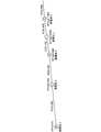
- FIG. 9 is a diagram showing an example of the connection relationship between each layer in the hierarchical logical network.
- a logical link connecting the same logical nodes in each layer is an inter-layer link.
- the boundaries of each hierarchy in a hierarchical logical network correspond to waypoints or attribute change points.
- the boundary between the layer 0 and the layer 1 corresponds to the waypoint 1
- the boundary between the layer 2 and the layer 3 corresponds to the attribute change point.
- Inter-layer links are set according to the concepts shown in (A) and (B) below.
- the matching unit 4 When the boundary between layers corresponds to a waypoint, the matching unit 4 satisfies only a logical node that can be regarded as having a correspondence relationship by satisfying a condition such as being within a predetermined distance from the waypoint. , Set inter-level links.
- the matching unit 4 When the boundary between layers corresponds to the attribute change point, the matching unit 4 unconditionally sets the inter-layer link for all logical nodes.
- the matching unit 4 sets the cost in the hierarchical logical network. Specifically, the matching unit 4 sets the cost for the inter-layer link set in step S23 and the logical link in each layer (hereinafter, also referred to as “intra-layer link”).
- the cost setting value is designed to be small when a route that matches the movement history of the moving body or a route that is close to the movement history of the moving body is selected. Further, the set value of the cost is designed to be large when a route that does not match the movement history of the moving body or a route far from the movement history of the moving body is selected.
- the above-mentioned "match” or “mismatch”, or “near” or “far” is quantitatively determined based on the coordinates of the waypoint and the attribute information of the movement history, and based on the result. Set the cost.
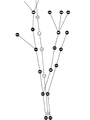
- FIG. 10 is a diagram showing an example of costs in a hierarchical logical network. The cost is set according to the concept shown in (C), (D), and (E) below.
- the matching unit 4 sets the cost according to the degree of matching between the link attribute included in the movement information corresponding to each layer and the link attribute of the physical link corresponding to the logical link. .. If the degree of agreement is large, the cost is reduced, and if the degree of agreement is small, the cost is increased.
- the matching unit 4 sets the cost of the logical link AB to "0".
- the matching unit 4 sets the cost of the logical link other than the logical link AB to "100".
- "logical link AB” indicates that it is a link connecting the logical node A and the logical node B, and the same applies to other logical links.
- the matching unit 4 within each layer is based on the traveling direction of the moving body at the branching point of each layer, the presence / absence of branching of the physical link corresponding to the logical link, and the traveling direction after the branching. You may set the cost of the logical link of. In this case, the traveling direction of the moving body is included in the moving information.
- the matching unit 4 determines the degree of coincidence between the coordinates of each waypoint and the coordinates of the physical link corresponding to the logical link. Set the cost. If the distance between the two coordinates is short, it is judged that the degree of coincidence is large and the cost is reduced, and if the distance between the two coordinates is long, the degree of coincidence is judged to be small and the cost is increased.
- the distance between the two coordinates may be the distance of a perpendicular line drawn from the coordinates of the waypoint with respect to the physical link. If a perpendicular line cannot be drawn from the coordinates of the waypoint to the physical link, it may be a straight line distance from the coordinates of the waypoint to the end point closer to the physical link.
- the matching unit 4 may set the cost according to the degree of coincidence between the coordinates of the waypoint and the coordinates of the physical node.
- step S25 the matching unit 4 searches for a route in the hierarchical logical network. Specifically, the matching unit 4 applies a Dijkstra method or the like to search for a route having the lowest cost in the cost set in step S24. At this time, the route search is performed not considering the physical network but only considering that the cost is minimized in the hierarchical logical network.
- FIG. 11 is a diagram showing the result of route search in the hierarchical logical network.
- the matching unit 4 searches for a route that has the lowest cost in the hierarchical logical network.
- FIG. 12 shows the result of reflecting the result of the route search on the physical network.
- the movement information includes a route composed of a plurality of links connecting the physical node A, the physical node B, the physical node C, the physical node D, the physical node E, and the physical node F.
- the route having the highest degree of coincidence with the route composed of the point sequence that is, the route searched or estimated by the route search unit 11 of IVI9).
- a hierarchical logical network is generated based on a coordinate point sequence included in a route in which the moving body travels or is predicted to travel in the future and a high-precision map, and the hierarchical logical network is used to generate a high level. Find the route on the precision map. This makes it possible to apply the state of the physical node to a given coordinate point sequence to the shortest path problem in the form of a "hierarchy".
- inter-layer links that connect the same logical nodes between layers are set, and costs are set for the inter-layer links. This makes it possible to set the cost according to the positional relationship between the coordinate point sequence and the physical link.
- the shortest route search is performed using the cost of inter-layer links, and the route on a high-precision map is obtained. This makes it possible to find a route that minimizes the cost of the entire route.
- the shortest route search may be performed using the costs of a plurality of parameters.
- Link attributes other than the link number may be used for the plurality of parameters, and each may be weighted. This makes it possible to obtain a route that considers a plurality of parameters.
- FIG. 13 is a block diagram showing an application example of the map matching device 1 according to the second embodiment, and shows an example of a system configuration including a server 18 and an information device 24.
- the information device 24 is an in-vehicle device that outputs probe data, and includes a gyro sensor 25, a GPS (Global Positioning System) receiver 26, a positioning unit 27, and a transmission unit 28.
- the information device 24 is provided on the moving body.
- the gyro sensor 25 detects the angular velocity of the moving body during traveling.
- the GPS receiver 26 calculates the position of the moving body based on the signal received from the GPS satellite.
- the positioning unit 27 is a moving body in a place where the GPS receiver 26 cannot receive a signal, such as in a tunnel, based on the angular velocity detected by the gyro sensor 25 and the position of the moving body calculated by the GPS receiver 26. Calculate the position of. In a place where the GPS receiver 26 can receive a signal, the position calculated by the GPS receiver may be used as it is, based on the signal received by the GPS receiver 26 and the angular velocity detected by the gyro sensor 25. The position of the moving body may be calculated.
- the transmission unit 28 transmits the position information of the moving body calculated by the positioning unit 27 and additional event information to the server 18 as movement information (probe data) via the Internet.
- the event information include information around the moving body acquired from a sensor (not shown) provided on the moving body, the state of the driver of the moving body, and the like.
- the server 18 is a probe data analysis server that analyzes movement information (probe data) received from the information device 24, and is a map matching device 1, a receiving unit 19, an event information storage unit 20, a map DB 21, and a matching history. It includes a storage unit 22 and a statistical processing unit 23.
- the map DB 21 stores the above-mentioned normal map will be described, but the above-mentioned high-precision map may be stored.
- the receiving unit 19 receives the movement information of the moving body from the information device 24 via the Internet.
- the event information is recorded in the event information storage unit 20, and the position information of the moving body is acquired and held by the movement information acquisition unit 3.
- the receiving unit 19 receives the moving information from each information device 24.
- the map matching device 1 includes a map information acquisition unit 2, a movement information acquisition unit 3, and a matching unit 4. Since the map information acquisition unit 2 and the matching unit 4 have the same configuration and operation as those described in the first embodiment, detailed description thereof will be omitted here.
- the movement information acquisition unit 3 acquires the position information of the moving body among the movement information received by the receiving unit 19 and holds it in chronological order. Further, when the movement information acquisition unit 3 acquires the position information of a plurality of moving bodies, the movement information acquisition unit 3 holds the position information for each moving body in chronological order. In this way, the movement information acquisition unit 3 acquires the coordinate point sequence of the position of the moving body on the route traveled in the past.
- the event information storage unit 20 stores event information in chronological order among the movement information received by the reception unit 19.
- the event information storage unit 20 stores the moving information for each moving body.
- the matching history storage unit 22 stores the link sequence included in the route on which the moving body has moved on the map, which is specified by the matching unit 4 of the map matching device 1.
- the matching history storage unit 22 stores the link sequence for each moving body.
- the statistical processing unit 23 links the link sequence stored in the matching history storage unit 22 and the event information stored in the event information storage unit 20 based on a common time (time stamp), and is included in the event information. Identify exactly which link on the map the event occurred on. That is, the statistical processing unit 23 accurately specifies the position of the moving body on the map when an event occurs.
- the map matching device 1 performs the same operation as that of the first embodiment, so that the route on which the moving body has traveled in the past can be accurately matched on the map. It becomes.
- the map matching device 1 includes a processing circuit for acquiring map information, acquiring movement information of a moving body, and identifying a link sequence corresponding to a route on a map based on the map information and the movement information.
- the processing circuit may be dedicated hardware, and is a processor (CPU (Central Processing Unit), a central processing unit, a processing unit, an arithmetic unit, a microprocessor, a microcomputer, a DSP) that executes a program stored in a memory. It may also be called a Digital Signal Processor).
- the processing circuit 29 may be, for example, a single circuit, a composite circuit, a programmed processor, a parallel programmed processor, or an ASIC (Application Specific Integrated Circuit). , FPGA (Field Programmable Gate Array), or a combination of these.
- Each function of the map information acquisition unit 2, the movement information acquisition unit 3, and the matching unit 4 may be realized by the processing circuit 29, or each function may be collectively expressed by one processing circuit 29.
- each function of the map information acquisition unit 2, the movement information acquisition unit 3, and the matching unit 4 is realized by software, firmware, or a combination of software and firmware. ..
- the software or firmware is described as a program and stored in the memory 31.
- the processor 30 realizes each function by reading and executing the program recorded in the memory 31. That is, as a result, the map matching device 1 has a step of acquiring map information, a step of acquiring movement information of a moving body, and a step of identifying a link sequence corresponding to a route on a map based on the map information and movement information.
- a memory 31 for storing a program to be executed is provided.
- the memory is, for example, non-volatile or volatile such as RAM (RandomAccessMemory), ROM (ReadOnlyMemory), flash memory, EPROM (ErasableProgrammableReadOnlyMemory) and EEPROM (Electrically ErasableProgrammableReadOnlyMemory). It may be a semiconductor memory, a magnetic disk, a flexible disk, an optical disk, a compact disk, a DVD (Digital Versatile Disc), or any other storage medium that will be used in the future.
- the movement information acquisition unit 3 and the matching unit 4 For each function of the map information acquisition unit 2, the movement information acquisition unit 3, and the matching unit 4, some functions may be realized by dedicated hardware and other functions may be realized by software or firmware. good.
- the processing circuit can realize each of the above-mentioned functions by hardware, software, firmware, or a combination thereof.
- the map matching device described above can be applied to a high-precision locator as described in the first embodiment, or can be applied to a probe data analysis server as described in the second embodiment. It is not limited to.
- the map matching device can be applied to, for example, an in-vehicle navigation device, that is, a car navigation device, or a PND (Portable Navigation Device) that can be mounted on a vehicle, and these can be appropriately combined to be constructed as a system. can.
- each function or each component of the map matching device is distributed and arranged in each function for constructing the system.
- the software according to the above embodiment may be incorporated into, for example, a server.
- the map matching method realized by the server executing this software acquires map information including the link endpoint coordinates, which are the coordinates of the endpoints of a plurality of links, and the connection relationship of each link, and follows a predetermined route. Acquiring the movement information of a moving object, identifying the link column which is a column of links corresponding to the route based on the acquired map information and the acquired movement information, and specifying the link column is the connection information.
- a physical network which is a road network based on movement information, is generated, a plurality of the physical networks are duplicated to generate a hierarchical logical network configured in a hierarchical manner, and the route with the lowest cost in the hierarchical logical network is used as a link sequence. Including identifying.
- each embodiment can be freely combined, and each embodiment can be appropriately modified or omitted.
- Map matching device 2 Map information acquisition unit, 3 Movement information acquisition unit, 4 Matching unit, 5 High-precision locator, 6 Receiver unit, 7 High-precision map DB, 8 Transmission unit, 9 IVI, 10 IVI map DB, 11 Route search unit, 12 transmission unit, 13 ECU, 14 reception unit, 15 recognition unit, 16 judgment unit, 17 control unit, 18 server, 19 reception unit, 20 event information storage unit, 21 map DB, 22 matching history storage unit, 23 statistical processing unit, 24 information equipment, 25 gyro sensor, 26 GPS receiver, 27 positioning unit, 28 transmission unit, 29 processing circuit, 30 processor, 31 memory.
Landscapes
- Engineering & Computer Science (AREA)
- Radar, Positioning & Navigation (AREA)
- Remote Sensing (AREA)
- Automation & Control Theory (AREA)
- Physics & Mathematics (AREA)
- General Physics & Mathematics (AREA)
- Databases & Information Systems (AREA)
- Navigation (AREA)
- Devices That Are Associated With Refrigeration Equipment (AREA)
- Instructional Devices (AREA)
Priority Applications (4)
| Application Number | Priority Date | Filing Date | Title |
|---|---|---|---|
| JP2022508570A JP7076665B2 (ja) | 2020-03-24 | 2020-03-24 | マップマッチング装置およびマップマッチング方法 |
| PCT/JP2020/013078 WO2021192054A1 (ja) | 2020-03-24 | 2020-03-24 | マップマッチング装置およびマップマッチング方法 |
| US17/796,417 US12222207B2 (en) | 2020-03-24 | 2020-03-24 | Map matching apparatus and map matching method |
| DE112020006473.5T DE112020006473B4 (de) | 2020-03-24 | 2020-03-24 | Kartenabgleichsvorrichtung und Kartenabgleichsverfahren |
Applications Claiming Priority (1)
| Application Number | Priority Date | Filing Date | Title |
|---|---|---|---|
| PCT/JP2020/013078 WO2021192054A1 (ja) | 2020-03-24 | 2020-03-24 | マップマッチング装置およびマップマッチング方法 |
Publications (1)
| Publication Number | Publication Date |
|---|---|
| WO2021192054A1 true WO2021192054A1 (ja) | 2021-09-30 |
Family
ID=77891221
Family Applications (1)
| Application Number | Title | Priority Date | Filing Date |
|---|---|---|---|
| PCT/JP2020/013078 Ceased WO2021192054A1 (ja) | 2020-03-24 | 2020-03-24 | マップマッチング装置およびマップマッチング方法 |
Country Status (4)
| Country | Link |
|---|---|
| US (1) | US12222207B2 (https=) |
| JP (1) | JP7076665B2 (https=) |
| DE (1) | DE112020006473B4 (https=) |
| WO (1) | WO2021192054A1 (https=) |
Cited By (2)
| Publication number | Priority date | Publication date | Assignee | Title |
|---|---|---|---|---|
| JPWO2024095368A1 (https=) * | 2022-11-01 | 2024-05-10 | ||
| JP2025510162A (ja) * | 2022-03-25 | 2025-04-14 | メルセデス・ベンツ グループ アクチェンゲゼルシャフト | 車両の自動走行動作のためのナビゲーションルートを決定する方法 |
Families Citing this family (1)
| Publication number | Priority date | Publication date | Assignee | Title |
|---|---|---|---|---|
| CN115046559A (zh) * | 2022-06-13 | 2022-09-13 | 阿波罗智联(北京)科技有限公司 | 信息处理方法和装置 |
Citations (3)
| Publication number | Priority date | Publication date | Assignee | Title |
|---|---|---|---|---|
| JP2004125537A (ja) * | 2002-09-30 | 2004-04-22 | Matsushita Electric Ind Co Ltd | マップマッチング方法と装置 |
| JP2004354395A (ja) * | 2004-09-09 | 2004-12-16 | Matsushita Electric Ind Co Ltd | マップマッチング方法と装置 |
| JP5587306B2 (ja) * | 2008-06-30 | 2014-09-10 | トムトム インターナショナル ベスローテン フエンノートシャップ | 位置を表す符号化データから位置を解決する方法 |
Family Cites Families (8)
| Publication number | Priority date | Publication date | Assignee | Title |
|---|---|---|---|---|
| DE112007003769B4 (de) * | 2006-10-18 | 2015-10-15 | Mitsubishi Electric Corp. | Karteninformations-Verarbeitungsvorrichtung |
| JP5977753B2 (ja) * | 2011-10-17 | 2016-08-24 | クラリオン株式会社 | 経路探索方法及び経路探索装置 |
| WO2015107856A1 (ja) | 2014-01-14 | 2015-07-23 | クラリオン株式会社 | 経路探索装置 |
| WO2016048143A1 (en) | 2014-09-22 | 2016-03-31 | Wolting Holding B.V. | Compiler for and method of software defined networking, storage and compute determining physical and virtual resources |
| WO2019032568A1 (en) * | 2017-08-11 | 2019-02-14 | Cummins Inc. | ROUTE PARAMETER MANAGER SYSTEM |
| JP7173748B2 (ja) | 2018-04-13 | 2022-11-16 | 日立Astemo株式会社 | 経路生成装置、及び自動運転システム |
| DE112019004232T5 (de) * | 2018-08-24 | 2021-06-10 | Sumitomo Electric Industries, Ltd. | Informationsbereitstellungsvorrichtung, Informationsbereitstellungsverfahren, Informationsbereitstellungssystem, Computerprogramm, und Datenstruktur |
| US11200431B2 (en) * | 2019-05-14 | 2021-12-14 | Here Global B.V. | Method and apparatus for providing lane connectivity data for an intersection |
-
2020
- 2020-03-24 WO PCT/JP2020/013078 patent/WO2021192054A1/ja not_active Ceased
- 2020-03-24 DE DE112020006473.5T patent/DE112020006473B4/de active Active
- 2020-03-24 US US17/796,417 patent/US12222207B2/en active Active
- 2020-03-24 JP JP2022508570A patent/JP7076665B2/ja active Active
Patent Citations (3)
| Publication number | Priority date | Publication date | Assignee | Title |
|---|---|---|---|---|
| JP2004125537A (ja) * | 2002-09-30 | 2004-04-22 | Matsushita Electric Ind Co Ltd | マップマッチング方法と装置 |
| JP2004354395A (ja) * | 2004-09-09 | 2004-12-16 | Matsushita Electric Ind Co Ltd | マップマッチング方法と装置 |
| JP5587306B2 (ja) * | 2008-06-30 | 2014-09-10 | トムトム インターナショナル ベスローテン フエンノートシャップ | 位置を表す符号化データから位置を解決する方法 |
Cited By (5)
| Publication number | Priority date | Publication date | Assignee | Title |
|---|---|---|---|---|
| JP2025510162A (ja) * | 2022-03-25 | 2025-04-14 | メルセデス・ベンツ グループ アクチェンゲゼルシャフト | 車両の自動走行動作のためのナビゲーションルートを決定する方法 |
| JP7818717B2 (ja) | 2022-03-25 | 2026-02-20 | メルセデス・ベンツ グループ アクチェンゲゼルシャフト | 車両の自動走行動作のためのナビゲーションルートを決定する方法 |
| JPWO2024095368A1 (https=) * | 2022-11-01 | 2024-05-10 | ||
| WO2024095368A1 (ja) * | 2022-11-01 | 2024-05-10 | 三菱電機株式会社 | 経路情報作成装置および経路情報作成方法 |
| JP7649091B2 (ja) | 2022-11-01 | 2025-03-19 | 三菱電機モビリティ株式会社 | 経路情報作成装置および経路情報作成方法 |
Also Published As
| Publication number | Publication date |
|---|---|
| DE112020006473B4 (de) | 2024-02-01 |
| DE112020006473T5 (de) | 2022-10-20 |
| US20230049449A1 (en) | 2023-02-16 |
| US12222207B2 (en) | 2025-02-11 |
| JPWO2021192054A1 (https=) | 2021-09-30 |
| JP7076665B2 (ja) | 2022-05-27 |
Similar Documents
| Publication | Publication Date | Title |
|---|---|---|
| US11125569B2 (en) | Midpoint-based map-agnostic navigation routing | |
| US8825364B2 (en) | Vehicle position recognition device and vehicle position recognition program | |
| US10151592B2 (en) | Map matching quality evaluation | |
| EP3109591B1 (en) | Decision-based map-agnostic navigation routing | |
| US9494694B1 (en) | Method and apparatus of road location inference for moving object | |
| CN113721599B (zh) | 定位方法和定位装置 | |
| CN109997015B (zh) | 用于指引路线的装置、方法、计算机程序以及计算机可读记录介质 | |
| JP7076665B2 (ja) | マップマッチング装置およびマップマッチング方法 | |
| US10145691B2 (en) | Ambiguity map match rating | |
| EP3789886B1 (en) | Method, apparatus, and computer program product for generating correspondence between map versions | |
| EP3789732B1 (en) | Method, apparatus, and computer program product for generating correspondence between map versions | |
| US20180120115A1 (en) | Mobile-body position detecting apparatus and mobile-body position detecting method | |
| JP5990018B2 (ja) | ナビゲーション装置、情報提供方法及びプログラム | |
| EP3748302B1 (en) | Method, apparatus, and computer program product for map data agnostic route fingerprints | |
| CN111400418A (zh) | 车道的定位方法、装置、车辆、存储介质及地图构建方法 | |
| US11933618B2 (en) | Determining a route on a map through trace matching with a corresponding route on another map | |
| CN109313034B (zh) | 行驶控制系统 | |
| CN116184459B (zh) | 一种定位信号补偿方法、系统、电子设备和可读存储介质 | |
| CN111630348B (zh) | 地理地图的更新 | |
| WO2023127003A1 (ja) | 運転支援策定装置および運転支援策定方法 | |
| KR102360470B1 (ko) | 회전코스트를 반영한 도착예정시간 산출 장치 및 방법 | |
| JP2023023719A (ja) | 情報処理装置 | |
| US20210239475A1 (en) | Evaluation of a route determination | |
| WO2026023002A1 (ja) | 運転支援策定装置、運転支援策定システム、および運転支援策定方法 | |
| JP2024118234A (ja) | 情報処理方法及び情報処理装置 |
Legal Events
| Date | Code | Title | Description |
|---|---|---|---|
| 121 | Ep: the epo has been informed by wipo that ep was designated in this application |
Ref document number: 20926975 Country of ref document: EP Kind code of ref document: A1 |
|
| ENP | Entry into the national phase |
Ref document number: 2022508570 Country of ref document: JP Kind code of ref document: A |
|
| 122 | Ep: pct application non-entry in european phase |
Ref document number: 20926975 Country of ref document: EP Kind code of ref document: A1 |