WO2021192054A1 - マップマッチング装置およびマップマッチング方法 - Google Patents
マップマッチング装置およびマップマッチング方法 Download PDFInfo
- Publication number
- WO2021192054A1 WO2021192054A1 PCT/JP2020/013078 JP2020013078W WO2021192054A1 WO 2021192054 A1 WO2021192054 A1 WO 2021192054A1 JP 2020013078 W JP2020013078 W JP 2020013078W WO 2021192054 A1 WO2021192054 A1 WO 2021192054A1
- Authority
- WO
- WIPO (PCT)
- Prior art keywords
- link
- map
- route
- movement information
- hierarchical
- Prior art date
Links
Images


Classifications
-
- G—PHYSICS
- G01—MEASURING; TESTING
- G01C—MEASURING DISTANCES, LEVELS OR BEARINGS; SURVEYING; NAVIGATION; GYROSCOPIC INSTRUMENTS; PHOTOGRAMMETRY OR VIDEOGRAMMETRY
- G01C21/00—Navigation; Navigational instruments not provided for in groups G01C1/00 - G01C19/00
- G01C21/26—Navigation; Navigational instruments not provided for in groups G01C1/00 - G01C19/00 specially adapted for navigation in a road network
- G01C21/28—Navigation; Navigational instruments not provided for in groups G01C1/00 - G01C19/00 specially adapted for navigation in a road network with correlation of data from several navigational instruments
- G01C21/30—Map- or contour-matching
- G01C21/32—Structuring or formatting of map data
-
- G—PHYSICS
- G01—MEASURING; TESTING
- G01C—MEASURING DISTANCES, LEVELS OR BEARINGS; SURVEYING; NAVIGATION; GYROSCOPIC INSTRUMENTS; PHOTOGRAMMETRY OR VIDEOGRAMMETRY
- G01C21/00—Navigation; Navigational instruments not provided for in groups G01C1/00 - G01C19/00
- G01C21/26—Navigation; Navigational instruments not provided for in groups G01C1/00 - G01C19/00 specially adapted for navigation in a road network
- G01C21/28—Navigation; Navigational instruments not provided for in groups G01C1/00 - G01C19/00 specially adapted for navigation in a road network with correlation of data from several navigational instruments
- G01C21/30—Map- or contour-matching
-
- G—PHYSICS
- G01—MEASURING; TESTING
- G01C—MEASURING DISTANCES, LEVELS OR BEARINGS; SURVEYING; NAVIGATION; GYROSCOPIC INSTRUMENTS; PHOTOGRAMMETRY OR VIDEOGRAMMETRY
- G01C21/00—Navigation; Navigational instruments not provided for in groups G01C1/00 - G01C19/00
- G01C21/38—Electronic maps specially adapted for navigation; Updating thereof
- G01C21/3804—Creation or updating of map data
- G01C21/3807—Creation or updating of map data characterised by the type of data
- G01C21/3815—Road data
-
- G—PHYSICS
- G01—MEASURING; TESTING
- G01C—MEASURING DISTANCES, LEVELS OR BEARINGS; SURVEYING; NAVIGATION; GYROSCOPIC INSTRUMENTS; PHOTOGRAMMETRY OR VIDEOGRAMMETRY
- G01C21/00—Navigation; Navigational instruments not provided for in groups G01C1/00 - G01C19/00
- G01C21/38—Electronic maps specially adapted for navigation; Updating thereof
- G01C21/3804—Creation or updating of map data
- G01C21/3833—Creation or updating of map data characterised by the source of data
- G01C21/3841—Data obtained from two or more sources, e.g. probe vehicles
-
- G—PHYSICS
- G01—MEASURING; TESTING
- G01C—MEASURING DISTANCES, LEVELS OR BEARINGS; SURVEYING; NAVIGATION; GYROSCOPIC INSTRUMENTS; PHOTOGRAMMETRY OR VIDEOGRAMMETRY
- G01C21/00—Navigation; Navigational instruments not provided for in groups G01C1/00 - G01C19/00
- G01C21/38—Electronic maps specially adapted for navigation; Updating thereof
- G01C21/3863—Structures of map data
- G01C21/387—Organisation of map data, e.g. version management or database structures
- G01C21/3878—Hierarchical structures, e.g. layering
Definitions
- the present disclosure relates to a map matching device and a map matching method for expressing the movement route of a moving body before conversion on the converted map between different maps.
- a high-precision locator provides high-precision lane-level shape information (latitude and longitude) contained in a high-precision map for a route represented at the road level on which the vehicle should or will travel and its surroundings. Information such as (and curvature, etc.), road attributes (road type, etc.), link attributes (acceleration / deceleration lanes, ramp lanes, and branch lanes, etc.), speed limits, and whether or not lanes can be changed, along with highly accurate vehicle position information.
- the ECU Electronic Control Unit
- the high-precision locator acquires the route expressed at the road level where the vehicle should or is going to travel from the IVI (In-Vehicle Infotainment) provided by the vehicle.
- IVI includes, for example, a navigation system.
- map used by IVI and the high-precision map used by the high-precision locator have different map suppliers, but even if they are the same map supplier, the maintenance standards and digitization of each map Since the methods are different, both maps are not linked on a link-by-link basis. Therefore, in the high-precision locator, it is necessary to convert the route based on the map used in IVI in order to represent it on the high-precision map that it holds.
- Information that can be commonly used in both maps at the time of conversion includes, for example, latitude / longitude information and some attribute information.
- Some attribute information includes, for example, infrastructure link number (VICS (Vehicle Information and Communication System, registered trademark) link number and TMC (Traffic Message Channel) link number, etc.), road type, link type, link direction, branch direction, etc. , Number of lanes, road width, road name, national road number, and prefecture number.
- VICS Vehicle Information and Communication System, registered trademark
- TMC Traffic Message Channel
- offline map matching refers to an offline version (post-processing version) of so-called “map matching”.
- Map matching generally refers to the process of identifying a traveling link on a map based on information such as latitude and longitude calculated by satellite positioning or inertial navigation while the locator is traveling on a moving object. Since such processing requires real-time performance, it is common for locators to perform processing to identify the most probable traveling link at that time based on information such as latitude and longitude that are sequentially input. be.
- offline map matching information such as multiple latitudes and longitudes included in the entire route from the start of running to the end of running is collectively input to the locator.
- offline map matching the process of identifying the most probable travel link based on the consistency of the entire route and the continuity of the travel link sequence is performed, so matching skipping and erroneous matching that occur in general map matching are performed. The problem can be suppressed. Therefore, it is expected that offline map matching will be possible in principle to identify the driving link that is considered to be the most accurate and most probable than general map matching.
- OpenLR etc. as a technology aimed at converting different map information.
- OpenLR is disclosed in, for example, Patent Document 1 and Non-Patent Document 1.
- the encoding side encodes the data using the map that the encoding side has so that the decoding side is expected to decode correctly.
- the received data is decoded using the map that the decoder side has.
- a position reference point LRP that can correctly decode the route is specified, and the position reference point and the attribute information related to the position reference point are transmitted to the decoding side. ..
- OpenLR identifies the link that best matches the position reference point in the input route information and its attribute information among the links connected to the position reference point, and it is an absolute condition to pass through the link. It is an algorithm that searches for the shortest path between position reference points. Therefore, if there is an error in identifying the position reference point and the link that best matches the attribute information, there is a problem that the correct route cannot be shown on the converted map. That is, it is understood that this is an adverse effect of identifying the via link by using the local evaluation function in the route, instead of evaluating the degree of matching of the input route information by looking at the entire route. This is an essential problem in the OpenLR algorithm in improving the conversion rate of route information between different maps.
- OpenLR it is necessary to perform the encoding process specified by the standard on the encoding side. Therefore, when the route information is transmitted to the decoding side in a format such as ADASIS (Advanced Driver Assistance Systems Interface Specification) -V2, which is a standard forward route output format, the decoding side performs the decoding process as it is for the received route information. There is a problem that it cannot be applied.
- ADASIS Advanced Driver Assistance Systems Interface Specification
- the present disclosure has been made to solve such a problem, and provides a map matching device and a map matching method capable of accurately matching a route before conversion between different maps on a map after conversion.
- the purpose is to provide.
- the map matching device includes a map information acquisition unit that acquires map information including the link endpoint coordinates, which are the coordinates of the endpoints of a plurality of links, and the connection relationship of each link, and a map information acquisition unit in advance.
- the link corresponding to the route A matching unit that specifies a link column, which is a column, is provided, and the matching unit generates a physical network that is a road network based on a connection relationship and movement information, and a plurality of the physical networks are duplicated to form a hierarchical structure.
- a type logical network is generated, and the link column having the lowest cost in the hierarchical logical network is specified.
- the matching unit in the map matching device, the matching unit generates a physical network which is a road network based on the connection relationship and the movement information, and a plurality of the physical networks are duplicated to form a hierarchical logical network configured in a hierarchical manner. Since the link sequence that is generated and has the lowest cost in the hierarchical logical network is specified, it is possible to accurately match the route before conversion on the map after conversion between different maps.
- FIG. It is a block diagram which shows an example of the structure of the map matching apparatus by Embodiment 1.
- FIG. It is a block diagram which shows the application example of the map matching apparatus by Embodiment 1.
- FIG. It is a flowchart which shows an example of the operation of the map matching apparatus by Embodiment 1.
- FIG. It is a flowchart which shows an example of the operation of the map matching apparatus by Embodiment 1.
- FIG. It is a figure which shows an example of the movement information by Embodiment 1.
- FIG. It is a figure which shows an example of the hierarchical list by Embodiment 1.
- FIG. It is a figure which shows an example of the physical network by Embodiment 1.
- FIG. It is a figure which shows the movement information and the physical network by Embodiment 1.
- FIG. It is a figure which shows an example of the connection relation between each layer in the hierarchical logical network by Embodiment 1.
- FIG. It is a figure which shows an example of the cost in the hierarchical logical network by Embodiment 1.
- FIG. It is a figure which shows an example of the result of the route search in the hierarchical logical network by Embodiment 1.
- FIG. It is a figure which shows an example of the result of the route search in the physical network by Embodiment 1.
- FIG. It is a block diagram which shows the application example of the map matching apparatus by Embodiment 2.
- FIG. It is a block diagram which shows an example of the hardware composition of the map matching apparatus by embodiment. It is a block diagram which shows an example of the hardware composition of the map matching apparatus by embodiment.
- FIG. 1 is a block diagram showing an example of the configuration of the map matching device 1 according to the first embodiment.
- the map matching device 1 performs the offline map matching described above.
- the map matching device 1 includes a map information acquisition unit 2, a movement information acquisition unit 3, and a matching unit 4.
- the map information acquisition unit 2 acquires map information including the link endpoint coordinates, which are the coordinates of the endpoints of each link, and the connection relationship of each link.
- the movement information acquisition unit 3 acquires movement information of a moving body on a predetermined route. In the following, the moving body will be described as being a vehicle.
- the matching unit 4 specifies a link sequence, which is a sequence of links corresponding to the route, based on the map information acquired by the map information acquisition unit 2 and the movement information acquired by the movement information acquisition unit 3. Specifically, the matching unit 4 generates a physical network that is a road network based on the connection relationship between the movement information and the links included in the map information, duplicates the physical network in a plurality of layers, and stacks the physical networks in a hierarchical manner. Generate a typed logical network and identify the link sequence with the lowest cost in the hierarchical logical network.
- FIG. 2 is a block diagram showing an application example of the map matching device 1 shown in FIG. 1, and shows an example of the configuration of an automatic driving system.
- the map matching device 1 identifies the route of the moving body acquired from IVI9 on the high-precision map and transmits it to the ECU 13.
- the ECU 13 controls to automatically drive the moving body according to the route specified on the high-precision map.
- ADAS Advanced Driver Assistance System
- the high-precision locator 5 includes a map matching device 1, a receiving unit 6, a high-precision map DB (database) 7, and a transmitting unit 8.
- the map matching device 1 includes a map information acquisition unit 2, a movement information acquisition unit 3, and a matching unit 4.
- the functions of the map information acquisition unit 2, the movement information acquisition unit 3, and the matching unit 4 are as described above.
- the map information acquisition unit 2 acquires map information, which is a high-precision map, from the high-precision map DB (database) 7.
- the map information acquisition unit 2 is an API (Application Programming Interface) group for acquiring necessary information from the high-precision map DB 7.
- the movement information acquisition unit 3 acquires the movement information received from the IVI 9 by the reception unit 6.
- the movement information includes a sequence of coordinate points of positions on the route on which the moving body is to travel. Further, the movement information may include attribute information regarding the route. Examples of the route on which the moving body is scheduled to travel include a route being guided, or a route that is predicted to travel in the future if the moving body is not being guided.
- the matching unit 4 specifies a link sequence, which is a sequence of links corresponding to the route, based on the map information acquired by the map information acquisition unit 2 and the movement information acquired by the movement information acquisition unit 3. If the map information corresponding to a part of the route included in the movement information is not stored in the high-precision map DB 7, the matching unit 4 does not specify the link sequence corresponding to the part of the section.
- the receiving unit 6 receives the movement information on the route on which the moving body is scheduled to travel from the IVI 9.
- the high-precision map DB7 stores the high-precision map as a database. Specifically, the high-precision map DB 7 stores detailed shape information at the lane level, information indicating the connection relationship between lanes, lane changeability information, and the like.
- the transmission unit 8 adds road information (position, shape, attributes, etc.) necessary for control by the ECU 13 and position information of a moving body to the link sequence specified by the matching unit 4 and transmits the link sequence to the ECU 13. .
- the position information of the moving body the position information measured by the high-precision positioning unit (not shown) provided in the high-precision locator 5 may be used, and the high-precision locator 5 is the position of the moving body based on the movement information received by the receiving unit 6. You may guess.
- IVI9 includes an IVI map DB (database) 10, a route search unit 11, and a transmission unit 12.
- IVI9 is, for example, a navigation system.
- the IVI map DB10 stores a normal map used in the navigation system as a database.
- a typical map does not include detailed lane-level shapes, only road-level schematic shapes. This schematic shape is less accurate than a high-precision map. Generally, it is said that the rough shape at the road level may include an error of about 10 m.
- the latitude and longitude of branch points in the normal map may differ from the high-precision map due to the difference in maintenance specifications between the normal map and the high-precision map.
- ordinary maps do not always include newly opened roads in synchronization with high-precision maps, and it is assumed that there are differences in the contents of both maps.
- the route search unit 11 determines the route to the destination at the road level as the shortest route problem based on the normal map stored in the IVI map DB 10. That is, the route search unit 11 determines the route on which the moving body will travel in the future.
- the transmission unit 12 transmits the movement information of the moving body on the route searched by the route search unit 11 to the high-precision locator 5. If the destination is not set, the transmission unit 12 transmits the route predicted that the moving body will travel in the future to the high-precision locator 5.
- the route search unit 11 may perform such a route prediction.
- a standard standard such as ADASIS-V2 may be used for communication between the transmission unit 12 and the reception unit 6 of the high-precision locator 5.
- the ECU 13 includes a receiving unit 14, a recognition unit 15, a determination unit 16, and a control unit 17.
- the ECU 13 controls the automatic operation of the moving body.
- the receiving unit 14 receives information such as a link sequence specified on the high-precision map from the high-precision locator 5.
- the cognitive unit 15 recognizes the state of the moving body and the situation around the moving body, which are necessary for automatic driving, based on the information received from the sensor provided on the moving body.
- the determination unit 16 determines how the movement of the moving body should be controlled based on the recognition result by the recognition unit 15 and the information received by the reception unit 14.
- the control unit 17 controls the movement of the moving body based on the determination result by the determination unit 16 and the information received by the reception unit 14.
- FIG. 3 is a flowchart showing an example of the operation of the map matching device 1.
- step S11 the map information acquisition unit 2 acquires high-precision map information from the high-precision map DB 7.
- the movement information acquisition unit 3 acquires the movement information received from the IVI 9 by the reception unit 6.
- the matching unit 4 performs map matching processing.
- FIG. 4 is a flowchart showing the details of the map matching process in step S13 of FIG.
- step S21 the matching unit 4 generates a hierarchical list based on the coordinate point sequence and the attribute information included in the movement information acquired by the movement information acquisition unit 3.
- the movement information acquisition unit 3 acquires the movement information shown in FIG. 5.
- points 0, 1, 2, 3 indicate a sequence of coordinate points at a plurality of positions on the route on which the moving body is scheduled to travel.
- points 0, 1, 2, 3 are also collectively referred to as "waypoints”.
- Offset 0,500,900,1200,1500” indicates the distance from point 0.
- an unnumbered point existing between points 2 and 3 indicates a point at which the link attribute changes, and is also referred to as an “attribute change point”.
- the matching unit 4 generates a hierarchical list as shown in FIG. 6 based on the movement information shown in FIG.
- the hierarchical list shows a hierarchy in which movement information is arranged in Offset order and separated by waypoints and attribute change points.
- the matching unit 4 generates a physical network based on the movement information and the high-precision map.
- the physical network is a road network on a high-precision map that is a target when searching for a route on which a moving object is scheduled to travel on the high-precision map.
- the links and nodes that make up the physical network are referred to as "physical links” and “physical nodes,” respectively.
- the physical network has information about the physical link and the physical node, such as a link shape, a link attribute, a link number, and parameters necessary for cost calculation described later.
- the term “physical” is used here to clarify the contrast with the non-existent virtual "logical network", "logical link”, and “logical node” described later.
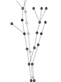
- the matching unit 4 searches for a physical link existing near a waypoint or an attribute change point. Then, the matching unit 4 develops the physical link from the searched physical link to the next waypoint or attribute change point. The matching unit 4 generates a physical network as shown in FIG. 7 by performing such a procedure for all waypoints and attribute change points.
- FIG. 8 is a diagram showing the movement information shown in FIG. 5 and the physical network shown in FIG. 7 together.
- the matching unit 4 searches for the physical link AB and the physical link HI existing near the point 0, which is a waypoint.
- the "physical link AB" indicates that the link connects the physical node A and the physical node B, and the same applies to other physical links.
- the matching unit 4 develops each of the physical link AB and the physical link HI up to the next waypoint, point 1.
- the physical link BC and the physical link BJ are expanded from the physical link AB
- the physical link IO is expanded from the physical link HI.
- the matching unit 4 creates a physical network by performing such a procedure for all waypoints and attribute change points.
- step S23 the matching unit 4 creates a hierarchical logical network and sets the connection relationship between the layers. Specifically, the matching unit 4 duplicates the physical network generated in step S22 by the same number as the number of layers shown in the layer list generated in step S21.
- a network in which a plurality of physical networks are duplicated and configured in a hierarchical manner is referred to as a "hierarchical logical network" in order to clarify the contrast with the above-mentioned "physical network” (FIG. 9 described later). reference).
- the links and nodes that make up the hierarchical logical network are referred to as "logical links” and “logical nodes”, respectively, in order to clarify the contrast with the above-mentioned “physical links” and “physical nodes”, respectively.
- the hierarchical logical network is a duplicate of the physical network, the physical link and the logical link having the same link attribute correspond to each other, and the physical node and the logical node having the same position coordinates correspond to each other. ..
- the logical node of the layer k (layers 0, 1, ... And the passing state of each way point is a state in which the way point k has already passed and the way point k + 1 and later have not passed.
- the movement of the logical node which is the physical node X and is from the layer k to the layer k + 1 corresponds to "determining that the waypoint k has been passed".
- the position of the physical node X is far away from the waypoint k, it is determined that the reproducibility of the route is low, and such a route is obtained. A big penalty is imposed on.
- the position of the physical node X is close to the waypoint k, it is determined that the reproducibility of the route is high, and a small penalty is imposed on such a route.
- the start link in the hierarchical logical network is the logical link in the hierarchy corresponding to the first waypoint and closest to the first waypoint.
- the end link in a hierarchical logical network is the logical link within the hierarchy corresponding to the last waypoint and closest to the last waypoint.
- the matching unit 4 determines that a logical link existing within a predetermined radius centered on the first waypoint is a start link, and within a predetermined radius centered on the last waypoint.
- the existing logical link is determined to be the end link.
- the start link and the end link include logical links connected back and forth based on the connection relationship of the links by a predetermined distance from the logical link. May be good.
- the number of layers in the hierarchical logical network corresponds to the number of division sections obtained by dividing the route searched by the route search unit 11 of IVI9 by waypoints and attribute change points has been described.
- the number of layers in the hierarchical logical network may correspond to the number of divided sections in which the route searched by the route search unit 11 of IVI9 is divided by the road attribute included in the movement information.
- road attributes include road type, link type, number of lanes, road width, speed limit, presence / absence of toll, link number, road name, national road number, and prefectural road number.
- the logical node of the hierarchy k and the physical link Y in the hierarchical logical network states that "the position of the physical moving body is the position of the physical link Y". And the road attribute in the movement history of the moving body is staying in the kth section ". Therefore, it is a physical link Y, and the movement of the logical node from the layer k to the layer k + 1 corresponds to "it is determined that the k-th and k + 1-th attribute change points in the movement history of the moving body have been passed.” ..
- the link attribute of the physical link Y does not match the kth road attribute of the moving body's movement history (when it is far away), It is judged that the reproducibility of the route is low, and a large penalty is imposed on such a route.
- the link attribute of the physical link Y matches (or is close to) the kth road attribute of the movement history of the moving object, it is determined that the route is highly reproducible, and a small penalty is given for such a route. Imposing.
- the hierarchy in the hierarchical logical network may be associated with both each waypoint and each road attribute in the movement history of the moving body.
- the matching unit 4 sets an inter-layer link at an appropriate position between the layers of the hierarchical logical network. Specifically, the matching unit 4 sets a logical link connecting the same logical nodes in each adjacent layer as an inter-layer link.
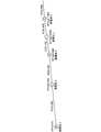
- FIG. 9 is a diagram showing an example of the connection relationship between each layer in the hierarchical logical network.
- a logical link connecting the same logical nodes in each layer is an inter-layer link.
- the boundaries of each hierarchy in a hierarchical logical network correspond to waypoints or attribute change points.
- the boundary between the layer 0 and the layer 1 corresponds to the waypoint 1
- the boundary between the layer 2 and the layer 3 corresponds to the attribute change point.
- Inter-layer links are set according to the concepts shown in (A) and (B) below.
- the matching unit 4 When the boundary between layers corresponds to a waypoint, the matching unit 4 satisfies only a logical node that can be regarded as having a correspondence relationship by satisfying a condition such as being within a predetermined distance from the waypoint. , Set inter-level links.
- the matching unit 4 When the boundary between layers corresponds to the attribute change point, the matching unit 4 unconditionally sets the inter-layer link for all logical nodes.
- the matching unit 4 sets the cost in the hierarchical logical network. Specifically, the matching unit 4 sets the cost for the inter-layer link set in step S23 and the logical link in each layer (hereinafter, also referred to as “intra-layer link”).
- the cost setting value is designed to be small when a route that matches the movement history of the moving body or a route that is close to the movement history of the moving body is selected. Further, the set value of the cost is designed to be large when a route that does not match the movement history of the moving body or a route far from the movement history of the moving body is selected.
- the above-mentioned "match” or “mismatch”, or “near” or “far” is quantitatively determined based on the coordinates of the waypoint and the attribute information of the movement history, and based on the result. Set the cost.
- FIG. 10 is a diagram showing an example of costs in a hierarchical logical network. The cost is set according to the concept shown in (C), (D), and (E) below.
- the matching unit 4 sets the cost according to the degree of matching between the link attribute included in the movement information corresponding to each layer and the link attribute of the physical link corresponding to the logical link. .. If the degree of agreement is large, the cost is reduced, and if the degree of agreement is small, the cost is increased.
- the matching unit 4 sets the cost of the logical link AB to "0".
- the matching unit 4 sets the cost of the logical link other than the logical link AB to "100".
- "logical link AB” indicates that it is a link connecting the logical node A and the logical node B, and the same applies to other logical links.
- the matching unit 4 within each layer is based on the traveling direction of the moving body at the branching point of each layer, the presence / absence of branching of the physical link corresponding to the logical link, and the traveling direction after the branching. You may set the cost of the logical link of. In this case, the traveling direction of the moving body is included in the moving information.
- the matching unit 4 determines the degree of coincidence between the coordinates of each waypoint and the coordinates of the physical link corresponding to the logical link. Set the cost. If the distance between the two coordinates is short, it is judged that the degree of coincidence is large and the cost is reduced, and if the distance between the two coordinates is long, the degree of coincidence is judged to be small and the cost is increased.
- the distance between the two coordinates may be the distance of a perpendicular line drawn from the coordinates of the waypoint with respect to the physical link. If a perpendicular line cannot be drawn from the coordinates of the waypoint to the physical link, it may be a straight line distance from the coordinates of the waypoint to the end point closer to the physical link.
- the matching unit 4 may set the cost according to the degree of coincidence between the coordinates of the waypoint and the coordinates of the physical node.
- step S25 the matching unit 4 searches for a route in the hierarchical logical network. Specifically, the matching unit 4 applies a Dijkstra method or the like to search for a route having the lowest cost in the cost set in step S24. At this time, the route search is performed not considering the physical network but only considering that the cost is minimized in the hierarchical logical network.
- FIG. 11 is a diagram showing the result of route search in the hierarchical logical network.
- the matching unit 4 searches for a route that has the lowest cost in the hierarchical logical network.
- FIG. 12 shows the result of reflecting the result of the route search on the physical network.
- the movement information includes a route composed of a plurality of links connecting the physical node A, the physical node B, the physical node C, the physical node D, the physical node E, and the physical node F.
- the route having the highest degree of coincidence with the route composed of the point sequence that is, the route searched or estimated by the route search unit 11 of IVI9).
- a hierarchical logical network is generated based on a coordinate point sequence included in a route in which the moving body travels or is predicted to travel in the future and a high-precision map, and the hierarchical logical network is used to generate a high level. Find the route on the precision map. This makes it possible to apply the state of the physical node to a given coordinate point sequence to the shortest path problem in the form of a "hierarchy".
- inter-layer links that connect the same logical nodes between layers are set, and costs are set for the inter-layer links. This makes it possible to set the cost according to the positional relationship between the coordinate point sequence and the physical link.
- the shortest route search is performed using the cost of inter-layer links, and the route on a high-precision map is obtained. This makes it possible to find a route that minimizes the cost of the entire route.
- the shortest route search may be performed using the costs of a plurality of parameters.
- Link attributes other than the link number may be used for the plurality of parameters, and each may be weighted. This makes it possible to obtain a route that considers a plurality of parameters.
- FIG. 13 is a block diagram showing an application example of the map matching device 1 according to the second embodiment, and shows an example of a system configuration including a server 18 and an information device 24.
- the information device 24 is an in-vehicle device that outputs probe data, and includes a gyro sensor 25, a GPS (Global Positioning System) receiver 26, a positioning unit 27, and a transmission unit 28.
- the information device 24 is provided on the moving body.
- the gyro sensor 25 detects the angular velocity of the moving body during traveling.
- the GPS receiver 26 calculates the position of the moving body based on the signal received from the GPS satellite.
- the positioning unit 27 is a moving body in a place where the GPS receiver 26 cannot receive a signal, such as in a tunnel, based on the angular velocity detected by the gyro sensor 25 and the position of the moving body calculated by the GPS receiver 26. Calculate the position of. In a place where the GPS receiver 26 can receive a signal, the position calculated by the GPS receiver may be used as it is, based on the signal received by the GPS receiver 26 and the angular velocity detected by the gyro sensor 25. The position of the moving body may be calculated.
- the transmission unit 28 transmits the position information of the moving body calculated by the positioning unit 27 and additional event information to the server 18 as movement information (probe data) via the Internet.
- the event information include information around the moving body acquired from a sensor (not shown) provided on the moving body, the state of the driver of the moving body, and the like.
- the server 18 is a probe data analysis server that analyzes movement information (probe data) received from the information device 24, and is a map matching device 1, a receiving unit 19, an event information storage unit 20, a map DB 21, and a matching history. It includes a storage unit 22 and a statistical processing unit 23.
- the map DB 21 stores the above-mentioned normal map will be described, but the above-mentioned high-precision map may be stored.
- the receiving unit 19 receives the movement information of the moving body from the information device 24 via the Internet.
- the event information is recorded in the event information storage unit 20, and the position information of the moving body is acquired and held by the movement information acquisition unit 3.
- the receiving unit 19 receives the moving information from each information device 24.
- the map matching device 1 includes a map information acquisition unit 2, a movement information acquisition unit 3, and a matching unit 4. Since the map information acquisition unit 2 and the matching unit 4 have the same configuration and operation as those described in the first embodiment, detailed description thereof will be omitted here.
- the movement information acquisition unit 3 acquires the position information of the moving body among the movement information received by the receiving unit 19 and holds it in chronological order. Further, when the movement information acquisition unit 3 acquires the position information of a plurality of moving bodies, the movement information acquisition unit 3 holds the position information for each moving body in chronological order. In this way, the movement information acquisition unit 3 acquires the coordinate point sequence of the position of the moving body on the route traveled in the past.
- the event information storage unit 20 stores event information in chronological order among the movement information received by the reception unit 19.
- the event information storage unit 20 stores the moving information for each moving body.
- the matching history storage unit 22 stores the link sequence included in the route on which the moving body has moved on the map, which is specified by the matching unit 4 of the map matching device 1.
- the matching history storage unit 22 stores the link sequence for each moving body.
- the statistical processing unit 23 links the link sequence stored in the matching history storage unit 22 and the event information stored in the event information storage unit 20 based on a common time (time stamp), and is included in the event information. Identify exactly which link on the map the event occurred on. That is, the statistical processing unit 23 accurately specifies the position of the moving body on the map when an event occurs.
- the map matching device 1 performs the same operation as that of the first embodiment, so that the route on which the moving body has traveled in the past can be accurately matched on the map. It becomes.
- the map matching device 1 includes a processing circuit for acquiring map information, acquiring movement information of a moving body, and identifying a link sequence corresponding to a route on a map based on the map information and the movement information.
- the processing circuit may be dedicated hardware, and is a processor (CPU (Central Processing Unit), a central processing unit, a processing unit, an arithmetic unit, a microprocessor, a microcomputer, a DSP) that executes a program stored in a memory. It may also be called a Digital Signal Processor).
- the processing circuit 29 may be, for example, a single circuit, a composite circuit, a programmed processor, a parallel programmed processor, or an ASIC (Application Specific Integrated Circuit). , FPGA (Field Programmable Gate Array), or a combination of these.
- Each function of the map information acquisition unit 2, the movement information acquisition unit 3, and the matching unit 4 may be realized by the processing circuit 29, or each function may be collectively expressed by one processing circuit 29.
- each function of the map information acquisition unit 2, the movement information acquisition unit 3, and the matching unit 4 is realized by software, firmware, or a combination of software and firmware. ..
- the software or firmware is described as a program and stored in the memory 31.
- the processor 30 realizes each function by reading and executing the program recorded in the memory 31. That is, as a result, the map matching device 1 has a step of acquiring map information, a step of acquiring movement information of a moving body, and a step of identifying a link sequence corresponding to a route on a map based on the map information and movement information.
- a memory 31 for storing a program to be executed is provided.
- the memory is, for example, non-volatile or volatile such as RAM (RandomAccessMemory), ROM (ReadOnlyMemory), flash memory, EPROM (ErasableProgrammableReadOnlyMemory) and EEPROM (Electrically ErasableProgrammableReadOnlyMemory). It may be a semiconductor memory, a magnetic disk, a flexible disk, an optical disk, a compact disk, a DVD (Digital Versatile Disc), or any other storage medium that will be used in the future.
- the movement information acquisition unit 3 and the matching unit 4 For each function of the map information acquisition unit 2, the movement information acquisition unit 3, and the matching unit 4, some functions may be realized by dedicated hardware and other functions may be realized by software or firmware. good.
- the processing circuit can realize each of the above-mentioned functions by hardware, software, firmware, or a combination thereof.
- the map matching device described above can be applied to a high-precision locator as described in the first embodiment, or can be applied to a probe data analysis server as described in the second embodiment. It is not limited to.
- the map matching device can be applied to, for example, an in-vehicle navigation device, that is, a car navigation device, or a PND (Portable Navigation Device) that can be mounted on a vehicle, and these can be appropriately combined to be constructed as a system. can.
- each function or each component of the map matching device is distributed and arranged in each function for constructing the system.
- the software according to the above embodiment may be incorporated into, for example, a server.
- the map matching method realized by the server executing this software acquires map information including the link endpoint coordinates, which are the coordinates of the endpoints of a plurality of links, and the connection relationship of each link, and follows a predetermined route. Acquiring the movement information of a moving object, identifying the link column which is a column of links corresponding to the route based on the acquired map information and the acquired movement information, and specifying the link column is the connection information.
- a physical network which is a road network based on movement information, is generated, a plurality of the physical networks are duplicated to generate a hierarchical logical network configured in a hierarchical manner, and the route with the lowest cost in the hierarchical logical network is used as a link sequence. Including identifying.
- each embodiment can be freely combined, and each embodiment can be appropriately modified or omitted.
- Map matching device 2 Map information acquisition unit, 3 Movement information acquisition unit, 4 Matching unit, 5 High-precision locator, 6 Receiver unit, 7 High-precision map DB, 8 Transmission unit, 9 IVI, 10 IVI map DB, 11 Route search unit, 12 transmission unit, 13 ECU, 14 reception unit, 15 recognition unit, 16 judgment unit, 17 control unit, 18 server, 19 reception unit, 20 event information storage unit, 21 map DB, 22 matching history storage unit, 23 statistical processing unit, 24 information equipment, 25 gyro sensor, 26 GPS receiver, 27 positioning unit, 28 transmission unit, 29 processing circuit, 30 processor, 31 memory.
Abstract
本開示は、異なる地図間において変換前の経路を変換後の地図上に正確にマッチングさせることが可能なマップマッチング装置を提供することを目的とする。本開示によるマップマッチング装置は、複数のリンクで表現された地図情報を取得する地図情報取得部と、予め定められた経路における移動体の移動情報を取得する移動情報取得部と、地図情報と移動情報とに基づいて経路に対応するリンクの列であるリンク列を特定するマッチング部とを備え、マッチング部は、接続関係と移動情報とに基づく道路ネットワークである物理ネットワークを生成し、当該物理ネットワークを複数複製して階層状に構成した階層型論理ネットワークを生成し、階層型論理ネットワークにおいてコストが最小である前記リンク列を特定する。
Description
本開示は、異なる地図間において、変換前の移動体の移動経路を変換後の地図上で表現するマップマッチング装置およびマップマッチング方法に関する。
自動運転システムにおいて、高精度ロケータは、車両が進むべきまたは進む予定である道路レベルで表現された経路およびその周辺に対して、高精度地図に含まれる車線レベルの高精度な形状情報(緯度経度および曲率など)、道路属性(道路種別など)、リンク属性(加減速車線、ランプ車線、および分岐車線など)、制限速度、および車線変更の可否などの情報を、車両の高精度な位置情報とともに車両に提供する。車両が備えるECU(Electronic Control Unit)は、高精度ロケータから提供された情報と、車両が備えるセンサを用いて検出した周辺情報とに基づいて、車両の走行を制御する車両制御情報を演算する。なお、高精度ロケータは、車両が備えるIVI(In-Vehicle Infotainment)から、車両が進むべきまたは進む予定である道路レベルで表現された経路を取得する。IVIとしては、例えば、ナビゲーションシステムが挙げられる。
IVIが使用する地図と高精度ロケータが使用する高精度地図とは、一般的に地図サプライヤが異なることが想定されるが、仮に同一の地図サプライヤであったとしても、各地図の整備基準およびデジタイズ方式が異なるため、両地図がリンク単位で紐づけられていることはない。従って、高精度ロケータでは、IVIで使用された地図に基づく経路を、自身が保持する高精度地図上で表現するためにコンバートする作業が必要となる。コンバートの際、両地図で共通して使用可能な情報としては、例えば、緯度経度情報、および一部の属性情報が挙げられる。一部の属性情報としては、例えば、インフラリンク番号(VICS(Vehicle Information and Communication System、登録商標)リンク番号およびTMC(Traffic Message Channel)リンク番号など)、道路種別、リンク種別、リンク方位、分岐方向、車線数、道路幅員、道路名称、国道番号、および都道府県番号などが挙げられる。ただし、このような共通して使用可能な情報についても、両地図間において位置などの誤差、および種別などの差異が含まれることが想定されるため、「入力された経路と完全に一致する高精度地図上の経路を特定する」のではなく、「入力された経路に最も近い高精度地図上の経路を探索する」問題を解決する必要がある。
上記の「入力された経路に最も近い高精度地図上の経路を探索する」問題は、より一般化された問題としてとらえると、オフラインマップマッチング問題(以下、単に「オフラインマップマッチング」という)とみなすことができる。ここで、オフラインマップマッチングとは、いわゆる「マップマッチング」のオフライン版(後処理版)のことをいう。
マップマッチングとは、一般的に、ロケータが移動体の走行中に衛星測位または慣性航法によって演算した緯度経度等の情報に基づいて、地図上の走行リンクを特定する処理のことをいう。このような処理はリアルタイム性が求められるため、ロケータでは、逐次入力される緯度経度等の情報に基づいて、その時点で最も確からしいと考えられる走行リンクを特定する処理を行うことが一般的である。
一方、オフラインマップマッチングでは、走行開始から走行終了までの経路全体に含まれる複数の緯度経度等の情報が一括してロケータに入力される。オフラインマップマッチングでは、経路全体の整合性と走行リンク列の連続性とに基づいて最も確からしいと考えられる走行リンクを特定する処理を行うため、一般的なマップマッチングで生じるマッチング飛びおよび誤マッチングといった問題を抑制することができる。従って、オフラインマップマッチングは、一般的なマップマッチングよりも正確に最も確からしいと考えられる走行リンクを特定することが、原理的には可能になると期待されている。
従来、異なる地図情報についてコンバートすることを目的とした技術としてOpenLRなどがある。OpenLRについては、例えば、特許文献1および非特許文献1に開示されている。
TomTom社、「OpenLR White Paper」、1.5 revision 2
OpenLRでは、エンコード側が、デコード側が正しくデコードすることが期待されるように、エンコード側が有する地図を用いてデータをエンコードする。デコーダ側では、デコーダ側が有する地図を用いて受信したデータをデコードする。具体的には、エンコード処理では、正しく経路がデコードできるような位置参照点(Location Reference Point:LRP)を特定し、位置参照点と当該位置参照点に関連する属性情報とをデコード側に送信する。
しかし、OpenLRは、デコード処理において、位置参照点に接続するリンクの中で、入力された経路情報における位置参照点およびその属性情報に最も適合するリンクを特定し、当該リンクを通ることを絶対条件として位置参照点の間で最短経路探索を行うアルゴリズムである。従って、位置参照点およびその属性情報に最も適合するリンクの特定に誤りがあった場合は、変換後の地図上で正しい経路を示すことができないという問題がある。これはすなわち、経路全体をみて入力された経路情報のマッチングの程度を評価するのではなく、経路における局所的な評価関数を用いて経由リンクを特定することによる弊害であると理解される。このことは、異なる地図間において経路情報の変換率を向上させるうえで、OpenLRのアルゴリズムにおける本質的な問題である。
自動運転に関するアプリケーションにおいて、異なる地図間における経路情報の変換の失敗は、自動運転の誤動作につながり得る重大な問題である。つまり、現時点における技術的な制限事項に基づいて、現状の地理的および環境的に制限された条件で動作すべき自動運転を、このように制限された条件以外で自動運転を許容してしまうという重大な誤動作を引き起こすことになる。その観点では、できる限り正しく経路変換を実行することが、安全かつ信頼できる自動運転システムを実現するための必須条件となっている。
また、OpenLRにおいて、エンコード側では、規格で指定されたエンコード処理を行う必要がある。従って、標準的な前方経路出力形式であるADASIS(Advanced Driver Assistance Systems Interface Specification)-V2などのフォーマットで経路情報をデコード側に送信する場合、デコード側では受信した経路情報に対してそのままデコード処理を適用することができないという問題がある。
このように、従来では、異なる地図間において変換前の経路を変換後の地図上に正確にマッチングさせることができないという問題があり、改善の余地があった。
本開示は、このような問題を解決するためになされたものであり、異なる地図間において変換前の経路を変換後の地図上に正確にマッチングさせることが可能なマップマッチング装置およびマップマッチング方法を提供することを目的とする。
上記の課題を解決するために、本開示によるマップマッチング装置は、複数のリンクの端点の座標であるリンク端点座標と各リンクの接続関係とを含む地図情報を取得する地図情報取得部と、予め定められた経路における移動体の移動情報を取得する移動情報取得部と、地図情報取得部が取得した地図情報と、移動情報取得部が取得した移動情報とに基づいて、経路に対応するリンクの列であるリンク列を特定するマッチング部とを備え、マッチング部は、接続関係と移動情報とに基づく道路ネットワークである物理ネットワークを生成し、当該物理ネットワークを複数複製して階層状に構成した階層型論理ネットワークを生成し、階層型論理ネットワークにおいてコストが最小である前記リンク列を特定する。
本開示によると、マップマッチング装置は、マッチング部は、接続関係と移動情報とに基づく道路ネットワークである物理ネットワークを生成し、当該物理ネットワークを複数複製して階層状に構成した階層型論理ネットワークを生成し、階層型論理ネットワークにおいてコストが最小である前記リンク列を特定するため、異なる地図間において変換前の経路を変換後の地図上に正確にマッチングさせることが可能となる。
本開示の目的、特徴、態様、および利点は、以下の詳細な説明と添付図面とによって、より明白となる。
<実施の形態1>
<構成>
図1は、実施の形態1によるマップマッチング装置1の構成の一例を示すブロック図である。マップマッチング装置1は、上述で説明したオフラインマップマッチングを行う。図1に示すように、マップマッチング装置1は、地図情報取得部2と、移動情報取得部3と、マッチング部4とを備えている。
<構成>
図1は、実施の形態1によるマップマッチング装置1の構成の一例を示すブロック図である。マップマッチング装置1は、上述で説明したオフラインマップマッチングを行う。図1に示すように、マップマッチング装置1は、地図情報取得部2と、移動情報取得部3と、マッチング部4とを備えている。
地図情報取得部2は、各リンクの端点の座標であるリンク端点座標と各リンクの接続関係とを含む地図情報を取得する。移動情報取得部3は、予め定められた経路における移動体の移動情報を取得する。以下では、移動体は車両であるものとして説明する。
マッチング部4は、地図情報取得部2が取得した地図情報と、移動情報取得部3が取得した移動情報とに基づいて、経路に対応するリンクの列であるリンク列を特定する。具体的には、マッチング部4は、移動情報と地図情報に含まれるリンクの接続関係とに基づいて道路ネットワークである物理ネットワークを生成し、当該物理ネットワークを複数複製して階層状に重ねた階層型論理ネットワークを生成し、階層型論理ネットワークにおいてコストが最小であるリンク列を特定する。
図2は、図1に示すマップマッチング装置1の適用例を示すブロック図であり、自動運転システムの構成の一例を示している。図2に示す自動運転システムにおいて、マップマッチング装置1は、IVI9から取得した移動体の経路を高精度地図上で特定してECU13に送信する。ECU13は、高精度地図上で特定された経路に従って、移動体を自動運転する制御を行う。以下、自動運転システムの各構成要素について説明する。なお、自動運転システムは、ADAS(Advanced Driver Assistance System)に含まれる機能である。
高精度ロケータ5は、マップマッチング装置1と、受信部6と、高精度地図DB(database)7と、送信部8とを備えている。
マップマッチング装置1は、地図情報取得部2と、移動情報取得部3と、マッチング部4とを備えている。地図情報取得部2、移動情報取得部3、およびマッチング部4の各機能は、上述の通りである。
地図情報取得部2は、高精度地図DB(database)7から高精度地図である地図情報を取得する。具体的には、地図情報取得部2は、高精度地図DB7から必要な情報を取得するためのAPI(Application Programming Interface)群である。
移動情報取得部3は、受信部6がIVI9から受信した移動情報を取得する。移動情報は、移動体が走行する予定の経路における位置の座標点列を含む。また、移動情報は、経路に関する属性情報を含んでもよい。移動体が走行する予定の経路としては、例えば、案内中の経路、または経路案内中でない場合は今後走行することが予測される経路が挙げられる。
マッチング部4は、地図情報取得部2が取得した地図情報と、移動情報取得部3が取得した移動情報とに基づいて、経路に対応するリンクの列であるリンク列を特定する。なお、マッチング部4は、移動情報に含まれる経路の一部の区間に対応する地図情報が高精度地図DB7に記憶されていない場合、当該一部の区間に対応するリンク列を特定しない。
受信部6は、IVI9から、移動体が走行する予定の経路における移動情報を受信する。高精度地図DB7は、高精度地図をデータベースとして記憶している。具体的には、高精度地図DB7は、車線レベルの詳細形状情報、車線間の接続関係を示す情報、および車線変更可否情報などを記憶している。
送信部8は、マッチング部4が特定したリンク列に対して、ECU13による制御に必要な道路情報(位置、形状、および属性など)、および移動体の位置情報などを付加してECU13に送信する。移動体の位置情報は、高精度ロケータ5が備える図示しない高精度測位部が測位した位置情報を用いてもよく、受信部6が受信した移動情報に基づいて高精度ロケータ5が移動体の位置を推測してもよい。
IVI9は、IVI用地図DB(database)10と、経路探索部11と、送信部12とを備えている。IVI9は、例えば、ナビゲーションシステムである。
IVI用地図DB10は、ナビゲーションシステムで用いられる通常地図をデータベースとして記憶している。通常地図は、車線レベルの詳細形状を含まず、道路レベルの概略形状のみを含んでいる。この概略形状は、高精度地図と比較すると精度が低い。一般的に、道路レベルの概略形状は、10m程度の誤差を含む可能性があるといわれている。また、通常地図と高精度地図との整備仕様の違いによって、通常地図における分岐点の緯度経度なども高精度地図とは異なる可能性がある。さらに、通常地図は、必ずしも高精度地図と同期して新規に開通した道路を含んでいるとは限らず、両地図の内容に差異があることが想定される。
経路探索部11は、IVI用地図DB10に記憶されている通常地図に基づいて、最短経路問題として、道路レベルでの目的地までの経路を決定する。すなわち、経路探索部11は、移動体が今後走行する経路を決定する。
送信部12は、経路探索部11が探索した経路における移動体の移動情報を高精度ロケータ5に送信する。また、目的地が設定されていない場合、送信部12は、移動体が今後走行すると予測される経路を高精度ロケータ5に送信する。このような経路の予測は、経路探索部11が行ってもよい。なお、送信部12と高精度ロケータ5の受信部6との通信には、標準的な規格であるADASIS-V2などを用いてもよい。
ECU13は、受信部14と、認知部15と、判断部16と、制御部17とを備えている。ECU13は、移動体を自動運転する制御を行う。
受信部14は、高精度ロケータ5から、高精度地図上で特定されたリンク列などの情報を受信する。認知部15は、移動体に設けられたセンサから受け取った情報に基づいて、自動運転に必要な移動体の状態および移動体周辺の状況などを認知する。判断部16は、認知部15による認知結果、および受信部14が受信した情報に基づいて、移動体の動きをどのように制御すべきであるのかを判断する。制御部17は、判断部16による判断結果、および受信部14が受信した情報に基づいて、移動体の動きを制御する。
<動作>
図3は、マップマッチング装置1の動作の一例を示すフローチャートである。
図3は、マップマッチング装置1の動作の一例を示すフローチャートである。
ステップS11において、地図情報取得部2は、高精度地図DB7から高精度な地図情報を取得する。ステップS12において、移動情報取得部3は、受信部6がIVI9から受信した移動情報を取得する。ステップS13において、マッチング部4は、マップマッチング処理を行う。
図4は、図3のステップS13におけるマップマッチング処理の詳細を示すフローチャートである。
ステップS21において、マッチング部4は、移動情報取得部3が取得した移動情報に含まれている座標点列および属性情報に基づいて階層リストを生成する。以下では、移動情報取得部3が図5に示す移動情報を取得した場合について説明する。
図5において、「点0,1,2,3」は、移動体が走行する予定の経路における複数の位置の座標点列を示している。なお、「点0,1,2,3」を総称して「ウェイポイント」ともいう。「VICS=100,103,105,106,108」は、VICS番号を示しており、各点0,1,2,3に接続されているリンクのリンク属性を示している。「Offset=0,500,900,1200,1500」は、点0からの距離を示している。また、点2と点3との間に存在する番号なしの点は、リンク属性が変化する点を示しており、「属性変化点」ともいう。
マッチング部4は、図5に示す移動情報に基づいて、図6に示すような階層リストを生成する。階層リストは、移動情報がOffset順に並べられ、ウェイポイントおよび属性変化点を区切りとした階層を示している。
ステップS22において、マッチング部4は、移動情報と高精度地図とに基づいて物理ネットワークを生成する。物理ネットワークとは、高精度地図上で移動体が走行する予定の経路を探索する際に対象となる、高精度地図における道路ネットワークのことをいう。なお、物理ネットワークを構成するリンクおよびノードのことを、それぞれ「物理リンク」および「物理ノード」という。物理ネットワークは、物理リンクおよび物理ノードに関する情報として、リンク形状、リンク属性、リンク番号、および後述するコストの計算に必要なパラメータなどを有している。後述する非実在の仮想的な「論理ネットワーク」、「論理リンク」、および「論理ノード」との対比を明確にするために、ここでは「物理」という用語を用いている。
具体的には、マッチング部4は、ウェイポイントまたは属性変化点付近に存在する物理リンクを検索する。そして、マッチング部4は、検索した物理リンクから、次のウェイポイントまたは属性変化点まで物理リンクを展開する。マッチング部4は、このような手順を全てのウェイポイントおよび属性変化点について行うことによって、図7に示すような物理ネットワークを生成する。
図8は、図5に示す移動情報および図7に示す物理ネットワークを一緒に示した図である。マッチング部4は、ウェイポイントである点0付近に存在する物理リンクABおよび物理リンクHIを検索する。ここで、「物理リンクAB」は、物理ノードAと物理ノードBとを接続するリンクであることを示しており、他の物理リンクも同様である。
そして、マッチング部4は、次のウェイポイントである点1まで、物理リンクABおよび物理リンクHIのそれぞれを展開する。図8の例では、物理リンクABから物理リンクBCおよび物理リンクBJが展開され、物理リンクHIから物理リンクIOが展開されている。マッチング部4は、このような手順を全てのウェイポイントおよび属性変化点について行うことによって物理ネットワークを生成する。
ステップS23において、マッチング部4は、階層型論理ネットワークを生成し、階層間の接続関係を設定する。具体的には、マッチング部4は、ステップS21で生成した階層リストに示された階層数と同じ数だけ、ステップS22で生成した物理ネットワークを複製する。このように、物理ネットワークを複数複製して階層状に構成したネットワークのことを、上述の「物理ネットワーク」との対比を明確にするために、「階層型論理ネットワーク」という(後述する図9を参照)。
ここで、階層型論理ネットワークを構成するリンクおよびノードのことを、上述の「物理リンク」および「物理ノード」との対比を明確にするために、それぞれ「論理リンク」および「論理ノード」という。階層型論理ネットワークは物理ネットワークを複製したものであるため、リンク属性が同一である物理リンクと論理リンクとはそれぞれ対応し、位置の座標が同一である物理ノードおよび論理ノードはそれぞれ対応している。階層型論理ネットワークにおいて、階層k(始点側から順に階層0、1、・・・とする。以下同様。)かつ物理ノードXの論理ノードは、「物理的な移動体の位置は、物理ノードXの位置であり、かつ各ウェイポイントの通過状態は、ウェイポイントkまで通過済みで、ウェイポイントk+1以降は未通過である状態」を表している。従って、物理ノードXであり、かつ階層kから階層k+1への論理ノードの移動は、「ウェイポイントkを通過したと判断する。」ことに対応する。ここで、移動体の移動履歴に基づく経路の再現性という観点において、仮に物理ノードXの位置がウェイポイントkから大きく離れていた場合は、経路の再現性が低いと判定し、そのような経路に対しては大きなペナルティを課す。一方、物理ノードXの位置がウェイポイントkから近い場合は、経路の再現性が高いと判定し、そのような経路に対しては小さなペナルティを課す。
階層型論理ネットワークにおける開始リンクは、最初のウェイポイントに対応する階層内であり、かつ最初のウェイポイントに最も近い論理リンクである。階層型論理ネットワークにおける終了リンクは、最後のウェイポイントに対応する階層内であり、かつ最後のウェイポイントに最も近い論理リンクである。具体的に、マッチング部4は、最初のウェイポイントを中心とした予め定められた半径内に存在する論理リンクを開始リンクと判定し、最後のウェイポイントを中心とした予め定められた半径内に存在する論理リンクを終了リンクと判定する。なお、開始リンクおよび終了リンクは、予め定められた半径内に存在する論理リンクに加え、当該論理リンクから予め定められた距離だけリンクの接続関係に基づいて前後に接続された論理リンクを含むようにしてもよい。
なお、上記では、階層型論理ネットワークにおける階層数が、IVI9の経路探索部11が探索した経路を、ウェイポイントおよび属性変化点で分割した分割区間の数に対応する場合について説明したが、これに限るものではない。例えば、階層型論理ネットワークにおける階層数は、IVI9の経路探索部11が探索した経路を、移動情報に含まれる道路属性で分割した分割区間の数に対応してもよい。道路属性としては、例えば、道路種別、リンク種別、車線数、道路幅員、制限速度、通行料の有無、リンク番号、道路名称、国道番号、および都道府県道番号などが挙げられる。上記のように、階層の切り替わりを属性変化点に対応させた場合には、階層型論理ネットワークにおいて階層kかつ物理リンクYの論理ノードは、「物理的な移動体の位置は物理リンクYの位置であり、かつ移動体の移動履歴における道路属性がk番目の区間内に滞在している状態」を表している。従って、物理リンクYであり、かつ階層kから階層k+1への論理ノードの移動は、「移動体の移動履歴におけるk番目およびk+1番目の属性変化点を通過したと判断する。」ことに対応する。ここで、移動体の移動履歴に基づく経路の再現性という観点において、仮に物理リンクYのリンク属性が移動体の移動履歴のk番目の道路属性と一致しない場合(大きく離れていた場合)は、経路の再現性が低いと判定し、そのような経路に対しては大きなペナルティを課す。一方、物理リンクYのリンク属性が移動体の移動履歴のk番目の道路属性と一致する場合(近い場合)は、経路の再現性が高いと判定し、そのような経路に対しては小さなペナルティを課す。なお、階層型論理ネットワークにおける階層を、移動体の移動履歴の各ウェイポイントと各道路属性との両方に対応付けてもよい。
次に、マッチング部4は、階層型論理ネットワークの階層間の適切な箇所に、階層間リンクを設定する。具体的には、マッチング部4は、隣接する各階層における同一の論理ノードを接続する論理リンクを階層間リンクとして設定する。
図9は、階層型論理ネットワークにおける各階層間の接続関係の一例を示す図である。図9において、各階層において同一の論理ノードを接続している論理リンクが階層間リンクである。階層型論理ネットワークにおける各階層の境界は、ウェイポイントまたは属性変化点に対応する。図9の例では、階層0と階層1との境界はウェイポイント1に対応し、階層2と階層3との境界は属性変化点に対応する。階層間リンクは、下記(A)および(B)に示す考え方で設定する。
(A)階層間の境界がウェイポイントに対応する場合、マッチング部4は、ウェイポイントから予め定められた距離以内に存在するなどの条件を満たして対応関係にあるとみなせる論理ノードに対してのみ、階層間リンクを設定する。
(B)階層間の境界が属性変化点に対応する場合、マッチング部4は、全ての論理ノードに対して階層間リンクを無条件で設定する。
ステップS24において、マッチング部4は、階層型論理ネットワークにおけるコストを設定する。具体的には、マッチング部4は、ステップS23で設定した階層間リンクと、各階層における論理リンク(以下、「階層内リンク」ともいう)に対してコストを設定する。コストの設定値は、移動体の移動履歴に一致する経路、または移動体の移動履歴から近い経路が選択される場合には小さくなるように設計する。また、コストの設定値は、移動体の移動履歴に一致しない経路、または移動体の移動履歴から遠い経路が選択される場合には大きくなるように設計する。実施の形態1では、ウェイポイントの座標および移動履歴の属性情報に基づいて、上記の「一致」もしくは「不一致」、または「近い」もしくは「遠い」を定量的に判定し、その結果に基づいてコストを設定する。
図10は、階層型論理ネットワークにおけるコストの一例を示す図である。コストは、下記(C)、(D)、および(E)に示す考え方で設定する。
(C)層間内リンクのコストについて、マッチング部4は、各階層に対応する移動情報に含まれるリンク属性と、論理リンクに対応する物理リンクのリンク属性との一致度に応じてコストを設定する。一致度が大きければコストを小さくし、一致度が小さければコストを大きくする。
例えば、図10において階層0に着目すると、階層0に対応する移動情報に含まれるリンク属性(点0と点1とを接続するリンクのリンク属性)は「VICS=100」である。そして、階層型論理ネットワークにおける論理リンクABに対応する物理リンクABのリンク属性が「VICS=100」である場合、マッチング部4は、論理リンクABのコストを「0」に設定する。また、マッチング部4は、論理リンクAB以外の論理リンクのコストを「100」に設定する。ここで、「論理リンクAB」は、論理ノードAと論理ノードBとを接続するリンクであることを示しており、他の論理リンクも同様である。
なお、上記では、リンク属性の一致度に応じてコストを設定する場合について説明したが、これに限るものではない。例えば、マッチング部4は、各階層の分岐点における移動体の進行方向と、論理リンクに対応する物理リンクの分岐の有無および分岐後の進行方向のうちの少なくとも1つに基づいて、各階層内の論理リンクのコストを設定してもよい。この場合、移動体の進行方向は、移動情報に含まれる。
(D)階層間の境界がウェイポイントに対応する場合における階層間リンクのコストについて、マッチング部4は、各ウェイポイントの座標と、論理リンクに対応する物理リンクの座標との一致度に応じてコストを設定する。両座標の距離が近ければ一致度が大きいと判断してコストを小さくし、両座標の距離が遠ければ一致度が小さいと判断してコストを大きくする。両座標の距離は、ウェイポイントの座標から物理リンクに対して下した垂線の距離であってもよい。なお、ウェイポイントの座標から物理リンクに対して垂線が下せない場合は、ウェイポイントの座標から物理リンクの近い方の端点までの直線距離としてもよい。
なお、上記では、ウェイポイントの座標と物理リンクの座標との一致度に応じてコストを設定する場合について説明したが、これに限るものではない。例えば、マッチング部4は、ウェイポイントの座標と物理ノードの座標との一致度に応じてコストを設定してもよい。
(E)階層間の境界が属性変化点に対応する場合における階層間リンクのコストについて、マッチング部4は、全てのコストを「0」に設定する。
ステップS25において、マッチング部4は、階層型論理ネットワークにおいて経路探索を行う。具体的には、マッチング部4は、ダイクストラ法などを適用して、ステップS24で設定したコストにおいて最小コストとなる経路を探索する。この際、物理ネットワークを意識することなく、階層型論理ネットワークにおいてコストが最小となることだけを意識して経路探索を行う。
図11は、階層型論理ネットワークにおける経路探索の結果を示す図である。図11に示すように、マッチング部4は、階層型論理ネットワークにおいて最小コストとなる経路を探索する。当該経路探索の結果を物理ネットワークに反映させた結果を図12に示す。図12に示すように、物理ノードA、物理ノードB、物理ノードC、物理ノードD、物理ノードE、および物理ノードFを接続した複数のリンクで構成される経路が、移動情報に含まれる座標点列で構成される経路(すなわち、IVI9の経路探索部11で探索または推測された経路)との一致度が最も高い経路となる。
<効果>
以上のことから、実施の形態1によれば、上記(C)~(E)に基づいて設定したコストの総和が最小となる論理ネットワーク上の最小コスト経路、すなわち移動体の移動情報に最も近いことが期待される経路が算出される。その結果、高精度地図ではない地図を用いて求められた経路を高精度地図上で正確にマッチングさせることが可能となる。
以上のことから、実施の形態1によれば、上記(C)~(E)に基づいて設定したコストの総和が最小となる論理ネットワーク上の最小コスト経路、すなわち移動体の移動情報に最も近いことが期待される経路が算出される。その結果、高精度地図ではない地図を用いて求められた経路を高精度地図上で正確にマッチングさせることが可能となる。
具体的には、移動体が今後走行するまたは走行すると予測される経路に含まれる座標点列と、高精度地図とに基づいて階層型論理ネットワークを生成し、当該階層論理型ネットワークを用いて高精度地図上における経路を求める。これにより、与えられた座標点列に対する物理ノードの状態を、「階層」という形で最短経路問題に適用することが可能となる。
階層型論理ネットワークでは、階層間における同一の論理ノードを接続する階層間リンクを設定し、当該階層間リンクにコストを設定している。これにより、座標点列と物理リンクとの位置関係に応じてコストを設定することが可能となる。
階層型論理ネットワークにおいて、階層間リンクのコストを用いて最短経路探索を行い、高精度地図上における経路を求める。これにより、経路全体のコストが最小となる経路を求めることができる。
階層型論理ネットワークにおける経路探索では、複数のパラメータのコストを用いて最短経路探索を行ってもよい。複数のパラメータには、リンク番号以外のリンク属性を用いてもよく、それぞれに重み付けを行ってもよい。これにより、複数のパラメータを考慮した経路を求めることができる。
<実施の形態2>
実施の形態1では、移動体が今後走行する経路を高精度地図上にマッチングさせる場合について説明した。実施の形態2では、移動体が過去に走行した経路を地図上にマッチングさせる場合について説明する。
実施の形態1では、移動体が今後走行する経路を高精度地図上にマッチングさせる場合について説明した。実施の形態2では、移動体が過去に走行した経路を地図上にマッチングさせる場合について説明する。
図13は、実施の形態2によるマップマッチング装置1の適用例を示すブロック図であり、サーバ18と情報機器24とからなるシステムの構成の一例を示している。
情報機器24は、プローブデータを出力する車載機であり、ジャイロセンサ25と、GPS(Global Positioning System)受信機26と、測位部27と、送信部28とを備えている。情報機器24は、移動体に設けられている。
ジャイロセンサ25は、走行時における移動体の角速度を検出する。GPS受信機26は、GPS衛星から受信した信号に基づいて、移動体の位置を算出する。
測位部27は、ジャイロセンサ25が検出した角速度と、GPS受信機26が算出した移動体の位置とに基づいて、トンネル内などGPS受信機26が信号を受信することができない場所での移動体の位置を算出する。GPS受信機26が信号を受信することができる場所では、GPS受信機が算出した位置をそのまま用いてもよく、GPS受信機26が受信した信号と、ジャイロセンサ25が検出した角速度とに基づいて移動体の位置を算出してもよい。
送信部28は、測位部27が算出した移動体の位置情報、および付加的なイベント情報を、移動情報(プローブデータ)としてインターネットを介してサーバ18に送信する。イベント情報としては、例えば、移動体に設けられた図示しないセンサから取得した移動体周辺の情報、および移動体の運転者の状態などが挙げられる。
サーバ18は、情報機器24から受信した移動情報(プローブデータ)を解析するプローブデータ解析サーバであり、マップマッチング装置1と、受信部19と、イベント情報記憶部20と、地図DB21と、マッチング履歴記憶部22と、統計処理部23とを備えている。以下では、地図DB21は、上述の通常地図を記憶している場合について説明するが、上述の高精度地図を記憶していてもよい。
受信部19は、インターネットを介して、情報機器24から移動体の移動情報を受信する。受信部19が受信した移動情報のうち、イベント情報はイベント情報記憶部20に記録され、移動体の位置情報は移動情報取得部3が取得して保持する。なお、情報機器24を設けた移動体が複数存在する場合、受信部19は、各情報機器24から移動情報を受信する。
マップマッチング装置1は、図2に示すマップマッチング装置1と同様、地図情報取得部2と、移動情報取得部3と、マッチング部4とを備えている。なお、地図情報取得部2およびマッチング部4については、実施の形態1で説明した構成および動作と同じであるため、ここでは詳細な説明を省略する。
移動情報取得部3は、受信部19が受信した移動情報のうち、移動体の位置情報を取得して時系列で保持する。また、移動情報取得部3は、複数の移動体の位置情報を取得した場合は、移動体ごとに位置情報を時系列で保持する。このように、移動情報取得部3は、移動体の過去に走行した経路における位置の座標点列を取得する。
イベント情報記憶部20は、受信部19が受信した移動情報のうち、イベント情報を時系列で記憶する。受信部19が複数の移動体の移動情報を受診した場合、イベント情報記憶部20には移動体ごとに移動情報が記憶される。
マッチング履歴記憶部22は、マップマッチング装置1のマッチング部4が特定した、地図上において移動体が移動した経路に含まれるリンク列を記憶する。マッチング部4が複数の移動体についてリンク列を特定した場合、マッチング履歴記憶部22には移動体ごとにリンク列が記憶される。
統計処理部23は、マッチング履歴記憶部22に記憶されたリンク列と、イベント情報記憶部20に記憶されたイベント情報とを共通の時刻(タイムスタンプ)に基づいて紐づけ、イベント情報に含まれるイベントが、地図上のどのリンク上で発生したイベントであるのかを正確に特定する。すなわち、統計処理部23は、地図上におけるイベント発生時の移動体の位置を正確に特定する。
以上のことから、実施の形態2によれば、マップマッチング装置1が実施の形態1と同様の動作を行うことによって、移動体が過去に走行した経路を地図上で正確にマッチングさせることが可能となる。
<ハードウェア構成>
各実施の形態1,2で説明したマップマッチング装置1における地図情報取得部2、移動情報取得部3、およびマッチング部4の各機能は、処理回路により実現される。すなわち、マップマッチング装置1は、地図情報を取得し、移動体の移動情報を取得し、地図情報および移動情報に基づいて地図上において経路に対応するリンク列を特定するための処理回路を備える。処理回路は、専用のハードウェアであってもよく、メモリに格納されるプログラムを実行するプロセッサ(CPU(Central Processing Unit)、中央処理装置、処理装置、演算装置、マイクロプロセッサ、マイクロコンピュータ、DSP(Digital Signal Processor)ともいう)であってもよい。
各実施の形態1,2で説明したマップマッチング装置1における地図情報取得部2、移動情報取得部3、およびマッチング部4の各機能は、処理回路により実現される。すなわち、マップマッチング装置1は、地図情報を取得し、移動体の移動情報を取得し、地図情報および移動情報に基づいて地図上において経路に対応するリンク列を特定するための処理回路を備える。処理回路は、専用のハードウェアであってもよく、メモリに格納されるプログラムを実行するプロセッサ(CPU(Central Processing Unit)、中央処理装置、処理装置、演算装置、マイクロプロセッサ、マイクロコンピュータ、DSP(Digital Signal Processor)ともいう)であってもよい。
処理回路が専用のハードウェアである場合、図14に示すように、処理回路29は、例えば、単一回路、複合回路、プログラム化したプロセッサ、並列プログラム化したプロセッサ、ASIC(Application Specific Integrated Circuit)、FPGA(Field Programmable Gate Array)、またはこれらを組み合わせたものが該当する。地図情報取得部2、移動情報取得部3、およびマッチング部4の各機能をそれぞれ処理回路29で実現してもよく、各機能をまとめて1つの処理回路29で表現してもよい。
処理回路29が図15に示すプロセッサ30である場合、地図情報取得部2、移動情報取得部3、およびマッチング部4の各機能は、ソフトウェア、ファームウェア、またはソフトウェアとファームウェアとの組み合わせにより実現される。ソフトウェアまたはファームウェアは、プログラムとして記述され、メモリ31に格納される。プロセッサ30は、メモリ31に記録されたプログラムを読み出して実行することにより、各機能を実現する。すなわち、マップマッチング装置1は、地図情報を取得するステップ、移動体の移動情報を取得するステップ、地図情報および移動情報に基づいて地図上において経路に対応するリンク列を特定するステップが結果的に実行されることになるプログラムを格納するためのメモリ31を備える。また、これらのプログラムは、地図情報取得部2、移動情報取得部3、およびマッチング部4の手順または方法をコンピュータに実行させるものであるともいえる。ここで、メモリとは、例えば、RAM(Random Access Memory)、ROM(Read Only Memory)、フラッシュメモリ、EPROM(Erasable Programmable Read Only Memory)EEPROM(Electrically Erasable Programmable Read Only Memory)等の不揮発性または揮発性の半導体メモリ、磁気ディスク、フレキシブルディスク、光ディスク、コンパクトディスク、DVD(Digital Versatile Disc)等、または、今後使用されるあらゆる記憶媒体であってもよい。
なお、地図情報取得部2、移動情報取得部3、およびマッチング部4の各機能について、一部の機能を専用のハードウェアで実現し、他の機能をソフトウェアまたはファームウェアで実現するようにしてもよい。
このように、処理回路は、ハードウェア、ソフトウェア、ファームウェア、またはこれらの組み合わせによって、上述の各機能を実現することができる。
<システム構成>
以上で説明したマップマッチング装置は、実施の形態1で説明したような高精度ロケータに適用したり、実施の形態2で説明したようなプローブデータ解析サーバに適用したりすることができるが、これに限るものではない。マップマッチング装置は、例えば、車載用ナビゲーション装置、すなわちカーナビゲーション装置、または、車両に搭載可能なPND(Portable Navigation Device)にも適用することができ、これらを適宜に組み合わせてシステムとして構築することができる。この場合、マップマッチング装置の各機能あるいは各構成要素は、上記システムを構築する各機能に分散して配置される。
以上で説明したマップマッチング装置は、実施の形態1で説明したような高精度ロケータに適用したり、実施の形態2で説明したようなプローブデータ解析サーバに適用したりすることができるが、これに限るものではない。マップマッチング装置は、例えば、車載用ナビゲーション装置、すなわちカーナビゲーション装置、または、車両に搭載可能なPND(Portable Navigation Device)にも適用することができ、これらを適宜に組み合わせてシステムとして構築することができる。この場合、マップマッチング装置の各機能あるいは各構成要素は、上記システムを構築する各機能に分散して配置される。
また、上記の実施の形態におけるソフトウェアを、例えばサーバに組み込んでもよい。このソフトウェアをサーバが実行することにより実現されるマップマッチング方法は、複数のリンクの端点の座標であるリンク端点座標と各リンクの接続関係とを含む地図情報を取得し、予め定められた経路における移動体の移動情報を取得し、取得した地図情報と、取得した移動情報とに基づいて、経路に対応するリンクの列であるリンク列を特定し、リンク列を特定することは、接続情報と移動情報とに基づく道路ネットワークである物理ネットワークを生成し、当該物理ネットワークを複数複製して階層状に構成した階層型論理ネットワークを生成し、階層型論理ネットワークにおいてコストが最小の経路をリンク列として特定することを含む。
このように、上記の実施の形態における動作を実行するソフトウェアをサーバに組み込んで動作させることによって、上記の実施の形態と同様の効果が得られる。
なお、本開示の範囲内において、各実施の形態を自由に組み合わせたり、各実施の形態を適宜、変形、省略したりすることが可能である。
本開示は詳細に説明されたが、上記した説明は、すべての態様において、例示であって、限定的なものではない。例示されていない無数の変形例が想定され得るものと解される。
1 マップマッチング装置、2 地図情報取得部、3 移動情報取得部、4 マッチング部、5 高精度ロケータ、6 受信部、7 高精度地図DB、8 送信部、9 IVI、10 IVI用地図DB、11 経路探索部、12 送信部、13 ECU、14 受信部、15 認知部、16 判断部、17 制御部、18 サーバ、19 受信部、20 イベント情報記憶部、21 地図DB、22 マッチング履歴記憶部、23 統計処理部、24 情報機器、25 ジャイロセンサ、26 GPS受信機、27 測位部、28 送信部、29 処理回路、30 プロセッサ、31 メモリ。
Claims (12)
- 複数のリンクの端点の座標であるリンク端点座標と各前記リンクの接続関係とを含む地図情報を取得する地図情報取得部と、
予め定められた経路における移動体の移動情報を取得する移動情報取得部と、
前記地図情報取得部が取得した前記地図情報と、前記移動情報取得部が取得した前記移動情報とに基づいて、前記経路に対応する前記リンクの列であるリンク列を特定するマッチング部と、
を備え、
前記マッチング部は、前記接続関係と前記移動情報とに基づく道路ネットワークである物理ネットワークを生成し、当該物理ネットワークを複数複製して階層状に構成した階層型論理ネットワークを生成し、前記階層型論理ネットワークにおいてコストが最小である前記リンク列を特定する、マップマッチング装置。 - 前記マッチング部は、前記経路の一部の区間が前記地図情報に含まれていないとき、前記一部の区間に対応する前記リンク列を特定しない、請求項1に記載のマップマッチング装置。
- 前記移動情報は、前記経路における位置の座標点列を含み、
前記階層型論理ネットワークにおける階層数は、前記経路を前記座標点列で分割した分割区間の数以上であり、
前記階層型論理ネットワークにおける開始リンクは、前記座標点列のうちの最初の座標点に対応する階層内であり、かつ前記最初の座標点に最も近い論理リンクであり、
前記階層型論理ネットワークにおける終了リンクは、前記座標点列のうちの最後の座標点に対応する階層内であり、かつ前記最後の座標点に最も近い論理リンクである、請求項1に記載のマップマッチング装置。 - 前記マッチング部は、前記最初の座標点を中心とした予め定められた半径内に存在する論理リンクを前記開始リンクと判定し、前記最後の座標点を中心とした予め定められた半径内に存在する論理リンクを前記終了リンクと判定する、請求項3に記載のマップマッチング装置。
- 前記開始リンクおよび前記終了リンクは、前記予め定められた半径内に存在する論理リンクに加え、当該論理リンクから予め定められた距離だけ前記接続関係に基づいて前後に接続された論理リンクを含む、請求項4に記載のマップマッチング装置。
- 前記階層型論理ネットワークにおける各階層は、各前記分割区間に対応し、
前記マッチング部は、前記座標点列のうちの各前記階層に対応する座標と、前記物理ネットワークにおける前記リンク端点座標との距離に基づいて、前記階層型論理ネットワークにおける各前記階層間を移動するコストを決定する、請求項3に記載のマップマッチング装置。 - 前記移動情報は、道路の分岐点における前記移動体の進行方向を含み、
前記階層型論理ネットワークにおける各階層は、各前記分割区間に対応し、
前記マッチング部は、各前記階層の前記分岐点における前記移動体の進行方向と、前記物理ネットワークにおける前記リンクの分岐の有無および分岐後の進行方向のうちの少なくとも1つに基づいて、前記階層型論理ネットワークにおける各階層内の論理リンクのコストを決定する、請求項3に記載のマップマッチング装置。 - 前記移動情報は、前記経路における道路属性を含み、
前記階層型論理ネットワークにおける各階層は、前記経路を前記道路属性で分割した分割区間に対応し、
前記マッチング部は、各前記階層に対応する前記移動情報に基づく前記道路属性と、前記物理ネットワークにおける前記地図情報に含まれる道路属性とに基づいて、前記階層型論理ネットワークにおける各階層内の論理リンクのコストを決定する、請求項3に記載のマップマッチング装置。 - 前記道路属性は、道路種別、リンク種別、車線数、道路幅員、制限速度、通行料の有無、リンク番号、道路名称、国道番号、および都道府県道番号のうちの少なくとも1つを含む、請求項8に記載のマップマッチング装置。
- 前記経路は、前記移動体が今後走行する経路である、請求項1に記載のマップマッチング装置。
- 前記経路は、前記移動体が過去に走行した経路である、請求項1に記載のマップマッチング装置。
- 複数のリンクの端点の座標であるリンク端点座標と各前記リンクの接続関係とを含む地図情報を取得し、
予め定められた経路における移動体の移動情報を取得し、
取得した前記地図情報と、取得した前記移動情報とに基づいて、前記経路に対応する前記リンクの列であるリンク列を特定し、
前記リンク列を特定することは、前記接続関係と前記移動情報とに基づく道路ネットワークである物理ネットワークを生成し、当該物理ネットワークを複数複製して階層状に構成した階層型論理ネットワークを生成し、前記階層型論理ネットワークにおいてコストが最小の経路を前記リンク列として特定することを含む、マップマッチング方法。
Priority Applications (4)
| Application Number | Priority Date | Filing Date | Title |
|---|---|---|---|
| PCT/JP2020/013078 WO2021192054A1 (ja) | 2020-03-24 | 2020-03-24 | マップマッチング装置およびマップマッチング方法 |
| US17/796,417 US20230049449A1 (en) | 2020-03-24 | 2020-03-24 | Map matching apparatus and map matching method |
| JP2022508570A JP7076665B2 (ja) | 2020-03-24 | 2020-03-24 | マップマッチング装置およびマップマッチング方法 |
| DE112020006473.5T DE112020006473B4 (de) | 2020-03-24 | 2020-03-24 | Kartenabgleichsvorrichtung und Kartenabgleichsverfahren |
Applications Claiming Priority (1)
| Application Number | Priority Date | Filing Date | Title |
|---|---|---|---|
| PCT/JP2020/013078 WO2021192054A1 (ja) | 2020-03-24 | 2020-03-24 | マップマッチング装置およびマップマッチング方法 |
Publications (1)
| Publication Number | Publication Date |
|---|---|
| WO2021192054A1 true WO2021192054A1 (ja) | 2021-09-30 |
Family
ID=77891221
Family Applications (1)
| Application Number | Title | Priority Date | Filing Date |
|---|---|---|---|
| PCT/JP2020/013078 WO2021192054A1 (ja) | 2020-03-24 | 2020-03-24 | マップマッチング装置およびマップマッチング方法 |
Country Status (4)
| Country | Link |
|---|---|
| US (1) | US20230049449A1 (ja) |
| JP (1) | JP7076665B2 (ja) |
| DE (1) | DE112020006473B4 (ja) |
| WO (1) | WO2021192054A1 (ja) |
Citations (3)
| Publication number | Priority date | Publication date | Assignee | Title |
|---|---|---|---|---|
| JP2004125537A (ja) * | 2002-09-30 | 2004-04-22 | Matsushita Electric Ind Co Ltd | マップマッチング方法と装置 |
| JP2004354395A (ja) * | 2004-09-09 | 2004-12-16 | Matsushita Electric Ind Co Ltd | マップマッチング方法と装置 |
| JP5587306B2 (ja) * | 2008-06-30 | 2014-09-10 | トムトム インターナショナル ベスローテン フエンノートシャップ | 位置を表す符号化データから位置を解決する方法 |
-
2020
- 2020-03-24 WO PCT/JP2020/013078 patent/WO2021192054A1/ja active Application Filing
- 2020-03-24 US US17/796,417 patent/US20230049449A1/en active Pending
- 2020-03-24 DE DE112020006473.5T patent/DE112020006473B4/de active Active
- 2020-03-24 JP JP2022508570A patent/JP7076665B2/ja active Active
Patent Citations (3)
| Publication number | Priority date | Publication date | Assignee | Title |
|---|---|---|---|---|
| JP2004125537A (ja) * | 2002-09-30 | 2004-04-22 | Matsushita Electric Ind Co Ltd | マップマッチング方法と装置 |
| JP2004354395A (ja) * | 2004-09-09 | 2004-12-16 | Matsushita Electric Ind Co Ltd | マップマッチング方法と装置 |
| JP5587306B2 (ja) * | 2008-06-30 | 2014-09-10 | トムトム インターナショナル ベスローテン フエンノートシャップ | 位置を表す符号化データから位置を解決する方法 |
Also Published As
| Publication number | Publication date |
|---|---|
| JPWO2021192054A1 (ja) | 2021-09-30 |
| JP7076665B2 (ja) | 2022-05-27 |
| US20230049449A1 (en) | 2023-02-16 |
| DE112020006473T5 (de) | 2022-10-20 |
| DE112020006473B4 (de) | 2024-02-01 |
Similar Documents
| Publication | Publication Date | Title |
|---|---|---|
| EP3109591B1 (en) | Decision-based map-agnostic navigation routing | |
| US10151592B2 (en) | Map matching quality evaluation | |
| EP3109594B1 (en) | Midpoint-based map-agnostic navigation routing | |
| US8825364B2 (en) | Vehicle position recognition device and vehicle position recognition program | |
| US9494694B1 (en) | Method and apparatus of road location inference for moving object | |
| KR102466737B1 (ko) | 경로 안내를 위한 장치, 방법, 컴퓨터 프로그램 및 컴퓨터 판독 가능한 기록 매체 | |
| US10989553B2 (en) | Method, apparatus and computer program product for determining likelihood of a route | |
| KR20110029188A (ko) | 네비게이션 장치 및 이를 이용한 주행 경로 정보 제공 방법, 자동 주행 시스템 및 그 방법 | |
| US10145691B2 (en) | Ambiguity map match rating | |
| US9945689B2 (en) | Location referencing for roadway feature data | |
| US10899348B2 (en) | Method, apparatus and computer program product for associating map objects with road links | |
| US20180120115A1 (en) | Mobile-body position detecting apparatus and mobile-body position detecting method | |
| JP5990018B2 (ja) | ナビゲーション装置、情報提供方法及びプログラム | |
| JP2018096743A (ja) | 道路特定装置及び車両制御システム | |
| EP3748302B1 (en) | Method, apparatus, and computer program product for map data agnostic route fingerprints | |
| JP2008134187A (ja) | 車載用ナビゲーション装置 | |
| EP3789732B1 (en) | Method, apparatus, and computer program product for generating correspondence between map versions | |
| WO2021192054A1 (ja) | マップマッチング装置およびマップマッチング方法 | |
| CN114689074A (zh) | 信息处理方法和导航方法 | |
| JP2006337213A (ja) | マッチング用ネットワークデータおよびマッチング用ネットワークデータの作成方法、ならびに、マッチング用ネットワークデータを有するナビゲーションシステム、経路探索サーバおよびナビゲーション端末装置 | |
| JP2020126048A (ja) | デジタル地図における車両の位置を決定する方法 | |
| KR102360470B1 (ko) | 회전코스트를 반영한 도착예정시간 산출 장치 및 방법 | |
| CN111400418A (zh) | 车道的定位方法、装置、车辆、存储介质及地图构建方法 | |
| JP2020034703A (ja) | 地図情報作成装置、地図情報作成方法、地図情報作成プログラム及び記録媒体 | |
| US20210239475A1 (en) | Evaluation of a route determination |
Legal Events
| Date | Code | Title | Description |
|---|---|---|---|
| 121 | Ep: the epo has been informed by wipo that ep was designated in this application |
Ref document number: 20926975 Country of ref document: EP Kind code of ref document: A1 |
|
| ENP | Entry into the national phase |
Ref document number: 2022508570 Country of ref document: JP Kind code of ref document: A |
|
| 122 | Ep: pct application non-entry in european phase |
Ref document number: 20926975 Country of ref document: EP Kind code of ref document: A1 |