WO2021187610A1 - 培養操作装置 - Google Patents
培養操作装置 Download PDFInfo
- Publication number
- WO2021187610A1 WO2021187610A1 PCT/JP2021/011263 JP2021011263W WO2021187610A1 WO 2021187610 A1 WO2021187610 A1 WO 2021187610A1 JP 2021011263 W JP2021011263 W JP 2021011263W WO 2021187610 A1 WO2021187610 A1 WO 2021187610A1
- Authority
- WO
- WIPO (PCT)
- Prior art keywords
- pipette
- container body
- cap
- capper
- work
- Prior art date
- Legal status (The legal status is an assumption and is not a legal conclusion. Google has not performed a legal analysis and makes no representation as to the accuracy of the status listed.)
- Ceased
Links
Images


Classifications
-
- C—CHEMISTRY; METALLURGY
- C12—BIOCHEMISTRY; BEER; SPIRITS; WINE; VINEGAR; MICROBIOLOGY; ENZYMOLOGY; MUTATION OR GENETIC ENGINEERING
- C12M—APPARATUS FOR ENZYMOLOGY OR MICROBIOLOGY; APPARATUS FOR CULTURING MICROORGANISMS FOR PRODUCING BIOMASS, FOR GROWING CELLS OR FOR OBTAINING FERMENTATION OR METABOLIC PRODUCTS, i.e. BIOREACTORS OR FERMENTERS
- C12M41/00—Means for regulation, monitoring, measurement or control, e.g. flow regulation
- C12M41/48—Automatic or computerized control
-
- C—CHEMISTRY; METALLURGY
- C12—BIOCHEMISTRY; BEER; SPIRITS; WINE; VINEGAR; MICROBIOLOGY; ENZYMOLOGY; MUTATION OR GENETIC ENGINEERING
- C12M—APPARATUS FOR ENZYMOLOGY OR MICROBIOLOGY; APPARATUS FOR CULTURING MICROORGANISMS FOR PRODUCING BIOMASS, FOR GROWING CELLS OR FOR OBTAINING FERMENTATION OR METABOLIC PRODUCTS, i.e. BIOREACTORS OR FERMENTERS
- C12M1/00—Apparatus for enzymology or microbiology
-
- C—CHEMISTRY; METALLURGY
- C12—BIOCHEMISTRY; BEER; SPIRITS; WINE; VINEGAR; MICROBIOLOGY; ENZYMOLOGY; MUTATION OR GENETIC ENGINEERING
- C12M—APPARATUS FOR ENZYMOLOGY OR MICROBIOLOGY; APPARATUS FOR CULTURING MICROORGANISMS FOR PRODUCING BIOMASS, FOR GROWING CELLS OR FOR OBTAINING FERMENTATION OR METABOLIC PRODUCTS, i.e. BIOREACTORS OR FERMENTERS
- C12M1/00—Apparatus for enzymology or microbiology
- C12M1/36—Apparatus for enzymology or microbiology including condition or time responsive control, e.g. automatically controlled fermentors
-
- C—CHEMISTRY; METALLURGY
- C12—BIOCHEMISTRY; BEER; SPIRITS; WINE; VINEGAR; MICROBIOLOGY; ENZYMOLOGY; MUTATION OR GENETIC ENGINEERING
- C12M—APPARATUS FOR ENZYMOLOGY OR MICROBIOLOGY; APPARATUS FOR CULTURING MICROORGANISMS FOR PRODUCING BIOMASS, FOR GROWING CELLS OR FOR OBTAINING FERMENTATION OR METABOLIC PRODUCTS, i.e. BIOREACTORS OR FERMENTERS
- C12M23/00—Constructional details, e.g. recesses, hinges
- C12M23/40—Manifolds; Distribution pieces
-
- C—CHEMISTRY; METALLURGY
- C12—BIOCHEMISTRY; BEER; SPIRITS; WINE; VINEGAR; MICROBIOLOGY; ENZYMOLOGY; MUTATION OR GENETIC ENGINEERING
- C12M—APPARATUS FOR ENZYMOLOGY OR MICROBIOLOGY; APPARATUS FOR CULTURING MICROORGANISMS FOR PRODUCING BIOMASS, FOR GROWING CELLS OR FOR OBTAINING FERMENTATION OR METABOLIC PRODUCTS, i.e. BIOREACTORS OR FERMENTERS
- C12M3/00—Tissue, human, animal or plant cell, or virus culture apparatus
Definitions
- the present invention relates to the field of cell culture, specifically, a culture manipulation device.
- An object of the present invention in the field of cell culture is to provide a culture operation device capable of preventing mistakes from occurring during work by automating the work from manual work by humans to using a robot.
- the present invention comprises a plurality of containers having a container body and a cap that engages with the container body. With multiple pipette tips, By manipulating the container body and cap of the container, the mounting member on which the plurality of pipette tips are placed, and the caps of different containers, the cap and the corresponding container body can be engaged and separated.
- the realized capper, the pipette member that selectively attaches and detaches different pipette tips, and the pipette work of the container body is performed by the attached pipette tip, and the capper and the pipette member are attached to the above-mentioned placing member.
- a stage provided with a moving member that is relatively displaced in three directions, a vertical direction orthogonal to each other, a first horizontal direction, and a second horizontal direction.
- a control unit that controls the engaging and disengaging work of the capper, the selective attachment and detachment of the pipette tips of different pipette members, the pipette work, and the realization of relative displacement of the moving member according to a predetermined program.
- a safety cabinet in which the above-mentioned placing member, the capper, the pipette member, and the moving member are all placed in the working environment by providing a sterile working environment and the stage is arranged inside.
- a culture operation device is provided.
- the previously described placing member is A container body accommodating portion for accommodating the container body of the corresponding container, and a container body accommodating portion.
- a pipette tip accommodating portion for accommodating the pipette tip before use, A pipette tip collecting unit for collecting the used pipette tip is provided.
- the container body accommodating portion is A fixed accommodating portion that holds the corresponding container body at a predetermined angle with respect to the stage.
- a movable accommodating portion that rotatably holds the corresponding container body with respect to the stage is provided.
- the movable accommodating portion rotates its corresponding container body in the first horizontal direction and / or in the second horizontal direction.
- "and / or” means at least one of both, and either one and both are included.
- the container body accommodating portion is provided with a sandwiching module for sandwiching the container body of the container, and the sandwiching module has a plurality of sandwiching portions that approach or separate from each other in a predetermined direction.
- the container main body of the container is fixedly held with respect to the container main body accommodating portion via the plurality of holding portions.
- the cap mounting portion is formed with a storage portion that aligns with the shape of each cap and accommodates the cap.
- the capper includes a torque detecting member that detects a resistance received during an engaging or disengaging operation, and when the torque detected by the torque detecting member is higher than a predetermined value, the control unit performs the above. It is controlled to stop the operation of the capper with respect to the cap.
- the pipette member is An insertion part that performs pipette work through the joined pipette tip by inserting and joining into the pipette tip. It is provided with a unloading portion for releasing the joint of the pipette tip from the insertion portion by moving with respect to the insertion portion.
- the pipette member further comprises a microquantity pipette unit for collecting a quantitative solution from the container or injecting the quantitative solution into the container.
- the present invention also includes a plurality of containers having caps that engage with the container body.
- a pipette member capable of selectively attaching and detaching the pipette tip from the plurality of pipette tips and inserting the attached pipette tip into the container body to perform pipette work.
- a moving member that displaces the capper and the pipette member relative to the previously described placing member.
- a culture operation including the engaging work and the separating work by the capper, the selective attachment and detachment of the pipette tip by the pipette member, the pipette work, and a control unit for controlling the relative movement of the moving member.
- a culture operation including the engaging work and the separating work by the capper, the selective attachment and detachment of the pipette tip by the pipette member, the pipette work, and a control unit for controlling the relative movement of the moving member.
- a stage provided with the above-mentioned placing member, the capper, and the moving member, and the like.
- a sterile working environment is formed inside, and a safety cabinet in which the stage is arranged inside is provided inside.
- the present invention provides the following culture operation device.
- the culture operation device includes a stage and a control unit.
- the stage is in a sterile working environment in a safety cabinet.
- the capper and the pipette member that selectively attaches and detaches different pipette tips and pipettes the container body with the attached pipette tip, and the capper and the pipette member are at least three orthogonal to each other with respect to the mounting member.
- a moving member that is relatively displaced in the direction is provided.
- control unit can accurately control and move the capper engaging and disassembling operations, the selective attachment and detachment of pipette tips of different pipette members, and the pipette operation with an accurate amount according to a predetermined program. Since the relative displacement of the members can be accurately controlled, it is possible to prevent mistakes from occurring during the work by automating the work in the cell culture field from manual work by humans to using a robot.
- FIG. 1 is a front schematic view showing a culture operation device according to one embodiment of the present invention.
- the safety cabinet is omitted.
- FIG. 2 is a schematic plan view showing a culture operation device according to an embodiment of the present invention.
- the safety cabinet is omitted.
- FIG. 3 shows a part of the structure of FIG.
- the part of the structure is a structure housed in a safety cabinet.
- FIG. 4 shows a part of the structure of FIG.
- the part of the structure is a structure housed in a safety cabinet.
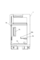
- FIG. 5 is a front schematic view showing a safety cabinet of the culture operation device according to one embodiment of the present invention. Of these, FIG. 5 is a schematic view showing the exterior of the safety cabinet.
- FIG. 6 is a side schematic view showing a safety cabinet of the culture operation device according to one embodiment of the present invention. The schematic side view shown in FIG. 6 shows the interior portion of the safety cabinet.
- the "vertical direction” refers to the direction of gravity of the earth (vertical direction in FIG. 1)
- the "first horizontal direction” and the “second horizontal direction” are planes orthogonal to the vertical direction. Refers to two directions orthogonal to each other within (the first horizontal direction is the left-right direction in FIG. 1 and the up-down direction in FIG. 2, and the second horizontal direction is the left-right direction in FIG. 2).
- the culture operation device is provided inside the safety cabinet 7, the control unit 1 provided outside the safety cabinet 7, and the inside of the safety cabinet 7. It includes a plurality of containers C, a plurality of pipette tips T, a stage 2, a mounting member 3, a capper 4, a pipette member 5, and a moving member 6.
- the container C is a container for storing a medium for cell culture, a cell solution, and the like.
- each of the containers C has a container body CB forming a storage space and a cap CL for closing the opening of the container body CB (FIG. 1). 4).
- the container C is divided into a first bottle C1, a second bottle C2, and a third bottle C3.
- the first bottle C1 is a bottle having a circular cross section of the container body CB (in this embodiment, there are five). All the first bottles C1 are housed in the fixed storage part 311.
- the second bottle C2 is a bottle having a rectangular cross section of the container body CB (in the present embodiment, there is one).
- the second bottle C2 is housed in the movable storage unit 312 and may be a multi-layer cell culture bottle.
- the interior of the second bottle C2 may have a funnel structure or other structure that favors the concentration, flow and distribution of the medium and cell solutions.
- the third bottle C3 is a bottle having a regular octagonal cross section of the container body CB (in the present embodiment, there are two).
- One third bottle C3 is housed in the fixed storage section 311 and the other third bottle C3 is housed in the movable storage section 312.
- the plurality of pipette tips T cooperate with the pipette member 5 to quantitatively collect the medium and the cell solution from different containers C, and inject the collected medium and the cell solution into the other container C. Achieves quantitative pipette work.
- Each pipette tip T has an opening that matches the insertion portion 51 of the pipette member 5, and the lower end portion of each pipette tip T has a tapered shape toward the lower end.
- the stage 2 is installed on the work table 72 in the safety cabinet 7 (see FIGS. 1, 2 and 6).
- the stage 2 has a work surface 2a extending along the horizontal direction.
- a mounting member 3, a capper 4, a pipette member 5, and a moving member 6 are installed on the work surface 2a.
- the mounting member 3 is provided for mounting the container body CB, the cap CL, and the plurality of pipette tips T of the container C, respectively.
- the mounting member 3 includes the container body accommodating portion 31, the cap embedding portion 32, the pipette tip accommodating portion 33, and the pipette. It has a chip collecting unit 34.
- the container body accommodating portion 31 accommodates the container body CB of the corresponding container C and has an accommodating space that matches the cross-sectional shape of the container body CB.
- the container body accommodating portion 31 has a fixed accommodating portion 311 that cannot rotate with respect to the work surface 2a and a movable accommodating portion 312 that is rotatable with respect to the work surface 2a.
- the fixed storage unit 311 holds the corresponding container body CB at a predetermined angle with respect to the work surface 2a.
- the fixed storage unit 311 holds the corresponding container body CB so that its central axis is orthogonal to the work surface 2a. That is, the central axis of the container body CB is along the vertical direction V. This orthogonality is an example of a "predetermined angle".
- the pipette member 5 uses the pipette tip T to use the pipette tip T to view the container body CB from above the container body CB. It is possible to enter inside and perform sampling work and injection work.
- each fixed storage unit 311 is provided with a holding module for holding the container body CB of the container C. Since the sandwiching module has two sandwiching portions 313 that approach or separate from each other in the first horizontal direction H1, the container body CB of the container C is fixedly held by the two sandwiching portions 313, and the container body CB is accommodated in the container body CB. It can be fixed to the portion 31. In this way, in the process of operating the cap CL of the container C by the capper 4 to engage or separate the cap CL from the container body CB, the container body CB does not become rotatable with the operation of the capper 4.
- the movable storage unit 312 rotatably holds the corresponding container body CB with respect to the work surface 2a.
- the central axis of the second bottle C2 is the first horizontal direction H1. It is possible to have a predetermined angle around the work surface 2a. Since the movable accommodating portion 312 for accommodating the one third bottle C3 is rotatable around the first horizontal direction H1 and the second horizontal direction H2, the central axis of the third bottle C3 is the third. It is possible to have a predetermined angle with respect to the work surface 2a around the horizontal direction H1 of 1 and the second horizontal direction H2.
- the central axes of the second bottle C2 and the third bottle C3 may be arranged parallel to the horizontal plane, and the second bottle C2 and the third bottle C3 can rotate around their respective axes. It may be arranged. As described above, it is advantageous to inject the medium and the cell solution into the second bottle C2 and the third bottle C3, and it is also advantageous to uniformly mix and distribute the medium and the cell solution.
- the cap mounting portion 32 is provided for mounting the cap CL removed from the container C.
- the cap mounting portion 32 is formed with a recess 321 (storage portion) that matches the shape of each cap CL, so that the recess 321 can accommodate the corresponding cap CL.
- the distribution of the recesses 321 formed in the cap mounting portion 32 matches the distribution of the container body accommodating portion 31 so that the system can easily identify the removed cap CL and its corresponding recesses 321. That is, in the present embodiment, the positions of the recess 321 of the cap mounting portion 32 and the cap CL of the container C accommodating portion correspond to each other, and in the second horizontal direction H2 of each recess 321 and the corresponding cap CL.
- the corresponding cap CL is placed in the corresponding recess 321 by being equal to the distance of.
- a positioning convex portion protruding outward in the radial direction is formed on the outer peripheral wall of at least a part of the cap CLs of the plurality of containers C, and positioning is performed on the inner peripheral wall of the concave portion 321 that matches the cap CL.
- a positioning recess (not shown) that matches the protrusion is formed.
- the pipette tip accommodating portion 33 is provided to accommodate the pipette tip T before use.
- the pipette tip T before use has one region because there are eight pipette tip accommodating portions 33 and they are arranged in an array in the first horizontal direction H1 and the second horizontal direction H2. It is compactly located inside and easy to manage.
- the pipette tip collecting unit 34 is provided to collect the used pipette tip T.
- similarly to the pipette tip accommodating portion 33 there are eight pipette tip collecting portions 34, and the pipette tip collecting portions 34 are arranged in an array in the first horizontal direction H1 and the second horizontal direction H2.
- the used pipette tip T is compactly located in one area and is easy to manage.
- the capper 4 is provided to realize the engaging work and the separating work of the cap CL and the corresponding container body CB by operating the cap CLs of different containers C.
- the capper 4 has an engaging claw 41 that can be engaged with the cap CL of the container C and can rotate in two directions around the vertical direction V.
- the engaging claw 41 has three claw portions 411 that are uniformly distributed in the circumferential direction of the cap CL, so that the cap CL of the container C can be tightened or loosened.
- the engaging claw 41 engages with the cap CL attached to the container body CB of the container C from the outside, and then rotates in one direction to remove the cap CL from the container body CB, and the cap CL and the container body CB Can be separated.
- the engaging claw 41 can close the opening of the container body CB by engaging the cap CL and the container body CB.
- the capper 4 further includes a rotation module 42 that rotates the engaging claw 41 in two directions.
- the rotary module 42 can determine whether or not the cap CL is securely engaged with the container body CB according to the magnitude of the torque.
- the capper 4 further includes a torque detecting member capable of detecting the torque (resistance) received when the engaging claw 41 rotates around the vertical direction V.
- the control unit 1 controls the engaging claw 41 so as to be separated from the cap CL. That is, the control unit 1 controls the cap CL 4 to stop the work on the cap CL.
- the cap CL with the positioning protrusion is placed in the recess 321 by the engaging claw 41, when it is first placed in the recess 321, it is always placed in the phase in which the cap CL and the recess 321 are perfectly engaged. Not exclusively. In this case, the engaging claw 41 rotates while applying a constant downward pressure to the cap CL.
- the cap CL and the recess 321 rotate in a phase in which they are perfectly engaged, the cap CL is pushed into the recess 321 by the downward pressure of the engaging claw 41.
- the control unit 1 controls the engaging claw 41 so as to move away from the cap CL and return.
- the engaging claw 41 screwes the cap CL into the container body CB
- the engaging claw 41 is first rotated at a constant angle in the direction of loosening the cap CL (the size of the angle is large according to each parameter of the screw). ), Engage the screw of the cap CL with the screw of the container body CB, and then rotate the cap CL in the tightening direction to tighten it.
- the predetermined value is larger than the torque of the frictional force to be overcome when the engaging claw 41 presses the cap CL against the surface of the cap mounting portion 32 to rotate, and when the capper 4 is blocked and does not continue to rotate. It is less than the torque when the load of the drive motor is too high and damage occurs.
- the pipette member 5 selectively attaches / detaches different pipette tips T, and pipettes the container body CB are performed by the attached pipette tips T.
- the pipette member 5 includes an assembled insertion section 51 and a unloading section 52.
- the insertion portion 51 has a cylindrical shape and extends along the vertical direction V. Since the insertion portion 51 has an outer diameter that matches the inner diameter of the pipette tip T, the insertion portion 51 can be inserted into the pipette tip T and securely joined to the pipette tip T by tight fitting. Further, the insertion portion 51 is further provided with a pipette hole that enables pipette work of the pipette tip T joined to the insertion portion 51 by generating suction input and discharge force.
- the unloading portion 52 fits outside the insertion portion 51 and is movable with respect to the inserting portion 51 along the vertical direction V.
- the pipette tip T can be removed from the insertion portion 51 by the relative movement of the unloading portion 52 and the insertion portion 51. That is, the unloading unit 52 that moves with respect to the insertion unit 51 can support the pipette tip T to separate (disconnect) the pipette tip T and the insertion unit 51.
- the pipette member 5 further has a minute amount measuring pipette unit 53 that is not joined to the pipette tip T and collects a quantitative solution from the inside of the container C.
- the micro-quantity metering pipette unit 53 has a liquid sampling head that performs a micro-quantity liquid sampling operation on a medium and a cell solution. The liquid sampling head can also be applied to other applications.
- the moving member 6 arranges the capper 4 and the pipette member 5 in three directions, a vertical direction V, a first horizontal direction H1 and a second horizontal direction H2, which are orthogonal to each other with respect to the mounting member 3. Displace relatively.
- the moving member 6 has a frame and three moving rails Rv, Rh1 and Rh2 provided on the frame.
- the three rails Rv, Rh1 and Rh2 extend along the three directions of the vertical direction V, the first horizontal direction H1 and the second horizontal direction H2, respectively.
- the moving member 6 has a mechanism for displacing the mounting member 3 within a predetermined range along the rail Rh1 extending along the first horizontal direction H1, and the capper 4 and the pipette member 5 for the second horizontal direction.
- the control unit 1 includes a CPU, a memory, and the like, and is connected to the moving member 6, the capper 4, and the pipette member 5 so as to be able to transmit and receive control signals by wire or wirelessly.
- the control unit 1 realizes the relative displacement of the moving member 6, engages and separates the capper 4, and selectively attaches / detaches different pipette tips T of the pipette member 5 according to a predetermined program stored in the memory. And pipette work can be controlled.
- the control unit 1 includes an overall control unit 11, a pipette control unit 12, a rotation control unit 13, a cap rotation control unit 14, and a cylinder control unit 15. By controlling the operation of each member, these control units perform each of the above operations according to a predetermined program.
- the safety cabinet 7 is provided to provide a sterile working environment.
- the stage 2 is installed on a removable work table 72 in the safety cabinet 7.
- the safety cabinet 7 includes a housing 71, an exhaust module 73, a measurement module 74, a sterilization module 75, a lighting module 76, and a movement adjustment module 77.
- the housing 71 has a cubic shape and forms a sterile working environment inside.
- the workbench 72 is mounted inside the housing 71 and is arranged horizontally.
- the exhaust module 73 is provided to communicate the inside and the outside of the housing 71.
- the exhaust module 73 includes an air supply port 731 and an exhaust port 735 provided in the housing 71, an air supply filter 732 provided in the housing 71 and located at the air supply port 731 (in the present embodiment, there are two).
- an exhaust filter 734 (in this embodiment, there is one) provided in the housing 71 and located at the exhaust port 735, dust, particles, and the like are filtered when gas is exchanged inside and outside the housing 71.
- the exhaust module 73 further includes a blower 733 provided inside the exhaust port 735. The blower 733 is provided to promote air exchange inside and outside the housing 71.
- the exhaust module 73 further includes an exhaust filter differential pressure gauge 736 that monitors the pressure difference of the exhaust filter 734.
- the measurement module 74 is provided to measure a predetermined parameter in the housing 71.
- the measurement module 74 has a particle counter 741 for measuring the concentration of dust and particles in the housing 71, and a PAO inlet side measurement valve 742 for measuring the input of PAO (polyalphaolefin). It is possible to provide the user with desired parameter information.
- the sterilization module 75 is provided in the housing 71 and is provided for sterilizing the inside of the housing 71. Specifically, the sterilization module 75 can effectively sterilize the internal space of the housing 71 by having two germicidal lamps (15W) provided on the side wall of the housing 71.
- the lighting module 76 is provided to illuminate the inside of the housing 71.
- the lighting module 76 includes three LEDs provided at the top of the interior space of the housing 71.
- the movement adjustment module 77 is arranged in the lower part of the housing 71, and is provided to move the housing 71 and adjust the angle between the housing 71 and the ground.
- the movement adjustment module 77 has a plurality of rollers 771, a plurality of adjusters 772, and a plurality of support legs 773.
- the roller 771 is advantageous for the housing 71 to move to the ground when moving.
- the adjuster 772 is provided to support the housing 71 while adjusting the angle between the housing 71 and the ground. After the support leg 773 is placed underneath, it acts as a support for the housing 71.
- the operation display unit 78 is arranged on the outer wall of the housing 71, and is provided to display the parameters in the housing 71 and to input the operation command for controlling the operation of each member of the safety cabinet 7. Has been done.
- the octagonal bottle is the third bottle C3, and the culture bottle, the medium recovery bottle, the PBS bottle, the trypsin bottle, and the waste liquid bottle are the first bottle C1 or the second bottle C2. It is possible to select.
- the operation process of medium exchange can be automatically realized (see Table 1).
- the cell recovery process can be automatically realized (see Table 2).
- the present invention provides a new culture manipulation device. It is not necessarily the example described in the specific embodiment described above. In addition, a supplementary explanation will be given as follows.
- the working surface 2a of the stage 2 is horizontal, but the present invention is not limited to this. If necessary, the work surface 2a may be set to form a predetermined angle with respect to the horizontal plane.
- all the first bottle C1 can be replaced with the third bottle C3. Specifically, it can be selected as needed.
- the safety cabinet 7 may have a desired power socket and power cord. Further, the housing 71 may have a removable structure for maintenance and a transparent structure for easily observing the internal space.
Landscapes
- Engineering & Computer Science (AREA)
- Health & Medical Sciences (AREA)
- Chemical & Material Sciences (AREA)
- Life Sciences & Earth Sciences (AREA)
- Bioinformatics & Cheminformatics (AREA)
- Wood Science & Technology (AREA)
- Organic Chemistry (AREA)
- Zoology (AREA)
- Biotechnology (AREA)
- Biomedical Technology (AREA)
- Sustainable Development (AREA)
- Microbiology (AREA)
- Biochemistry (AREA)
- General Engineering & Computer Science (AREA)
- General Health & Medical Sciences (AREA)
- Genetics & Genomics (AREA)
- Medicinal Chemistry (AREA)
- Analytical Chemistry (AREA)
- Computer Hardware Design (AREA)
- Clinical Laboratory Science (AREA)
- Cell Biology (AREA)
- Virology (AREA)
- Apparatus Associated With Microorganisms And Enzymes (AREA)
Priority Applications (1)
| Application Number | Priority Date | Filing Date | Title |
|---|---|---|---|
| JP2022508727A JPWO2021187610A1 (https=) | 2020-03-18 | 2021-03-18 |
Applications Claiming Priority (2)
| Application Number | Priority Date | Filing Date | Title |
|---|---|---|---|
| CN202010192454.9 | 2020-03-18 | ||
| CN202010192454.9A CN113493734A (zh) | 2020-03-18 | 2020-03-18 | 培养操作装置 |
Publications (1)
| Publication Number | Publication Date |
|---|---|
| WO2021187610A1 true WO2021187610A1 (ja) | 2021-09-23 |
Family
ID=77768164
Family Applications (1)
| Application Number | Title | Priority Date | Filing Date |
|---|---|---|---|
| PCT/JP2021/011263 Ceased WO2021187610A1 (ja) | 2020-03-18 | 2021-03-18 | 培養操作装置 |
Country Status (3)
| Country | Link |
|---|---|
| JP (1) | JPWO2021187610A1 (https=) |
| CN (1) | CN113493734A (https=) |
| WO (1) | WO2021187610A1 (https=) |
Cited By (1)
| Publication number | Priority date | Publication date | Assignee | Title |
|---|---|---|---|---|
| WO2025142790A1 (ja) * | 2023-12-26 | 2025-07-03 | 三菱重工業株式会社 | フラスコトレイ、フラスコユニット及び細胞培養システム |
Family Cites Families (3)
| Publication number | Priority date | Publication date | Assignee | Title |
|---|---|---|---|---|
| JP2004305148A (ja) * | 2003-04-09 | 2004-11-04 | Olympus Corp | 自動培養装置 |
| WO2016170623A1 (ja) * | 2015-04-22 | 2016-10-27 | 株式会社安川電機 | 細胞培養システム及び細胞培養方法 |
| CN209890608U (zh) * | 2019-03-14 | 2020-01-03 | 广州蓝勃生物科技有限公司 | 一种培养皿开合盖装置 |
-
2020
- 2020-03-18 CN CN202010192454.9A patent/CN113493734A/zh active Pending
-
2021
- 2021-03-18 JP JP2022508727A patent/JPWO2021187610A1/ja active Pending
- 2021-03-18 WO PCT/JP2021/011263 patent/WO2021187610A1/ja not_active Ceased
Non-Patent Citations (4)
| Title |
|---|
| ANONYMOUS: "iPS cell automatic culture device-faithfully reproduces the culture technology of experts Accelerate research in the fields of regenerative medicine and drug discovery", PANASONIC - NEWS, 28 February 2018 (2018-02-28), XP055859351, Retrieved from the Internet <URL:https://news.panasonic.com/jp/stories/2018/55493.html> [retrieved on 20210422] * |
| ANONYMOUS: "Technology that support Decode: fully-automated cell culture device", RIKEN, 19 February 2020 (2020-02-19), Retrieved from the Internet <URL:https://webarchive.org/web/20200219084735/https://decode.riken.jp:80/jp/technology/tech_culture.html> [retrieved on 20210422] * |
| CHANNEL PANASONIC - OFFICIAL: "IPS", YOUTUBE, 28 February 2018 (2018-02-28), XP055859503, Retrieved from the Internet <URL:https://www.youtube.com/watch?v=RtxGCWC7N54> [retrieved on 20210422] * |
| LAB FRUSAWA: "Fully-automated culture system in Furusawa Lab", YOUTUBE, 19 May 2016 (2016-05-19), XP055859518, Retrieved from the Internet <URL:https://www.youtube.com/watch?v=4k6qCN7ppsk> [retrieved on 20210422] * |
Cited By (1)
| Publication number | Priority date | Publication date | Assignee | Title |
|---|---|---|---|---|
| WO2025142790A1 (ja) * | 2023-12-26 | 2025-07-03 | 三菱重工業株式会社 | フラスコトレイ、フラスコユニット及び細胞培養システム |
Also Published As
| Publication number | Publication date |
|---|---|
| CN113493734A (zh) | 2021-10-12 |
| JPWO2021187610A1 (https=) | 2021-09-23 |
Similar Documents
| Publication | Publication Date | Title |
|---|---|---|
| KR102489816B1 (ko) | 살균 용액 제품 백들을 생산하는 방법 및 기계 | |
| EP2285337B1 (en) | Automated workstation for the secure preparation of a final product for medical or pharmaceutical use | |
| CN112940917A (zh) | 自动化细胞培养设备 | |
| WO2012141055A1 (ja) | 細胞培養装置、及び搬送装置 | |
| JP2009544391A (ja) | 医薬品の調製装置 | |
| CN110480391A (zh) | 一种适用于大型复杂工件加工和装配的自动换刀系统 | |
| WO2021187610A1 (ja) | 培養操作装置 | |
| JP2012504427A (ja) | 細胞及び/又はバクテリア培養用の培養/暴露装置 | |
| JP2017503147A (ja) | 車両用キャニスター検査装置 | |
| CN115494803A (zh) | 一种全流程集成化药品研发工作站 | |
| US20050145295A1 (en) | Adjustable needle filling and laser sealing apparatus and method | |
| CN100590433C (zh) | 试样分析仪的试样传送方法和试样瓶操作系统 | |
| JP5337387B2 (ja) | 全自動細穴加工システム | |
| CN118992167A (zh) | 透析干粉桶自动灌装机 | |
| CN116021274B (zh) | 安全阀装配机 | |
| JP7813699B2 (ja) | 細胞回収装置用ロボット及び細胞回収方法 | |
| CN116445272A (zh) | 一种自动化集菌系统 | |
| JP7756074B2 (ja) | 細胞回収装置及び細胞回収方法 | |
| CN112894358B (zh) | 一种玻璃移液管全自动组装设备 | |
| CN220542858U (zh) | 药品检测滴定装置 | |
| CN222717993U (zh) | 一种具有气体泄漏检测功能的特气柜 | |
| US20260056092A1 (en) | Sampling system and sampling method | |
| CN223289320U (zh) | 一种阀底杯组件组装设备以及组阀生产线 | |
| CN209237903U (zh) | 一种化学实验用液体供料装置 | |
| CN117124010B (zh) | 一种高度集成的航空液压柱塞泵修理线及其使用方法 |
Legal Events
| Date | Code | Title | Description |
|---|---|---|---|
| 121 | Ep: the epo has been informed by wipo that ep was designated in this application |
Ref document number: 21772256 Country of ref document: EP Kind code of ref document: A1 |
|
| ENP | Entry into the national phase |
Ref document number: 2022508727 Country of ref document: JP Kind code of ref document: A |
|
| NENP | Non-entry into the national phase |
Ref country code: DE |
|
| 122 | Ep: pct application non-entry in european phase |
Ref document number: 21772256 Country of ref document: EP Kind code of ref document: A1 |