WO2021187555A1 - 異方性光学フィルム用組成物及び異方性光学フィルム - Google Patents
異方性光学フィルム用組成物及び異方性光学フィルム Download PDFInfo
- Publication number
- WO2021187555A1 WO2021187555A1 PCT/JP2021/011056 JP2021011056W WO2021187555A1 WO 2021187555 A1 WO2021187555 A1 WO 2021187555A1 JP 2021011056 W JP2021011056 W JP 2021011056W WO 2021187555 A1 WO2021187555 A1 WO 2021187555A1
- Authority
- WO
- WIPO (PCT)
- Prior art keywords
- optical film
- component
- anisotropic optical
- light
- composition
- Prior art date
- Legal status (The legal status is an assumption and is not a legal conclusion. Google has not performed a legal analysis and makes no representation as to the accuracy of the status listed.)
- Ceased
Links
- 0 C*=CCc(c(*)c(*)c(Oc1c(C)c(*)c(*)c(*)c1*)c1*)c1O Chemical compound C*=CCc(c(*)c(*)c(Oc1c(C)c(*)c(*)c(*)c1*)c1*)c1O 0.000 description 1
- HHQAGBQXOWLTLL-UHFFFAOYSA-N C=CC(OCC(COc1ccccc1)O)=O Chemical compound C=CC(OCC(COc1ccccc1)O)=O HHQAGBQXOWLTLL-UHFFFAOYSA-N 0.000 description 1
- VAZQKPWSBFZARZ-UHFFFAOYSA-N C=CC(OCCOc(cccc1)c1-c1ccccc1)=O Chemical compound C=CC(OCCOc(cccc1)c1-c1ccccc1)=O VAZQKPWSBFZARZ-UHFFFAOYSA-N 0.000 description 1
- BXSPZNVFEYWSLZ-UHFFFAOYSA-N C=CC(OCc1cc(Oc2ccccc2)ccc1)=O Chemical compound C=CC(OCc1cc(Oc2ccccc2)ccc1)=O BXSPZNVFEYWSLZ-UHFFFAOYSA-N 0.000 description 1
Images




Classifications
-
- C—CHEMISTRY; METALLURGY
- C08—ORGANIC MACROMOLECULAR COMPOUNDS; THEIR PREPARATION OR CHEMICAL WORKING-UP; COMPOSITIONS BASED THEREON
- C08F—MACROMOLECULAR COMPOUNDS OBTAINED BY REACTIONS ONLY INVOLVING CARBON-TO-CARBON UNSATURATED BONDS
- C08F2/00—Processes of polymerisation
- C08F2/44—Polymerisation in the presence of compounding ingredients, e.g. plasticisers, dyestuffs, fillers
-
- C—CHEMISTRY; METALLURGY
- C08—ORGANIC MACROMOLECULAR COMPOUNDS; THEIR PREPARATION OR CHEMICAL WORKING-UP; COMPOSITIONS BASED THEREON
- C08F—MACROMOLECULAR COMPOUNDS OBTAINED BY REACTIONS ONLY INVOLVING CARBON-TO-CARBON UNSATURATED BONDS
- C08F263/00—Macromolecular compounds obtained by polymerising monomers on to polymers of esters of unsaturated alcohols with saturated acids as defined in group C08F18/00
- C08F263/02—Macromolecular compounds obtained by polymerising monomers on to polymers of esters of unsaturated alcohols with saturated acids as defined in group C08F18/00 on to polymers of vinyl esters with monocarboxylic acids
- C08F263/04—Macromolecular compounds obtained by polymerising monomers on to polymers of esters of unsaturated alcohols with saturated acids as defined in group C08F18/00 on to polymers of vinyl esters with monocarboxylic acids on to polymers of vinyl acetate
-
- G—PHYSICS
- G02—OPTICS
- G02B—OPTICAL ELEMENTS, SYSTEMS OR APPARATUS
- G02B5/00—Optical elements other than lenses
- G02B5/02—Diffusing elements; Afocal elements
-
- G—PHYSICS
- G02—OPTICS
- G02B—OPTICAL ELEMENTS, SYSTEMS OR APPARATUS
- G02B5/00—Optical elements other than lenses
- G02B5/30—Polarising elements
-
- C—CHEMISTRY; METALLURGY
- C08—ORGANIC MACROMOLECULAR COMPOUNDS; THEIR PREPARATION OR CHEMICAL WORKING-UP; COMPOSITIONS BASED THEREON
- C08J—WORKING-UP; GENERAL PROCESSES OF COMPOUNDING; AFTER-TREATMENT NOT COVERED BY SUBCLASSES C08B, C08C, C08F, C08G or C08H
- C08J5/00—Manufacture of articles or shaped materials containing macromolecular substances
- C08J5/18—Manufacture of films or sheets
Definitions
- the present invention relates to a composition for an anisotropic optical film and an anisotropic optical film produced by using a composition for an anisotropic optical film.
- Various display devices such as a liquid crystal display device (LCD) and an organic electroluminescence element (organic EL) may be provided with an anisotropic light diffusing film for the purpose of expanding the viewing angle and the like.
- LCD liquid crystal display device
- organic EL organic electroluminescence element
- Patent Document 1 describes a (meth) acrylic acid ester containing a plurality of aromatic rings as a component (A). , A urethane (meth) acrylate as a component (B), a photopolymerization initiator as a component (C), and a specific hindered amine-based light stabilizer as a component (D), and a component (A).
- the content of the component (B) is set to a value within the range of 25 to 400 parts by weight with respect to 100 parts by weight of the component (B), and the content of the component (C) is the total of the components (A) and (B).
- the value is set in the range of 0.2 to 20 parts by weight with respect to the amount (100 parts by weight), and the content of the component (D) is the total amount of the components (A) and (B) (100 parts by weight).
- a value in the range of 0.1 to 10 parts by weight is disclosed.
- the light diffusing film disclosed in Patent Document 1 has a good incident angle dependence in light diffusion and transmission, it has insufficient transparency and exhibits a tint (hue b *). The value is 0.56 or more and it is yellowish). In addition, this light diffusing film may reduce the optical performance of the display device, particularly the contrast.
- the present invention provides anisotropic optics for producing a light diffusing film capable of achieving both good diffusivity and good hue, and further suppressing a decrease in contrast when incorporated into a display device.
- An object is to provide a composition for a film.
- the light diffusing film according to Patent Document 1 uses a (meth) acrylic acid ester containing a plurality of aromatic rings. Therefore, in the molecular structure after photocuring, ⁇ - ⁇ stacking interaction between aromatic rings is likely to occur, and this interaction allows ⁇ electrons to be conjugated to a wide range in the molecular structure. As a result, it is considered that the light absorption wavelength of the light diffusion film is shifted to the visible light region on the long wavelength side, and the light is exhibited in color.
- Patent Document 1 states that "yellowing is unlikely to occur even when exposed to ultraviolet rays for a long time", in Table 1 of Examples, the initial stage of b * The value is "0.56 or more", and at the stage of the initial value, it has already been yellowish.
- the molecular structure after photocuring tends to be oriented in a specific direction, and as a result, birefringence occurs. It was considered that the light diffusing film had a phase difference. Further, when such a light diffusing film is arranged between the liquid crystal cell and the polarizing plate for the purpose of expanding the viewing angle or improving the brightness, for example, the polarization is disturbed, so that light leakage occurs in the cross Nicol arrangement. It was considered that the parallel Nicol arrangement would cause light loss and reduce the optical performance of the display device, especially the contrast.
- the present invention is as follows.
- the present invention (A) As a component, a (meth) acrylic acid ester having a plurality of aromatic rings and one (meth) acryloyl group, and The following (b1) component and / or (b2) component as the component (B), and a (meth) acrylic acid ester different from the component (A), (C) A composition containing a thermoplastic polymer having a weight average molecular weight of 1,000 to 500,000 and a glass transition temperature of ⁇ 40 ° C. or higher as a component.
- the content of the component (B) in the composition is 50 parts by weight to 1000 parts by weight when the content of the component (A) is 100 parts by weight.
- the content of the component (C) in the composition is 10 parts by weight to 400 parts by weight when the contents of the component (A) and the component (B) are 100 parts by weight.
- This is a composition for an anisotropic optical film.
- [(B1) component] A (meth) acrylic acid ester having a plurality of (meth) acryloyl groups
- [(b2) component] A (meth) acrylic acid ester having any one or more of hydroxyl groups, carboxyl groups or amino groups, and one (meth) acryloyl group.
- the refractive index of the component (A) may be 1.5 or more and less than 1.65.
- the component (A) may have a biphenyl ring structure.
- the component (A) may have a diphenyl ether structure.
- the component (B) may have at least one aromatic ring structure.
- the refractive index of the component (C) may be 1.35 or more and less than 1.5.
- the composition for an anisotropic optical film may contain a photopolymerization initiator as the component (D).
- the present invention An anisotropic optical film that is a cured product of the composition for an anisotropic optical film.
- the anisotropic optical film is a film in which the linear transmittance changes (the amount of incident light transmitted in the linear direction) / (the amount of incident light transmitted) depending on the incident angle of light.
- the anisotropic optical film may be an anisotropic optical film characterized by having a matrix region and a plurality of columnar regions having different refractive indexes from the matrix region.
- the plurality of columnar regions of the anisotropic optical film are oriented and extended from one surface of the anisotropic optical film to the other surface.
- the aspect ratio of the columnar region which is the average major axis / average minor axis of the columnar region in the cross section perpendicular to the column axis of the anisotropic optical film, may be 1 or more and 50 or less.
- the thickness of the anisotropic optical film may be 20 ⁇ m to 500 ⁇ m.
- the hue b * of the anisotropic optical film may be ⁇ 2.00 or more and less than 0.55.
- 5% is added to the value of the minimum linear transmittance, which is the linear transmittance of the light incident on the anisotropic optical film at the incident light angle at which the linear transmittance of the incident light is minimized.
- the angular range of the two incident light angles with respect to the value of the linear transmittance may be 20 ° or more.
- the change in leakage transmittance may be less than 0.8%.
- Compositions for optical films can be provided.
- the composition for an anisotropic optical film according to the present invention the anisotropic optical film obtained by curing the composition for an anisotropic optical film, and the like will be described.
- the composition for an anisotropic optical film is a composition used for producing an anisotropic optical film.
- the refractive index of each component is measured by a method based on JIS K0062.
- composition for an anisotropic optical film comprises a first (meth) acrylic acid ester (A) component, a second (meth) acrylic acid ester (B) component, and a thermoplastic polymer. Contains certain (C) components.
- composition for an anisotropic optical film preferably contains the component (D) which is a photopolymerization initiator. Further, the composition for an anisotropic optical film may contain the component (E) which is another component.
- the component (A) is a (meth) acrylic acid ester having a plurality of aromatic rings and one (only one) (meth) acryloyl group.
- the component (A) preferably has a biphenyl ring structure or a diphenyl ether structure as a structure containing a plurality of aromatic rings.
- a biphenyl structure or a diphenyl ether structure may have only one or two or more in the skeleton. By having such a structure, it becomes a (meth) acrylic acid ester having a very high refractive index.
- the component (A) is usually a high refractive index material.
- the refractive index of the component (A) is preferably 1.50 or more, more preferably 1.53 or more, and even more preferably 1.56 or more.
- the upper limit of the refractive index is not particularly limited, but is preferably 1.65 or less, for example.
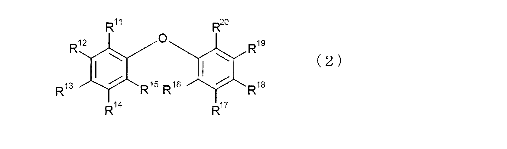
- the component (A) is not particularly limited, and examples thereof include a biphenyl compound represented by the following general formula (1), a diphenyl ether compound represented by the following general formula (2), and the like.
- R 1 to R 10 are independent of each other, and any one of R 1 to R 10 is a substituent represented by the following general formula (3) or (4).
- the rest need not contain (meth) acryloyl groups, specifically hydrogen atoms, hydroxyl groups, carboxyl groups, alkyl groups, alkoxy groups, alkyl halide groups, hydroxyalkyl groups, carboxyalkyl groups and halogens. Substituents such as atoms can be mentioned.
- R 11 to R 20 are independent of each other, and any one of R 11 to R 20 is a substituent represented by the following general formula (3) or (4). ..
- the rest need not contain (meth) acryloyl groups, specifically hydrogen atoms, hydroxyl groups, carboxyl groups, alkyl groups, alkoxy groups, alkyl halide groups, hydroxyalkyl groups, carboxyalkyl groups and halogens. Substituents such as atoms can be mentioned.
- R 21 is a hydrogen atom or a methyl group, the number of carbon n is an integer of 1 to 4, and the number of repetitions m is an integer of 1 to 10.
- R 22 is a hydrogen atom or a methyl group, the number of carbon n is an integer of 1 to 4, and the number of repetitions m is an integer of 1 to 10.
- the number of repetitions m in the substituents represented by the general formulas (3) and (4) is usually preferably an integer of 1 to 10.
- the reason for this is that when the number of repetitions m exceeds 10, the effect of improving the refractive index derived from the aromatic ring peculiar to the component (A) is suppressed, and the diffusivity of the anisotropic optical film may decrease. Because. Therefore, the number of repetitions m in the substituents represented by the general formulas (3) and (4) is more preferably an integer of 1 to 4, and further preferably an integer of 1 to 2.
- the number of carbon atoms n in the substituents represented by the general formulas (3) and (4) is usually preferably an integer of 1 to 4, and more preferably an integer of 1 to 2.
- biphenyl compound represented by the general formula (1) As a specific example of the biphenyl compound represented by the general formula (1), a compound represented by the following formula (5) can be preferably mentioned.
- the component (A) may contain only one kind of the above-mentioned component, or may contain a plurality of kinds.
- the component (B) is a component different from the component (A), and is a component (b1) and / or a component (b2).
- the component (B) may be either the component (b1) or the component (b2), or may include both the component (b1) and the component (b2).
- the component (b1) is a (meth) acrylic acid ester having a plurality of (meth) acryloyl groups.
- the number of (meth) acryloyl groups contained in the component (b1) is not particularly limited, but may be 2 to 3 in order to improve the flexibility of the anisotropic optical film after photocuring, or after photocuring. It may be 4 to 6 in order to improve the rigidity and heat resistance of the film.
- the component (b1) is not particularly limited, and examples thereof include pentaerythritol tetraacrylate represented by the following general formula (7).
- the component (B) contains the component (b1)
- the component (A) may not contain a hydroxyl group, a carboxyl group and an amino group.
- the component (b2) is a (meth) acrylic acid ester having at least one of a hydroxyl group, a carboxyl group, or an amino group, and one (only one) (meth) acryloyl group.
- the component (b2) may have two or more hydroxyl groups, carboxyl groups or amino groups. In that case, it may have two or more functional groups of the same type (for example, two or more hydroxyl groups), or a total of two or more different functional groups (for example, one or more hydroxyl groups and a carboxyl group). (1 or more) may be possessed.
- the component (b2) is not particularly limited, and examples thereof include a (meth) acrylic acid ester represented by the following general formula (8).
- R 25 is a hydrogen atom or a methyl group
- R 26 is either a hydroxyl group, a carboxyl group or an amino group
- R 27 is a hydrogen atom, a hydroxyl group, a carboxyl group or an alkyl.
- Substituents R 26 represented by the above general formula (8) is usually a hydroxyl group, or carboxyl group or amino group.
- the functional groups act as "hydrogen bond donors” and “hydrogen bond acceptors” to generate hydrogen bonds in the molecular structure of the photocurable anisotropic optical film, resulting in a complex three-dimensional structure. This is to make the structure and weaken the ⁇ - ⁇ stacking interaction between the aromatic rings derived from the component (A). Therefore, in order to strongly effect the hydrogen bonds, it is more preferable that the functional group R 26 with hydroxyl groups.
- the substituent, R 27, is usually any of hydrogen atom, hydroxyl group, carboxyl group, alkyl group, alkoxy group, alkyl halide group, hydroxyalkyl group, carboxyalkyl group and halogen atom, among them.
- An alkoxy group having an aromatic ring is more preferable in order to increase the refractive index.
- the component (B) is preferably a high refractive index material.
- the value of the refractive index is not particularly limited, but specifically, it is preferably 1.44 or more, more preferably 1.48 or more, and further preferably 1.52 or more.
- the upper limit of the refractive index is not particularly limited, but is preferably 1.57 or less, for example.
- the component (B) is a high-refractive-index material as described above, it is preferable that the component (B) has an aromatic ring structure.
- the component (B) may contain only one kind of the above-mentioned component, or may contain a plurality of kinds.
- the component (A) is considered to be useful as a polymerizable compound having a high refractive index, but ⁇ - ⁇ stacking interaction occurs. As described above, it is considered that the ⁇ - ⁇ stacking interaction causes the color to be exhibited.
- the component (b1) as the component (B), the structure of the composition for anisotropic optical film after photocuring is complicated by the plurality of (meth) acryloyl groups contained in the component (b1). It has a three-dimensional structure and makes it difficult for ⁇ - ⁇ stacking interactions between aromatic rings to occur.
- the component (b2) has a functional group for acting as a "hydrogen bond donor” and a "hydrogen bond acceptor”, and is anisotropic.
- a functional group for exerting such an effect a hydroxyl group, a carboxyl group and an amino group are used.
- the glass transition temperature of the component (C) is ⁇ 40 ° C. or higher, preferably 0 ° C. or higher, and more preferably 30 ° C. or higher.
- the upper limit of the glass transition temperature is not particularly limited, but is preferably 150 ° C. or lower, for example.
- the glass transition temperature can be measured by a known measuring method, for example, a method based on JIS K7121-1987 "Plastic transition temperature measuring method".
- the weight average molecular weight of the component (C) is 1,000 to 500,000, preferably 10,000 to 400,000, and even more preferably 50,000 to 300,000.
- the weight average molecular weight can be measured by a known measuring method, for example, a polystyrene-equivalent molecular weight using the GPC method.
- the compatibility with the components (A) and (B) is enhanced to obtain an anisotropic optical film having excellent performance, and heat resistance. It is possible to improve the durability in tests and the like, to give an anisotropic optical film before UV curing an appropriate elastic modulus, and to enable storage in a roll.
- the component (C) is usually a low-refractive material.
- the refractive index of the component (C) is preferably less than 1.50, more preferably less than 1.49, and even more preferably less than 1.48.
- the lower limit of the refractive index is not particularly limited, but is preferably 1.38 or more, for example.
- the component (C) is not particularly limited, but is, for example, an acrylic resin, a styrene resin, a styrene-acrylic copolymer, a polyurethane resin, a polyester resin, an epoxy resin, a cellulose resin, a silicone resin, or a vinyl acetate resin. , Vinyl chloride-vinyl acetate copolymer, polyvinyl butyral resin, polyvinyl alcohol resin, polyvinyl formal resin, polyvinyl acetal resin, polyvinylidene fluoride, PMMA-PBA block copolymer, PVdF-HFP copolymer, and the like.
- the component (C) may contain only one kind of the above-mentioned component, or may contain a plurality of kinds.
- the photopolymerization initiator of the component (D) is a compound that generates radical species by irradiation with active energy rays such as ultraviolet rays, and conventionally known ones can be used.
- photopolymerization initiator examples include benzophenone, benzyl, Michler's ketone, 2-chlorothioxanthone, 2,4-diethylthioxanthone, benzoin ethyl ether, benzoin isopropyl ether, benzoin isobutyl ether, 2,2-diethoxyacetophenone, and benzyl dimethyl ketal.
- 2,2-Dimethoxy-1,2-diphenylethane-1-one 2-hydroxy-2-methyl-1-phenylpropan-1-one, 1-hydroxycyclohexylphenylketone, 2-methyl-1- [4 -(Methylthio) phenyl] -2-morpholinopropanone-1,1- [4- (2-hydroxyethoxy) -phenyl] -2-hydroxy-2-methyl-1-propane-1-one, bis (cyclopenta) Dienyl) -bis [2,6-difluoro-3- (pyr-1-yl) phenyl] titanium, 2-benzyl-2-dimethylamino-1- (4-morpholinophenyl) -butanone-1,2 Examples thereof include 4,6-trimethylbenzoyldiphenylphosphine oxide.
- These compounds may be used individually or in combination of two or more.
- the photopolymerization initiator may usually be used by directly dissolving the powder in the photopolymerizable compound, but if the solubility is poor, the photopolymerization initiator may be dissolved in a solvent in advance. can.
- the component (E) may contain various known dyes and sensitizers, other known additives, and the like in order to improve photopolymerizability.
- thermosetting initiator capable of curing the photopolymerizable compound by heating can be used in combination with the photopolymerization initiator. In this case, it can be expected that the polymerization curing of the photopolymerizable compound is further promoted and completed by heating after the photocuring.
- a solvent for preparing a composition containing a photopolymerizable compound for example, ethyl acetate, butyl acetate, acetone, methyl ethyl ketone, methyl isobutyl ketone, cyclohexanone, toluene, xylene and the like can be used.
- the content of the component (B) is 50 parts by weight to 1000 parts by weight, more preferably 65 parts by weight to 900 parts by weight, and 75 parts by weight to 75 parts by weight, based on 100 parts by weight of the component (A). It is more preferably 200 parts by weight.
- the content of the component (C) is 10 parts by weight to 400 parts by weight, more preferably 25 parts by weight to 150 parts by weight, based on 100 parts by weight of the contents of the component (A) and the component (B). , 40 parts by weight to 100 parts by weight is more preferable.
- the interaction between the components can be made appropriate.
- the total content of the components (A), (B), and (C) with respect to the total solid content of the composition is not particularly limited, but is 50% by weight. As described above, it can be 60% by weight or more, 70% by weight or more, 80% by weight or more, 90% by weight or more, 95% by weight or more, 99% by weight or more, 100% by weight or more.
- the content of the component (D) is preferably 0.1 part by weight to 20 parts by weight, preferably 0.5 parts by weight, based on 100 parts by weight of the contents of the component (A), the component (B) and the component (C). More preferably, it is by weight to 10 parts by weight.
- the composition for an anisotropic optical film according to the present invention is a light diffusing film capable of achieving both good diffusivity and good hue, and further suppressing a decrease in contrast when incorporated into a display device. Can be manufactured.
- a preferable example of the anisotropic optical film obtained by using the composition for the anisotropic optical film will be described.
- the composition for anisotropic optical film it is possible to produce an anisotropic optical film other than the anisotropic optical film shown below.
- the anisotropic optical film is a film having optical anisotropy in which the linear transmittance [(the amount of transmitted light in the linear direction of the incident light) / (the amount of incident light)] changes depending on the incident angle of light. .. That is, with respect to the incident light on the anisotropic optical film, the incident light in a predetermined angle range is transmitted while maintaining linearity, and the incident light in other angle ranges exhibits diffusivity.
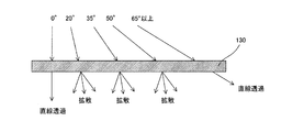
- the anisotropic optical film shown in FIG. 1 exhibits diffusivity when the incident angle is 20 ° to 50 °, does not exhibit diffusivity at other incident angles, and exhibits linear transparency.
- the anisotropic optical film in the present invention has a matrix region and a plurality of columnar regions having a refractive index different from that of the matrix region.
- the plurality of columnar regions included in the anisotropic optical film are usually oriented and extended from one surface of the anisotropic optical film to the other surface (see FIG. 3 and the like).
- the difference in refractive index is not particularly limited as long as there is a difference in the degree to which at least a part of the light incident on the anisotropic optical film is reflected at the interface between the matrix region and the columnar region.
- the difference in refractive index between the matrix region and the columnar region may be 0.001 or more.
- Such a matrix region and a columnar region are formed by phase separation of each component described above.
- the length of the columnar region is not particularly limited, and may be a length that penetrates from one surface of the anisotropic optical film to the other surface, or may be a length that does not reach from one surface to the other surface.
- the surface shape of the plurality of columnar regions included in the anisotropic optical film on the surface of the anisotropic optical film can be a shape having a minor axis and a major axis.
- the surface shape of the columnar region is not particularly limited, and may be, for example, a circle, an ellipse, or a polygon.
- the minor axis and the major axis are equal, in the case of an ellipse, the minor axis is the length of the minor axis, the major axis is the length of the major axis, and in the case of a polygon, it is a polygon.
- the shortest length can be the minor axis and the longest length can be the major axis.
- FIG. 2 shows a columnar region seen from the surface direction of the anisotropic optical film.
- LA represents a major axis
- SA represents a minor axis.
- minor axis and major axis of the columnar region For the minor axis and major axis of the columnar region, observe the surface of the anisotropic optical film in the cross section perpendicular to the column axis with an optical microscope, and measure the minor axis and major axis of 20 arbitrarily selected columnar regions. , These can be the average value.
- the ratio of the average major axis to the average minor axis of the columnar region is not particularly limited, but can be, for example, 1 or more and 50 or less.
- FIG. 2 (b1) shows an anisotropic optical film having an aspect ratio of a columnar region of 2 to 50
- FIG. 2 (b2) shows an anisotropic optical film having an aspect ratio of a columnar region of 1 or more and less than 2. Is shown.
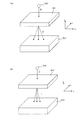
- the aspect ratio is 1 or more and less than 2, when the light parallel to the axial direction of the columnar region is irradiated, the transmitted light is isotropically diffused ⁇ see FIG. 3 (b1) ⁇ .
- the aspect ratio is 2 or more and 50 or less, when light parallel to the axial direction is irradiated in the same manner, the light diffuses with anisotropy according to the aspect ratio ⁇ see FIG. 3 (b2) ⁇ .
- the diffusion becomes more anisotropic, while when the aspect ratio is 2 or more and 20 or less, the diffusion becomes more anisotropic. It has an intermediate property between the case where the aspect ratio is 1 or more and less than 2, and the case where the aspect ratio is in the range of more than 20 and 50 or less. In this way, the range of the aspect ratio can be divided into 1 or more and less than 2, 2 or more and 20 or less, and more than 20 and less than 50, and each of them can be an anisotropic optical film having different properties.
- the composition for an anisotropic optical film according to the present invention is used as a preferable raw material in the production of an anisotropic optical film having any aspect ratio.
- the anisotropic optical film may include a plurality of columnar regions having one aspect ratio, or may include a plurality of columnar regions having different aspect ratios.
- the anisotropic optical film has a scattering center axis.
- the central axis of scattering and the orientation direction (extending direction) of the columnar region are usually in a parallel relationship. It should be noted that the fact that the central axis of scattering and the orientation direction of the columnar region are parallel does not have to be exactly parallel as long as it satisfies the law of refractive index (Snell's law).
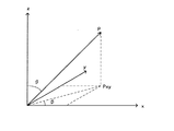
- FIG. 4 is a three-dimensional polar coordinate display for explaining the scattering center axis P in the anisotropic optical film.
- the scattering central axis coincides with the incident light angle of light whose light diffusivity is substantially symmetric with respect to the incident light angle when the incident light angle to the anisotropic optical film is changed. Means direction.
- the incident light angle at this time is a substantially central portion (central portion of the diffusion region) sandwiched between the minimum values in this optical profile (FIG. 5) by measuring the optical profile of the anisotropic optical film.
- the scattering central axis has a polar angle ⁇ , where the surface of the anisotropic optical film is the xy plane and the normal to the surface of the anisotropic optical film is the z-axis. And the azimuth angle ⁇ . That is, it can be said that Pxy in FIG. 4 is the length direction of the scattering center axis projected on the surface of the anisotropic optical film.
- the polar angle ⁇ ( ⁇ 90 ° ⁇ ⁇ 90 °) formed by the normal of the anisotropic optical film (z-axis shown in FIG. 4) and the columnar region can be defined as the scattering center axis angle. ..
- the axial angle of the columnar region can be adjusted to a desired range by changing the direction of the irradiated light beam.
- the thickness of the anisotropic optical film is not particularly limited, but is preferably 20 ⁇ m to 500 ⁇ m, more preferably 25 ⁇ m to 200 ⁇ m, and even more preferably 30 ⁇ m to 100 ⁇ m.
- the anisotropic optical film has a light diffusive incident light angle dependence in which the linear transmittance changes depending on the incident light angle.
- the curve showing the light diffusivity of the incident light angle dependence as shown in FIG. 5 is hereinafter referred to as an “optical profile”.
- optical profile can be measured as follows, for example.
- the methods described in detail in the examples can be referred to.
- an anisotropic optical film is placed between the light source 1 and the detector 2.
- the case where the irradiation light I from the light source 1 is incident from the normal direction of the anisotropic optical film is defined as an incident light angle of 0 °.
- the anisotropic optical film is arranged so that it can be arbitrarily rotated around the straight line V, and the light source 1 and the detector 2 are fixed. That is, according to this method, a sample (anisometric optical film) is arranged between the light source 1 and the detector 2, and the sample is transmitted straight through while changing the angle with the straight line V on the sample surface as the central axis. The amount of linearly transmitted light entering the detector 2 is measured.
- the optical profile does not directly express the light diffusivity, but if it is interpreted that the diffusive transmittance increases due to the decrease in the linear transmittance, it generally shows the light diffusivity. It can be said that it is.
- a normal isotropic light diffusing film shows a mountain-shaped optical profile with a peak of the incident light angle near 0 °.
- the linear transmittance is small at the incident light angle near 0 ° (-20 ° to + 20 °), and the incident light angle (of).
- a valley-shaped optical profile in which the linear transmittance increases as the absolute value) increases is shown.
- the anisotropic optical film has a property that the incident light is strongly diffused in the incident light angle range close to the scattering center axis, but the diffusion is weakened and the linear transmittance is increased in the incident light angle range beyond that. ..
- the optical profile moves so that the linear transmittance becomes smaller at the incident light angle near the scattering center axis angle (the valley of the optical profile moves to the scattering center axis angle side). do).
- the linear transmittance of light incident on the anisotropic optical film at an incident angle that minimizes the linear transmittance is referred to as the minimum linear transmittance.
- the angular range of the two incident light angles when the “minimum linear transmittance + 5%” is referred to as a diffusion region (the width of this diffusion region is the “diffusion width”), and the other incident light angles.
- the range is referred to as a non-diffusion region (transmission region).
- the linear transmittance is obtained by measuring the amount of linear transmitted light in the same manner as the measurement of the optical profile.
- the anisotropic optical film obtained by using the composition for an anisotropic optical film according to the present invention has the above diffusion width of 20 ° or more, 25 ° or more, or 35 ° or more. Can be done.
- the anisotropic optical film obtained by using the composition for an anisotropic optical film according to the present invention is sandwiched between two polarizing plates stacked so as to form a cross Nicol.
- the change in the transmittance of light leakage which is the difference between the total light transmittance in the state and the total light transmittance of the two polarizing plates, is less than 0.8%, less than 0.6%, or 0.4. It can be less than%.
- the anisotropic optical film can have a hue b * of ⁇ 2.00 or more and less than 0.55, 1.50 or more and less than 0.25, or ⁇ 1.00 or more and less than 0.00.
- Such a hue can be obtained by measuring L * a * b * (CIE1976) using a spectrophotometer (UV-2450, manufactured by Shimadzu Corporation).
- a composition for an anisotropic optical film (hereinafter, may be referred to as a "photocurable resin composition”) is applied onto an appropriate substrate such as a transparent PET film and provided in the form of a sheet to form a film. Then, a photocurable resin composition layer is provided.
- An anisotropic optical film can be produced by irradiating the photocurable resin composition layer with light after drying the photocurable resin composition layer as necessary to volatilize the solvent. ..
- the step of forming the anisotropic optical film mainly includes the following steps.
- Step 1-1 Step of providing the uncured resin composition layer on the substrate
- Step 1-2 Step of obtaining parallel light rays from a light source
- Optional step 1-3 Light rays having directivity
- a normal coating method or a printing method is applied. Specifically, air doctor coating, bar coating, blade coating, knife coating, reverse coating, transfer roll coating, gravure roll coating, kiss coating, cast coating, spray coating, slot orifice coating, calendar coating, dumb coating, dip coating. , Die coating and other coatings, intaglio printing such as gravure printing, and stencil printing such as screen printing can be used. If the composition has a low viscosity, a weir of a certain height may be provided around the substrate, and the composition may be cast in the weir surrounded by the weir.
- step 1-1 in order to prevent oxygen inhibition of the uncured resin composition layer and efficiently form columnar regions characteristic of the anisotropic optical film, the uncured resin composition layer is placed on the light irradiation side. It is also possible to stack masks that are in close contact with each other and locally change the irradiation intensity of light.
- the material of the mask is a material in which a light-absorbing filler such as carbon is dispersed in a matrix, and a part of the incident light is absorbed by carbon, but the opening is configured so that light can be sufficiently transmitted.
- a matrix includes transparent plastics such as PET, TAC, PVAC, PVA, acrylic and polyethylene, inorganic substances such as glass and quartz, and patterning and ultraviolet rays for controlling the amount of ultraviolet rays transmitted to a sheet containing these matrices. It may contain a pigment that absorbs ultraviolet rays.
- Step 1-2 Step of obtaining parallel rays from a light source>
- a short arc ultraviolet light source is usually used, and specifically, a high-pressure mercury lamp, a low-pressure mercury lamp, a metal halide lamp, a xenon lamp, or the like can be used.
- a parallel light ray for example, a point light source is arranged and the parallel light ray is generated between the point light source and the uncured resin composition layer. It can be obtained by arranging an optical lens such as a Frenel lens for irradiating, or arranging a reflecting mirror behind the light source so that light is emitted as a point light source in a predetermined direction.
- ⁇ Arbitrary step 1-3 Step to obtain a light beam with directivity>
- Optional steps 1-3 are steps in which parallel light rays are incident on a directional diffusion element to obtain directional light rays.
- FIG. 7 is a schematic view showing a method for producing an anisotropic optical film according to the present invention, which includes optional steps 1-3.
- the directivity diffusion elements 301 and 302 used in the optional steps 1-3 may be any as long as they impart directivity to the parallel light rays D incident from the light source 300.
- FIG. 7 describes that the directional light E is incident on the uncured resin composition layer 303 in a manner in which a large amount of light E is diffused in the X direction and is hardly diffused in the Y direction.
- the directional diffusion elements 301 and 302 contain a needle-shaped filler having a high aspect ratio, and the needle-shaped filler is placed in the Y direction in the long axis direction. A method of orienting the so as to persist can be adopted.
- various methods can be used in addition to the method using the needle-shaped filler.
- the aspect ratio of the directional light E is preferably 2 to 50.
- a columnar region having an aspect ratio that substantially corresponds to the aspect ratio is formed.
- the size of the columnar region to be formed (aspect ratio, minor axis SA, major axis LA, etc.) can be appropriately determined by adjusting the spread of the light E having directivity.
- the anisotropic optical film of the present embodiment can be obtained.
- the difference between FIGS. 7 (b1) and (b2) is that the spread of the directional light E is large in (b1) and small in (b2).
- the size of the columnar region differs depending on the size of the spread of the directional light E.
- the spread of the directional light E mainly depends on the types of the directional diffusion elements 301 and 302 and the distance between the uncured resin composition layer 303.
- the size of the columnar region becomes smaller as the distance is shortened, and the size of the columnar region becomes larger as the distance is lengthened. Therefore, the size of the columnar region can be adjusted by adjusting the distance.
- Step 1-4 Step of curing the uncured resin composition layer>
- the light beam that irradiates the uncured resin composition layer to cure the uncured resin composition layer needs to contain a wavelength at which the photopolymerizable compound can be cured, and is usually centered on 365 nm of a mercury lamp. Light of wavelength is used.
- an anisotropic optical film with the wavelength band preferably in the range of 0.01mW / cm 2 ⁇ 100mW / cm 2 as illuminance, 0.1mW / cm 2 ⁇ 20mW / cm 2 is more preferable.
- the light irradiation time is not particularly limited, but is preferably 10 seconds to 180 seconds, more preferably 30 seconds to 120 seconds.
- the anisotropic optical film is obtained by irradiating light with low illuminance for a relatively long time to form a specific internal structure in the uncured resin composition layer. Therefore, the unreacted monomer component may remain only by such light irradiation, causing stickiness, and there may be a problem in handleability and durability.
- the residual monomer can be polymerized by additionally irradiating light with a high illuminance of 1000 mW / cm 2 or more. The light irradiation at this time may be performed from the opposite side of the side where the masks are laminated.
- the scattering central axis of the anisotropic optical film obtained by adjusting the angle of the light applied to the uncured resin composition layer is desired. Can be.
- the anisotropic optical film may have another layer (adhesive layer, functional layer, transparent film layer, etc.).
- anisotropic optical film Since the anisotropic optical film is excellent in the effect of improving the viewing angle dependence, it can be applied to all display devices such as a liquid crystal display device, an organic EL display device, and a plasma display. Further, the anisotropic optical film can be expected to have an effect of increasing the reflection brightness in a specific direction by using it in a reflective liquid crystal display device. Since the anisotropic optical film has not only good diffusivity but also good hue, it can be expected to have an effect of improving gradation inversion by using it in a transmissive liquid crystal display device.
- the anisotropic optical film of the present invention and the anisotropic optical film of the comparative example were produced according to the following methods.
- Example 1 1. Preparation of Composition Solution 1 for Anisotropic Optical Film The composition solution 1 for anisotropic optical film was obtained by mixing and stirring the various materials shown below in the blending amounts shown below.
- (C) component polyvinyl acetate (PVAc) (refractive index: 1.460, average weight molecular weight: 200,000, glass transition temperature: 40 ° C.) 60 parts by weight
- composition 1 for Anisotropic Optical Film The obtained composition solution 1 for anisotropic optical film is applied to a PET film (manufactured by Toyobo Co., Ltd., trade name: A4300) having a thickness of 100 ⁇ m using an applicator. Then, the coating film was dried in a clean oven in which the temperature in the drying furnace was set to 80 ° C. to obtain a composition 1 for an anisotropic optical film having a film thickness of 50 ⁇ m.
- PET film manufactured by Toyobo Co., Ltd., trade name: A4300
- a polyvinyl alcohol film in which carbon is uniformly dispersed on a surface of the composition 1 for anisotropic optical film that is not in contact with the PET film (hereinafter referred to as a PVA mask).
- a PVA mask a polyvinyl alcohol film in which carbon is uniformly dispersed on a surface of the composition 1 for anisotropic optical film that is not in contact with the PET film.
- the obtained laminate is heated to 60 ° C., and while the temperature is kept constant, the parallel irradiation unit (manufactured by Hamamatsu Photonics Co., Ltd., trade name: L2859-01) for epi-illumination is emitted from above the PVA mask surface.
- the light rays were converted into linear light rays via a directional diffusion element having an aspect ratio of the light rays of 3, and irradiated at an irradiation intensity of 2.0 mW / cm 2 for 30 seconds.
- the angle of irradiating the light beam is in a direction perpendicular to each of the direction in which the light beam is diffused by the directional diffusion element and the thickness direction of the anisotropic optical film composition 1 (hereinafter referred to as the MD direction).
- the composition 1 for anisotropic optical film was irradiated in a direction inclined by 15 ° from the normal direction.
- the above-mentioned PVA mask and PET film were peeled off from the obtained laminate to obtain an anisotropic optical film 1 of Example 1.
- Example 2 The same method as in Example 1 was carried out except that the component (A) was changed to 50 parts by weight of m-phenoxybenzyl acrylate (refractive index: 1.566) to obtain an anisotropic optical film 2 of Example 2. rice field.
- Example 3 In the formulation of Example 2, the same method as in Example 1 was carried out except that the component (B) was changed to 50 parts by weight of 2-hydroxypropyl acrylate (refractive index: 1.444). An anisotropic optical film 3 was obtained.
- Example 4 In the formulation of Example 2, the same method as in Example 1 was carried out except that the component (B) was changed to 50 parts by weight of 2-acryloyloxyethyl succinate (refractive index: 1.463). Anisotropic optical film 4 of the above was obtained.
- Example 5 Anisotropy of Example 5 was carried out in the same manner as in Example 1 except that the component (B) was changed to 50 parts by weight of pentaerythritol tetraacrylate (refractive index: 1.478) in the formulation of Example 2. An anisotropic optical film 5 was obtained.
- Example 6 The same method as in Example 1 was carried out except that the blending amount of the component (A) was changed to 60 parts by weight and the blending amount of the component (B) was changed to 40 parts by weight, and the anisotropic optical film 6 of Example 6 was obtained. Obtained.
- Example 7 The same method as in Example 1 was carried out except that the blending amount of the component (A) was changed to 10 parts by weight and the blending amount of the component (B) was changed to 90 parts by weight.
- Example 8 With respect to the laminated body in which the PVA mask is laminated on the composition 1 for the anisotropic optical film, parallel light rays emitted from the epi-illumination irradiation unit are linearly transmitted through a directional diffusion element having an aspect ratio of the light rays of 50.
- An anisotropic optical film 8 of Example 8 was obtained in the same manner as in Example 1 except that it was converted into light rays and irradiated.
- Example 9 The same method as in Example 1 was carried out except that the laminated body in which the PVA mask was laminated on the composition 1 for an anisotropic optical film was directly irradiated with parallel light rays without passing through a directional diffusion element. Anisotropic optical film 9 was obtained.
- Example 10 The same method as in Example 1 was carried out except that the blending amount of the component (C) was changed to 20 parts by weight to obtain an anisotropic optical film 10 of Example 10.
- Example 11 The same method as in Example 1 was carried out except that the blending amount of the component (C) was changed to 300 parts by weight to obtain an anisotropic optical film 11 of Example 11.
- Comparative Example 1 An anisotropic optical film a of Comparative Example 1 was obtained by the same method as in Example 1 except that the amount of the component (A) to be blended was 100 parts by weight and the material to be the component (B) was not used.
- Example 2 In the blending of Example 2, the same method as in Example 1 was carried out except that the blending amount of the component (A) was 100 parts by weight and the material as the component (B) was not used, and the anisotropic optics of Comparative Example 2 was used. Film b was obtained.
- Example 3 In the formulation of Example 2, the component (B) was changed to 50 parts by weight of isostearyl acrylate (refractive index: 1.450) in the same manner as in Example 1, and the anisotropic optics of Comparative Example 3 was used. Film c was obtained.
- Comparative Example 4 The same method as in Example 1 was carried out except that the blending amount of the component (A) was changed to 90 parts by weight and the blending amount of the component (B) was changed to 10 parts by weight, and the anisotropic optical film d of Comparative Example 4 was obtained. Obtained.
- Comparative Example 5 The same method as in Example 1 was carried out except that the material (A) was not used and the blending amount of the component (B) was changed to 100 parts by weight, and the anisotropic optical film e of Comparative Example 5 was obtained. Obtained.
- Table 1 summarizes the "types and blending amounts" of the components (A) and (B) of the anisotropic optical film compositions of the above-mentioned Examples and Comparative Examples.
- the anisotropic optical film has the MD direction and the anisotropic optics. It is arranged so that it can be arbitrarily rotated about a direction orthogonal to each of the thickness directions of the film (hereinafter referred to as a TD direction) as a central axis. Subsequently, the arranged anisotropic optical films of Examples and Comparative Examples were continuously rotated in 1 ° increments in the range of ⁇ 75 ° to 75 °, and the light was transmitted in the linear direction at each incident light angle.
- the amount of light (the amount of linearly transmitted light) was measured.
- the amount of linearly transmitted light can be measured by measuring the wavelength in the visible light region using a luminosity factor filter. Then, the ratio of the amount of linearly transmitted light to the amount of linearly transmitted light (the amount of incident light, the amount of incident light) directly irradiated from the light source 1 to the detector 2 without passing through the anisotropic optical film is defined as the linear transmittance (%). bottom.
- the linear transmittance %.
- the angle range of the two incident light angles when the "minimum linear transmittance + 5%" is defined as the "diffusion width".
- the normal direction of the anisotropic optical film is 0 °
- the incident light angle is shown in the minus direction and the plus direction. Therefore, the incident light angle may have a negative value.
- the values of the two incident light angles are "a positive incident light angle value and a negative incident light angle value", "the sum of the absolute value of the negative incident light angle value and the positive incident light angle value”.
- Is the diffusion width which is the angular range of the incident light angle.
- the diffusion width which is the angular range of the incident light angles.
- the diffusion width which is the angular range of the incident light angles.
- ⁇ TT TT 1- TT 0
- the anisotropic optical film between the two polarizing plates is sandwiched between the two polarizing plates by about 5 °, so that the anisotropic optical film is formed in a circle.
- the measurement was performed for each rotated state, and ⁇ TT when the total light transmittance (TT 1 ) was the highest was defined as the change in the transmittance of light leakage.
- evaluation criteria The evaluation criteria for each evaluation of the examples of the present invention are as follows.
- “Diffusion width” ⁇ Very excellent diffusivity 35 ° or more ⁇ : Excellent diffusivity 25 ° or more and less than 35 ° ⁇ : Diffusible with no practical problem 20 ° or more and less than 25 ° ⁇ : Insufficient diffusivity There is less than 20 °
- Table 2 shows the evaluation results of the anisotropic optical film of Examples and Comparative Examples of the present invention.
- the anisotropic optical film of the present invention has a good diffusivity with a wide diffusion width, a hue, particularly a value of b * of 0.55 or less, and light between cross Nicols. It was also confirmed that there was little leakage, and it was confirmed that the anisotropic optical film could suppress the decrease in contrast when incorporated into various display devices.
- Examples 1 and 2 a monofunctional (meth) acrylate containing both a hydroxyl group and a phenyl group is used as the component (B), and the amounts of the components (A) and (B) are blended.
- the evaluation results were particularly excellent among the examples.
- Example 3 is a monofunctional (meth) acrylate having one hydroxyl group as the component (B), and Example 4 is a monofunctional (meth) acrylate having one carboxyl group as the component (B). It is an anisotropic optical film produced by using each of.
- Examples 3 and 4 although the diffusion width is slightly inferior to that in Examples 1 and 2, an anisotropic optical film having excellent diffusivity and a very excellent hue and very little light leakage can be obtained. I was able to.
- the reason why the diffusion width of Examples 3 and 4 is slightly inferior to that of Examples 1 and 2 is that the monofunctional (meth) acrylate used as the component (B) contains a phenyl group. Therefore, it is considered that this is because the difference in refractive index between the matrix region inside the anisotropic optical film and the plurality of columnar regions is small.
- Example 5 is an anisotropic optical film produced by using a polyfunctional (meth) acrylate having a plurality of (meth) acryloyl groups as the component (B), specifically, as the component (B). It is an anisotropic optical film produced by using a polyfunctional (meth) acrylate having four (meth) acryloyl groups. It is considered that the reason why the anisotropic optical film of Example 5 has a very excellent hue is that the component structure (B) suppresses the ⁇ - ⁇ stacking interaction between aromatic rings. ..
- Example 6 and Example 7 is an anisotropic optical film produced by using the same type of material as in Example 1 and changing the blending amounts of the components (A) and (B), respectively.
- Example 6 in which the blending amount of the component (A) was larger than that in Example 1, the evaluation result of the hue was slightly inferior, and in Example 7 in which the blending amount of the component (A) was reduced, the evaluation result of the diffusion width was obtained.
- the components (A) and (B) were slightly inferior to each other within the range shown in these examples, the components (A) and (B) had excellent diffusivity and sufficient hue.
- Example 8 the same kind of material as in Example 1 is used, and the blending amounts of the components (A) and (B) are also the same, but in Example 8, when produced.
- the anisotropic optical film produced in Example 9 by changing the aspect ratio of the irradiating light beam without using the directional diffusion element.
- Example 8 in which the aspect ratio of the irradiated light beam was increased, it was confirmed that the diffusion width and the evaluation result of light leakage were slightly inferior, but the light had excellent diffusivity and a very excellent hue.
- Example 9 in which parallel light rays were directly irradiated, an anisotropic optical film having very excellent diffusivity and hue and very little light leakage could be obtained.
- Example 10 In each of Example 10 and Example 11, the same kind of material as in Example 1 was used, and the amount of the component (C) to be blended with respect to the component (A) and the component (B) was changed to obtain anisotropy. It is an optical film.
- Example 10 in which the blending amount of the component (C) was smaller than that in Example 1, the evaluation results of the diffusion width, the hue, and the light leakage were slightly inferior, and the blending amount of the component (C) was increased.
- No. 11 it was confirmed that the evaluation results of the diffusion width were slightly inferior, but the amount of the component (C) to the component (A) and the component (B) within the range shown in these examples was sufficient. It was possible to obtain an anisotropic optical film having excellent diffusivity and excellent hue and having little light leakage.
- Comparative Example 1 and Comparative Example 2 are anisotropic optical films produced without using the material as the component (B), and it was confirmed that the hues were insufficient as compared with each of the examples of the present invention. Was done. Above all, the value of b * of hue was bad. Furthermore, light leakage was confirmed. This is because the component (B) is not contained, so that the structure of the anisotropic optical film is difficult to form a complicated three-dimensional structure, and the ⁇ - ⁇ stacking interaction between aromatic rings cannot be suppressed. It is thought that there is.
- Comparative Example 3 is an anisotropic optical film produced by using a monofunctional (meth) acrylate having no hydroxyl group, carboxyl group, or amino group as the component (B), and is compared with each example of the present invention. Then, the diffusivity and the hue b * were insufficient, and light leakage was confirmed. This is because the component (B) used does not have a function of making the structure of the anisotropic optical film into a complicated three-dimensional structure, and cannot suppress the ⁇ - ⁇ stacking interaction between aromatic rings. It is thought that it is doing.
- Comparative Example 4 is an anisotropic optical film produced by using the same type of material as in Example 1 so that the blending amount of the component (A) is significantly larger than the blending amount of the component (B).
- the diffusivity was excellent, the hue was insufficient b * , and light leakage was confirmed.
- the amount of the component (B) is extremely small, which makes it difficult for the anisotropic optical film to have a complicated three-dimensional structure, and the ⁇ - ⁇ stacking interaction between aromatic rings cannot be suppressed. It is thought that it is doing.
- Comparative Example 5 is an anisotropic optical film produced without using the material as the component (A), and it was confirmed that the diffusion width was insufficient as compared with each example of the present invention. It is considered that this is because the difference in refractive index between the matrix region inside the anisotropic optical film and the plurality of columnar regions is small because the component (A) is not contained.
Landscapes
- Chemical & Material Sciences (AREA)
- Physics & Mathematics (AREA)
- Health & Medical Sciences (AREA)
- Chemical Kinetics & Catalysis (AREA)
- Medicinal Chemistry (AREA)
- Polymers & Plastics (AREA)
- Organic Chemistry (AREA)
- General Physics & Mathematics (AREA)
- Optics & Photonics (AREA)
- Manufacture Of Macromolecular Shaped Articles (AREA)
Abstract
良好な拡散性と、良好な色相とを両立させることができ、更に表示装置に組み込んだ際のコントラスト低下を抑制することができる光拡散フィルムを製造するための異方性光学フィルム用組成物を提供する。本発明の異方性光学フィルム用組成物は、(A)成分[複数の芳香環並びに1つの(メタ)アクリロイル基を有する(メタ)アクリル酸エステル]と、(B)成分[(A)成分とは異なる(メタ)アクリル酸エステル]と、(C)成分[熱可塑性ポリマー]とを含む組成物であって、組成物中の(B)成分の含有量が、(A)成分の含有量を100重量部とした際に、50重量部~1000重量部であり、組成物中の(C)成分の含有量が、(A)成分及び(B)成分の含有量を100重量部とした際に、10重量部~400重量部である。
Description
本発明は、異方性光学フィルム用組成物及び異方性光学フィルム用組成物を用いて製造された異方性光学フィルムに関する。
液晶表示装置(LCD)、有機エレクトロルミネッセンス素子(有機EL)等の各種表示装置は、視野角の拡大等を目的として、異方性を有する光拡散フィルムが適用される場合がある。
このような異方性を有する光拡散フィルムを製造するための光拡散フィルム用組成物として、特許文献1には、(A)成分としての複数の芳香環を含有する(メタ)アクリル酸エステルと、(B)成分としてのウレタン(メタ)アクリレートと、(C)成分としての光重合開始剤と、(D)成分としての、特定のヒンダードアミン系光安定化剤と、を含み、(A)成分の含有量を、(B)成分100重量部に対して、25~400重量部の範囲内の値とするとともに、(C)成分の含有量を、(A)成分及び(B)成分の合計量(100重量部)に対して、0.2~20重量部の範囲内の値とし、(D)成分の含有量を、(A)成分及び(B)成分の合計量(100重量部)に対して、0.1~10重量部の範囲内の値としたものが開示されている。
上記特許文献1に開示された光拡散フィルムは、光の拡散と透過において、良好な入射角度依存性を有する、とあるものの、透明性が不十分で色味を呈している(色相のb*値が0.56以上で黄色味がかっている)。また、この光拡散フィルムは、表示装置の光学性能、特にコントラストを低下させる場合があった。
そこで本発明は、良好な拡散性と、良好な色相とを両立させることができ、更に表示装置に組み込んだ際のコントラスト低下を抑制することができる光拡散フィルムを製造するための異方性光学フィルム用組成物の提供を課題とする。
本発明者らは、上記特許文献1について詳細に検討を行い、以下の結論に達した。
特許文献1に係る光拡散フィルムは、複数の芳香環を含有する(メタ)アクリル酸エステルを使用している。このため、光硬化後の分子構造は、芳香環同士によるπ-πスタッキング相互作用が生じやすくなり、この相互作用により、π電子は、分子構造内の広い範囲に共役することが出来るようになることで、光拡散フィルムの光の吸収波長が、長波長側の可視光線の領域までシフトし、色味を呈するようになってしまうものと考えられる。
具体的には、特許文献1の段落0016では、「紫外線に長時間曝された場合であっても黄変が生じにくく」と記載されているものの、実施例の表1では、b*の初期値が「0.56以上」であり、初期値の段階で、既に黄色味を呈してしまっている。
加えて上述のような、芳香環同士によるπ-πスタッキング相互作用が生じる光拡散フィルムは、光硬化後の分子構造が特定の方向に配向しやすい状態となり、その結果、複屈折が生じて位相差を有する光拡散フィルムとなってしまうものと考えられた。更にこのような光拡散フィルムを、例えば、視野角拡大や輝度向上を目的として、液晶セルと、偏光板との間に配置する場合、偏光を乱されることにより、クロスニコル配置では光漏れ、パラレルニコル配置では光損失を招く等、表示装置の光学性能、特にコントラストを低下させる原因となってしまうものと考えられた。
上記検討等も考慮し、特定の成分を含む異方性光学フィルム用組成物が、上記課題を解決可能なことを見出した。即ち、本発明は以下の通りである。
本発明は、
(A)成分としての、複数の芳香環並びに1つの(メタ)アクリロイル基を有する(メタ)アクリル酸エステルと、
(B)成分としての、下記(b1)成分及び/又は(b2)成分であり、(A)成分とは異なる(メタ)アクリル酸エステルと、
(C)成分としての、重量平均分子量が1,000~500,000であり、且つ、ガラス転移温度が-40℃以上である熱可塑性ポリマーと
を含む組成物であって、
前記組成物中の前記(B)成分の含有量が、前記(A)成分の含有量を100重量部とした際に、50重量部~1000重量部であり、
前記組成物中の前記(C)成分の含有量が、前記(A)成分及び前記(B)成分の含有量を100重量部とした際に、10重量部~400重量部であることを特徴とする、異方性光学フィルム用組成物である。
[(b1)成分]
複数の(メタ)アクリロイル基を有する(メタ)アクリル酸エステル
[(b2)成分]
ヒドロキシル基、カルボキシル基又はアミノ基のいずれか1つ以上、並びに、1つの(メタ)アクリロイル基、を有する(メタ)アクリル酸エステル
(A)成分としての、複数の芳香環並びに1つの(メタ)アクリロイル基を有する(メタ)アクリル酸エステルと、
(B)成分としての、下記(b1)成分及び/又は(b2)成分であり、(A)成分とは異なる(メタ)アクリル酸エステルと、
(C)成分としての、重量平均分子量が1,000~500,000であり、且つ、ガラス転移温度が-40℃以上である熱可塑性ポリマーと
を含む組成物であって、
前記組成物中の前記(B)成分の含有量が、前記(A)成分の含有量を100重量部とした際に、50重量部~1000重量部であり、
前記組成物中の前記(C)成分の含有量が、前記(A)成分及び前記(B)成分の含有量を100重量部とした際に、10重量部~400重量部であることを特徴とする、異方性光学フィルム用組成物である。
[(b1)成分]
複数の(メタ)アクリロイル基を有する(メタ)アクリル酸エステル
[(b2)成分]
ヒドロキシル基、カルボキシル基又はアミノ基のいずれか1つ以上、並びに、1つの(メタ)アクリロイル基、を有する(メタ)アクリル酸エステル
前記(A)成分の屈折率が、1.5以上1.65未満であってもよい。
前記(A)成分が、ビフェニル環構造を有してもよい。
前記(A)成分が、ジフェニルエーテル構造を有してもよい。
前記(B)成分が、少なくとも一つの芳香環構造を有してもよい。
前記(C)成分の屈折率が、1.35以上1.5未満であってもよい。
前記異方性光学フィルム用組成物は、(D)成分として、光重合開始剤を含んでいてもよい。
前記(A)成分が、ビフェニル環構造を有してもよい。
前記(A)成分が、ジフェニルエーテル構造を有してもよい。
前記(B)成分が、少なくとも一つの芳香環構造を有してもよい。
前記(C)成分の屈折率が、1.35以上1.5未満であってもよい。
前記異方性光学フィルム用組成物は、(D)成分として、光重合開始剤を含んでいてもよい。
また、本発明は、
前記異方性光学フィルム用組成物の硬化物である異方性光学フィルムであって、
前記異方性光学フィルムは、光の入射角により、(入射した光の直線方向の透過光量)/(入射した光の光量)である、直線透過率が変化するフィルムであり、
前記異方性光学フィルムは、マトリックス領域と、前記マトリックス領域とは屈折率の異なる複数の柱状領域とを有することを特徴とする、異方性光学フィルムであってもよい。
前記異方性光学フィルム用組成物の硬化物である異方性光学フィルムであって、
前記異方性光学フィルムは、光の入射角により、(入射した光の直線方向の透過光量)/(入射した光の光量)である、直線透過率が変化するフィルムであり、
前記異方性光学フィルムは、マトリックス領域と、前記マトリックス領域とは屈折率の異なる複数の柱状領域とを有することを特徴とする、異方性光学フィルムであってもよい。
前記異方性光学フィルムの複数の柱状領域は、前記異方性光学フィルムの一方の表面から他方の表面にかけて配向、かつ、延在して構成されており、
前記異方性光学フィルムの柱軸に垂直な断面における、前記柱状領域の平均長径/平均短径、である前記柱状領域のアスペクト比が、1以上50以下であってもよい。
前記異方性光学フィルムの柱軸に垂直な断面における、前記柱状領域の平均長径/平均短径、である前記柱状領域のアスペクト比が、1以上50以下であってもよい。
前記異方性光学フィルムの厚さが、20μm~500μmであってもよい。
前記異方性光学フィルムの色相b*が、-2.00以上0.55未満であってもよい。
前記異方性光学フィルムにおいて、入射した光の直線透過率が最小となる入射光角度で異方性光学フィルムに入射した光の直線透過率である、最小直線透過率の値に5%を加えた直線透過率の値に対する2つの入射光角度の角度範囲が、20°以上であってもよい。
クロスニコルとなるよう重ね合わせた2枚の偏光板の間に、前記異方性光学フィルムを挟んだ状態での全光線透過率と、前記2枚の偏光板の全光線透過率との差である光漏れの透過率変化が、0.8%未満であってもよい。
前記異方性光学フィルムの色相b*が、-2.00以上0.55未満であってもよい。
前記異方性光学フィルムにおいて、入射した光の直線透過率が最小となる入射光角度で異方性光学フィルムに入射した光の直線透過率である、最小直線透過率の値に5%を加えた直線透過率の値に対する2つの入射光角度の角度範囲が、20°以上であってもよい。
クロスニコルとなるよう重ね合わせた2枚の偏光板の間に、前記異方性光学フィルムを挟んだ状態での全光線透過率と、前記2枚の偏光板の全光線透過率との差である光漏れの透過率変化が、0.8%未満であってもよい。
本発明によれば、良好な拡散性と、良好な色相とを両立させることができ、更に表示装置に組み込んだ際のコントラスト低下を抑制することができる光拡散フィルムを製造するための異方性光学フィルム用組成物を提供可能である。
本発明に係る異方性光学フィルム用組成物、及び、異方性光学フィルム用組成物を硬化して得られた異方性光学フィルム等について説明する。なお、異方性光学フィルム用組成物とは、異方性光学フィルムを製造するために用いられる組成物である。
以下の説明において、上限値と下限値とが別々に記載されている場合、上限値と下限値との全ての組み合わせが、本明細書に記載されているものとする。
本発明において、各成分の屈折率とは、JIS K0062に準拠した方法にて測定されたものを示す。
<<<異方性光学フィルム用組成物>>>
<<成分>>
本発明に係る異方性光学フィルム用組成物は、第1の(メタ)アクリル酸エステルである(A)成分、第2の(メタ)アクリル酸エステルである(B)成分、熱可塑性ポリマーである(C)成分を含む。
<<成分>>
本発明に係る異方性光学フィルム用組成物は、第1の(メタ)アクリル酸エステルである(A)成分、第2の(メタ)アクリル酸エステルである(B)成分、熱可塑性ポリマーである(C)成分を含む。
また、異方性光学フィルム用組成物は、光重合開始剤である(D)成分を含むことが好ましい。さらに、異方性光学フィルム用組成物は、その他の成分である(E)成分を含んでいてもよい。
以下、それぞれの成分について説明する。
<(A)成分:第1の(メタ)アクリル酸エステル>
(A)成分は、複数の芳香環並びに1つ(1つのみ)の(メタ)アクリロイル基を有する(メタ)アクリル酸エステルである。
(A)成分は、複数の芳香環並びに1つ(1つのみ)の(メタ)アクリロイル基を有する(メタ)アクリル酸エステルである。
(A)成分は、複数の芳香環を含む構造として、ビフェニル環構造、又は、ジフェニルエーテル構造を有していることが好ましい。このようなビフェニル構造やジフェニルエーテル構造は、骨格中に、1つのみ有してもよいし、2つ以上有していてもよい。このような構造を有することで、非常に高い屈折率を持つ(メタ)アクリル酸エステルとなる。
(A)成分は、通常、高屈折率材料である。具体的には、(A)成分の屈折率が、1.50以上であることが好ましく、1.53以上であることがより好ましく、1.56以上であることが更に好ましい。屈折率の上限としては特に限定されないが、例えば、1.65以下であることが好ましい。(A)成分の屈折率をこのような範囲とすることで、異方性光学フィルムの拡散性をより向上させることができる。
このような(A)成分としては、特に限定されないが、下記一般式(1)で表わされるビフェニル化合物、もしくは下記一般式(2)で表されるジフェニルエーテル化合物等が挙げられる。

一般式(1)中、R1~R10は、それぞれ独立しており、R1~R10のいずれか1つが、下記一般式(3)または(4)で表わされる置換基である。残りは、(メタ)アクリロイル基が含まれていなければ良く、具体的には、水素原子、ヒドロキシル基、カルボキシル基、アルキル基、アルコキシ基、ハロゲン化アルキル基、ヒドロキシアルキル基、カルボキシアルキル基およびハロゲン原子などの置換基が挙げられる。
また、一般式(2)中、R11~R20は、それぞれ独立しており、R11~R20のいずれか1つが、下記一般式(3)または(4)で表わされる置換基である。残りは、(メタ)アクリロイル基が含まれていなければ良く、具体的には、水素原子、ヒドロキシル基、カルボキシル基、アルキル基、アルコキシ基、ハロゲン化アルキル基、ヒドロキシアルキル基、カルボキシアルキル基およびハロゲン原子のなどの置換基が挙げられる。
また、一般式(2)中、R11~R20は、それぞれ独立しており、R11~R20のいずれか1つが、下記一般式(3)または(4)で表わされる置換基である。残りは、(メタ)アクリロイル基が含まれていなければ良く、具体的には、水素原子、ヒドロキシル基、カルボキシル基、アルキル基、アルコキシ基、ハロゲン化アルキル基、ヒドロキシアルキル基、カルボキシアルキル基およびハロゲン原子のなどの置換基が挙げられる。


上記一般式(3)および(4)で表わされる置換基における繰り返し数mを、通常1~10の整数とすることが好ましい。
この理由は、繰り返し数mが10を超えた値となると、(A)成分特有の芳香環に由来する屈折率の向上効果が抑制され、異方性光学フィルムの拡散性が低下する場合があるためである。
したがって、一般式(3)および(4)で表わされる置換基における繰り返し数mを、1~4の整数とすることがより好ましく、1~2の整数とすることが更に好ましい。
なお、同様の観点から、一般式(3)および(4)で表わされる置換基における炭素数nを、通常1~4の整数とすることが好ましく、1~2の整数とすることより好ましい。
この理由は、繰り返し数mが10を超えた値となると、(A)成分特有の芳香環に由来する屈折率の向上効果が抑制され、異方性光学フィルムの拡散性が低下する場合があるためである。
したがって、一般式(3)および(4)で表わされる置換基における繰り返し数mを、1~4の整数とすることがより好ましく、1~2の整数とすることが更に好ましい。
なお、同様の観点から、一般式(3)および(4)で表わされる置換基における炭素数nを、通常1~4の整数とすることが好ましく、1~2の整数とすることより好ましい。
上記一般式(1)で表わされるビフェニル化合物の具体例としては、下記式(5)で表わされる化合物を好ましく挙げることができる。
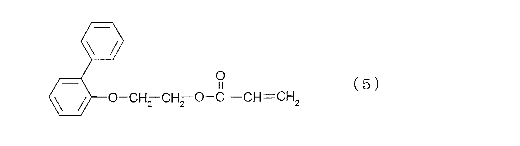
上記一般式(2)で表わされるジフェニルエーテル化合物の具体例としては、下記式(6)で表わされる化合物を好ましく挙げることができる。

(A)成分は、上述したような成分を、1種のみ含んでいてもよいし、複数種を含んでいてもよい。
<(B)成分:第2の(メタ)アクリル酸エステル>
(B)成分は、(A)成分とは異なる成分であり、(b1)成分及び/又は(b2)成分である。なお、(B)成分は、(b1)成分又は(b2)成分のいずれか一方のみであってもよいし、(b1)成分及び(b2)成分の両方を含むものであってもよい。
(B)成分は、(A)成分とは異なる成分であり、(b1)成分及び/又は(b2)成分である。なお、(B)成分は、(b1)成分又は(b2)成分のいずれか一方のみであってもよいし、(b1)成分及び(b2)成分の両方を含むものであってもよい。
(b1)成分は、複数の(メタ)アクリロイル基を有する(メタ)アクリル酸エステルである。
(b1)成分の有する(メタ)アクリロイル基の数は、特に限定されないが、光硬化後の異方性光学フィルムの可撓性を向上させるために、2~3としても良いし、光硬化後の剛直性や耐熱性を向上させるために4~6としても良い。
(b1)成分としては、特に限定されないが、例えば下記一般式(7)で表されるペンタエリスリトールテトラアクリレート等が挙げられる。

(B)成分が(b1)成分を含む場合、(A)成分を、ヒドロキシル基、カルボキシル基及びアミノ基を含まないものとしてもよい。
(b2)成分は、ヒドロキシル基、カルボキシル基又はアミノ基のいずれか1つ以上、並びに、1つ(1つのみ)の(メタ)アクリロイル基、を有する(メタ)アクリル酸エステルである。なお、(b2)成分は、ヒドロキシル基、カルボキシル基又はアミノ基を2つ以上有していてもよい。その場合、同種の官能基を2つ以上(例えば、ヒドロキシル基を2つ以上)有していてもよいし、異種の官能基を合計2つ以上(例えば、ヒドロキシル基を1つ以上、カルボキシル基を1つ以上)有していてもよい。
(b2)成分としては、特に限定されないが、例えば下記一般式(8)で表される(メタ)アクリル酸エステル等が挙げられる。
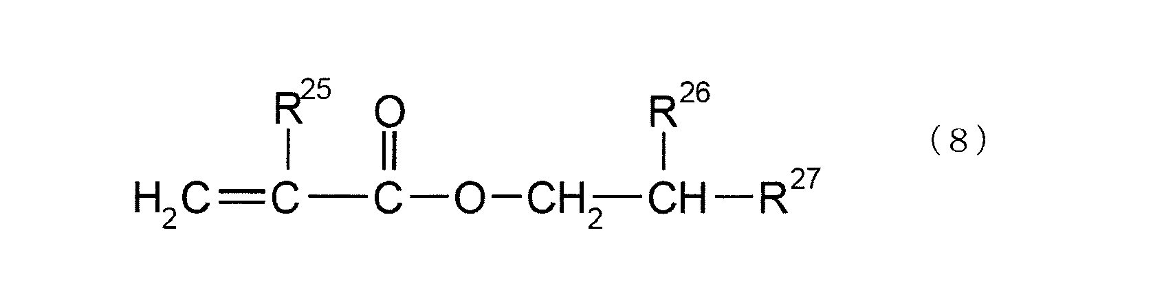
上記一般式(8)で表わされる置換基R26は、通常ヒドロキシル基、カルボキシル基又はアミノ基のいずれかである。この理由は、上記官能基を「水素結合供与体」及び「水素結合受容体」として作用させ、光硬化後の異方性光学フィルムの分子構造に水素結合を生じさせることで、複雑な3次元構造にし、(A)成分に由来する芳香環同士によるπ-πスタッキング相互作用を弱めるためである。したがって、上記水素結合の作用を強くするため、官能基R26をヒドロキシル基とすることがより好ましい。
また、置換基、R27は通常水素原子、ヒドロキシル基、カルボキシル基、アルキル基、アルコキシ基、ハロゲン化アルキル基、ヒドロキシアルキル基、カルボキシアルキル基およびハロゲン原子のいずれかの置換基であり、その中でも屈折率を高くするため芳香環を有したアルコキシ基であることがより好ましい。
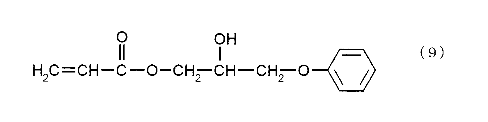
上記一般式(8)で表わされる(メタ)アクリル酸エステルの具体例としては、下記式(9)で表わされる化合物を好ましく挙げることができる。
(B)成分は、高屈折率材料であることが好ましい。屈折率の値は特に限定されないが、具体的には、1.44以上であることが好ましく、1.48以上であることがより好ましく、1.52以上であることが更に好ましい。屈折率の上限としては特に限定されないが、例えば、1.57以下であることが好ましい。(B)成分の屈折率をこのような範囲とすることで、異方性光学フィルムの拡散性をより向上させることができる。
(B)成分は、上記のように高屈折材料とするため、芳香環構造を有していることが好ましい。
(B)成分は、上述したような成分を、1種のみ含んでいてもよいし、複数種を含んでいてもよい。
異方性光学フィルムの製造においては、高屈折率材料と、低屈折率材料の屈折率差を大きくすることで、構造体の境界を際立たせ、拡散性を高めることができる。(A)成分は、高屈折率の重合性化合物として有用と考えられるが、π-πスタッキング相互作用が発生する。前述のように、このπ-πスタッキング相互作用により、色味を呈するようになってしまうものと考えられる。
そこで、(B)成分として(b1)成分を使用することで、(b1)成分に含まれる複数の(メタ)アクリロイル基によって、異方性光学フィルム用組成物の光硬化後の構造が複雑な3次元構造となり、芳香環同士によるπ-πスタッキング相互作用を生じにくくさせる。
また、(B)成分として(b2)成分を使用することで、(b2)成分が「水素結合供与体」及び「水素結合受容体」として作用するための官能基を有することとなり、異方性光学フィルム用組成物の光硬化後の異方性光学フィルムの分子構造に水素結合が入ることで、複雑な3次元構造となり、芳香環同士によるπ-πスタッキング相互作用を生じにくくさせる。このような効果を奏するための官能基として、ヒドロキシル基、カルボキシル基及びアミノ基が使用される。
<(C)成分:熱可塑性ポリマー>
(C)成分のガラス転移温度は、-40℃以上であり、0℃以上であることが好ましく、30℃以上であることがより好ましい。ガラス転移温度の上限値は特に限定されないが、例えば150℃以下であることが好ましい。
(C)成分のガラス転移温度は、-40℃以上であり、0℃以上であることが好ましく、30℃以上であることがより好ましい。ガラス転移温度の上限値は特に限定されないが、例えば150℃以下であることが好ましい。
ガラス転移温度は、公知の測定方法、例えば、JIS K7121-1987「プラスチックの転移温度測定方法」に準拠した方法により測定できる。
(C)成分の重量平均分子量は、1,000~500,000であり、10,000~400,000であることが好ましく、50,000~300,000であることが更に好ましい。
重量平均分子量は、公知の測定方法、例えば、ポリスチレン換算分子量として、GPC法を用いて測定することができる。
(C)成分のガラス転移温度および重量平均分子量を上記範囲とすることで、(A)成分および(B)成分との相溶性を高め優れた性能の異方性光学フィルムとすること、耐熱性試験等での耐久性を向上させること、UV硬化前の異方性光学フィルムに適度な弾性率を持たせロールでの保管を可能とすること、等ができる。
(C)成分は、通常、低屈折材料である。具体的には、(C)成分の屈折率が、1.50未満であることが好ましく、1.49未満であることがより好ましく、1.48未満であることが更に好ましい。屈折率の下限値は特に限定されないが、例えば1.38以上であることが好ましい。
このような(C)成分としては、特に限定されないが、例えばアクリル樹脂、スチレン樹脂、スチレン-アクリル共重合体、ポリウレタン樹脂、ポリエステル樹脂、エポキシ樹脂、セルロース系樹脂、シリコーン系樹脂、酢酸ビニル系樹脂、塩化ビニル-酢酸ビニル共重合体、ポリビニルブチラール樹脂、ポリビニルアルコール樹脂、ポリビニルホルマール樹脂、ポリビニルアセタール樹脂、ポリフッ化ビニリデン、PMMA-PBAブロック共重合体、PVdF-HFP共重合体、等が挙げられる。
(C)成分は、上述したような成分を、1種のみ含んでいてもよいし、複数種を含んでいてもよい。
このような(C)成分を配合することで、(A)成分及び(B)成分を含む高屈材料との屈折率差による相分離をしやすくでき、また、異方性光学フィルムとした際に圧痕になりにくく、貯蔵性に優れたものとすることができる。
<(D)成分:光重合開始剤>
(D)成分の光重合開始剤は、紫外線等の活性エネルギー線の照射により、ラジカル種を発生させる化合物であり、従来公知のものを使用することができる。
(D)成分の光重合開始剤は、紫外線等の活性エネルギー線の照射により、ラジカル種を発生させる化合物であり、従来公知のものを使用することができる。
光重合開始剤としては、例えば、ベンゾフェノン、ベンジル、ミヒラーズケトン、2-クロロチオキサントン、2,4-ジエチルチオキサントン、ベンゾインエチルエーテル、ベンゾインイソプロピルエーテル、ベンゾインイソブチルエーテル、2,2-ジエトキシアセトフェノン、ベンジルジメチルケタール、2,2-ジメトキシ-1,2-ジフェニルエタン-1-オン、2-ヒドロキシ-2-メチル-1-フェニルプロパン-1-オン、1-ヒドロキシシクロヘキシルフェニルケトン、2-メチル-1-[4-(メチルチオ)フェニル]-2-モルフォリノプロパノン-1、1-[4-(2-ヒドロキシエトキシ)-フェニル]-2-ヒドロキシ-2-メチル-1-プロパン-1-オン、ビス(シクロペンタジエニル)-ビス[2,6-ジフルオロ-3-(ピル-1-イル)フェニル]チタニウム、2-ベンジル-2-ジメチルアミノ-1-(4-モルフォリノフェニル)-ブタノン-1、2,4,6-トリメチルベンゾイルジフェニルフォスフィンオキサイド等が挙げられる。
これらの化合物は、各単体で用いてもよく、複数混合して用いてもよい。
光重合開始剤は、通常粉体を光重合性化合物中に直接溶解して使用しても良いが、溶解性が悪い場合は光重合開始剤を予め溶剤に溶解させたものを使用することもできる。
<(E)成分:その他の成分>
(E)成分としては、光重合性を向上させるために公知の各種染料や増感剤や、そのほかの公知の添加剤等を含んでいてもよい。
(E)成分としては、光重合性を向上させるために公知の各種染料や増感剤や、そのほかの公知の添加剤等を含んでいてもよい。
さらに、光重合性化合物を加熱により硬化させることのできる熱硬化開始剤を光重合開始剤と共に併用することもできる。この場合、光硬化の後に加熱することにより光重合性化合物の重合硬化をさらに促進し完全なものにすることが期待できる。
光重合性化合物を含む組成物を調製する際の溶剤としては、例えば、酢酸エチル、酢酸ブチル、アセトン、メチルエチルケトン、メチルイソブチルケトン、シクロヘキサノン、トルエン、キシレン等を使用することができる。
<<含有量>>
(B)成分の含有量は、(A)成分の含有量100重量部に対し、50重量部~1000重量部であり、65重量部~900重量部であることがより好ましく、75重量部~200重量部であることが更に好ましい。
(B)成分の含有量は、(A)成分の含有量100重量部に対し、50重量部~1000重量部であり、65重量部~900重量部であることがより好ましく、75重量部~200重量部であることが更に好ましい。
(C)成分の含有量は、(A)成分及び(B)成分の含有量100重量部に対し、10重量部~400重量部であり、25重量部~150重量部であることがより好ましく、40重量部~100重量部であることが更に好ましい。
(A)成分、(B)成分、(C)成分の含有量を上記のような範囲とすることで、各成分同士の相互作用を適切なものとすることができる。
組成物の全固形分(揮発性溶媒を除いた、不揮発成分の全量)に対する、(A)成分、(B)成分、(C)成分の含有量の合計は、特に限定されないが、50重量%以上、60重量%以上、70重量%以上、80重量%以上、90重量%以上、95重量%以上、99重量%以上、100重量%等とすることができる。
(D)成分の含有量は、(A)成分、(B)成分及び(C)成分の含有量100重量部に対し、0.1重量部~20重量部であることが好ましく、0.5重量部~10重量部であることがより好ましい。
本発明に係る異方性光学フィルム用組成物は、良好な拡散性と、良好な色相とを両立させることができ、更に表示装置に組み込んだ際のコントラスト低下を抑制することができる光拡散フィルムを製造することができる。次に、異方性光学フィルム用組成物を使用して得られる異方性光学フィルムの好適例について説明する。なお、異方性光学フィルム用組成物を使用すれば、下記に示す異方性光学フィルム以外の異方性光学フィルムを製造することが可能である。
<<<異方性光学フィルム>>>
異方性光学フィルムは、光の入射角により、直線透過率[(入射した光の直線方向の透過光量)/(入射した光の光量)]が変化する、光学異方性を有するフィルムである。即ち、異方性光学フィルムに対する入射光について、所定の角度範囲の入射光は直線性を維持して透過し、その他の角度範囲の入射光は、拡散性を示す。
異方性光学フィルムは、光の入射角により、直線透過率[(入射した光の直線方向の透過光量)/(入射した光の光量)]が変化する、光学異方性を有するフィルムである。即ち、異方性光学フィルムに対する入射光について、所定の角度範囲の入射光は直線性を維持して透過し、その他の角度範囲の入射光は、拡散性を示す。
例えば、図1に示される異方性光学フィルムでは、入射角が20°~50°の場合に拡散性を示し、その他の入射角では拡散性を示さず、直線透過性を示す。
<<構造>>
本発明における異方性光学フィルムは、マトリックス領域と、マトリックス領域とは屈折率の異なる複数の柱状領域とを有する。異方性光学フィルムに含まれる複数の柱状領域は、通常、異方性光学フィルムの一方の表面から他方の表面にかけて配向、かつ、延在して構成されている(図3等参照)。
本発明における異方性光学フィルムは、マトリックス領域と、マトリックス領域とは屈折率の異なる複数の柱状領域とを有する。異方性光学フィルムに含まれる複数の柱状領域は、通常、異方性光学フィルムの一方の表面から他方の表面にかけて配向、かつ、延在して構成されている(図3等参照)。
ここで、屈折率が異なるとは、異方性光学フィルムに入射した光の少なくとも一部が、マトリックス領域と、柱状領域との界面において反射が起こる程度に差異があればよく、特に限定されないが、例えば、マトリックス領域と柱状領域との屈折率の差は、0.001以上あればよい。
このようなマトリックス領域と柱状領域は、上述した各成分の相分離によって形成される。
<柱状領域>
柱状領域の長さは、特に限定されず、異方性光学フィルムの一方の表面から他方の表面に貫通したものでもよく、一方の表面から他方の表面に届かない長さでも良い。
柱状領域の長さは、特に限定されず、異方性光学フィルムの一方の表面から他方の表面に貫通したものでもよく、一方の表面から他方の表面に届かない長さでも良い。
異方性光学フィルムに含まれる複数の柱状領域の、異方性光学フィルムの表面における複数の柱状領域の表面形状は、短径と、長径とを有する形状とすることができる。
柱状領域の表面形状は、特に限定されず、例えば、円形、楕円形、多角形とすることができる。円形の場合には、短径と長径とは等しくなり、楕円形の場合には、短径は短軸の長さ、長径は長軸の長さであり、多角形の場合には、多角形内の最も短い長さを短径とし、最も長い長さを長径とすることができる。図2に、異方性光学フィルムの表面方向から見た柱状領域を示す。図2中、LAは長径を表わし、SAは短径を表わしている。
柱状領域の短径及び長径は、異方性光学フィルムの、柱軸に垂直な断面における表面を光学顕微鏡で観察し、任意に選択した20個の柱状領域についてそれぞれの短径、長径を計測し、これらの平均値とすることができる。
柱状領域の平均短径に対する平均長径の比(平均長径/平均短径)、即ち、アスペクト比は、特に限定されないが、例えば、1以上50以下とすることができる。
図2(b1)は、柱状領域のアスペクト比が2~50の異方性光学フィルムを示しており、図2(b2)は、柱状領域のアスペクト比が1以上2未満の異方性光学フィルムを示している。
アスペクト比が1以上2未満の場合には、柱状領域の軸方向に平行な光を照射した場合、その透過光は等方的に拡散する{図3(b1)を参照}。一方、アスペクト比が2以上50以下の場合には、同様に軸方向に平行な光を照射した場合には、アスペクト比に応じた異方性をもって拡散する{図3(b2)を参照}。
なお、アスペクト比を2以上50以下とした場合において、アスペクト比を20超50以下の範囲とした場合、より異方性をもった拡散となる一方で、アスペクト比が2以上20以下の場合、アスペクト比が1以上2未満の場合とアスペクト比を20超50以下の範囲とした場合との中間的な性質を有するものとなる。このように、アスペクト比の範囲を、1以上2未満、2以上20以下、20超50未満として区分し、それぞれを異なる性質を有する異方性光学フィルムとすることができる。本発明に係る異方性光学フィルム用組成物は、いずれのアスペクト比の異方性光学フィルムの製造においても、好ましい原料として使用される。
異方性光学フィルムは、1つのアスペクト比を有する複数の柱状領域を含んでもよいし、異なるアスペクト比を持つ、複数の柱状領域を含んでもよい。
<散乱中心軸>
異方性光学フィルムは、散乱中心軸を有する。散乱中心軸と柱状領域の配向方向(延在方向)とは、通常、平行な関係にある。なお、散乱中心軸と柱状領域の配向方向とが平行であるとは、屈折率の法則(Snellの法則)を満たすものであればよく、厳密に平行である必要はない。
異方性光学フィルムは、散乱中心軸を有する。散乱中心軸と柱状領域の配向方向(延在方向)とは、通常、平行な関係にある。なお、散乱中心軸と柱状領域の配向方向とが平行であるとは、屈折率の法則(Snellの法則)を満たすものであればよく、厳密に平行である必要はない。
Snellの法則は、屈折率n1の媒質から屈折率n2の媒質の界面に対して光が入射する場合、その入射光角度θ1と屈折角θ2との間に、n1sinθ1=n2sinθ2の関係が成立するものである。例えば、n1=1(空気)、n2=1.51(異方性光学フィルム)とすると、入射光角度が30°の場合、柱状領域の配向方向(屈折角)は約19°となるが、このように入射光角度と屈折角が異なっていてもSnellの法則を満たしていれば、本発明においては平行の概念に包含される。
次に、図4を参照しながら、異方性光学フィルムにおける散乱中心軸Pについてより詳細に説明する。図4は、異方性光学フィルムにおける散乱中心軸Pを説明するための3次元極座標表示である。
散乱中心軸は、上述したように、異方性光学フィルムへの入射光角度を変化させた際に光拡散性がその入射光角度を境に略対称性を有する光の入射光角度と一致する方向を意味する。なお、このときの入射光角度は、異方性光学フィルムの光学プロファイルを測定し、この光学プロファイル(図5)における極小値に挟まれた略中央部(拡散領域の中央部)となる。
散乱中心軸は、図4に示すような3次元極座標表示によれば、異方性光学フィルムの表面をxy平面とし、異方性光学フィルムの表面に対する法線をz軸とすると、極角θと方位角φとによって表現することができる。つまり、図4中のPxyが、異方性光学フィルムの表面に投影した散乱中心軸の長さ方向ということができる。
ここで、異方性光学フィルムの法線(図4に示すz軸)と、柱状領域とのなす極角θ(-90°<θ<90°)を散乱中心軸角度と定義することができる。未硬化樹脂組成物層を光硬化させ柱状領域を形成させる工程において、照射する光線の方向を変えることで、柱状領域の軸方向の角度を所望の範囲に調整することができる。
<厚さ>
異方性光学フィルムの厚さは、特に限定されないが、20μm~500μmであることが好ましく、25μm~200μmであることがより好ましく、30μm~100μmであることが更に好ましい。
異方性光学フィルムの厚さは、特に限定されないが、20μm~500μmであることが好ましく、25μm~200μmであることがより好ましく、30μm~100μmであることが更に好ましい。
<<物性>>
<光学プロファイル>
図5に示すように、異方性光学フィルムは、入射光角度によって直線透過率が変化する光拡散性の入射光角度依存性を有するものである。ここで、図5のように光拡散性の入射光角度依存性を示す曲線を以下、「光学プロファイル」と称する。
<光学プロファイル>
図5に示すように、異方性光学フィルムは、入射光角度によって直線透過率が変化する光拡散性の入射光角度依存性を有するものである。ここで、図5のように光拡散性の入射光角度依存性を示す曲線を以下、「光学プロファイル」と称する。
光学プロファイルは、例えば以下のようにして測定できる。なお、これら光学プロファイルの測定条件等は、実施例にて詳しく説明された方法を参照できる。
図6に示すように、異方性光学フィルムを光源1と検出器2との間に配置する。本形態においては、光源1からの照射光Iが、異方性光学フィルムの法線方向から入射する場合を入射光角度0°とした。また、異方性光学フィルムは直線Vを中心として、任意に回転させることができるように配置され、光源1及び検出器2は固定されている。すなわち、この方法によれば、光源1と検出器2との間にサンプル(異方性光学フィルム)を配置し、サンプル表面の直線Vを中心軸として角度を変化させながらサンプルを直進透過して検出器2に入る直線透過光量を測定する。
光学プロファイルは、光拡散性を直接的に表現しているものではないが、直線透過率が低下することで、逆に拡散透過率が増大していると解釈すれば、概ね光拡散性を示しているといえる。
通常の等方的な光拡散フィルムでは、0°付近の入射光角度をピークとする、山型の光学プロファイルを示す。
異方性光学フィルムでは、例えば、散乱中心軸角度を0°とすると(図5)、0°付近(-20°~+20°)の入射光角度で直線透過率が小さく、入射光角度(の絶対値)が大きくなるにつれて直線透過率が大きくなる谷型の光学プロファイルを示す。
このように、異方性光学フィルムは、入射光が散乱中心軸に近い入射光角度範囲では強く拡散されるが、それ以上の入射光角度範囲では拡散が弱まり直線透過率が高まるという性質を有する。
散乱中心軸角度が0°以外の場合には、散乱中心軸角度付近の入射光角度で直線透過率が小さくなるように光学プロファイルが移動する(光学プロファイルの谷部が散乱中心軸角度側に移動する)。
<直線透過率>
図5に示すように、直線透過率が最大となる入射角で異方性光学フィルムに入射した光の直線透過率を、最大直線透過率と称する。
図5に示すように、直線透過率が最大となる入射角で異方性光学フィルムに入射した光の直線透過率を、最大直線透過率と称する。
図5に示すように、直線透過率が最小となる入射角で異方性光学フィルムに入射した光の直線透過率を、最少直線透過率と称する。
図5に示すように、「最小直線透過率+5%」のときの2つの入射光角度の角度範囲を拡散領域(この拡散領域の幅を「拡散幅」)と称し、それ以外の入射光角度範囲を非拡散領域(透過領域)と称する。
直線透過率は、光学プロファイルの測定と同様にして直線透過光量を測定することにより得られる。
ここで、本発明に係る異方性光学フィルム用組成物を使用することで得られる異方性光学フィルムは、上記拡散幅を、20°以上、25°以上、又は、35°以上とすることができる。
また、本発明に係る異方性光学フィルム用組成物を使用することで得られる異方性光学フィルムは、クロスニコルとなるよう重ね合わせた2枚の偏光板の間に、異方性光学フィルムを挟んだ状態での全光線透過率と、2枚の偏光板の全光線透過率との差である光漏れの透過率変化を、0.8%未満、0.6%未満、又は、0.4%未満とすることができる。
<色相>
前記異方性光学フィルムは、色相b*を、-2.00以上0.55未満、-1.50以上0.25未満、または、-1.00以上0.00未満とすることができる。
前記異方性光学フィルムは、色相b*を、-2.00以上0.55未満、-1.50以上0.25未満、または、-1.00以上0.00未満とすることができる。
なお、このような色相は、分光光度計(島津製作所社製、UV-2450)を用いて、L*a*b*(CIE1976)を測定することで得られる。
<<異方性光学フィルムの製造方法>>
次に、異方性光学フィルム用組成物を用いた、異方性光学フィルムの製造方法について説明する。
次に、異方性光学フィルム用組成物を用いた、異方性光学フィルムの製造方法について説明する。
まず、異方性光学フィルム用組成物(以下、「光硬化樹脂組成物」と称する場合がある。)を、透明PETフィルムのような適当な基体上に塗布してシート状に設け、成膜して光硬化樹脂組成物層を設ける。この光硬化樹脂組成物層を、必要に応じて乾燥し溶剤を揮発させた上で、光硬化樹脂組成物層上に、光を照射することで、異方性光学フィルムを作製することができる。
より具体的には、異方性光学フィルムの形成工程は、主に、以下の工程を有するものである。
(1)工程1-1:未硬化樹脂組成物層を基体上に設ける工程
(2)工程1-2:光源から平行光線を得る工程
(3)任意工程1-3:指向性をもった光線を得る工程
(4)工程1-4:未硬化樹脂組成物層を硬化させる工程
(1)工程1-1:未硬化樹脂組成物層を基体上に設ける工程
(2)工程1-2:光源から平行光線を得る工程
(3)任意工程1-3:指向性をもった光線を得る工程
(4)工程1-4:未硬化樹脂組成物層を硬化させる工程
<工程1-1:未硬化樹脂組成物層を基体上に設ける工程>
光硬化樹脂組成物を、基体上に、シート状に、未硬化樹脂組成物層として設ける手法は、通常の塗工方式や印刷方式が適用される。具体的には、エアドクターコーティング、バーコーティング、ブレードコーティング、ナイフコーティング、リバースコーティング、トランスファロールコーティング、グラビアロールコーティング、キスコーティング、キャストコーティング、スプレーコーティング、スロットオリフィスコーティング、カレンダーコーティング、ダムコーティング、ディップコーティング、ダイコーティング等のコーティングや、グラビア印刷等の凹版印刷、スクリーン印刷等の孔版印刷等の印刷等が使用できる。組成物が低粘度の場合は、基体の周囲に一定の高さの堰を設けて、この堰で囲まれた中に組成物をキャストすることもできる。
光硬化樹脂組成物を、基体上に、シート状に、未硬化樹脂組成物層として設ける手法は、通常の塗工方式や印刷方式が適用される。具体的には、エアドクターコーティング、バーコーティング、ブレードコーティング、ナイフコーティング、リバースコーティング、トランスファロールコーティング、グラビアロールコーティング、キスコーティング、キャストコーティング、スプレーコーティング、スロットオリフィスコーティング、カレンダーコーティング、ダムコーティング、ディップコーティング、ダイコーティング等のコーティングや、グラビア印刷等の凹版印刷、スクリーン印刷等の孔版印刷等の印刷等が使用できる。組成物が低粘度の場合は、基体の周囲に一定の高さの堰を設けて、この堰で囲まれた中に組成物をキャストすることもできる。
工程1-1において、未硬化樹脂組成物層の酸素阻害を防止して、異方性光学フィルムの特徴である柱状領域を効率良く形成させるために、未硬化樹脂組成物層の光照射側に密着して光の照射強度を局所的に変化させるマスクを積層することも可能である。
マスクの材質としては、カーボン等の光吸収性のフィラーをマトリックス中に分散したもので、入射光の一部はカーボンに吸収されるが、開口部は光が十分に透過できるような構成のものが好ましい。このようなマトリックスとしては、PET、TAC、PVAc、PVA、アクリル、ポリエチレン等の透明プラスチックや、ガラス、石英等の無機物や、これらのマトリックスを含むシートに紫外線透過量を制御するためのパターニングや紫外線を吸収する顔料を含んだものであっても構わない。
このようなマスクを用いない場合には、窒素雰囲気下で光照射を行うことで、未硬化樹脂組成物層の酸素阻害を防止することも可能である。また、通常の透明フィルムを未硬化樹脂組成物層上に積層するだけでも、酸素阻害を防ぎ柱状領域の形成を促す上で有効である。このようなマスクや透明フィルムを介した光照射では、光重合性化合物を含む組成物中に、その照射強度に応じた光重合反応を生じるため、屈折率分布を生じ易く、本形態に係る異方性光学フィルムの作製に有効である。
<工程1-2:光源から平行光線を得る工程>
光源としては、通常はショートアークの紫外線発生光源が使用され、具体的には高圧水銀灯、低圧水銀灯、メタハライドランプ、キセノンランプ等が使用可能である。このとき、所望の散乱中心軸と平行な光線を得る必要があるが、このような平行光線は、例えば点光源を配置して、この点光源と未硬化樹脂組成物層の間に平行光線を照射するためのフレネルレンズ等の光学レンズを配置する他、光源の背後に反射鏡を配置して、所定の方向に点光源として光が出射するようにすること等で、得ることができる。
光源としては、通常はショートアークの紫外線発生光源が使用され、具体的には高圧水銀灯、低圧水銀灯、メタハライドランプ、キセノンランプ等が使用可能である。このとき、所望の散乱中心軸と平行な光線を得る必要があるが、このような平行光線は、例えば点光源を配置して、この点光源と未硬化樹脂組成物層の間に平行光線を照射するためのフレネルレンズ等の光学レンズを配置する他、光源の背後に反射鏡を配置して、所定の方向に点光源として光が出射するようにすること等で、得ることができる。
<任意工程1-3:指向性をもった光線を得る工程>
任意工程1-3は、平行光線を指向性拡散要素に入射させ、指向性をもった光線を得る工程である。図7は、任意工程1-3を含む本発明に係る異方性光学フィルムの製造方法を示す模式図である。
任意工程1-3は、平行光線を指向性拡散要素に入射させ、指向性をもった光線を得る工程である。図7は、任意工程1-3を含む本発明に係る異方性光学フィルムの製造方法を示す模式図である。
任意工程1-3で用いられる指向性拡散要素301及び302は、光源300から入射した平行光線Dに指向性を付与するものであればよい。
図7においては指向性をもった光Eが、X方向に多く拡散し、Y方向にはほとんど拡散しない態様にて、未硬化樹脂組成物層303に入射することを記載している。このように指向性をもった光を得るためには、例えば、指向性拡散要素301及び302内に、アスペクト比の高い針状フィラーを含有させるとともに、当該針状フィラーをY方向に長軸方向が延存するように配向させる方法を採用することができる。指向性拡散要素301及び302は、針状フィラーを使用する方法以外に、種々の方法を使用することができる。
ここで、指向性をもった光Eのアスペクト比は、2~50とすることが好ましい。当該アスペクト比にほぼ対応した、アスペクト比を有する柱状領域が形成される。
任意工程1-3においては、指向性をもった光Eの広がりを調整することにより、形成される柱状領域の大きさ(アスペクト比、短径SA、長径LA等)を適宜定めることができる。例えば、図7(b1)、(b2)のいずれにおいても、本形態の異方性光学フィルムを得ることができる。図7(b1)と(b2)で異なるのは、指向性をもった光Eの広がりが、(b1)では大きいのに対し(b2)では小さいことである。指向性をもった光Eの広がりの大きさに依存して、柱状領域の大きさが異なることとなる。
指向性をもった光Eの広がりは、主に指向性拡散要素301及び302の種類と、未硬化樹脂組成物層303との距離に依存する。当該距離を短くするにつれ柱状領域の大きさは小さくなり、長くするにつれ柱状領域の大きさは大きくなる。従って、当該距離を調整することにより、柱状領域の大きさを調整することができる。
<工程1-4:未硬化樹脂組成物層を硬化させる工程>
未硬化樹脂組成物層に照射して、未硬化樹脂組成物層を硬化させる光線は、光重合性化合物を硬化可能な波長を含んでいることが必要で、通常は水銀灯の365nmを中心とする波長の光が利用される。この波長帯を使って異方性光学フィルムを作製する場合、照度としては0.01mW/cm2~100mW/cm2の範囲が好ましく、0.1mW/cm2~20mW/cm2がより好ましい。照度が0.01mW/cm2未満であると、硬化に長時間を要するため、生産効率が悪くなり、100mW/cm2を超えると、光重合性化合物の硬化が速すぎて構造形成を生じず、目的の光学特性を発現できなくなるからである。
未硬化樹脂組成物層に照射して、未硬化樹脂組成物層を硬化させる光線は、光重合性化合物を硬化可能な波長を含んでいることが必要で、通常は水銀灯の365nmを中心とする波長の光が利用される。この波長帯を使って異方性光学フィルムを作製する場合、照度としては0.01mW/cm2~100mW/cm2の範囲が好ましく、0.1mW/cm2~20mW/cm2がより好ましい。照度が0.01mW/cm2未満であると、硬化に長時間を要するため、生産効率が悪くなり、100mW/cm2を超えると、光重合性化合物の硬化が速すぎて構造形成を生じず、目的の光学特性を発現できなくなるからである。
なお、光の照射時間は特に限定されないが、10秒間~180秒間が好ましく、30秒間~120秒間がより好ましい。上記光線を照射することで、本形態の異方性光学フィルムを得ることができる。
異方性光学フィルムは、上述の如く、低照度の光を比較的長時間照射することにより、未硬化樹脂組成物層中に、特定の内部構造が形成されることで得られるものである。そのため、このような光照射だけでは未反応のモノマー成分が残存して、べたつきを生じたりしてハンドリング性や耐久性に問題がある場合がある。そのような場合は、1000mW/cm2以上の高照度の光を追加照射して残存モノマーを重合させることができる。このときの光照射はマスクを積層した側の逆側から行ってもよい。
前述したように、未硬化樹脂組成物層を硬化させる際に、未硬化樹脂組成物層に照射される光の角度を調整することにより、得られる異方性光学フィルムの散乱中心軸を所望のものとすることができる。
なお、異方性光学フィルムは、さらに別の層(粘着層、機能層、透明フィルム層等)を有していてもよい。
<<異方性光学フィルムの用途>>
異方性光学フィルムは、視角依存性改善効果に優れることから、液晶表示装置、有機EL表示装置、プラズマディスプレイ等のあらゆる表示装置に適用することができる。また、異方性光学フィルムは、反射型液晶表示装置に使用することで、特定方向に対する反射輝度を高める効果が期待できる。異方性光学フィルムは、良好な拡散性に加えて、良好な色相も有するため、透過型液晶表示装置に使用することで、階調反転の改善効果も期待できる。
異方性光学フィルムは、視角依存性改善効果に優れることから、液晶表示装置、有機EL表示装置、プラズマディスプレイ等のあらゆる表示装置に適用することができる。また、異方性光学フィルムは、反射型液晶表示装置に使用することで、特定方向に対する反射輝度を高める効果が期待できる。異方性光学フィルムは、良好な拡散性に加えて、良好な色相も有するため、透過型液晶表示装置に使用することで、階調反転の改善効果も期待できる。
次に、本発明を実施例及び比較例により、更に具体的に説明するが、本発明は、これらの例によって何ら限定されるものではない。
(異方性光学フィルムの製造)
以下の方法にしたがって、本発明の異方性光学フィルム及び比較例の異方性光学フィルムを製造した。
以下の方法にしたがって、本発明の異方性光学フィルム及び比較例の異方性光学フィルムを製造した。
[実施例1]
1.異方性光学フィルム用組成物溶液1の調製
下記に示す各種材料を、それぞれ、下記に示す配合量にて、混合・攪拌を行うことにより異方性光学フィルム用組成物溶液1を得た。
1.異方性光学フィルム用組成物溶液1の調製
下記に示す各種材料を、それぞれ、下記に示す配合量にて、混合・攪拌を行うことにより異方性光学フィルム用組成物溶液1を得た。
・(A)成分:エトキシ化o-フェニルフェノールアクリレート(屈折率:1.577)
50重量部
50重量部
・(B)成分:2-ヒドロキシ-3-フェノキシプロピルアクリレート(屈折率:1.520)
50重量部
50重量部
・(C)成分:ポリビニルアセテート(PVAc)(屈折率:1.460、平均重量分子量:200000、ガラス転移温度:40℃)
60重量部
60重量部
・(D)成分:2、2-ジメトキシ-2-フェニルアセトフェノン
2重量部
2重量部
・溶媒:酢酸ブチル
150重量部
150重量部
2.異方性光学フィルム用組成物1の作製
得られた異方性光学フィルム用組成物溶液1を、厚さ100μmのPETフィルム(東洋紡社製、商品名:A4300)に対し、アプリケーターを用いて塗布し、その後乾燥炉内温度を80℃に設定したクリーンオーブン内で、この塗膜を乾燥させることにより、膜厚50μmの異方性光学フィルム用組成物1を得た。
得られた異方性光学フィルム用組成物溶液1を、厚さ100μmのPETフィルム(東洋紡社製、商品名:A4300)に対し、アプリケーターを用いて塗布し、その後乾燥炉内温度を80℃に設定したクリーンオーブン内で、この塗膜を乾燥させることにより、膜厚50μmの異方性光学フィルム用組成物1を得た。
3.異方性光学フィルム1の作製
次に、異方性光学フィルム用組成物1のPETフィルムとは接していない面に対し、カーボンを均一に分散させたポリビニルアルコール膜(以下、PVAマスクと称する)を、ラミネーターを用いて積層させた。得られた積層体を60℃に加熱し、温度を一定に保った状態にて、PVAマスク面の上から落射用照射ユニット(浜松ホトニクス社製、商品名:L2859-01)から出射される平行光線を、その光線のアスペクト比が3となる指向性拡散要素を介して線状光線に変換し、照射強度2.0mW/cm2にて30秒間照射した。この際、光線を照射する角度は、指向性拡散要素で光線が拡散される方向と、異方性光学フィルム用組成物1の厚み方向とのそれぞれに直行する方向(以下MD方向と称す)に、異方性光学フィルム用組成物1の法線方向から15°傾けた方向にて、照射した。
得られた積層体から、上述のPVAマスク及びPETフィルムを剥がし、実施例1の異方性光学フィルム1を得た。
次に、異方性光学フィルム用組成物1のPETフィルムとは接していない面に対し、カーボンを均一に分散させたポリビニルアルコール膜(以下、PVAマスクと称する)を、ラミネーターを用いて積層させた。得られた積層体を60℃に加熱し、温度を一定に保った状態にて、PVAマスク面の上から落射用照射ユニット(浜松ホトニクス社製、商品名:L2859-01)から出射される平行光線を、その光線のアスペクト比が3となる指向性拡散要素を介して線状光線に変換し、照射強度2.0mW/cm2にて30秒間照射した。この際、光線を照射する角度は、指向性拡散要素で光線が拡散される方向と、異方性光学フィルム用組成物1の厚み方向とのそれぞれに直行する方向(以下MD方向と称す)に、異方性光学フィルム用組成物1の法線方向から15°傾けた方向にて、照射した。
得られた積層体から、上述のPVAマスク及びPETフィルムを剥がし、実施例1の異方性光学フィルム1を得た。
[実施例2]
(A)成分を、m-フェノキシベンジルアクリレート(屈折率:1.566)50重量部に変更したこと以外は実施例1と同様の方法で行い、実施例2の異方性光学フィルム2を得た。
(A)成分を、m-フェノキシベンジルアクリレート(屈折率:1.566)50重量部に変更したこと以外は実施例1と同様の方法で行い、実施例2の異方性光学フィルム2を得た。
[実施例3]
実施例2の配合で、(B)成分を、2-ヒドロキシプロピルアクリレート(屈折率:1.444)50重量部に変更したこと以外は実施例1と同様の方法で行い、実施例3の異方性光学フィルム3を得た。
実施例2の配合で、(B)成分を、2-ヒドロキシプロピルアクリレート(屈折率:1.444)50重量部に変更したこと以外は実施例1と同様の方法で行い、実施例3の異方性光学フィルム3を得た。
[実施例4]
実施例2の配合で、(B)成分を、2-アクリロイルオキシエチルサクシネート(屈折率:1.463)50重量部に変更したこと以外は実施例1と同様の方法で行い、実施例4の異方性光学フィルム4を得た。
[実施例5]
実施例2の配合で、(B)成分を、ペンタエリスリトールテトラアクリレート(屈折率:1.478)50重量部に変更したこと以外は実施例1と同様の方法で行い、実施例5の異方性光学フィルム5を得た。
実施例2の配合で、(B)成分を、2-アクリロイルオキシエチルサクシネート(屈折率:1.463)50重量部に変更したこと以外は実施例1と同様の方法で行い、実施例4の異方性光学フィルム4を得た。
[実施例5]
実施例2の配合で、(B)成分を、ペンタエリスリトールテトラアクリレート(屈折率:1.478)50重量部に変更したこと以外は実施例1と同様の方法で行い、実施例5の異方性光学フィルム5を得た。
[実施例6]
(A)成分の配合量を60重量部、(B)成分の配合量を40重量部に変更したこと以外は実施例1と同様の方法で行い、実施例6の異方性光学フィルム6を得た。
(A)成分の配合量を60重量部、(B)成分の配合量を40重量部に変更したこと以外は実施例1と同様の方法で行い、実施例6の異方性光学フィルム6を得た。
[実施例7]
(A)成分の配合量を10重量部、(B)成分の配合量を、90重量部に変更したこと以外は実施例1と同様の方法で行い、実施例7の異方性光学フィルム7を得た。
(A)成分の配合量を10重量部、(B)成分の配合量を、90重量部に変更したこと以外は実施例1と同様の方法で行い、実施例7の異方性光学フィルム7を得た。
[実施例8]
異方性光学フィルム用組成物1にPVAマスク積層させた積層体に対し、落射用照射ユニットから出射される平行光線を、その光線のアスペクト比が50となる指向性拡散要素を介して線状光線に変換して照射したこと以外は実施例1と同様の方法で行い、実施例8の異方性光学フィルム8を得た。
異方性光学フィルム用組成物1にPVAマスク積層させた積層体に対し、落射用照射ユニットから出射される平行光線を、その光線のアスペクト比が50となる指向性拡散要素を介して線状光線に変換して照射したこと以外は実施例1と同様の方法で行い、実施例8の異方性光学フィルム8を得た。
[実施例9]
異方性光学フィルム用組成物1にPVAマスク積層させた積層体に対し、指向性拡散要素を介さずに平行光線を直接照射したこと以外は実施例1と同様の方法で行い、実施例9の異方性光学フィルム9を得た。
[実施例10]
(C)成分の配合量を20重量部に変更したこと以外は実施例1と同様の方法で行い、実施例10の異方性光学フィルム10を得た。
[実施例11]
(C)成分の配合量を300重量部に変更したこと以外は実施例1と同様の方法で行い、実施例11の異方性光学フィルム11を得た。
異方性光学フィルム用組成物1にPVAマスク積層させた積層体に対し、指向性拡散要素を介さずに平行光線を直接照射したこと以外は実施例1と同様の方法で行い、実施例9の異方性光学フィルム9を得た。
[実施例10]
(C)成分の配合量を20重量部に変更したこと以外は実施例1と同様の方法で行い、実施例10の異方性光学フィルム10を得た。
[実施例11]
(C)成分の配合量を300重量部に変更したこと以外は実施例1と同様の方法で行い、実施例11の異方性光学フィルム11を得た。
[比較例1]
(A)成分の配合量を100重量部、(B)成分となる材料を使用しないこと以外は実施例1と同様の方法で行い、比較例1の異方性光学フィルムaを得た。
(A)成分の配合量を100重量部、(B)成分となる材料を使用しないこと以外は実施例1と同様の方法で行い、比較例1の異方性光学フィルムaを得た。
[比較例2]
実施例2の配合で、(A)成分の配合量を100重量部、(B)成分となる材料を使用しないこと以外は実施例1と同様の方法で行い、比較例2の異方性光学フィルムbを得た。
実施例2の配合で、(A)成分の配合量を100重量部、(B)成分となる材料を使用しないこと以外は実施例1と同様の方法で行い、比較例2の異方性光学フィルムbを得た。
[比較例3]
実施例2の配合で、(B)成分を、イソステアリルアクリレート 屈折率:1.450)50重量部に変更したこと以外は実施例1と同様の方法で行い、比較例3の異方性光学フィルムcを得た。
実施例2の配合で、(B)成分を、イソステアリルアクリレート 屈折率:1.450)50重量部に変更したこと以外は実施例1と同様の方法で行い、比較例3の異方性光学フィルムcを得た。
[比較例4]
(A)成分の配合量を90重量部、(B)成分の配合量を10重量部に変更したこと以外は実施例1と同様の方法で行い、比較例4の異方性光学フィルムdを得た。
(A)成分の配合量を90重量部、(B)成分の配合量を10重量部に変更したこと以外は実施例1と同様の方法で行い、比較例4の異方性光学フィルムdを得た。
[比較例5]
(A)成分となる材料を使用せず、(B)成分の配合量を100重量部に変更したこと以外は実施例1と同様の方法で行い、比較例5の異方性光学フィルムeを得た。
(A)成分となる材料を使用せず、(B)成分の配合量を100重量部に変更したこと以外は実施例1と同様の方法で行い、比較例5の異方性光学フィルムeを得た。
上述の実施例及び比較例の異方性光学フィルム用組成物の(A)成分及び(B)成分の「種類及び配合量」をまとめ、表1に示す。

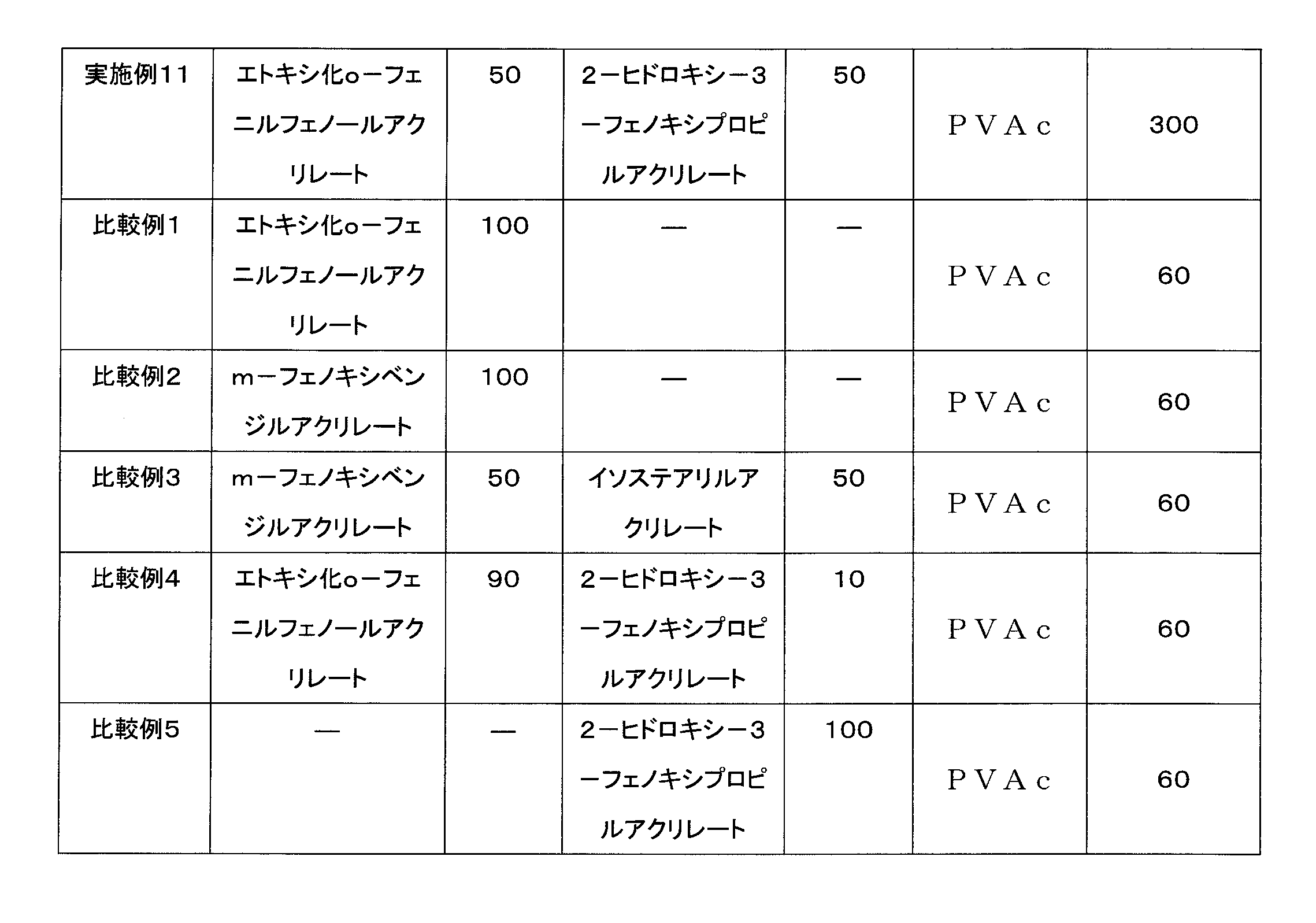
(評価方法)
上述のようにして製造した本発明実施例及び比較例の異方性光学フィルムに対し、以下評価を行った。
上述のようにして製造した本発明実施例及び比較例の異方性光学フィルムに対し、以下評価を行った。
[光拡散性の評価]
図6に示すような、光源の投光角、検出器の受光角を任意に可変できる変角光度計ゴニオフォトメータ(ジェネシア社製)を用いて、実施例及び比較例の異方性光学フィルムの光拡散性の評価を行った。図6に示すように、実施例及び比較例の異方性光学フィルムのサンプル3を、光源1と検出器2との間に配置した(ここで、光源1と検出器2は、それぞれ固定しておく)。本評価においては、光源1からの照射光Iが、異方性光学フィルムの法線方向から入射する場合を入射角度0°とし、異方性光学フィルムは、上記MD方向と、異方性光学フィルムの厚み方向とのそれぞれに直行する方向(以下TD方向と称す)を中心軸として任意に回転させることができるよう配置した。
続いて、配置した実施例及び比較例の異方性光学フィルムを、-75°~75°の範囲において、1°刻みで連続的に回転させ、それぞれの入射光角度における光の直線方向の透過光量(直線透過光量)を測定した。尚、直線透過光量の測定は、視感度フィルターを用いて可視光領域の波長を測定することにより得られる。そして、異方性光学フィルムを介さず、光源1から検出器2に直接照射される直線透過光量(入射した光の光量、入射光量)に対する直線透過光量の割合を、直線透過率(%)とした。
以上のような測定の結果、得られたデータにより光学プロファイルが得られ、この光学プロファイルに基づき、直線透過率の最大値(最大直線透過率)及び最小値(最小直線透過率)を求めた。
この際、光学プロファイルにおいて、「最小直線透過率+5%」のときの2つの入射光角度の角度範囲を「拡散幅」と定義した。
ここで、光学プロファイルにおいては、異方性光学フィルムの法線方向を0°とし、入射光角度をマイナス方向及びプラス方向で示している。したがって、入射光角度はマイナスの値を有する場合がある。
2つの入射光角度の値が、「プラスの入射光角度値及びマイナスの入射光角度値」である場合、「マイナスの入射光角度値の絶対値と、プラスの入射光角度値との和」が、入射光角度の角度範囲である拡散幅とした。
2つの入射光角度の値が「共にプラス」である場合、「より大きい値からより小さい値を引いた差」が、入射光角度の角度範囲である拡散幅とした。
2つの入射光角度の値が「共にマイナス」である場合、「それぞれの絶対値をとり、より大きい値からより小さい値を引いた差」が、入射光角度の角度範囲である拡散幅とした。
図6に示すような、光源の投光角、検出器の受光角を任意に可変できる変角光度計ゴニオフォトメータ(ジェネシア社製)を用いて、実施例及び比較例の異方性光学フィルムの光拡散性の評価を行った。図6に示すように、実施例及び比較例の異方性光学フィルムのサンプル3を、光源1と検出器2との間に配置した(ここで、光源1と検出器2は、それぞれ固定しておく)。本評価においては、光源1からの照射光Iが、異方性光学フィルムの法線方向から入射する場合を入射角度0°とし、異方性光学フィルムは、上記MD方向と、異方性光学フィルムの厚み方向とのそれぞれに直行する方向(以下TD方向と称す)を中心軸として任意に回転させることができるよう配置した。
続いて、配置した実施例及び比較例の異方性光学フィルムを、-75°~75°の範囲において、1°刻みで連続的に回転させ、それぞれの入射光角度における光の直線方向の透過光量(直線透過光量)を測定した。尚、直線透過光量の測定は、視感度フィルターを用いて可視光領域の波長を測定することにより得られる。そして、異方性光学フィルムを介さず、光源1から検出器2に直接照射される直線透過光量(入射した光の光量、入射光量)に対する直線透過光量の割合を、直線透過率(%)とした。
以上のような測定の結果、得られたデータにより光学プロファイルが得られ、この光学プロファイルに基づき、直線透過率の最大値(最大直線透過率)及び最小値(最小直線透過率)を求めた。
この際、光学プロファイルにおいて、「最小直線透過率+5%」のときの2つの入射光角度の角度範囲を「拡散幅」と定義した。
ここで、光学プロファイルにおいては、異方性光学フィルムの法線方向を0°とし、入射光角度をマイナス方向及びプラス方向で示している。したがって、入射光角度はマイナスの値を有する場合がある。
2つの入射光角度の値が、「プラスの入射光角度値及びマイナスの入射光角度値」である場合、「マイナスの入射光角度値の絶対値と、プラスの入射光角度値との和」が、入射光角度の角度範囲である拡散幅とした。
2つの入射光角度の値が「共にプラス」である場合、「より大きい値からより小さい値を引いた差」が、入射光角度の角度範囲である拡散幅とした。
2つの入射光角度の値が「共にマイナス」である場合、「それぞれの絶対値をとり、より大きい値からより小さい値を引いた差」が、入射光角度の角度範囲である拡散幅とした。
[色相の評価]
分光光度計(島津製作所社製、UV-2450)を用いて、実施例及び比較例の異方性光学フィルムのL*a*b*(CIE1976)を測定した。
分光光度計(島津製作所社製、UV-2450)を用いて、実施例及び比較例の異方性光学フィルムのL*a*b*(CIE1976)を測定した。
[異方性光学フィルムのクロスニコル間での光漏れ評価]
2枚の偏光板を用意し、クロスニコルになるように重ね合わせ、その間に実施例及び比較例の異方性学フィルムを挟んだ。
続いて光漏れを定量的に評価するため、日本電色工業社製ヘイズメーター、NDH-2000を用い、異方性光学フィルムを挟まないクロスニコル偏光板での全光線透過率( TT0)を基準として、異方性光学フィルムを挟んだ状態での全光線透過率(TT1)を測定し、その差を光漏れの透過率変化(ΔTT=TT1-TT0)として評価した。なお、この際、2枚の偏光板間の異方性光学フィルムのみを、約5°ずつ、2枚の偏光板間で挟まれた状態の異方性光学フィルムが、円を描いていくような状態にて、回転させた状態毎の測定を行い、最も全光線透過率(TT1)が高くなるときのΔTTを、光漏れの透過率変化とした。
2枚の偏光板を用意し、クロスニコルになるように重ね合わせ、その間に実施例及び比較例の異方性学フィルムを挟んだ。
続いて光漏れを定量的に評価するため、日本電色工業社製ヘイズメーター、NDH-2000を用い、異方性光学フィルムを挟まないクロスニコル偏光板での全光線透過率( TT0)を基準として、異方性光学フィルムを挟んだ状態での全光線透過率(TT1)を測定し、その差を光漏れの透過率変化(ΔTT=TT1-TT0)として評価した。なお、この際、2枚の偏光板間の異方性光学フィルムのみを、約5°ずつ、2枚の偏光板間で挟まれた状態の異方性光学フィルムが、円を描いていくような状態にて、回転させた状態毎の測定を行い、最も全光線透過率(TT1)が高くなるときのΔTTを、光漏れの透過率変化とした。
[評価基準]
本発明実施例の各評価の評価基準は以下の通りである。
本発明実施例の各評価の評価基準は以下の通りである。
「拡散幅」
◎:拡散性がとても優れている 35°以上
〇:拡散性が優れている 25°以上35°未満
△:実用上問題ない拡散性である 20°以上25°未満
×:不十分な拡散性である 20°未満
◎:拡散性がとても優れている 35°以上
〇:拡散性が優れている 25°以上35°未満
△:実用上問題ない拡散性である 20°以上25°未満
×:不十分な拡散性である 20°未満
「色相 L*」
◎:とても優れている 95以上
〇:優れている 90以上95未満
△:十分である 80以上90未満
×:不十分である 80未満
◎:とても優れている 95以上
〇:優れている 90以上95未満
△:十分である 80以上90未満
×:不十分である 80未満
「色相 a*」
◎:とても優れている -0.50以上0.50未満
〇:優れている -1.00以上-0.50未満又は0.50以上1.00未満
△:十分である -2.00以上-1.00未満又は1.00以上2.00未満
×:不十分である -2.00未満又は2.00以上
◎:とても優れている -0.50以上0.50未満
〇:優れている -1.00以上-0.50未満又は0.50以上1.00未満
△:十分である -2.00以上-1.00未満又は1.00以上2.00未満
×:不十分である -2.00未満又は2.00以上
「色相 b*」
◎:とても優れている -1.00以上0.00未満
〇:優れている -1.50以上-1.00未満又は0.00以上0.25未満
△:十分である -2.00以上-1.50未満又は0.25以上0.55未満
×:不十分である -2.00未満又は0.55以上
◎:とても優れている -1.00以上0.00未満
〇:優れている -1.50以上-1.00未満又は0.00以上0.25未満
△:十分である -2.00以上-1.50未満又は0.25以上0.55未満
×:不十分である -2.00未満又は0.55以上
「光漏れの透過率変化 ΔTT」
◎:光漏れがとても少ない 0.0%以上0.4%未満
〇:光漏れが少ない 0.4%以上0.6%未満
△:光漏れは実用上問題ない 0.6%以上0.8%未満
×:光漏れがある 0.8%以上
◎:光漏れがとても少ない 0.0%以上0.4%未満
〇:光漏れが少ない 0.4%以上0.6%未満
△:光漏れは実用上問題ない 0.6%以上0.8%未満
×:光漏れがある 0.8%以上
[アスペクト比の評価]
実施例及び比較例の異方性学フィルムの表面(製造時の紫外線照射側)を、光学顕微鏡で観察し、任意の20個の柱状領域の径(径又は長径及び短径)を測定し、各々の平均値を算出した後、算出された径に基づき、アスペクト比(長径及び短径を有する場合には、平均長径/平均短径、径のみの場合には1とする)を算出した。
実施例及び比較例の異方性学フィルムの表面(製造時の紫外線照射側)を、光学顕微鏡で観察し、任意の20個の柱状領域の径(径又は長径及び短径)を測定し、各々の平均値を算出した後、算出された径に基づき、アスペクト比(長径及び短径を有する場合には、平均長径/平均短径、径のみの場合には1とする)を算出した。
本発明実施例及び比較例の異方性光学フィルム評価結果を、表2に示す。
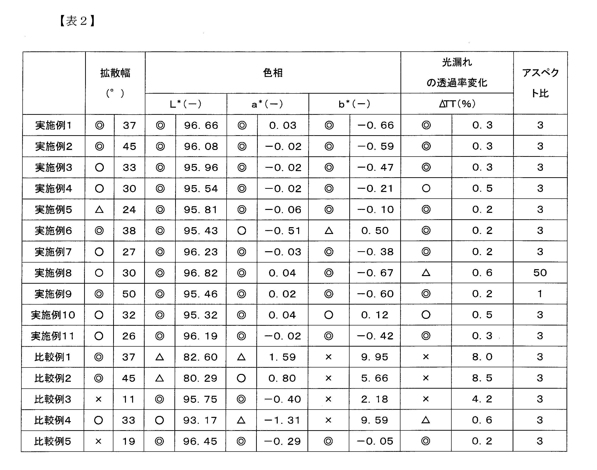
表2の実施例より、本発明異方性光学フィルムは、広い拡散幅を有する良好な拡散性に加え、色相、特にb*の値が0.55以下であり、さらにクロスニコル間での光漏れが少ないことも確認され、各種表示装置に組み込んだ際のコントラスト低下を抑制できる異方性光学フィルムであることが確認された。
特に、実施例1及び実施例2は、(B)成分として、ヒドロキシル基とフェニル基を共に含有する単官能(メタ)アクリレートを使用し、かつ、(A)成分及び(B)成分の配合量が最適であるため、実施例の中でも特に優れた評価結果となった。
実施例3は、(B)成分として、1つのヒドロキシル基を有する単官能(メタ)アクリレートを、そして、実施例4は、(B)成分として、1つのカルボキシル基を有する単官能(メタ)アクリレートをそれぞれ使用して作製した異方性光学フィルムである。
実施例3及び4では、実施例1及び2と比較し、拡散幅が若干劣るものの、優れた拡散性と、とても優れた色相とを有し、光漏れがとても少ない異方性光学フィルムを得ることができた。
ここで実施例3及び4が、実施例1及び2と比較し、拡散幅が若干劣ることとなった原因は、(B)成分として使用した単官能(メタ)アクリレートにフェニル基が含まれていないため、異方性光学フィルム内部のマトリックス領域と、複数の柱状領域との屈折率差が小さくなったことに起因しているものと考えられる。
実施例3及び4では、実施例1及び2と比較し、拡散幅が若干劣るものの、優れた拡散性と、とても優れた色相とを有し、光漏れがとても少ない異方性光学フィルムを得ることができた。
ここで実施例3及び4が、実施例1及び2と比較し、拡散幅が若干劣ることとなった原因は、(B)成分として使用した単官能(メタ)アクリレートにフェニル基が含まれていないため、異方性光学フィルム内部のマトリックス領域と、複数の柱状領域との屈折率差が小さくなったことに起因しているものと考えられる。
実施例5は、(B)成分として、複数の(メタ)アクリロイル基を有する多官能(メタ)アクリレートを使用して作製した異方性光学フィルムであり、具体的には(B)成分として、4つの(メタ)アクリロイル基を有する多官能(メタ)アクリレートを使用して作製した異方性光学フィルムである。
実施例5の異方性光学フィルムが、とても優れた色相を有する原因は、(B)成分構造が、芳香環同士によるπ-πスタッキング相互作用を抑制することに起因しているものと考えられる。
実施例5の異方性光学フィルムが、とても優れた色相を有する原因は、(B)成分構造が、芳香環同士によるπ-πスタッキング相互作用を抑制することに起因しているものと考えられる。
実施例6及び実施例7は、いずれも実施例1と同じ種類の材料を使用し、(A)成分と(B)成分の配合量をそれぞれ変更して作製した異方性光学フィルムである。
実施例1と比較して(A)成分の配合量を多くした実施例6では、色相の評価結果が若干劣り、(A)成分の配合量を少なくした実施例7では、拡散幅の評価結果が若干劣ることがそれぞれ確認されたが、これら実施例に示された範囲内での(A)成分と(B)成分の配合量であれば、優れた拡散性と、十分な色相とを有し、光漏れがとても少ない異方性光学フィルムを得ることができた。
実施例1と比較して(A)成分の配合量を多くした実施例6では、色相の評価結果が若干劣り、(A)成分の配合量を少なくした実施例7では、拡散幅の評価結果が若干劣ることがそれぞれ確認されたが、これら実施例に示された範囲内での(A)成分と(B)成分の配合量であれば、優れた拡散性と、十分な色相とを有し、光漏れがとても少ない異方性光学フィルムを得ることができた。
実施例8及び実施例9は、いずれも実施例1と同じ種類の材料を使用し、かつ、(A)成分と(B)成分の配合量も同じであるが、実施例8では製造する際、照射する光線のアスペクト比を変更し、実施例9では指向性拡散要素を使用せずに作製した異方性光学フィルムである。
照射する光線のアスペクト比を大きくした実施例8では、拡散幅と、光漏れの評価結果とが若干劣ることが確認されたが、優れた拡散性と、とても優れた色相とを有し、光漏れが実用上問題ない異方性光学フィルムを得ることができた。
平行光線を直接照射した実施例9では、とても優れた拡散性及び色相を有し、光漏れもとても少ない異方性光学フィルムを得ることができた。
照射する光線のアスペクト比を大きくした実施例8では、拡散幅と、光漏れの評価結果とが若干劣ることが確認されたが、優れた拡散性と、とても優れた色相とを有し、光漏れが実用上問題ない異方性光学フィルムを得ることができた。
平行光線を直接照射した実施例9では、とても優れた拡散性及び色相を有し、光漏れもとても少ない異方性光学フィルムを得ることができた。
実施例10及び実施例11は、いずれも実施例1と同じ種類の材料を使用し、(A)成分と(B)成分に対する(C)成分の配合量をそれぞれ変更して作製した異方性光学フィルムである。
実施例1と比較して(C)成分の配合量を少なくした実施例10では、拡散幅と、色相と、光漏れの評価結果が若干劣り、(C)成分の配合量を多くした実施例11では、拡散幅の評価結果が若干劣ることがそれぞれ確認されたが、これら実施例に示された範囲内での(A)成分と(B)成分に対する(C)成分の配合量であれば、優れた拡散性と、優れた色相とを有し、光漏れが少ない異方性光学フィルムを得ることができた。
実施例1と比較して(C)成分の配合量を少なくした実施例10では、拡散幅と、色相と、光漏れの評価結果が若干劣り、(C)成分の配合量を多くした実施例11では、拡散幅の評価結果が若干劣ることがそれぞれ確認されたが、これら実施例に示された範囲内での(A)成分と(B)成分に対する(C)成分の配合量であれば、優れた拡散性と、優れた色相とを有し、光漏れが少ない異方性光学フィルムを得ることができた。
比較例1及び比較例2は、(B)成分となる材料を使用せず作製した異方性光学フィルムであり、本発明の各実施例と比較して、不十分な色相であることが確認された。中でも色相のb*の値が悪かった。更に、光漏れが確認された。これは、(B)成分が含まれていないため、異方性光学フィルムの構造が複雑な3次元構造を取りにくくなり、芳香環同士によるπ-πスタッキング相互作用を抑制できないことに起因しているものと考えられる。
比較例3は、(B)成分としてヒドロキシル基、カルボキシル基、アミノ基を有さない単官能(メタ)アクリレートを使用して作製した異方性光学フィルムであり、本発明の各実施例と比較して、拡散性と、色相のb*とが不十分であり、光漏れが確認された。これは、使用した(B)成分が、異方性光学フィルムの構造を複雑な3次元構造にする機能を有しておらず、芳香環同士によるπ-πスタッキング相互作用を抑制できないことに起因しているものと考えられる。
比較例4は実施例1と同じ種類の材料を使用し、(B)成分の配合量と比較して(A)成分の配合量が大幅に多くなるようにして作製した異方性光学フィルムであり、本発明の各実施例と比較して、拡散性は優れているものの、不十分な色相のb*であり、光漏れが確認された。
これは、(B)成分の配合量が極めて少ないために、異方性光学フィルムの構造が複雑な3次元構造を取りにくくなり、芳香環同士によるπ-πスタッキング相互作用を抑制できないことに起因しているものと考えられる。
これは、(B)成分の配合量が極めて少ないために、異方性光学フィルムの構造が複雑な3次元構造を取りにくくなり、芳香環同士によるπ-πスタッキング相互作用を抑制できないことに起因しているものと考えられる。
比較例5は、(A)成分となる材料を使用せず作製した異方性光学フィルムであり、本発明の各実施例と比較して、不十分な拡散幅であることが確認された。これは、(A)成分が含まれていないために、異方性光学フィルム内部のマトリックス領域と、複数の柱状領域との屈折率差が小さくなったことに起因しているものと考えられる。
実施例評価結果より、本発明の異方性光学フィルム用組成物は、光硬化させて異方性光学フィルムとすると、広い拡散幅を有する良好な拡散性に加え、色相、特にb*の値が0.55以下であるため、表示装置等の用途に良好な色相を有し、さらに、クロスニコル間での光漏れが少ないことも確認され、各種表示装置に組み込んだ際のコントラスト低下を抑制可能な異方性光学フィルムとすることができることが分かった。
以上、図面を参照しながら本発明の好適な実施の形態について説明したが、本発明は上述した形態に限定されない。すなわち、特許請求の範囲に記載された発明の範囲内で当業者が想到し得る他の形態又は各種の変更例についても本発明の技術的範囲に属するものと理解される。
Claims (13)
- (A)成分としての、複数の芳香環並びに1つの(メタ)アクリロイル基を有する(メタ)アクリル酸エステルと、
(B)成分としての、下記(b1)成分及び/又は(b2)成分であり、(A)成分とは異なる(メタ)アクリル酸エステルと、
(C)成分としての、重量平均分子量が1,000~500,000であり、且つ、ガラス転移温度が-40℃以上である熱可塑性ポリマーと
を含む組成物であって、
前記組成物中の前記(B)成分の含有量が、前記(A)成分の含有量を100重量部とした際に、50重量部~1000重量部であり、
前記組成物中の前記(C)成分の含有量が、前記(A)成分及び前記(B)成分の含有量を100重量部とした際に、10重量部~400重量部であることを特徴とする、異方性光学フィルム用組成物。
[(b1)成分]
複数の(メタ)アクリロイル基を有する(メタ)アクリル酸エステル
[(b2)成分]
ヒドロキシル基、カルボキシル基又はアミノ基のいずれか1つ以上、並びに、1つの(メタ)アクリロイル基、を有する(メタ)アクリル酸エステル - 前記(A)成分の屈折率が、1.5以上1.65未満であることを特徴とする、請求項1に記載の異方性光学フィルム用組成物。
- 前記(A)成分が、ビフェニル環構造を有することを特徴とする、請求項1又は2に記載の異方性光学フィルム用組成物。
- 前記(A)成分が、ジフェニルエーテル構造を有することを特徴とする、請求項1又は2に記載の異方性光学フィルム用組成物。
- 前記(B)成分が、少なくとも一つの芳香環構造を有していることを特徴とする、請求項1~4のいずれか一項に記載の異方性光学フィルム用組成物。
- 前記(C)成分の屈折率が、1.35以上1.5未満であることを特徴とする、請求項1~5のいずれか一項に記載の異方性光学フィルム用組成物。
- (D)成分として、光重合開始剤を含むことを特徴とする、請求項1~6のいずれか一項に記載の異方性光学フィルム用組成物。
- 請求項1~7のいずれか一項に記載の異方性光学フィルム用組成物の硬化物である異方性光学フィルムであって、
前記異方性光学フィルムは、光の入射角により、(入射した光の直線方向の透過光量)/(入射した光の光量)である、直線透過率が変化するフィルムであり、
前記異方性光学フィルムは、マトリックス領域と、前記マトリックス領域とは屈折率の異なる複数の柱状領域とを有することを特徴とする、異方性光学フィルム。 - 前記異方性光学フィルムの複数の柱状領域は、前記異方性光学フィルムの一方の表面から他方の表面にかけて配向、かつ、延在して構成されており、
前記異方性光学フィルムの柱軸に垂直な断面における、前記柱状領域の平均長径/平均短径、である前記柱状領域のアスペクト比が、1以上50以下であることを特徴とする、請求項8に記載の異方性光学フィルム。 - 前記異方性光学フィルムの厚さが、20μm~500μmであることを特徴とする、請求項8又は9に記載の異方性光学フィルム。
- 前記異方性光学フィルムの色相b*が、-2.00以上0.55未満であることを特徴とする、請求項8~10のいずれか一項に記載の異方性光学フィルム。
- 前記異方性光学フィルムにおいて、入射した光の直線透過率が最小となる入射光角度で異方性光学フィルムに入射した光の直線透過率である、最小直線透過率の値に5%を加えた直線透過率の値に対する2つの入射光角度の角度範囲が、20°以上であることを特徴とする、請求項8~11のいずれか一項に記載の異方性光学フィルム。
- クロスニコルとなるよう重ね合わせた2枚の偏光板の間に、前記異方性光学フィルムを挟んだ状態での全光線透過率と、前記2枚の偏光板の全光線透過率との差である光漏れの透過率変化が、0.8%未満であることを特徴とする、請求項8~12のいずれか一項に記載の異方性光学フィルム。
Priority Applications (1)
| Application Number | Priority Date | Filing Date | Title |
|---|---|---|---|
| JP2022508429A JPWO2021187555A1 (ja) | 2020-03-19 | 2021-03-18 |
Applications Claiming Priority (2)
| Application Number | Priority Date | Filing Date | Title |
|---|---|---|---|
| JP2020049790 | 2020-03-19 | ||
| JP2020-049790 | 2020-03-19 |
Publications (1)
| Publication Number | Publication Date |
|---|---|
| WO2021187555A1 true WO2021187555A1 (ja) | 2021-09-23 |
Family
ID=77771006
Family Applications (1)
| Application Number | Title | Priority Date | Filing Date |
|---|---|---|---|
| PCT/JP2021/011056 Ceased WO2021187555A1 (ja) | 2020-03-19 | 2021-03-18 | 異方性光学フィルム用組成物及び異方性光学フィルム |
Country Status (2)
| Country | Link |
|---|---|
| JP (1) | JPWO2021187555A1 (ja) |
| WO (1) | WO2021187555A1 (ja) |
Citations (6)
| Publication number | Priority date | Publication date | Assignee | Title |
|---|---|---|---|---|
| JPH0339314A (ja) * | 1989-06-27 | 1991-02-20 | Borden Inc | 放射線硬化可能なマトリックス材料、該材料を含む光ファイバリボン及び該光ファイバリボンの調製方法 |
| JP2013205468A (ja) * | 2012-03-27 | 2013-10-07 | Tomoegawa Paper Co Ltd | 異方性光学フィルム |
| WO2014156303A1 (ja) * | 2013-03-28 | 2014-10-02 | リンテック株式会社 | 光拡散フィルム用組成物および光拡散フィルム |
| US20160223732A1 (en) * | 2015-02-04 | 2016-08-04 | Lg Electronics Inc. | Light conversion member, and backlight unit and display device including the same |
| JP2019179204A (ja) * | 2018-03-30 | 2019-10-17 | 株式会社巴川製紙所 | 異方性光学フィルム |
| JP2019179203A (ja) * | 2018-03-30 | 2019-10-17 | 株式会社巴川製紙所 | 異方性光学フィルム |
Family Cites Families (3)
| Publication number | Priority date | Publication date | Assignee | Title |
|---|---|---|---|---|
| JP7028660B2 (ja) * | 2018-01-30 | 2022-03-02 | 日東電工株式会社 | 粘着シートおよびその製造方法、ならびに粘着性フィルム |
| JP7241465B2 (ja) * | 2018-01-30 | 2023-03-17 | 日東電工株式会社 | 粘着剤、硬化性粘着剤組成物、粘着シートおよびその製造方法 |
| JP7040959B2 (ja) * | 2018-02-21 | 2022-03-23 | リンテック株式会社 | 光拡散粘着剤組成物、光拡散粘着剤シート、及び光拡散粘着剤シートの製造方法 |
-
2021
- 2021-03-18 WO PCT/JP2021/011056 patent/WO2021187555A1/ja not_active Ceased
- 2021-03-18 JP JP2022508429A patent/JPWO2021187555A1/ja active Pending
Patent Citations (6)
| Publication number | Priority date | Publication date | Assignee | Title |
|---|---|---|---|---|
| JPH0339314A (ja) * | 1989-06-27 | 1991-02-20 | Borden Inc | 放射線硬化可能なマトリックス材料、該材料を含む光ファイバリボン及び該光ファイバリボンの調製方法 |
| JP2013205468A (ja) * | 2012-03-27 | 2013-10-07 | Tomoegawa Paper Co Ltd | 異方性光学フィルム |
| WO2014156303A1 (ja) * | 2013-03-28 | 2014-10-02 | リンテック株式会社 | 光拡散フィルム用組成物および光拡散フィルム |
| US20160223732A1 (en) * | 2015-02-04 | 2016-08-04 | Lg Electronics Inc. | Light conversion member, and backlight unit and display device including the same |
| JP2019179204A (ja) * | 2018-03-30 | 2019-10-17 | 株式会社巴川製紙所 | 異方性光学フィルム |
| JP2019179203A (ja) * | 2018-03-30 | 2019-10-17 | 株式会社巴川製紙所 | 異方性光学フィルム |
Also Published As
| Publication number | Publication date |
|---|---|
| JPWO2021187555A1 (ja) | 2021-09-23 |
| TW202200629A (zh) | 2022-01-01 |
Similar Documents
| Publication | Publication Date | Title |
|---|---|---|
| US9989678B2 (en) | Anisotropic optical film | |
| JP6230670B2 (ja) | 異方性光拡散フィルム用組成物および異方性光拡散フィルム | |
| JP6616921B1 (ja) | ヘッドマウントディスプレイ | |
| JP6039911B2 (ja) | 偏光板用異方性光学フィルムおよびその製造方法 | |
| JP7475333B2 (ja) | 異方性光学フィルムを用いた反射型表示装置 | |
| JP7092962B1 (ja) | 異方性光学フィルム用組成物及び異方性光学フィルム | |
| TWI898099B (zh) | 各向異性光學膜用組成物及各向異性光學膜 | |
| WO2021187555A1 (ja) | 異方性光学フィルム用組成物及び異方性光学フィルム | |
| WO2022209566A1 (ja) | 異方性光拡散フィルム及び表示装置 | |
| TWI913253B (zh) | 異方性光學膜用組成物及異方性光學膜 | |
| JP7191537B2 (ja) | 異方性光学フィルム | |
| JP6581329B1 (ja) | ヘッドマウントディスプレイ | |
| JP2021162733A (ja) | 異方性光拡散フィルム積層体および表示装置 | |
| JP7667679B2 (ja) | 異方性光拡散フィルム積層体及び表示装置 | |
| WO2025229973A1 (ja) | 異方性光拡散フィルムとそれを用いたディスプレイ用フィルム及びディスプレイ | |
| WO2025229974A1 (ja) | 異方性光拡散フィルムとそれを用いたディスプレイ用フィルム及びディスプレイ | |
| JP7620619B2 (ja) | 異方性光拡散フィルムおよび表示装置 | |
| WO2019220775A1 (ja) | ヘッドマウントディスプレイ | |
| WO2025229972A1 (ja) | 異方性光拡散フィルムとそれを用いたディスプレイ用フィルム及びディスプレイ | |
| WO2022209567A1 (ja) | 異方性光拡散フィルムおよび表示装置 | |
| WO2025069526A1 (ja) | 拡散フィルムおよび光拡散装置 | |
| WO2023190664A1 (ja) | 液晶表示装置用偏光板積層体、及び、液晶表示装置 |
Legal Events
| Date | Code | Title | Description |
|---|---|---|---|
| 121 | Ep: the epo has been informed by wipo that ep was designated in this application |
Ref document number: 21771361 Country of ref document: EP Kind code of ref document: A1 |
|
| ENP | Entry into the national phase |
Ref document number: 2022508429 Country of ref document: JP Kind code of ref document: A |
|
| NENP | Non-entry into the national phase |
Ref country code: DE |
|
| 122 | Ep: pct application non-entry in european phase |
Ref document number: 21771361 Country of ref document: EP Kind code of ref document: A1 |