WO2021187538A1 - 緊急システム - Google Patents
緊急システム Download PDFInfo
- Publication number
- WO2021187538A1 WO2021187538A1 PCT/JP2021/010892 JP2021010892W WO2021187538A1 WO 2021187538 A1 WO2021187538 A1 WO 2021187538A1 JP 2021010892 W JP2021010892 W JP 2021010892W WO 2021187538 A1 WO2021187538 A1 WO 2021187538A1
- Authority
- WO
- WIPO (PCT)
- Prior art keywords
- emergency response
- emergency
- abnormality
- information
- unit
- Prior art date
Links
Images


Classifications
-
- E—FIXED CONSTRUCTIONS
- E05—LOCKS; KEYS; WINDOW OR DOOR FITTINGS; SAFES
- E05B—LOCKS; ACCESSORIES THEREFOR; HANDCUFFS
- E05B47/00—Operating or controlling locks or other fastening devices by electric or magnetic means
-
- E—FIXED CONSTRUCTIONS
- E05—LOCKS; KEYS; WINDOW OR DOOR FITTINGS; SAFES
- E05B—LOCKS; ACCESSORIES THEREFOR; HANDCUFFS
- E05B65/00—Locks or fastenings for special use
- E05B65/10—Locks or fastenings for special use for panic or emergency doors
-
- G—PHYSICS
- G08—SIGNALLING
- G08B—SIGNALLING OR CALLING SYSTEMS; ORDER TELEGRAPHS; ALARM SYSTEMS
- G08B21/00—Alarms responsive to a single specified undesired or abnormal condition and not otherwise provided for
- G08B21/02—Alarms for ensuring the safety of persons
-
- G—PHYSICS
- G08—SIGNALLING
- G08B—SIGNALLING OR CALLING SYSTEMS; ORDER TELEGRAPHS; ALARM SYSTEMS
- G08B25/00—Alarm systems in which the location of the alarm condition is signalled to a central station, e.g. fire or police telegraphic systems
- G08B25/01—Alarm systems in which the location of the alarm condition is signalled to a central station, e.g. fire or police telegraphic systems characterised by the transmission medium
- G08B25/04—Alarm systems in which the location of the alarm condition is signalled to a central station, e.g. fire or police telegraphic systems characterised by the transmission medium using a single signalling line, e.g. in a closed loop
-
- H—ELECTRICITY
- H04—ELECTRIC COMMUNICATION TECHNIQUE
- H04N—PICTORIAL COMMUNICATION, e.g. TELEVISION
- H04N7/00—Television systems
- H04N7/18—Closed-circuit television [CCTV] systems, i.e. systems in which the video signal is not broadcast
Definitions
- the present invention relates to an emergency system capable of promptly protecting and first-aid the elderly when an abnormality occurs in an elderly person's single-family house or the like.
- Patent Document 1 In recent years, home security systems for the purpose of crime prevention and security in homes have been widely used in ordinary households (for example, Patent Document 1).
- sensors and cameras for detecting or photographing the state of the house are installed in various parts of the house, and when the sensors react, the inside of the house is photographed by the camera, and the photographed image is included. Notify the user's mobile processing terminal of the occurrence of an abnormality. Then, the user can determine the occurrence of an abnormality by looking at the captured image displayed on the mobile processing terminal.
- Patent Document 1 since the technology disclosed in Patent Document 1 merely notifies the presence or absence of an abnormality, it is immediately necessary when an emergency occurs, for example, when an abnormality occurs in an elderly person's solitary house. There was a problem that it could not be dealt with.
- an object of the present invention is to provide a system capable of promptly responding to an urgent abnormal situation such as when an abnormality occurs in an elderly person living alone. ..
- the present invention comprises a storage means having an opening / closing means, a locking driving means for locking or unlocking the opening / closing means, and a receiving means for receiving an emergency signal notifying that an abnormality has been detected.
- a control means for driving the locking driving means to unlock the opening / closing means in response to the reception of an emergency signal is provided.
- a notification means provided outside the storage means to notify an abnormality notified by an emergency signal by light emission, acoustic output, or information display, and to be directed outward outside the storage means. It is preferable to further include a photographing means attached to the outside and a display means attached to the outside of the storage means and displaying an image captured by the photographing means. Further, in the above invention, the storage means is installed outside the building, and inside the building, a detection means for detecting an abnormality in the building and a transmission means for transmitting an emergency signal for notifying the abnormality detected by the detection means are further provided. It is preferable to prepare.
- a storage means having an opening / closing means is installed outside the building, a key for unlocking the entrance to the building is stored in the storage means, and the locking driving means opens / closes with the key stored.
- the notification means provided on the outside of the storage means notifies the abnormality notified by the emergency signal by light emission, acoustic output or information display, and is attached to the outside of the storage means toward the outside. It is preferable to further include a step in which the image captured by the photographing means is displayed by the display means attached to the outside of the storage means.
- the storage means is formed inside the wall and has an opening on the side surface of the wall body leading to the internal storage space
- the opening / closing means is a plate arranged parallel to the side surface so as to cover the opening.
- the locking driving means is a member, and the locking driving means includes a fixing means for fixing an end portion of a rod member projecting from the back surface of a plate member and penetrating the wall body to the back surface side of the wall body in a state of penetrating the wall body.
- the control means preferably unlocks by releasing the fixing by the fixing means.
- the storage means is first installed outside the building, and the key for unlocking the entrance to the building is stored in the storage means.
- the lock driving means of the storage means is driven to unlock the opening / closing means, so the person who rushes for emergency should take out the key in the storage means. Therefore, it is possible to quickly enter the building and carry out emergency activities, and it is possible to quickly respond to an urgent abnormal situation such as when an abnormality occurs in an elderly person's single-family house.
- a warning light, a speaker, a display, etc. provided outside the storage means are used to notify the neighbors and surrounding residents of the occurrence of the abnormality by emitting light, acoustic output, or information display. , It is possible to promptly inform the occurrence of an abnormality and prompt a prompt response.
- the imaging means on the display which is attached to the outer front surface of the storage means, the image is positioned in front of the device when an emergency occurs. It is possible to take a picture of the person who made the picture and display it on the display as it is, and it is possible to expect a psychological effect that it is possible to strongly encourage prompt emergency activities by making it impossible to pretend to be unnoticed or unseen.
- the emergency response system for example, when an abnormality occurs in a building 8 such as a solitary house for the elderly, notifies the neighborhood of the abnormality that has occurred, and also uses a communication means to notify a guardian or a relationship. It is a mechanism to notify people.
- the emergency response device 1 installed on the outer wall surface of the building 8, each surveillance camera / detection device 9 installed in various places in the building, and the communication network 5
- the management server 2 that is installed and can communicate with the emergency response device 1 and each surveillance camera / detection device 9, the user terminal 3 owned by the family, guardians, and other related parties of the resident of the building 8, the security company, etc. It is provided with a related organization server 4 to be managed.
- the communication network 5 includes a wireless communication network, and uses the communication protocol TCP / IP to mutually connect various communication lines (telephone line, ISDN line, ADSL line, public line such as optical line, dedicated line, wireless communication network). It is a distributed communication network constructed by connecting, and the communication network 5 includes an intranet (internal network) such as 10BASE-T and 100BASE-TX, a LAN such as a home network, and the like.
- intranet internal network
- the wireless base station 6 is a device that is connected to a communication network 5 through a relay device 7, establishes a wireless communication connection with a user terminal 3 and an emergency response device 1, and provides a call or data communication.
- the radio base station 6 in the present embodiment functions as a position information acquisition unit that manages which cell each user terminal 3 is located in on the communication network 5.
- the relay device 7 is a node device such as a modem, a terminal adapter, or a gateway device for connecting to the communication network 5, selects a communication path, performs mutual conversion of data (signals), and communicates with the radio base station 6. Relay processing with the network 5 is performed.
- the relay device 7 also includes functions of a Wi-Fi (registered trademark) router and an access point device installed in the house or outside, and wirelessly communicates with the user terminal 3 and the emergency response device 1.
- the relay device 7 automatically connects to the emergency response device 1 in the connection area of the relay device 7, each surveillance camera / detection device 9, and the user terminal 3 used by a guardian or the like.
- connection processing function that performs connection processing, and acquires the connection protocol of the information processing terminal using the connection protocol during the connection processing.
- the connection protocol is various data used at the time of connection processing, and includes a user identifier and authentication information that identifies an information processing terminal.
- the user terminal 3 is a terminal owned by a family member, a guardian, or other related persons of a resident of the building 8, and is an information processing terminal having a calculation processing function by a CPU and a communication processing function by a communication interface.
- mobile phone terminals such as smartphones
- it can be realized by general-purpose computers such as personal computers, dedicated devices with specialized functions, mobile computers and PDA (Personal Digital Assistance).
- PDA Personal Digital Assistance
- This user terminal 3 has a communication function such as wireless communication with the wireless base station 6 and a function of executing an application.
- Examples of the communication method of this mobile phone include 5G, LTE (Long Term Evolution), 3G, FDMA method, TDMA method, CDMA method, W-CDMA, PHS (Personal Handyphone System) method, and the like. ..
- a wireless communication interface different from the above-mentioned communication method it also has a function corresponding to a communication method by sending and receiving IP packets conforming to a wireless LAN standard or the like.
- the user terminal 3 is equipped with functions such as a digital camera function, an application software execution function, and a GPS function.
- the emergency response device 1 is a device that is communicably connected to the management server 2 and is installed in each user's house.
- This emergency response device 1 is provided with a calculation processing function by a CPU and a communication processing function by a communication interface, extracts a person's face from an image captured by a camera or the like, and identifies a specific individual from the face. It is equipped with a face identification function.
- the emergency response device 1 includes a key box 12 having an opening / closing lid 12a, a locking / unlocking drive unit 11 for locking or unlocking the opening / closing lid 12a, a communication function, and a communication function.
- It includes a control unit 110 having a calculation function and various output devices for alarms.
- the emergency response device 1 is provided with various notification means provided outside the housing of the emergency response device 1 to notify an abnormality notified by an emergency signal by light emission, acoustic output, or information display.
- the emergency response device 1 includes a CCD camera 13 attached to the outside of the housing toward the outside (here, the front side front side) and an outside side of the emergency response device 1 (here, the front side side). It is further provided with a display display 16 which is attached toward the front) and displays an image captured by the CCD camera 13.
- surveillance cameras and various sensors are installed indoors and outdoors. Sensors, temperature sensors, etc.) are installed.
- a wearable sensor pulse sensor, thermometer, acceleration sensor, GPS, etc.
- a bed sensor 92 installed on the bed to detect body movement at bedtime, carbon dioxide and odor in the room.
- An odor sensor 94 or the like that detects the above is used. The detection data by these various sensors is transmitted to the emergency response device 1 and the server and collected.
- the surveillance camera is a photographing device that captures a still image or a moving image, is arranged in a certain direction, and continuously photographs the surroundings inside and outside the building. Further, the surveillance camera may be capable of photographing the surroundings in a certain range by rotating the rotary table, or may use, for example, an omnidirectional camera.
- the image data or the moving image data captured by the surveillance camera is input to the emergency response device 1 via wireless communication.
- the management server 2 is a server device operated by the system provider, and manages the emergency response device 1, the surveillance camera, and various sensors installed in each home, and from the emergency response device 1, the surveillance camera, and various sensors. Accumulate various data to be transmitted. Further, the management server 2 is composed of a group of servers including a plurality of devices whose functions are distributed, such as a Web server, an application server, and a database server.
- the related organization server 4 is an information processing device provided in a security company or a related organization related to crime such as the police.
- the related organizations include, for example, convenience stores and family restaurants, as well as facilities that are open 24 hours a day and have staff resident.
- the related organization server 4 acquires a report from the emergency response device 1 or the user terminal 3 by telephone or data communication.
- the emergency response device 1 has a key box 12 having an opening / closing lid 12a, a locking / unlocking drive unit 11 for locking or unlocking the opening / closing lid 12a, and a communication function. It is provided with a control unit 110 having a calculation function and various output devices for alarms. Further, the emergency response device 1 is provided with various notification means provided outside the housing of the emergency response device 1 to notify an abnormality notified by an emergency signal by light emission, acoustic output, or information display.
- the emergency response device 1 includes a CCD camera 13 attached to the outside of the housing toward the outside (here, the front side front side) and an outside side of the emergency response device 1 (here, the front side side). It is further provided with a display display 16 which is attached toward the front) and displays an image captured by the CCD camera 13.
- the emergency response device 1 is provided on the outside of the housing of the emergency response device 1 and is provided with various notification means for notifying an abnormality notified by an emergency signal by light emission, acoustic output, or information display. Further, the emergency response device 1 includes a CCD camera 13 attached to the outside of the housing toward the outside (here, the front side front side) and an outside side of the emergency response device 1 (here, the front side side). It is further provided with a display display 16 which is attached toward the front) and displays an image captured by the CCD camera 13.
- the opening / closing lid 12a is rotatably supported by a shaft 12b horizontally arranged along the front surface of the box body 1, and is rotated about the shaft 12b. It is designed to open and close.
- the key box 12 is opened by rotating the rotary lid 12a by 90 °, and the key 81 stored inside can be taken out.
- the key 81 is suspended from the upper surface of the inside and stored.
- the opening / closing lid 12a is unlocked. For example, when a neighboring resident N tries to take out the key 81 inside the key box 12, the neighboring resident N rotates the opening / closing lid 12a by 90 ° to form a gap.
- the emergency response device 1 includes a wireless interface 101, an input interface 104, an output interface 102, a control unit 110, and a recording unit 103.
- the wireless interface 101 is an interface for two-way wireless communication, and executes wireless communication using a data communication protocol such as a wireless LAN.
- the wireless interface for data communication may be, for example, a transmitter / receiver conforming to IEEE 802.11b for making a wireless LAN connection.
- This wireless interface can be realized by a wireless LAN adapter or the like.
- the wireless interface 101 transmits the image taken by the CCD camera 13 and the sound acquired by the microphone 104a to the management server 2 via the relay device 7.
- the wireless interface 101 has a connection processing unit 101a.
- the connection processing unit 101a is a module for establishing a communication connection with the relay device 7 via wireless communication, and is a relay device 7 to which a connection protocol (including an identifier for identifying the own device) is connected. Send to and authenticate.
- the connection processing unit 101a monitors the wireless signal and identifies the relay device 7 in order to establish a link for transmitting / receiving data. May be detected.
- the relay device 7 when the relay device 7 performs connection processing with the surveillance camera / detection device 9 or the user terminal 3 in the building 8 and acquires the connection protocol, the relay device 7 is also connected to the surveillance camera / detection device 9 or the user terminal 3. Communication becomes possible.
- the input interface 104 is a device that acquires images and sounds, and the input interface includes a microphone 104a that acquires sounds such as voice, and a CCD camera 13 that is a photographing device that captures still images or moving images. There is.
- the CCD camera 13 is a photographing device installed in front of the emergency response device 1 and arranged side by side with the display display 16, and the photographing direction can be changed by a driving means.
- the input interface 104 can also acquire image data taken by the surveillance camera / detection device 9 installed in the building 8 and various detected detection data via the communication network in the house. ing.
- the output interface 102 is a device that outputs light, video, and sound.
- the output interface 102 includes a display unit 102b such as a display display 16 arranged in front of the emergency response device 1, and a speaker 102a that outputs sounds such as music, sound effects, alarms, and voices. ..
- the recording unit 103 is a storage device that stores an OS (Operating System), programs for various applications, a device ID that identifies the emergency response device 1, other data, and the like.
- the recording unit 103 stores criminal information (criminal name, image data such as face and body shape, etc.) acquired from the management server 2.
- Information on criminals can be obtained from information provided by related organizations such as the police, criminal information for each region by local governments, and publicly available information.
- a resident registers a specific person as a stalker, information about that person (name, gender, face image, voice, name, telephone number, email address, as well as email history sent to the user terminal) Information, incoming call history information, etc.) are recorded. This stalker information can be reported to the related organization server 4 and the management server 2 by user operation.
- the control unit 110 is a module that executes an application such as a general OS or browser software, and is usually realized by a CPU or the like. In addition to the voice dialogue function and the object recognition function, the control unit 110 realizes, for example, an emotion recognition function that analyzes a person's facial expression and voice tone to estimate a person's emotions. Further, in the present embodiment, the control unit 110 is provided with an image recognition unit 111, an acoustic analysis unit 112, a collation unit 113, a notification unit 114, and a drive control unit 115 as a module group related to the emergency response function. ing.
- the drive control unit 115 is a module that controls the drive of the moving means, and controls the moving means based on detection signals from various sensors (not shown) to move the emergency response device 1 forward, backward, and turn. ..
- the image recognition unit 111 is a module for identifying a person in an image acquired from the CCD camera 13.
- the image recognition unit 111 recognizes the face of the person by analyzing the contour portion of the face in the acquired image using the face recognition technique.
- the face recognition technique is a technique for extracting the contour part of the face as a feature point, and is based on eigenface using principal component analysis, linear discriminant analysis, elastic bunch graph matching, hidden Markov model, and neuron motivation.
- Various techniques can be used for dynamic link matching and the like.
- the image recognition unit 111 may acquire physical information including physical features such as a body shape from the image and recognize a feature portion other than the face.
- the image recognition unit 111 has a function of identifying an acquaintance, a resident, and an external person, and by collating data such as acquaintance information, resident information, and external person information stored in the storage unit 103. , It is designed to identify the person.
- this acquaintance information information on a legitimate visitor such as a resident or an acquaintance is associated with and accumulated in the device ID that identifies the emergency response device 1.
- the acquaintance information includes personal information of the person (name, nickname, etc., gender, age, etc.), information about the user terminal possessed by each person (telephone number, e-mail address, connection protocol, etc.), and personal characteristics.
- Data face data (including positional relationship and contour information of eyes, nose, and lips), physique information, voice data, action sounds such as footsteps, etc. are recorded.
- behavior pattern information residence such as time zone information when going out, time zone information at home, resident's position information and flow line information in the house, and the operation of locking and unlocking the entrance.
- the behavior pattern of the person, the frequency of appearance in each camera, etc. are recorded.
- behavior pattern information regarding an external human being the appearance frequency such as the number of visits, the visit time zone information, the dialogue contents with the resident collected by the input interface 104 of the emergency response device 1, the voice recognition information, and the like are recorded. Further, the external person information is recorded in association with the detected position information of the detected camera / sensor.
- This detected position information is a place and time at which a person is identified, and includes position information and time information such as a kitchen, a living room, a room of each resident, and a front door. Further, for example, when an image or a detection result by various sensors is acquired from the surveillance camera / detection device 9, the position of the place (inside the building, veranda, entrance, etc.) where the surveillance camera / detection device 9 or the sensor is installed. Information is recorded. These resident / external person information is continuously acquired from the resident who has installed the emergency response device, the acquaintance of the resident, the neighbors, etc., and is recorded in the person specified by the control of the control unit 110. By doing so, detailed information will be accumulated in sequence.
- the acoustic analysis unit 112 is a module for identifying a person related to the sound acquired from the microphone 104a.
- the acoustic analysis unit 112 acquires voices emitted by the user, various sounds (footsteps, etc.) generated by the user's actions, and the like.
- the voice is acquired, the feature part is extracted by the speaker recognition function that recognizes the human voice.
- the acoustic analysis unit 112 analyzes characteristic sounds of sounds other than voice (for example, footsteps).
- the acquired image and acoustic features are continuously acquired from interactions with residents, acquaintances, and neighbors who have installed the emergency response device, and the following collation results of the collation unit 113 are recorded in the recording unit 103. It shall be modeled by recording in.
- the collation unit 113 is a module that collates acquaintance information based on video or audio acquired by the input interface 104 or the like. By collating the acquaintance information with the collation unit 113, it is possible to identify the person in the image acquired from the CCD camera 13 or the person related to the sound acquired from the microphone 104a, and the visitor is based on the collation result. However, it is possible to determine whether it is a legitimate visitor who does not need to be notified, or whether it is a possible unauthorized intruder such as a thief.
- the notification unit 114 is a module that notifies the current status information based on the collation result by the collation unit 113.
- a speaker 102a or a display unit 102b provided in the emergency response device 1 outputs a sound or an image, or a resident user terminal 3 preset through the communication network 5.
- the one that reports to the related organization server 4 is included.
- the notification unit 114 uses the warning light 14, the display display 16, and the speaker 15 provided in the emergency response device 1 to emit light toward the vicinity of the building 8. Output a warning sound. Further, when an abnormality is detected in the building 8 or a suspicious person is detected in the building 8, the notification unit 114 sends an image taken by the CCD camera 13 to the management server 2 together with the device ID. Further, the notification unit 114 notifies the registered user terminal 3 of information on the abnormality that has occurred and current status information indicating that a suspicious person has appeared.
- the notification unit 114 controls the surveillance camera / detection device 9 and the like to take an image of the person, and the image data thereof. Is sent to the management server 2.
- the user terminal 3 includes a wireless interface 31, an input interface 32, an output interface 33, an application execution unit 34, and a memory 35.
- the wireless interface 31 is an interface that executes wireless communication by a mobile communication protocol for making a call and wireless bidirectional communication by a connection protocol for data communication such as a wireless LAN.
- the wireless interface for data communication may be, for example, a transmitter / receiver conforming to IEEE802.11b for making a wireless LAN connection.
- This wireless interface can be realized by a wireless LAN adapter or the like.
- the wireless interface 31 has a connection processing unit 31a.
- the connection processing unit 31a is a module for establishing a communication connection with the relay device 7 or the emergency response device 1 via wireless communication, and is a wireless connection protocol (including an identifier for identifying the own device). Is transmitted to the relay device 7 or the emergency response device 1 to be connected to perform authentication.
- the connection processing unit 31a monitors the wireless signal and relay device in order to establish a link for transmitting / receiving data. 7 or the ESID that identifies the emergency response device 1 may be detected.
- the input interface 32 is a device for inputting user operations such as operation buttons and a touch panel.
- the output interface 33 is a device such as a display or a speaker that outputs video or sound.
- the output interface 33 includes a display unit 33a such as a liquid crystal display.
- the memory 35 is a storage device that stores an OS (Operating System), programs for various applications, other data, and the like.
- OS Operating System
- a user ID that identifies a user and an application execution unit 34 are stored.
- Various programs processed by, data, connection protocol, etc. are accumulated.
- the application execution unit 34 is a module that executes an application such as a general OS or browser software, and is usually realized by a CPU or the like.
- the application execution unit 34 has a normal call function, a browser function, and an e-mail function, and when the program according to the present invention is executed, the notification information acquisition unit 34a and the notification processing unit 34b are combined. It is built virtually.
- the notification information acquisition unit 34a is a module that acquires the current status information notified from the emergency response device 1 and accesses the management server 2 to acquire the face data of an unauthorized intruder accumulated in the management server 2. be.
- the notification information acquisition unit 34a acquires the current status information from the emergency response device 1, it displays on the display unit 33a that there is an unauthorized intruder.
- the notification information acquisition unit 34a accesses the management server 2 based on the operation of the user, the notification information acquisition unit 34a acquires the corresponding image data or acoustic data and displays it on the display unit 3a or the like.
- the notification that there is an unauthorized intruder may be notified by a dedicated application, or may be notified by e-mail or the like. Further, when accessing the management server 2, it may be accessed using general browser software, or it may be accessible using a dedicated application.
- the report processing unit 34b is a module that reports to related organizations based on the user's operation referring to the current status information. As the report processing performed by the report processing unit 34b, for example, in addition to the report by telephone, various methods such as a report using a dedicated application or e-mail can be used.
- the management server 2 can be configured from a plurality of server groups such as a Web server and a database server in addition to a single server device.
- the management server 2 and the communication interface 21 are controlled.
- a unit 22 and a storage unit 23 are provided.
- the storage unit 23 is a database group that stores various information related to this system.
- the storage unit 23 includes a device information storage unit 23a, a user information storage unit 23b, and a peripheral information storage unit 23c.
- Each database may be configured as a single database, or a relationship may be set between a plurality of databases.
- the device information storage unit 23a is a database that stores information about the emergency response device 1 and various sensors, and the device ID that identifies the emergency response device 1 includes information about the emergency response device 1 (serial number, setting, OS information, etc.). Etc. are recorded.
- the user information storage unit 23b is a database that stores information about the resident who possesses the emergency response device 1. In the present embodiment, the current status transmitted from the emergency response device 1 to the device ID that identifies the emergency response device 1. Information (image data, audio data, etc.) is accumulated. In addition, in this user information storage unit 23b, when there is a registration from a user, information about a person such as a resident and an acquaintance is recorded in association with it.
- the peripheral information storage unit 23c is a database that stores information about the surroundings of the building 8 (incidence rate of emergency transportation, accident / incident occurrence information, suspicious person information, etc.) acquired from the related organization server 4. The information of the peripheral information storage unit 23c is distributed to the emergency response device 1 through the communication network 5.
- the control unit 22 is an operation composed of a processor such as a CPU or DSP (Digital Signal Processor), memory, hardware such as other electronic circuits, software such as a program having the function, or a combination thereof. It is a module, and various functional modules are virtually constructed by reading and executing a program as appropriate, and each constructed functional module performs various processes for operation control and user operation of each part.
- the control unit 22 includes an authentication unit 22a, a current status information management unit 22b, and an information distribution unit 22c.
- the authentication unit 22a is a computer that verifies the legitimacy of the accessor or software having the function thereof, and performs authentication processing based on the device ID and the user ID for access from the emergency response device 1 and the user terminal 3. Run.
- the authentication unit 22a acquires the device ID from the emergency response device 1 and collates the device information storage unit 23a to confirm whether or not the user has the access right. Further, when the user terminal 3 accesses, the authentication unit 22a acquires the user ID from the user terminal 3 and collates the user information storage unit 23b to confirm whether or not the user has the access right. ..
- the current status information management unit 22b is a module that acquires the current status information from the emergency response device 1 approved by the authentication unit 22a and records the current status information in the user information storage unit 23b based on the device ID.
- the information distribution unit 22c is a module that distributes various types of data to the emergency response device 1 or the user terminal 3.
- the information distribution unit 22c distributes the peripheral information storage unit 23c to the emergency response device 1 or distributes the current status information including image data and audio data taken at home to the user terminal 3 that has been accessed.
- the information distribution unit 22c can transmit this current status information to a security company, police, or the like.
- the key box 12 is retrofitted to the outside of the building 8, but as shown in FIGS. 9 and 10, it is inside the wall thickness surface of the wall body 82 such as an outdoor fence or the outer wall of a house.
- the key box 12 may be embedded.
- a storage space is formed in the wall body 82 and arranged so as to embed the key box 12.
- the key box 12 here has an opening 12c leading to an internal storage space on the front surface (front side surface) of the wall body 82 so that the inside can be accessed from the front side through the opening 12c and the internal key 81 can be taken out. It has become.
- an opening / closing lid 12b that closes the front surface of the opening 12c is attached to the opening 12c.
- the opening / closing lid 12b is a plate member arranged so as to be parallel to the side wall surface of the wall body 82 so as to cover the opening 12c, and four rod members 121 are projected on the back surface thereof.
- the rod members 121 are arranged at the four corners on the back surface side of the opening / closing lid 12b, and groove portions 121a confined in a bottleneck shape are formed on the peripheral surfaces of the end portions thereof.
- these rod members 121 are inserted into the through holes 82a penetrating the wall body 82 and penetrated through the wall body 82, and the groove portion 121a at the end thereof is projected to the back surface side of the wall body 82 to be locked. It is gripped by the fixing means 11a constituting the unlocking drive unit and fixed so as not to come out of the through hole 82a.
- the fixing means 11a is a mechanism for fixing the end of the rod member 121 penetrating the wall body 82 on the back surface side of the wall body 82 as a locking driving means, and converts the current controlled by the control unit 22 into mechanical motion. It has a mechanism to do it. Specifically, a solenoid coil driven by a control signal from the control unit 22 is provided inside the fixing means 11a, and when a current flows through the solenoid coil, the movable pin 11b is magnetized, and attractive force due to magnetic force and a spring or the like are generated. The movable pin 11b is driven up and down by the elasticity of the elastic member to fix or open the rod member 121.
- the emergency response method according to the present embodiment can be implemented by the emergency response system described above.
- acquaintance information regarding residents and acquaintances has already been accumulated in the recording unit 103.
- the control unit 110 of the emergency response device 1 constantly acquires a detection signal from the input interface 104 or the like, and determines whether or not an abnormality has occurred (S101).
- This detection signal is a signal acquired when a camera or various sensors in the building 8 detects it.
- the control unit 110 repeats this monitoring process until an abnormality in any of the detection signals is detected (“N” in S101).
- This abnormality detection is realized by analysis processing such as an image in which information about the inside of the building 8 is acquired and the position of a resident.
- analysis processing such as an image in which information about the inside of the building 8 is acquired and the position of a resident.
- the image recognition unit 111 analyzes the image and extracts a characteristic portion depending on the face or body shape of the person.
- the sound analysis unit 112 analyzes the sound and extracts characteristic portions such as a person's voice, footsteps, and abnormal sound. Then, the analyzed feature portion is input to the collating unit 113.
- the collation unit 113 collates the acquaintance information in the recording unit 103 with respect to the information about the visitor including the acquired video or audio.
- anomalies are detected by data analysis such as the resident's position not moving for a certain period of time or taking actions that deviate from the usual flow line.
- each unit is controlled according to the detected type to acquire information on the generated abnormality.
- Emergency notification and notification to the neighborhood are executed (S102).
- the warning light 14, the speaker 15, and the display display 16 provided outside the emergency response device 1 emit light, sound output, or display information to notify the neighbor or surrounding residents of the occurrence of an abnormality.
- an alert such as a notification mail is transmitted to the terminal 3 used by a related person such as a guardian. As a result, the occurrence of an abnormality can be promptly notified, and a prompt response can be promoted.
- the above "information about abnormality" is acquired from image data and detection data taken by a surveillance camera / detection device 9 and a CCD camera 13, acoustic data acquired from a microphone 104a, and a relay device 7 installed in a house.
- the connection protocol to be used is included.
- the opening / closing lid 12a of the key box 12 is unlocked so that it can be opened in response to the reception of the emergency signal notifying the occurrence of the abnormality (S103).
- the person who rushes for the emergency can take out the key 81 in the key box 12, so that he / she can quickly enter the building 8 from the entrance 80 and perform the emergency activity. It is possible to quickly respond to urgent abnormal situations such as when an abnormality occurs in a single-family house.
- an image taken by the camera 13 attached to the outside is arranged on the outer front surface of the key box 12 of the emergency response device 1 alongside the camera 13 on the outer front surface of the key box 12.
- the display 16 is displayed (S104).
- the notification unit 114 notifies the current status information based on the collation result by the collation unit 113. Specifically, the notification unit 114 transmits the image taken by the CCD camera 13 or the like, the acoustic data acquired by the microphone 104a, or the like to the management server 2 together with the device ID. In addition, the notification unit 114 notifies the registered user terminal 3 of the current status information indicating that an abnormality has occurred. At this time, when the collation unit 113 collates the connection protocol, the notification unit 114 also notifies the management server 2 and the user terminal 3 of the collation result or the success or failure of the connection protocol, including the current status information.
- the management server 2 After the authentication process, the management server 2 records the image data and the like transmitted from the emergency response device 1 in the user information storage unit 23b. Further, when the notification information acquisition unit 34a of the user terminal 3 receives a notification that an abnormality has occurred from the emergency response device 1, the notification information is displayed on the display unit 33a. After that, the management server 2 is accessed based on the user operation. After the authentication by the authentication unit 22a, the management server 2 distributes the image data stored in the user information storage unit 23b to the user terminal 3. The notification information acquisition unit 34a of the user terminal 3 receives this image data and displays the image data on the display unit 33a.
- the report processing unit 34b receives the report operation by the user operation, the telephone function and the e-mail function are activated to make a report to the related organizations.
- the image data showing the site where the abnormality has occurred, a suspicious person, or the like may be transmitted from the management server 2 side or from the user terminal 3.
- the control unit 110 of the emergency response device 1 records the determination result of the presence of an unauthorized intruder, the image data, and the like in the recording unit 103 (S105).
- the emergency response device 1 repeats the processes from step S101 to step S105 (“N” in S106) until the monitoring process is completed (“Y” in S106).
- the monitoring process ends, for example, when the resident returns home and turns off the monitoring process function.
- the emergency response device 1 is installed outside the building 8, and the key 81 for unlocking the entrance 80 into the building 8 is stored in the key box 12. .. Since the key box 12 is locked in normal times, the key 81 stored in the key box 12 is safely stored. Then, when an abnormality such as a resident falling down or not moving for a certain period of time is detected in the building 8, the opening / closing lid 12a of the key box 12 responds to the reception of an emergency signal notifying the fact. Is unlocked so that it can be opened. As a result, a person who rushes for emergency can take out the key 81 in the key box 12, so that he / she can quickly enter the building 8 from the entrance 80 and perform emergency activities. For example, the elderly. It is possible to quickly respond to urgent abnormal situations such as when an abnormality occurs in a single-family house.
- the warning light 14, the speaker 15, and the display display 16 provided outside the emergency response device 1 emit light, sound output, or display information to cause an abnormality to occur in the vicinity or surroundings.
- an alert such as a notification mail is sent to the terminal 3 used by a person concerned such as a guardian, so that the occurrence of an abnormality can be promptly notified and a prompt response can be promoted.
- an image taken by the camera 13 attached to the outside is arranged on the outer front surface of the key box 12 of the emergency response device 1 alongside the camera 13 on the outer front surface of the key box 12. Display on the display display 16.
- the present invention is not limited to the above-described embodiments as they are, and at the implementation stage, the components can be modified and embodied within a range that does not deviate from the gist thereof.
- various inventions can be formed by an appropriate combination of the plurality of components disclosed in the above-described embodiment. For example, some components may be removed from all the components shown in the embodiments.
- Input interface 33 ... Output interface 33a ... Display unit 34 ... Application execution unit 34a ... Notification information acquisition unit 34b ... Notification processing unit 35 ... Memory 80 ... Entrance 81 ... Key 82 ... Wall 101 ... Wireless interface 101a ... Connection processing unit 102 ... Output interface 102a ... Speaker 102b ... Display unit 103 ... Recording unit 104 ... Input interface 104a ... Microphone 110 ... Control unit 111 ... Image recognition unit 112 ... Acoustic analysis unit 113 ... Verification unit 114 ... Notification unit 115 ... Drive control unit 121 ... Rod member
Abstract
開閉蓋(12a)を有するキーボックス(12)を建物(8)の外部に設置し、建物(8)への進入口(80)の施錠を解除するための鍵(81)をキーボックス(12)内に収納し、鍵(81)を収納した状態で施錠・解錠駆動部(11)で施錠し、監視カメラ・検知装置(9)が建物(8)内における異常を検知した場合に、異常を通知する緊急信号を報知部(114)から送信するとともに、緊急信号の受信に応じて施錠・解錠駆動部(11)を駆動させて開閉蓋(12a)を解錠する。このとき緊急対応装置(1)の外側に設けられた警告灯(14)を発光させスピーカー(15)から音響を出力するとともに、緊急対応装置(1)の外側において外方に向けて取り付けられた緊急対応装置(1)が撮影した映像を表示ディスプレイ(16)に表示させる。
Description
本発明は、高齢者の独居住宅などで異常が発生したときに、高齢者の保護・救急を迅速に行える緊急システムに関する。
近年、一般家庭では、住宅での防犯や安全確保等を目的としたホームセキュリティシステムが、広く利用されている(例えば、特許文献1)。特許文献1に開示された技術では、宅内の状態を検出または撮影するセンサーやカメラが家の各所に設置され、センサーが反応すると、カメラによって宅内を撮影し、その撮影された画像を含めて、異常の発生をユーザーの携帯処理端末に通知する。そして、利用者は、携帯処理端末に表示された撮影画像を見ることにより異常の発生を判断できるようにしている。
しかしながら、特許文献1に開示されたような技術では、単に異常の発生の有無を通知するに過ぎないため、例えば、高齢者の独居住宅などで異常が発生したときなど、緊急を要する場合にすぐに対応できないという問題があった。
そこで、本発明は、上記のような問題を解決するものであり、高齢者の独居住宅などで異常が発生したときなど緊急を要する異常事態に迅速に対応できるシステムを提供することを目的とする。
上記課題を解決するために、本発明は、開閉手段を有する収納手段と、開閉手段を施錠または解錠する施錠駆動手段と、異常が検知された旨を通知する緊急信号を受信する受信手段と、緊急信号の受信に応じて施錠駆動手段を駆動させて開閉手段を解錠する制御手段とを備える。
上記発明において、収納手段の外側に設けられ発光、音響出力又は情報表示によって、緊急信号により通知された異常を報知する報知手段をさらに備えることが好ましく、また、収納手段の外側において外方に向けて取り付けられた撮影手段と、収納手段の外側において外方に向けて取り付けられ、撮影手段により撮影された映像を表示するディスプレイ手段とをさらに備えることが好ましい。さらに、上記発明において、収納手段は建物の外部に設置され、建物内には建物内における異常を検知する検知手段と、検知手段が検知した異常を通知する緊急信号を送信する送信手段とをさらに備えることが好ましい。
本発明は、開閉手段を有する収納手段を建物の外部に設置し、建物への進入口の施錠を解除するための鍵を収納手段内に収納し、鍵を収納した状態で施錠駆動手段が開閉手段を施錠するステップと、検知手段が建物内における異常を検知するとともに、検知手段が検知した異常を通知する緊急信号を送信手段が送信するステップと、制御手段が、緊急信号の受信に応じて施錠駆動手段を駆動させて開閉手段を解錠するステップとを含む。
また、上記発明において、収納手段の外側に設けられた報知手段が、発光、音響出力又は情報表示によって、緊急信号により通知された異常を報知するとともに、収納手段の外側において外方に向けて取り付けられた撮影手段が撮影した映像を、収納手段の外側において外方に向けて取り付けられたディスプレイ手段が表示するステップをさらに含むことが好ましい。
さらに、上記発明において、前記収納手段は壁体内に形成されるとともに壁体の側面に内部の収納空間に通じる開口を有し、前記開閉手段は開口を覆うように側面に平行に配置された板部材であり、前記施錠駆動手段は板部材の裏面に突設され前記壁体を貫通されたロッド部材の端部を壁体を貫通させた状態で壁体の裏面側に固定する固定手段を含み、前記制御手段は前記固定手段による固定を開放することで前記解錠を行うことが好ましい。
本発明では、先ず収納手段を建物の外部に設置し、建物への進入口の施錠を解除するための鍵を収納手段内に収納しておく。鍵を収納した状態で建物内における異常を検知した場合、収納手段の施錠駆動手段を駆動させて開閉手段を解錠するため、救急のために駆けつけた者は、収納手段内の鍵を取り出すことができることから、建物内に速やかに進入して救急活動を行うことができ、例えば高齢者の独居住宅などで異常が発生したときなど緊急を要する異常事態に迅速に対応できる。
また、本発明では、異常が検知された場合に収納手段の外側に設けられた警告灯やスピーカ、表示ディスプレイなど、発光、音響出力又は情報表示によって異常の発生を近隣や周囲住民に報知するため、迅速に異常の発生を周知させることができ、迅速な対応を促すことができる。特に本発明では、収納手段の外側前面に、外方に向けて取り付けられ撮像手段が撮影した映像を表示ディスプレイに表示させることにより、緊急事態が発生しているときに、当該装置の前方に位置した人物を撮影してそのまま表示ディスプレイに表示させることができ、気づかないふりや見て見ぬふりをできなくして迅速な救急活動を強く促すことができるという、心理的効果も期待できる。
以下に添付図面を参照して、本発明に係る緊急対応システムの実施形態を詳細に説明する。====は、本実施形態に係る緊急対応システムの全体構成を示す概念図である。なお、以下に示す実施の形態は、この発明の技術的思想を具体化するための装置等を例示するものであって、この発明の技術的思想は、各構成部品の材質、形状、構造、配置等を下記のものに特定するものでない。この発明の技術的思想は、特許請求の範囲において、種々の変更を加えることができる。
(緊急対応システムの全体構成)
本実施形態に係る緊急対応システムは、例えば高齢者の独居住宅などでの建物8内で異常が発生したときに、その発生した異常を近隣に報知するとともに、通信手段を用いて保護者や関係者にも報知する仕組みである。
本実施形態に係る緊急対応システムは、例えば高齢者の独居住宅などでの建物8内で異常が発生したときに、その発生した異常を近隣に報知するとともに、通信手段を用いて保護者や関係者にも報知する仕組みである。
具体的には、====に示すように、建物8の外壁面に設置された緊急対応装置1と、建物内の各所に設置された各監視カメラ・検知装置9と、通信ネットワーク5に設置されて緊急対応装置1及び各監視カメラ・検知装置9と通信可能な管理サーバ2と、建物8の居住者の家族や保護者その他の関係者が所持するユーザー端末3と、警備会社等が管理する関係機関サーバ4とを備えている。
通信ネットワーク5は、無線通信網を含み、通信プロトコルTCP/IPを用いて種々の通信回線(電話回線やISDN回線、ADSL回線、光回線などの公衆回線、専用回線、無線通信網)を相互に接続して構築される分散型の通信ネットワークであり、この通信ネットワーク5には、10BASE-Tや100BASE-TX等によるイントラネット(企業内ネットワーク)や家庭内ネットワークなどのLANなども含まれる。
無線基地局6は、中継装置7を通じて通信ネットワーク5に接続され、ユーザー端末3や緊急対応装置1との間で無線通信接続を確立し、通話やデータ通信を提供する装置である。なお、本実施形態における無線基地局6は、通信ネットワーク5上において、各ユーザー端末3がどのセルに在圏しているのかを管理する位置情報取得部としての機能を果たす。
中継装置7は、通信ネットワーク5に接続するためのモデムやターミナルアダプタ、ゲートウェイ装置等のノード装置であり、通信経路の選択や、データ(信号)の相互変換を行い、無線基地局6と、通信ネットワーク5との間における中継処理を行う。この中継装置7には、宅内又は外部に設置されるWi-Fi(登録商標)ルータやアクセスポイント装置の機能も含まれ、ユーザー端末3や緊急対応装置1と無線通信を行っている。特に、本実施形態において、中継装置7は、中継装置7の接続エリア内に在圏する緊急対応装置1や各監視カメラ・検知装置9、保護者等が使用するユーザー端末3と自動で接続処理を行う接続処理機能を有しており、その接続処理時に接続用プロトコルを用いて情報処理端末の接続プロトコル等を取得する。接続プロトコルとは、接続処理時に使用される各種データであり、その中には、情報処理端末を特定するユーザー識別子や認証情報が含まれる。
ユーザー端末3は、建物8の居住者の家族や保護者、その他の関係者が所持する端末であって、CPUによる演算処理機能、及び通信インターフェースによる通信処理機能を備えた情報処理端末であり、例えば、スマートフォン等の携帯電話端末の他、パーソナルコンピュータ等の汎用コンピューターや、機能を特化させた専用装置、モバイルコンピューターやPDA(Personal Digital Assistance)で実現することができる。
このユーザー端末3は、無線基地局6との間で無線通信などの通信機能と、アプリケーションを実行する機能とを備えている。この携帯電話機の通信方式としては、例えば、5GやLTE(Long Term Evolution)、3Gの他、FDMA方式、TDMA方式、CDMA方式、W-CDMAの他、PHS(Personal Handyphone System)方式等が挙げられる。また、上述した通信方式とは別の無線通信インターフェースとして、無線LANの規格等に準じたIPパケットの送受による通信方式に対応した機能も備えている。さらに、このユーザー端末3には、デジタルカメラ機能、アプリケーションソフトの実行機能、或いはGPS機能等の機能が搭載されている。
緊急対応装置1は、管理サーバ2との間で通信可能に接続され、各ユーザーの家に設置される装置である。この緊急対応装置1は、CPUによる演算処理機能、及び通信インターフェースによる通信処理機能を備えており、カメラ等によって撮像された画像内から人物の顔を抽出して、当該顔から特定の個人を識別するような顔識別機能が搭載されている。具体的に、緊急対応装置1は、====に示すように、開閉蓋12aを有するキーボックス12と、開閉蓋12aを施錠または解錠する施錠・解錠駆動部11と、通信機能及び演算機能を有する制御部110と、警報用の各種出力装置を備えている。また、緊急対応装置1には、緊急対応装置1の筐体の外側に設けられ発光、音響出力又は情報表示によって緊急信号により通知された異常を報知する各種報知手段が設けられている。また、緊急対応装置1には、筐体の外側において外方(ここでは、前面側前方)に向けて取り付けられたCCDカメラ13と、緊急対応装置1の外側において外方(ここでは、前面側前方)に向けて取り付けられて、CCDカメラ13により撮影された映像を表示する表示ディスプレイ16とをさらに備える。
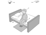
この緊急対応装置1が設置される建物8内には、例えば、 ====に示すような、室内外に監視カメラや各種センサー(人感センサー93のほか光センサー、赤外線センサー、振動・加速度センサー、温度センサー等)が設置されている。また、居住者Uの身体に装着されたウェアラブルセンサー(脈拍センサ、体温計、加速度センサ、GPS等)91、ベッドに設置されて就寝時の体動を検知するベッドセンサ92、室内の二酸化炭素や臭いを検知する匂いセンサー94等が利用されている。これらの各種センサーによる検出データは、緊急対応装置1やサーバーに送信され収集される。また、監視カメラは、静止画、又は動画を撮影する撮影装置であり、一定方向に向けて配置され、建物内外において周囲を継続的に撮影する。また、監視カメラは、回転台が回転することにより、一定範囲の周囲を撮影することができるようになっていてもよいし、例えば全方位カメラなどを利用してもよい。この監視カメラによって撮影された画像データ又は動画データは、無線通信を通じて緊急対応装置1に入力されるようになっている。
管理サーバ2は、本システム提供者が運用するサーバ装置であり、各家庭内に設置される緊急対応装置1や監視カメラ、各種センサーを管理したり、緊急対応装置1や監視カメラ、各種センサーから送信される各種データを蓄積する。さらに、管理サーバ2は、例えば、Webサーバ及びアプリケーションサーバ、データベースサーバなど機能を分配された複数の装置からなるサーバ群で構成されている。
関係機関サーバ4は、警備会社又は警察等の犯罪に関する関係機関に備えられた情報処理装置である。なお、この関係機関としては、例えばコンビニエンスストアやファミリーレストランの他、24時間営業していて店員が常駐しているような施設も含まれる。本実施形態において関係機関サーバ4は、緊急対応装置1又はユーザー端末3からの通報を電話又はデータ通信によって取得するようになっている。
(各装置の構造)
次いで、上述した緊急対応システムを構成する各装置の構造について説明する。====は、本実施形態に係る緊急対応装置1の内部構成を示すブロック図であり、====は、本実施形態に係るユーザー端末3の内部構成を示すブロック図であり、====は、本実施形態に係る管理サーバ2の内部構成を示すブロック図である。なお、説明中で用いられる「モジュール」とは、装置や機器等のハードウェア、或いはその機能を持ったソフトウェア、又はこれらの組み合わせなどによって構成され、所定の動作を達成するための機能単位を示す。
次いで、上述した緊急対応システムを構成する各装置の構造について説明する。====は、本実施形態に係る緊急対応装置1の内部構成を示すブロック図であり、====は、本実施形態に係るユーザー端末3の内部構成を示すブロック図であり、====は、本実施形態に係る管理サーバ2の内部構成を示すブロック図である。なお、説明中で用いられる「モジュール」とは、装置や機器等のハードウェア、或いはその機能を持ったソフトウェア、又はこれらの組み合わせなどによって構成され、所定の動作を達成するための機能単位を示す。
(1)緊急対応装置1の構成
先ず、緊急対応装置1の構成について説明する。本実施形態において、緊急対応装置1は、====に示すように、開閉蓋12aを有するキーボックス12と、開閉蓋12aを施錠または解錠する施錠・解錠駆動部11と、通信機能及び演算機能を有する制御部110と、警報用の各種出力装置を備えている。また、緊急対応装置1には、緊急対応装置1の筐体の外側に設けられ発光、音響出力又は情報表示によって緊急信号により通知された異常を報知する各種報知手段が設けられている。また、緊急対応装置1には、筐体の外側において外方(ここでは、前面側前方)に向けて取り付けられたCCDカメラ13と、緊急対応装置1の外側において外方(ここでは、前面側前方)に向けて取り付けられて、CCDカメラ13により撮影された映像を表示する表示ディスプレイ16とをさらに備える。
先ず、緊急対応装置1の構成について説明する。本実施形態において、緊急対応装置1は、====に示すように、開閉蓋12aを有するキーボックス12と、開閉蓋12aを施錠または解錠する施錠・解錠駆動部11と、通信機能及び演算機能を有する制御部110と、警報用の各種出力装置を備えている。また、緊急対応装置1には、緊急対応装置1の筐体の外側に設けられ発光、音響出力又は情報表示によって緊急信号により通知された異常を報知する各種報知手段が設けられている。また、緊急対応装置1には、筐体の外側において外方(ここでは、前面側前方)に向けて取り付けられたCCDカメラ13と、緊急対応装置1の外側において外方(ここでは、前面側前方)に向けて取り付けられて、CCDカメラ13により撮影された映像を表示する表示ディスプレイ16とをさらに備える。
緊急対応装置1は、緊急対応装置1の筐体の外側に設けられ発光、音響出力又は情報表示によって緊急信号により通知された異常を報知する各種報知手段が設けられている。また、緊急対応装置1には、筐体の外側において外方(ここでは、前面側前方)に向けて取り付けられたCCDカメラ13と、緊急対応装置1の外側において外方(ここでは、前面側前方)に向けて取り付けられて、CCDカメラ13により撮影された映像を表示する表示ディスプレイ16とをさらに備える。
また、本実施形態において開閉蓋12aは、図3に示すように、箱体1の前面に沿って水平に配置された軸12bによって回転可能に軸支され、軸12bを中心に回転することによって開閉するようになっている。回転蓋12aが90°回転することによってキーボックス12が開放され、内部に収納された鍵81を取り出せるようになっている。このキーボックス12内において鍵81は内部の上面から吊り下げられて収納されるようになっている。これにより開閉蓋12aが解錠されて、例えば近隣の住民Nがキーボックス12内部の鍵81を取り出そうとしたときに、近隣住民Nは、開閉蓋12aを90°回転させることにより形成された隙間から内部を覗き込みつつさらにその隙間から手Nhを入れて、上部から吊り下げられた鍵81を取ることとなる。このように敢えて取りづらい構造とすることにより、鍵81を取り出す際、その行為を行った者は屈むなりの不自然な姿勢を取らなければならず、装置1前面に配置されたカメラ13に必ず映り込むこととなる。その結果、例えば、カメラ13の撮影範囲を避けて装置1に近づき、緊急時の混乱に紛れて鍵81を盗むような行為が難しくなり、緊急事態発生時における防犯対策となる。
緊急対応装置1の内部構成については、====に示すように、緊急対応装置1は、無線インターフェース101と、入力インターフェース104と、出力インターフェース102と、制御部110と、記録部103とを備えている。
無線インターフェース101は、無線による双方向通信を行うインターフェースであり、無線LAN等のデータ通信用のプロトコルによる無線通信とを実行する。この場合、データ通信用の無線インターフェースとしては、例えば、無線LAN接続を行うためにIEEE 802.11bに準拠した送受信装置とすることができる。なお、この無線インターフェースは、無線LANアダプタ等により実現することができる。本実施形態において、無線インターフェース101は、中継装置7を介して、CCDカメラ13で撮影した画像やマイク104aで取得した音響を管理サーバ2に送信するようになっている。
無線インターフェース101は、無線による双方向通信を行うインターフェースであり、無線LAN等のデータ通信用のプロトコルによる無線通信とを実行する。この場合、データ通信用の無線インターフェースとしては、例えば、無線LAN接続を行うためにIEEE 802.11bに準拠した送受信装置とすることができる。なお、この無線インターフェースは、無線LANアダプタ等により実現することができる。本実施形態において、無線インターフェース101は、中継装置7を介して、CCDカメラ13で撮影した画像やマイク104aで取得した音響を管理サーバ2に送信するようになっている。
本実施形態において、無線インターフェース101には、接続処理部101aを有している。接続処理部101aは、中継装置7と無線通信を介して、通信接続を確立するためのモジュールであり、接続用プロトコル(自機を特定するための識別子を含む)を接続対象となる中継装置7に送信し、認証を行う。なお、接続処理部101aは、中継装置7との間で無線LAN接続を行う場合には、データの送受信を行うためのリンクを張るために、無線信号を監視し、中継装置7を識別するESSIDを検出するようにしてもよい。無線インターフェース101は、中継装置7が建物8内の監視カメラ・検知装置9又はユーザー端末3と接続処理を行い、接続用プロトコルを取得した場合にはその監視カメラ・検知装置9又はユーザー端末3とも通信が可能となる。
入力インターフェース104は、画像及び音響を取得するデバイスであり、入力インターフェースには、音声などの音響を取得するマイク104aや、静止画、又は動画を撮影する撮影装置であるCCDカメラ13が含まれている。なお、このCCDカメラ13は、緊急対応装置1の前面に設置され、表示ディスプレイ16と並んで配置された撮影装置であり、駆動手段によって撮影方向が変更可能となっている。なお、本実施形態において、入力インターフェース104は、建物8内に設置された監視カメラ・検知装置9によって撮影された画像データや検知された各種検出データも宅内の通信ネットワークを介して取得可能となっている。
出力インターフェース102は、光や映像、音響を出力するデバイスである。特に、この出力インターフェース102には、緊急対応装置1の前面に配置された表示ディスプレイ16などの表示部102bと、音楽、効果音、警報及び音声などの音響を出力するスピーカー102aが含まれている。
記録部103は、OS(Operating System)や各種のアプリケーション用のプログラム、緊急対応装置1を識別する装置ID、その他のデータ等などを記憶する記憶装置である。記録部103には、管理サーバ2から取得した犯罪者の情報(犯罪者の名前、顔や体型などの画像データ等)が蓄積される。犯罪者の情報は、警察などの関係機関からの情報提供や、自治体などによる地域ごとの犯罪情報、公開された情報より取得可能である。さらに、居住者が特定の人物をストーカー登録した場合には、その人物に対する情報(名前、性別、顔画像、音声、名前、電話番号、メールアドレスの他、ユーザー端末に対して送られたメール履歴情報や着信履歴情報等)が記録される。このストーカー情報は、ユーザー操作によって、関係機関サーバ4や管理サーバ2に通報可能である。
制御部110は、一般のOSやブラウザソフトなどのアプリケーションを実行するモジュールであり、通常はCPU等により実現される。この制御部110によって、音声対話機能、物体認識機能の他、例えば人物の表情と声のトーンを分析して人の感情を推定する感情認識機能などが実現される。さらに、本実施形態では、この制御部110に緊急対応機能に係るモジュール群として、画像認識部111と、音響解析部112と、照合部113と、報知部114と、駆動制御部115とを備えている。駆動制御部115は、移動手段の駆動を制御するモジュールであり、各種センサー(図示せず)からの検出信号に基づいて、移動手段を制御して、緊急対応装置1を前進、後退及び旋回させる。
画像認識部111は、CCDカメラ13から取得された画像に写った人物を特定するモジュールである。この画像認識部111は、取得した画像における顔の輪郭部分を、顔認識技術を用いて解析してその人物の顔を認識する。ここで、顔認識技術とは、顔の輪郭部分を特徴点として抽出する技術であって、主成分分析を使った固有顔、線形判別分析、弾性バンチグラフマッチング、隠れマルコフモデル、ニューロン動機づけによるダイナミックリンク照合などが種々の技法を用いることができる。なお、画像認識部111は、例えば、画像中から体型など身体的特徴を含む身体情報を取得し、顔以外の特徴部分を認識してもよい。
なお、画像認識部111には、知人や居住者、外部人物を識別する機能を備えており、記憶部103に蓄積された知人情報、居住者情報、外部人物情報等のデータを照合することにより、人物の特定を行うようになっている。この知人情報としては、緊急対応装置1を識別する装置IDに、居住者や知り合いなどの正当な来訪者に関する情報が関連づけて蓄積される。ここで、知人情報には、その人物の個人情報(名前やあだ名などの呼び名、性別、年齢等)、各自が所持するユーザー端末に関する情報(電話番号、メールアドレス、接続用プロトコル等)、人物特徴データ(顔データ(目、鼻、及び唇の位置関係及び輪郭情報等を含む)、体格情報、音声データ、足音などの行動音等が記録される。
居住者情報については、行動パターン情報として、外出している時間帯情報、在宅している時間帯情報、宅内における居住者の位置情報及び動線情報、玄関の施錠及び解錠を行う動作など居住者の行動パターン、各カメラにおける出現頻度等が記録される。一方、外部の人間に関する行動パターン情報として、来訪回数などの出現頻度、来訪時間帯情報、緊急対応装置1の入力インターフェース104によって収集した居住者との対話内容や音声認識情報等が記録される。また、外部人物情報には、検出したカメラ・センサーの検出位置情報と関連づけて記録されている。この検出位置情報とは、人物を特定した場所や時刻であって、台所、居間、各居住者の部屋、玄関などの位置情報・時間情報が含まれる。また、例えば、監視カメラ・検知装置9から画像や各種センサーによる検出結果を取得した場合には、その監視カメラ・検知装置9やセンサーが設置された場所(建物内、ベランダ、玄関等)の位置情報が記録される。これらの居住者・外部人物情報は、緊急対応装置を設置している居住者、居住者の知り合い、及び近隣者などから継続的に取得し、制御部110の制御によって特定された人物に記録されることで詳細な情報が順次蓄積されていくものとする。
音響解析部112は、マイク104aから取得された音響に係る人物を特定するモジュールである。本実施形態において、音響解析部112は、ユーザーが発する音声、又はユーザーの動作によって発生する種々の音(足音など)などを取得する。音声を取得した場合には、人の声の認識を行う話者認識機能によって特徴部分を抽出する。また、音響解析部112は、音声以外の音響(例えば、足音など)の特徴的な音を解析する。なお、取得される画像及び音響の特徴は、緊急対応装置を設置している居住者、知り合い、及び近隣者とのやり取りから継続的に取得し、以下の照合部113の照合結果を記録部103に記録することでモデル化されていくものとする。
照合部113は、入力インターフェース104等によって取得された映像又は音声などに基づいて知人情報を照合するモジュールである。この照合部113で知人情報を照合することで、CCDカメラ13から取得された画像に写った人物、又はマイク104aから取得された音響に係る人物を特定することができ、照合結果により、来訪者が、通報の必要ない正当な来訪者であるのか、それとも、泥棒などの不正侵入者である可能性があるのかを判定することができる。
報知部114は、照合部113による照合結果に基づいて、現況情報を報知するモジュールである。この報知部114による現況情報の報知には、緊急対応装置1が備えるスピーカー102aや表示部102bから音や画像を出力するものや、通信ネットワーク5を通じて、予め設定された居住者のユーザー端末3、又は関係機関サーバ4に通報するものが含まれる。
具体的に、報知部114は、建物8内で異常が検知された場合、緊急対応装置1に備えられた警告灯14や表示ディスプレイ16、スピーカー15を用いて、建物8近隣に向けて光や警告音を出力する。また、報知部114は、建物8内で異常が検出されたり、不審者が検出されたりした場合、CCDカメラ13で撮影した画像を装置IDとともに管理サーバ2に送出する。さらに、報知部114は、発生した異常に関する情報や、不審者が出現したことを示す現況情報を登録されたユーザー端末3に通知する。また、上記照合部113の照合処理において来訪者が不正侵入者であると判断した場合、報知部114は、監視カメラ・検知装置9等を制御してその人物の画像を撮影し、その画像データを管理サーバ2に送信する。
(2)ユーザー端末3の構成
次いで、ユーザー端末3の構成について説明する。====に示すように、ユーザー端末3は、無線インターフェース31と、入力インターフェース32と、出力インターフェース33と、アプリケーション実行部34と、メモリ35とを備えている。
次いで、ユーザー端末3の構成について説明する。====に示すように、ユーザー端末3は、無線インターフェース31と、入力インターフェース32と、出力インターフェース33と、アプリケーション実行部34と、メモリ35とを備えている。
無線インターフェース31は、通話を行うための移動通信用のプロトコルによる無線通信と、例えば無線LAN等のデータ通信用の接続プロトコルによる無線による双方向通信を行うことを実行するインターフェースである。この場合、データ通信用の無線インターフェースとしては、例えば、無線LAN接続を行うためにIEEE 802.11bに準拠した送受信装置とすることができる。なお、この無線インターフェースは、無線LANアダプタ等により実現することができる。
本実施形態において、無線インターフェース31には、接続処理部31aを有している。接続処理部31aは、中継装置7又は緊急対応装置1と無線通信を介して、通信接続を確立するためのモジュールであり、無線を通じた接続用プロトコル(自機を特定するための識別子を含む)を接続対象となる中継装置7又は緊急対応装置1に送信し、認証を行う。なお、接続処理部31aは、中継装置7又は緊急対応装置1との間で無線LAN接続を行う場合には、データの送受信を行うためのリンクを張るために、無線信号を監視し、中継装置7又は緊急対応装置1を識別するESSIDを検出するようにしてもよい。
入力インターフェース32は、操作ボタンやタッチパネルなどユーザー操作を入力するデバイスである。また、出力インターフェース33は、ディスプレイやスピーカーなど、映像や音響を出力するデバイスである。特に、この出力インターフェース33には、液晶ディスプレイなどの表示部33aが含まれている。
メモリ35は、OS(Operating System)や各種のアプリケーション用のプログラム、その他のデータ等などを記憶する記憶装置であり、このメモリ35内には、ユーザーを識別するユーザーIDの他、アプリケーション実行部34で処理される各種プログラム、及びデータ、接続プロトコル等が蓄積される。
アプリケーション実行部34は、一般のOSやブラウザソフトなどのアプリケーションを実行するモジュールであり、通常はCPU等により実現される。このアプリケーション実行部34では、通常の通話機能や、ブラウザ機能、及び電子メール機能を有するととともに、本発明に係るプログラムが実行されることで、報知情報取得部34aと、通報処理部34bとが仮想的に構築される。
報知情報取得部34aは、緊急対応装置1から報知された現況情報を取得するとともに、管理サーバ2にアクセスして、管理サーバ2内に蓄積された不正侵入者の顔データ等を取得するモジュールである。報知情報取得部34aは、緊急対応装置1から現況情報を取得すると不正侵入者がいる旨を表示部33a上に表示させる。また、報知情報取得部34aは、利用者の操作に基づいて管理サーバ2にアクセスすると、該当する画像データ又は音響データを取得し、表示部3a等に表示させる。なお、不正侵入者がいる旨の通知は、専用のアプリケーションによって通知してもよく、電子メール等で通知してもよい。また、管理サーバ2にアクセスする場合は、一般的なブラウザソフトを用いてアクセスしてもよく、専用アプリケーションを用いてアクセス可能としてもよい。
通報処理部34bは、現況情報を参照した利用者のユーザー操作に基づいて、関係機関に通報を行うモジュールである。この通報処理部34bで行われる通報処理としては、例えば、電話による通報の他、専用アプリケーション又は電子メールを用いた通報など種々の方式を用いることができる。
(3)管理サーバ2の構成
次いで、管理サーバ2の構成について説明する。管理サーバ2は、単一のサーバ装置の他、Webサーバやデータベースサーバなど複数のサーバ群から構成することができ、本実施形態では、====に示すように、通信インターフェース21と、制御部22と、記憶部23とを備えている。
次いで、管理サーバ2の構成について説明する。管理サーバ2は、単一のサーバ装置の他、Webサーバやデータベースサーバなど複数のサーバ群から構成することができ、本実施形態では、====に示すように、通信インターフェース21と、制御部22と、記憶部23とを備えている。
記憶部23は、本システムに関する各種の情報を蓄積するデータベース群であり、ここでは、装置情報蓄積部23aと、ユーザー情報蓄積部23bと、周辺情報蓄積部23cとを備えている。なお、各データベースは、単体のデータベースとして構成してもよいし、複数のデータベース間でリレーションシップを設定するようにしてもよい。
装置情報蓄積部23aは、緊急対応装置1や各種センサーに関する情報を蓄積するデータベースであり、緊急対応装置1を識別する装置IDに、緊急対応装置1に関する情報(製造番号、設定、OS情報等)などが記録されている。ユーザー情報蓄積部23bは、緊急対応装置1を所持する居住者に関する情報を蓄積するデータベースであり、本実施形態では、緊急対応装置1を識別する装置IDに、緊急対応装置1から送信された現況情報(画像データ、音声データなど)を蓄積している。なお、このユーザー情報蓄積部23bには、利用者からの登録があった場合には、居住者及び知り合い等の人物に関する情報が関連づけて記録される。なお、この情報とは、緊急対応装置1の記録部103に蓄積される知人情報と同様である。周辺情報蓄積部23cは、関係機関サーバ4から取得した、建物8周辺に関する情報(救急搬送の発生率や事故・事件の発生情報、不審者情報等)を蓄積するデータベースである。この周辺情報蓄積部23cの情報は、通信ネットワーク5を通じて、緊急対応装置1に配信される。
制御部22は、CPUやDSP(Digital Signal Processor)等のプロセッサ、メモリ、及びその他の電子回路等のハードウェア、或いはその機能を持ったプログラム等のソフトウェア、又はこれらの組み合わせなどによって構成された演算モジュールであり、プログラムを適宜読み込んで実行することにより種々の機能モジュールを仮想的に構築し、構築された各機能モジュールによって、各部の動作制御、ユーザー操作に対する種々の処理を行っている。そして、本実施形態において、制御部22には、認証部22aと、現況情報管理部22bと、情報配信部22cとを備えている。認証部22aは、アクセス者の正当性を検証するコンピューター或いはその機能を持ったソフトウェアであり、緊急対応装置1及びユーザー端末3からのアクセスに対して、装置IDやユーザーIDに基づいて認証処理を実行する。
本実施形態では、緊急対応装置1が不正侵入者の可能性有りと判断した場合には、通信ネットワーク5を通じて、この管理サーバ2と同期処理が行われる。この際、認証部22aは、緊急対応装置1から装置IDを取得し、装置情報蓄積部23aを照合することによって、アクセス権利があるか否かなどを確認する。また、ユーザー端末3がアクセスしてきた場合には、認証部22aは、ユーザー端末3からユーザーIDを取得し、ユーザー情報蓄積部23bを照合することによって、アクセス権利があるか否かなどを確認する。
現況情報管理部22bは、認証部22aによって承認された緊急対応装置1から現況情報を取得し、装置IDに基づいてユーザー情報蓄積部23bに現況情報を記録するモジュールである。情報配信部22cは、各種のデータを緊急対応装置1又はユーザー端末3に配信するモジュールである。情報配信部22cは、周辺情報蓄積部23cを緊急対応装置1に配信したり、アクセスがあったユーザー端末3に対して、自宅で撮影された画像データや音声データを含む現況情報を配信する。なお、情報配信部22cは、この現況情報を警備会社や警察などに送信可能となっている。
(変更例)
なお、以上説明した実施形態の説明は、本発明の一例である。このため、本発明は上述した実施形態に限定されることなく、本発明に係る技術的思想を逸脱しない範囲であれば、設計等に応じて種々の変更が可能である。例えば、上述した実施形態ではキーボックス12を建物8外に後付けする構成としたが、図9及び図10に示すように、屋外の塀や家屋の外壁などの壁体82の壁厚面内にキーボックス12を埋め込む構成としてもよい。
なお、以上説明した実施形態の説明は、本発明の一例である。このため、本発明は上述した実施形態に限定されることなく、本発明に係る技術的思想を逸脱しない範囲であれば、設計等に応じて種々の変更が可能である。例えば、上述した実施形態ではキーボックス12を建物8外に後付けする構成としたが、図9及び図10に示すように、屋外の塀や家屋の外壁などの壁体82の壁厚面内にキーボックス12を埋め込む構成としてもよい。
詳述すると、壁体82内に収納空間を形成しキーボックス12を埋め込むように配置する。ここでのキーボックス12は、壁体82の前面(表側面)に内部の収納空間に通じる開口12cを有し、この開口12cを通じて前面側から内部にアクセスして内部の鍵81を取り出せるようになっている。
また、開口12cには、その前面を塞ぐ開閉蓋12bが取付けられる。この開閉蓋12bは、開口12cを覆うように壁体82の側壁面に平行となるように配置される板部材であり、その裏面に4本のロッド部材121が突設されている。ロッド部材121は、開閉蓋12bの裏面側においてその四隅に配置され、その端部周面にはボトルネック状に括れられた溝部121aがそれぞれ形成されている。そして、これらのロッド部材121は、壁体82を貫通された貫通孔82aにそれぞれ挿通されて壁体82を貫通され、その端部の溝部121aが壁体82の裏面側に突出され、施錠・解錠駆動部を構成する固定手段11aによって把持されて、貫通孔82aから抜けないように固定される。
固定手段11aは、施錠駆動手段として、壁体82を貫通されたロッド部材121端部を壁体82の裏面側で固定する機構であり、制御部22によって制御される電流を機械的運動に変換する仕組みを備えている。具体的には、固定手段11aの内部に制御部22から制御信号により駆動するソレノイドコイルを備えており、このソレノイドコイルに電流が流れると可動ピン11bが磁化され、磁力による吸引力及びバネ等の弾性部材の弾力により可動ピン11bが上下に駆動し、ロッド部材121を固定又は開放する。この固定手段11aによりロッド部材121が固定されると開閉蓋12bは壁体82の壁面に固定されてキーボックス12は閉止され(図10(a))、ロッド部材121の固定が開放されることにより解錠されて開閉蓋12bが取り外し可能となる(図10(b))。
(緊急対応方法)
上述した緊急対応システムにより、本実施形態に係る緊急対応方法を実施することができる。====は、本実施形態に係る緊急対応方法を示すフローチャート図である。なお、ここでは、既に居住者及び知り合いに関する知人情報が記録部103内に蓄積されているものとする。
(緊急対応方法)
上述した緊急対応システムにより、本実施形態に係る緊急対応方法を実施することができる。====は、本実施形態に係る緊急対応方法を示すフローチャート図である。なお、ここでは、既に居住者及び知り合いに関する知人情報が記録部103内に蓄積されているものとする。
先ず、緊急対応装置1の制御部110では、常時、入力インターフェース104等からの検知信号を取得し、異常が発生したか否かを判断する(S101)。この検知信号とは、建物8内のカメラや各種センサーが検知した際に取得される信号である。制御部110では、いずれかの検知信号の異常が検出されるまで、この監視処理を繰り返し行っている(S101における“N”)。
この異常検出は、建物8内に関する情報が取得される画像や居住者の位置などの解析処理により実現される。例えば、CCDカメラ13や監視カメラ・検知装置9から画像を取得した場合には、画像認識部111において、その画像が解析され、人物の顔や体型による特徴部分が抽出される。一方、マイク104aから音響を取得した場合には、音響解析部112において、その音響が解析され、人物の音声や足音,異常音などの特徴部分が抽出される。そして、解析された特徴部分は、照合部113に入力される。照合部113は、取得された映像又は音声を含む来訪者に関する情報について、記録部103内の知人情報を照合する。また、居住者の位置が一定時間以上移動しなかったり、普段の動線から外れた行動を取っていたりなどのデータ解析により異常を検出する。
そして、制御部110においていずれかの検知信号の異常が取得されると(S101における“Y”)、その検知された種類に応じて各部を制御して、発生した異常に関する情報を取得して、緊急通知及び近隣へ報知を実行する(S102)。本実施形態では、近隣への報知としては、緊急対応装置1の外側に設けられた警告灯14やスピーカ15、表示ディスプレイ16が発光、音響出力又は情報表示によって異常の発生を近隣や周囲住民に報知するとともに、保護者等の関係者が使用する端末3に報知メールなどのアラートを送信する。これにより、迅速に異常の発生を周知させることができ、迅速な対応を促すことができる。なお、上記「異常に関する情報」とは、監視カメラ・検知装置9やCCDカメラ13で撮影される画像データや検出データ、マイク104aから取得される音響データ、家に設置される中継装置7から取得される接続プロトコル等が含まれる。
これと合わせて、異常の発生を通知する緊急信号の受信に応じて、キーボックス12の開閉蓋12aを解錠して開放可能な状態とする(S103)。これにより、救急のために駆けつけた者は、キーボックス12内の鍵81を取り出すことができることから、進入口80から建物8内に速やかに進入して救急活動を行うことができ、高齢者の独居住宅などで異常が発生したときなど緊急を要する異常事態に迅速に対応できる。
また、本実施形態では、緊急対応装置1のキーボックス12の外側前面に、外方に向けて取り付けられたカメラ13が撮影した映像を、キーボックス12の外側前面にカメラ13と並んで配置された表示ディスプレイ16に表示させる(S104)。これにより、緊急事態が発生しているときに、緊急対応装置1の前方に位置した人物を撮影してそのまま表示ディスプレイ16に表示させることができ、気づかないふりや見て見ぬふりをできなくして迅速な救急活動を強く促すことができるという、心理的効果も期待できる。
なお、ステップS102において報知部114は、照合部113による照合結果に基づいて、現況情報を報知する。具体的に、報知部114は、CCDカメラ13等で撮影した画像やマイク104aで取得した音響データ等を装置IDとともに管理サーバ2に送信する。また、報知部114は、異常が発生したことを示す現況情報を登録されたユーザー端末3に通知する。この際、報知部114は、照合部113において接続用プロトコルの照合を行った場合、その照合結果又は接続用プロトコルの成否についても、現況情報に含めて管理サーバ2及びユーザー端末3に報知する。
管理サーバ2では、認証処理の後、緊急対応装置1から送信された画像データ等をユーザー情報蓄積部23bに記録する。また、ユーザー端末3の報知情報取得部34aでは、緊急対応装置1から異常が発生した旨の通知を受信すると表示部33a上に通知情報を表示させる。その後、ユーザー操作に基づいて、管理サーバ2にアクセスする。管理サーバ2では、認証部22aによる認証の後、ユーザー情報蓄積部23bに蓄積された画像データをユーザー端末3に配信する。ユーザー端末3の報知情報取得部34aでは、この画像データを受信して、表示部33a上に画像データを表示する。
その後、通報処理部34bは、ユーザー操作によって通報操作を受け付けると電話機能や電子メール機能が起動され、関係機関に対して通報を行う。この際、異常が発生した現場や不審者等が写った画像データは、管理サーバ2側から送信してもよいし、ユーザー端末3から送信してもよい。その後、緊急対応装置1の制御部110では、不正侵入者有りの判断結果と、画像データ等とを記録部103内に記録する(S105)。
緊急対応装置1では、監視処理が終了となるまで(S106における“Y”)、上記ステップS101からステップS105の処理を繰り返し行う(S106における“N”)。ここで、監視処理が終了となるのは、例えば、居住者が帰宅して監視処理機能をオフにした場合などである。
(作用・効果)
このような本実施形態によれば、緊急対応装置1を建物8の外部に設置し、建物8内への進入口80の施錠を解除するための鍵81をキーボックス12内に収納しておく。平常時はキーボックス12は施錠されているため、中に収納された鍵81が安全に保管された状態となる。そして、建物8内において居住者が倒れていたり、一定時間以上動かなかったりなどの異常が検知された場合には、その旨を通知する緊急信号の受信に応じて、キーボックス12の開閉蓋12aを解錠して開放可能な状態とする。これにより、救急のために駆けつけた者は、キーボックス12内の鍵81を取り出すことができることから、進入口80から建物8内に速やかに進入して救急活動を行うことができ、例えば高齢者の独居住宅などで異常が発生したときなど緊急を要する異常事態に迅速に対応できる。
このような本実施形態によれば、緊急対応装置1を建物8の外部に設置し、建物8内への進入口80の施錠を解除するための鍵81をキーボックス12内に収納しておく。平常時はキーボックス12は施錠されているため、中に収納された鍵81が安全に保管された状態となる。そして、建物8内において居住者が倒れていたり、一定時間以上動かなかったりなどの異常が検知された場合には、その旨を通知する緊急信号の受信に応じて、キーボックス12の開閉蓋12aを解錠して開放可能な状態とする。これにより、救急のために駆けつけた者は、キーボックス12内の鍵81を取り出すことができることから、進入口80から建物8内に速やかに進入して救急活動を行うことができ、例えば高齢者の独居住宅などで異常が発生したときなど緊急を要する異常事態に迅速に対応できる。
また、本実施形態では、異常が検知された場合に緊急対応装置1の外側に設けられた警告灯14やスピーカ15、表示ディスプレイ16が発光、音響出力又は情報表示によって異常の発生を近隣や周囲住民に報知するとともに、保護者等の関係者が使用する端末3に報知メールなどのアラートを送信するため、迅速に異常の発生を周知させることができ、迅速な対応を促すことができる。さらに、本実施形態では、緊急対応装置1のキーボックス12の外側前面に、外方に向けて取り付けられたカメラ13が撮影した映像を、キーボックス12の外側前面にカメラ13と並んで配置された表示ディスプレイ16に表示させる。これにより、緊急事態が発生しているときに、緊急対応装置1の前方に位置した人物を撮影してそのまま表示ディスプレイ16に表示させることができ、気づかないふりや見て見ぬふりをできなくして迅速な救急活動を強く促すことができるという、心理的効果も期待できる。
なお、本発明は、上記した各実施の形態そのままに限定されるものではなく、実施段階ではその要旨を逸脱しない範囲で構成要素を変形して具体化できる。また、上記実施の形態に開示されている複数の構成要素の適宜な組み合せにより、種々の発明を形成できる。例えば、実施の形態に示される全構成要素から幾つかの構成要素を削除してもよい。
1…緊急対応装置
2…管理サーバ
3…ユーザー端末
3a…表示部
4…関係機関サーバ
5…通信ネットワーク
6…無線基地局
7…中継装置
8…建物
9…監視カメラ・検知装置
11…施錠・解錠駆動部
12…キーボックス
12a,12b…開閉蓋
13…CCDカメラ
14…警告灯
15…スピーカー
16…表示ディスプレイ
21…通信インターフェース
22…制御部
22a…認証部
22b…現況情報管理部
22c…情報配信部
23…記憶部
23a…装置情報蓄積部
23b…ユーザー情報蓄積部
23c…周辺情報蓄積部
31…無線インターフェース
31a…接続処理部
32…入力インターフェース
33…出力インターフェース
33a…表示部
34…アプリケーション実行部
34a…報知情報取得部
34b…通報処理部
35…メモリ
80…進入口
81…鍵
82…壁体
101…無線インターフェース
101a…接続処理部
102…出力インターフェース
102a…スピーカー
102b…表示部
103…記録部
104…入力インターフェース
104a…マイク
110…制御部
111…画像認識部
112…音響解析部
113…照合部
114…報知部
115…駆動制御部
121…ロッド部材
Claims (7)
- 開閉手段を有する収納手段と、
前記開閉手段を施錠または解錠する施錠駆動手段と、
異常が検知された旨を通知する緊急信号を受信する受信手段と、
前記緊急信号の受信に応じて前記施錠駆動手段を駆動させて前記開閉手段を解錠する制御手段と
を備えることを特徴とする緊急対応システム。 - 前記収納手段の外側に設けられ発光、音響出力又は情報表示によって、前記緊急信号により通知された異常を報知する報知手段をさらに備えることを特徴とする請求項1に記載の緊急対応システム。
- 前記収納手段の外側において外方に向けて取り付けられた撮影手段と、
前記収納手段の外側において外方に向けて取り付けられ、前記撮影手段により撮影された映像を表示するディスプレイ手段と
をさらに備えることを特徴とする請求項1または2に記載の緊急対応システム。 - 建物内における異常を検知する検知手段と、
前記検知手段が検知した異常を通知する前記緊急信号を送信する送信手段と
をさらに備え
前記収納手段は前記建物の外部に設置される
ことを特徴とする請求項1に記載の緊急対応システム。 - 前記収納手段は、壁体内に形成されるとともに、前記壁体の側面に内部の収納空間に通じる開口を有し、
前記開閉手段は、前記開口を覆うように前記側面に平行に配置された板部材であり、
前記施錠駆動手段は、前記板部材の裏面に突設され前記壁体を貫通されたロッド部材の端部を前記壁体の裏面側に固定する固定手段を含み、
前記制御手段は、前記固定手段による固定を開放することで前記解錠を行う
ことを特徴とする請求項1に記載の緊急対応システム。 - 開閉手段を有する収納手段を建物の外部に設置し、前記建物への進入口の施錠を解除するための鍵を前記収納手段内に収納し、前記鍵を収納した状態で前記施錠駆動手段が前記開閉手段を施錠するステップと、
検知手段が前記建物内における異常を検知するとともに、前記検知手段が検知した異常を通知する前記緊急信号を送信手段が送信するステップと、
制御手段が、前記緊急信号の受信に応じて前記施錠駆動手段を駆動させて前記開閉手段を解錠するステップと
を含むことを特徴とする緊急対応方法。 - 前記収納手段の外側に設けられた報知手段が、発光、音響出力又は情報表示によって、前記緊急信号により通知された異常を報知するとともに、前記収納手段の外側において外方に向けて取り付けられた撮影手段が撮影した映像を、前記収納手段の外側において外方に向けて取り付けられたディスプレイ手段が表示するステップをさらに含むことを特徴とする請求項6に記載の緊急対応方法。
Priority Applications (1)
| Application Number | Priority Date | Filing Date | Title |
|---|---|---|---|
| JP2022508418A JPWO2021187538A1 (ja) | 2020-03-17 | 2021-03-17 |
Applications Claiming Priority (2)
| Application Number | Priority Date | Filing Date | Title |
|---|---|---|---|
| JP2020-046032 | 2020-03-17 | ||
| JP2020046032 | 2020-03-17 |
Publications (1)
| Publication Number | Publication Date |
|---|---|
| WO2021187538A1 true WO2021187538A1 (ja) | 2021-09-23 |
Family
ID=77771685
Family Applications (1)
| Application Number | Title | Priority Date | Filing Date |
|---|---|---|---|
| PCT/JP2021/010892 WO2021187538A1 (ja) | 2020-03-17 | 2021-03-17 | 緊急システム |
Country Status (2)
| Country | Link |
|---|---|
| JP (1) | JPWO2021187538A1 (ja) |
| WO (1) | WO2021187538A1 (ja) |
Citations (3)
| Publication number | Priority date | Publication date | Assignee | Title |
|---|---|---|---|---|
| JP2001082006A (ja) * | 1999-09-17 | 2001-03-27 | Nippon Signal Co Ltd:The | 鍵保管装置 |
| JP2006350947A (ja) * | 2005-06-20 | 2006-12-28 | Unitex:Kk | 宅配ボックス |
| JP2014098955A (ja) * | 2012-11-13 | 2014-05-29 | Lsi Japan Kk | 自動受付装置および受付システム |
-
2021
- 2021-03-17 WO PCT/JP2021/010892 patent/WO2021187538A1/ja active Application Filing
- 2021-03-17 JP JP2022508418A patent/JPWO2021187538A1/ja active Pending
Patent Citations (3)
| Publication number | Priority date | Publication date | Assignee | Title |
|---|---|---|---|---|
| JP2001082006A (ja) * | 1999-09-17 | 2001-03-27 | Nippon Signal Co Ltd:The | 鍵保管装置 |
| JP2006350947A (ja) * | 2005-06-20 | 2006-12-28 | Unitex:Kk | 宅配ボックス |
| JP2014098955A (ja) * | 2012-11-13 | 2014-05-29 | Lsi Japan Kk | 自動受付装置および受付システム |
Also Published As
| Publication number | Publication date |
|---|---|
| JPWO2021187538A1 (ja) | 2021-09-23 |
Similar Documents
| Publication | Publication Date | Title |
|---|---|---|
| AU2023270262B2 (en) | Doorbell call center | |
| AU2018275266B2 (en) | Control access utilizing video analytics | |
| CN107408316A (zh) | 门和住宅安全系统以及方法 | |
| JP6182170B2 (ja) | セキュリティシステム | |
| JP7265995B2 (ja) | 監視及びコンシェルジェサービスのためのスケーラブルなシステム及び方法 | |
| US20140125754A1 (en) | Web portal for managing premise security | |
| JP2004013871A (ja) | 防犯システム | |
| WO2021187538A1 (ja) | 緊急システム | |
| JP2003331371A (ja) | セルフセキュリティシステム、及びそのセキュリティ監視方法、並びにセルフセキュリティサービス提供プログラム、記録媒体 | |
| EP2943873A1 (en) | Web portal for managing premise security | |
| JP2022028739A (ja) | 開閉装置、セキュリティサーバおよびセキュリティシステム | |
| JP2006146432A (ja) | 警備システム | |
| Suresh et al. | Comprehensive Home Security for Elderly People using IoT and Artificial Intelligence | |
| WO2022113322A1 (ja) | セキュリティシステムおよびセキュリティ装置 | |
| Valarmathi et al. | Design and Implementation of Secured Contactless Doorbell using IOT | |
| JP2018162608A (ja) | 金品管理システム、金庫、金品管理方法 | |
| Advirkar et al. | Smart Surveillance System | |
| JP2008102692A (ja) | 集合住宅インターホン防犯設定システム、及びインターホン防犯設定システム | |
| JP2003199088A (ja) | 監視システム |
Legal Events
| Date | Code | Title | Description |
|---|---|---|---|
| 121 | Ep: the epo has been informed by wipo that ep was designated in this application |
Ref document number: 21771915 Country of ref document: EP Kind code of ref document: A1 |
|
| ENP | Entry into the national phase |
Ref document number: 2022508418 Country of ref document: JP Kind code of ref document: A |
|
| NENP | Non-entry into the national phase |
Ref country code: DE |
|
| 122 | Ep: pct application non-entry in european phase |
Ref document number: 21771915 Country of ref document: EP Kind code of ref document: A1 |