WO2021187410A1 - 流体回路及び血圧測定装置 - Google Patents
流体回路及び血圧測定装置 Download PDFInfo
- Publication number
- WO2021187410A1 WO2021187410A1 PCT/JP2021/010339 JP2021010339W WO2021187410A1 WO 2021187410 A1 WO2021187410 A1 WO 2021187410A1 JP 2021010339 W JP2021010339 W JP 2021010339W WO 2021187410 A1 WO2021187410 A1 WO 2021187410A1
- Authority
- WO
- WIPO (PCT)
- Prior art keywords
- fluid
- cuff
- blood pressure
- fluid resistance
- valve
- Prior art date
- Legal status (The legal status is an assumption and is not a legal conclusion. Google has not performed a legal analysis and makes no representation as to the accuracy of the status listed.)
- Ceased
Links
Images








Classifications
-
- A—HUMAN NECESSITIES
- A61—MEDICAL OR VETERINARY SCIENCE; HYGIENE
- A61B—DIAGNOSIS; SURGERY; IDENTIFICATION
- A61B5/00—Measuring for diagnostic purposes; Identification of persons
- A61B5/02—Detecting, measuring or recording for evaluating the cardiovascular system, e.g. pulse, heart rate, blood pressure or blood flow
- A61B5/021—Measuring pressure in heart or blood vessels
- A61B5/022—Measuring pressure in heart or blood vessels by applying pressure to close blood vessels, e.g. against the skin; Ophthalmodynamometers
- A61B5/0225—Measuring pressure in heart or blood vessels by applying pressure to close blood vessels, e.g. against the skin; Ophthalmodynamometers the pressure being controlled by electric signals, e.g. derived from Korotkoff sounds
-
- A—HUMAN NECESSITIES
- A61—MEDICAL OR VETERINARY SCIENCE; HYGIENE
- A61B—DIAGNOSIS; SURGERY; IDENTIFICATION
- A61B5/00—Measuring for diagnostic purposes; Identification of persons
- A61B5/02—Detecting, measuring or recording for evaluating the cardiovascular system, e.g. pulse, heart rate, blood pressure or blood flow
- A61B5/021—Measuring pressure in heart or blood vessels
- A61B5/022—Measuring pressure in heart or blood vessels by applying pressure to close blood vessels, e.g. against the skin; Ophthalmodynamometers
- A61B5/02233—Occluders specially adapted therefor
-
- A—HUMAN NECESSITIES
- A61—MEDICAL OR VETERINARY SCIENCE; HYGIENE
- A61B—DIAGNOSIS; SURGERY; IDENTIFICATION
- A61B5/00—Measuring for diagnostic purposes; Identification of persons
- A61B5/02—Detecting, measuring or recording for evaluating the cardiovascular system, e.g. pulse, heart rate, blood pressure or blood flow
- A61B5/021—Measuring pressure in heart or blood vessels
- A61B5/022—Measuring pressure in heart or blood vessels by applying pressure to close blood vessels, e.g. against the skin; Ophthalmodynamometers
- A61B5/0235—Valves specially adapted therefor
-
- A—HUMAN NECESSITIES
- A61—MEDICAL OR VETERINARY SCIENCE; HYGIENE
- A61B—DIAGNOSIS; SURGERY; IDENTIFICATION
- A61B5/00—Measuring for diagnostic purposes; Identification of persons
- A61B5/68—Arrangements of detecting, measuring or recording means, e.g. sensors, in relation to patient
- A61B5/6801—Arrangements of detecting, measuring or recording means, e.g. sensors, in relation to patient specially adapted to be attached to or worn on the body surface
- A61B5/6802—Sensor mounted on worn items
- A61B5/681—Wristwatch-type devices
-
- A—HUMAN NECESSITIES
- A61—MEDICAL OR VETERINARY SCIENCE; HYGIENE
- A61B—DIAGNOSIS; SURGERY; IDENTIFICATION
- A61B2562/00—Details of sensors; Constructional details of sensor housings or probes; Accessories for sensors
- A61B2562/02—Details of sensors specially adapted for in-vivo measurements
- A61B2562/0247—Pressure sensors
Definitions
- the present invention relates to a fluid circuit and a blood pressure measuring device used for blood pressure measurement.
- blood pressure measuring devices used for measuring blood pressure have been used as a means for checking the health condition not only in medical facilities but also at home.
- the blood pressure measuring device for example, expands and contracts a cuff wrapped around the upper arm or wrist of a living body, detects the pressure of the cuff with a pressure sensor, and detects the vibration of the arterial wall to measure the blood pressure.
- Such a blood pressure measuring device is known to have a technique including a sensing cuff for measuring blood pressure and a plurality of cuffs including a pressing cuff for pressing the sensing cuff toward a living body.
- the blood pressure measuring device has a pump, and the cuff is inflated by supplying a fluid such as air to the cuff by the pump.
- Japanese Patent Application Laid-Open No. 2009-22477 discloses a technique as such a blood pressure measuring device, which includes a fluid circuit in which an orifice is arranged as a fluid resistance between a pressing cuff and a sensing cuff to reduce an air injection amount. ing.
- the flow rate changes in proportion to the pressure difference between the pressing cuff on the primary side of the orifice and the sensing cuff on the secondary side.
- the flow rate of air supplied from the pump changes in proportion to the pressure difference between the pressing cuff on the primary side of the orifice and the sensing cuff on the secondary side of the orifice. Therefore, if the pressurizing time of the living body at the time of blood pressure measurement changes, the amount of air flowing into the sensing cuff changes, resulting in an error in the amount of air injected into the sensing cuff.
- the configuration includes three or more cuffs, if a fluid resistance such as an orifice is provided between the primary side cuff and the secondary side cuff, the amount of air flowing into the secondary side cuff will increase. Change.
- the pressurization time of the living body at the time of blood pressure measurement changes depending on the thickness of the measurement site of the subject, the wrapping state of the arm band, the pump characteristics, and the like.
- the air injection amount supplied to the sensing cuff needs to be smaller than the intake injection amount supplied to the pressing cuff. Therefore, it is necessary to use an orifice having a large fluid resistance for the orifice provided between the pressing cuff and the sensing cuff. Such an orifice requires a minute pinhole, and requires an expensive and highly accurate processing technique.
- an object of the present invention is to provide a fluid circuit and a blood pressure measuring device capable of controlling the pressure ratios of a plurality of cuffs.
- a first cuff connected to the secondary side of a pump that supplies fluid to the secondary side, a first fluid resistor connected to the secondary side of the first cuff, and the first fluid.
- a fluid circuit comprising a second fluid resistor connected to the atmosphere provided on the secondary side of the resistor and a second cuff provided between the first fluid resistor and the second fluid resistor.
- the fluid includes liquid and air.
- a cuff includes a sac-like structure that is wrapped around the upper arm or wrist of a living body when measuring blood pressure and expands when a fluid is supplied.
- an air bag that expands with air.
- the fluid supplied to the secondary side by the pump is supplied to the first cuff, passes through the first fluid resistor, and is a flow path between the first fluid resistor and the second fluid resistor. Is supplied to. Further, the fluid supplied to the flow path between the first fluid resistance and the second fluid resistance is supplied to the second cuff and is discharged to the atmosphere through the second fluid resistance. As a result, the flow rate of the fluid supplied to the second cuff becomes smaller than the flow rate of the fluid supplied to the first cuff. Further, the flow rate of the fluid discharged to the atmosphere is smaller than the flow rate of the fluid supplied to the second cuff.
- the pressure ratio of the pressure of the first cuff and the pressure of the second cuff becomes constant depending on the fluid resistance ratio of the first fluid resistance and the second fluid resistance. Therefore, the fluid circuit can make the pressure of the first cuff and the pressure of the second cuff a desired pressure.
- a fluid circuit of the above aspect having a first valve provided in parallel with the first fluid resistance and opened when the pressure of the second cuff is higher than the pressure of the first cuff by a predetermined value or more.
- the first valve opens. Therefore, when the pressure of the first cuff is higher than the pressure of the second cuff, the fluid of the first cuff is preferentially discharged, and the fluid of the second cuff passes through each of the first fluid resistance and the second fluid resistance. It is discharged. Further, when the pressure of the first cuff is lower than the pressure of the second cuff, the first valve is opened and the discharge rate of the fluid of the second cuff is increased.
- a second valve provided in parallel with the first fluid resistor and opened when the pressure of the first cuff is higher than a predetermined value by a predetermined value or more than the pressure of the second cuff, and the second valve.
- a fluid circuit is provided that includes the third fluid resistor connected to the secondary side of the valve and provided in parallel with the first fluid resistor.
- the fluid circuit can raise the second cuff to the desired pressure without requiring the pump to be highly capable.
- a fluid circuit according to the above aspect wherein at least one of the first fluid resistance and the second fluid resistance is formed by connecting a plurality of orifices in parallel, in series, or in series and in parallel. NS.
- the fluid resistance used for the fluid resistance can be made into a fluid resistance in consideration of pressure dependence by setting the arrangement of a plurality of flow rate resistors.
- an on-off valve provided between the pump for supplying fluid to the secondary side, the fluid circuit according to the above aspect, and the pump and the first cuff to open and close the flow path to the atmosphere.
- a blood pressure measuring device including a pressure sensor connected to the second cuff and a control unit for controlling the pump and the on-off valve based on the pressure detected by the pressure sensor is provided.
- the blood pressure measuring device can drive the pump based on the pressure of the second cuff, the fluid can be supplied to the second cuff at least until the second cuff has a suitable pressure. Further, when the blood pressure measuring device discharges the fluids of the first cuff and the second cuff, the blood pressure measuring device can discharge the fluid from the first cuff and the second cuff by controlling and opening the on-off valve by the control unit. can.
- the blood pressure measuring device of the above aspect comprising the device main body for accommodating the pump, the on-off valve, the pressure sensor, and the control unit, the first fluid resistance and the second fluid resistance are the first cuff.
- a blood pressure measuring device provided integrally with the device can be provided.
- a control unit and a pump, an on-off valve, and a pressure sensor controlled by the control unit are housed in the device body.
- the first valve and the fluid resistance which are used for fluid control of the fluid circuit and are not electrically connected to the control unit, are integrally provided in the first cuff, and the first valve and the fluid resistance are not housed in the apparatus main body. Therefore, the blood pressure measuring device can be miniaturized.
- the present invention can provide a fluid circuit and a blood pressure measuring device capable of controlling the pressure ratios of a plurality of cuffs.
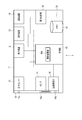
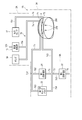
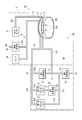
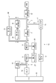
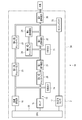
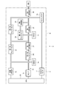
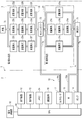
- FIG. 1 is an explanatory diagram schematically showing a configuration of a blood pressure measuring device according to the first embodiment of the present invention.
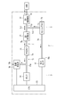
- FIG. 2 is a block diagram schematically showing the configuration of the main body of the blood pressure measuring device.
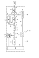
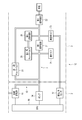
- FIG. 3 is a block diagram showing a configuration of the blood pressure measuring device and an example of its use.
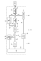
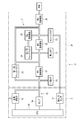
- FIG. 4 is a block diagram showing a configuration of the blood pressure measuring device and an example of its use.
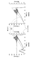
- FIG. 5 is an explanatory diagram showing an example of a change in pressure and a change in injection amount in blood pressure measurement of the same blood pressure measuring device.
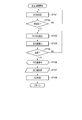
- FIG. 6 is a flow chart showing an example of using the blood pressure measuring device.
- FIG. 7 is an explanatory diagram schematically showing the configuration of the blood pressure measuring device according to the second embodiment of the present invention.
- FIG. 8 is a block diagram showing a configuration of the blood pressure measuring device and an example of its use.
- FIG. 9 is a block diagram showing a configuration of the blood pressure measuring device and an example of its use.
- FIG. 10 is an explanatory diagram schematically showing the configuration of the blood pressure measuring device according to the third embodiment of the present invention.
- FIG. 11 is a block diagram showing a configuration of the blood pressure measuring device and an example of its use.
- FIG. 12 is a block diagram showing a configuration of the blood pressure measuring device and an example of its use.
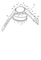
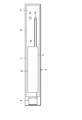
- FIG. 13 is a perspective view showing the configuration of the blood pressure measuring device according to the fourth embodiment of the present invention.
- FIG. 14 is a plan view showing the configuration of the cuff structure and the fluid control unit of the blood pressure measuring device.
- FIG. 15 is an explanatory diagram schematically showing the configuration of the blood pressure measuring device according to the fifth embodiment of the present invention.
- FIG. 16 is an explanatory diagram schematically showing the configuration of the blood pressure measuring device according to the sixth embodiment of the present invention.
- FIG. 17 is an explanatory diagram schematically showing the configuration of the blood pressure measuring device according to the eighth embodiment of the present invention.
- FIG. 18 is an explanatory diagram schematically showing the configuration of the blood pressure measuring device according to the ninth embodiment of the present invention.
- FIG. 19 is an explanatory diagram schematically showing the configuration of the blood pressure measuring device according to the tenth embodiment of the present invention.
- FIG. 20 is an explanatory diagram schematically showing the configuration of the blood pressure measuring device according to the eleventh embodiment of the present invention.
- FIG. 21 is an explanatory diagram schematically showing the configuration of the blood pressure measuring device according to the twelfth embodiment of the present invention.
- FIG. 22 is an explanatory diagram schematically showing a configuration of a modified example of the blood pressure measuring device according to the twelfth embodiment of the present invention.
- FIG. 23 is a cross-sectional view showing an example in which a plurality of flow resistances are arranged in parallel in the configuration of the fluid resistance used in the blood pressure measuring device.
- FIG. 24 is a plan view showing the structure of the orifice film used for the fluid resistance.
- FIG. 25 is a cross-sectional view showing an example in which a plurality of flow rate resistors are arranged in series, which is a configuration of another example of the fluid resistance.
- FIG. 26 is a plan view showing the structure of the orifice film used for the fluid resistance.
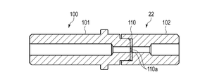
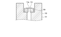
- FIG. 27 is a cross-sectional view showing the configuration of another example of fluid resistance.
- FIG. 28 is an enlarged cross-sectional view showing the configuration of the fluid resistance.
- FIG. 29 is an explanatory diagram schematically showing the configuration of another modification of the blood pressure measuring device according to the twelfth embodiment of the present invention.
- FIG. 1 is an explanatory diagram schematically showing the configuration of the blood pressure measuring device 1 according to the first embodiment of the present invention.
- FIG. 2 is a block diagram schematically showing the configuration of the device main body 2 of the blood pressure measuring device 1.
- FIG. 3 is a block diagram showing the configuration of the blood pressure measuring device 1 and showing an example of the flow of the fluid supplied to the cuffs 71 and 73 in the blood pressure measurement.
- FIG. 4 is a block diagram showing the configuration of the blood pressure measuring device 1 and showing an example of the flow of the fluid in the discharge of the fluid after the blood pressure measurement.
- FIG. 5 is an explanatory diagram showing an example of a change in pressure and a change in injection amount of each of the cuffs 71 and 73 in the blood pressure measurement of the blood pressure measuring device 1.
- the blood pressure measuring device 1 is an electronic blood pressure measuring device worn on a living body.
- the blood pressure measuring device 1 is, for example, an electronic blood pressure measuring device that is attached to a living body 200 such as a wrist and has an aspect of measuring blood pressure from an artery 210 of the living body 200.
- the blood pressure measuring device 1 includes a device main body 2 and a fluid circuit 3.
- the blood pressure measuring device 1 includes at least a fixture 4 such as a belt that fixes the fluid circuit 3 to the living body 200.
- the living body 200 in FIG. 1 shows a wrist, the living body 200 may be an upper arm or the like.
- the device main body 2 includes a case 11, a display device 12, an operating device 13, a pump 14, a flow path section 15, an on-off valve 16, a pressure sensor 17, and a power supply section 18.
- a communication device 19 and a control board 20 are provided.
- the case 11 houses, for example, a display device 12, an operating device 13, a pump 14, a flow path unit 15, an on-off valve 16, a pressure sensor 17, a power supply unit 18, a communication device 19, and a control board 20. Further, the case 11 is formed by exposing a part of the display device 12 so that a part of the display device 12 can be visually recognized from the outside, or by using a transparent material. The case 11 may be configured to accommodate a part of the configuration of the fluid circuit 3.
- the display device 12 is electrically connected to the control board 20.
- the display device 12 is, for example, a liquid crystal display (LCD: Liquid Crystal Display) or an organic electroluminescence display (OELD: Organic Electro Luminescence Display).
- the display device 12 displays various information including the date and time, the blood pressure value such as the systolic blood pressure and the diastolic blood pressure, and the measurement result such as the heart rate according to the control signal from the control board 20.
- the operation device 13 inputs a command from the user.
- the operation device 13 includes a plurality of buttons, a sensor that detects the operation of the buttons, a touch panel of a pressure-sensitive type or a capacitance type provided in the case 11, a display device 12, or the like, and a microphone that receives a command by sound. And so on.
- the operation device 13 is operated by the user to convert a command into an electric signal and output the electric signal to the control board 20.
- the pump 14 is, for example, a piezoelectric pump.
- the pump 14 compresses the fluid and supplies the compressed fluid to the fluid circuit 3 via the flow path portion 15.
- the pump 14 is electrically connected to the control board 20.
- the pump 14 is driven based on a control signal given from the control board 20.
- the fluid any gas or any liquid can be adopted.
- the fluid is air.
- the flow path portion 15 connects the pump 14, the on-off valve 16, and the pressure sensor 17 to the fluid circuit 3.
- the flow path portion 15 is any one of a tube, a pipe, a tank, a hollow portion and a groove formed in the case 11, or a combination thereof.
- the flow path portion 15 forms a flow path from the pump 14 to the secondary side, and a flow path that branches a part of the flow path from the pump 14 to the secondary side and connects to the on-off valve 16.
- Form 15a Further, the flow path portion 15 forms a flow path 15b that connects the on-off valve 16 to the atmosphere. Further, the flow path portion 15 forms a flow path 15c for connecting the pressure sensor 17 to the fluid circuit 3.
- the on-off valve 16 is electrically connected to the control board 20.
- the on-off valve 16 is controlled by the control board 20.
- the on-off valve 16 is opened and closed under the control of the control board 20.
- the on-off valve 16 is connected to the atmosphere by the flow path portion 15 and is switched to the open state to connect the pump 14 and the fluid circuit 3 to the atmosphere.
- the on-off valve 16 is an exhaust valve that opens the secondary side flow path of the pump 14 to the atmosphere. Further, for example, the on-off valve 16 is a rapid exhaust valve in which, for example, the opening degree of the on-off valve 16 or the opening area of the flow path portion 15 is set so that the fluid resistance is as low as possible, and rapid exhaust is possible. .. In each figure, the on-off valve 16 is shown as a quick exhaust valve 16. Such an on-off valve 16 is switched to a closed state when air is supplied to the fluid circuit 3 at the time of blood pressure measurement. Further, the on-off valve 16 is switched from the closed state to the open state by being controlled by the control board 20 when the fluid circuit 3 is exhausted. Further, the on-off valve 16 may be formed so that the opening degree can be adjusted.
- the pressure sensor 17 detects the pressure of the cuff arranged on the secondary side of the fluid circuit 3, and in the present embodiment, the pressure of the sensing cuff 73 described later of the fluid circuit 3.
- the pressure sensor 17 is fluidly connected to the sensing cuff 73 via the flow path portion 15 to detect the pressure in the sensing cuff 73.
- the pressure sensor 17 is electrically connected to the control board 20.
- the pressure sensor 17 outputs an electric signal corresponding to the detected pressure to the control board 20.
- the power supply unit 18 is a power source.
- the power supply unit is, for example, a secondary battery such as a lithium ion battery.
- the power supply unit 18 is electrically connected to the control board 20.
- the power supply unit 18 supplies power to the control board 20.
- the power supply unit 18 supplies electric power for driving to each configuration of the control board 20 and to the display device 12, the operation device 13, the pump 14, the on-off valve 16, the pressure sensor 17, and the communication device 19 via the control board 20. Supply.
- the communication device 19 is configured to be able to transmit and receive information wirelessly or by wire with an external device.
- the communication device 19 transmits, for example, information controlled by the control board 20 and information such as the measured blood pressure value and pulse to an external device, and also receives a software update program or the like from the external device. And send it to the control unit.
- the external device is, for example, an external terminal such as a smartphone, a tablet terminal, a personal computer, or a smart watch.
- the communication device 19 and the external device may be directly connected or may be connected via a network.
- the communication device 19 and an external device may be connected via a mobile communication network such as 4G or 5G or a wireless communication line such as Wimax or Wi-Fi (registered trademark).
- the communication device 19 and the external device may be connected by wireless communication means such as Bluetooth (registered trademark), NFC (Near Filed Communication), and infrared communication.
- the communication device 19 and the external device may be connected via a wired communication line such as a USB (Universal Serial Bus) or a LAN (Local Area Network) connection using a cable. Therefore, the communication device 19 may be configured to include a plurality of communication means such as a wireless antenna and a micro USB connector.
- the control board 20 includes, for example, a board, a storage unit 54, and a control unit 55.
- the control board 20 is configured by mounting a storage unit 54 and a control unit 55 on the board.
- the board is fixed to the case 11.
- the storage unit 54 is a memory mounted on the board.
- the storage unit 54 includes a RAM (Random Access Memory), a ROM (Read Only Memory), and the like.
- the storage unit 54 stores various data.
- the storage unit 54 has program data for controlling the entire blood pressure measuring device 1, the pump 14, and the fluid circuit 3, setting data for setting various functions of the blood pressure measuring device 1, and pressure measured by the pressure sensor 17.
- the calculated data for calculating the blood pressure value and the pulse from the above can be changed and stored in advance.
- the storage unit 54 stores information such as the measured blood pressure value, the measured value such as the pulse, and the pressure value measured by the pressure sensor 17.
- the storage unit 54 can also store various data generated by the measurement processing unit 55a of the control unit 55.
- the control unit 55 includes a single or a plurality of processors mounted on a board.
- the processor is, for example, a CPU (Central Processing Unit).
- the control unit 55 controls the operation of the entire blood pressure measuring device 1 and the operations of the pump 14 and the fluid circuit 3 based on the program stored in the storage unit 54, and executes a predetermined operation (function). Further, the control unit 55 performs a predetermined calculation, analysis, processing, etc. in the control unit 55 according to the read program.
- the control unit 55 is electrically connected to the display device 12, the operating device 13, the pump 14, the on-off valve 16, and each pressure sensor 17, and supplies electric power. Further, the control unit 55 controls the operations of the display device 12, the pump 14, and the on-off valve 16 based on the electric signals output by the operating device 13 and the pressure sensor 17.
- control unit 55 includes a main CPU that controls the operation of the entire blood pressure measuring device 1 and a sub CPU that controls the operation of the fluid circuit 3.
- the control unit 55 may have a configuration in which all of the blood pressure measuring device 1 is performed by one CPU.
- the main CPU obtains a measurement result such as a blood pressure value such as systolic blood pressure and diastolic blood pressure and a heart rate from an electric signal output from the pressure sensor 17, and displays an image signal corresponding to the measurement result to the display device 12. Output.
- the sub CPU drives the pump 14 and the on-off valve 16 to send compressed air to the fluid circuit 3. Further, the sub CPU controls the drive and stop of the pump 14 and the opening and closing of the on-off valve 16 based on the electric signal output from the pressure sensor 17. By controlling the pump 14 and the on-off valve 16, the sub CPU supplies compressed air to the fluid circuit 3 and selectively depressurizes the fluid circuit 3.
- Such a control unit 55 configures a part or all of each function executed by the control unit 55 in terms of hardware by one or a plurality of integrated circuits or the like.
- the control unit 55 has a measurement processing unit 55a.
- the measurement processing unit 55a controls the pump 14 and the on-off valve 16 to supply air to the fluid circuit 3, and based on the pressure of the sensing cuff 73 described later in the fluid circuit 3 detected by the pressure sensor 17, the oshiro Blood pressure is calculated by the metric method.
- the fluid circuit 3 includes a cuff structure 6, a pipe group 7, and a fluid control unit 9.
- the fluid circuit 3 fluidly connects the cuff structure 6 and the fluid control unit 9 by the pipe group 7.
- the air flow is such that the pump 14 side (device body 2 side) is the primary side and the fluid circuit 3 side is the secondary side.
- the on-off valve 16 side (device main body 2 side) is the secondary side, and the fluid circuit 3 side is the primary side.
- the primary side and the secondary side are defined with reference to the air flow direction when air is supplied from the pump 14 to the cuff structure 6 and the pipe group 7. do.
- the cuff structure 6 includes a plurality of cuffs.
- the cuff includes a one- or multi-layered bag-like structure that is wrapped around the wrist or the like of a living body when measuring blood pressure and expands by being supplied with a fluid.
- the bag-shaped structure is one that expands due to a fluid.
- the bag-shaped structure is an air bag.
- the bag-shaped structure is formed, for example, by laminating and welding a pair of sheet members.
- the cuff structure 6 includes a first cuff 71 and a second cuff 73.
- the first cuff 71 is fluidly connected to the pump 14.
- the first cuff 71 is expanded by the air from the pump 14.
- the first cuff 71 is a pressing cuff that presses the second cuff 73 against the living body by expanding.
- the first cuff 71 will be described as the pressing cuff 71.
- the pressing cuff 71 is formed, for example, by stacking a plurality of fluidly connected air bags in the pressing direction of the second cuff 73.
- the second cuff 73 is provided on the secondary side of the first cuff 71.
- the second cuff 73 is expanded by the air from the pump 14.
- the second cuff 73 is arranged in the region where the artery 210 of the living body 200 exists when the blood pressure measuring device 1 is attached to the living body.
- the second cuff 73 is a sensing cuff for calculating blood pressure in blood pressure measurement.
- the second cuff 73 will be described as a sensing cuff 73.
- the sensing cuff 73 is supplied with air and is pressed by the inflated pressing cuff 71 to press the region where the artery 210 of the living body 200 exists via the inflated pressing cuff 71.
- the sensing cuff 73 is pressed toward the living body 200 by the expanded pressing cuff 71.
- the sensing cuff 73 is formed of, for example, one air bag.
- the sensing cuff 73 is fluidly connected to the pressing cuff 71 via the fluid control unit 9.
- the sensing cuff 73 is fluidly connected to the secondary side of the pressing cuff 71 via the fluid control unit 9.
- the pipe group 7 is a set of pipes and hollow portions provided between the sheet members constituting the air bag.
- the tube group 7 may be provided integrally with the cuff structure 6, for example, or may be separated from the cuff structure 6 and connected to the cuff structure 6.
- the tube group 7 fluidly connects the pressing cuff 71, the sensing cuff 73, and the fluid control unit 9. Further, the pipe group 7 is connected to the flow path portion 15.
- the tube group 7 in the configuration in which the fluid control unit 9 has the first fluid resistance 21 and the second fluid resistance 22 will be described.
- the pipe group 7 fluidly connects the pump 14, the on-off valve 16, and the pressing cuff 71 via, for example, the flow path portion 15.
- the tube group 7 fluidly connects the pressure sensor 17 and the sensing cuff 73 via, for example, the flow path portion 15. Further, in the tube group 7, for example, the first fluid resistance 21, the second fluid resistance 22 and the atmosphere are fluidly connected in series to the secondary side of the pressing cuff 71, and the first fluid resistance 21 and the second fluid resistance are connected.
- the sensing cuff 73 is fluidly connected to the 22.
- the tube group 7 includes a first tube 7a, a second tube 7b, a third tube 7c, a fourth tube 7d, and a fifth tube 7e.
- the first pipe 7a is connected to the flow path 15a of the flow path portion 15 and the pressing cuff 71.
- the first pipe 7a connects the pump 14, the on-off valve 16, and the pressing cuff 71 via the flow path portion 15.
- the second pipe 7b is connected to the pressing cuff 71 and the first fluid resistance 21.
- the third pipe 7c is a branch pipe having a branch portion 7c1 in the middle portion from the primary side to the secondary side and branching into two flow paths in the branch portion 7c1.
- the primary side of the third pipe 7c is fluidly connected to the first fluid resistance 21.
- the secondary side of the third pipe 7c and one of the branching pipes 7c2 is connected to the second fluid resistor 22.
- the other pipe portion 7c3, which is the secondary side of the third pipe 7c and branches, is connected to the sensing cuff 73.
- the fourth pipe 7d connects the second fluid resistor 22 and the atmosphere. That is, one end of the fourth pipe 7d is connected to the secondary side of the second fluid resistor 22, and the other end opens to the outside.
- the fifth pipe 7e is connected to the flow path 15c of the flow path portion 15 and the sensing cuff 73.
- the fifth pipe 7e connects the pressure sensor 17 and the sensing cuff 73 via the flow path portion 15.
- the fluid control unit 9 constantly controls the air pressure ratio of the two cuffs 71 and 73 by the fluid resistivity ratio of the two fluid resistors 21 and 22. As shown in FIGS. 1, 4 and 5, the fluid control unit 9 is provided between, for example, the pressing cuff 71 and the sensing cuff 73.
- the fluid control unit 9 includes a first fluid resistance 21 and a second fluid resistance connected in series.
- the fluid control unit 9 applies a pressure difference to the pressure on the primary side of the first fluid resistance 21, the pressure between the first fluid resistance 21 and the second fluid resistance 22, and the pressure on the secondary side of the second fluid resistance 22. Give rise. Due to these pressure differences, the fluid control unit 9 keeps the pressure ratio of the pressing cuff 71 on the primary side of the first fluid resistance 21 and the sensing cuff 73 connected between the first fluid resistance 21 and the second fluid resistance 22 constant. To control.
- the first fluid resistance 21 is a resistance of a passing fluid, or air in the present embodiment.
- the first fluid resistance 21 is, for example, a flow path cross-sectional area smaller than the flow path cross-sectional areas of the primary side and the secondary side of the first fluid resistance 21, that is, the flow path cross-sectional areas of the second pipe 7b and the third pipe 7c.
- the first fluid resistance 21 is, for example, an orifice.
- the first fluid resistance 21 is supplied to the secondary side of the first fluid resistance 21 with respect to the flow rate of air supplied to the pressing cuff 71 by narrowing the flow path on the flow path from the pressing cuff 71 to the sensing cuff 73. Reduce the flow rate of air.
- the second fluid resistance 22 is a resistance of a passing fluid, or air in the present embodiment.
- the second fluid resistance 22 is, for example, a flow path cross-sectional area smaller than the flow path cross-sectional areas of the primary side and the secondary side of the second fluid resistance 22, that is, the flow path cross-sectional areas of the second pipe 7b and the third pipe 7c.
- the second fluid resistor 22 is, for example, an orifice.
- the second fluid resistance 22 becomes the first fluid resistance 21 and the second fluid resistance 22 by narrowing the flow path from the flow path between the first fluid resistance 21 and the second fluid resistance 22 to the air.
- the flow rate of the air supplied to the secondary side (atmosphere) of the second fluid resistance 22 is reduced from the flow rate of the supplied air. That is, when a part of the air supplied to the flow path between the first fluid resistance 21 and the second fluid resistance 22 flows to the sensing cuff 73 and the atmosphere, the second fluid resistance 22 is the air to the atmosphere side. It becomes a flow resistance and controls the flow rate of the air injected into the sensing cuff 73 and the flow rate of the air flowing out to the atmosphere.
- Such a fluid resistivity ratio of the first fluid resistance 21 and the second fluid resistance 22 can be obtained by, for example, experimentally obtaining the relationship between the resistance ratio of the first fluid resistance 21 and the second fluid resistance 22 and the measurement error.
- the optimum fluid resistivity is set.
- the blood pressure is measured multiple times with the fluid resistance ratios of the first fluid resistance 21 and the second fluid resistance 22 as different fluid resistance ratios, and the blood pressure error of each is obtained.
- the blood pressure error when the second fluid resistance ratio is 1 is about.
- the first fluid resistance 21 and the second fluid resistance 22 which are the fluid resistance ratios are set.
- FIG. 3 the air flow is indicated by an arrow, and the flow path in which each valve is closed is indicated by X.
- a part of the air supplied to the flow path between the first fluid resistance 21 and the second fluid resistance 22 is injected into the sensing cuff 73 and into the flow path between the first fluid resistance 21 and the second fluid resistance 22. Other than the supplied air, it passes through the second fluid resistor 22 and is exhausted to the atmosphere. At this time, the flow rate of the air flowing to the sensing cuff 73 and the atmosphere of the air supplied to the flow path between the first fluid resistance 21 and the second fluid resistance 22 changes depending on the resistance of the second fluid resistance 22. ..
- FIG. 5 (conventional technique) is an example of a change in pressure of the blood pressure measuring device according to the prior art.
- an on-off valve is provided in each cuff, each on-off valve is opened and closed by the measurement processing unit 55a, and the pressure of each cuff is controlled by a pressure sensor connected to each cuff.
- the fluid control unit 9 of the present embodiment uses the partial pressures of the first fluid resistance 21 and the second fluid resistance, so that the supplied air passes through the first fluid resistance 21 and the second fluid resistance 22.
- the pressure ratio becomes constant from the start of air supply to the stop of air supply.
- the pump 14 is stopped by the measurement processing unit 55a of the control unit 55, and the on-off valve 16 is opened.
- the on-off valve 16 side of the pressing cuff 71 is connected to the atmosphere, so that the air in the pressing cuff 71 flows to the on-off valve 16 side.
- the air in the sensing cuff 73 is exhausted to the atmosphere via the second fluid resistor 22.
- the pressure of the pressing cuff 71 decreases, and when the pressure of the pressing cuff 71 becomes lower than the pressure of the sensing cuff 73, the air of the sensing cuff 73 passes through the second fluid resistor 22. In addition to exhausting to the atmosphere, it moves to the pressing cuff 71 through the first fluid resistor 21 and is exhausted to the atmosphere from the on-off valve 16. In this way, the fluid circuit 3 is exhausted.
- the user operates the operating device 13 to give a command to start blood pressure measurement.
- the operating device 13 outputs an electric signal to the control unit 55 as a command to start blood pressure measurement.
- the measurement processing unit 55a switches the on-off valve 16 to the closed state, starts driving the pump 14, and pressurizes the pressing cuff 71 and the sensing cuff 73. (Step ST101).
- the measurement processing unit 55a determines whether or not the pressure measured by the pressure sensor 17 is a predetermined pressure (step ST102).
- the predetermined pressure is the pressure of the sensing cuff 73 whose blood pressure can be measured by the sensing cuff 73, and is stored in the storage unit 54 in advance.
- the measurement processing unit 55a When the pressure of the sensing cuff 73 is not a predetermined pressure (NO in step ST102), the measurement processing unit 55a continues to drive the pump 14. When the pressure of the sensing cuff 73 reaches a predetermined pressure (YES in step ST102), the measurement processing unit 55a stops the pump 14 and stops the supply of air to the pressing cuff 71. Further, the measurement processing unit 55a switches the on-off valve 16 to the open state and starts depressurizing the pressing cuff 71 (step ST103). At this time, the measurement processing unit 55a gently depressurizes the pressing cuff 71 by adjusting the opening degree of the on-off valve 16 or repeatedly switching the opening and closing of the on-off valve 16.
- the measurement processing unit 55a calculates the blood pressure value from the pressure measured by the pressure sensor 17 (step ST104). Next, the measurement processing unit 55a determines whether or not the calculated value may be determined as the blood pressure value (step ST105). The threshold value of whether or not the calculated value may be determined as the blood pressure value is stored in advance in the storage unit 54. Further, the threshold value for determining the blood pressure value is appropriately set according to the detected blood pressure value, the pressure of the sensing cuff 73, and the like. If the calculated value cannot be determined as the blood pressure value (NO in step ST105), the measurement processing unit 55a continues to reduce the pressure of the pressing cuff 71 (step ST103).
- the measurement processing unit 55a displays the blood pressure value on the display device 12 (step ST106) and records the measured blood pressure value in the storage unit 54 (YES in step ST105). (Store) (step ST107). Next, the measurement processing unit 55a maximizes the opening degree of the on-off valve 16 or opens the on-off valve 16 to exhaust the pressing cuff 71 and the sensing cuff 73 (step ST108). Then, the measurement processing unit 55a finishes the blood pressure measurement, waits until the next command to start the blood pressure measurement, and when the command to start the blood pressure measurement is received, returns to step ST101 again and starts the blood pressure measurement.
- the fluid circuit 3 is provided with the first fluid resistance 21 and the second fluid resistance 22 on the secondary side of the pressing cuff 71, and the first fluid resistance 21 and the second fluid A sensing cuff 73 is connected to the flow path between the resistors 22, and the secondary side of the second fluid resistor 22 is connected to the atmosphere.
- the pressure ratio of the pressing cuff 71 and the sensing cuff 73 becomes constant. Therefore, in blood pressure measurement, the step of injecting air by the measurement processing unit 55a of the control unit 55 becomes unnecessary, and the measurement time is shortened. Therefore, the influence of artifacts such as body movement is eliminated, and the blood pressure measuring device 1 is improved in robustness in actual use.
- the pressure difference between the pressing cuff 71 and the sensing cuff 73 can be set by the fluid resistivity ratio of the first fluid resistance 21 and the second fluid resistance 22. Therefore, in the first fluid resistance 21 and the second fluid resistance 22, the pressing cuff 71 and the sensing cuff 73 expand at a suitable pressure ratio only by passing air. Therefore, the blood pressure measuring device 1 does not require a component electrically controlled by a control unit 55 or the like other than the pump 14 and the on-off valve 16 in order to make the pressure ratio of the pressing cuff 71 and the sensing cuff 73 constant.
- the blood pressure measuring device 1 can simplify the control in blood pressure measurement and reduce the power consumption. Further, it is not necessary to arrange the first fluid resistance 21 and the second fluid resistance 22 that do not require electrical control on the device main body 2, and by providing the fluid control unit 9 outside the device main body 2, the device main body 2 can be provided. Miniaturization is possible.
- each on-off valve is provided on the primary side of the pressing cuff 71 and the sensing cuff 73 of the conventional blood pressure measuring device and each on-off valve is controlled based on the detected pressure.
- the blood pressure measuring device 1 can keep the pressure ratio constant from the start of driving the pump 14. Therefore, the time from the start of driving the pump 14 to the measurement of blood pressure can be shortened.
- the air of the sensing cuff 73 is exhausted to the atmosphere through the first fluid resistance 21, the pressing cuff 71 and the on-off valve 16, and is exhausted to the atmosphere through the second fluid resistance 22. It is done by two channels that exhaust to. Therefore, even if the first fluid resistance 21 and the second fluid resistance 22 are used, the decrease in the exhaust efficiency of the sensing cuff 73 can be suppressed as much as possible.
- the blood pressure measuring device 1 can reduce the load on the living body due to the compression of the living body after the blood pressure measurement is completed.
- the first fluid resistance 21 and the second fluid resistance 22 are provided on the secondary side of the pressing cuff 71, and the first fluid resistance 21 and the second fluid resistance 21 and the second fluid resistance 22 are provided.
- a sensing cuff 73 was connected to the flow path between the fluid resistors 22, and the secondary side of the second fluid resistor 22 was connected to the atmosphere. Therefore, the blood pressure measuring device 1 can keep the pressure ratio of the pressing cuff 71 and the sensing cuff 73 constant.
- FIG. 7 is an explanatory diagram schematically showing the configuration of the blood pressure measuring device 1A according to the second embodiment.
- FIG. 8 is a block diagram showing the configuration of the blood pressure measuring device 1A and showing an example of the flow of the fluid supplied to the cuffs 71 and 73 in the blood pressure measurement.
- FIG. 9 is a block diagram showing the configuration of the blood pressure measuring device 1 and showing an example of the flow of the fluid in the discharge of the fluid after the blood pressure measurement.
- the same components as those of the blood pressure measuring device 1 according to the first embodiment are designated by the same reference numerals, and detailed description thereof will be omitted.
- the blood pressure measuring device 1A is an electronic blood pressure measuring device to be attached to the living body 200, similarly to the blood pressure measuring device 1. As shown in FIGS. 7 to 9, the blood pressure measuring device 1A includes a device main body 2A and a fluid circuit 3A.
- the fluid circuit 3A includes a cuff structure 6, a pipe group 7, and a fluid control unit 9A.
- the fluid control unit 9A includes a first fluid resistance 21 and a second fluid resistance connected in series, and a valve 23 provided in parallel with the first fluid resistance 21.
- the valve 23 opens when the pressure on the primary side is lower than the pressure on the secondary side. Specifically, the valve 23 is closed when the pressure on the pressing cuff 71 side is equal to or higher than the pressure on the flow path (sensing cuff 73) side between the first fluid resistance 21 and the second fluid resistance 22, and the pressing cuff 71 is closed. It opens when the pressure on the side becomes lower than the pressure on the flow path side between the first fluid resistance 21 and the second fluid resistance 22. Such a valve 23 is always closed when air is supplied to the pressing cuff 71 and the sensing cuff 73 during blood pressure measurement, for example. Further, the valve 23 opens when the pressure of the pressing cuff 71 becomes lower than the pressure of the sensing cuff 73.
- the valve 23 is, for example, a check valve. In each figure, the valve 23 is shown as a check valve 23.
- the cracking pressure of the valve 23 is set to a pressure suitable for exhausting the pressing cuff 71 and the sensing cuff 73.
- the cracking pressure of the valve 23 is set to 0 mmHg so that the valve 23 opens when the pressure of the pressing cuff 71 falls below the pressure of the sensing cuff 73.
- the valve 23 has a configuration that can prevent the air of the pressing cuff 71 from flowing to the sensing cuff 73 side at the time of exhausting, and opens when the pressure on the primary side is lower than the pressure on the secondary side. However, if there is virtually no air flow from the pressing cuff 71 to the sensing cuff 73 in the exhaust of the fluid circuit 3A, the valve 23 will open when the pressure on the primary side is slightly lower than the pressure on the secondary side. It may be set to (for example, 15 mmHg).
- the second pipe 7b has a branch portion 7b1 in the middle portion from the primary side to the secondary side, and the branch portion 7b1 has two branches. It is a branch pipe that branches into a flow path.
- the primary side of the second pipe 7b is fluidly connected to the pressing cuff 71.
- the secondary side of the second pipe 7b and one of the branching pipes 7b2 is connected to the first fluid resistance 21.
- the other pipe portion 7b3, which is the secondary side of the second pipe 7b and branches, is connected to the valve 23.
- the third pipe 7c is a branch pipe having a branch portion 7c1 in the middle portion from the primary side to the secondary side and branching into three flow paths at the branch portion 7c1.
- the primary side of the third pipe 7c is fluidly connected to the first fluid resistance 21.
- the first pipe portion 7c2, which is the secondary side of the third pipe 7c and branches into three, is connected to the second fluid resistor 22.
- the second pipe portion 7c3, which is the secondary side of the third pipe 7c and branches into three, is connected to the sensing cuff 73.
- the third pipe portion 7c4, which is the secondary side of the third pipe 7c and branches into three, is connected to the secondary side of the valve 23.
- a part of the air supplied to the flow path between the first fluid resistance 21 and the second fluid resistance 22 is injected into the sensing cuff 73 and into the flow path between the first fluid resistance 21 and the second fluid resistance 22. Other than the supplied air, it passes through the second fluid resistor 22 and is exhausted to the atmosphere. At this time, the flow rate of the air flowing to the sensing cuff 73 and the atmosphere of the air supplied to the flow path between the first fluid resistance 21 and the second fluid resistance 22 changes depending on the resistance of the second fluid resistance 22. ..
- the pressure ratio between the pressure of the pressing cuff 71 and the pressure of the sensing cuff 73 is the pressure of air from the start of air supply by the pump 14. It will be constant until the supply is stopped.
- the pump 14 is stopped by the measurement processing unit 55a of the control unit 55, the on-off valve 16 is opened, and the on-off valve 16 side of the pressing cuff 71 is opened. Since it is connected to the atmosphere, the air in the pressing cuff 71 flows to the on-off valve 16 side. Further, the air in the sensing cuff 73 is exhausted to the atmosphere via the second fluid resistor 22.
- the air of the sensing cuff 73 is added to the exhaust to the atmosphere via the second fluid resistance 22 and the second 1 It moves to the pressing cuff 71 through the fluid resistance 21, and is exhausted from the on-off valve 16 to the atmosphere.
- the valve 23 opens, the flow path passing through the valve 23 becomes a bypass path, and the exhaust speed of the sensing cuff 73 increases. Then, the exhaust of the pressing cuff 71 and the sensing cuff 73 proceeds, and the pressure of the pressing cuff 71 and the sensing cuff 73 becomes atmospheric pressure. As described above, in the exhaust of the fluid circuit 3A, the pressing cuff 71 is rapidly exhausted with priority over the sensing cuff 73. Then, in the fluid circuit 3A, when the pressure of the pressing cuff 71 becomes lower than the pressure of the sensing cuff 73, the valve 23 opens and the pressing cuff 71 and the sensing cuff 73 are rapidly exhausted. As described above, the fluid circuit 3A is exhausted.
- the same effect as that of the blood pressure measuring device 1 according to the first embodiment described above is obtained.
- the valve 23 opens when the pressure of the sensing cuff 73 is higher than the pressing cuff 71 at the time of exhaust, and the air of the sensing cuff 73 pushes the first valve 23. It passes through a bypass path that does not pass through the fluid resistors 21 and 22, and is exhausted to the atmosphere through the pressing cuff 71. Therefore, even if the two fluid resistors 21 and 22 are provided, the sensing cuff 73 can be exhausted through the bypass path in which the fluid resistors are not arranged. Therefore, even if the blood pressure measuring device 1 has the fluid resistances 21 and 22, it is possible to prevent the exhaust speed of the sensing cuff 73 from decreasing.
- such a configuration of the fluid control unit 9A is effective when the capacity of the pump 14 is low. That is, when the capacity of the pump 14 is low and the inflow to the atmospheric pressure is large, the first fluid resistance 21 and the second fluid resistance 22 arranged between the pressing cuff 71 and the opening to the atmosphere so that the flow rate is equal to or less than a predetermined flow rate.
- the fluid resistance value value of the first fluid resistance + value of the second fluid resistance
- the fluid resistance value (value of the first fluid resistance + value of the second fluid resistance) is set to be large. Therefore, the flow rate decreases when the air of the sensing cuff 73 passes through the first fluid resistance 21 and the second fluid resistance 22 at the time of exhausting. Therefore, the exhaust speed of the sensing cuff 73 decreases.
- a bypass path like the fluid control unit 9A, rapid exhaust of the sensing cuff 73 becomes possible.
- the first fluid resistance 21 and the second fluid resistance 22 are provided on the secondary side of the pressing cuff 71, and the first fluid resistance 21 and the second fluid resistance 21 and the second fluid resistance 22 are provided.
- a sensing cuff 73 was connected to the flow path between the fluid resistors 22, and the secondary side of the second fluid resistor 22 was connected to the atmosphere. Therefore, the blood pressure measuring device 1A can keep the pressure ratio of the pressing cuff 71 and the sensing cuff 73 constant.
- FIG. 10 is an explanatory diagram schematically showing the configuration of the blood pressure measuring device 1B according to the third embodiment.
- FIG. 11 is a block diagram showing the configuration of the blood pressure measuring device 1B and showing an example of the flow of the fluid supplied to the cuffs 71 and 73 in the blood pressure measurement.
- FIG. 12 is a block diagram showing the configuration of the blood pressure measuring device 1 and showing an example of the flow of the fluid in the discharge of the fluid after the blood pressure measurement.
- the same components as those of the blood pressure measuring device 1A according to the second embodiment are designated by the same reference numerals, and detailed description thereof will be omitted.
- the blood pressure measuring device 1B is an electronic blood pressure measuring device to be attached to the living body 200, similarly to the blood pressure measuring device 1A. As shown in FIGS. 10 and 12, the blood pressure measuring device 1B includes a device main body 2 and a fluid circuit 3B.
- the fluid circuit 3B includes a cuff structure 6, a pipe group 7, and a fluid control unit 9B.
- the fluid control unit 9B includes a first fluid resistance 21 and a second fluid resistance connected in series, a first valve 23 provided in parallel with the first fluid resistance 21, and parallel to the first fluid resistance 21. It includes a second valve 24 and a third fluid resistor 25 connected in parallel with the first valve 23.
- the first valve 23 is the valve 23 used in the blood pressure measuring device 1A of the second embodiment described above.
- the second valve 24 opens when the pressure on the primary side is higher than the pressure on the secondary side. Specifically, the second valve 24 opens when the pressure on the pressing cuff 71 side becomes equal to or higher than the pressure on the sensing cuff 73 side. Such a second valve 24 opens, for example, when the pressure of the pressing cuff 71 becomes a cracking pressure higher than the pressure of the sensing cuff 73 by a predetermined pressure.
- the second valve 24 is, for example, a check valve.
- the third fluid resistance 25 is the resistance of the passing air.
- the third fluid resistance 25 is, for example, a flow path cross-sectional area smaller than the flow path cross-sectional areas of the primary side and the secondary side of the third fluid resistance 25, that is, the flow path cross-sectional areas of the third pipe 7c and the fourth pipe 7d.
- the third fluid resistor 25 is, for example, an orifice.
- the cracking pressure of the second valve 24 and the fluid resistance value of the third fluid resistance 25 can control the pressure ratio of the pressing cuff 71 and the sensing cuff 73 at the time of blood pressure measurement, and quickly determine the pressure of the sensing cuff 73.
- the pressure is set to a pressure that can be.
- the second pipe 7b has a branch portion 7b1 in the middle from the primary side to the secondary side. It is a branch pipe that has and branches into three flow paths in the branch portion 7b1.
- the primary side of the second pipe 7b is fluidly connected to the pressing cuff 71.
- the three branching pipe portions 7b2, 7b3, and 7b4, which are the secondary side of the second pipe 7b, are connected to the first fluid resistance 21, the first valve 23, and the second valve 24, respectively.
- the third pipe 7c is a branch pipe having a branch portion 7c1 in the middle portion from the primary side to the secondary side and branching into four flow paths at the branch portion 7c1.
- the primary side of the third pipe 7c is fluidly connected to the first fluid resistance 21.
- the pipe portions 7c2, 7c3, 7c4, 7c5, which are the secondary side of the third pipe 7c and branch into four, are the second fluid resistance 22, the sensing cuff 73, the secondary side of the first valve 23, and the second pipe portion. 3 Connected to the fluid resistor 25.
- the pipe group 7 includes a sixth pipe 7f connecting the second valve 24 and the third fluid resistance 25.
- the fluid circuit 3B when the on-off valve 16 is closed by the measurement processing unit 55a of the control unit 55 and the driving of the pump 14 is started at the time of blood pressure measurement, the fluid circuit 3B is first supplied to the pressing cuff 71. Since air is supplied to the pressing cuff 71 first, the first valve 23 closes when the pressure on the primary side becomes higher than the pressure on the secondary side. Further, the second valve 24 opens when the pressure on the primary side becomes higher than the pressure on the secondary side by a predetermined value (for example, 150 mmHg) or more.
- a predetermined value for example, 150 mmHg
- a part of the air supplied to the pressing cuff 71 passes through the first fluid resistance 21 and the third fluid resistance 25, and is between the first fluid resistance 21, the third fluid resistance 25, and the second fluid resistance 22. It is supplied to the flow path.
- a part of the air supplied to the pressing cuff 71 corresponding to the resistance values of the first fluid resistance 21 and the third fluid resistance is supplied to the flow path between the first fluid resistance 21 and the second fluid resistance 22. Will be done.
- a part of the air supplied to the flow path between the first fluid resistance 21 and the third fluid resistance 25 and the second fluid resistance 22 is injected into the sensing cuff 73, and the first fluid resistance 21 and the third fluid resistance 21 are used.
- the air passes through the second fluid resistance 22 and is exhausted to the atmosphere.
- the sensing cuff 73 and the atmosphere are each. The flow rate of air flowing through changes.
- the pressure ratio between the pressure of the pressing cuff 71 and the pressure of the sensing cuff 73 is determined by the pump 14.
- the pressure of the pressing cuff 71 and the sensing cuff 73 rises constantly from the start of air supply.
- the pump 14 is stopped by the measurement processing unit 55a of the control unit 55, the on-off valve 16 is opened, and the on-off valve 16 side of the pressing cuff 71 is opened. Since it is connected to the atmosphere, the air in the pressing cuff 71 flows to the on-off valve 16 side. Further, the air in the sensing cuff 73 is exhausted to the atmosphere via the second fluid resistor 22.
- the second valve 24 closes and the air of the sensing cuff 73 becomes the first. 2
- the first valve 23 opens, and the air of the sensing cuff 73 moves to the pressing cuff 71 via the first valve 23. In this way, the fluid circuit 3 is exhausted.
- the fluid control unit 9B includes a second valve 24 and a third fluid resistor 25 arranged in series with the first fluid resistor 21.
- the blood pressure measuring device 1B can reduce the differential pressure between the pressing cuff 71 and the sensing cuff 73 at the time of blood pressure measurement, and can improve the rate of increase of the pressure of the sensing cuff 73 to a predetermined pressure. Further, the capacity of the pump 14 can be reduced.
- the blood pressure measuring device 1B can reduce the differential pressure between the pressing cuff 71 and the sensing cuff 73 by the second valve 24 and the third fluid resistance 25 provided in parallel with the first fluid resistance 21. Therefore, the blood pressure measuring device 1B can shorten the time for raising the sensing cuff 73 to the pressure required for blood pressure measurement without requiring the pump 14 to have a high capacity.
- the blood pressure measuring device 1C according to the fourth embodiment is an example in which the blood pressure measuring device 1B according to the third embodiment described above is applied to a wearable type blood pressure measuring device worn on the wrist 200 as a living body.
- the same components as those of the blood pressure measuring device 1B according to the third embodiment described above are designated by the same reference numerals, and detailed description thereof will be omitted.
- the blood pressure measuring device 1C is arranged between the device main body 2, the fluid circuit 3B, the belt 4 which is a fixture for fixing the device main body 2 to the wrist, the belt 4, and the wrist 200. Carla 5 and.
- the case 11 of the device main body 2 includes an outer case 31 and a windshield 32 that covers an opening on the side opposite to the wrist 200 side (outer side) of the outer case 31. Further, the case 11 includes a back cover provided on the wrist 200 side inside the outer case 31.
- the outer case 31 is formed in a cylindrical shape.
- the outer case 31 includes a pair of lugs 31a provided at symmetrical positions in the circumferential direction of the outer peripheral surface, and a spring rod 31b provided between the two pairs of lugs 31a, respectively.
- the windshield 32 is, for example, a circular glass plate. Further, a base portion for supporting each component is provided in the outer case 31.
- the display device 12 is arranged on the base of the outer case 31 and directly below the windshield 32.
- the operation device 13 is configured to be able to input a command from the user.
- the operating device 13 includes a plurality of buttons 41 provided on the case 11, a sensor for detecting the operation of the buttons 41, and a touch panel 43 provided on the display device 12 or the windshield 32.
- the operation device 13 converts a command into an electric signal by being operated by the user.
- the sensor and the touch panel 43 are electrically connected to the control board 20, and output an electric signal to the control board 20.
- the belt 4 includes a first belt 61 provided on one pair of lugs 31a and a spring rod 31b, and a second belt 62 provided on the other pair of lugs 31a and a spring rod 31b.
- the belt 4 is wrapped around the wrist 200 via the carla 5.
- the connector is a buckle 61b included in the first belt 61.
- the first belt 61 is a so-called parent and is configured in a band shape that can be connected to the second belt 62. As shown in FIG. 13, the first belt 61 has a belt portion 61a and a buckle 61b. The belt portion 61a is formed in a band shape. The belt portion 61a is made of an elastically deformable resin material. Further, the belt portion 61a has a flexible sheet-like insert member inside which expansion and contraction of the belt portion 61a in the longitudinal direction is suppressed.
- the belt portion 61a is provided with a spring rod 31b at one end and a buckle 61b at the other end. At one end of the first belt 61, the provided spring rod 31b is arranged between the pair of lugs 31a, so that the first belt 61 is rotatably held by the outer case 31.
- the second belt 62 is a so-called sword tip and is formed in a band shape.
- the second belt 62 is made of an elastically deformable resin material. Further, the second belt 62 has, for example, a sheet-like insert member having flexibility and suppressing expansion and contraction of the second belt 62 in the longitudinal direction.
- the second belt 62 is fixed to the buckle 61b.
- the second belt 62 is provided with a spring rod 31b at one end.
- the spring rod 31b provided at one end of the second belt 62 between the pair of lugs 31a, the second belt 62 is rotatably held by the outer case 31.
- the first belt 61 and the second belt 62 are integrally connected by a buckle 61b, and together with the outer case 31, it becomes an annular shape that follows the circumferential direction of the wrist 200.
- the belt 4 forms an annular shape that follows the circumferential direction of the wrist, thereby pressing the carla 5 and elastically deforming the carla 5 so as to follow the circumferential direction of the wrist of the wearer of the blood pressure measuring device 1B.
- the carla 5 is formed in a band shape that curves along the circumferential direction of the wrist 200.
- the carla 5 is formed so that one end and the other end are separated from each other.
- the outer surface on one end side of the carla 5 is fixed to the back cover side of the device main body 2, or is integrally formed with the back cover or the base of the device main body 2.
- the carla 5 is arranged, for example, at a position where one end and the other end protrude toward one side of the wrist 200 with respect to the device main body 2.
- the carla 5 is separated from each other by a predetermined distance, and one end and the other end are adjacent to each other.
- the carla 5 is made of, for example, a resin material.
- Such a carla 5 is fixed to the outer case 31 with one end and the other end facing the second belt 62 of the belt 4. Further, the carla 5 has a cuff structure 6 facing the palm side of the wrist 200 by at least the position facing the palm side of the wrist 200 being curved along the palm side of the wrist 200 in the circumferential direction. , Hold in a curved state following the shape of the palm side of the wrist 200.
- the carla 5 has a hardness having flexibility and shape retention.
- “flexibility” means that the shape is deformed in the radial direction when an external force of the belt 4 is applied to the carla 5.
- flexibility means that when the carla 5 is pressed by the belt 4, the shape of the side view is deformed so as to be close to the wrist, follow the shape of the wrist, or follow the shape of the wrist.
- the shape-retaining property means that the carla 5 can maintain a preformed shape when no external force is applied.
- the shape retention means that in the present embodiment, the shape of the carla 5 can be maintained to be curved along the circumferential direction of the wrist.
- the cuff structure 6 is arranged on the inner peripheral surface of the carla 5.
- the cuff structure 6, the pipe group 7, and the fluid control unit 9B are integrally formed.
- the fluid circuit 3 is configured by integrally incorporating the pipe group 7 and the fluid control unit 9B into a part of the cuff structure 6.
- the cuff structure 6 includes a pressing cuff 71, a sensing cuff 73, and a fluid control unit 9B, as shown in FIGS. 13 and 14.
- FIG. 14 is a developed view showing the configurations of the carla 5 and the cuff structure 6.
- the cuff structure 6 is laminated and fixed in the order of the pressing cuff 71 and the sensing cuff 73 from the inner peripheral surface of the carla 5 toward the wrist side on the inner peripheral surface of the wrist of the carla 5 on the palm side.
- the cuff structure 6 has, for example, a back plate 72 that supports the sensing cuff 73 between the pressing cuff 71 and the sensing cuff 73.
- the back plate 72 is formed to have a length that covers the palm side of the wrist 200.
- the back plate 72 transmits the pressing force from the pressing cuff 71 to the main surface of the sensing cuff 73 on the back plate 72 side while following the shape of the wrist.
- the pressing cuff 71 is set to, for example, substantially the same length as the length of the carla 5 in the longitudinal direction.
- the pressing cuff 71 includes a plurality of, for example, a two-layer air bag 81 and a connecting portion 84 provided on one end side in the longitudinal direction.
- the pressing cuff 71 is provided with a fluid control unit 9B on the other end side in the longitudinal direction.
- the air bag 81 is a bag-shaped structure.
- the plurality of air bags 81 are laminated and fluidly communicate with each other in the stacking direction.
- the air bag 81 is formed in the shape of a rectangular bag that is long in one direction.
- the width of the air bag 81 in the lateral direction is set to be the same as or slightly smaller than the width of the carla 5 in the lateral direction.
- the air bag 81 is formed by, for example, combining two sheet members and welding them into a rectangular frame long in one direction by heat. Further, in the two-layer air bag 81, the two air bags 81 are welded by heat and combined integrally, or the air bags 81 are welded after welding the opposing sheet members of the adjacent air bags 81. It is composed by forming.
- connection portion 84 is, for example, a nipple.
- the connecting portion 84 projects from the air bag 81.
- the connecting portion 84 is a first pipe 7a connected to the flow path portion 15.
- the sensing cuff 73 is set to a length that can be placed in the area where the wrist artery exists, for example.
- the sensing cuff 73 faces the region where the wrist artery exists when the blood pressure measuring device 1B is worn on the wrist.
- the artery is a radial artery and / or an ulnar artery.
- the sensing cuff 73 expands to compress the area where the arteries on the palm side of the wrist are located.
- the sensing cuff 73 is pressed toward the wrist by the expanded pressing cuff 71.
- the sensing cuff 73 includes one air bag 91, a flow path body 92 communicating with the air bag 91, and a connecting portion 93 provided at the tip of the flow path body 92.
- Such a sensing cuff 73 is configured by integrally welding two sheet members.
- the air bag 91 is formed in a rectangular shape that is long in one direction.
- the air bag 91 is set to a length that can be arranged in the region where the wrist artery exists, for example.
- the air bag 91 is formed by, for example, combining two sheet members long in one direction and welding them in a rectangular frame shape long in one direction by heat.
- the flow path body 92 is integrally provided on a part of one edge of the air bag 91 in the longitudinal direction.
- the flow path body 92 is provided at an end portion of the air bag 91 near the device main body 2.
- the flow path body 92 is formed, for example, in a width smaller than the width in the lateral direction of the air bag 91 and in a long shape in one direction, and the tip is formed in a circular shape.
- the flow path body 92 has a connecting portion 93 at the tip thereof.
- the flow path body 92 is configured by heat-welding the two sheet members in a long frame shape in one direction with the connecting portion 93 arranged on the two sheet members.
- the air bag 91 is configured such that a part of the welded portion that welds the two sheet members in a rectangular frame shape is non-welded and is continuous with the welded portion that forms the flow path body 92. And the flow path body 92 is fluidly continuous.
- connection portion 93 is, for example, a nipple.
- the connecting portion 93 is provided at the tip of the flow path body 92. Further, the tip of the connecting portion 93 is exposed to the outside from the seat member on the side facing the carla 5 among the two seat members constituting the flow path body 92.
- the connecting portion 93 is connected to the flow path portion 15.
- Such a flow path body 92 and a connection portion 93 are connected to the flow path portion 15 via the connection portion 93, and constitute a fifth pipe 7e that connects the air bag 91 and the pressure sensor 17.
- the pressing cuff 71 includes the first pipe 7a of the pipe group 7, and the sensing cuff 73 includes the fifth pipe 7e.
- the fluid control unit 9B is arranged, for example, on the inner surface of the carla 5 and at the end of the palm side of the wrist.
- the fluid control unit 9B is integrally formed at the ends of the pressing cuff 71 and the sensing cuff 73.
- the fluid control unit 9B is integrally formed at the end of the pressing cuff 71, and a part thereof is fluidly connected to the sensing cuff 73.
- the fluid control unit 9B includes the second pipe 7b, the third pipe 7c, the fourth pipe 7d, the first fluid resistance 21, the second fluid resistance 22, the first valve 23, and the second valve 24.
- a third fluid resistor 25 includes a second pipe 7b, a third pipe 7c, a fourth pipe 7d, a first fluid resistance 21, a second fluid resistance 22, a first valve 23, a second valve 24, and the like.
- the third fluid resistor 25 is integrally formed.
- the second pipe 7b, the third pipe 7c, and the fourth pipe 7d are formed by, for example, a part of a pair of seat members constituting one air bag 81 of the pressing cuff 71.
- the second pipe 7b, the third pipe 7c, and the fourth pipe 7d do not weld the regions constituting the second pipe 7b, the third pipe 7c, and the fourth pipe 7d when welding the pair of seat members. Is a gap formed between a pair of seat members.
- the first fluid resistance 21, the second fluid resistance 22, the first valve 23, the second valve 24, and the third fluid resistance 25 are a pair of seat members constituting the second pipe 7b, the third pipe 7c, and the fourth pipe 7d. It is placed in the gap between them.
- the secondary side pipe portion 7c3 of the merging portion 7c1 of the third pipe 7d is connected to the sensing cuff 73.
- the blood pressure measuring device 1C configured in this way has the same effect as the blood pressure measuring device 1B according to the third embodiment described above.
- the blood pressure measuring device 1C includes a second tube 7b, a third tube 7c, a fourth tube 7d, a first fluid resistance 21, a second fluid resistance 22, a first valve 23, a second valve 24, and a third fluid resistance.
- the 25 is integrally formed to form the fluid control unit 9B, which is integrally connected to the end portions of the pressing cuff 71 and the sensing cuff 73. Further, the fluid control unit 9B is configured to be arranged at the end of the carla 5.
- Such a blood pressure measuring device 1C has a configuration that can be integrally arranged with the pressing cuff 71 and the sensing cuff 73 on the carla 5, it is not necessary to arrange the fluid control unit 9B on the device main body 2, and the device main body 2 does not need to be arranged. Miniaturization is possible. In addition, since it is arranged at the end of the carla 5, it is possible to prevent the fluid control unit 9B from obstructing the blood pressure measurement at the time of blood pressure measurement.
- the present invention is not limited to the above-described embodiment.
- the blood pressure measuring devices 1, 1A, 1B, and 1C according to each embodiment, the examples in which the fluid circuits 3, 3A, and 3B are arranged outside the device main body 2 have been described, but the present invention is not limited thereto. ..
- the blood pressure measuring devices 1, 1A, and 1B may be configured to accommodate a part of the fluid circuits 3, 3A, and 3B in the device main body 2.
- the first fluid resistance 21 and the second fluid resistance constituting the fluid control unit 9B 22, the first valve 23, the second valve 24, the third fluid resistance 25, and a part of the pipe group 7 for fluidly connecting these with other configurations may be accommodated in the apparatus main body 2. .. Further, the fluid control units 9 and 9B may also be accommodated in the device main body 2 in the same manner.
- the description of the blood pressure measuring device 1C according to the fourth embodiment will be described.
- the blood pressure measuring device 1 according to the first embodiment and the blood pressure measuring device 1A according to the second embodiment are converted into a wearable type blood pressure measuring device equivalent to the wearable type blood pressure measuring device 1C according to the fourth embodiment. May be applied.
- the blood pressure measuring devices 1, 1A and 1B may be attached to the upper arm.
- the blood pressure measuring devices 1, 1A and 1B may be a wound cuff 71 around which the first cuff 71 is wound around the upper arm, and the second cuff 73 may be a measuring cuff 73.
- FIG. 16 shows an example of the blood pressure measuring device 1E attached to the upper arm according to the sixth embodiment.
- the first cuff 71 may be a wrapping cuff.
- a configuration having an automatic winding function may be used.
- each of the above-mentioned blood pressure measuring devices 1, 1A and 1B has been described by exemplifying a decompression measurement method as an example of blood pressure measurement, but the present invention is not limited thereto.
- Each blood pressure measuring device 1, 1A, 1B may be a pressure measuring method as an example of blood pressure measurement.
- the on-off valve 16 is used as a quick exhaust valve capable of rapid exhaust as the blood pressure measuring device according to the seventh embodiment. Blood pressure may be measured by the pressure measurement method.
- the blood pressure measuring devices 1, 1A, 1B, 1C, and 1D have been described as having two cuffs 71 and 73, but the present invention is not limited thereto. That is, the blood pressure measuring device may be configured to have three or more cuffs.
- a plurality of fluid resistors are provided in series on the secondary side of the cuff on the most primary side, and the cuffs are connected between adjacent fluid resistors, and the most The fluid resistance on the secondary side may be connected to the atmosphere.
- the blood pressure measuring device 1F has, for example, a device main body 2 and a fluid circuit 3F.
- the fluid circuit 3F is provided on the back side of the wrist as a third cuff 74 in addition to the pressing cuff 71 and the sensing cuff 73, and the tension cuff 74 that pulls the side of the wrist hand by expanding and the wrist.
- An assist cuff or the like that presses the back side of the hand can be provided.
- the number of cuffs may be 4 or more.
- the first to third fluid resistors 21 on the secondary side of the tension cuff 74, 22 and 26 are connected in series, and the third fluid resistor 26 is connected to the atmosphere.
- a pressing cuff 71 is connected between the first fluid resistance 21 and the second fluid resistance 22
- a sensing cuff 73 is connected between the second fluid resistance 22 and the third fluid resistance 26.
- the first valve 23 is connected to the primary side of the first fluid resistance 21, and the flow path between the first fluid resistance 21 and the second fluid resistance 22 and the second fluid resistance 22 and the third fluid resistance 26 are connected. Connect to the flow path between.
- the second valve 24 and the fourth fluid resistor 25 are connected in parallel with the second fluid resistor 22.
- the pressure ratio can be controlled to be constant by utilizing the partial pressure due to the fluid resistances 21, 22, and 26.
- the configuration in which a plurality of cuffs are provided is not limited to the configuration of the blood pressure measuring device 1F according to the eighth embodiment described above.
- the pressing cuff 71 and the sensing cuff 73 are connected by the fluid control unit 9B, and the tension cuff 74 and the pressing cuff 71 are connected to the third valve. It may be connected via 27 and a fourth fluid resistor 28.
- the third valve 27 is a check valve that opens when the pressure of the tension cuff 74 is higher than the pressure of the pressing cuff 71 and the differential pressure between the tension cuff 74 and the pressing cuff 71 becomes a predetermined differential pressure.
- the cracking pressure of the third valve 27 and the resistance value of the fourth fluid resistance 28 are appropriately set according to the amount of air flowing into the secondary side of the tension cuff 74, the pressure required for expansion of each cuff 71, 73, 74, and the like. NS.
- Such a blood pressure measuring device 1G can reduce wrinkles during expansion of the cuffs 71, 73, and 74 by inflating the tension cuff 74 in advance and then inflating the pressing cuff 71 and the sensing cuff 73. Further, the blood pressure measuring device 1G may be configured to provide one of the third valve 27 and the fourth fluid resistance 28.
- a third valve 29 may be provided as a check valve on the primary side of the first fluid resistance 21.
- the third valve 29 may be a cracking pressure at which the pressures on the secondary side of the tension cuff 74 and the secondary side of the third valve 29 open at a predetermined differential pressure or more.
- FIG. 19 shows the first check valve 23 and the fourth check valve 23.
- the third valve 29I of the fluid circuit 3I is pulled to the secondary side of the cuff 74 and the third valve 29.
- the third valve 29I closes, and thereafter, the supply of air to the pressing cuff 71 and the sensing cuff 73 is stopped.
- two or more fluid resistors 21 and 22 are used as the fluid control units 9, 9A and 9B that constantly control (differential pressure control) the pressure ratios of a plurality of cuffs and atmospheric air by the fluid resistivity ratio. , 24, 25, 28 have been described. Further, an example in which the fluid resistances 21, 22, 24, 25, and 28 are orifices has been described.
- the orifice is a flow resistance that lowers the pressure on the downstream side of the orifice when a fluid flows by narrowing the flow path.
- the flow resistance (fluid resistance) of the orifice at low pressure increases due to the influence of viscosity, and the smaller the orifice diameter, the more remarkable the increase in flow resistance. Therefore, by connecting orifices with a small orifice diameter in parallel, it is possible to obtain a flow resistance with high pressure dependence. Further, by connecting orifices having a large orifice diameter in series, it is possible to obtain a flow resistance having low pressure dependence.
- the orifice diameter of the flow resistance arranged in series is set to be larger than the orifice diameter of the flow resistance arranged in parallel.
- At least one of the two or more fluid resistors 21, 22, 24, 25, and 28 used in the blood pressure measuring device 1 may be configured by combining a plurality of flow rate resistors which are orifices. That is, the fluid resistors 21, 22, 24, 25, and 28 may have a configuration in which the pressure dependence is appropriately set by combining a plurality of flow rate resistors in series, in parallel, or in series and in parallel.
- the fluid resistances 21, 22, 24, 25, and 28 can arbitrarily set the resistance value and the pressure dependence.
- the fluid control units 9, 9A, and 9B can be made to exactly match the desired cuff characteristics. That is, in the differential pressure control of the fluid control units 9, 9A, 9B, the difference between the differential pressure and the insufficient compression force of the pressing cuff may become large depending on the pressure value in the cuff.
- the blood pressure measuring device can arbitrarily set the pressure for pressing the wrist 200 by the cuff structure 6, such as low pressure or high pressure. Can be set to the compression characteristics of. Therefore, the difference between the differential pressure and the insufficient pressing force of the pressing cuff can be reduced regardless of the pressure value in the cuff, and the accuracy of blood pressure measurement by the blood pressure measuring device can be improved.
- the blood pressure measuring device 1 having the first fluid resistance 21 and the second fluid resistance 22 using such a plurality of orifices (flow resistance)
- the blood pressure measuring device 1 according to the twelfth embodiment is shown in FIG. 21 to 29 will be described.
- FIG. 21 is an explanatory diagram showing the blood pressure measuring device 1 according to the twelfth embodiment.
- the blood pressure measuring device 1 has a first fluid resistance 21 provided between the pressing cuff 71 and the sensing cuff 73, and a second fluid resistance provided between the sensing cuff 73 and the atmosphere. 22 and.
- the first fluid resistance 21 has a plurality of, for example, three flow resistances 21a, 21b, 21c formed by an orifice and arranged in series.
- the second fluid resistor 22 has a plurality of, for example, three flow rate resistors 22a, 22b, 22c arranged in parallel formed by an orifice.
- the orifice diameter of the flow rate resistors 21a, 21b, 21c arranged in series is set to be larger than the orifice diameter of the three flow rate resistors 22a, 22b, 22c arranged in parallel, for example.
- the first fluid resistance 21 in which three flow resistances 21a, 21b, and 21c are connected in series is used as the first fluid resistance 21 between the pressing cuff 71 and the sensing cuff 73.
- a flow resistance with low pressure dependence can be obtained.
- the second fluid resistance 22 in which three flow resistances 22a, 22b, and 22c are connected in parallel it is possible to obtain a flow resistance having a high pressure dependence between the sensing cuff 73 and the atmosphere.
- the first fluid resistance 21 is configured such that a plurality of flow resistances 21a, 21b, 21c are connected in parallel, and the second fluid resistance 21 is connected in parallel.
- the fluid resistance 22 may be configured such that a plurality of flow resistances 22a, 22b, 22c are connected in series.
- one of the first fluid resistance 21 and the second fluid resistance 22 is formed by a single fluid resistance (orifice), and the other of the first fluid resistance 21 and the second fluid resistance 22 is connected to a plurality of flow rates in parallel or in series. It may be configured to connect a resistor.
- the first fluid resistance 21 and the second fluid resistance 22 may each have a configuration in which a plurality of fluid resistors are arranged in series, or a configuration in which a plurality of fluid resistors are arranged in parallel.
- a plurality of orifices may be combined.
- an orifice film or an orifice sheet may be used for miniaturization of equipment. It may be the configuration to be used.
- FIGS. 23 and 24 show an example of a fluid resistance 100 in which a flow rate resistor (orifice) is connected in parallel using an orifice film.
- the fluid resistance 100 is an example of the second fluid resistance 22 shown in FIG. 21 or the first fluid resistance 21 shown in FIG. 22, but the fluid resistances 21, 22, 24, 25, of each of the above-described embodiments are described above. It can be appropriately used for 28.
- the fluid resistance 100 includes a main body 101, a sub-main body 102, and an orifice film 110 in which a plurality of orifice holes 110a are formed.
- the main body 101 and the sub-main body 102 are fixed by fitting, for example, to crimp and hold the orifice film 110.
- the main body 101 and the sub-main body 102 are set to have a diameter at which the front end of the main body 101 and the rear end of the sub-main body 102 are fitted.
- the main body 101 and the sub body 102 are formed in a hollow cylindrical shape so that a flow path can be formed.
- the orifice film 110 is held between the main body 101 and the sub-main body 102. Further, in the orifice film 110, a plurality of orifice holes 110a are formed in a region facing the hollow portion of the main body 101 and the sub main body. Each of the orifice holes 110a forms a flow resistance. The number and diameter of the orifice holes 110a can be set as appropriate.
- the fluid resistance 100 configured in this way, a plurality of flow resistances (orifices) arranged in parallel can be formed by a plurality of orifice holes 110a formed in the orifice film 110. Therefore, the fluid resistance 100 can be made small. By using the fluid resistance 100, the blood pressure measuring device can be made smaller.
- FIGS. 25 and 26 show an example of a fluid resistance 100 in which a flow rate resistor (orifice) is connected in series using an orifice film.
- the fluid resistance 100 is an example of the second fluid resistance 22 shown in FIG. 22 or the first fluid resistance 21 shown in FIG. 21, but the fluid resistances 21, 22, 24, 25 of each of the above-described embodiments. It can be appropriately used for 28.
- the fluid resistance 100 includes a main body 101, a plurality of sub-main bodies 102, a cap 103, and an orifice film 110 in which a single orifice hole 110a is formed.
- the main body 101, the plurality of sub-main bodies 102, and the cap 103 are laminated and fixed by, for example, fitting, so that the orifice film 110 is caulked and held between them.
- the main body 101, the plurality of sub-main bodies 102, and the cap 103 are formed in a hollow cylindrical shape so that a flow path can be formed.
- the cap 103 is formed, for example, with a tip portion formed in a flat shape and a diameter at which other members cannot be fixed to the tip portion.
- the main body 101 and the sub-main body 102, the adjacent sub-main bodies 102, the sub-main body 102 and the cap 103 are set to have diameters that can be fitted to each other.
- the sub-main body 102 and the cap 103 on the tip side are fixed to hold the orifice film 110, but the main body 101 and a plurality of sub-main bodies 101 and a plurality of sub-main bodies are not provided.
- the main body 102 may be configured to hold a plurality of orifice films 110.
- the orifice film 110 is held between the main body 101, the plurality of sub-main bodies 102, and the cap 103. Further, in the orifice film 110, an orifice hole 110a is formed in a region facing the hollow portion of the main body 101 and the sub main body. Each of the orifice holes 110a forms a flow resistance.
- the fluid resistance 100 configured in this way can be formed by arranging a plurality of orifice films 110 having orifice holes 110a, which are flow rate resistors (orifices) arranged in series, in series. Therefore, the fluid resistance 100 can be made small. By using the fluid resistance 100, the blood pressure measuring device can be made smaller.
- the fluid resistance 100 is not limited to these configurations, and for example, as disclosed in Japanese Patent Application Laid-Open No. 2019-173796, each orifice hole adjacent to each other in the axial direction is formed by shifting in the radial direction. May be good. Further, as shown in FIGS. 27 and 28, the orifice sheet 110 may be adhered to the tip of the main body 101 formed in a hollow shape so that a flow path can be formed.
- the orifice sheet 110 in which the orifice hole 110a of the fluid resistance 100 is formed is, for example, integrally molded with the cylindrical base 104 or adhered to the base 104. Then, the base portion 104 is adhered to the main body 101.
- the orifice sheet 110 and the base 104 are formed by using various microfabrication techniques such as a laser machining technique.
- various microfabrication techniques such as a laser machining technique.
- the same technology as the processing technology used for MEMS (Micro Electro Mechanical Systems) can be used.
- the blood pressure measuring device 1 having the first fluid resistance 21 and the second fluid resistance 22 using a plurality of orifices
- the blood pressure measuring device according to the twelfth embodiment in which a plurality of flow resistances are arranged in series and in parallel. Another modification of 1 is shown in FIG.
- the first fluid resistance 21 and the second fluid resistance 22 are configured by connecting a plurality of flow rate resistors in series and in parallel.
- the first fluid resistance 21 for example, three flow resistances 21a, 21b, 21c are connected in series, and the flow resistances 21a, 21b, 21c, a single flow resistance 21d, and a single flow resistance 21e are connected in parallel, respectively.
- the second fluid resistance 22 includes, for example, three flow resistances 22a, 22b, 22c connected in series, three flow resistances 22d, 22e, 22f connected in series, and three flow resistances 22g, 22h connected in series. , 22i are connected in parallel.
- a plurality of orifice films 110 arranged between the main body 101, the plurality of sub-main bodies 102, and the cap 103 as shown in FIG. 25.
- a plurality of orifice holes 110a may be provided in any or all of the above, or a plurality of fluid resistors 100 as shown in FIG. 23 may be connected in parallel.
- At least one of the fluid resistances used in two or more blood pressure measuring devices is provided with a plurality of orifices (flow resistances) in series, in parallel, or in series and in parallel.
- the pressure dependence can be managed and the differential pressure can be controlled.
- a plurality of cuffs can be appropriately set, and may be cuffs other than the above-mentioned pressing cuff, sensing cuff, tension cuff, wrapping cuff, and measuring cuff.
- each component of the fluid circuit 3 is not electrically controlled and is defined by a component provided outside the device main body 2, but the present invention is not limited to this. That is, the fluid circuit 3 may further include a pump 14, an on-off valve 16, and a pressure sensor 17 in addition to the cuff structure 6, the pipe group 7, and the fluid control units 9, 9A, and 9B.
- the components of the fluid circuit 3 are preferably provided outside the device main body 2 in view of the miniaturization of the device main body 2, but of course, they may be housed in the device main body 2.
- the present invention is not limited to the above embodiment, and can be variously modified at the implementation stage without departing from the gist thereof.
- each embodiment may be carried out in combination as appropriate, and in that case, the combined effect can be obtained.
- the above-described embodiment includes various inventions, and various inventions can be extracted by a combination selected from a plurality of disclosed constituent requirements. For example, even if some constituent requirements are deleted from all the constituent requirements shown in the embodiment, if the problem can be solved and the effect is obtained, the configuration in which the constituent requirements are deleted can be extracted as an invention.
Landscapes
- Health & Medical Sciences (AREA)
- Life Sciences & Earth Sciences (AREA)
- Vascular Medicine (AREA)
- Cardiology (AREA)
- Surgery (AREA)
- Public Health (AREA)
- Biomedical Technology (AREA)
- Heart & Thoracic Surgery (AREA)
- Medical Informatics (AREA)
- Molecular Biology (AREA)
- Physics & Mathematics (AREA)
- Animal Behavior & Ethology (AREA)
- General Health & Medical Sciences (AREA)
- Engineering & Computer Science (AREA)
- Veterinary Medicine (AREA)
- Biophysics (AREA)
- Pathology (AREA)
- Ophthalmology & Optometry (AREA)
- Physiology (AREA)
- Dentistry (AREA)
- Measuring Pulse, Heart Rate, Blood Pressure Or Blood Flow (AREA)
Abstract
Description
上記一態様の流体回路であって、前記第1流体抵抗及び前記第2流体抵抗の少なくとも一方は、複数のオリフィスを並列、直列又は直列及び並列に接続することで形成される流体回路が提供される。
この態様によれば、流体抵抗に用いられる流体抵抗を、複数の流量抵抗の配置を設定することで、圧力依存性を加味した流体抵抗とすることができる。
以下、本発明の第1の実施形態に係る血圧測定装置1の一例について、図1乃至図6を用いて以下例示する。
第4管7dは、第2流体抵抗22及び大気を接続する。即ち、第4管7dは、一端が第2流体抵抗22の二次側に接続され、そして、他端が外部に開口する。第5管7eは、流路部15の流路15c及びセンシングカフ73に接続される。第5管7eは、流路部15を介して、圧力センサ17とセンシングカフ73とを接続する。
次に、第2の実施形態に係る血圧測定装置1Aについて、図7乃至図9を用いて説明する。
図7は第2の実施形態に係る血圧測定装置1Aの構成を模式的に示す説明図である。図8は血圧測定装置1Aの構成を示すとともに、血圧測定において各カフ71、73に供給する流体の流れの一例を示すブロック図である。図9は血圧測定装置1の構成を示すとともに、血圧測定後の流体の排出における流体の流れの一例を示すブロック図である。なお、第2の実施形態に係る血圧測定装置1Aのうち、第1の実施形態に係る血圧測定装置1と同様の構成には同一符号を付し、その詳細な説明は省略する。
次に、第3の実施形態に係る血圧測定装置1Bについて、図10乃至図12を用いて説明する。
図10は第3の実施形態に係る血圧測定装置1Bの構成を模式的に示す説明図である。図11は血圧測定装置1Bの構成を示すとともに、血圧測定において各カフ71、73に供給する流体の流れの一例を示すブロック図である。図12は血圧測定装置1の構成を示すとともに、血圧測定後の流体の排出における流体の流れの一例を示すブロック図である。なお、第3の実施形態に係る血圧測定装置1Bのうち、第2の実施形態に係る血圧測定装置1Aと同様の構成には同一符号を付し、その詳細な説明は省略する。
次に、第4の実施形態に係る血圧測定装置1Cの構成を、図13及び図14を用いて説明する。なお、第4の実施形態に係る血圧測定装置1Cは、生体として手首200に装着するウェアラブルタイプの血圧測定装置に上述した第3の実施形態に係る血圧測定装置1Bを適用した例である。第4の実施形態に係る血圧測定装置1Cの構成のうち、上述した第3の実施形態に係る血圧測定装置1Bと同様の構成には同一符号を付し、その詳細な説明は省略する。
なお、本発明は上述した実施形態に限定されない。例えば、上述した例では、各実施形態に係る血圧測定装置1、1A、1B、1Cにおいて、流体回路3、3A、3Bは、装置本体2外に配置される例を説明したがこれに限定されない。例えば、血圧測定装置1、1A、1Bは、流体回路3、3A、3Bの一部構成を装置本体2に収容する構成としてもよい。
1A…血圧測定装置
1B…血圧測定装置
1C…血圧測定装置
1D…血圧測定装置
1E…血圧測定装置
1F…血圧測定装置
1G…血圧測定装置
1H…血圧測定装置
1I…血圧測定装置
2…装置本体
2A…装置本体
3…流体回路
3A…流体回路
3B…流体回路
3F…流体回路
3H…流体回路
3I…流体回路
4…固定具(ベルト)
5…カーラ
6…カフ構造体
7…管群
7a…第1管
7b…第2管
7b1…分岐部
7b2…管部
7b3…管部
7b4…管部
7c…第3管
7c1…分岐部
7c2…管部
7c3…管部
7c4…管部
7c5…管部
7d…第4管
7e…第5管
7f…第6管
9…流体制御部
9A…流体制御部
9B…流体制御部
11…ケース
12…表示装置
13…操作装置
14…ポンプ
15…流路部
15a…流路
15b…流路
15c…流路
16…開閉弁
17…圧力センサ
18…電力供給部
19…通信装置
20…制御基板
21…第1流体抵抗
21a…流量抵抗(オリフィス)
21b…流量抵抗(オリフィス)
21c…流量抵抗(オリフィス)
21d…流量抵抗(オリフィス)
21e…流量抵抗(オリフィス)
22…第2流体抵抗
22a…流量抵抗(オリフィス)
22b…流量抵抗(オリフィス)
22c…流量抵抗(オリフィス)
22d…流量抵抗(オリフィス)
22e…流量抵抗(オリフィス)
22f…流量抵抗(オリフィス)
22g…流量抵抗(オリフィス)
22h…流量抵抗(オリフィス)
22i…流量抵抗(オリフィス)
23…弁(第1弁)
24…第2弁
25…第3流体抵抗
25…第4流体抵抗
26…第3流体抵抗
27…第3弁
28…第4流体抵抗
29…第3弁
29I…第3弁
31…外郭ケース
31a…ラグ
31b…バネ棒
32…風防
41…釦
43…タッチパネル
54…記憶部
55…制御部
55a…測定処理部
61…第1ベルト
61a…ベルト部
61b…尾錠
62…第2ベルト
71…第1カフ
72…背板
73…第2カフ
74…第3カフ
81…空気袋
84…接続部
91…空気袋
92…流路体
93…接続部
100…流体抵抗
101…主本体
102…副本体
110…オリフィスフィルム
110…オリフィスシート
110a…オリフィス孔
200…生体(手首)
210…動脈
Claims (6)
- 流体を二次側に供給するポンプの二次側に接続された第1カフと、
前記第1カフの二次側に接続された第1流体抵抗と、
前記第1流体抵抗の二次側に設けられた、大気に接続される第2流体抵抗と、
前記第1流体抵抗及び前記第2流体抵抗の間に設けられた第2カフと、
を備える流体回路。 - 前記第1流体抵抗と並列に設けられ、前記第2カフの圧力が前記第1カフの圧力より所定値以上高いときに開く第1弁を備える、請求項1に記載の流体回路。
- 前記第1流体抵抗と並列に設けられ、前記第1カフの圧力が前記第2カフの圧力より所定値以上高いときに開く第2弁と、
前記第2弁の二次側に接続され、前記第1流体抵抗と並列に設けられた第3流体抵抗と、
を備える請求項1又は請求項2に記載の流体回路。 - 前記第1流体抵抗及び前記第2流体抵抗の少なくとも一方は、複数のオリフィスを並列、直列又は直列及び並列に接続することで形成される、請求項1乃至請求項3のいずれかに記載の流体回路。
- 流体を二次側に供給するポンプと、
請求項1乃至請求項4のいずれか一項に記載の流体回路と、
前記ポンプ及び前記第1カフの間に設けられ、大気への流路を開閉する開閉弁と、
前記第2カフに接続された圧力センサと、
前記圧力センサで検出される圧力に基づいて前記ポンプ及び前記開閉弁を制御する制御部と、
を備える血圧測定装置。 - 前記ポンプ、前記開閉弁、前記圧力センサ及び前記制御部を収容する装置本体を備え、
前記第1流体抵抗及び前記第2流体抵抗は、前記第1カフに一体に設けられる、請求項5に記載の血圧測定装置。
Priority Applications (4)
| Application Number | Priority Date | Filing Date | Title |
|---|---|---|---|
| CN202180018137.8A CN115243607B (zh) | 2020-03-16 | 2021-03-15 | 流体回路和血压测量装置 |
| JP2022508341A JP7435737B2 (ja) | 2020-03-16 | 2021-03-15 | 流体回路及び血圧測定装置 |
| DE112021000519.7T DE112021000519T5 (de) | 2020-03-16 | 2021-03-15 | Fluidkreislauf und blutdruckmessvorrichtung |
| US17/930,946 US20230000365A1 (en) | 2020-03-16 | 2022-09-09 | Fluid circuit and blood pressure measurement device |
Applications Claiming Priority (2)
| Application Number | Priority Date | Filing Date | Title |
|---|---|---|---|
| JP2020045335 | 2020-03-16 | ||
| JP2020-045335 | 2020-03-16 |
Related Child Applications (1)
| Application Number | Title | Priority Date | Filing Date |
|---|---|---|---|
| US17/930,946 Continuation US20230000365A1 (en) | 2020-03-16 | 2022-09-09 | Fluid circuit and blood pressure measurement device |
Publications (1)
| Publication Number | Publication Date |
|---|---|
| WO2021187410A1 true WO2021187410A1 (ja) | 2021-09-23 |
Family
ID=77770954
Family Applications (1)
| Application Number | Title | Priority Date | Filing Date |
|---|---|---|---|
| PCT/JP2021/010339 Ceased WO2021187410A1 (ja) | 2020-03-16 | 2021-03-15 | 流体回路及び血圧測定装置 |
Country Status (5)
| Country | Link |
|---|---|
| US (1) | US20230000365A1 (ja) |
| JP (1) | JP7435737B2 (ja) |
| CN (1) | CN115243607B (ja) |
| DE (1) | DE112021000519T5 (ja) |
| WO (1) | WO2021187410A1 (ja) |
Cited By (1)
| Publication number | Priority date | Publication date | Assignee | Title |
|---|---|---|---|---|
| WO2025022692A1 (ja) * | 2023-07-21 | 2025-01-30 | オムロンヘルスケア株式会社 | 流路板ユニット及び血圧測定装置 |
Families Citing this family (1)
| Publication number | Priority date | Publication date | Assignee | Title |
|---|---|---|---|---|
| JP7091910B2 (ja) * | 2018-07-20 | 2022-06-28 | オムロンヘルスケア株式会社 | 血圧測定装置及びカフユニット |
Citations (3)
| Publication number | Priority date | Publication date | Assignee | Title |
|---|---|---|---|---|
| EP1310210A2 (en) * | 2001-11-09 | 2003-05-14 | Instrumentarium Corporation | Method and assembly for identifying a measuring cuff |
| JP2008307181A (ja) * | 2007-06-13 | 2008-12-25 | Terumo Corp | 血圧測定装置 |
| JP2017006488A (ja) * | 2015-06-24 | 2017-01-12 | オムロンヘルスケア株式会社 | 流体袋、血圧測定用カフ、血圧計、および血圧測定方法 |
Family Cites Families (4)
| Publication number | Priority date | Publication date | Assignee | Title |
|---|---|---|---|---|
| JP5112767B2 (ja) | 2007-07-18 | 2013-01-09 | テルモ株式会社 | 血圧測定装置 |
| JP5111053B2 (ja) * | 2007-10-25 | 2012-12-26 | テルモ株式会社 | 血圧測定装置 |
| CN206166983U (zh) * | 2016-08-11 | 2017-05-17 | 中国人民解放军总医院 | 手腕式气囊按压止血装置 |
| JP6408734B1 (ja) | 2018-03-27 | 2018-10-17 | ゼットエンジニアリング株式会社 | 凝縮液排出装置 |
-
2021
- 2021-03-15 JP JP2022508341A patent/JP7435737B2/ja active Active
- 2021-03-15 DE DE112021000519.7T patent/DE112021000519T5/de active Pending
- 2021-03-15 CN CN202180018137.8A patent/CN115243607B/zh active Active
- 2021-03-15 WO PCT/JP2021/010339 patent/WO2021187410A1/ja not_active Ceased
-
2022
- 2022-09-09 US US17/930,946 patent/US20230000365A1/en active Pending
Patent Citations (3)
| Publication number | Priority date | Publication date | Assignee | Title |
|---|---|---|---|---|
| EP1310210A2 (en) * | 2001-11-09 | 2003-05-14 | Instrumentarium Corporation | Method and assembly for identifying a measuring cuff |
| JP2008307181A (ja) * | 2007-06-13 | 2008-12-25 | Terumo Corp | 血圧測定装置 |
| JP2017006488A (ja) * | 2015-06-24 | 2017-01-12 | オムロンヘルスケア株式会社 | 流体袋、血圧測定用カフ、血圧計、および血圧測定方法 |
Cited By (1)
| Publication number | Priority date | Publication date | Assignee | Title |
|---|---|---|---|---|
| WO2025022692A1 (ja) * | 2023-07-21 | 2025-01-30 | オムロンヘルスケア株式会社 | 流路板ユニット及び血圧測定装置 |
Also Published As
| Publication number | Publication date |
|---|---|
| JPWO2021187410A1 (ja) | 2021-09-23 |
| CN115243607B (zh) | 2025-10-28 |
| CN115243607A (zh) | 2022-10-25 |
| DE112021000519T5 (de) | 2022-11-17 |
| US20230000365A1 (en) | 2023-01-05 |
| JP7435737B2 (ja) | 2024-02-21 |
Similar Documents
| Publication | Publication Date | Title |
|---|---|---|
| WO2021186983A1 (ja) | 流体回路及び血圧測定装置 | |
| JP6693274B2 (ja) | 血圧測定用カフおよび血圧計 | |
| JP6610433B2 (ja) | センサアセンブリ | |
| US11510581B2 (en) | Fluid bladder, blood pressure measurement cuff, blood pressure monitor, and blood pressure measurement method | |
| JP2017209433A5 (ja) | ||
| CN111526786B (zh) | 血压测量装置 | |
| JP2017209434A5 (ja) | ||
| JP7150595B2 (ja) | 血圧測定装置用カフカバー | |
| JP7019415B2 (ja) | 血圧測定装置 | |
| WO2018123374A1 (ja) | 血圧計および血圧測定方法並びに機器 | |
| US20230000365A1 (en) | Fluid circuit and blood pressure measurement device | |
| JP7237576B2 (ja) | 血圧測定装置 | |
| CN112822975A (zh) | 血压测定装置 | |
| CN109310350B (zh) | 血压计 | |
| JP6976842B2 (ja) | 血圧測定装置 | |
| US11638531B2 (en) | Blood pressure measuring device and method of manufacturing blood pressure measuring device | |
| JP6896610B2 (ja) | 血圧測定装置 | |
| JP2010233655A (ja) | 血圧計 | |
| JP7202886B2 (ja) | 血圧測定装置 | |
| CN113194823A (zh) | 血压测定装置 | |
| CN112804939A (zh) | 血压测定装置 | |
| JP7669706B2 (ja) | 流路板ユニット及び血圧測定装置 | |
| JP7019416B2 (ja) | 血圧測定装置 | |
| JP5335498B2 (ja) | 血圧計 | |
| JP2022178064A (ja) | 血圧測定装置 |
Legal Events
| Date | Code | Title | Description |
|---|---|---|---|
| 121 | Ep: the epo has been informed by wipo that ep was designated in this application |
Ref document number: 21770461 Country of ref document: EP Kind code of ref document: A1 |
|
| ENP | Entry into the national phase |
Ref document number: 2022508341 Country of ref document: JP Kind code of ref document: A |
|
| 122 | Ep: pct application non-entry in european phase |
Ref document number: 21770461 Country of ref document: EP Kind code of ref document: A1 |
|
| WWG | Wipo information: grant in national office |
Ref document number: 202180018137.8 Country of ref document: CN |