WO2021187393A1 - トルク発生装置 - Google Patents
トルク発生装置 Download PDFInfo
- Publication number
- WO2021187393A1 WO2021187393A1 PCT/JP2021/010227 JP2021010227W WO2021187393A1 WO 2021187393 A1 WO2021187393 A1 WO 2021187393A1 JP 2021010227 W JP2021010227 W JP 2021010227W WO 2021187393 A1 WO2021187393 A1 WO 2021187393A1
- Authority
- WO
- WIPO (PCT)
- Prior art keywords
- yoke
- facing
- opening
- magnetic
- torque generator
- Prior art date
- Legal status (The legal status is an assumption and is not a legal conclusion. Google has not performed a legal analysis and makes no representation as to the accuracy of the status listed.)
- Ceased
Links
Images




Classifications
-
- F—MECHANICAL ENGINEERING; LIGHTING; HEATING; WEAPONS; BLASTING
- F16—ENGINEERING ELEMENTS AND UNITS; GENERAL MEASURES FOR PRODUCING AND MAINTAINING EFFECTIVE FUNCTIONING OF MACHINES OR INSTALLATIONS; THERMAL INSULATION IN GENERAL
- F16D—COUPLINGS FOR TRANSMITTING ROTATION; CLUTCHES; BRAKES
- F16D37/00—Clutches in which the drive is transmitted through a medium consisting of small particles, e.g. centrifugally speed-responsive
- F16D37/02—Clutches in which the drive is transmitted through a medium consisting of small particles, e.g. centrifugally speed-responsive the particles being magnetisable
-
- F—MECHANICAL ENGINEERING; LIGHTING; HEATING; WEAPONS; BLASTING
- F16—ENGINEERING ELEMENTS AND UNITS; GENERAL MEASURES FOR PRODUCING AND MAINTAINING EFFECTIVE FUNCTIONING OF MACHINES OR INSTALLATIONS; THERMAL INSULATION IN GENERAL
- F16D—COUPLINGS FOR TRANSMITTING ROTATION; CLUTCHES; BRAKES
- F16D63/00—Brakes not otherwise provided for; Brakes combining more than one of the types of groups F16D49/00 - F16D61/00
-
- F—MECHANICAL ENGINEERING; LIGHTING; HEATING; WEAPONS; BLASTING
- F16—ENGINEERING ELEMENTS AND UNITS; GENERAL MEASURES FOR PRODUCING AND MAINTAINING EFFECTIVE FUNCTIONING OF MACHINES OR INSTALLATIONS; THERMAL INSULATION IN GENERAL
- F16F—SPRINGS; SHOCK-ABSORBERS; MEANS FOR DAMPING VIBRATION
- F16F9/00—Springs, vibration-dampers, shock-absorbers, or similarly-constructed movement-dampers using a fluid or the equivalent as damping medium
- F16F9/32—Details
- F16F9/53—Means for adjusting damping characteristics by varying fluid viscosity, e.g. electromagnetically
Definitions
- the present invention relates to a torque generator capable of changing resistance during relative movement between members facing each other using a ferrofluid.
- a plurality of yokes are arranged so as to surround a magnetic disk that can rotate around a rotation axis, and a magnetic viscous fluid is filled between the magnetic disk and each yoke. .. Further, the coil that generates the magnetic field is arranged so as to overlap the magnetic disk when viewed from the direction parallel to the rotation axis, and the magnetic disk is provided with a torque increasing portion in the outer peripheral region in the radial direction perpendicular to the rotation axis to provide magnetism.
- the shearing force of the viscous fluid with respect to the cluster is made larger than that of the inner peripheral region inside the outer peripheral region.
- the present invention focuses on a concrete shape in which the injection efficiency of the ferrofluid is improved and the influence on torque generation is suppressed, and the injection efficiency of the ferrofluid can be improved. , It is an object of the present invention to provide a torque generator configured to be able to generate a desired torque.
- the torque generator of the present invention is a first member having a first surface and a second surface facing the first surface, which move in response to an input operation. It has a storage space formed by an inner surface portion including a first facing surface facing the first surface and a second facing surface facing the second surface, and the first facing space has a first. It is present in at least a part of the space between the first member and the inner surface portion in the accommodation space and the second member that accommodates the member so as to be relatively movable, and the viscosity changes according to the magnetic field.
- the second member has an opening penetrating outward from a part of the first facing surface. It is characterized in that the gap provided between the inner surface portion and the first surface becomes smaller as the distance from the opening increases.
- the first facing surface is formed in a predetermined tapered shape so that the gap becomes smaller as the distance from the opening increases.
- the first surface is formed in a predetermined tapered shape so that the gap becomes smaller as the distance from the opening increases.
- the opening penetrates the wall portion having the first facing surface in the second member in the thickness direction, and has the opening size of the opening in the surface direction orthogonal to the thickness direction.
- ⁇ be 1/2
- L be 1/2 of the length of the range in which the first surface and the first facing surface face each other, and the first facing surface and the first surface are formed without forming a tapered shape.
- the torque generated in the input operation of moving the first member relative to the second member is Ta
- the torque required for the torque generator when the tapered shape is formed is defined as Ta.
- T it is preferable that ⁇ satisfies the following equation (1). T ⁇ Ta ⁇ [(L- ⁇ ) 3 / L 3 ] (1)
- the second member when viewed along the thickness direction, has a substantially circular outer shape, and the opening has a circular opening shape having the same center as the outer shape. Is preferable.
- the taper shape in the cross section along the thickness direction, the taper shape becomes smaller with a taper angle ⁇ as the distance from the opening increases in the direction orthogonal to the thickness direction, and the gap becomes smaller in the thickness direction.
- the taper angle ⁇ preferably satisfies the following equation (2). ⁇ ⁇ atan (d / (L- ⁇ )) (2)
- the taper angle for the first facing surface is ⁇ 1, and the first surface faces the first surface.
- the maximum thickness of the member of 2 is d1
- the taper angle for the first surface is ⁇ 2
- the maximum thickness of the first member facing the second surface is d2'
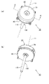
- FIG. 1 is a perspective view of the torque generator according to the first embodiment as viewed from above, and (b) is a perspective view of the torque generator of FIG. 1 (a) as viewed from below.
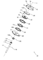
- 1 is an exploded perspective view of the torque generator shown in FIGS. 1A and 1B as viewed from above.
- 1 is an exploded perspective view of the torque generator shown in FIGS. 1A and 1B as viewed from below.
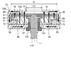
- It is sectional drawing which follows the AA' line of FIG. 1A. It is a cross-sectional view along the line AA'of FIG. 1A, and is a diagram conceptually showing the magnetic field generated by the exciting coil. It is a partially enlarged view of FIG. It is a partially enlarged view of FIG.
- FIGS. 1 to 7 A first embodiment of the torque generator will be described with reference to FIGS. 1 to 7.
- the vertical direction is defined along the central axis 11, but the direction in actual use is not limited.
- the direction along the central axis 11 is referred to as a first direction
- the radial direction orthogonal to the central axis 11 from the central axis 11 is referred to as a second direction.
- the state viewed along the central axis 11 may be referred to as a plan view.
- the display of screws and other members for fixing each member is omitted, and in FIGS. 2 to 5, the display of the ring member 131 and the ferrofluid 140 is omitted.
- the torque generator 10 includes a holding unit 20 and an operating unit 100.
- the operation unit 100 includes a shaft unit 110 and a magnetic disk 120 (see FIGS. 2 and 3) as a first member, and the holding unit 20 is capable of rotating in both directions about a central axis 11 (rotational axis). It is supported.
- the operation unit 100 is supported by the holding unit 20 in a rotatable state via a radial bearing 130 (see FIGS. 2 and 3). Further, as shown in FIGS. 6 and 7, the gap 80 provided in the torque generator 10 is filled with the ferrofluid 140.
- the holding portion 20 includes a first yoke 30 (inner yoke), a second yoke 40 (lower yoke), an exciting coil 50 as a magnetic field generating portion, a bobbin 51, an annular member 60 (O-ring), and an upper case.
- the third yoke 70 (upper yoke) is included.
- the first yoke 30, the second yoke 40, and the third yoke 70 are each separately processed and formed. However, any one of the first yoke 30, the second yoke 40, and the third yoke 70 may be combined and integrally formed.
- the magnetic disk 120 is a first member having an upper surface 120a as a first surface and a lower surface 120b as a second surface.
- the first yoke 30 and the third yoke 70 face the upper surface 120a and the lower surface 120b of the magnetic disk 120, respectively, as the inner surface 72a (third yoke 70) as the first facing surface and the second facing surface.
- It is a second member having an upper surface 30a (first yoke 30).
- the first yoke 30 includes an annular portion 31 and a cylindrical portion 32 integrally provided so as to extend downward concentrically with the annular portion 31.
- the annular portion 31 and the cylindrical portion 32 have a circular shape centered on the central axis 11 in a plan view, and the outer diameter thereof of the cylindrical portion 32 is smaller than that of the annular portion 31. Therefore, the annular portion 31 is an extending portion extending outward from the position of the outer peripheral surface 32a of the cylindrical portion 32 in the radial direction. Due to the difference in outer diameter between the annular portion 31 and the cylindrical portion 32, the step portion 33 is formed on the outer side of the outer peripheral surface 32a of the cylindrical portion 32.
- the first yoke 30 has an inner peripheral surface 34 having a circular shape in a plan view centered on the central axis 11.
- the inner peripheral surface 34 penetrates the annular portion 31 and the cylindrical portion 32 along the central axis 11, and the inner diameter thereof is set so as to change according to the position in the vertical direction.
- an exciting coil 50 as a magnetic field generating portion is arranged on the stepped portion 33 of the first yoke 30 via a bobbin 51.
- the bobbin 51 is an annular member made of a non-magnetic material and having a shape along the lower surface 31a of the annular portion 31 and the outer peripheral surface 32a of the cylindrical portion 32.
- the exciting coil 50 has an annular shape such that the inner peripheral surface 50a is along the outer peripheral surface 51a of the bobbin 51.
- the inner peripheral surface 50a of the exciting coil 50 is located outside the cylindrical portion 32 and inside the outer peripheral surface 31b of the annular portion 31 in the radial direction, and the outer peripheral surface 50b is outside the outer peripheral surface 31b. To position. Therefore, the exciting coil 50 overlaps the annular portion 31 as the extending portion in a plan view.
- the exciting coil 50 is a coil including a conducting wire wound around the central shaft 11.
- a connecting member (not shown) is electrically connected to the exciting coil 50, a current is supplied from the outside, and a magnetic field is generated when the current is supplied to the exciting coil 50.
- annular member 60 is fixed to the annular portion 31 of the first yoke 30 along the outer peripheral surface 31b thereof.
- the annular member 60 has an annular shape and is made of an elastic non-magnetic material such as a synthetic resin.
- the annular member 60 fixed to the first yoke 30 has a circular shape having substantially the same outer diameter as the exciting coil 50 and the bobbin 51 arranged on the stepped portion 33 in a plan view.
- the radial thickness of the annular member 60 prevents the magnetic field generated by the exciting coil 50 from passing radially from the annular portion 31 of the first yoke 30 to the side wall portion 73 of the third yoke 70 through the annular member 60. It is a thickness that can be used.
- the second yoke 40 has a substantially disk shape and is arranged below the first yoke 30.
- the second yoke 40 is provided with a hole 41 that surrounds the central shaft 11 and penetrates in the thickness direction (vertical direction).
- the hole 41 has a circular opening shape having the same center as the third yoke 70 having a substantially circular outer shape when viewed along the thickness direction (vertical direction).
- the shaft portion 110 is inserted into the hole portion 41 via the radial bearing 130.
- the radial bearing 130 is arranged so that the outer peripheral surface 130a is in contact with the hole 41 of the second yoke 40 and the inner peripheral surface 34 of the first yoke 30 communicating with the hole 41.
- the shaft portion 110 is rotatably supported around the central shaft 11 by the action of the radial bearing 130 inside the inner peripheral surface 34 of the first yoke 30 and the hole portion 41 of the second yoke 40.
- the outer shapes of the yokes 30 and 40 do not necessarily have to be circular. Further, the yoke division does not have to be a combination as described above for the first yoke 30 and the second yoke 40, and may have a rectangular outer shape depending on the division position.
- the third yoke 70 includes (1) the first yoke 30, the exciting coil 50, the bobbin 51, and the annular member 60, and (2) the radial bearing 130, the ring member 131, and the shaft. It has a storage space 71 for accommodating the unit 110 and the magnetic disk 120 inside.
- the accommodation space 71 is formed in a circular shape in a plan view by its inner surface portion, that is, the inner surface 72a of the upper wall portion 72 and the inner peripheral surface 73a of the side wall portion 73.
- the accommodation space 71 is formed by the upper wall portion 72 and the side wall portion 73 of the third yoke 70.
- the upper wall portion 72 extends along a radial direction orthogonal to the central axis 11, and its inner surface 72a faces the upper surface 120a (first surface) of the magnetic disk 120 as a first facing surface.
- the upper wall portion 72 has an opening 74 (injection port) penetrating outward from the inner surface 72a in a cylindrical shape centered on the central axis 11 along the thickness direction (direction in which the central axis 11 extends). Is formed.
- the magnetic disk 120 is a disk-shaped member made of a magnetic material, and has an upper surface 120a as a first surface and a lower surface 120b as a second surface, both of which have a central axis. It extends along the radial direction orthogonal to 11 and has a circular shape in a plan view.
- the inner surface 72a of the upper wall portion 72 as the first facing surface has a tapered shape that inclines downward as the distance from the opening 74 increases. Since the upper surface 120a of the magnetic disk 120 as the first surface extends along the radial direction, the gap 80 between the inner surface 72a and the upper surface 120a becomes smaller with a taper angle ⁇ as the distance from the opening 74 increases. ing.
- the opening 74 penetrates the upper wall portion 72 (second member) of the third yoke 70 having the inner surface 72a (first facing surface) in the thickness direction (vertical direction in FIG. 6). ing.
- 1/2 of the opening size of the opening 74 is ⁇ , and the range in which the upper surface 120a (first surface) of the magnetic disk 120 and the inner surface 72a as the first facing surface face each other.
- 1/2 of the length of is L, ⁇ and L are set so as to satisfy the following equation (1).
- the relative movement in the input operation is not limited to the rotation of the magnetic disc 120 accompanying the rotation of the shaft portion 110 around the central axis 11.
- the case where the magnetic disk 120 is moved in the gap 80 in the direction along the central axis 11 or in the direction orthogonal to the central axis 11 may be included.
- the gap 80 becomes smaller with a taper angle ⁇ as the distance from the opening 74 increases in the direction orthogonal to the thickness direction. It is set so as to satisfy the following equation (2).
- d represents the maximum thickness in the thickness direction of the upper wall portion 72 of the third yoke 70, that is, the upper wall portion 72 of the second member facing the upper surface 120a as the first surface.
- the second yoke 40 is fixed to the side wall portion 73 of the third yoke 70 by, for example, a screw (not shown) or by welding. As a result, the outer peripheral portion of the second yoke 40 is fixed in contact with the side wall portion 73 of the third yoke 70, and the second yoke 40 and the third yoke 70 are magnetically connected to each other.
- the first yoke 30 is also fixed to the second yoke 40 by, for example, a screw (not shown) or by welding. As described above, by fixing the first yoke 30, the second yoke 40, and the third yoke 70 to each other, a magnetic path (magnetic circuit) that makes the magnetic field generated by the exciting coil 50 a closed loop can be formed.
- a magnetic path magnetic circuit
- annular member 60 made of a non-magnetic material is fixed to the outer peripheral surface 31b of the annular portion 31 of the first yoke 30, and the outer peripheral surface of the annular member 60 is the side wall portion of the third yoke 70. It is in contact with the inner peripheral surface 73a of 73. Therefore, the annular portion 31 of the first yoke 30 and the side wall portion 73 of the third yoke 70 are separated by the annular member 60 in the direction orthogonal to the central axis 11, and a magnetic gap G (see FIG. 7) is formed. NS. Further, the gap 80 is sealed by the annular member 60, and the magnetic viscous fluid 140 in the gap 80 can be prevented from entering the magnetic gap G, for example, between the first yoke 30 and the third yoke 70.
- the annular member 60 is arranged in the gap 80 so that the lower portion contacts the bobbin 51 made of a non-magnetic material and the upper portion is flush with the upper end of the first yoke 30. Therefore, the magnetic gap G extends in the first direction along the central axis 11 in the order of the gap 80, the annular member 60, and the bobbin 51 from the top, and reaches the upper surface 50c of the exciting coil 50. ..
- the magnetic flux of the magnetic field generated by the exciting coil 50 is transferred from the annular portion 31 of the first yoke 30 to the side wall portion 73 of the third yoke 70, and from the magnetic disk 120 to the third. It is possible to restrict the passage through the side wall portion 73 of the yoke 70 along the direction orthogonal to the central axis 11.
- a magnetic field having a flow in the direction generally indicated by the arrow in FIG. 5 is formed. Further, when a current is applied to the exciting coil 50 in the opposite direction, a magnetic field having a flow opposite to that in FIG. 5 is formed.
- a magnetic flux crosses the magnetic disk 120 from the first yoke 30 to the upper wall portion 72 side of the third yoke 70 along the direction of the central axis 11, and this magnetic flux is applied to the upper wall of the third yoke 70.
- the portion 72 proceeds in a direction away from the central axis 11, and the side wall portion 73 of the third yoke 70 advances from top to bottom along the direction of the central axis 11.
- the magnetic flux traveling from the third yoke 70 to the second yoke 40 travels in the direction approaching the central axis 11 in the second yoke 40, and travels upward to the cylindrical portion 32 of the first yoke 30.
- the process proceeds from bottom to top, that is, toward the ring portion 31 side of the first yoke 30, and again crosses the magnetic disk 120 to reach the third yoke 70. ..
- the magnetic gap G is formed in the magnetic field of such a magnetic path, it is restricted that the magnetic flux passes from the annular portion 31 and the magnetic disk 120 to the side wall portion 73 of the third yoke 70. Further, since the side wall portion 73 of the second yoke 40 and the third yoke 70 is magnetically connected, a magnetic path from the side wall portion 73 to the second yoke 40 is secured.
- the shaft portion 110 as the operation shaft is a rod-shaped member extending vertically along the central shaft 11.
- the shaft portion 110 is provided above the shaft portion 111 provided below the shaft portion 110 and above the shaft portion 111, and is provided above the large diameter portion 112 that is thicker than the shaft portion 111 and above the large diameter portion 112.
- a flange portion 113 that extends in a disk shape in a direction orthogonal to the central axis 11 and a small diameter portion 114 that is provided above the flange portion 113 and is thinner than the large diameter portion 112.
- the magnetic disk 120 is a disk-shaped member having a circular plane arranged so as to be orthogonal to the direction along the central axis 11. As shown in FIG. 4, a central hole 121 penetrating in the vertical direction is provided at the center of the circular plane of the magnetic disk 120. As shown in FIG. 4, in the magnetic disk 120, the small diameter portion 114 of the shaft portion 110 is inserted into the central hole portion 121 from below, and the flange portion 113 is brought into contact with and fixed to the lower surface 120b of the magnetic disk 120. Is fixed to the shaft portion 110. The shaft portion 110 is arranged so that the upper surface 114a of the small diameter portion 114 is flush with the upper surface 120a of the magnetic disk 120.
- the upper portion of the shaft portion 111 and the large diameter portion 112 are rotatably supported by the radial bearing 130, and the upper portion of the large diameter portion 112 is supported from the outside by the ring member 131.
- the ring member 131 is made of an elastic non-magnetic material.
- the radial bearing 130 is supported by the first yoke 30 and the second yoke 40 at predetermined positions in the vertical direction.
- the ring member 131 makes the space between the shaft portion 110 and the first yoke 30 liquid-tight, which prevents the magnetic viscous fluid 140 in the gap 80 from entering the radial bearing 130 side.
- the shaft portion 110 has a central axis with respect to the first yoke 30, the second yoke 40, and the third yoke 70 while maintaining the close contact with the first yoke 30 and the second yoke 40. It is rotatably supported around 11.
- the magnetic disk 120 extends in a direction orthogonal to the central axis 11 in the gap 80 between the first yoke 30 and the third yoke 70, and the first yoke 30.
- the third yoke 70 are arranged so as to be movable relative to the third yoke 70. Therefore, the magnetic disk 120 is positioned so as to overlap with the exciting coil 50 in the direction along the central axis 11. Further, the magnetic disk 120 overlaps the annular portion 31 as an extending portion in a plan view.
- the magnetic disk 120 and the exciting coil 50 may be positioned so that at least a part thereof overlaps with each other in the direction along the central axis 11.
- the gap 80 exists between the upper surface 120a of the magnetic disk 120 and the inner surface 72a of the third yoke 70, and also exists between the lower surface 120b of the magnetic disk 120 and the upper surface 30a of the first yoke 30. Further, the gap 80 exists as a magnetic gap G between the outer peripheral edge of the magnetic disk 120 and the side wall portion 73 of the third yoke 70.
- the magnetic disk 120 rotates relative to the first yoke 30, the second yoke 40, and the third yoke 70 by rotating the shaft portion 110, the upper surface 120a and the third yoke 70 of the magnetic disk 120
- the vertical distance between the magnetic disk 120 and the inner surface 72a is kept substantially constant, and the vertical distance between the lower surface 120b of the magnetic disk 120 and the upper surface 30a of the first yoke 30 is kept substantially constant.
- the radial distance between the outer peripheral edge of the magnetic disk 120 and the side wall portion 73 is also maintained substantially constant.
- the gap 80 around the magnetic disk 120 is filled with the ferrofluid 140. Since the gap 80 around the magnetic disk 120 is sealed by the shaft portion 110, the ring member 131, the first yoke 30, the third yoke 70, the annular member 60, etc., the magnetic viscous fluid 140 is inside the gap 80. Is securely held in.
- the ferrofluid 140 may be present only on either the upper surface 120a side or the lower surface 120b side.
- the magnetic viscous fluid 140 is a substance whose viscosity changes when a magnetic field is applied.
- it is a fluid in which particles (magnetic particles) made of a magnetic material are dispersed in a non-magnetic liquid (solvent).
- the magnetic particles contained in the ferrofluid 140 for example, iron-based particles containing carbon and ferrite particles are preferable.
- the iron-based particles containing carbon for example, the carbon content is preferably 0.15% or more.
- the diameter of the magnetic particles is preferably 0.5 ⁇ m or more, more preferably 1 ⁇ m or more.
- the ferrofluid 140 preferably contains a coupling material that prevents the precipitation of magnetic particles.
- a magnetic field as shown in FIG. 5 is generated as described above, and in the magnetic disk 120, the magnetic flux in the vertical direction crosses and the inside of the magnetic disk 120. Then, the magnetic flux along the radial direction is not generated, or even if it is generated, the magnetic flux density is small. Due to this magnetic field, magnetic field lines are generated along the radial direction in the upper wall portion 72 of the third yoke 70, and in the side wall portion 73 of the third yoke 70, they are along the vertical direction in the direction opposite to the magnetic field lines in the magnetic disk 120. Directional lines of magnetic force are generated. Further, in the second yoke 40, a magnetic field line is generated in a direction opposite to the magnetic field line in the upper wall portion 72 of the third yoke 70 and along the radial direction.
- the magnetic particles are dispersed in the solvent when the magnetic field generated by the exciting coil 50 is not generated. Therefore, when the operator operates the shaft portion 110, the holding portion 20 rotates relative to the operating portion 100 without receiving a large resistance force.
- the exciting coil 50 is not energized and there is residual magnetic flux in the yoke, resistance torque remains in the shaft portion 110 according to the density of the residual magnetic flux.
- the magnetic viscous fluid 140 when a current is applied to the exciting coil 50 to generate a magnetic field, the magnetic viscous fluid 140 is given a magnetic field along the vertical direction. Due to this magnetic field, the magnetic particles dispersed in the magnetic viscous fluid 140 gather along the lines of magnetic force, and the magnetic particles arranged along the vertical direction are magnetically connected to each other to form a cluster. In this state, if a force is applied to rotate the shaft portion 110 in the direction centered on the central axis 11, a shearing force acts on the connected magnetic particles, and a resistance force (torque) is generated by these magnetic particles. .. Therefore, the operator can feel the resistance as compared with the state where the magnetic field is not generated.
- the magnetic viscous fluid 140 can be arranged in a wider range n than in the case of the shaft portion 110 alone. .. Further, the magnitude of the resistance of the ferrofluid 140 is set to a wide range of arrangement of the ferrofluid 140 sandwiched in the vertical direction by the annular portion 31 of the first yoke 30 or 72 of the third yoke 70. Determined based on. In particular, the magnitude of the resistance force of the ferrofluid 140 when the magnetic disk 120 is rotated by operating the shaft portion 110 is related to the area of the ferrofluid 140 on the surface orthogonal to the rotation direction. Therefore, the wider the arrangement range of the ferrofluid 140, the wider the control range of the resistance force (torque) can be.
- the torque generator 10 further includes a control unit (not shown).
- the control unit controls the magnitude of the current applied to the exciting coil 50, thereby controlling the magnitude of the magnetic field generated by the exciting coil 50.
- the control unit includes, for example, a central processing unit and a storage device, and executes control by executing a program stored in the storage device in the central processing unit. By the control by the control unit, the residual magnetic field can be made almost zero, and a stable operation feeling can be given to the operator.
- the residual magnetic field instead of controlling the residual magnetic field to be almost zero, it is possible to control the residual magnetic field to be a substantially constant value. This also makes it possible to give the operator a stable operation feel. In this control, if the residual magnetic flux density is kept above a certain value, the magnetic particles in the ferrofluid 140 are settled by gravity when the current is not applied to the exciting coil 50 for a long time, and the operation is performed. It is possible to prevent the feeling that a person receives from changing.
- the ferrofluid 140 when the ferrofluid 140 is injected into the gap 80 through the opening 74, the vicinity of the opening 74, that is, the opening 74
- the magnetic viscous fluid 140 is smoothly injected into the gap 80 to improve the injection efficiency and is generated. It is possible to minimize the influence of providing the tapered shape on the torque.
- the inner surface 72a of the upper wall portion 72 of the third yoke 70 that is, the first facing surface has a tapered shape, which will be described below.
- a tapered shape may be formed on the upper surface 220a of the magnetic disk 220 as the first surface.
- the third yoke 270 has an upper wall portion 272 having a certain thickness and a side wall having the same configuration as the side wall portion 73 of the first embodiment.
- a portion 273 is provided, and (1) a first yoke 30, an exciting coil 50, a bobbin 51, an annular member 60, and (2) a radial bearing are provided in the accommodation space inside the portion 273, as in the first embodiment.
- the 130, the ring member 131, the shaft portion 110, and the magnetic disk 220 are housed, and the housed space is closed by the second yoke 40.
- the same members as those in the first embodiment are designated by the same reference numerals.
- the upper wall portion 272 is formed with an opening 274 (injection port) penetrating in a cylindrical shape centered on the central axis 11 along the thickness direction thereof.
- the magnetic disk 220 is provided with a central hole portion 221 at the center of a circular plane, and a small diameter portion 114 of the shaft portion 110 is inserted into the central hole portion 221 from below and extends upward.
- the magnetic disk 220 is arranged so that the center of the circular plane of the central hole 221 is located on the central axis 11.
- the upper surface 220a (first surface) of the magnetic disk 220 has a tapered shape that inclines upward as it moves away from the opening 274 or as it moves away from the small diameter portion 114 of the shaft portion 110.
- the inner surface 272a of the third yoke 70 as the first facing surface extends along the radial direction, the gap 280 between the inner surface 272a and the upper surface 220a has a taper angle ⁇ as the distance from the opening 274 increases. It's getting smaller.
- the lower surface 220b of the magnetic disk 220 extends along the radial direction and faces each other in parallel with the upper surface 30a of the first yoke 30.
- the gap 280 becomes smaller with a taper angle ⁇ as the distance from the opening 274 increases in the direction orthogonal to the thickness direction. It is set to satisfy the following equation (2)'. ⁇ ⁇ atan (d / (L- ⁇ )) (2)'
- d is the maximum thickness of the magnetic disk 220 in the thickness direction, that is, the magnetic disk 220 facing the inner surface 272a as the second surface. Note that d does not include the depth h in the direction along the central axis 11 of the opening 274.
- the upper surface 320a of the magnetic disk 320 as the first surface and the top of the third yoke 370 as the first facing surface.
- a tapered shape may be formed on both the inner surface 372a of the wall portion 372.
- the third yoke 370 includes a storage space inside the third yoke 370 (the inner surface 372d of the upper wall portion 372 and the inner peripheral surface (not shown) of the side wall portion 373).
- the first yoke 30, the exciting coil 50, the bobbin 51, and the annular member 60, and (2) the radial bearing 130, the ring member 131, The shaft portion 110 and the magnetic disk 320 are accommodated, and the accommodating space is closed by the second yoke 40.
- the same members as those in the first embodiment are designated by the same reference numerals.
- the upper wall portion 372 is formed with an opening 374 (injection port) penetrating in a cylindrical shape centered on the central axis 11 along the thickness direction thereof.
- the inner surface 372a of the upper wall portion 372 as the first facing surface has a tapered shape that inclines downward as the distance from the opening 374 increases.
- the magnetic disk 320 is provided with a central hole portion 321 at the center of a circular plane, and a small diameter portion 114 of the shaft portion 110 is inserted into the central hole portion 321 from below and extends upward.
- the magnetic disk 320 is arranged so that the center of the circular plane of the central hole portion 321 is located on the central axis 11.
- the upper surface 320a (first surface) of the magnetic disk 320 has a tapered shape that inclines upward as it moves away from the opening 374 or as it moves away from the small diameter portion 114 of the shaft portion 110.
- the inner surface 372a of the third yoke 370 as the first facing surface is inclined downward as it is separated from the opening 374, the inner surface 372a of the upper wall portion 372 and the upper surface 320a of the magnetic disk 320
- the gap 380 between them becomes smaller as the distance from the opening 374 increases.
- the lower surface 320b of the magnetic disk 320 extends along the radial direction and faces each other in parallel with the upper surface 30a of the first yoke 30.
- both the inner surface 372a of the upper wall portion 372 as the first facing surface and the upper surface 320a of the magnetic disk 320 as the first surface are formed in a tapered shape.
- the following equations (3) and (4) are satisfied at the same time.
- the taper angle of the inner surface 372a (first facing surface) of the upper wall portion 372 is ⁇ 1
- the upper wall portion 372 in the direction along the central axis 11, that is, the first surface of the second member The maximum thickness of the upper wall portion 372 facing the upper surface 320a is d1
- the taper angle of the upper surface 320a (first surface) of the magnetic disk 320 is ⁇ 2
- the maximum thickness of the magnetic disk 320 facing the inner surface 372a as the second surface is d2.
- L is 1 ⁇ 2 of the length of the range in which the upper surface 320a (first surface) and the inner surface 372a (first facing surface) face each other. ⁇ 1 ⁇ atan (d1 / (L- ⁇ )) (3) ⁇ 2 ⁇ atan (d2 / (L- ⁇ )) (4)
- the torque generator 310 of the third embodiment when the ferrofluid 140 is injected into the gap 380 through the opening 374, it is applied to both the first surface and the first facing surface which are opposed to each other.
- the magnetic viscous fluid 140 can be smoothly injected into the gap 380 to improve the injection efficiency, and the influence of providing the tapered shape on the generated torque can be suppressed to a small extent. Is possible.
- the present invention has been described with reference to the above-described embodiment, the present invention is not limited to the above-described embodiment, and can be improved or modified within the purpose of improvement or the idea of the present invention.
- the torque generator according to the present invention can efficiently inject the ferrofluid and can generate the torque at the time of relative movement of the first member with a desired magnitude. Useful in terms of points.
- Torque generator 11 Central axis 20 Holding part 30 First yoke 30a Upper surface 31 Circular part 31a Lower surface 31b Outer outer surface 32 Cylindrical part 32a Outer outer surface 33 Step part 34 Inner peripheral surface 40 Second yoke 41 Hole part 50 Excitation coil 50a Peripheral surface 50b Outer peripheral surface 50c Upper surface 51 Bobbing 51a Outer peripheral surface 60 Circular member 70 Third yoke 71 Storage space 72 Upper wall part 72a Inner surface 73 Side wall part 73a Inner peripheral surface 74 Opening 80 Gap 100 Operation part 110 Shaft part 111 Shaft part 112 Large diameter 113 Flange 114 Small diameter 114a Top surface 120 Magnetic disk 120a Top surface 120b Bottom surface 121 Central hole 130 Radial bearing 130a Outer circumference 131 Ring member 140 Magnetic viscous fluid 210 Torque generator 220 Magnetic disk 220a Top surface 220b Bottom surface 221 Central hole 270 Third yoke 272 Upper wall part 272a Inner surface 273 Side wall part 274 Opening part 280 Gap 310
Landscapes
- Engineering & Computer Science (AREA)
- General Engineering & Computer Science (AREA)
- Mechanical Engineering (AREA)
- Physics & Mathematics (AREA)
- Electromagnetism (AREA)
- Braking Arrangements (AREA)
- Fluid-Damping Devices (AREA)
- Electromagnets (AREA)
Abstract
磁気粘性流体の注入効率を高めることができ、かつ、所望のトルクを生成することができるように構成された本発明のトルク発生装置は、入力操作に応じて移動する、第1の面と、この第1の面に対向する第2の面と、を有する第1の部材と、第1の面に対向する第1の対向面と、第2の面に対向する第2の対向面とを含む内面部で形成される収容空間を有し、この収容空間に第1の部材を相対的に移動可能に収容する第2の部材と、収容空間内であって、第1の部材と内面部の間の空間の少なくとも一部に存在させ、磁界に応じて粘性が変化する磁気粘性流体と、磁気粘性流体に作用する磁界を発生させる磁界発生部とを備え、第2の部材には、第1の対向面の一部から外方へ貫通した開口部が設けられ、内面部と第1の面との間に形成される隙間が、開口部から離れるに従って小さくなる。
Description
本発明は、磁気粘性流体を用いて、互いに対向する部材間の相対移動時の抵抗を変化させることができるトルク発生装置に関する。
特許文献1に記載の入力装置は、回転軸を中心に回転動作可能な磁性ディスクを囲むように、複数のヨークを配置し、磁性ディスクと各ヨークとの間に磁気粘性流体を充填している。さらに、磁界を発生するコイルを、回転軸と平行な方向から見て磁性ディスクと重なるように配置するとともに、磁性ディスクにおいて、回転軸に垂直な径方向の外周領域にトルク増大部を設け、磁気粘性流体のクラスタに対するせん断力を、外周領域よりも内側の内周領域に比べて大きくさせている。これにより、小型化に適し、かつ、大きなせん断力を得ることができる入力装置を提供することができるとしている。
しかしながら、特許文献1に記載の入力装置では、磁気粘性流体は支持部材を外した注入口から注入されるところ、磁性ディスク近傍に至るまでの経路が細くかつ複雑であり、さらに、磁性ディスクとこれに対向する第2ヨークとの隙間も薄いため、磁性ディスクと第2ヨークとの隙間へ磁気粘性流体を十分に注入・充填するには長い時間を要し、さらに、磁性ディスクと第1ヨークの隙間まで確実に注入させるのは一層難しく、注入効率を高くすることが困難であった。
これに対して、注入効率を高めるために、注入口近傍の経路を太く単純な構成とすることが考えられるが、この経路は、磁性ディスクとヨークとの隙間とつながっているため、結果として磁性ディスクとヨークとの対向面積が減少したり、対向距離が増大することによって発生するトルクの大きさに影響を与えるおそれがある。さらに、注入口近傍の経路を太くするとともに、磁性ディスクとヨークの隙間に至るまでに徐々に経路を細くする構成も考えられるが、注入効率の向上とトルク生成への影響の抑制のバランスのとれた形状とする必要があり、単純な傾斜形状ではこのようなバランスを取ることは難しい。
本発明は、磁気粘性流体の注入効率の向上とトルク生成への影響の抑制のバランスのとれた具体的な形状に着目したものであって、磁気粘性流体の注入効率を高めることができ、かつ、所望のトルクを生成することができるように構成したトルク発生装置を提供することを目的としている。
上記課題を解決するために、本発明のトルク発生装置は、入力操作に応じて移動する、第1の面と、この第1の面に対向する第2の面と、を有する第1の部材と、第1の面に対向する第1の対向面と、第2の面に対向する第2の対向面とを含む内面部で形成される収容空間を有し、この収容空間に第1の部材を相対的に移動可能に収容する第2の部材と、収容空間内であって、第1の部材と内面部の間の空間の少なくとも一部に存在させ、磁界に応じて粘性が変化する磁気粘性流体と、磁気粘性流体に作用する磁界を発生させる磁界発生部とを備えるトルク発生装置において、第2の部材には、第1の対向面の一部から外方へ貫通した開口部が設けられ、内面部と第1の面との間に形成される隙間が、開口部から離れるに従って小さくなることを特徴としている。
これにより、磁気粘性流体の注入効率を高めることができ、かつ、入力操作の際に所望の抵抗力を生じさせることができるトルク発生装置を提供することが可能となる。
これにより、磁気粘性流体の注入効率を高めることができ、かつ、入力操作の際に所望の抵抗力を生じさせることができるトルク発生装置を提供することが可能となる。
本発明のトルク発生装置において、第1の対向面は、開口部から離れるにしたがって隙間が小さくなるように所定のテーパ形状に形成されていることが好ましい。
本発明のトルク発生装置において、第1の面は、開口部から離れるにしたがって隙間が小さくなるように所定のテーパ形状に形成されていることが好ましい。
本発明のトルク発生装置において、開口部は、第2の部材において第1の対向面を有する壁部を厚み方向に貫通しており、厚み方向に直交する面方向において、開口部の開口サイズの1/2をδ、第1の面と第1の対向面が対向する範囲の長さの1/2をLとし、テーパ形状を形成せずに、第1の対向面と第1の面を互いに平行に形成した場合に、第2の部材に対して第1の部材を相対的に移動させる入力操作において生じるトルクをTaとし、テーパ形状を形成した場合に、トルク発生装置に求められるトルクをTとしたときに、δは次式(1)を満たすことが好ましい。
T<Ta×[(L-δ)3/L3] (1)
T<Ta×[(L-δ)3/L3] (1)
本発明のトルク発生装置において、厚み方向に沿って見たときに、第2の部材は略円形の外形を有し、開口部は、上記外形と中心を同一とする円形の開口形状を有することが好ましい。
本発明のトルク発生装置において、厚み方向に沿った断面において、テーパ形状は、厚み方向に直交する方向に沿って開口部から離れるにしたがってテーパ角θをもって隙間が小さくなっており、厚み方向における第1の面に対向する第2の部材の最大厚みをdとしたとき、テーパ角θは次式(2)を満たすことが好ましい。
θ<atan(d/(L-δ)) (2)
θ<atan(d/(L-δ)) (2)
本発明のトルク発生装置において、第1の対向面及び第1の面の両方にテーパ形状に形成されている場合、第1の対向面についてのテーパ角をθ1、第1の面に対向する第2の部材の最大厚みをd1とし、第1の面についてのテーパ角をθ2と、第2の面に対向する第1の部材の最大厚みをd2’としたとき、次式(3)、(4)を同時に満たすことが好ましい。
θ1<atan(d1/(L-δ)) (3)
θ2<atan(d2/(L-δ)) (4)
θ1<atan(d1/(L-δ)) (3)
θ2<atan(d2/(L-δ)) (4)
本発明によると、磁気粘性流体の注入効率を高めることができ、かつ、所望のトルクを生成することができるように構成したトルク発生装置を提供することができる。
以下、本発明の実施形態に係るトルク発生装置について図面を参照しつつ詳しく説明する。
<第1実施形態>
図1~図7を参照しつつ、トルク発生装置の第1実施形態について説明する。
各図において、説明の便宜上、中心軸11に沿って上下方向を規定しているが、実際の使用時における方向を制限するものではない。以下、中心軸11に沿った方向を第1の方向とし、中心軸11から、中心軸11に直交する径方向を第2の方向と称する。また、中心軸11に沿って見た状態を平面視ということがある。また、各図においては、各部材を固定するためのネジその他の部材の表示を省略し、図2~図5においてはリング部材131と磁気粘性流体140の表示を省略している。
<第1実施形態>
図1~図7を参照しつつ、トルク発生装置の第1実施形態について説明する。
各図において、説明の便宜上、中心軸11に沿って上下方向を規定しているが、実際の使用時における方向を制限するものではない。以下、中心軸11に沿った方向を第1の方向とし、中心軸11から、中心軸11に直交する径方向を第2の方向と称する。また、中心軸11に沿って見た状態を平面視ということがある。また、各図においては、各部材を固定するためのネジその他の部材の表示を省略し、図2~図5においてはリング部材131と磁気粘性流体140の表示を省略している。
図1(a)、(b)に示すように、トルク発生装置10は、保持部20と、操作部100とを備える。操作部100は、シャフト部110と、第1部材としての磁性ディスク120(図2・図3参照)とを含み、中心軸11(回転軸)を中心として両方向に回転動作可能に保持部20に支持されている。操作部100は、ラジアル軸受130を介して、回転可能な状態で保持部20に支持されている(図2・図3参照)。さらに、図6と図7に示すように、トルク発生装置10内に設けた隙間80には、磁気粘性流体140が満たされている。
保持部20は、第1ヨーク30(内側ヨーク)、第2ヨーク40(下側ヨーク)、磁界発生部としての励磁コイル50、ボビン51、環状部材60(Oリング)、及び、上部ケースとしての第3ヨーク70(上側ヨーク)を含む。第1ヨーク30、第2ヨーク40、第3ヨーク70は、それぞれ別々に加工されて形成されている。ただし、第1ヨーク30、第2ヨーク40、第3ヨーク70のいずれかが組み合わされて一体に形成されていてもよい。
ここで、磁性ディスク120は、第1の面としての上面120aと、第2の面としての下面120bとを備えた第1の部材である。一方、第1ヨーク30と第3ヨーク70は、磁性ディスク120の上面120aと下面120bにそれぞれ対向する、第1の対向面としての内面72a(第3ヨーク70)と第2の対向面としての上面30a(第1ヨーク30)を備えた第2の部材である。
図4に示すように、第1ヨーク30は、円環部31と、円環部31と同心状に下側へ延びるように一体に設けられた円筒部32とを備える。円環部31と円筒部32は、平面視において、中心軸11を中心とする円形状をなしており、その外径は、円環部31よりも円筒部32の方が小さくされている。したがって、円環部31は、径方向において円筒部32の外周面32aの位置から外側へ延在する延在部となっている。円環部31と円筒部32の外径の違いにより、円筒部32の外周面32aの外側に段差部33が形成される。また、第1ヨーク30は、中心軸11を中心とした平面視円形状の内周面34を有する。内周面34は、中心軸11に沿って円環部31と円筒部32を貫いており、その内径は、上下方向の位置に応じて変化するように設定されている。
図4に示すように、第1ヨーク30の段差部33には、ボビン51を介して、磁界発生部としての励磁コイル50が配設される。ボビン51は、非磁性材料からなり、円環部31の下面31a及び円筒部32の外周面32aに沿った形状を有する環状部材である。
励磁コイル50は、内周面50aがボビン51の外周面51aに沿うような円環状をなしている。励磁コイル50の内周面50aは、径方向において、円筒部32よりも外側であって円環部31の外周面31bよりも内側に位置し、外周面50bは前記外周面31bよりも外側に位置する。よって、励磁コイル50は、平面視において、延在部としての円環部31に重なっている。励磁コイル50は、中心軸11の周りを回るように巻き付けられた導線を含むコイルである。励磁コイル50には不図示の接続部材が電気的に接続され、外部から電流が供給され、励磁コイル50に電流が供給されると磁界が発生する。
図4に示すように、第1ヨーク30の円環部31には、その外周面31bに沿って環状部材60が固定されている。この環状部材60は円環状をなしており、合成樹脂などの弾性を有する非磁性材料で構成される。第1ヨーク30に固定された状態の環状部材60は、平面視において、段差部33に配設された励磁コイル50及びボビン51と略同一の外径の円形状を有する。環状部材60の径方向の厚みは、励磁コイル50が発生した磁界が、環状部材60を通じて第1ヨーク30の円環部31から第3ヨーク70の側壁部73へ、径方向に通じることを妨げることができる厚みとなっている。
図4に示すように、第2ヨーク40は、略円板状をなしており、第1ヨーク30の下方に配設される。第2ヨーク40は、中心軸11を囲んで、厚み方向(上下方向)に貫通する孔部41が設けられている。孔部41は、厚み方向(上下方向)に沿って見たときに、略円形の外形を有する第3ヨーク70に対して中心を同一とする円形の開口形状を有する。孔部41内には、ラジアル軸受130を介してシャフト部110が挿入される。
ラジアル軸受130は、第2ヨーク40の孔部41と、孔部41に連通する、第1ヨーク30の内周面34とに外周面130aが接するように配置される。これにより、シャフト部110は、第1ヨーク30の内周面34及び第2ヨーク40の孔部41の内側において、ラジアル軸受130の作用によって中心軸11を中心として回転自在に支持される。
なお、ヨーク30、40の外形は必ずしも円形でなくてもよい。また、ヨークの分割は、上述の第1ヨーク30と第2ヨーク40のような組み合わせでなくても良く、分割位置によっては矩形状の外形とすることもできる。
図3又は図4に示すように、第3ヨーク70は、(1)第1ヨーク30、励磁コイル50、ボビン51、及び、環状部材60と、(2)ラジアル軸受130、リング部材131、シャフト部110、及び、磁性ディスク120とを内部に収容する収容空間71を有する。この収容空間71は、その内面部、すなわち、上壁部72の内面72aと、側壁部73の内周面73aとによって平面視円形状に形成されている。
図4に示すように、収容空間71は、第3ヨーク70の上壁部72と側壁部73によって形成されている。上壁部72は、中心軸11に直交する径方向に沿って延び、その内面72aは、第1の対向面として、磁性ディスク120の上面120a(第1の面)に対向する。上壁部72には、その厚み方向(中心軸11の延びる方向)に沿って、中心軸11を中心とした円筒状に、内面72aから外方へ向けて貫通した開口部74(注入口)が形成されている。
ここで、磁性ディスク120は、磁性材料で構成された円板状の部材であって、第1の面としての上面120aと、第2の面としての下面120bとを有し、いずれも中心軸11に直交する径方向に沿って延び、平面視円形状をなしている。
図6に示すように、第1の対向面としての、上壁部72の内面72aは、開口部74から離れるに従って、下側へ傾斜していくテーパ形状を有する。第1の面としての、磁性ディスク120の上面120aは、径方向に沿って延びているため、内面72aと上面120aとの間の隙間80は、開口部74から離れるに従ってテーパ角θをもって小さくなっている。
上壁部72の内面72aのテーパ形状について、図6を参照しつつ説明する。
上述のように、開口部74は、内面72a(第1の対向面)を有する、第3ヨーク70の上壁部72(第2の部材)を厚み方向(図6の上下方向)に貫通している。厚み方向に直交する面方向において、開口部74の開口サイズの1/2をδ、磁性ディスク120の上面120a(第1の面)と第1の対向面としての内面72aとが互いに対向する範囲の長さの1/2をLとしたとき、次式(1)を満たすようにδとLを設定している。
T<Ta×[(L-δ)3/L3] (1)
ここで、トルクTaは、内面72aをテーパ形状として形成せずに、磁性ディスク120の上面120a(第1の面)に対して平行に形成した場合に、上壁部72(第2の部材)に対して磁性ディスク120(第1の部材)を相対的に移動させる入力操作において生じるトルクである。また、トルクTは、内面72aにテーパ形状を形成した場合に、トルク発生装置に求められるトルクである。
上述のように、開口部74は、内面72a(第1の対向面)を有する、第3ヨーク70の上壁部72(第2の部材)を厚み方向(図6の上下方向)に貫通している。厚み方向に直交する面方向において、開口部74の開口サイズの1/2をδ、磁性ディスク120の上面120a(第1の面)と第1の対向面としての内面72aとが互いに対向する範囲の長さの1/2をLとしたとき、次式(1)を満たすようにδとLを設定している。
T<Ta×[(L-δ)3/L3] (1)
ここで、トルクTaは、内面72aをテーパ形状として形成せずに、磁性ディスク120の上面120a(第1の面)に対して平行に形成した場合に、上壁部72(第2の部材)に対して磁性ディスク120(第1の部材)を相対的に移動させる入力操作において生じるトルクである。また、トルクTは、内面72aにテーパ形状を形成した場合に、トルク発生装置に求められるトルクである。
ここで、入力操作における相対的な移動には、シャフト部110を中心軸11を中心に回転させることにともなう磁性ディスク120の回転だけに限定されない。例えば、隙間80内において、磁性ディスク120を、中心軸11に沿った方向に、又は、中心軸11に直交する方向に移動させた場合も含みうる。
さらに、内面72aのテーパ形状は、図6に示す、厚み方向に沿った断面において、厚み方向に直交する方向に沿って開口部74から離れるにしたがってテーパ角θをもって隙間80が小さくなっており、次式(2)を満たすように設定される。
θ<atan(d/(L-δ)) (2)
ここで、dは第3ヨーク70の上壁部72、すなわち、第2の部材のうち、第1の面としての上面120aに対向する上壁部72、の厚み方向における最大厚みを表すものである。このように、開口部74から磁気粘性流体140を注入するにあたり、その注入効率を向上させるために、隙間80に対してテーパ形状を形成した際にも、(1)式及び(2)式に基づき、トルク発生装置に求められるトルクに基づいてδ、L、θを設定することで、所望のトルクを発生できるように調整できるものである。つまり、テーパ形状を形成する際に発生するトルクへの影響を小さく抑えることができる。
θ<atan(d/(L-δ)) (2)
ここで、dは第3ヨーク70の上壁部72、すなわち、第2の部材のうち、第1の面としての上面120aに対向する上壁部72、の厚み方向における最大厚みを表すものである。このように、開口部74から磁気粘性流体140を注入するにあたり、その注入効率を向上させるために、隙間80に対してテーパ形状を形成した際にも、(1)式及び(2)式に基づき、トルク発生装置に求められるトルクに基づいてδ、L、θを設定することで、所望のトルクを発生できるように調整できるものである。つまり、テーパ形状を形成する際に発生するトルクへの影響を小さく抑えることができる。
第2ヨーク40は、第3ヨーク70の側壁部73に対して、例えば、ネジ(不図示)により、又は溶接によって固定される。これによって、第2ヨーク40の外周部が第3ヨーク70の側壁部73に接触した状態で固定され、第2ヨーク40と第3ヨーク70とが互いに磁気的に接続される。
第1ヨーク30についても、第2ヨーク40に対して、例えば、ネジ(不図示)により、又は溶接によって固定される。以上のように、第1ヨーク30、第2ヨーク40、及び、第3ヨーク70を互いに固定することにより、励磁コイル50が発生する磁界を閉ループにする磁路(磁気回路)が形成できる。
上述のように、第1ヨーク30の円環部31の外周面31bには、非磁性材料からなる環状部材60が固定されており、この環状部材60の外周面が第3ヨーク70の側壁部73の内周面73aに接している。したがって、第1ヨーク30の円環部31と第3ヨーク70の側壁部73とは、中心軸11に直交する方向において環状部材60によって離間されており磁気ギャップG(図7参照)が形成される。また、隙間80が環状部材60によって封止され、隙間80内の磁気粘性流体140が磁気ギャップG内、例えば、第1ヨーク30と第3ヨーク70の間に侵入することを防ぐことができる。
図7に示すように、環状部材60は、下部が非磁性材料のボビン51に接触し、上部は、第1ヨーク30の上端と同一面となるように、隙間80内に配置されている。したがって、磁気ギャップGは、中心軸11に沿った第1の方向において、上から、隙間80、環状部材60、ボビン51の順に互い隣り合って延在し、励磁コイル50の上面50cに至っている。
このような磁気ギャップGを設けることによって、励磁コイル50が発生した磁界の磁束が、第1ヨーク30の円環部31から第3ヨーク70の側壁部73へ、また、磁性ディスク120から第3ヨーク70の側壁部73へ、中心軸11に直交する方向に沿って通過することを規制することができる。
以上の構成において、励磁コイル50に電流を印加すると図5の矢印で概略的に示す方向の流れを有する磁界が形成される。また、励磁コイル50に対して逆向きに電流を印加すると、図5とは逆向きの流れの磁界が形成される。図5に示す例では、中心軸11の方向に沿って第1ヨーク30から第3ヨーク70の上壁部72側へ磁束が磁性ディスク120を横断し、この磁束は第3ヨーク70の上壁部72では中心軸11から遠ざかる方向へ進み、第3ヨーク70の側壁部73では中心軸11の方向に沿って上から下へ進む。
さらに、第3ヨーク70から第2ヨーク40へ進んだ磁束は、第2ヨーク40では中心軸11へ近づく方向へ進み、第1ヨーク30の円筒部32へ上向きに進行する。円筒部32内では、励磁コイル50の内側に対応する領域で、下から上へ、すなわち第1ヨーク30の円環部31側へ進み、再び磁性ディスク120を横断して第3ヨーク70に至る。
このような磁路の磁界において、磁気ギャップGが形成されているために、円環部31及び磁性ディスク120から第3ヨーク70の側壁部73に磁束が通過することは規制されている。また、第2ヨーク40と第3ヨーク70の側壁部73が磁気的に接続されているため、側壁部73から第2ヨーク40を通る磁路が確保される。
次に、操作部100の構造について説明する。
図2・図3に示すように、操作軸としてのシャフト部110は、中心軸11に沿って上下に延びる棒状材である。シャフト部110は、シャフト部110の下側に設けられた軸部111と、軸部111の上部に設けられ、軸部111よりも太い大径部112と、大径部112の上部に設けられ、中心軸11に直交する方向に円板状に広がるフランジ部113と、フランジ部113の上部に設けられ、大径部112よりも細い小径部114とを備える。
図2・図3に示すように、操作軸としてのシャフト部110は、中心軸11に沿って上下に延びる棒状材である。シャフト部110は、シャフト部110の下側に設けられた軸部111と、軸部111の上部に設けられ、軸部111よりも太い大径部112と、大径部112の上部に設けられ、中心軸11に直交する方向に円板状に広がるフランジ部113と、フランジ部113の上部に設けられ、大径部112よりも細い小径部114とを備える。
図2・図3に示すように、磁性ディスク120は、中心軸11に沿った方向に直交するように配置される円形平面を有する円板状の部材である。図4に示すように、磁性ディスク120の円形平面の中心には、上下方向に貫通する中央孔部121が設けられている。図4に示すように、磁性ディスク120は、下方から中央孔部121内に、シャフト部110の小径部114を挿通させ、かつ、フランジ部113を磁性ディスク120の下面120bに接触・固定することによって、シャフト部110に対して固定される。シャフト部110は、小径部114の上面114aが磁性ディスク120の上面120aと同一面をなすように配置される。
図4に示すように、シャフト部110は、軸部111の上部、及び、大径部112がラジアル軸受130によって回転自在に支持され、大径部112の上部がリング部材131によって外側から支持されている。リング部材131は、弾性を有する非磁性材料で構成される。ラジアル軸受130は、第1ヨーク30及び第2ヨーク40によって、上下方向の所定位置で支持される。リング部材131により、シャフト部110と第1ヨーク30との間が液密となり、これにより、隙間80内の磁気粘性流体140がラジアル軸受130側に侵入することを防ぐことができる。以上の構成により、シャフト部110は、第1ヨーク30及び第2ヨーク40との密着性を維持しつつ、第1ヨーク30、第2ヨーク40、及び、第3ヨーク70に対して、中心軸11を中心として回転可能に支持される。
図4~図6に示すように、磁性ディスク120は、第1ヨーク30と第3ヨーク70との間の隙間80において、中心軸11に直交する方向に延びるように、且つ、第1ヨーク30と第3ヨーク70に対して相対的に移動可能に配設されている。よって、磁性ディスク120は、中心軸11に沿った方向において、励磁コイル50と互いに重複するように位置する。また、磁性ディスク120は、平面視において、延在部としての円環部31に重なる。ここで、磁性ディスク120と励磁コイル50は、中心軸11に沿った方向において、少なくとも一部が重複するように位置していればよい。隙間80は、磁性ディスク120の上面120aと第3ヨーク70の内面72aとの間に存在し、また、磁性ディスク120の下面120bと第1ヨーク30の上面30aとの間に存在する。さらに、隙間80は、磁性ディスク120の外周縁と第3ヨーク70の側壁部73との間において、磁気ギャップGとして存在している。
シャフト部110を回転操作することによって磁性ディスク120が、第1ヨーク30、第2ヨーク40、及び第3ヨーク70に対して相対的に回転するとき、磁性ディスク120の上面120aと第3ヨーク70の内面72aとの間の上下方向の距離は、略一定に保たれ、磁性ディスク120の下面120bと第1ヨーク30の上面30aとの間の上下方向の距離は略一定に保たれ、さらに、磁性ディスク120の外周縁と側壁部73との径方向の距離も略一定に維持される。
図5・図6に示すように、磁性ディスク120の周囲の隙間80には磁気粘性流体140が満たされている。磁性ディスク120の周囲の隙間80は、シャフト部110、リング部材131、第1ヨーク30、第3ヨーク70、及び、環状部材60等で封止されているため、磁気粘性流体140は隙間80内に確実に保持される。
ここで、隙間80の全てが磁気粘性流体140で埋められていなくてもよい。例えば、磁気粘性流体140は、上面120a側と下面120b側とのいずれか一方のみに存在していてもよい。
磁気粘性流体140は、磁界が印加されると粘性が変化する物質であり、例えば、非磁性の液体(溶媒)中に磁性材料からなる粒子(磁性粒子)が分散された流体である。磁気粘性流体140に含まれる磁性粒子としては、例えば、カーボンを含有した鉄系の粒子やフェライト粒子が好ましい。カーボンを含有した鉄系の粒子としては、例えば、カーボン含有量が0.15%以上であることが好ましい。磁性粒子の直径は、例えば0.5μm以上が好ましく、さらには1μm以上が好ましい。磁気粘性流体140は、磁性粒子が重力で沈殿しにくくなるように、溶媒と磁性粒子を選定することが望ましい。さらに、磁気粘性流体140は、磁性粒子の沈殿を防ぐカップリング材を含むことが望ましい。
励磁コイル50に対して電流が印加されると、上述したように図5に示すような磁界が発生し、磁性ディスク120においては上下方向に沿った方向の磁束が横断し、磁性ディスク120の内部では、径方向に沿った磁束は生じないか生じてもその磁束密度はわずかである。この磁界により、第3ヨーク70の上壁部72においては径方向に沿った磁力線が生じ、第3ヨーク70の側壁部73においては、磁性ディスク120における磁力線とは逆方向で上下方向に沿った方向の磁力線が生じる。さらに、第2ヨーク40においては、第3ヨーク70の上壁部72における磁力線とは逆方向であって径方向に沿った方向の磁力線が生じる。
磁気粘性流体140においては、励磁コイル50による磁界が生じていないときには、磁性粒子は溶媒内で分散されている。したがって、操作者がシャフト部110を操作すると、保持部20は、大きな抵抗力を受けずに、操作部100に対して相対的に回転する。あるいは、励磁コイル50に通電されていない状態で、ヨーク内に残留磁束があるときは、その残留磁束の密度に応じてシャフト部110に抵抗トルクが残留する。
一方、励磁コイル50に電流を印加して磁界を発生させると、磁気粘性流体140には上下方向に沿った磁界が与えられる。この磁界により、磁気粘性流体140中で分散していた磁性粒子は磁力線に沿って集まり、上下方向に沿って並んだ磁性粒子が磁気的に互いに連結され、クラスタが形成される。この状態において、中心軸11を中心とする方向にシャフト部110を回転させようとする力を与えると、連結された磁性粒子にせん断力がはたらき、これらの磁性粒子による抵抗力(トルク)が生じる。このため、磁界を発生させていない状態と比べて操作者に抵抗力を感じさせることができる。
以上述べたように、シャフト部110から径方向外側に円板状に広がった磁性ディスク120を使用しているため、シャフト部110だけの場合に比べると広い範囲nに磁気粘性流体140を配置できる。さらに、磁気粘性流体140の抵抗力の大きさは、第1ヨーク30の円環部31、又は、第3ヨーク70の72に上下方向を挟まれた磁気粘性流体140の配置範囲の広さに基づいて定まる。特に、シャフト部110の操作によって磁性ディスク120を回転させたときの磁気粘性流体140による抵抗力の大きさは、その回転方向に直交する面の磁気粘性流体140の面積に関係する。よって、磁気粘性流体140の配置範囲が広くなるほど、抵抗力(トルク)の制御幅を広くすることができる。
トルク発生装置10は、不図示の制御部をさらに備える。制御部は、励磁コイル50に印加する電流の大きさを制御し、これによって励磁コイル50が発生する磁界の大きさを制御する。制御部は、例えば、中央演算処理装置と記憶装置とを含み、記憶装置に記憶されたプログラムを中央演算処理装置で実行することにより制御を実行する。制御部による制御によって、残留磁場をほぼゼロとすることができ、操作者に対して安定した操作感触を与えることができる。
また、残留磁場をほぼゼロとする制御に代えて、残留磁場が略一定値となるように制御することもできる。これによっても、操作者に対して安定した操作感触を与えることが可能となる。この制御においては、残留磁束密度を一定値以上に保つようにすると、励磁コイル50への電流の印加を長い時間にわたって行わなかったときに重力によって磁気粘性流体140中の磁性粒子が沈殿し、操作者が受ける感触が変化してしまうことを防ぐことができる。
以上のように構成されたことから、上記第1実施形態によれば、開口部74を介して磁気粘性流体140を隙間80内へ注入する際に、開口部74の近傍、すなわち、開口部74に連設された、第1対向面としての内面72aに所定のテーパ形状を形成することにより、隙間80への磁気粘性流体140の注入をスムーズに行って注入効率を高め、かつ、生成されるトルクに対してテーパ形状を設けることの影響を小さく抑えることが可能となる。
<第2実施形態>
上記第1実施形態においては、隙間80を形成する面のうち、第3ヨーク70の上壁部72の内面72a、すなわち第1対向面にテーパ形状を形成していたが、以下に説明する第2実施形態のように、第1の面としての、磁性ディスク220の上面220aにテーパ形状を形成してもよい。
上記第1実施形態においては、隙間80を形成する面のうち、第3ヨーク70の上壁部72の内面72a、すなわち第1対向面にテーパ形状を形成していたが、以下に説明する第2実施形態のように、第1の面としての、磁性ディスク220の上面220aにテーパ形状を形成してもよい。
図8・図9に示す第2実施形態のトルク発生装置210において、第3ヨーク270は、一定の厚さを有する上壁部272と、第1実施形態の側壁部73と同様の構成の側壁部273とを有し、その内側の収容空間内に、第1実施形態と同様に、(1)第1ヨーク30、励磁コイル50、ボビン51、及び、環状部材60と、(2)ラジアル軸受130、リング部材131、シャフト部110、及び、磁性ディスク220とを収容し、第2ヨーク40によって収容空間が閉じられる。
なお、図8・図9において、第1実施形態と同様の部材については同じ符号を付している。
なお、図8・図9において、第1実施形態と同様の部材については同じ符号を付している。
上壁部272には、その厚み方向に沿って、中心軸11を中心とした円筒状に貫通した開口部274(注入口)が形成されている。
磁性ディスク220は、円形平面の中心に中央孔部221が設けられ、この中央孔部221にシャフト部110の小径部114が下から挿入され、上側へ延出している。磁性ディスク220は、中央孔部221の円形平面の中心が中心軸11上に位置するように配置される。
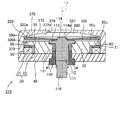
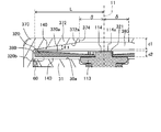
図9に示すように、磁性ディスク220の上面220a(第1の面)は、開口部274から離れるに従って、又は、シャフト部110の小径部114から離れるに従って、上側へ傾斜していくテーパ形状を有する。第1の対向面としての、第3ヨーク70の内面272aは、径方向に沿って延びているため、内面272aと上面220aとの間の隙間280は、開口部274から離れるに従ってテーパ角θをもって小さくなっている。
なお、磁性ディスク220の下面220bは、径方向に沿って延びており、第1ヨーク30の上面30aと平行に互いに対向している。
なお、磁性ディスク220の下面220bは、径方向に沿って延びており、第1ヨーク30の上面30aと平行に互いに対向している。
厚み方向に直交する面方向において、開口部274の開口サイズの1/2をδ、磁性ディスク220の上面220a(第1の面)が第1の対向面としての、上壁部272の内面272aと対向する範囲の長さの1/2をLとしたとき、次式(1)’を満たすようにδとLを設定している。
T<Ta×[(L-δ)3/L3] (1)’
ここで、トルクTaは、上面220aをテーパ形状として形成せずに、第3ヨーク270の内面272a(第1の対向面)に対して平行に形成した場合に、上壁部272(第2の部材)に対して磁性ディスク220(第1の部材)を相対的に移動させる入力操作において生じるトルクである。また、トルクTは、磁性ディスク220の上面220aにテーパ形状を形成した場合に、トルク発生装置に求められるトルクである。
T<Ta×[(L-δ)3/L3] (1)’
ここで、トルクTaは、上面220aをテーパ形状として形成せずに、第3ヨーク270の内面272a(第1の対向面)に対して平行に形成した場合に、上壁部272(第2の部材)に対して磁性ディスク220(第1の部材)を相対的に移動させる入力操作において生じるトルクである。また、トルクTは、磁性ディスク220の上面220aにテーパ形状を形成した場合に、トルク発生装置に求められるトルクである。
さらに、上面220aのテーパ形状は、図7に示す、厚み方向に沿った断面において、厚み方向に直交する方向に沿って開口部274から離れるにしたがってテーパ角θをもって隙間280が小さくなっており、次式(2)’を満たすように設定される。
θ<atan(d/(L-δ)) (2)’
ここで、dは厚み方向における磁性ディスク220、すなわち、第2の面としての内面272aに対向する磁性ディスク220、の最大厚さである。なお、dには、開口部274の中心軸11に沿った方向における深さhは含まれない。
θ<atan(d/(L-δ)) (2)’
ここで、dは厚み方向における磁性ディスク220、すなわち、第2の面としての内面272aに対向する磁性ディスク220、の最大厚さである。なお、dには、開口部274の中心軸11に沿った方向における深さhは含まれない。
このような構成により、開口部274を介して磁気粘性流体140を隙間280内へ注入する際に、第1の面としての、磁性ディスク220の上面220aに所定のテーパ形状を形成することにより、隙間280への磁気粘性流体140の注入をスムーズに行って注入効率を高め、かつ、生成されるトルクに対してテーパ形状を設けることの影響を小さく抑えることが可能となる。
<第3実施形態>
第1実施形態及び第2実施形態に対して、第3実施形態のように、第1の面としての、磁性ディスク320の上面320aと、第1の対向面としての、第3ヨーク370の上壁部372の内面372aとの両方にテーパ形状を形成してもよい。
第1実施形態及び第2実施形態に対して、第3実施形態のように、第1の面としての、磁性ディスク320の上面320aと、第1の対向面としての、第3ヨーク370の上壁部372の内面372aとの両方にテーパ形状を形成してもよい。
図10・図11に示す第3実施形態のトルク発生装置310において、第3ヨーク370は、その内側の収容空間(上壁部372の内面372dと側壁部373の内周面(不図示)とによって形成される空間)内に、第1実施形態と同様に、(1)第1ヨーク30、励磁コイル50、ボビン51、及び、環状部材60と、(2)ラジアル軸受130、リング部材131、シャフト部110、及び、磁性ディスク320とを収容し、第2ヨーク40によって収容空間が閉じられる。
なお、図10・図11において、第1実施形態と同様の部材については同じ符号を付している。
なお、図10・図11において、第1実施形態と同様の部材については同じ符号を付している。
上壁部372には、その厚み方向に沿って、中心軸11を中心とした円筒状に貫通した開口部374(注入口)が形成されている。第1の対向面としての、上壁部372の内面372aは、開口部374から離れるに従って、下側へ傾斜していくテーパ形状を有する。
磁性ディスク320は、円形平面の中心に中央孔部321が設けられ、この中央孔部321にシャフト部110の小径部114が下から挿入され、上側へ延出している。磁性ディスク320は、中央孔部321の円形平面の中心が中心軸11上に位置するように配置される。
図11に示すように、磁性ディスク320の上面320a(第1の面)は、開口部374から離れるに従って、又は、シャフト部110の小径部114から離れるに従って、上側へ傾斜していくテーパ形状を有する。第1の対向面としての、第3ヨーク370の内面372aは、開口部374から離れるに従って、下側へ傾斜しているため、上壁部372の内面372aと、磁性ディスク320の上面320aとの間の隙間380は、開口部374から離れるに従って小さくなっている。
なお、磁性ディスク320の下面320bは、径方向に沿って延びており、第1ヨーク30の上面30aと平行に互いに対向している。
なお、磁性ディスク320の下面320bは、径方向に沿って延びており、第1ヨーク30の上面30aと平行に互いに対向している。
第3実施形態のトルク発生装置310においては、第1の対向面としての、上壁部372の内面372aと、第1の面としての、磁性ディスク320の上面320aとの両方にテーパ形状に形成されており、次の式(3)、(4)が同時に満たされる。ここで、上壁部372の内面372a(第1の対向面)についてのテーパ角をθ1、中心軸11に沿った方向における上壁部372、すなわち、第2の部材のうち、第1の面としての上面320aに対向する上壁部372、の最大厚みをd1とし、磁性ディスク320の上面320a(第1の面)についてのテーパ角をθ2と、中心軸11に沿った方向における磁性ディスク320、すなわち、第2の面としての内面372aに対向する磁性ディスク320の、最大厚みをd2としている。また、径方向において、上面320a(第1の面)と内面372a(第1の対向面)が互いに対向する範囲の長さの1/2をLとしている。
θ1<atan(d1/(L-δ)) (3)
θ2<atan(d2/(L-δ)) (4)
θ1<atan(d1/(L-δ)) (3)
θ2<atan(d2/(L-δ)) (4)
第3実施形態のトルク発生装置310によれば、開口部374を介して磁気粘性流体140を隙間380内へ注入する際に、互いに対向する、第1の面と第1の対向面の両方に所定のテーパ形状を形成することにより、隙間380への磁気粘性流体140の注入をスムーズに行って注入効率を高め、かつ、生成されるトルクに対してテーパ形状を設けることの影響を小さく抑えることが可能となる。
本発明について上記実施形態を参照しつつ説明したが、本発明は上記実施形態に限定されるものではなく、改良の目的または本発明の思想の範囲内において改良または変更が可能である。
本発明について上記実施形態を参照しつつ説明したが、本発明は上記実施形態に限定されるものではなく、改良の目的または本発明の思想の範囲内において改良または変更が可能である。
以上のように、本発明に係るトルク発生装置は、磁気粘性流体を効率良く注入することができ、かつ、第1の部材の相対移動の際のトルクを所望の大きさで生成することができる点で有用である。
10 トルク発生装置
11 中心軸
20 保持部
30 第1ヨーク
30a 上面
31 円環部
31a 下面
31b 外周面
32 円筒部
32a 外周面
33 段差部
34 内周面
40 第2ヨーク
41 孔部
50 励磁コイル
50a 内周面
50b 外周面
50c 上面
51 ボビン
51a 外周面
60 環状部材
70 第3ヨーク
71 収容空間
72 上壁部
72a 内面
73 側壁部
73a 内周面
74 開口部
80 隙間
100 操作部
110 シャフト部
111 軸部
112 大径部
113 フランジ部
114 小径部
114a 上面
120 磁性ディスク
120a 上面
120b 下面
121 中央孔部
130 ラジアル軸受
130a 外周面
131 リング部材
140 磁気粘性流体
210 トルク発生装置
220 磁性ディスク
220a 上面
220b 下面
221 中央孔部
270 第3ヨーク
272 上壁部
272a 内面
273 側壁部
274 開口部
280 隙間
310 トルク発生装置
320 磁性ディスク
320a 上面
320b 下面
321 中央孔部
370 第3ヨーク
372 上壁部
372a 内面
373 側壁部
374 開口部
380 隙間
G 磁気ギャップ
L 第1の面と第1の対向面が対向する範囲の長さの1/2
δ 開口サイズの1/2
h 深さ
d、d1、d2 厚み
11 中心軸
20 保持部
30 第1ヨーク
30a 上面
31 円環部
31a 下面
31b 外周面
32 円筒部
32a 外周面
33 段差部
34 内周面
40 第2ヨーク
41 孔部
50 励磁コイル
50a 内周面
50b 外周面
50c 上面
51 ボビン
51a 外周面
60 環状部材
70 第3ヨーク
71 収容空間
72 上壁部
72a 内面
73 側壁部
73a 内周面
74 開口部
80 隙間
100 操作部
110 シャフト部
111 軸部
112 大径部
113 フランジ部
114 小径部
114a 上面
120 磁性ディスク
120a 上面
120b 下面
121 中央孔部
130 ラジアル軸受
130a 外周面
131 リング部材
140 磁気粘性流体
210 トルク発生装置
220 磁性ディスク
220a 上面
220b 下面
221 中央孔部
270 第3ヨーク
272 上壁部
272a 内面
273 側壁部
274 開口部
280 隙間
310 トルク発生装置
320 磁性ディスク
320a 上面
320b 下面
321 中央孔部
370 第3ヨーク
372 上壁部
372a 内面
373 側壁部
374 開口部
380 隙間
G 磁気ギャップ
L 第1の面と第1の対向面が対向する範囲の長さの1/2
δ 開口サイズの1/2
h 深さ
d、d1、d2 厚み
Claims (7)
- 入力操作に応じて移動する、第1の面と、この第1の面に対向する第2の面と、を有する第1の部材と、
前記第1の面に対向する第1の対向面と、前記第2の面に対向する第2の対向面とを含む内面部で形成される収容空間を有し、この収容空間に前記第1の部材を相対的に移動可能に収容する第2の部材と、
前記収容空間内であって、前記第1の部材と前記内面部の間の空間の少なくとも一部に存在させ、磁界に応じて粘性が変化する磁気粘性流体と、
前記磁気粘性流体に作用する磁界を発生させる磁界発生部と
を備えるトルク発生装置において、
前記第2の部材には、前記第1の対向面の一部から外方へ貫通した開口部が設けられ、
前記内面部と前記第1の面との間に形成される隙間が、前記開口部から離れるに従って小さくなることを特徴とするトルク発生装置。 - 前記第1の対向面は、前記開口部から離れるにしたがって前記隙間が小さくなるように所定のテーパ形状に形成されている請求項1に記載のトルク発生装置。
- 前記第1の面は、前記開口部から離れるにしたがって前記隙間が小さくなるように所定のテーパ形状に形成されている請求項1又は請求項2に記載のトルク発生装置。
- 前記開口部は、前記第2の部材において前記第1の対向面を有する壁部を厚み方向に貫通しており、
前記厚み方向に直交する面方向において、前記開口部の開口サイズの1/2をδ、前記第1の面と前記第1の対向面が対向する範囲の長さの1/2をLとし、
前記テーパ形状を形成せずに、前記第1の対向面と前記第1の面を互いに平行に形成した場合に、前記第2の部材に対して前記第1の部材を相対的に移動させる前記入力操作において生じるトルクをTaとし、
前記テーパ形状を形成した場合に、前記トルク発生装置に求められるトルクをTとしたときに、δが次式(1)を満たす請求項2又は請求項3に記載のトルク発生装置。
T<Ta×[(L-δ)3/L3] (1) - 前記厚み方向に沿って見たときに、前記第2の部材は略円形の外形を有し、前記開口部は、前記外形と中心を同一とする円形の開口形状を有する請求項4に記載のトルク発生装置。
- 前記厚み方向に沿った断面において、前記テーパ形状は、前記厚み方向に直交する方向に沿って前記開口部から離れるにしたがってテーパ角θをもって前記隙間が小さくなっており、
前記厚み方向における、前記第1の面に対向する前記第2の部材の最大厚みをdとしたとき、
前記テーパ角θは次式(2)を満たす請求項5に記載のトルク発生装置。
θ<atan(d/(L-δ)) (2) - 前記第1の対向面及び前記第1の面の両方に前記テーパ形状に形成されている場合、
前記第1の対向面についてのテーパ角をθ1、前記第1の面に対向する前記第2の部材の最大厚みをd1とし、
前記第1の面についてのテーパ角をθ2と、前記第2の面に対向する前記第1の部材の最大厚みをd2としたとき、
次式(3)、(4)を同時に満たす請求項6に記載のトルク発生装置。
θ1<atan(d1/(L-δ)) (3)
θ2<atan(d2/(L-δ)) (4)
Applications Claiming Priority (2)
| Application Number | Priority Date | Filing Date | Title |
|---|---|---|---|
| JP2020-048348 | 2020-03-18 | ||
| JP2020048348A JP2023052720A (ja) | 2020-03-18 | 2020-03-18 | トルク発生装置 |
Publications (1)
| Publication Number | Publication Date |
|---|---|
| WO2021187393A1 true WO2021187393A1 (ja) | 2021-09-23 |
Family
ID=77771538
Family Applications (1)
| Application Number | Title | Priority Date | Filing Date |
|---|---|---|---|
| PCT/JP2021/010227 Ceased WO2021187393A1 (ja) | 2020-03-18 | 2021-03-12 | トルク発生装置 |
Country Status (2)
| Country | Link |
|---|---|
| JP (1) | JP2023052720A (ja) |
| WO (1) | WO2021187393A1 (ja) |
Citations (6)
| Publication number | Priority date | Publication date | Assignee | Title |
|---|---|---|---|---|
| US3680671A (en) * | 1970-07-28 | 1972-08-01 | Vibrac Corp | Magnetic devices |
| JPS58187627U (ja) * | 1982-06-08 | 1983-12-13 | 小倉クラツチ株式会社 | 磁性粒子式トルクリミツタ |
| JPH10506175A (ja) * | 1994-09-09 | 1998-06-16 | ロード コーポレーション | 磁気レオロジー流体装置および該装置利用練習装置による力の制御法 |
| JP2007064330A (ja) * | 2005-08-30 | 2007-03-15 | Showa Corp | 粘性流体ダンパ |
| JP2016080165A (ja) * | 2014-10-20 | 2016-05-16 | 株式会社デンソー | 動力伝達装置 |
| WO2018051545A1 (ja) * | 2016-09-16 | 2018-03-22 | アルプス電気株式会社 | 操作感触付与型入力装置 |
-
2020
- 2020-03-18 JP JP2020048348A patent/JP2023052720A/ja active Pending
-
2021
- 2021-03-12 WO PCT/JP2021/010227 patent/WO2021187393A1/ja not_active Ceased
Patent Citations (6)
| Publication number | Priority date | Publication date | Assignee | Title |
|---|---|---|---|---|
| US3680671A (en) * | 1970-07-28 | 1972-08-01 | Vibrac Corp | Magnetic devices |
| JPS58187627U (ja) * | 1982-06-08 | 1983-12-13 | 小倉クラツチ株式会社 | 磁性粒子式トルクリミツタ |
| JPH10506175A (ja) * | 1994-09-09 | 1998-06-16 | ロード コーポレーション | 磁気レオロジー流体装置および該装置利用練習装置による力の制御法 |
| JP2007064330A (ja) * | 2005-08-30 | 2007-03-15 | Showa Corp | 粘性流体ダンパ |
| JP2016080165A (ja) * | 2014-10-20 | 2016-05-16 | 株式会社デンソー | 動力伝達装置 |
| WO2018051545A1 (ja) * | 2016-09-16 | 2018-03-22 | アルプス電気株式会社 | 操作感触付与型入力装置 |
Also Published As
| Publication number | Publication date |
|---|---|
| JP2023052720A (ja) | 2023-04-12 |
Similar Documents
| Publication | Publication Date | Title |
|---|---|---|
| JP6176702B2 (ja) | ジョイスティック装置 | |
| US11205944B2 (en) | Operating device | |
| JP6585172B2 (ja) | 入力装置及び入力装置の制御方法 | |
| JP2020205291A (ja) | トルク発生装置 | |
| JP6792726B2 (ja) | 入力装置 | |
| JP6967158B2 (ja) | 操作装置及び操作装置の制御方法 | |
| US11401984B2 (en) | Torque generating device | |
| EP3023745A1 (en) | Rotation angle detecting device | |
| US11536332B2 (en) | Torque generation apparatus | |
| JP2023052720A (ja) | トルク発生装置 | |
| EP3859180A1 (en) | Torque generating device | |
| JP6679369B2 (ja) | 操作装置 | |
| JP2020204330A (ja) | トルク発生装置 | |
| WO2019039293A1 (ja) | トルク発生装置 | |
| JP6985954B2 (ja) | クラッチ | |
| JP2024084927A (ja) | ディスク駆動装置 | |
| JPH02278527A (ja) | 光学ヘッド用アクチュエータ |
Legal Events
| Date | Code | Title | Description |
|---|---|---|---|
| 121 | Ep: the epo has been informed by wipo that ep was designated in this application |
Ref document number: 21772610 Country of ref document: EP Kind code of ref document: A1 |
|
| NENP | Non-entry into the national phase |
Ref country code: DE |
|
| 122 | Ep: pct application non-entry in european phase |
Ref document number: 21772610 Country of ref document: EP Kind code of ref document: A1 |
|
| NENP | Non-entry into the national phase |
Ref country code: JP |