WO2021187062A1 - 回転機 - Google Patents
回転機 Download PDFInfo
- Publication number
- WO2021187062A1 WO2021187062A1 PCT/JP2021/007563 JP2021007563W WO2021187062A1 WO 2021187062 A1 WO2021187062 A1 WO 2021187062A1 JP 2021007563 W JP2021007563 W JP 2021007563W WO 2021187062 A1 WO2021187062 A1 WO 2021187062A1
- Authority
- WO
- WIPO (PCT)
- Prior art keywords
- flow path
- head member
- coil end
- opening
- axial direction
- Prior art date
- Legal status (The legal status is an assumption and is not a legal conclusion. Google has not performed a legal analysis and makes no representation as to the accuracy of the status listed.)
- Ceased
Links
Images



Classifications
-
- H—ELECTRICITY
- H02—GENERATION; CONVERSION OR DISTRIBUTION OF ELECTRIC POWER
- H02K—DYNAMO-ELECTRIC MACHINES
- H02K5/00—Casings; Enclosures; Supports
- H02K5/04—Casings or enclosures characterised by the shape, form or construction thereof
- H02K5/20—Casings or enclosures characterised by the shape, form or construction thereof with channels or ducts for flow of cooling medium
-
- H—ELECTRICITY
- H02—GENERATION; CONVERSION OR DISTRIBUTION OF ELECTRIC POWER
- H02K—DYNAMO-ELECTRIC MACHINES
- H02K9/00—Arrangements for cooling or ventilating
- H02K9/19—Arrangements for cooling or ventilating for machines with closed casing and closed-circuit cooling using a liquid cooling medium, e.g. oil
Definitions
- the present invention relates to a rotating machine.
- cooling oil is flowed through the coil end.
- Patent Document 1 discloses a configuration in which cooling oil flows through a cooling pipe installed on the upper side of the stator.
- a diversion pipe is connected to the cooling pipe so that cooling oil is applied to the coil end from the tip of the diversion pipe.
- Patent Document 1 a cooling pipe having a length equivalent to the axial length of the stator is required, and a space for arranging the cooling pipe is required above the stator. Further, in Patent Document 1, a diversion pipe is provided at the tip of the cooling pipe, but there is also a problem that the configuration related to cooling of the stator becomes large due to the length of the diversion pipe. In addition, the diversion pipe is difficult to handle at the time of assembly, and there is a risk of damage. Further, Patent Document 1 discloses four diversion pipes, but if more diversion pipes are provided in order to distribute cooling oil to various parts of the coil end, the size and damage of the diversion pipes are further increased. There was a problem that it was inconvenient to handle because of the increased risk.
- An object of the present invention is to provide a rotating machine that is easy to handle without increasing the size of the device and can distribute cooling oil to the coil end.
- the rotating machine includes a stator having a stator core and a coil wound around the stator core, a rotor arranged so as to face the stator with an air gap, and the stator radially outside.
- the coil comprises a first coil end projecting axially one side of the stator core, the frame comprising a first axially unilateral inflow port on the radial outer side. Further comprising a first head member having a first flow path penetrating the opening and having a second flow path connected to the first opening and penetrating towards the first coil end.
- the coil has a second coil end projecting to the other side in the axial direction of the stator core, and the first flow path is the other side in the axial direction from the first opening.
- a second head member may further be provided with a third flow path that penetrates into the second opening, connects to the second opening, and penetrates towards the second coil end.
- the first head member is fixed to the frame on the upper side in the vertical direction of the first coil end, and the second head member is vertical to the second coil end. It may be fixed to the frame on the upper side in the direction.
- the second flow path is connected to the fourth flow path extending in one axial direction from the first opening and the fourth flow path, and the first head It has a fifth flow path extending in a direction parallel to a straight line connecting the member and the first coil end, and the third flow path extends from the second opening to the other side in the axial direction. Even if it has a sixth flow path and a seventh flow path that is connected to the sixth flow path and extends in a direction parallel to a straight line connecting the second head member and the second coil end. good.
- the first flow path, the second flow path, and the third flow path are flow paths through which the cooling medium flowing in from the inflow port flows, and are the flow paths of the cooling medium.
- the cross-sectional area of the flow is such that the fifth flow path is smaller than the first flow path, the seventh flow path is smaller than the first flow path, and the first head member is the first.
- the second head member may have a plurality of the fifth flow paths, and the second head member may have a plurality of the seventh flow paths.
- a shaft arranged at the center of rotation of the rotor, a first bearing that pivotally supports the shaft on one side in the axial direction, and a third bearing that pivotally supports the shaft on the other side in the axial direction.
- the first head member further comprises two bearings, the first head member having an eighth flow path for ejecting a cooling medium toward the first bearing, and the second head member having a cooling medium. It may have a ninth flow path that ejects toward the second bearing.
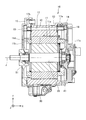
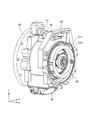
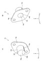
- FIG. 5 is a side sectional view showing the motor 10 of FIG. 1 cut along a plane orthogonal to the Z axis and passing through the central axis J. It is a perspective view which shows by removing the bracket 14 from the motor 10 of FIG. It is a perspective view which shows by removing the bracket 15 from the motor 10 of FIG. It is a perspective view which shows the head member 18 of FIG. It is a perspective view which shows the head member 19 of FIG.
- the direction in which the central axis J shown in FIG. 2 extends is simply referred to as "axial direction", the radial direction centered on the central axis J is simply referred to as “diameter direction”, and the central axis J is centered.
- the circumferential direction is simply called the “circumferential direction”.
- the right side in FIG. 2 is referred to as one side, and the left side in FIG. 2 is referred to as the other side.
- the side closer to the central axis J is called the inner side
- the side far from the central axis J is called the outer side.
- the XYZ coordinate system is shown as a three-dimensional Cartesian coordinate system as appropriate.
- the X-axis direction is a direction parallel to the central axis J and is a left-right direction in the side cross-sectional view shown in FIG.
- the Y-axis direction is a direction orthogonal to the X-axis direction, and is the vertical direction of the side sectional view shown in FIG.
- the Z-axis direction is a direction orthogonal to the X-axis direction and the Y-axis direction.
- the side facing the arrow shown in the figure is the + side
- the opposite side is the-side.
- extending or expanding in the axial direction means, in addition to the case of strictly extending or expanding in the axial direction (X-axis direction), a direction tilted within a range of less than 45 ° with respect to the axial direction. Including the case of extending or expanding to. Further, in the following description, extending or expanding in the radial direction means that the term extends or expands in the radial direction, that is, in the direction perpendicular to the axial direction (X-axis direction), and also in the radial direction. Including the case where it extends or spreads in a tilted direction within a range of less than 45 °.
- FIG. 1 is a perspective view of a motor according to the first embodiment of the present invention.
- FIG. 2 is a side sectional view showing the motor 10 of FIG. 1 cut along a plane orthogonal to the Z axis and passing through the central axis J.
- a motor which is an example of a rotating machine will be described.
- the motor 10 is an example of a rotating machine.
- the motor 10 includes a stator 11, a rotor 12, a frame 13, a bracket 14, and a bracket 15.
- the motor 10 has an oil pan 30 on the lower side of the frame 13 in the vertical direction.
- the stator 11 includes a stator core 11a and a coil 11b wound around the stator core 11a.
- the coil 11b has a coil end 11c projecting to one side in the axial direction of the stator core 11a and a coil end 11d projecting to the other side in the axial direction of the stator core 11a.
- the rotor 12 is arranged so as to face the stator 11 via an air gap.
- the rotor 12 is arranged inside the stator 11 in the radial direction.
- the rotor 12 has a shaft 22 arranged along the central axis J. The rotor 12 rotates around the shaft 22 as a rotation axis.
- the frame 13 covers the stator 11 from the outside in the radial direction.
- the frame 13 is, for example, die-cast aluminum.
- the bracket 14 covers one side of the frame 13 in the axial direction.
- the bracket 14 covers the frame 13 so as to close the opening on one side in the axial direction.
- the bracket 15 covers the other side of the frame 13 in the axial direction.
- the bracket 15 covers the frame 13 so as to close the opening on the other side in the axial direction.
- the shaft 22 penetrates the bracket 15.
- the motor 10 includes a bearing 41 that pivotally supports the shaft 22 on one side in the axial direction, and a bearing 51 that pivotally supports the shaft 22 on the other side in the axial direction.
- the bracket 14 fixes the bearing 41.
- the bracket 15 fixes the bearing 51.
- the bearing 41 and the bearing 51 pivotally support the shaft 22 so that the rotor 12 can rotate with the central axis J as the rotation axis.
- the frame 13 has an inflow port 16 on the outer side in the radial direction.
- the inflow port 16 is an inflow port for cooling oil. Cooling oil is an example of a cooling medium. Other known cooling media may be used instead of the cooling oil.
- the motor 10 causes the cooling oil to flow into the frame 13 from the inflow port 16 by, for example, a pump.
- the frame 13 has a flow path 17 that penetrates from the inflow port 16 to the opening 17a on one side in the axial direction.
- the opening 17a is an opening connected to the flow path 17.
- the motor 10 includes a head member 18 connected to the opening 17a.
- the head member 18 serves as a shower head.
- the frame 13 has a flow path 17 that penetrates from the inflow port 16 to the opening 17b on the other side in the axial direction.
- the opening 17b is an opening connected to the flow path 17.
- the motor 10 includes a head member 19 connected to the opening 17b.
- the head member 19 serves as a shower head.
- the flow path 17 penetrates from the opening 17a to the opening 17b.
- the cooling oil flowing in from the inflow port 16 goes to both the opening 17a and the opening 17b.
- FIG. 3 is a perspective view showing the motor 10 of FIG. 1 with the bracket 14 removed.
- the bracket 14 By removing the bracket 14 from the motor 10, the coil end 11c on one side in the axial direction of the stator 11 can be seen.
- the coil end 11c is simplified for easy viewing.
- the head member 18 is fixed to the frame 13 on the upper side of the coil end 11c in the vertical direction.
- FIG. 4 is a perspective view showing the motor 10 of FIG. 1 with the bracket 15 removed.
- the bracket 15 By removing the bracket 15 from the motor 10, the coil end 11d on the other side in the axial direction of the stator 11 can be seen.
- the coil end 11d is simplified for easy viewing.
- the head member 19 is fixed to the frame 13 on the upper side of the coil end 11d in the vertical direction.
- FIG. 5 is a perspective view showing the head member 18 of FIG. 5 (A) and 5 (B) show the head member 18 in different directions.
- the head member 18 has a plate portion 18a fixed to the frame 13 and a head portion 18b located on one side of the plate portion 18a in the axial direction.
- the plate portion 18a has a substantially quadrilateral flat plate shape.
- the plate portion 18a is fixed to the frame 13 in a direction in which the diagonal of the quadrilateral is orthogonal to the vertical direction and the vertical direction.
- the head portion 18b has a bottomed cylindrical shape.
- the head portion 18b may have a bottomed square cylinder shape or another shape.
- the plate portion 18a is fixed to the frame 13 by, for example, a bolt.
- the plate portion 18a has a through hole through which the head portion 18b penetrates.
- the plate portion 18a and the head portion 18b are integrated.
- the head portion 18b has a cylindrical side wall 18f and a disk-shaped side wall 18g corresponding to the bottom of the side wall 18f.
- the side wall 18f and the side wall 18g are integrated.
- the head portion 18b has an opening 18c that opens on the other side in the axial direction.
- the opening 18c is an opening connected to the flow path 18h formed by the inner wall of the side wall 18f.
- the head portion 18b is fixed to the frame 13 by aligning the opening 18c with the opening 17a of the frame 13.
- the flow path 18h is a flow path extending from the opening 17a to one side in the axial direction.
- the head portion 18b has a flow path 18e.
- the flow path 18e is connected to the flow path 18h and extends in a direction parallel to the straight line connecting the head member 18 and the coil end 11c.
- the cross-sectional area of the cooling oil flow is smaller in the flow path 18e than in the flow path 17.
- the cooling oil flowing in from the inflow port 16 is ejected from the flow path 18e toward the coil end 11c.
- the cooling oil that has passed through the coil end 11c is stored in the oil pan 30.
- the head member 18 has a plurality of flow paths 18e depending on the axial position and the circumferential position of the coil end 11c.
- the plurality of flow paths 18e cover the entire axial position and circumferential position of the coil end 11c, and the entire axial position and circumferential position of the coil end 11c can be cooled by the cooling oil.
- the head portion 18b has a flow path 18d.
- the flow path 18d is connected to the flow path 18h and extends in one axial direction.
- the cross-sectional area of the cooling oil flow is smaller in the flow path 18d than in the flow path 17.
- the cooling oil flowing in from the inflow port 16 is ejected from the flow path 18d toward the bearing 41.
- the cooling oil that has passed through the bearing 41 is stored in the oil pan 30.
- the head member 18 has a plurality of flow paths 18d according to the circumferential position of the bearing 41.
- the plurality of flow paths 18d cover the entire circumferential position of the bearing 41, and the entire circumferential position of the bearing 41 can be cooled by the cooling oil.
- FIG. 6 is a perspective view showing the head member 19 of FIG. 6 (A) and 6 (B) show the head member 19 in different directions.
- the head member 19 has a plate portion 19a fixed to the frame 13 and a head portion 19b located on the other side of the plate portion 19a in the axial direction.
- the plate portion 19a has a substantially quadrilateral flat plate shape.
- the plate portion 19a is fixed to the frame 13 in a direction in which the diagonal of the quadrilateral is neither orthogonal to nor parallel to the vertical direction.
- the head portion 19b has a bottomed cylindrical shape.
- the head portion 19b may have a bottomed square cylinder shape or another shape.
- the plate portion 19a is fixed to the frame 13 by, for example, a bolt.
- the plate portion 19a has a through hole through which the head portion 19b penetrates.
- the plate portion 19a and the head portion 19b are integrated.
- the head portion 19b has a cylindrical side wall 19f and a disk-shaped side wall 19g corresponding to the bottom of the side wall 19f.
- the side wall 19f and the side wall 19g are integrated.
- the head portion 19b has an opening 19c that opens on one side in the axial direction.
- the opening 19c is an opening connected to the flow path 19h formed on the inner wall of the side wall 19f.
- the head portion 19b is fixed to the frame 13 by aligning the opening 19c with the opening 17b of the frame 13.
- the flow path 19h is a flow path extending from the opening 17b to the other side in the axial direction.
- the head portion 19b has a flow path 19e.
- the flow path 19e is connected to the flow path 19h and extends in a direction parallel to the straight line connecting the head member 19 and the coil end 11d.
- the cross-sectional area of the cooling oil flow is smaller in the flow path 19e than in the flow path 17.
- the cooling oil flowing in from the inflow port 16 is ejected from the flow path 19e toward the coil end 11d.
- the cooling oil that has passed through the coil end 11d is stored in the oil pan 30.
- the head member 19 has a plurality of flow paths 19e depending on the axial position and the circumferential position of the coil end 11d.
- the plurality of flow paths 19e cover the entire axial position and circumferential position of the coil end 11d, and the entire axial position and circumferential position of the coil end 11d can be cooled by the cooling oil.
- the head portion 19b has a flow path 19d.
- the flow path 19d is connected to the flow path 19h and extends to the other side in the axial direction.
- the cross-sectional area of the cooling oil flow is smaller in the flow path 19d than in the flow path 17.
- the cooling oil flowing in from the inflow port 16 is ejected from the flow path 19d toward the bearing 51.
- the cooling oil that has passed through the bearing 51 is stored in the oil pan 30.
- the head member 19 has a plurality of flow paths 19d according to the circumferential position of the bearing 51.
- the plurality of flow paths 19d cover the entire circumferential position of the bearing 51, and the entire circumferential position of the bearing 51 can be cooled by the cooling oil.
- the cooling oil corresponding to the shapes of the coil ends 11c and 11d can be used.
- the spouts (flow paths 18e, 19e) may be provided in the head members 18 and 19, and the frame 13 can be shared by the stators 11 having a plurality of types.
- the head members 18 and 19 are dedicated members and small members, it is easy to process the spouts (flow paths 18e and 19e) according to the shapes of the coil ends 11c and 11d. Cooling oil can be ejected according to the shape of the coil end simply by exchanging the head member for each of the coil ends having a plurality of types of shapes.
- the through holes (flow paths 18d, 18e, 19d, 19e) of the head members 18 and 19 are smaller than the diameter of the oil passage (flow path 17) (the cross-sectional area of the flow is small), and therefore penetrate through. Oil can be ejected vigorously from the holes, and the coil ends 11c and 11d can be cooled efficiently.
- the head members 18 and 19 are located above the coil ends 11c and 11d in the vertical direction, oil can be ejected to the coil ends 11c and 11d without resisting gravity as much as possible, and the coil ends can be ejected. 11c and 11d can be cooled efficiently.
- the through holes extend in a direction parallel to the straight line connecting the head members 18 and 19 and the coil ends 11c and 11d, and thus the directions toward the coil ends 11c and 11d.
- the oil can be ejected to the coil ends 11c and 11d, and the coil ends 11c and 11d can be efficiently cooled.
- the bearings 41 and 51 can be cooled by the oil injected from the bearing cooling through holes. You can.
Landscapes
- Engineering & Computer Science (AREA)
- Power Engineering (AREA)
- Motor Or Generator Cooling System (AREA)
- Motor Or Generator Frames (AREA)
Abstract
本発明は、回転機に関する。本発明は、装置を大型化することなく取り扱い易く、コイルエンドに冷却オイルを行き渡らせることが可能な回転機を提供することを目的とする。モータ(10)は、ステータコア(11a)とステータコア(11a)に巻き回されたコイル(11b)とを有するステータ(11)と、ステータ(11)とエアギャップを介して対向して配置されたロータ(12)と、ステータ(11)を径方向外側から覆うフレーム(13)と、を備え、コイル(11b)は、ステータコア(11a)の軸方向一方側に突出する第一のコイルエンド(11c)を有し、フレーム(13)は、径方向外側の流入口(16)から軸方向一方側の第一の開口(17a)へと貫通する第一の流路(17)を有し、第一の開口(17a)と繋がり第一のコイルエンド(11c)に向けて貫通する第二の流路(18e)を有する第一のヘッド部材(18)を更に備える。
Description
本発明は、回転機に関する。
回転機は駆動により発熱して効率低下等を生じる虞があるため、冷却するのが望ましい。例えば、ステータのコイルエンドを冷却するために、コイルエンドに冷却オイルを流すことが行われている。
特許文献1では、ステータの上側に設置された冷却パイプを介して冷却オイルを流す構成を開示している。冷却パイプには分流パイプが接続され、分流パイプの先からコイルエンドに冷却オイルを掛けるようにしている。
特許文献1では、ステータの軸方向長さと同等の長さの冷却パイプが必要であり、ステータの上部に冷却パイプを配置するスペースが必要となる。また、特許文献1では、冷却パイプの先端に分流パイプを設けるが、分流パイプの長さのため、ステータの冷却に係る構成が大型化してしまうという問題もあった。また、分流パイプは組付け時に扱いづらく破損等の虞があった。更に、特許文献1では、4本の分流パイプを開示しているが、コイルエンドの各所に冷却オイルを行き渡らせようと4本よりも多くの分流パイプを設けると、更に大型化し、また破損の危険性が増すため、取り扱いが不便であるという問題があった。
本発明は、装置を大型化することなく取り扱い易く、コイルエンドに冷却オイルを行き渡らせることが可能な回転機を提供することを目的とする。
本発明の一態様に係る回転機は、ステータコアと前記ステータコアに巻き回されたコイルとを有するステータと、前記ステータとエアギャップを介して対向して配置されたロータと、前記ステータを径方向外側から覆うフレームと、を備え、前記コイルは、前記ステータコアの軸方向一方側に突出する第一のコイルエンドを有し、前記フレームは、径方向外側の流入口から軸方向一方側の第一の開口へと貫通する第一の流路を有し、前記第一の開口と繋がり前記第一のコイルエンドに向けて貫通する第二の流路を有する第一のヘッド部材を更に備える。
上記の一態様の回転機において、前記コイルは、前記ステータコアの軸方向他方側に突出する第二のコイルエンドを有し、前記第一の流路は、前記第一の開口から軸方向他方側の第二の開口へと貫通し、前記第二の開口と繋がり前記第二のコイルエンドに向けて貫通する第三の流路を有する第二のヘッド部材を更に備えてもよい。
上記の一態様の回転機において、前記第一のヘッド部材は、前記第一のコイルエンドの鉛直方向上側で前記フレームに固定され、前記第二のヘッド部材は、前記第二のコイルエンドの鉛直方向上側で前記フレームに固定されてもよい。
上記の一態様の回転機において、前記第二の流路は、前記第一の開口から軸方向一方側に延びる第四の流路と、前記第四の流路と繋がり、前記第一のヘッド部材と前記第一のコイルエンドとを結ぶ直線と平行な方向に延びる第五の流路と、を有し、前記第三の流路は、前記第二の開口から軸方向他方側に延びる第六の流路と、前記第六の流路と繋がり、前記第二のヘッド部材と前記第二のコイルエンドとを結ぶ直線と平行な方向に延びる第七の流路と、を有してもよい。
上記の一態様の回転機において、前記第一の流路、前記第二の流路、及び前記第三の流路は、前記流入口から流入した冷却媒体が流れる流路であり、冷却媒体の流れの断面積は、前記第一の流路よりも前記第五の流路が小さく、前記第一の流路よりも前記第七の流路が小さく、前記第一のヘッド部材は、前記第五の流路を複数有し、前記第二のヘッド部材は、前記第七の流路を複数有してもよい。
上記の一態様の回転機において、前記ロータの回転中心に配置されたシャフトと、前記シャフトを軸方向一方側で軸支する第一の軸受と、前記シャフトを軸方向他方側で軸支する第二の軸受と、を更に備え、前記第一のヘッド部材は、冷却媒体を前記第一の軸受に向けて噴出する第八の流路を有し、前記第二のヘッド部材は、冷却媒体を前記第二の軸受に向けて噴出する第九の流路を有してもよい。
本発明の一態様によれば、装置を大型化することなく取り扱い易く、コイルエンドに冷却オイルを行き渡らせることが可能な回転機を提供することが出来る。
以下、本発明の実施形態について図面を参照して説明する。実施形態では説明を分かり易くするため、本発明の主要部以外の構造や要素については、簡略化または省略して説明する。また、図面において、同じ要素には同じ符号を付す。なお、図面に示す各要素の形状、寸法などは模式的に示したもので、実際の形状、寸法などを示すものではない。
なお、以下の説明において、図2に示す中心軸Jが延びる方向を単に「軸方向」と呼び、中心軸Jを中心とする径方向を単に「径方向」と呼び、中心軸Jを中心とする周方向を単に「周方向」と呼ぶ。また、軸方向において、図2での右側を一方側と呼び、図2での左側を他方側と呼ぶ。また、径方向において、中心軸Jに近い側を内側と呼び、中心軸Jから遠い側を外側と呼ぶ。
また、図面においては、適宜3次元直交座標系としてXYZ座標系を示す。XYZ座標系において、X軸方向は、中心軸Jと平行な方向であって、図2に示す側断面図の左右方向とする。Y軸方向は、X軸方向と直交する方向であって、図2に示す側断面図の上下方向とする。Z軸方向は、X軸方向及びY軸方向と直交する方向とする。X軸方向、Y軸方向、Z軸方向の何れにおいても、図中に示される矢印の向く側を+側、反対側を-側とする。
また、以下の説明において、軸方向に延びる又は拡がる、とは、厳密に軸方向(X軸方向)に延びる又は拡がる場合に加えて、軸方向に対して、45°未満の範囲で傾いた方向に延びる又は拡がる場合も含む。また、以下の説明において、径方向に延びる又は拡がる、とは、厳密に径方向、すなわち、軸方向(X軸方向)に対して垂直な方向に延びる又は拡がる場合に加えて、径方向に対して、45°未満の範囲で傾いた方向に延びる又は拡がる場合も含む。
<第1実施形態>
図1は、本発明の第1実施形態に係るモータの斜視図である。図2は、図1のモータ10を、Z軸と直交し中心軸Jを通る面で切断して示す側断面図である。本実施形態では、回転機の一例であるモータについて説明する。モータ10は、回転機の一例である。
図1は、本発明の第1実施形態に係るモータの斜視図である。図2は、図1のモータ10を、Z軸と直交し中心軸Jを通る面で切断して示す側断面図である。本実施形態では、回転機の一例であるモータについて説明する。モータ10は、回転機の一例である。
モータ10は、ステータ11と、ロータ12と、フレーム13と、ブラケット14と、ブラケット15と、を備える。モータ10は、フレーム13の鉛直方向下側に、オイルパン30を有する。ステータ11は、ステータコア11aと、ステータコア11aに巻き回されたコイル11bと、を備える。コイル11bは、ステータコア11aの軸方向一方側に突出するコイルエンド11c及びステータコア11aの軸方向他方側に突出するコイルエンド11dを有する。ロータ12は、ステータ11とエアギャップを介して対向して配置される。ロータ12は、ステータ11の径方向内側に配置される。ロータ12は、中心軸Jに沿って配置されたシャフト22を有する。ロータ12はシャフト22を回転軸として回転する。
フレーム13は、ステータ11を径方向外側から覆う。フレーム13は、例えばアルミダイキャストである。ブラケット14は、フレーム13の軸方向一方側を覆う。ブラケット14は、フレーム13の軸方向一方側の開口を塞ぐように覆う。ブラケット15は、フレーム13の軸方向他方側を覆う。ブラケット15は、フレーム13の軸方向他方側の開口を塞ぐように覆う。シャフト22は、ブラケット15を貫通する。
モータ10は、シャフト22を軸方向一方側で軸支する軸受41、及びシャフト22を軸方向他方側で軸支する軸受51を備える。ブラケット14は、軸受41を固定する。ブラケット15は、軸受51を固定する。軸受41及び軸受51は、ロータ12が中心軸Jを回転軸として回転可能なように、シャフト22を軸支する。
フレーム13は、径方向外側に流入口16を有する。流入口16は、冷却オイルの流入口である。冷却オイルは、冷却媒体の一例である。冷却オイルの代わりに既知の他の冷却媒体を用いてもよい。モータ10は、例えばポンプによって流入口16からフレーム13内に冷却オイルを流入させる。フレーム13は、流入口16から軸方向一方側の開口17aへと貫通する流路17を有する。開口17aは、流路17に繋がる開口である。モータ10は、開口17aと繋がるヘッド部材18を備える。ヘッド部材18は、シャワーヘッドの役割を果たす。フレーム13は、流入口16から軸方向他方側の開口17bへと貫通する流路17を有する。開口17bは、流路17に繋がる開口である。モータ10は、開口17bと繋がるヘッド部材19を備える。ヘッド部材19は、シャワーヘッドの役割を果たす。流路17は、開口17aから開口17bへと貫通する。流入口16から流入した冷却オイルは、開口17a及び開口17bの両方へ向かう。
図3は、図1のモータ10からブラケット14を外して示す斜視図である。モータ10からブラケット14を外すことで、ステータ11の軸方向一方側のコイルエンド11cを見ることが出来る。なお、図3では、見やすさのため、コイルエンド11cを簡略化している。ヘッド部材18は、コイルエンド11cの鉛直方向上側でフレーム13に固定される。
図4は、図1のモータ10からブラケット15を外して示す斜視図である。モータ10からブラケット15を外すことで、ステータ11の軸方向他方側のコイルエンド11dを見ることが出来る。なお、図4では、見やすさのため、コイルエンド11dを簡略化している。ヘッド部材19は、コイルエンド11dの鉛直方向上側でフレーム13に固定される。
図5は、図3のヘッド部材18を示す斜視図である。図5(A)と図5(B)とで、ヘッド部材18の向きを変えて示している。ヘッド部材18は、フレーム13に固定するプレート部18aと、プレート部18aの軸方向一方側に位置するヘッド部18bと、を有する。プレート部18aは略四辺形の平板形状である。プレート部18aは、四辺形の対角線が鉛直方向及び鉛直方向と直交する方向で、フレーム13に固定される。ヘッド部18bは、有底円筒形状である。ヘッド部18bは、有底角筒形状であってもよいし、他の形状であってもよい。プレート部18aは、例えばボルトによってフレーム13に固定される。プレート部18aは、ヘッド部18bが貫通する貫通孔を有する。プレート部18aとヘッド部18bとは一体である。
ヘッド部18bは、円筒形状の側壁18fと、側壁18fの底に相当する円板形状の側壁18gと、を有する。側壁18fと側壁18gとは一体である。ヘッド部18bは、軸方向他方側に開口する開口18cを有する。開口18cは、側壁18fの内壁で形成される流路18hに繋がる開口である。ヘッド部18bは、開口18cとフレーム13の開口17aとを合わせて、フレーム13に固定される。流路18hは、開口17aから軸方向一方側に延びる流路である。
ヘッド部18bは、流路18eを有する。流路18eは、流路18hと繋がり、ヘッド部材18とコイルエンド11cとを結ぶ直線と平行な方向に延びる。冷却オイルの流れの断面積は、流路17よりも流路18eの方が小さい。流入口16から流入した冷却オイルは、流路18eからコイルエンド11cに向けて噴出される。コイルエンド11cを経由した冷却オイルはオイルパン30に貯留される。ヘッド部材18は、コイルエンド11cの軸方向位置及び周方向位置に応じて、流路18eを複数有する。複数の流路18eは、コイルエンド11cの軸方向位置及び周方向位置の全体をカバーし、冷却オイルによりコイルエンド11cの軸方向位置及び周方向位置の全体を冷却することが出来る。
ヘッド部18bは、流路18dを有する。流路18dは、流路18hと繋がり、軸方向一方側に延びる。冷却オイルの流れの断面積は、流路17よりも流路18dの方が小さい。流入口16から流入した冷却オイルは、流路18dから軸受41に向けて噴出される。軸受41を経由した冷却オイルはオイルパン30に貯留される。ヘッド部材18は、軸受41の周方向位置に応じて、流路18dを複数有する。複数の流路18dは、軸受41の周方向位置の全体をカバーし、冷却オイルにより軸受41の周方向位置の全体を冷却することが出来る。
図6は、図4のヘッド部材19を示す斜視図である。図6(A)と図6(B)とで、ヘッド部材19の向きを変えて示している。ヘッド部材19は、フレーム13に固定するプレート部19aと、プレート部19aの軸方向他方側に位置するヘッド部19bと、を有する。プレート部19aは略四辺形の平板形状である。プレート部19aは、四辺形の対角線が鉛直方向と直交せず平行でもない方向で、フレーム13に固定される。ヘッド部19bは、有底円筒形状である。ヘッド部19bは、有底角筒形状であってもよいし、他の形状であってもよい。プレート部19aは、例えばボルトによってフレーム13に固定される。プレート部19aは、ヘッド部19bが貫通する貫通孔を有する。プレート部19aとヘッド部19bとは一体である。
ヘッド部19bは、円筒形状の側壁19fと、側壁19fの底に相当する円板形状の側壁19gと、を有する。側壁19fと側壁19gとは一体である。ヘッド部19bは、軸方向一方側に開口する開口19cを有する。開口19cは、側壁19fの内壁で形成される流路19hに繋がる開口である。ヘッド部19bは、開口19cとフレーム13の開口17bとを合わせて、フレーム13に固定される。流路19hは、開口17bから軸方向他方側に延びる流路である。
ヘッド部19bは、流路19eを有する。流路19eは、流路19hと繋がり、ヘッド部材19とコイルエンド11dとを結ぶ直線と平行な方向に延びる。冷却オイルの流れの断面積は、流路17よりも流路19eの方が小さい。流入口16から流入した冷却オイルは、流路19eからコイルエンド11dに向けて噴出される。コイルエンド11dを経由した冷却オイルはオイルパン30に貯留される。ヘッド部材19は、コイルエンド11dの軸方向位置及び周方向位置に応じて、流路19eを複数有する。複数の流路19eは、コイルエンド11dの軸方向位置及び周方向位置の全体をカバーし、冷却オイルによりコイルエンド11dの軸方向位置及び周方向位置の全体を冷却することが出来る。
ヘッド部19bは、流路19dを有する。流路19dは、流路19hと繋がり、軸方向他方側に延びる。冷却オイルの流れの断面積は、流路17よりも流路19dの方が小さい。流入口16から流入した冷却オイルは、流路19dから軸受51に向けて噴出される。軸受51を経由した冷却オイルはオイルパン30に貯留される。ヘッド部材19は、軸受51の周方向位置に応じて、流路19dを複数有する。複数の流路19dは、軸受51の周方向位置の全体をカバーし、冷却オイルにより軸受51の周方向位置の全体を冷却することが出来る。
本実施形態によれば、フレーム13のコイルエンド11c、11d側の開口である開口17a及び17bにヘッド部材18及び19が固定されているので、コイルエンド11c、11dの形状に応じた冷却オイルの噴出口(流路18e、19e)は、ヘッド部材18及び19に設ければよく、フレーム13は、複数種類の形状のステータ11で共通化することが出来る。
また、ヘッド部材18及び19は、専用部材であり、小型部材であるので、コイルエンド11c、11dの形状に応じた噴出口(流路18e、19e)の加工が容易である。複数種類の形状のコイルエンドごとにヘッド部材を交換するだけで、コイルエンドの形状に応じた冷却オイルの噴出を行うことが出来る。
本実施形態によれば、ヘッド部材18及び19の貫通孔(流路18d、18e、19d、19e)は油路(流路17)の径よりも細い(流れの断面積が小さい)ので、貫通孔からオイルを勢いよく噴出することが出来、コイルエンド11c、11dを効率よく冷却することが出来る。
本実施形態によれば、ヘッド部材18及び19はコイルエンド11c、11dの鉛直方向上側に位置するので、重力に極力逆らわずに、オイルをコイルエンド11c、11dに噴出することが出来、コイルエンド11c、11dを効率よく冷却することが出来る。
本実施形態によれば、貫通孔(流路18e、19e)は、ヘッド部材18及び19とコイルエンド11c、11dとを結ぶ直線と平行な方向に延びるので、コイルエンド11c、11dに向いた方向にオイルを噴出することが出来、コイルエンド11c、11dを効率よく冷却することが出来る。
本実施形態によれば、ヘッド部材18及び19は、軸受冷却用貫通孔(流路18d、19d)を有するので、軸受冷却用貫通孔から噴射されたオイルにより軸受41、51を冷却することが出来る。
本発明は、上記実施形態に限定されることなく、本発明の趣旨を逸脱しない範囲において、種々の改良並びに設計の変更を行ってもよい。加えて、今回開示された実施形態は、全ての点で例示であって制限的なものではないと考えられるべきである。本発明の範囲は、上記した説明ではなくて特許請求の範囲によって示され、特許請求の範囲と均等の意味及び範囲内での全ての変更が含まれることが意図される。
本出願は、2020年3月19日に出願された日本特許出願である特願2020-048741号に基づく優先権を主張し、当該日本特許出願に記載されたすべての記載内容を援用する。
10…モータ、11…ステータ、12…ロータ、13…フレーム、18…ヘッド部材、19…ヘッド部材
Claims (6)
- ステータコアと前記ステータコアに巻き回されたコイルとを有するステータと、
前記ステータとエアギャップを介して対向して配置されたロータと、
前記ステータを径方向外側から覆うフレームと、
を備え、
前記コイルは、前記ステータコアの軸方向一方側に突出する第一のコイルエンドを有し、
前記フレームは、径方向外側の流入口から軸方向一方側の第一の開口へと貫通する第一の流路を有し、
前記第一の開口と繋がり前記第一のコイルエンドに向けて貫通する第二の流路を有する第一のヘッド部材を更に備える、
回転機。 - 前記コイルは、前記ステータコアの軸方向他方側に突出する第二のコイルエンドを有し、
前記第一の流路は、前記第一の開口から軸方向他方側の第二の開口へと貫通し、
前記第二の開口と繋がり前記第二のコイルエンドに向けて貫通する第三の流路を有する第二のヘッド部材を更に備える、
請求項1に記載の回転機。 - 前記第一のヘッド部材は、前記第一のコイルエンドの鉛直方向上側で前記フレームに固定され、
前記第二のヘッド部材は、前記第二のコイルエンドの鉛直方向上側で前記フレームに固定される、
請求項2に記載の回転機。 - 前記第二の流路は、前記第一の開口から軸方向一方側に延びる第四の流路と、前記第四の流路と繋がり、前記第一のヘッド部材と前記第一のコイルエンドとを結ぶ直線と平行な方向に延びる第五の流路と、を有し、
前記第三の流路は、前記第二の開口から軸方向他方側に延びる第六の流路と、前記第六の流路と繋がり、前記第二のヘッド部材と前記第二のコイルエンドとを結ぶ直線と平行な方向に延びる第七の流路と、を有する、
請求項2又は3に記載の回転機。 - 前記第一の流路、前記第二の流路、及び前記第三の流路は、前記流入口から流入した冷却媒体が流れる流路であり、
冷却媒体の流れの断面積は、前記第一の流路よりも前記第五の流路が小さく、前記第一の流路よりも前記第七の流路が小さく、
前記第一のヘッド部材は、前記第五の流路を複数有し、
前記第二のヘッド部材は、前記第七の流路を複数有する、
請求項4に記載の回転機。 - 前記ロータの回転中心に配置されたシャフトと、前記シャフトを軸方向一方側で軸支する第一の軸受と、前記シャフトを軸方向他方側で軸支する第二の軸受と、を更に備え、
前記第一のヘッド部材は、冷却媒体を前記第一の軸受に向けて噴出する第八の流路を有し、
前記第二のヘッド部材は、冷却媒体を前記第二の軸受に向けて噴出する第九の流路を有する、
請求項2から5のいずれか1項に記載の回転機。
Applications Claiming Priority (2)
| Application Number | Priority Date | Filing Date | Title |
|---|---|---|---|
| JP2020-048741 | 2020-03-19 | ||
| JP2020048741A JP6911960B1 (ja) | 2020-03-19 | 2020-03-19 | 回転機 |
Publications (1)
| Publication Number | Publication Date |
|---|---|
| WO2021187062A1 true WO2021187062A1 (ja) | 2021-09-23 |
Family
ID=76968010
Family Applications (1)
| Application Number | Title | Priority Date | Filing Date |
|---|---|---|---|
| PCT/JP2021/007563 Ceased WO2021187062A1 (ja) | 2020-03-19 | 2021-02-26 | 回転機 |
Country Status (2)
| Country | Link |
|---|---|
| JP (1) | JP6911960B1 (ja) |
| WO (1) | WO2021187062A1 (ja) |
Families Citing this family (2)
| Publication number | Priority date | Publication date | Assignee | Title |
|---|---|---|---|---|
| JP2023043439A (ja) * | 2021-09-16 | 2023-03-29 | 株式会社三共 | 遊技機 |
| JP7722881B2 (ja) * | 2021-09-16 | 2025-08-13 | 株式会社三共 | 遊技機 |
Citations (5)
| Publication number | Priority date | Publication date | Assignee | Title |
|---|---|---|---|---|
| WO2011101911A1 (ja) * | 2010-02-19 | 2011-08-25 | トヨタ自動車株式会社 | 動力伝達装置の潤滑構造 |
| KR20120058336A (ko) * | 2010-11-29 | 2012-06-07 | 엘지전자 주식회사 | 전동기 |
| JP2014107887A (ja) * | 2012-11-26 | 2014-06-09 | Meidensha Corp | 軸受潤滑油路構造 |
| WO2016067352A1 (ja) * | 2014-10-28 | 2016-05-06 | 三菱電機株式会社 | 回転電機 |
| CN106487161A (zh) * | 2015-08-26 | 2017-03-08 | 三菱电机株式会社 | 旋转电机 |
Family Cites Families (3)
| Publication number | Priority date | Publication date | Assignee | Title |
|---|---|---|---|---|
| JPH08149757A (ja) * | 1994-11-16 | 1996-06-07 | Meidensha Corp | 回転機の冷却構造 |
| JP3538947B2 (ja) * | 1995-03-10 | 2004-06-14 | 株式会社安川電機 | モータの冷却装置 |
| JP6947585B2 (ja) * | 2017-08-24 | 2021-10-13 | ファナック株式会社 | 回転子及び回転電機 |
-
2020
- 2020-03-19 JP JP2020048741A patent/JP6911960B1/ja active Active
-
2021
- 2021-02-26 WO PCT/JP2021/007563 patent/WO2021187062A1/ja not_active Ceased
Patent Citations (6)
| Publication number | Priority date | Publication date | Assignee | Title |
|---|---|---|---|---|
| WO2011101911A1 (ja) * | 2010-02-19 | 2011-08-25 | トヨタ自動車株式会社 | 動力伝達装置の潤滑構造 |
| KR20120058336A (ko) * | 2010-11-29 | 2012-06-07 | 엘지전자 주식회사 | 전동기 |
| JP2014107887A (ja) * | 2012-11-26 | 2014-06-09 | Meidensha Corp | 軸受潤滑油路構造 |
| WO2016067352A1 (ja) * | 2014-10-28 | 2016-05-06 | 三菱電機株式会社 | 回転電機 |
| CN107078606A (zh) * | 2014-10-28 | 2017-08-18 | 三菱电机株式会社 | 旋转电机 |
| CN106487161A (zh) * | 2015-08-26 | 2017-03-08 | 三菱电机株式会社 | 旋转电机 |
Also Published As
| Publication number | Publication date |
|---|---|
| JP6911960B1 (ja) | 2021-07-28 |
| JP2021151086A (ja) | 2021-09-27 |
Similar Documents
| Publication | Publication Date | Title |
|---|---|---|
| JP6609704B2 (ja) | 冷却媒体分配要素を有する組み立てられた中空ロータシャフト | |
| JP6333771B2 (ja) | 流体を流動させるための貫通孔が形成された主軸構造、電動機、および工作機械 | |
| JP2010263696A (ja) | モータの冷却構造 | |
| US11205939B2 (en) | Rotary electric machine | |
| CN110114962B (zh) | 用于电机的转子轴以及电机 | |
| WO2021187062A1 (ja) | 回転機 | |
| JP6164179B2 (ja) | 電動モータの冷却構造およびその製造方法 | |
| US20150015098A1 (en) | Rotor with cooling passage and motor having the same | |
| JP6268022B2 (ja) | 工作機械の主軸装置 | |
| JP7797948B2 (ja) | アキシャルギャップ型モータ | |
| JP6976449B2 (ja) | 電動機 | |
| JP6898887B2 (ja) | 回転電機および固定子冷却構造 | |
| JP2017184351A (ja) | 回転電機 | |
| JP6958655B2 (ja) | 回転機 | |
| JP2019054650A (ja) | 全閉外扇形回転電機 | |
| JP7233966B2 (ja) | 回転電機 | |
| JP2012196051A (ja) | 回転電機用エアダクトおよび回転電機ユニット | |
| US9831745B2 (en) | Electric machine | |
| JP2023084793A (ja) | 回転電機 | |
| JP2014212586A (ja) | 回転電機 | |
| JP2026046162A (ja) | 回転電機 | |
| WO2026058424A1 (ja) | モータ | |
| JP7800599B1 (ja) | 回転電機 | |
| JP7771825B2 (ja) | 回転電機 | |
| JP2021151055A (ja) | 回転機 |
Legal Events
| Date | Code | Title | Description |
|---|---|---|---|
| 121 | Ep: the epo has been informed by wipo that ep was designated in this application |
Ref document number: 21770431 Country of ref document: EP Kind code of ref document: A1 |
|
| NENP | Non-entry into the national phase |
Ref country code: DE |
|
| 122 | Ep: pct application non-entry in european phase |
Ref document number: 21770431 Country of ref document: EP Kind code of ref document: A1 |