WO2021187035A1 - 繊維成形体の製造方法 - Google Patents
繊維成形体の製造方法 Download PDFInfo
- Publication number
- WO2021187035A1 WO2021187035A1 PCT/JP2021/007039 JP2021007039W WO2021187035A1 WO 2021187035 A1 WO2021187035 A1 WO 2021187035A1 JP 2021007039 W JP2021007039 W JP 2021007039W WO 2021187035 A1 WO2021187035 A1 WO 2021187035A1
- Authority
- WO
- WIPO (PCT)
- Prior art keywords
- fiber
- fiber plate
- positioning
- pattern
- plate
- Prior art date
- Legal status (The legal status is an assumption and is not a legal conclusion. Google has not performed a legal analysis and makes no representation as to the accuracy of the status listed.)
- Ceased
Links
Images




Classifications
-
- B—PERFORMING OPERATIONS; TRANSPORTING
- B29—WORKING OF PLASTICS; WORKING OF SUBSTANCES IN A PLASTIC STATE IN GENERAL
- B29C—SHAPING OR JOINING OF PLASTICS; SHAPING OF MATERIAL IN A PLASTIC STATE, NOT OTHERWISE PROVIDED FOR; AFTER-TREATMENT OF THE SHAPED PRODUCTS, e.g. REPAIRING
- B29C70/00—Shaping composites, i.e. plastics material comprising reinforcements, fillers or preformed parts, e.g. inserts
- B29C70/04—Shaping composites, i.e. plastics material comprising reinforcements, fillers or preformed parts, e.g. inserts comprising reinforcements only, e.g. self-reinforcing plastics
- B29C70/28—Shaping operations therefor
- B29C70/40—Shaping or impregnating by compression not applied
- B29C70/42—Shaping or impregnating by compression not applied for producing articles of definite length, i.e. discrete articles
- B29C70/46—Shaping or impregnating by compression not applied for producing articles of definite length, i.e. discrete articles using matched moulds, e.g. for deforming sheet moulding compounds [SMC] or prepregs
-
- B—PERFORMING OPERATIONS; TRANSPORTING
- B27—WORKING OR PRESERVING WOOD OR SIMILAR MATERIAL; NAILING OR STAPLING MACHINES IN GENERAL
- B27N—MANUFACTURE BY DRY PROCESSES OF ARTICLES, WITH OR WITHOUT ORGANIC BINDING AGENTS, MADE FROM PARTICLES OR FIBRES CONSISTING OF WOOD OR OTHER LIGNOCELLULOSIC OR LIKE ORGANIC MATERIAL
- B27N3/00—Manufacture of substantially flat articles, e.g. boards, from particles or fibres
- B27N3/04—Manufacture of substantially flat articles, e.g. boards, from particles or fibres from fibres
-
- B—PERFORMING OPERATIONS; TRANSPORTING
- B27—WORKING OR PRESERVING WOOD OR SIMILAR MATERIAL; NAILING OR STAPLING MACHINES IN GENERAL
- B27N—MANUFACTURE BY DRY PROCESSES OF ARTICLES, WITH OR WITHOUT ORGANIC BINDING AGENTS, MADE FROM PARTICLES OR FIBRES CONSISTING OF WOOD OR OTHER LIGNOCELLULOSIC OR LIKE ORGANIC MATERIAL
- B27N3/00—Manufacture of substantially flat articles, e.g. boards, from particles or fibres
- B27N3/08—Moulding or pressing
- B27N3/18—Auxiliary operations, e.g. preheating, humidifying, cutting-off
-
- B—PERFORMING OPERATIONS; TRANSPORTING
- B27—WORKING OR PRESERVING WOOD OR SIMILAR MATERIAL; NAILING OR STAPLING MACHINES IN GENERAL
- B27N—MANUFACTURE BY DRY PROCESSES OF ARTICLES, WITH OR WITHOUT ORGANIC BINDING AGENTS, MADE FROM PARTICLES OR FIBRES CONSISTING OF WOOD OR OTHER LIGNOCELLULOSIC OR LIKE ORGANIC MATERIAL
- B27N3/00—Manufacture of substantially flat articles, e.g. boards, from particles or fibres
- B27N3/08—Moulding or pressing
- B27N3/20—Moulding or pressing characterised by using platen-presses
- B27N3/203—Moulding or pressing characterised by using platen-presses with heating or cooling means
-
- B—PERFORMING OPERATIONS; TRANSPORTING
- B27—WORKING OR PRESERVING WOOD OR SIMILAR MATERIAL; NAILING OR STAPLING MACHINES IN GENERAL
- B27N—MANUFACTURE BY DRY PROCESSES OF ARTICLES, WITH OR WITHOUT ORGANIC BINDING AGENTS, MADE FROM PARTICLES OR FIBRES CONSISTING OF WOOD OR OTHER LIGNOCELLULOSIC OR LIKE ORGANIC MATERIAL
- B27N5/00—Manufacture of non-flat articles
-
- B—PERFORMING OPERATIONS; TRANSPORTING
- B29—WORKING OF PLASTICS; WORKING OF SUBSTANCES IN A PLASTIC STATE IN GENERAL
- B29C—SHAPING OR JOINING OF PLASTICS; SHAPING OF MATERIAL IN A PLASTIC STATE, NOT OTHERWISE PROVIDED FOR; AFTER-TREATMENT OF THE SHAPED PRODUCTS, e.g. REPAIRING
- B29C33/00—Moulds or cores; Details thereof or accessories therefor
- B29C33/42—Moulds or cores; Details thereof or accessories therefor characterised by the shape of the moulding surface, e.g. ribs or grooves
- B29C33/424—Moulding surfaces provided with means for marking or patterning
-
- B—PERFORMING OPERATIONS; TRANSPORTING
- B29—WORKING OF PLASTICS; WORKING OF SUBSTANCES IN A PLASTIC STATE IN GENERAL
- B29C—SHAPING OR JOINING OF PLASTICS; SHAPING OF MATERIAL IN A PLASTIC STATE, NOT OTHERWISE PROVIDED FOR; AFTER-TREATMENT OF THE SHAPED PRODUCTS, e.g. REPAIRING
- B29C43/00—Compression moulding, i.e. applying external pressure to flow the moulding material; Apparatus therefor
- B29C43/02—Compression moulding, i.e. applying external pressure to flow the moulding material; Apparatus therefor of articles of definite length, i.e. discrete articles
- B29C43/021—Compression moulding, i.e. applying external pressure to flow the moulding material; Apparatus therefor of articles of definite length, i.e. discrete articles characterised by the shape of the surface
-
- B—PERFORMING OPERATIONS; TRANSPORTING
- B29—WORKING OF PLASTICS; WORKING OF SUBSTANCES IN A PLASTIC STATE IN GENERAL
- B29C—SHAPING OR JOINING OF PLASTICS; SHAPING OF MATERIAL IN A PLASTIC STATE, NOT OTHERWISE PROVIDED FOR; AFTER-TREATMENT OF THE SHAPED PRODUCTS, e.g. REPAIRING
- B29C43/00—Compression moulding, i.e. applying external pressure to flow the moulding material; Apparatus therefor
- B29C43/02—Compression moulding, i.e. applying external pressure to flow the moulding material; Apparatus therefor of articles of definite length, i.e. discrete articles
- B29C43/14—Compression moulding, i.e. applying external pressure to flow the moulding material; Apparatus therefor of articles of definite length, i.e. discrete articles in several steps
-
- B—PERFORMING OPERATIONS; TRANSPORTING
- B29—WORKING OF PLASTICS; WORKING OF SUBSTANCES IN A PLASTIC STATE IN GENERAL
- B29C—SHAPING OR JOINING OF PLASTICS; SHAPING OF MATERIAL IN A PLASTIC STATE, NOT OTHERWISE PROVIDED FOR; AFTER-TREATMENT OF THE SHAPED PRODUCTS, e.g. REPAIRING
- B29C43/00—Compression moulding, i.e. applying external pressure to flow the moulding material; Apparatus therefor
- B29C43/32—Component parts, details or accessories; Auxiliary operations
- B29C43/36—Moulds for making articles of definite length, i.e. discrete articles
-
- B—PERFORMING OPERATIONS; TRANSPORTING
- B29—WORKING OF PLASTICS; WORKING OF SUBSTANCES IN A PLASTIC STATE IN GENERAL
- B29C—SHAPING OR JOINING OF PLASTICS; SHAPING OF MATERIAL IN A PLASTIC STATE, NOT OTHERWISE PROVIDED FOR; AFTER-TREATMENT OF THE SHAPED PRODUCTS, e.g. REPAIRING
- B29C43/00—Compression moulding, i.e. applying external pressure to flow the moulding material; Apparatus therefor
- B29C43/32—Component parts, details or accessories; Auxiliary operations
- B29C43/52—Heating or cooling
-
- B—PERFORMING OPERATIONS; TRANSPORTING
- B29—WORKING OF PLASTICS; WORKING OF SUBSTANCES IN A PLASTIC STATE IN GENERAL
- B29C—SHAPING OR JOINING OF PLASTICS; SHAPING OF MATERIAL IN A PLASTIC STATE, NOT OTHERWISE PROVIDED FOR; AFTER-TREATMENT OF THE SHAPED PRODUCTS, e.g. REPAIRING
- B29C70/00—Shaping composites, i.e. plastics material comprising reinforcements, fillers or preformed parts, e.g. inserts
- B29C70/04—Shaping composites, i.e. plastics material comprising reinforcements, fillers or preformed parts, e.g. inserts comprising reinforcements only, e.g. self-reinforcing plastics
- B29C70/06—Fibrous reinforcements only
- B29C70/10—Fibrous reinforcements only characterised by the structure of fibrous reinforcements, e.g. hollow fibres
- B29C70/16—Fibrous reinforcements only characterised by the structure of fibrous reinforcements, e.g. hollow fibres using fibres of substantial or continuous length
- B29C70/18—Fibrous reinforcements only characterised by the structure of fibrous reinforcements, e.g. hollow fibres using fibres of substantial or continuous length in the form of a mat, e.g. sheet moulding compound [SMC]
-
- B—PERFORMING OPERATIONS; TRANSPORTING
- B29—WORKING OF PLASTICS; WORKING OF SUBSTANCES IN A PLASTIC STATE IN GENERAL
- B29C—SHAPING OR JOINING OF PLASTICS; SHAPING OF MATERIAL IN A PLASTIC STATE, NOT OTHERWISE PROVIDED FOR; AFTER-TREATMENT OF THE SHAPED PRODUCTS, e.g. REPAIRING
- B29C70/00—Shaping composites, i.e. plastics material comprising reinforcements, fillers or preformed parts, e.g. inserts
- B29C70/04—Shaping composites, i.e. plastics material comprising reinforcements, fillers or preformed parts, e.g. inserts comprising reinforcements only, e.g. self-reinforcing plastics
- B29C70/28—Shaping operations therefor
- B29C70/54—Component parts, details or accessories; Auxiliary operations, e.g. feeding or storage of prepregs or SMC after impregnation or during ageing
- B29C70/545—Perforating, cutting or machining during or after moulding
-
- B—PERFORMING OPERATIONS; TRANSPORTING
- B29—WORKING OF PLASTICS; WORKING OF SUBSTANCES IN A PLASTIC STATE IN GENERAL
- B29C—SHAPING OR JOINING OF PLASTICS; SHAPING OF MATERIAL IN A PLASTIC STATE, NOT OTHERWISE PROVIDED FOR; AFTER-TREATMENT OF THE SHAPED PRODUCTS, e.g. REPAIRING
- B29C43/00—Compression moulding, i.e. applying external pressure to flow the moulding material; Apparatus therefor
- B29C43/02—Compression moulding, i.e. applying external pressure to flow the moulding material; Apparatus therefor of articles of definite length, i.e. discrete articles
- B29C43/021—Compression moulding, i.e. applying external pressure to flow the moulding material; Apparatus therefor of articles of definite length, i.e. discrete articles characterised by the shape of the surface
- B29C2043/023—Compression moulding, i.e. applying external pressure to flow the moulding material; Apparatus therefor of articles of definite length, i.e. discrete articles characterised by the shape of the surface having a plurality of grooves
-
- B—PERFORMING OPERATIONS; TRANSPORTING
- B29—WORKING OF PLASTICS; WORKING OF SUBSTANCES IN A PLASTIC STATE IN GENERAL
- B29C—SHAPING OR JOINING OF PLASTICS; SHAPING OF MATERIAL IN A PLASTIC STATE, NOT OTHERWISE PROVIDED FOR; AFTER-TREATMENT OF THE SHAPED PRODUCTS, e.g. REPAIRING
- B29C43/00—Compression moulding, i.e. applying external pressure to flow the moulding material; Apparatus therefor
- B29C43/32—Component parts, details or accessories; Auxiliary operations
- B29C43/36—Moulds for making articles of definite length, i.e. discrete articles
- B29C2043/3602—Moulds for making articles of definite length, i.e. discrete articles with means for positioning, fastening or clamping the material to be formed or preforms inside the mould
-
- B—PERFORMING OPERATIONS; TRANSPORTING
- B29—WORKING OF PLASTICS; WORKING OF SUBSTANCES IN A PLASTIC STATE IN GENERAL
- B29C—SHAPING OR JOINING OF PLASTICS; SHAPING OF MATERIAL IN A PLASTIC STATE, NOT OTHERWISE PROVIDED FOR; AFTER-TREATMENT OF THE SHAPED PRODUCTS, e.g. REPAIRING
- B29C2793/00—Shaping techniques involving a cutting or machining operation
- B29C2793/0027—Cutting off
-
- B—PERFORMING OPERATIONS; TRANSPORTING
- B29—WORKING OF PLASTICS; WORKING OF SUBSTANCES IN A PLASTIC STATE IN GENERAL
- B29C—SHAPING OR JOINING OF PLASTICS; SHAPING OF MATERIAL IN A PLASTIC STATE, NOT OTHERWISE PROVIDED FOR; AFTER-TREATMENT OF THE SHAPED PRODUCTS, e.g. REPAIRING
- B29C2793/00—Shaping techniques involving a cutting or machining operation
- B29C2793/009—Shaping techniques involving a cutting or machining operation after shaping
-
- B—PERFORMING OPERATIONS; TRANSPORTING
- B29—WORKING OF PLASTICS; WORKING OF SUBSTANCES IN A PLASTIC STATE IN GENERAL
- B29C—SHAPING OR JOINING OF PLASTICS; SHAPING OF MATERIAL IN A PLASTIC STATE, NOT OTHERWISE PROVIDED FOR; AFTER-TREATMENT OF THE SHAPED PRODUCTS, e.g. REPAIRING
- B29C59/00—Surface shaping of articles, e.g. embossing; Apparatus therefor
- B29C59/02—Surface shaping of articles, e.g. embossing; Apparatus therefor by mechanical means, e.g. pressing
-
- B—PERFORMING OPERATIONS; TRANSPORTING
- B29—WORKING OF PLASTICS; WORKING OF SUBSTANCES IN A PLASTIC STATE IN GENERAL
- B29K—INDEXING SCHEME ASSOCIATED WITH SUBCLASSES B29B, B29C OR B29D, RELATING TO MOULDING MATERIALS OR TO MATERIALS FOR MOULDS, REINFORCEMENTS, FILLERS OR PREFORMED PARTS, e.g. INSERTS
- B29K2267/00—Use of polyesters or derivatives thereof as reinforcement
Definitions
- the present disclosure relates to a method for producing a fiber molded product in which a fiber material is compression molded.
- Patent Document 1 discloses an intake duct of an internal combustion engine formed by compression molding a non-woven fabric containing a thermoplastic resin binder as the fiber molded body.
- the peripheral wall of the intake duct has a high compression portion having a relatively large compression ratio and a low compression portion having a relatively small compression ratio.
- On the surface of the intake duct a pattern having a concave-convex shape is formed by these high-compression portions and low-compression portions.
- Such a fiber molded body is formed as follows, for example. First, in the outer shape molding step, a fiber plate made of a fiber material (nonwoven fabric) is compression-molded to form a fiber plate having a pattern on the outer surface. Then, in the cutting step, the unnecessary portion of the fiber plate is cut and removed by the cutting device.
- the fiber plate compression-molded in the outer shape molding process will shrink and deform in the subsequent process of temperature reduction.
- a fiber plate made of a fiber material has a characteristic that the variation in deformation mode in such contraction deformation tends to be large. Therefore, when the unnecessary portion of the fiber plate is cut in the cutting step in the formation of the fiber molded body, the relative position between the portion where the pattern is formed on the fiber plate and the portion cut by the cutting device tends to vary. It can be said. Then, such a variation in the relative position contributes to a decrease in the forming accuracy of the fiber molded product.
- the purpose of the book is to provide a method for manufacturing a fiber molded product capable of forming a fiber molded product having a pattern on the outer surface with high accuracy.
- the method for producing a fiber molded product for solving the above problems is a method for producing a fiber molded product having a pattern on the outer surface and compression molding of the fiber material, in which a fiber plate made of the fiber material is compression molded. , The outer shape forming step of forming the fiber plate into a predetermined outer shape while forming the pattern on the outer surface of the fiber plate, and compression molding the fiber plate to form an uneven shape on the outer surface of the fiber plate.
- the positioning part forming step of forming at least one positioning part used for positioning the fiber plate, and the fiber plate on which the pattern and the positioning part are formed are positioned on the cutting device by using the positioning part, and the above-mentioned
- a cutting step of cutting and removing a portion to be cut of a fiber plate by the cutting device is provided, and the pattern is formed in the outer shape molding step and the positioning portion is formed in the positioning portion molding step at the same time. ..
- a pattern and a positioning portion are simultaneously formed on the outer surface of the fiber plate. Therefore, it is possible to prevent the degree of contraction deformation of one of the portion where the pattern is formed and the portion where the positioning portion is formed in the fiber plate from becoming larger than the degree of contraction deformation of the other. Therefore, the variation in the pattern and the relative position of the positioning portion due to the difference in the degree of shrinkage of each portion of the fiber plate can be suppressed.
- the patterned portion of the fiber plate can be accurately arranged with respect to the cutting device by utilizing the positioning portion of the fiber plate. Therefore, the unnecessary portion of the fiber plate can be accurately cut by the cutting device so that the pattern is arranged at an appropriate position on the fiber molded body. Therefore, a fiber molded body having a pattern on the outer surface can be formed with high accuracy.
- FIG. 1 is a perspective view of a fiber molded product to which the manufacturing method of one embodiment is applied.
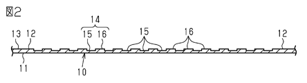
- FIG. 2 is a cross-sectional view of the fiber molded product along line 2-2 of FIG.
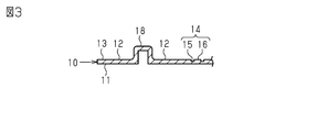
- FIG. 3 is a cross-sectional view of the fiber molded product along line 3-3 of FIG.
- FIG. 4 is a flowchart showing a manufacturing process of the fiber molded product.
- FIG. 5 is an explanatory diagram for explaining the first step.
- FIG. 6 is an explanatory diagram for explaining the second step.
- FIG. 7 is an explanatory diagram for explaining the third step.
- FIG. 8 is a perspective view of the fiber molded body according to the modified example.
- FIG. 9 is a perspective view of the fiber molded product according to another modified example.
- the fiber molded body 10 has a substantially flat plate shape having a rectangular outer shape.
- the fiber molded body 10 is formed of a compression-molded fiber material (nonwoven fabric).
- the non-woven fabric constituting the fiber molded body 10 is composed of, for example, fibers made of PET (polyethylene terephthalate).
- the fiber molded body 10 includes a square frame-shaped base portion 12 including an outer edge of the fiber molded body 10, and a pattern portion 14 surrounded by the base portion 12. As shown in FIGS. 2 and 3, one side surface (lower surface 11) of the fiber molded body 10 in the thickness direction is formed in a flat shape (planar shape) without a step. Further, of the other side surface (upper surface 13) of the fiber molded body 10 in the thickness direction, the portion corresponding to the base portion 12 is formed in a flat shape. As a result, the base portion 12 of the fiber molded body 10 is formed in a flat plate shape having a uniform thickness.
- the portion corresponding to the pattern portion 14 has an uneven shape.
- the pattern portion 14 is composed of a high compression portion 15 that is compression-molded at a relatively high compression rate and a low compression portion 16 that is compression-molded at a compression rate lower than that of the high compression portion 15.
- both the high compression portion 15 and the low compression portion 16 are formed in the shape of a square plate having the same outer shape as seen from the thickness direction of the fiber molded body 10.
- the high compression section 15 and the low compression section 16 are arranged in such a manner that they are alternately arranged in the opposite side direction of the square. Further, as shown in FIG. 2, the high compression section 15 is thinner than the low compression section 16.
- the high compression portion 15 and the low compression portion 16 are connected via a step at a portion of the upper surface 13 of the fiber molded body 10 corresponding to the pattern portion 14.
- the base portion 12 of the fiber molded body 10 is provided with positioning portions 17 and 18 forming a ridge having a U-shaped cross section.
- the positioning portions 17 and 18 extend along the outer edge of the pattern portion 14 between the pattern portion 14 and the outer edge of the base portion 12 in the fiber molded body 10.
- the first positioning portion 17 extends in the longitudinal direction of the fiber molded body 10
- the second positioning portion 18 extends in the lateral direction of the fiber molded body 10.
- These positioning portions 17 and 18 have a shape protruding from the upper surface 13 of the fiber molded body 10, and are used for positioning the fiber molded body 10 (specifically, the fiber plate 20 described later) at the time of manufacturing the fiber molded body 10. Used.
- step S1 the manufacturing procedure of the fiber molded body 10 of the present embodiment will be described.
- the first step is first executed (step S1).
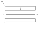
- a fiber plate 20 made of a non-woven fabric having a uniform thickness is hot-press molded by a hot press machine 21.
- the heat press machine 21 is a press processing machine having a die device 22 and a heating device (not shown) that heats the die device 22 with warm air or the like.
- the fiber plate 20 is compression-molded in a heated state.
- the fiber plate 20 is formed into a rectangular flat plate in the first step.
- the second step is executed (step S2 in FIG. 4).
- the fiber plate 20 is cold-press molded by the cold press machine 23.
- the cooling press machine 23 is a press processing machine having a die device 24 and a cooling device (not shown) that cools the die device 24 with cooling water or the like.
- the fiber plate 20 is compression-molded in a cooled state.
- the mold device 24 includes a fixed mold 25 and a movable mold 28.
- the fixed mold 25 is formed with a convex portion 26 for forming the pattern portion 14 and a concave portion 27 for forming the positioning portions 17 and 18.
- the movable mold 28 is formed with convex portions 29 for forming the positioning portions 17 and 18.
- the pattern portion 14 and the positioning portions 17 and 18 are formed on the fiber plate 20 by cold press forming the fiber plate 20 using a cooling press machine 23 having a mold device 24.
- the pattern portion 14 and the positioning portions 17 and 18 are formed at the same time.
- the fiber plate 20 formed in the second step is a portion in which the central portion in the extending direction forms the fiber molded body 10, and the square frame-shaped portion forming the outer edge in the extending direction is an unnecessary portion (cut target). Part). Further, in the present embodiment, the positioning portions 17 and 18 are formed on the portion of the fiber plate 20 other than the portion to be cut, that is, the portion forming the fiber molded body 10.
- the second step corresponds to the positioning portion forming step of forming the positioning portions 17 and 18 on the fiber plate 20, and the first step and the second step form a pattern on the outer surface of the fiber plate 20 while forming a pattern. This corresponds to an outer shape molding step of molding the fiber plate 20 into a predetermined outer shape.
- the third step is executed (step S3 in FIG. 4).
- the cutting device 30 cuts and removes the cut target portion PD of the fiber plate 20.
- the excision device 30 includes a movable type 31 and a fixed type 33.
- a cutting blade 32 made of a square annular Thomson blade is provided on the inner surface (lower surface in FIG. 7) of the movable mold 31.
- a first positioning convex portion 34 and a second positioning convex portion 35 are provided on the inner surface (upper surface in FIG. 7) of the fixed mold 33.
- the first positioning convex portion 34 is arranged at a position corresponding to the first positioning portion 17 of the fiber plate 20, and has a shape in which the first positioning portion 17 fits.
- the second positioning convex portion 35 is arranged at a position corresponding to the second positioning portion 18 of the fiber plate 20, and has a shape in which the second positioning portion 18 fits.
- the movable mold 31 and the fixed mold 33 of the cutting device 30 are separated from each other in a mold-opened state (state shown in FIG. 7), and then inside the positioning portions 17 and 18 of the fiber plate 20.
- the fiber plate 20 is placed on the fixed mold 33 in a manner in which the positioning protrusions 34, 35 of the fixed mold 33 are fitted.
- the fiber plate 20 is positioned with respect to the cutting device 30 (specifically, the fixed mold 33).
- the cutting blade 32 of the movable mold 31 cuts the cut target portion PD of the fiber plate 20.
- the third step corresponds to the excision step.
- the fiber molded body 10 (FIG. 1) having a pattern on the outer surface is manufactured through the first to third steps.
- the operation of the fiber molded product 10 of the present embodiment by the manufacturing method will be described.
- the temperature of the fiber molded body 10 (specifically, the fiber plate 20) becomes high in the hot press molding in the first step and cold press molding in the subsequent second step. It changes greatly, such as becoming lower in. Then, the fiber plate 20 is deformed (expanded and contracted) in response to such a temperature change.
- the formation timing of the pattern portion 14 on the fiber plate 20 and the formation timing of the positioning portions 17 and 18 are different, the portion where the pattern portion 14 is formed and the portion where the positioning portions 17 and 18 are formed on the fiber plate 20 and the portion where the positioning portions 17 and 18 are formed.
- the pattern portion 14 and the positioning portions 17 and 18 are simultaneously formed on the outer surface of the fiber plate 20 in the second step. Therefore, it is possible to prevent the degree of shrinkage deformation of one of the portion of the fiber plate 20 in which the pattern portion 14 is formed and the portion in which the positioning portions 17 and 18 are formed from being larger than the degree of contraction deformation of the other. Therefore, the variation in the relative positions of the pattern portion 14 and the positioning portions 17 and 18 due to the difference in the degree of shrinkage of each portion of the fiber plate 20 can be suppressed. As a result, the pattern portion 14 of the fiber plate 20 can be accurately arranged with respect to the fixed mold 25 of the cutting device 30 by utilizing the positioning portions 17 and 18 of the fiber plate 20.
- the unnecessary portion of the fiber plate 20 can be accurately cut by the cutting blade 32 of the movable type 28 of the cutting device 30 so that the pattern portion 14 is arranged at an appropriate position of the fiber molded body 10. .. Therefore, the fiber molded body 10 having a pattern on the outer surface can be formed with high accuracy.
- the temperature of the fiber plate 20 at the time of molding is high, so that each part of the fiber plate 20 due to the temperature drop after molding is formed.
- the degree of shrinkage deformation tends to increase, and the degree of shrinkage of each part of the fiber plate 20 tends to vary.
- the dimensional accuracy and the arrangement accuracy of the pattern portion 14 and the positioning portions 17 and 18 of the fiber plate 20 may be deteriorated.
- the pattern portion 14 and the positioning portions 17 and 18 are formed on the fiber plate 20 by the cold press molding in the second step.
- the fiber plate 20 at the time of molding the pattern portion 14 and the positioning portions 17 and 18 Since the temperature of the fiber plate 20 is low, shrinkage deformation of each part of the fiber plate 20 after their molding is suppressed. Therefore, the variation in the relative positions of the pattern portion 14 and the positioning portions 17 and 18 due to the difference in the degree of shrinkage of each portion of the fiber plate 20 can be suitably suppressed.
- the effects described below can be obtained.
- the pattern portion 14 and the positioning portions 17 and 18 are simultaneously formed on the outer surface of the fiber plate 20. Therefore, the fiber molded body 10 having a pattern on the outer surface can be formed with high accuracy.
- the pattern portion 14 and the positioning portions 17 and 18 are formed on the outer surface of the fiber plate 20 by the cold press molding in the second step. Therefore, the variation in the relative positions of the pattern portion 14 and the positioning portions 17 and 18 due to the difference in the degree of shrinkage of each portion of the fiber plate 20 can be suitably suppressed.
- a plurality of positioning portions 17 and 18 are formed on the fiber plate 20.
- the fiber plate 20 can be positioned at a plurality of parts with respect to the fixed mold 25 of the cutting device 30, so that the position of the fiber plate 20 can be performed more accurately than when the fiber plate 20 is positioned at only one place. Can be done.
- Positioning portions 17 and 18 are formed on the portion of the fiber plate 20 that is not cut in the third step, that is, the portion of the fiber plate 20 that forms the fiber molded body 10. Therefore, although the positioning portions 17 and 18 are formed on the fiber plate 20, it is not necessary to increase the outer shape of the fiber plate 20 in order to form the positioning portions 17 and 18. As a result, it is possible to prevent the PD of the portion to be cut of the fiber plate 20 from becoming large, so that it is possible to suppress a decrease in the yield required for manufacturing the fiber molded body 10.
- the uneven shape of the pattern portion 14, that is, the pattern of the fiber molded body 10 can be arbitrarily changed.
- the fiber plate 20 may be provided with three or more positioning portions. Further, if the fiber plate 20 can be properly positioned with respect to the cutting device 30, only one positioning portion may be provided on the fiber plate 20.
- -Positioning portions 17 and 18 may be formed on the cut target portion PD of the fiber plate 20.
- any shape can be adopted as long as the outer surface of the fiber plate 20 has an uneven shape and can be used for positioning the fiber plate 20.
- a convex portion protruding in an arbitrary shape (flat plate shape, columnar shape, polygonal columnar shape, etc.) different from the positioning portions 17 and 18 can be provided on the outer surface of the fiber plate 20 as a positioning portion.
- a flat plate-shaped first positioning portion 47 extending in the longitudinal direction and the thickness direction and a flat plate-shaped second positioning portion 48 extending in the lateral direction and the thickness direction are provided on the outer surface of the fiber plate 40.
- a groove having a shape corresponding to the protruding shape of the positioning portions 47 and 48 may be formed in the fixed mold 33 of the cutting device 30 (see FIG. 7).
- the fiber plate 40 in the third step, by placing the fiber plate 40 in the fixed mold 33 in a manner in which the positioning portions 47 and 48 of the fiber plate 40 are fitted into the grooves of the fixed mold 33 of the cutting device 30, the fibers with respect to the fixed mold 33 of the cutting device 30 are placed.
- the plate 40 can be positioned.
- through holes and recesses can be provided on the fiber plate as positioning portions.
- through holes 57 as positioning portions are provided at the four corners of the fiber plate 50 having a substantially rectangular flat plate shape.
- a convex portion having a shape corresponding to the shape of the through hole 57 may be formed at a position corresponding to each through hole 57 in the fixed mold 33 of the cutting device 30 (see FIG. 7).
- the fiber plate 50 is placed in the fixed mold 33 in a manner in which the convex portion of the fixed mold 33 of the cutting device 30 is fitted into the through hole 57 of the fiber plate 50, so that the fiber plate with respect to the fixed mold 33 of the cutting device 30 is fitted. 50 positioning can be performed.
- the through hole can be used as a caulking hole in a fixing structure for fixing the fiber molded body to the fixing target member through caulking.
- a positioning portion on the pattern portion 14.
- a part of the uneven pattern (specifically, the uneven shape) may function as the positioning portion.
- the manufacturing method according to the above embodiment is also a manufacturing method in which the first step (hot press molding) and the second step (cold press molding) are performed as a series of steps (outer shape molding step) using the same mold. Can be applied.
- the pattern portion and the positioning portion may be formed on the fiber plate through cold press molding in the outer shape forming step.
- the method of cutting the cut target portion PD of the fiber plate 20 is not limited to the method of cutting and removing with a cutting blade 32 made of a Thomson blade, but any method such as a method of cutting and removing with an ultrasonic cutter. An excision method can be adopted.
- the manufacturing method of the above embodiment is not limited to being applied to a fiber molded body having a substantially flat plate shape, and can be applied to a fiber molded body having an arbitrary outer shape.
- a fiber molded body include a fiber molded body having a semicircular portion extending in a semicircular cross section and a flange portion protruding radially outward from both ends of the semicircular portion in a flat plate shape.
- the pattern portion and the positioning portion are formed at the same time to form each part of the fiber plate. It is possible to suppress variations in the relative positions of the pattern portion and the positioning portion due to the difference in the degree of shrinkage.
Landscapes
- Engineering & Computer Science (AREA)
- Life Sciences & Earth Sciences (AREA)
- Mechanical Engineering (AREA)
- Manufacturing & Machinery (AREA)
- Wood Science & Technology (AREA)
- Forests & Forestry (AREA)
- Chemical & Material Sciences (AREA)
- Composite Materials (AREA)
- Textile Engineering (AREA)
- Dry Formation Of Fiberboard And The Like (AREA)
- Moulding By Coating Moulds (AREA)
- Casting Or Compression Moulding Of Plastics Or The Like (AREA)
Abstract
繊維成形体の製造方法は、外形成形工程、位置決め部成形工程、および切除工程を備える。外形成形工程では、繊維板(20)を圧縮成形して、同繊維板(20)の外面に模様を形成しつつ、当該繊維板(20)を所定の外形に成形する。位置決め部成形工程では、繊維板(14)を圧縮成形して、少なくとも一つの位置決め部(17,18)を形成する。切除工程では、繊維板(20)を位置決め部(17,18)を利用して切除装置(30)に位置決めするとともに、繊維板(30)の切除対象部分(PD)を切除装置(30)によって切断して除去する。繊維成形体の製造方法では、外形成形工程における模様の形成と、位置決め部成形工程における位置決め部(17,18)の形成とを同時に行う。
Description
本開示は、繊維材料が圧縮成形されてなる繊維成形体の製造方法に関するものである。
特許文献1には、上記繊維成形体として、熱可塑性樹脂バインダを含む不織布を圧縮成形することにより形成された内燃機関の吸気ダクトが開示されている。この吸気ダクトの周壁は、圧縮率が相対的に大きい高圧縮部と圧縮率が相対的に小さい低圧縮部とを有している。吸気ダクトの表面には、これら高圧縮部および低圧縮部により、凹凸形状をなす模様が形成されている。
こうした繊維成形体は、例えば次のように形成される。先ず、外形成形工程において、繊維材料(不織布)からなる繊維板が圧縮成形されて、外面に模様を有する繊維板が形成される。その後、切除工程において、繊維板の不要部分が切除装置によって切断されて除去される。
外形成形工程において圧縮成形された繊維板は、その後における温度低下の過程において収縮変形するようになる。繊維材料からなる繊維板は、そうした収縮変形における変形態様のばらつきが大きくなり易いといった特性を有する。そのため、上記繊維成形体の形成に際して、切除工程において繊維板の不要部分を切除するときには、繊維板における模様の形成される部分と上記切除装置によって切除される部分との相対位置にばらつきが生じやすいと云える。そして、こうした相対位置のばらつきは、繊維成形体の形成精度を低下させる一因になる。
本の目的は、外面に模様を有する繊維成形体を高い精度で形成することのできる繊維成形体の製造方法を提供することにある。
上記課題を解決するための繊維成形体の製造方法は、外面に模様を有するとともに繊維材料が圧縮成形されてなる繊維成形体の製造方法であって、繊維材料からなる繊維板を圧縮成形して、同繊維板の外面に前記模様を形成しつつ、当該繊維板を所定の外形に成形する外形成形工程と、前記繊維板を圧縮成形して、同繊維板の外面において凹凸形状をなして前記繊維板の位置決めに用いられる少なくとも一つの位置決め部を形成する位置決め部成形工程と、前記模様および前記位置決め部が形成された前記繊維板を前記位置決め部を利用して切除装置に位置決めするとともに、前記繊維板の切除対象部分を前記切除装置によって切断して除去する切除工程と、を備え、前記外形成形工程における前記模様の形成と、前記位置決め部成形工程における前記位置決め部の形成と、を同時に行う。
上記製造方法によれば、繊維板の外面に模様と位置決め部とが同時に形成される。そのため、繊維板における模様が形成された部分および位置決め部が形成された部分の一方の収縮変形の度合いが、他方の収縮変形の度合いよりも大きくなることが抑えられる。よって、繊維板の各部の収縮度合いの違いに起因する模様および位置決め部の相対位置のばらつきが抑えられる。これにより、繊維板の位置決め部を利用して、同繊維板の模様部分を切除装置に対して精度良く配置することができる。そのため、模様が繊維成形体の適正な位置に配置された状態になるように、切除装置によって繊維板の不要部分を正確に切除することができる。したがって、外面に模様を有する繊維成形体を高い精度で形成することができる。
以下、繊維成形体の製造方法の一実施形態について説明する。
先ず、本実施形態の製造方法が適用される繊維成形体について説明する。
図1に示すように、繊維成形体10は、外形が長方形状の略平板形状をなしている。この繊維成形体10は、圧縮成形された繊維材料(不織布)によって形成されている。繊維成形体10を構成する不織布は、例えば、PET(ポリエチレンテレフタレート)からなる繊維によって構成されている。
先ず、本実施形態の製造方法が適用される繊維成形体について説明する。
図1に示すように、繊維成形体10は、外形が長方形状の略平板形状をなしている。この繊維成形体10は、圧縮成形された繊維材料(不織布)によって形成されている。繊維成形体10を構成する不織布は、例えば、PET(ポリエチレンテレフタレート)からなる繊維によって構成されている。
繊維成形体10は、繊維成形体10の外縁を含む四角枠状のベース部12と、該ベース部12に囲まれた模様部14とを備えている。
図2および図3に示すように、繊維成形体10の厚さ方向における一方側の面(下面11)は、段差のない平らな形状(平面状)に形成されている。また、繊維成形体10の厚さ方向における他方側の面(上面13)のうち、ベース部12に対応する部分は、平面状に形成されている。これにより、繊維成形体10のベース部12は、均一な厚さの平板形状に形成されている。
図2および図3に示すように、繊維成形体10の厚さ方向における一方側の面(下面11)は、段差のない平らな形状(平面状)に形成されている。また、繊維成形体10の厚さ方向における他方側の面(上面13)のうち、ベース部12に対応する部分は、平面状に形成されている。これにより、繊維成形体10のベース部12は、均一な厚さの平板形状に形成されている。
繊維成形体10の上面13のうち、模様部14に対応する部分は、凹凸形状をなしている。詳しくは、模様部14は、比較的高い圧縮率で圧縮成形された高圧縮部15と、同高圧縮部15よりも低い圧縮率で圧縮成形された低圧縮部16とによって構成されている。図1に示すように、高圧縮部15および低圧縮部16は、共に繊維成形体10の厚さ方向から見た外形が同一の正四角形をなす四角板状に形成されている。高圧縮部15および低圧縮部16は、その正四角形の対辺方向において交互に並ぶ態様で配置されている。また図2に示すように、高圧縮部15は低圧縮部16よりも薄くなっている。高圧縮部15および低圧縮部16は、繊維成形体10の上面13のうちの模様部14に対応する部分において段差を介して連なっている。
図1および図3に示すように、繊維成形体10のベース部12には、断面U字状の突条をなす位置決め部17,18が設けられている。位置決め部17,18は、繊維成形体10における模様部14とベース部12の外縁との間において、同模様部14の外縁に沿って延設されている。第1位置決め部17は繊維成形体10の長手方向において延びており、第2位置決め部18は繊維成形体10の短手方向において延びている。これら位置決め部17,18は、繊維成形体10の上面13から突出する形状をなしており、繊維成形体10の製造時における同繊維成形体10(詳しくは、後述する繊維板20)の位置決めに用いられる。
以下、本実施形態の繊維成形体10の製造手順について説明する。
図4に示すように、繊維成形体10を製造する際には先ず、第1工程が実行される(ステップS1)。
図4に示すように、繊維成形体10を製造する際には先ず、第1工程が実行される(ステップS1)。
この第1工程では、図5に示すように、均一の厚さの不織布からなる繊維板20が熱プレス機21によって熱プレス成形される。熱プレス機21は、金型装置22と、同金型装置22を温風等によって加熱する加熱装置(図示略)とを有するプレス加工機である。第1工程では、繊維板20が加温された状態で圧縮成形される。本実施形態では、第1工程において、繊維板20が矩形平板状に成形される。
第1工程の後には、第2工程が実行される(図4のステップS2)。
この第2工程では、図6に示すように、上記繊維板20が冷却プレス機23によって冷プレス成形される。
この第2工程では、図6に示すように、上記繊維板20が冷却プレス機23によって冷プレス成形される。
冷却プレス機23は、金型装置24と、同金型装置24を冷却水等によって冷却する冷却装置(図示略)とを有するプレス加工機である。第2工程では、繊維板20が冷却された状態で圧縮成形される。金型装置24は固定型25および可動型28を備えている。固定型25には模様部14を成形するための凸部26と各位置決め部17,18を形成するための凹部27とが形成されている。可動型28には各位置決め部17,18を成形するための凸部29が形成されている。第2工程では、金型装置24を有する冷却プレス機23を用いて繊維板20を冷プレス成形することによって、同繊維板20に模様部14および位置決め部17,18が形成される。本実施形態では、第2工程において、模様部14の形成と位置決め部17,18の形成とが同時に行われる。
なお、第2工程で形成された繊維板20は、延在方向における中央部分が繊維成形体10をなす部分であり、延在方向における外縁を構成する四角枠状の部分が不要部分(切除対象部分)である。また本実施形態では、繊維板20における上記切除対象部分以外の部分、すなわち繊維成形体10をなす部分に位置決め部17,18が形成される。本実施形態では、第2工程が繊維板20に位置決め部17,18を形成する位置決め部成形工程に相当し、第1工程および第2工程が、繊維板20の外面に模様を形成しつつ、同繊維板20を所定の外形に成形する外形成形工程に相当する。
第2工程の後には、第3工程が実行される(図4のステップS3)。
この第3工程では、図7に示すように、切除装置30により、繊維板20の切除対象部分PDが切断されて除去される。
この第3工程では、図7に示すように、切除装置30により、繊維板20の切除対象部分PDが切断されて除去される。
切除装置30は可動型31および固定型33を備えている。可動型31の内面(図7における下面)には四角環状のトムソン刃からなる切断刃32が設けられている。また、固定型33の内面(図7における上面)には、第1位置決め凸部34および第2位置決め凸部35が設けられている。固定型33の内面において、第1位置決め凸部34は、繊維板20の第1位置決め部17に対応する位置に配置されており、同第1位置決め部17が嵌まる形状を有している。固定型33の内面において、第2位置決め凸部35は、繊維板20の第2位置決め部18に対応する位置に配置されており、同第2位置決め部18が嵌まる形状を有している。
第3工程では、先ず、切除装置30の可動型31と固定型33とが離間した型開き状態(図7に示す状態)にした上で、繊維板20の各位置決め部17,18の内部に固定型33の各位置決め凸部34,35を嵌める態様で、固定型33に繊維板20が置かれる。これにより、切除装置30(詳しくは、固定型33)に対する繊維板20の位置決めがなされる。そして、この状態で、切除装置30を型締め状態にすることにより、可動型31の切断刃32によって繊維板20の切除対象部分PDが切除される。なお本実施形態では、第3工程が切除工程に相当する。
本実施形態では、こうした第1工程~第3工程を通じて、外面に模様を有する繊維成形体10(図1)が製造される。
以下、本実施形態の繊維成形体10の製造方法による作用について説明する。
以下、本実施形態の繊維成形体10の製造方法による作用について説明する。
上述した繊維成形体10の製造に際して、同繊維成形体10(具体的には、繊維板20)の温度は、第1工程における熱プレス成形において高くなるとともに、その後の第2工程における冷プレス成形において低くなるといったように大きく変化する。そして、繊維板20は、そうした温度変化に応じて変形(膨張および収縮)するようになる。
そのため、繊維板20における模様部14の形成タイミングと位置決め部17,18の形成タイミングとが異なると、繊維板20における模様部14が形成された部分と位置決め部17,18が形成された部分との間で、その後の温度変化に伴う繊維板20の変形の度合いに違いが生じてしまう。これは、模様部14と位置決め部17,18との相対位置にばらつきを生じさせる一因になる。
そして、この場合には、繊維板20の位置決め部17,18を利用して同繊維板20を切除装置30の固定型25に位置決めしたときに、繊維板20の模様部14と切除装置30の可動型31の切断刃32との相対位置にばらつきを生じさせる。その結果、切断刃32による切断位置の設定精度、ひいては繊維成形体10の形成精度の低下を招いてしまう。
この点、本実施形態では、第2工程において、繊維板20の外面に模様部14と位置決め部17,18とが同時に形成される。そのため、繊維板20における模様部14が形成された部分および位置決め部17,18が形成された部分の一方の収縮変形の度合いが、他方の収縮変形の度合いよりも大きくなることが抑えられる。そのため、繊維板20の各部の収縮度合いの違いに起因する模様部14および位置決め部17,18の相対位置のばらつきが抑えられる。これにより、繊維板20の位置決め部17,18を利用して、同繊維板20の模様部14を切除装置30の固定型25に対して精度良く配置することができる。そのため、模様部14が繊維成形体10の適正な位置に配置された状態になるように、切除装置30の可動型28の切断刃32によって繊維板20の不要部分を正確に切除することができる。したがって、外面に模様を有する繊維成形体10を高い精度で形成することができる。
ここで仮に、熱プレス成形を通じて繊維板20に模様部14および位置決め部17,18を成形すると、成形時における繊維板20の温度が高いため、成形後の温度低下に伴う繊維板20の各部の収縮変形の度合いが大きくなり易く、同繊維板20の各部の収縮度合いにばらつきが生じ易くなってしまう。これにより、繊維板20の模様部14や位置決め部17,18の寸法精度や配置精度の低下を招くおそれがある。
本実施形態では、第2工程における冷プレス成形によって、繊維板20に模様部14と位置決め部17,18とが形成される。本実施形態によれば、熱プレス成形によって繊維板20の外面に模様部14および位置決め部17,18を形成する場合とは異なり、模様部14および位置決め部17,18の成形時における繊維板20の温度が低いため、それらの成形後における繊維板20の各部の収縮変形が抑えられる。したがって、繊維板20の各部の収縮度合いの違いに起因する模様部14および位置決め部17,18の相対位置のばらつきが好適に抑えられるようになる。
本実施形態によれば、以下に記載する効果が得られる。
(1)第2工程において、繊維板20の外面に模様部14と位置決め部17,18とが同時に形成される。そのため、外面に模様を有する繊維成形体10を高い精度で形成することができる。
(1)第2工程において、繊維板20の外面に模様部14と位置決め部17,18とが同時に形成される。そのため、外面に模様を有する繊維成形体10を高い精度で形成することができる。
(2)第2工程における冷プレス成形によって、繊維板20の外面に模様部14および位置決め部17,18が形成される。そのため、繊維板20の各部の収縮度合いの違いに起因する模様部14および位置決め部17,18の相対位置のばらつきが好適に抑えられるようになる。
(3)繊維板20に複数の位置決め部17,18が形成される。これにより、切除装置30の固定型25に対する繊維板20の位置決めを複数の部位で行うことができるため、一箇所のみで位置決めを行う場合と比較して、繊維板20の位置決めを精度良く行うことができる。
(4)繊維板20における第3工程において切除されない部分、すなわち繊維板20における繊維成形体10をなす部分に位置決め部17,18が形成される。そのため、繊維板20に位置決め部17,18が形成されるとはいえ、同位置決め部17,18の形成のために繊維板20の外形を大きくする必要がない。これにより、繊維板20の切除対象部分PDが大きくなることを抑えることができるため、繊維成形体10の製造にかかる歩留まりの低下を抑えることができる。
なお、上記実施形態は、以下のように変更して実施することができる。上記実施形態および以下の変更例は、技術的に矛盾しない範囲で互いに組み合わせて実施することができる。
・模様部14の凹凸形状、すなわち繊維成形体10の模様は任意に変更することができる。
・繊維板20に3つ以上の位置決め部を設けるようにしてもよい。また、切除装置30に対する繊維板20の位置決めを適正に行えるのであれば、繊維板20に位置決め部を一つのみ設けるようにしてもよい。
・繊維板20に3つ以上の位置決め部を設けるようにしてもよい。また、切除装置30に対する繊維板20の位置決めを適正に行えるのであれば、繊維板20に位置決め部を一つのみ設けるようにしてもよい。
・繊維板20の切除対象部分PDに、位置決め部17,18を形成するようにしてもよい。
・位置決め部17,18の形状は、繊維板20の外面において凹凸形状をなして同繊維板20の位置決めに用いることの可能な形状であれば、任意の形状を採用することができる。
・位置決め部17,18の形状は、繊維板20の外面において凹凸形状をなして同繊維板20の位置決めに用いることの可能な形状であれば、任意の形状を採用することができる。
例えば上記位置決め部17,18と異なる任意の形状(平板状、円柱状、多角柱状など)で突出する凸部を位置決め部として繊維板20の外面に設けることができる。図8に示す例では、繊維板40の外面に、長手方向および厚さ方向に延びる平板状の第1位置決め部47と、短手方向および厚さ方向に延びる平板状の第2位置決め部48とが設けられている。この場合には、切除装置30(図7参照)の固定型33に、位置決め部47,48の突出形状に対応する形状の溝を形成すればよい。第3工程において、繊維板40の位置決め部47,48を切除装置30の固定型33の溝に嵌める態様で同固定型33に繊維板40を置くことにより、切除装置30の固定型33に対する繊維板40の位置決めを行うことができる。
その他、貫通孔や凹部を位置決め部として繊維板に設けることもできる。図9に示す例では、長方形の略平板形状をなす繊維板50の四隅に、位置決め部としての貫通孔57が設けられている。この場合には、切除装置30(図7参照)の固定型33における各貫通孔57に対応する位置に、貫通孔57の形状に対応する形状の凸部を形成すればよい。第3工程において、繊維板50の貫通孔57に切除装置30の固定型33の凸部を嵌める態様で同固定型33に繊維板50を置くことにより、切除装置30の固定型33に対する繊維板50の位置決めを行うことができる。なお、繊維成形体に位置決め部としての貫通孔を形成する場合には、同貫通孔を、固定対象部材に繊維成形体をかしめ結合を通じて固定する固定構造におけるかしめ孔として利用することができる。
また、位置決め部を模様部14に設けることも可能である。この場合、繊維板20を位置決めすることが可能であれば、凹凸模様(具体的には、凹凸形状)の一部を位置決め部として機能させてもよい。
・上記実施形態にかかる製造方法は、第1工程(熱プレス成形)と第2工程(冷プレス成形)とを同一の金型を用いて一連の工程(外形成形工程)として行う製造方法にも適用することができる。この場合には、外形成形工程における冷プレス成形を通じて、繊維板に模様部と位置決め部とを形成するようにすればよい。
・第3工程において、繊維板20の切除対象部分PDを切除する方法は、トムソン刃からなる切断刃32によって切断および除去する方法に限らず、超音波カッターによって切断および除去する方法など、任意の切除方法を採用することができる。
・上記実施形態の製造方法は、略平板形状の繊維成形体に適用することに限らず、任意の外形の繊維成形体に適用することができる。そうした繊維成形体としては例えば、断面半円状で延びる半円部と同半円部の両端から径方向外方に平板状で突出するフランジ部とを有する繊維成形体を挙げることができる。この繊維成形体では、半円部の外面に模様部を形成するとともにフランジ部に位置決め部を形成する場合に、模様部の形成と位置決め部の形成とを同時に行うことにより、繊維板の各部の収縮度合いの違いに起因する模様部および位置決め部の相対位置のばらつきを抑えることができる。
10…繊維成形体
13…上面
14…模様部
17,47…第1位置決め部
18,48…第2位置決め部
20,40,50…繊維板
21…熱プレス機
23…冷却プレス機
30…切除装置
31…可動型
32…切断刃
57…貫通孔
13…上面
14…模様部
17,47…第1位置決め部
18,48…第2位置決め部
20,40,50…繊維板
21…熱プレス機
23…冷却プレス機
30…切除装置
31…可動型
32…切断刃
57…貫通孔
Claims (4)
- 外面に模様を有するとともに繊維材料が圧縮成形されてなる繊維成形体の製造方法であって、
繊維材料からなる繊維板を圧縮成形して、同繊維板の外面に前記模様を形成しつつ、当該繊維板を所定の外形に成形する外形成形工程と、
前記繊維板を圧縮成形して、同繊維板の外面において凹凸形状をなして前記繊維板の位置決めに用いられる少なくとも一つの位置決め部を形成する位置決め部成形工程と、
前記模様および前記位置決め部が形成された前記繊維板を前記位置決め部を利用して切除装置に位置決めするとともに、前記繊維板の切除対象部分を前記切除装置によって切断して除去する切除工程と、を備え、
前記外形成形工程における前記模様の形成と、前記位置決め部成形工程における前記位置決め部の形成と、を同時に行う、繊維成形体の製造方法。 - 前記外形成形工程は、前記繊維板を熱プレス成形する第1工程と、同第1工程の後に前記繊維板を冷プレス成形する第2工程と、を備え、
前記第2工程において、前記模様を形成する
請求項1に記載の繊維成形体の製造方法。 - 前記少なくとも一つの位置決め部は複数の位置決め部であり、
前記位置決め部成形工程において、前記複数の位置決め部を前記繊維板に形成する
請求項1または2に記載の繊維成形体の製造方法。 - 前記位置決め部成形工程では、前記繊維板における前記切除工程において切除されない部分に、前記少なくとも一つの位置決め部を形成する
請求項1~3のいずれか一項に記載の繊維成形体の製造方法。
Priority Applications (3)
| Application Number | Priority Date | Filing Date | Title |
|---|---|---|---|
| US17/910,140 US20230102585A1 (en) | 2020-03-18 | 2021-02-25 | Production method for fiber molded body |
| DE112021001699.7T DE112021001699T5 (de) | 2020-03-18 | 2021-02-25 | Herstellungsverfahren für faserformkörper |
| CN202180019580.7A CN115243852B (zh) | 2020-03-18 | 2021-02-25 | 纤维成形体的制造方法 |
Applications Claiming Priority (2)
| Application Number | Priority Date | Filing Date | Title |
|---|---|---|---|
| JP2020047827A JP7468023B2 (ja) | 2020-03-18 | 2020-03-18 | 繊維成形体の製造方法 |
| JP2020-047827 | 2020-03-18 |
Publications (1)
| Publication Number | Publication Date |
|---|---|
| WO2021187035A1 true WO2021187035A1 (ja) | 2021-09-23 |
Family
ID=77772011
Family Applications (1)
| Application Number | Title | Priority Date | Filing Date |
|---|---|---|---|
| PCT/JP2021/007039 Ceased WO2021187035A1 (ja) | 2020-03-18 | 2021-02-25 | 繊維成形体の製造方法 |
Country Status (5)
| Country | Link |
|---|---|
| US (1) | US20230102585A1 (ja) |
| JP (1) | JP7468023B2 (ja) |
| CN (1) | CN115243852B (ja) |
| DE (1) | DE112021001699T5 (ja) |
| WO (1) | WO2021187035A1 (ja) |
Citations (3)
| Publication number | Priority date | Publication date | Assignee | Title |
|---|---|---|---|---|
| JPH05193019A (ja) * | 1992-01-18 | 1993-08-03 | Dainippon Printing Co Ltd | 合成樹脂製蓋材の製造方法 |
| JP2012250395A (ja) * | 2011-06-01 | 2012-12-20 | Toyota Boshoku Corp | 成形装置 |
| JP2018178904A (ja) * | 2017-04-18 | 2018-11-15 | トヨタ紡織株式会社 | 内燃機関のインレットダクト |
Family Cites Families (6)
| Publication number | Priority date | Publication date | Assignee | Title |
|---|---|---|---|---|
| JP3188857B2 (ja) * | 1997-08-25 | 2001-07-16 | ニチハ株式会社 | 繊維成形板および建具の製造方法 |
| JP3217738B2 (ja) * | 1997-08-27 | 2001-10-15 | ニチハ株式会社 | 化粧繊維板および化粧繊維板の製造方法および建具 |
| JP4828658B1 (ja) * | 2011-03-14 | 2011-11-30 | 株式会社タケヒロ | 車両用防音材 |
| JP6460398B2 (ja) * | 2015-03-26 | 2019-01-30 | 本田技研工業株式会社 | Rtm成形方法 |
| US10464267B2 (en) * | 2017-06-29 | 2019-11-05 | GM Global Technology Operations LLC | Continuous fiber lattice for reinforcing polymeric composites |
| JP7052571B2 (ja) * | 2018-06-04 | 2022-04-12 | トヨタ自動車株式会社 | 成形装置および成形品の製造方法 |
-
2020
- 2020-03-18 JP JP2020047827A patent/JP7468023B2/ja active Active
-
2021
- 2021-02-25 CN CN202180019580.7A patent/CN115243852B/zh active Active
- 2021-02-25 WO PCT/JP2021/007039 patent/WO2021187035A1/ja not_active Ceased
- 2021-02-25 DE DE112021001699.7T patent/DE112021001699T5/de active Pending
- 2021-02-25 US US17/910,140 patent/US20230102585A1/en active Pending
Patent Citations (3)
| Publication number | Priority date | Publication date | Assignee | Title |
|---|---|---|---|---|
| JPH05193019A (ja) * | 1992-01-18 | 1993-08-03 | Dainippon Printing Co Ltd | 合成樹脂製蓋材の製造方法 |
| JP2012250395A (ja) * | 2011-06-01 | 2012-12-20 | Toyota Boshoku Corp | 成形装置 |
| JP2018178904A (ja) * | 2017-04-18 | 2018-11-15 | トヨタ紡織株式会社 | 内燃機関のインレットダクト |
Also Published As
| Publication number | Publication date |
|---|---|
| CN115243852B (zh) | 2023-06-30 |
| DE112021001699T5 (de) | 2023-01-26 |
| CN115243852A (zh) | 2022-10-25 |
| JP7468023B2 (ja) | 2024-04-16 |
| JP2021146572A (ja) | 2021-09-27 |
| US20230102585A1 (en) | 2023-03-30 |
Similar Documents
| Publication | Publication Date | Title |
|---|---|---|
| WO2021187035A1 (ja) | 繊維成形体の製造方法 | |
| JP2025069559A (ja) | 容器の設計方法、成形型の製造方法、および容器の製造方法 | |
| JP2000300929A (ja) | フィルタエレメントの製造方法 | |
| WO2016006403A1 (ja) | ラミネートフィルムの成形装置及びラミネートフィルムの成形方法 | |
| JP2014079990A (ja) | 断熱壁体の製造方法及び断熱壁体 | |
| JP5898567B2 (ja) | 中空構造体の製造方法、製造装置及び端面封止構造 | |
| JP2020073313A5 (ja) | 造形物の製造方法、表面シート及びスイッチ | |
| JP2004149369A (ja) | レンズ連接部材、及びレンズアレイの成形型 | |
| JPH024503A (ja) | プラスチックスの成形型 | |
| JP4019369B2 (ja) | 熱可塑性樹脂音響板の製造方法 | |
| JP2017136736A (ja) | シートプレス用成形金型 | |
| CN223405769U (zh) | 一种厚板热成型模具 | |
| TWI511861B (zh) | 殼體製造方法、殼體及電子裝置 | |
| KR20040067556A (ko) | 구면거울 제조방법 및 그 장치 | |
| US20170043523A1 (en) | Thermoplastic Shell Assembly Formed Integrally by Embedding and Sticking and Method for Manufacturing the Shell Assembly | |
| KR102196803B1 (ko) | 고무재질의 가스켓 제조방법 | |
| JPH01316252A (ja) | 光学素子の成形方法 | |
| JPH0522818B2 (ja) | ||
| JP2024157207A (ja) | 成形品の加工基準位置設定方法 | |
| RU138015U1 (ru) | Форма для вакуумной формовки | |
| JP2018202794A (ja) | 樹脂成形品の成形方法 | |
| TW202319208A (zh) | 具紋路面的模具及該模具製法 | |
| JP2001018288A (ja) | 合成樹脂シートの成形装置 | |
| KR101631919B1 (ko) | 팬 인서트 | |
| CN118342831A (zh) | 模具及镜片制备方法 |
Legal Events
| Date | Code | Title | Description |
|---|---|---|---|
| 121 | Ep: the epo has been informed by wipo that ep was designated in this application |
Ref document number: 21771207 Country of ref document: EP Kind code of ref document: A1 |
|
| 122 | Ep: pct application non-entry in european phase |
Ref document number: 21771207 Country of ref document: EP Kind code of ref document: A1 |