WO2021186954A1 - 処理装置、表示装置、半導体装置の製造方法、及びプログラム - Google Patents
処理装置、表示装置、半導体装置の製造方法、及びプログラム Download PDFInfo
- Publication number
- WO2021186954A1 WO2021186954A1 PCT/JP2021/004810 JP2021004810W WO2021186954A1 WO 2021186954 A1 WO2021186954 A1 WO 2021186954A1 JP 2021004810 W JP2021004810 W JP 2021004810W WO 2021186954 A1 WO2021186954 A1 WO 2021186954A1
- Authority
- WO
- WIPO (PCT)
- Prior art keywords
- alarm
- analysis
- cause
- processing
- analysis item
- Prior art date
- Legal status (The legal status is an assumption and is not a legal conclusion. Google has not performed a legal analysis and makes no representation as to the accuracy of the status listed.)
- Ceased
Links
Images







Classifications
-
- G—PHYSICS
- G08—SIGNALLING
- G08B—SIGNALLING SYSTEMS, e.g. PERSONAL CALLING SYSTEMS; ORDER TELEGRAPHS; ALARM SYSTEMS
- G08B29/00—Checking or monitoring of signalling or alarm systems; Prevention or correction of operating errors, e.g. preventing unauthorised operation
- G08B29/02—Monitoring continuously signalling or alarm systems
- G08B29/04—Monitoring of the detection circuits
-
- F—MECHANICAL ENGINEERING; LIGHTING; HEATING; WEAPONS; BLASTING
- F27—FURNACES; KILNS; OVENS; RETORTS
- F27D—DETAILS OR ACCESSORIES OF FURNACES, KILNS, OVENS OR RETORTS, IN SO FAR AS THEY ARE OF KINDS OCCURRING IN MORE THAN ONE KIND OF FURNACE
- F27D21/00—Arrangement of monitoring devices; Arrangement of safety devices
- F27D21/04—Arrangement of indicators or alarms
-
- G—PHYSICS
- G05—CONTROLLING; REGULATING
- G05B—CONTROL OR REGULATING SYSTEMS IN GENERAL; FUNCTIONAL ELEMENTS OF SUCH SYSTEMS; MONITORING OR TESTING ARRANGEMENTS FOR SUCH SYSTEMS OR ELEMENTS
- G05B23/00—Testing or monitoring of control systems or parts thereof
- G05B23/02—Electric testing or monitoring
- G05B23/0205—Electric testing or monitoring by means of a monitoring system capable of detecting and responding to faults
- G05B23/0218—Electric testing or monitoring by means of a monitoring system capable of detecting and responding to faults characterised by the fault detection method dealing with either existing or incipient faults
- G05B23/0224—Process history based detection method, e.g. whereby history implies the availability of large amounts of data
- G05B23/0227—Qualitative history assessment, whereby the type of data acted upon, e.g. waveforms, images or patterns, is not relevant, e.g. rule based assessment; if-then decisions
-
- G—PHYSICS
- G05—CONTROLLING; REGULATING
- G05B—CONTROL OR REGULATING SYSTEMS IN GENERAL; FUNCTIONAL ELEMENTS OF SUCH SYSTEMS; MONITORING OR TESTING ARRANGEMENTS FOR SUCH SYSTEMS OR ELEMENTS
- G05B23/00—Testing or monitoring of control systems or parts thereof
- G05B23/02—Electric testing or monitoring
- G05B23/0205—Electric testing or monitoring by means of a monitoring system capable of detecting and responding to faults
- G05B23/0218—Electric testing or monitoring by means of a monitoring system capable of detecting and responding to faults characterised by the fault detection method dealing with either existing or incipient faults
- G05B23/0224—Process history based detection method, e.g. whereby history implies the availability of large amounts of data
- G05B23/0227—Qualitative history assessment, whereby the type of data acted upon, e.g. waveforms, images or patterns, is not relevant, e.g. rule based assessment; if-then decisions
- G05B23/0235—Qualitative history assessment, whereby the type of data acted upon, e.g. waveforms, images or patterns, is not relevant, e.g. rule based assessment; if-then decisions based on a comparison with predetermined threshold or range, e.g. "classical methods", carried out during normal operation; threshold adaptation or choice; when or how to compare with the threshold
-
- G—PHYSICS
- G05—CONTROLLING; REGULATING
- G05B—CONTROL OR REGULATING SYSTEMS IN GENERAL; FUNCTIONAL ELEMENTS OF SUCH SYSTEMS; MONITORING OR TESTING ARRANGEMENTS FOR SUCH SYSTEMS OR ELEMENTS
- G05B23/00—Testing or monitoring of control systems or parts thereof
- G05B23/02—Electric testing or monitoring
- G05B23/0205—Electric testing or monitoring by means of a monitoring system capable of detecting and responding to faults
- G05B23/0259—Electric testing or monitoring by means of a monitoring system capable of detecting and responding to faults characterized by the response to fault detection
- G05B23/0267—Fault communication, e.g. human machine interface [HMI]
- G05B23/027—Alarm generation, e.g. communication protocol; Forms of alarm
-
- G—PHYSICS
- G05—CONTROLLING; REGULATING
- G05B—CONTROL OR REGULATING SYSTEMS IN GENERAL; FUNCTIONAL ELEMENTS OF SUCH SYSTEMS; MONITORING OR TESTING ARRANGEMENTS FOR SUCH SYSTEMS OR ELEMENTS
- G05B23/00—Testing or monitoring of control systems or parts thereof
- G05B23/02—Electric testing or monitoring
- G05B23/0205—Electric testing or monitoring by means of a monitoring system capable of detecting and responding to faults
- G05B23/0259—Electric testing or monitoring by means of a monitoring system capable of detecting and responding to faults characterized by the response to fault detection
- G05B23/0267—Fault communication, e.g. human machine interface [HMI]
- G05B23/0272—Presentation of monitored results, e.g. selection of status reports to be displayed; Filtering information to the user
-
- G—PHYSICS
- G05—CONTROLLING; REGULATING
- G05B—CONTROL OR REGULATING SYSTEMS IN GENERAL; FUNCTIONAL ELEMENTS OF SUCH SYSTEMS; MONITORING OR TESTING ARRANGEMENTS FOR SUCH SYSTEMS OR ELEMENTS
- G05B23/00—Testing or monitoring of control systems or parts thereof
- G05B23/02—Electric testing or monitoring
- G05B23/0205—Electric testing or monitoring by means of a monitoring system capable of detecting and responding to faults
- G05B23/0259—Electric testing or monitoring by means of a monitoring system capable of detecting and responding to faults characterized by the response to fault detection
- G05B23/0275—Fault isolation and identification, e.g. classify fault; estimate cause or root of failure
-
- H—ELECTRICITY
- H10—SEMICONDUCTOR DEVICES; ELECTRIC SOLID-STATE DEVICES NOT OTHERWISE PROVIDED FOR
- H10P—GENERIC PROCESSES OR APPARATUS FOR THE MANUFACTURE OR TREATMENT OF DEVICES COVERED BY CLASS H10
- H10P72/00—Handling or holding of wafers, substrates or devices during manufacture or treatment thereof
- H10P72/06—Apparatus for monitoring, sorting, marking, testing or measuring
- H10P72/0612—Production flow monitoring, e.g. for increasing throughput
-
- H—ELECTRICITY
- H10—SEMICONDUCTOR DEVICES; ELECTRIC SOLID-STATE DEVICES NOT OTHERWISE PROVIDED FOR
- H10P—GENERIC PROCESSES OR APPARATUS FOR THE MANUFACTURE OR TREATMENT OF DEVICES COVERED BY CLASS H10
- H10P95/00—Generic processes or apparatus for manufacture or treatments not covered by the other groups of this subclass
-
- F—MECHANICAL ENGINEERING; LIGHTING; HEATING; WEAPONS; BLASTING
- F27—FURNACES; KILNS; OVENS; RETORTS
- F27B—FURNACES, KILNS, OVENS OR RETORTS IN GENERAL; OPEN SINTERING OR LIKE APPARATUS
- F27B17/00—Furnaces of a kind not covered by any of groups F27B1/00 - F27B15/00
- F27B17/0016—Chamber type furnaces
- F27B17/0025—Chamber type furnaces specially adapted for treating semiconductor wafers
-
- G—PHYSICS
- G05—CONTROLLING; REGULATING
- G05B—CONTROL OR REGULATING SYSTEMS IN GENERAL; FUNCTIONAL ELEMENTS OF SUCH SYSTEMS; MONITORING OR TESTING ARRANGEMENTS FOR SUCH SYSTEMS OR ELEMENTS
- G05B2219/00—Program-control systems
- G05B2219/20—Pc systems
- G05B2219/26—Pc applications
- G05B2219/2602—Wafer processing
-
- G—PHYSICS
- G08—SIGNALLING
- G08B—SIGNALLING SYSTEMS, e.g. PERSONAL CALLING SYSTEMS; ORDER TELEGRAPHS; ALARM SYSTEMS
- G08B21/00—Alarms responsive to a single specified undesired or abnormal condition and not otherwise provided for
- G08B21/18—Status alarms
- G08B21/182—Level alarms, e.g. alarms responsive to variables exceeding a threshold
-
- H—ELECTRICITY
- H10—SEMICONDUCTOR DEVICES; ELECTRIC SOLID-STATE DEVICES NOT OTHERWISE PROVIDED FOR
- H10P—GENERIC PROCESSES OR APPARATUS FOR THE MANUFACTURE OR TREATMENT OF DEVICES COVERED BY CLASS H10
- H10P72/00—Handling or holding of wafers, substrates or devices during manufacture or treatment thereof
- H10P72/06—Apparatus for monitoring, sorting, marking, testing or measuring
- H10P72/0616—Monitoring of warpages, curvatures, damages, defects or the like
-
- H—ELECTRICITY
- H10—SEMICONDUCTOR DEVICES; ELECTRIC SOLID-STATE DEVICES NOT OTHERWISE PROVIDED FOR
- H10P—GENERIC PROCESSES OR APPARATUS FOR THE MANUFACTURE OR TREATMENT OF DEVICES COVERED BY CLASS H10
- H10P72/00—Handling or holding of wafers, substrates or devices during manufacture or treatment thereof
- H10P72/10—Handling or holding of wafers, substrates or devices during manufacture or treatment thereof using carriers specially adapted therefor, e.g. front opening unified pods [FOUP]
- H10P72/13—Horizontal boat type carrier whereby the substrates are vertically supported, e.g. comprising rod-shaped elements
Definitions
- This disclosure relates to a processing device, a display device, a method for manufacturing a semiconductor device, and a program.
- a means for detecting an abnormality in a device by statistical analysis technology or the like from information on a semiconductor manufacturing device is generally used.
- Patent Document 1 describes a method for managing the soundness of data
- Patent Document 2 describes a technique for anomaly analysis when a data abnormality occurs.
- the management device connected to the board processing device manages the operating state of the board processing device.
- more detailed data management is required than ever before, and it is becoming difficult for a management device that manages a plurality of substrate processing devices to sufficiently handle the data.
- the purpose of this disclosure is to provide a configuration that facilitates troubleshooting after an alarm is issued, reduces downtime, and contributes to productivity improvement.
- a processing device including a device controller having a storage unit for The device controller When the failure is detected, the alarm is output and It is configured so that the monitor data corresponding to the analysis item can be specified and the occurrence history of the alarm and the collection history of the monitor data corresponding to the analysis item including the time when the alarm occurs can be displayed.
- FIGS. 1 and 2 a substrate processing device 1 which is one of the processing devices in which the present disclosure is implemented will be described.
- the drawings used in the following description are all schematic, and the dimensional relationship of each element, the ratio of each element, and the like shown in the drawings do not always match the actual ones. Further, even between a plurality of drawings, the dimensional relationship of each element, the ratio of each element, and the like do not always match.
- the substrate processing device 1 includes a housing 2, and a front maintenance port 4 as an opening provided so as to be maintainable is opened in the lower part of the front wall 3 of the housing 2, and the front maintenance port 4 is a front surface. It is opened and closed by the maintenance door 5.
- a pod carry-in / carry-out outlet 6 is provided on the front wall 3 of the housing 2 so as to communicate the inside and outside of the housing 2.
- the pod carry-in / carry-out outlet 6 is opened / closed by the front shutter 7.
- a load port 8 is installed on the front front side of the pod loading / unloading outlet 6. The load port 8 is configured so that the mounted pod 9 can be aligned.
- the pod 9 is a closed-type substrate transfer container, and is carried on the load port 8 by an in-process transfer device (not shown), and is also carried out from the load port 8.
- a rotary pod shelf 11 is installed in the upper part of the housing 2 at a substantially central portion in the front-rear direction so that the rotary pod shelf 11 can store a plurality of pods 9. It is configured.
- the rotary pod shelf 11 includes a support column 12 that is vertically erected and intermittently rotated, and a plurality of stages of shelf boards 13 that are radially supported on the support column 12 at each position of the upper, middle, and lower stages.
- the shelf board 13 is configured so that a plurality of the pods 9 can be stored in a mounted state.
- a pod opener 14 is provided below the rotary pod shelf 11, and the pod opener 14 has a configuration in which the pod 9 can be placed and the lid of the pod 9 can be opened and closed.
- a pod transfer mechanism (container transfer mechanism) 15 is installed between the load port 8, the rotary pod shelf 11, and the pod opener 14, and the pod transfer mechanism 15 can hold the pod 9 and move up and down. It can move forward and backward in the horizontal direction, and is configured to be able to transport the pod 9 between the load port 8, the rotary pod shelf 11, and the pod opener 14.
- a sub-housing 16 is provided over the rear end in the lower part of the housing 2 at a substantially central portion in the front-rear direction.
- the front wall 17 of the sub-housing 16 has a pair of substrate loading / unloading outlets 19 for loading / unloading the wafer (hereinafter referred to as a substrate) 18 into the sub-housing 16 in two vertical stages.
- the pod openers 14 are provided side by side for the upper and lower board loading / unloading outlets 19.
- the pod opener 14 includes a mounting table 21 on which the pod 9 is placed, and an opening / closing mechanism 22 for opening and closing the lid of the pod 9.
- the pod opener 14 is configured so that the substrate entrance / exit of the pod 9 can be opened / closed by opening / closing the lid of the pod 9 placed on the mounting table 21 by the opening / closing mechanism 22.
- the sub-housing 16 constitutes a transfer chamber 23 that is airtight from the space (pod transfer space) in which the pod transfer mechanism 15 and the rotary pod shelf 11 are arranged.
- a substrate transfer mechanism 24 is installed in the front region of the transfer chamber 23, and the substrate transfer mechanism 24 has a required number of substrate mounting plates 25 (5 in the figure) on which the substrates 18 are mounted.
- the substrate mounting plate 25 is provided so as to be able to move linearly in the horizontal direction, rotate in the horizontal direction, and move up and down.
- the board transfer mechanism 24 is configured so that the board 18 can be loaded and unloaded from the boat 26.
- a standby unit 27 for accommodating and waiting for the boat 26 is configured, and a vertical processing furnace 28 is provided above the standby unit 27.
- the processing furnace 28 has a processing chamber 29 formed therein, and the lower end portion of the processing chamber 29 is a furnace opening portion, and the furnace opening portion is opened and closed by a furnace opening shutter 31.
- a boat elevator 32 for raising and lowering the boat 26 is installed between the right end of the housing 2 and the right end of the standby portion 27 of the sub-housing 16.
- a seal cap 34 as a lid is horizontally attached to the arm 33 connected to the lift of the boat elevator 32, the seal cap 34 vertically supports the boat 26, and the boat 26 is supported by the processing chamber 29. It is possible to airtightly close the furnace mouth part while it is charged in.
- the boat 26 is configured so that a plurality of substrates 18 can be aligned in the center thereof and held in multiple stages in a horizontal posture.
- a clean unit 35 is arranged at a position facing the boat elevator 32 side, and the clean unit 35 is composed of a supply fan and a dustproof filter so as to supply a clean atmosphere or clean air 36 which is an inert gas. There is.
- a notch alignment device (not shown) as a substrate matching device for aligning the positions of the substrates 18 in the circumferential direction is installed between the substrate transfer mechanism 24 and the clean unit 35.
- the clean air 36 blown out from the clean unit 35 is circulated to the notch alignment device (not shown), the substrate transfer mechanism 24, and the boat 26, and then sucked by a duct (not shown) and exhausted to the outside of the housing 2. It is configured so that it can be blown into the transfer chamber 23 by the clean unit 35.
- the pod carry-in / carry-out outlet 6 is opened by the front shutter 7.
- the pod 9 on the load port 8 is carried into the inside of the housing 2 by the pod transport mechanism 15 through the pod carry-in / carry-out port 6, and is placed on the designated shelf board 13 of the rotary pod shelf 11.
- the pod 9 is temporarily stored on the rotary pod shelf 11, and then transported from the shelf board 13 to one of the pod openers 14 by the pod transfer mechanism 15 and transferred to the mounting table 21 or the load port. It is directly transferred from 8 to the mounting table 21.
- the board loading / unloading outlet 19 is closed by the opening / closing mechanism 22, and the transfer chamber 23 is filled with clean air 36.
- the transfer chamber 23 is filled with nitrogen gas as clean air 36, so that the oxygen concentration is set to 20 ppm or less, which is much lower than the oxygen concentration inside the housing 2 (atmosphere).
- the opening side end face of the pod 9 mounted on the mounting table 21 is pressed against the opening edge of the substrate loading / unloading outlet 19 on the front wall 17 of the sub-housing 16, and the lid is removed by the opening / closing mechanism 22. , The wafer inlet / outlet is opened.
- the substrate 18 is taken out from the pod 9 by the substrate transfer mechanism 24, transferred to a notch alignment device (not shown), and the substrate 18 is aligned by the notch alignment device.
- the board transfer mechanism 24 carries the board 18 into the standby unit 27 behind the transfer chamber 23, and loads (charges) the board 26 into the boat 26.
- the board transfer mechanism 24 that delivered the board 18 to the boat 26 returns to the pod 9 and loads the next board 18 into the boat 26.
- the pod 9 is transported and transferred by the pod transfer mechanism 15, and the opening work of the pod 9 by the other pod opener 14 is simultaneously carried out.
- the furnace opening portion of the processing furnace 28 closed by the furnace opening shutter 31 is opened by the furnace opening shutter 31. Subsequently, the boat 26 is lifted by the boat elevator 32 and carried (loaded) into the processing chamber 29.
- the processing chamber 29 has a purging step (pre-purging step) in which the treatment chamber 29 is replaced with an inert gas at this timing (after loading).
- the processing chamber 29 is evacuated by a gas exhaust mechanism (not shown) so as to have a desired pressure (vacuum degree). Further, the processing chamber 29 is heated to a predetermined temperature by a heater driving unit (not shown) so as to have a desired temperature distribution.
- a processing gas controlled to a predetermined flow rate is supplied by a gas supply mechanism (not shown), and in the process of the processing gas flowing through the processing chamber 29, it comes into contact with the surface of the substrate 18 and is on the surface of the substrate 18. A predetermined process is carried out. Further, the processed gas after the reaction is exhausted from the processing chamber 29 by the gas exhaust mechanism.
- the gas supply mechanism supplies the inert gas from the inert gas supply source (not shown), the processing chamber 29 is replaced with the inert gas, and the pressure in the processing chamber 29 is increased. Is returned to normal pressure (after-purge process). Then, the boat 26 is lowered by the boat elevator 32 through the seal cap 34.
- the substrate 18 and the pod 9 are discharged to the outside of the housing 2 in the reverse procedure of the above description.
- the unprocessed substrate 18 is further loaded into the boat 26, and the batch processing of the substrate 18 is repeated.
- the control system 200 includes a device controller 201, a temperature control controller 211, a pressure control controller 212, a robot control controller 213, an MFC controller 214, and a Pump controller 215. Further, the device controller 201 functions as a data acquisition controller. The device controller 201 collects device data generated by the board processing device 1 and monitors the soundness of the device data.
- the apparatus data includes data related to substrate processing (for example, actually measured values) such as processing temperature, processing pressure, and flow rate of processing gas when the substrate processing apparatus 1 processes the substrate 18, and data related to the quality of the product substrate (for example, actual measurement values).
- substrate processing for example, actually measured values
- data related to the quality of the product substrate for example, actual measurement values
- the data for example, set value, measured value
- the components of the substrate processing apparatus 1 for example, quartz reaction tube, heater, valve, MFC, etc.
- Number of uses, usage time, etc. which includes monitor data generated by operating each component when the board processing device 1 processes the board 18, and various types generated by the board processing device 1.
- the measured value data is processed at a specific interval, for example, the raw waveform data as the specific interval (1 second, etc.) data from the start to the end of the recipe, or the measured value data at the specific interval at each step in the recipe.
- Statistic data is sometimes referred to as process data as data collected during recipe execution. This process data is included in the device data.
- the statistic data includes a maximum value, a minimum value, an average value, and the like.
- the device data also includes event data indicating various device events generated when the recipe is not executed, for example, when the board is not loaded into the device.
- the event data includes, for example, data indicating a maintenance history.
- the device controller 201 is electrically connected to the temperature control controller 211, the pressure control controller 212, the robot control controller 213, the MFC controller 214, and the Pump controller 215 by a LAN (Local Area Network) such as 100BASE-T. Therefore, the configuration is such that the data of each device can be sent and received, and each file can be downloaded and uploaded.
- LAN Local Area Network
- the device controller 201 is provided with a port as a mounting portion into which a recording medium (for example, a USB memory or the like) as an external storage device is inserted / removed.
- An OS Operating System
- a host computer and a management device are connected to the device controller 201 via, for example, a communication network. Therefore, even when the substrate processing apparatus 1 is installed in the clean room, the host computer can be arranged in an office or the like outside the clean room.
- the management device may be configured to be connected to the board processing device 1 via a LAN line and have a function of collecting device data from the device controller 201.
- the device controller 201 is configured so that it can collect device data, quantify the operating state of the device, and display it on the screen. Further, the device controller 201 is configured to be able to execute each function. A detailed description of the device controller 201 will be described later.
- a heating mechanism mainly composed of a heater, a temperature sensor, etc. is connected to the temperature control controller 211.
- the temperature control controller 211 is configured so that the temperature inside the processing furnace 28 can be adjusted by controlling the temperature of the heater of the processing furnace 28.
- the temperature control controller 211 is configured to be capable of controlling the switching (on / off) of the thyristor and controlling the electric power supplied to the heater strands.
- the pressure control controller 212 is mainly composed of a pressure sensor, an APC valve as a pressure valve, and a vacuum pump, and is connected to the pressure control controller 212.
- the pressure control controller 212 switches the opening of the APC valve and the vacuum pump (on / off) so that the pressure in the processing chamber 29 becomes the desired pressure at the desired timing based on the pressure value detected by the pressure sensor. ) Is configured to be controllable.
- the robot control controller 213 is connected to a robot mechanism mainly composed of a shading sensor and a robot.
- the robot control controller 213 is configured to be able to control the robot based on the sensor information detected by the shading sensor.
- the MFC controller 214 is composed of an MFC (Mass Flow Controller).
- Each of the temperature control controller 211, the pressure control controller 212, the robot control controller 213, and the MFC controller 214 is configured so as to be able to control each of them. Further, each of the temperature control controller 211, the pressure control controller 212, the robot control controller 213, and the MFC controller 214 sets the status, the alarm indicating the detected failure based on the sensor information, and the value of each connected sensor. It is configured so that it can be reported to the device controller 201 in real time as monitor data.
- a pump mechanism is connected to the Pump controller 215.
- the Pump controller 215 controls the pump mechanism and reports an alarm indicating a failure detected based on the sensor information and monitor data such as the pump state, current value, rotation speed, and back pressure to the device controller 201 in real time. It is structured so that it can be done.
- the device controller 201, the temperature control controller 211, the pressure control controller 212, the robot control controller 213, the MFC controller 214, and the Pump controller 215 use a normal computer system instead of a dedicated system. It is feasible. For example, by installing the program from a recording medium (flexible disk, CDROM, USB memory, etc.) in which the program for executing the above-mentioned processing is stored in a general-purpose computer, each controller that executes a predetermined processing is configured. be able to.
- a recording medium flexible disk, CDROM, USB memory, etc.
- the means for supplying these programs is arbitrary.
- it may be supplied via, for example, a communication line, a communication network, a communication system, or the like.
- the program may be posted on a bulletin board of a communication network, and the program may be provided by superimposing it on a carrier wave via the network. Then, by starting the program provided in this way and executing it in the same manner as other application programs under the control of the OS, a predetermined process can be executed.
- the device controller 201 includes a device control control unit 220, a device control storage unit 222 which is a hard disk, an operation display unit 227 including a display unit for displaying various information and an input unit for receiving various instructions from the operator, and board processing. It is configured so that it can include a device control communication unit 228 that communicates with the inside and outside of the device 1.
- the operator includes, in addition to the device operator, a device manager, a device engineer, a maintenance worker, and a worker.
- the device control control unit 220 includes a CPU (central processing unit) 224 as a processing unit and a memory (RAM, ROM, etc.) 226 as a temporary storage unit, and can be provided with a clock function (not shown). It is configured as a computer.
- each recipe file such as a recipe in which the processing conditions and processing procedures of the board are defined, a control program file for executing each of these recipe files, and parameters for executing the recipe are defined.
- various screen files including an input screen for inputting process parameters, various icon files, and the like (none of which are shown) are stored.
- the device control storage unit 222 stores monitor data including sensor information output from each controller and alarm history of an alarm indicating a failure detected by each controller based on the sensor information. Further, the device control storage unit 222 stores an alarm analysis table and an alarm cause pursuit table, which will be described later, respectively.
- the operation screen of the operation display unit 227 can be provided with each operation button as an input unit for inputting operation instructions to the board transfer system and the board processing system.
- the operation display unit 227 is configured so that an operation screen for operating the board processing device 1 can be displayed.
- the operation display unit 227 displays information based on the device data generated in the board processing device 1 on the operation screen via the operation screen.
- the operation screen of the operation display unit 227 is, for example, a touch panel using a liquid crystal display.
- the operation display unit 227 receives the input data (input instruction) of the operator from the operation screen and transmits the input data to the device controller 201. Further, the operation display unit 227 is instructed to execute an arbitrary board processing recipe (also referred to as a process recipe) among a recipe expanded in the memory (RAM) 226 or the like or a plurality of recipes stored in the device control storage unit 222. (Control instruction) is received and is configured to be able to be transmitted to the device control control unit 220.
- the operation display unit 227 displays alarm information including an alarm ID for identifying the type of alarm indicating the failure detected by the controller among the event data generated in the board processing device 1 on the operation screen. .. Further, the operation display unit 227 accepts the cause analysis request of the alarm including the alarm ID by the input data (input instruction) of the operator from the operation screen.
- the device controller 201 when the device controller 201 is started, various programs and the like are executed to expand each stored screen file and data table so that the device data can be read. Then, the device controller 201 is configured so that each screen showing the operating state of the device can be displayed on the operation display unit 227.
- the device control communication unit 228 is connected to a switching hub or the like.
- the device controller 201 includes various controllers (temperature control controller 211, pressure control controller 212, robot control controller 213, MFC controller 214, and Pump controller 215) in an external computer or board processing device 1 via a network. It is configured to be able to send and receive data.
- the device control control unit 220 When the device control control unit 220 receives the alarm cause analysis request from the operation display unit 227, it identifies candidates for analysis items for analyzing the cause of the alarm. The device control control unit 220 acquires monitor data corresponding to the specified analysis item from the device control storage unit 222 for the number of candidates listed as candidates, and monitors data corresponding to the specified analysis item. Is output to the operation display unit 227.
- the device controller 201 transmits device data such as the state of the board processing device 1 to an external higher-level computer via a network (not shown).
- the board processing of the board processing device 1 is controlled by the control system 200 based on each recipe file, each parameter file, etc. stored in the device control storage unit 222.
- the predetermined processing step is a case where a substrate processing step (here, a film forming step), which is one step of a semiconductor device manufacturing process, is carried out.
- a board processing recipe (process recipe) corresponding to the board processing to be performed is expanded into a memory such as RAM in the robot control controller 213, for example. Then, if necessary, an operation instruction is given from the device controller 201 to the robot control controller 213.
- the substrate processing step carried out in this manner includes at least a transfer step, a carry-in step, a film forming step, a carry-out step, and a recovery step.
- the device controller 201 issues a drive instruction for the board transfer mechanism 24 to the robot control controller 213. Then, while following the instructions from the robot control controller 213, the board transfer mechanism 24 starts the process of transferring the board 18 from the pod 9 on the mounting table 21 to the boat 26. This transfer process is carried out until the loading of all the planned substrates 18 into the boat 26 is completed.
- the inside of the processing chamber 29 is evacuated by the vacuum exhaust device so as to have a predetermined film forming pressure (vacuum degree) while following the instruction from the pressure control controller 212. Further, the inside of the processing chamber 29 is heated by the heater so as to reach a predetermined temperature while following the instruction from the temperature control controller 211. Subsequently, the rotation of the boat 26 and the substrate 18 by the rotation mechanism is started while following the instructions from the robot control controller 213. Then, while being maintained at a predetermined pressure and a predetermined temperature, a predetermined gas (processed gas) is supplied to a plurality of substrates 18 held on the boat 26, and a predetermined process (for example, film formation) is performed on the substrate 18. Processing) is done.
- a predetermined gas processed gas
- the boat 26 holding the processed substrate 18 is cooled extremely effectively by the clean air 36 blown from the clean unit 35. Then, for example, when cooled to 150 ° C. or lower, the treated substrate 18 is removed from the boat 26 and transferred to the pod 9, and then the new unprocessed substrate 18 is transferred to the boat 26.
- each controller detects the failure such as the failure based on the sensor information, and the failure is detected. Outputs an alarm indicating a failure. Then, when the device controller 201 receives the alarm cause analysis request including the alarm ID of the alarm, the alarm analysis process is executed.
- the device controller 201 acquires the alarm ID from the received cause analysis request for the alarm to be analyzed, and the alarm generation time, alarm ID, and alarm type stored in the device control storage unit 222 are hour. From the alarm history list table (see FIG. 13) displayed in the series, the alarm occurrence time corresponding to the acquired alarm ID is acquired.
- FIG. 13 illustrates alarm history information in which each item of the date and time when the alarm occurred, the alarm ID, and the message (alarm type) is recorded.
- the device controller 201 searches the alarm analysis table stored in the device control storage unit 222 for the presence or absence of data related to the acquired alarm ID.
- the alarm analysis table as shown in FIG. 6 is stored in the device control storage unit 222.
- an alarm ID for identifying an alarm a number of items indicating the number of analysis items used for analyzing the cause of the alarm represented by the alarm ID, and an analysis item for specifying the analysis item are shown.
- No. An alarm analysis table in which (number) is recorded is illustrated.
- the device controller 201 proceeds to step S104.
- the device controller 201 ends the alarm analysis process when the data related to the acquired alarm ID does not exist in the alarm analysis table stored in the device control storage unit 222.
- step S106 the device controller 201 determines whether or not the value of the counter matches the "number of items" included in the data searched in step S102. If the value of the counter matches the "number of items", the process proceeds to step S114. On the other hand, if the value of the counter does not match the "number of items", the process proceeds to step S108.
- the device controller 201 acquires "analysis item No.” included in the data searched in step S102 one by one.
- the device controller 201 refers to the alarm cause pursuit table as shown in FIG. 7 stored in the device control storage unit 222, and performs the cause analysis process corresponding to the “analysis item No.” acquired in step S108. conduct. Then, the device controller 201 acquires monitor data corresponding to the “analysis item No.” from the device control storage unit 222 before and after the alarm occurrence time acquired in step S100.
- the analysis item No. is displayed in the alarm cause investigation table.
- An example is shown in which data related to the cause analysis process that defines the process for acquiring the monitor data corresponding to is stored.
- the device controller 201 adds 1 to the value of the counter representing the number of analyzed items to be analyzed, and updates the counter.
- the device controller 201 has a display having at least an area for displaying the alarm information including the alarm history acquired in the step S100 and the graph showing the monitor data for each "analysis item No.” acquired in the step S110.
- the screen is displayed on the operation display unit 227.
- the threshold value When displaying the graph, the threshold value for determining the abnormality related to the monitor data and the time when the alarm occurred are displayed.
- the threshold value includes a threshold value related to monitor data and a threshold value related to deviation from the standard value of monitor data.
- the cause order is determined for each "analysis item No.” (see FIG. 8), and the determined cause order is displayed together with the graph.
- the monitor data of the alarm occurrence time is compared with the threshold value, and the deviation of the monitor data of the alarm occurrence time from the standard value is compared with the threshold value.
- the cause order of the analysis item is determined to be the first place. If there is an analysis item that does not exceed the threshold value but is close to the threshold value, the cause rank of the analysis item is determined to be second. For analysis items that are not close to the threshold value, the cause ranking of the analysis items is determined to be 3rd or higher. If none of the analysis items is close to the threshold value, no ranking is given for each analysis item.
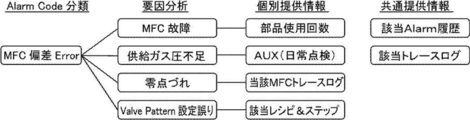
- FIG. 9 shows an FT factor diagram when the alarm type (corresponding to the Allarm Code classification) is an alarm based on an MFC (mass flow controller) gas flow rate deviation error (hereinafter referred to as an MFC deviation alarm). show.
- MFC mass flow controller
- MFC failure “insufficient supply gas pressure”, “zero point deviation”, and “valve pattern setting error” are defined as factor analysis when the alarm type is an MFC deviation alarm.
- number of parts used for analyzing "MFC failure”
- AUX (daily inspection)
- the "corresponding recipe & step” for analyzing the "corresponding MFC trace log” for analyzing the "zero point deviation” and the "Valve Pattern setting error” are defined.
- corresponding Allarm history” and “corresponding trace log” are defined as common provision information, and here, “common provision information” is data commonly used for factor analysis regardless of the alarm type. And “individually provided information” indicates data used for factor analysis of a specific alarm type.
- AUX (daily inspection) indicates sensor values of equipment attached to the equipment such as pressure of supply gas and flow rate of cooling water, which are not directly related to the process of the substrate processing apparatus 1.
- the “corresponding MFC trace log” shows the flow rate value of the MFC.
- “Corresponding recipe & step” is the setting value required for film formation such as gas, pressure, temperature, valve, etc. in each of the plurality of steps constituting the process recipe created to perform film formation. Shown. In addition, these setting values may be displayed on the screen display. This makes it possible to confirm whether or not there was a setting error in the step in which the alarm occurred.
- the "corresponding Alarm history” indicates that all the alarms generated by the substrate processing device 1 are recorded as a history for a certain period of time.
- the "corresponding trace log” indicates that data directly related to film formation such as gas (MFC flow rate monitor value), pressure (pressure gauge monitor value), and temperature are recorded in chronological order for a certain period of time. ..
- the device control storage unit 222 further has a plurality of FT factor diagrams created in advance for each alarm ID.
- the device controller 201 receives the cause analysis request and searches the device control storage unit 222 for the FT factor diagram corresponding to the alarm ID included in the cause analysis request.
- the device controller 201 is configured to be able to create an alarm analysis table and an alarm cause pursuit table based on the searched FT factor diagram.
- analysis items for the MFC deviation alarm for example, the number of times the parts of the relevant MFC are used, the pressure value of the supply gas of the relevant MFC, and the flow rate value of the relevant MFC are defined.
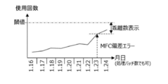
- FIG. 10 a graph showing the monitor data of the number of times the MFC has been used as shown in FIG. 10 is displayed.
- the change in the cumulative value of the number of times the MFC is used every day from the time before the alarm occurs for a predetermined period is displayed together with the time when the alarm occurs, the threshold value for determining an abnormality, and the number of deviations from the threshold value.
- An example is shown.
- the MFC limit usage number is set as the threshold value, and the number of deviations from the threshold value is displayed as the remaining number of times up to the limit usage number.
- the change in the cumulative value of the number of times the MFC is used may be displayed not for each day but for each processing batch. From this graph, it is possible to display the possibility that the MFC has become abnormal before the threshold value is reached.
- FIG. 11 a graph showing the monitor data of the pressure value of the supplied gas of the MFC as shown in FIG. 11 is displayed.
- the minimum pressure value of the supply gas of the MFC for each day from the time before the alarm occurs for a predetermined period is displayed together with the time when the alarm occurs, the threshold value for determining an abnormality, and the deviation value from the threshold value.
- the threshold value a threshold value related to the pressure value of the supplied gas of the corresponding MFC is set.
- the minimum pressure value of the supplied gas of the MFC may be displayed not for each day but for each processing batch. Further, it is possible to search for the number of pressure values of the supply gas near the threshold value and highlight and display the location on the graph. From this graph, it is possible to display that the pressure value of the supply gas may have temporarily decreased due to the convenience of the customer's equipment.
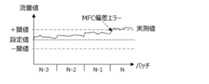
- a graph showing the monitor data of the gas flow rate value of the MFC as shown in FIG. 12 is displayed.
- the gas flow rate value of the MFC for each processing batch from a predetermined number of batches before the alarm occurrence time is measured together with the alarm occurrence time point, the set value, and the threshold value for abnormality determination according to the set value.
- An example to display is shown.
- the gas flow rate value the gas flow rate value of the step controlling the corresponding MFC is displayed. From this graph, it is possible to display how much the measured value deviates from the set value.
- the zero point deviation is gradually accumulated each time the batch processing is repeated, the base gas flow rate value rises or falls, and eventually a deviation error occurs.
- the monitor data any of gas, pressure, temperature, etc.
- the monitor data any of gas, pressure, temperature, etc.
- the MFC deviation alarm it is possible to determine whether the gas flow rate value gradually changes or suddenly changes.
- the threshold value for alarm issuance is set in advance for each analysis item, and when the threshold value is exceeded, the alarm for the analysis item is issued before the MFC deviation alarm. The operator can clearly determine the factor.
- the program analyzes whether there is an actually measured value near the threshold value, and determines and displays the order of the analysis items in descending order of probability of abnormality.
- the analysis item "MFC gas flow rate value” in which the monitor data exceeds the threshold value is determined to be the first place, and the analysis items “MFC usage count” and “MFC use count” which do not exceed the threshold value but are close to the threshold value are determined.
- “MFC supply pressure” is determined to be the second place and displayed.
- an arbitrary value for example, 90% of the threshold value
- the alarm history list table shown in FIG. 13 includes the occurrence of the deviation alarm of the first MFC. Then, in FIG. 13, in the area where the device data corresponding to the deviation alarm of the MFC is displayed as a graph, the analysis item "MFC usage count” and the analysis item "MFC supply pressure" for the alarm are the second largest cause of the alarm. , A time-series graph of monitor data corresponding to "MFC usage count” and "MFC supply pressure" is displayed. In FIG. 13, a time-series graph of monitor data showing the “MFC gas flow rate value” is displayed, with the analysis item “MFC gas flow rate value” for the alarm as the number one cause of the alarm.
- Example 2 Next, a case where a pressure deviation error occurs will be described as an example.
- the pressure value in the processing chamber 29 the number of times the APC valve is used, and the pump abnormality (pump current value, pump rotation speed, pump back pressure) are defined.
- the cause analysis request of the alarm including the alarm ID of the alarm based on the pressure deviation error (hereinafter referred to as the pressure deviation alarm) is received, the following three data are displayed on the screen.
- FIG. 14 a graph showing the pressure value in the processing chamber 29 as shown in FIG. 14 is displayed.
- the change in the minimum pressure value for each batch process from the time before the alarm occurs for a predetermined period is shown together with the time when the alarm occurs, the set value of the pressure value, and the threshold value for determining an abnormality with respect to the set value.
- An example to display is shown.
- FIG. 14 shows an example of displaying a change in the value at each time from a predetermined time before the alarm occurs. An alarm is issued when the pump current value, the pump rotation speed, and the pump back pressure each exceed the 3 ⁇ value five times in a row or fall below the -3 ⁇ value five times in a row.
- a graph showing the monitor data of the number of times the APC valve has been used is displayed.
- the change in the cumulative value of the number of times the APC valve is used every day from the time before the alarm occurs for a predetermined period is displayed together with the time when the alarm occurs, the threshold value for determining an abnormality, and the number of deviations from the threshold value. An example is shown.
- the alarm history list table shown in FIG. 14 includes the occurrence of a pressure deviation alarm. Then, in FIG. 14, in the area where the device data corresponding to the pressure deviation alarm is displayed as a graph, the analysis item "pressure value" for the alarm is regarded as the first cause of the alarm, and the monitor data corresponding to the "pressure value” is displayed. An example is shown in which the time series graph of is displayed. In FIG. 14, the analysis item “pump abnormality” for the alarm is ranked second, and the time series graph of the monitor data corresponding to the “pump abnormality” is displayed. In FIG. 14, a time-series graph of monitor data corresponding to the “APC usage count” is displayed with the analysis item “APC usage count” for the alarm in third place.
- the field of view can be expanded to the outside of the substrate processing device 1 and it helps to solve the problem at an early stage.
- the analysis items that cause the alarm are analyzed from the events, monitors, and alarms accumulated by the apparatus controller. Candidates are identified and the candidates are output in descending order of probability. As a result, it is possible to eliminate the dependence on the skill level of the operator as much as possible and troubleshoot in a short time, thereby shortening the downtime of the device and improving the productivity.
- troubleshooting is possible without depending on the skill level of the workers.
- equipment downtime can be reduced, which can contribute to improving the productivity of the substrate processing equipment.
- troubleshooting time can be shortened by managing pump troubles on the board processing device side as a cause search range.
- the substrate processing apparatus is applicable not only to a semiconductor manufacturing apparatus but also to an apparatus for processing a glass substrate such as an LCD (Liquid Crystal Display) apparatus. It can also be applied to various substrate processing devices such as an exposure device, a lithography device, a coating device, and a processing device using plasma.
- LCD Liquid Crystal Display
Landscapes
- Engineering & Computer Science (AREA)
- Physics & Mathematics (AREA)
- General Physics & Mathematics (AREA)
- Automation & Control Theory (AREA)
- Human Computer Interaction (AREA)
- Mechanical Engineering (AREA)
- General Engineering & Computer Science (AREA)
- Computer Security & Cryptography (AREA)
- Business, Economics & Management (AREA)
- Emergency Management (AREA)
- Testing And Monitoring For Control Systems (AREA)
- Design And Manufacture Of Integrated Circuits (AREA)
Abstract
Description
センサ情報を含むモニタデータ及び各コントローラが前記センサ情報に基づいて検知した障害を表すアラームを少なくとも含む装置データと、アラームの原因を解析するための解析項目を少なくとも含むアラーム解析テーブルと、を少なくとも記憶する記憶部を有する装置コントローラを含む処理装置であって、
前記装置コントローラは、
前記障害を検知したら前記アラームを出力し、
前記解析項目に対応するモニタデータを特定し、前記アラームの発生履歴と、アラーム発生時を含む前記解析項目に対応するモニタデータの収集履歴を表示するようことが可能なように構成されている。
次に、図3を参照して、操作部としての装置コントローラ201を中心とした制御システム200の機能構成について説明する。図3に示すように、制御システム200は、装置コントローラ201と、温度制御コントローラ211と、圧力制御コントローラ212と、ロボット制御コントローラ213と、MFCコントローラ214と、Pumpコントローラ215とを備えている。また、装置コントローラ201は、データ収集コントローラとして機能する。装置コントローラ201は、基板処理装置1で生成される装置データを収集して、該装置データの健全性を監視する。
次に、装置コントローラ201の構成を、図4を参照しながら説明する。
次に、本実施形態に係る基板処理装置1を用いて実施する、所定の処理工程を有する基板処理方法について説明する。ここで、所定の処理工程は、半導体デバイスの製造工程の一工程である基板処理工程(ここでは成膜工程)を実施する場合を例に挙げる。
装置コントローラ201からは、ロボット制御コントローラ213に対して、基板移載機構24の駆動指示が発せられる。そして、ロボット制御コントローラ213からの指示に従いつつ、基板移載機構24は載置台21上のポッド9からボート26への基板18の移載処理を開始する。この移載処理は、予定された全ての基板18のボート26への装填が完了するまで行われる。
基板18がボート26に装填されると、ボート26は、ロボット制御コントローラ213からの指示に従って動作するボートエレベータ32によって上昇されて、処理炉28内に形成される処理室29に装入(ボートロード)される。ボート26が完全に装入されると、ボートエレベータ32のシールキャップ34は、処理炉28のマニホールドの下端を気密に閉塞する。
その後は、処理室29内は、圧力制御コントローラ212からの指示に従いつつ、所定の成膜圧力(真空度)となるように真空排気装置によって真空排気される。また、処理室29内は、温度制御コントローラ211からの指示に従いつつ、所定の温度となるようにヒータによって加熱される。続いて、ロボット制御コントローラ213からの指示に従いつつ、回転機構によるボート26及び基板18の回転を開始する。そして、所定の圧力、所定の温度に維持された状態で、ボート26に保持された複数枚の基板18に所定のガス(処理ガス)を供給して、基板18に所定の処理(例えば成膜処理)がなされる。
ボート26に載置された基板18に対する成膜工程が完了すると、ロボット制御コントローラ213からの指示に従いつつ、その後、回転機構によるボート26及び基板18の回転を停止させ、ボートエレベータ32によりシールキャップ34を下降させてマニホールドの下端を開口させるとともに、処理済の基板18を保持したボート26を処理炉28の外部に搬出(ボートアンロード)する。
そして、処理済の基板18を保持したボート26は、クリーンユニット35から吹出されるクリーンエア36によって極めて効果的に冷却される。そして、例えば150℃以下に冷却されると、ボート26から処理済の基板18を脱装してポッド9に移載した後に、新たな未処理基板18のボート26への移載が行われる。
次に、装置コントローラ201が実行するアラーム解析処理の処理フローを、図5を主に用いて説明する。基板処理装置1を構成する部品に故障等の障害が発生して、基板処理装置1が稼働停止となった際に、各コントローラがセンサ情報に基づいて、この故障等の障害を検知し、該障害を表すアラームを出力する。そして、装置コントローラ201が、当該アラームのアラームIDを含むアラームの原因解析要求を受け付けると、アラーム解析処理は実行される。
まず、装置コントローラ201は、受け付けた解析対象のアラームの原因解析要求からアラームIDを取得すると共に、装置コント記憶部222に格納されている、発生したアラームの発生時刻、アラームID、アラーム種別が時系列に表示されているアラーム履歴一覧テーブル(図13参照)から、取得したアラームIDに対応するアラームの発生時刻を取得する。図13では、アラームが発生した年日時、アラームID、及びメッセージ(アラーム種別)の各項目が記録されているアラーム履歴情報が例示されている。
そして、装置コントローラ201は、装置コント記憶部222に格納されているアラーム解析テーブルから、取得したアラームIDに関するデータの有無を検索する。
そして、装置コントローラ201は、解析済みの解析項目の数を表すカウンタの値をクリアし、0にリセットする。
そして、装置コントローラ201は、カウンタの値が、上記ステップS102で検索されたデータに含まれる「項目数」と一致しているか否かを判定する。カウンタの値が、当該「項目数」と一致する場合には、ステップS114へ移行する。一方、カウンタの値が、当該「項目数」と一致しない場合には、ステップS108へ移行する。
そして、装置コントローラ201は、上記ステップS102で検索されたデータに含まれる「解析項目No.」を、一つずつ取得する。
そして、装置コントローラ201は、装置コント記憶部222に格納されている図7に示すようなアラーム原因追及テーブルを参照し、上記ステップS108で取得した「解析項目No.」に対応する原因解析処理を行う。そして、装置コントローラ201は、装置コント記憶部222から、当該「解析項目No.」に対応するモニタデータを、上記ステップS100で取得したアラーム発生時刻前後について取得する。
そして、装置コントローラ201は、解析済みの解析項目の数を表すカウンタの値を1加算し、カウンタを更新する。
そして、装置コントローラ201は、上記ステップS100で取得したアラーム履歴を含むアラーム情報と、上記ステップS110で取得した「解析項目No.」毎のモニタデータを示すグラフと、を少なくとも表示する領域を有する表示画面を操作表示部227に表示する。
次に、アラーム解析テーブルが、図9に示すFT(Fault Tree)要因図を基に製作される例について説明する。図9は、具体的には、アラーム種別(Alarm Code分類に該当)が、MFC(マスフローコントローラ)のガス流量偏差エラーに基づくアラーム(以下、MFC偏差アラームと称する。)のときのFT要因図を示す。
次に、圧力偏差エラーが発生した場合を例に説明する。
Claims (16)
- センサ情報を含むモニタデータ及び各コントローラが前記センサ情報に基づいて検知した障害を表すアラームを少なくとも含む装置データと、アラームの原因を解析するための解析項目を少なくとも含むアラーム解析テーブルと、を少なくとも記憶する記憶部を有する装置コントローラを含む処理装置であって、
前記装置コントローラは、
前記障害を検知したら前記アラームを出力し、
前記解析項目に対応するモニタデータを特定し、前記アラームの発生履歴と、アラーム発生時を含む前記解析項目に対応するモニタデータの収集履歴を表示することが可能なように構成されている処理装置。 - 前記装置コントローラは、前記アラーム発生時に、前記アラームに関連する装置データが複数ある場合、予め設定される閾値を超えた装置データをアラーム発生の要因として特定することが可能なように構成されている請求項1記載の処理装置。
- 前記装置コントローラは、前記アラーム発生時に、前記アラームに関連する装置データで予め設定される閾値を超えた装置データが無い場合、前記閾値に近い装置データをアラーム発生の要因として特定することが可能なように構成されている請求項1記載の処理装置。
- 前記装置コントローラは、前記アラームのうち排気制御の不良に起因するアラームを示す原因解析要求を受け付け、前記アラームの原因を解析する解析項目として、排気のためのポンプに関するセンサ情報を含むモニタデータを取得し、前記センサ情報を含むモニタデータを表示することが可能なように構成されている請求項1記載の処理装置。
- 更に、前記アラーム解析テーブルは、前記アラームを識別するためのアラームIDと、当該アラームIDが表すアラームの原因を解析するための解析項目の数を示す項目数と、当該解析項目を特定するための解析項目ナンバーとを含み、
前記装置コントローラは、前記アラームIDを含む前記アラームの原因解析要求を受け付けて、前記アラームIDで前記アラーム解析テーブルを検索して、前記項目数及び前記解析項目ナンバーを取得し、前記アラームの原因となる項目の候補を特定することが可能なように構成されている請求項1記載の処理装置。 - 前記装置コントローラは、前記項目数で定義される数の前記解析項目ナンバーで特定された解析項目に対応するモニタデータを取得することが可能なように構成されている請求項5記載の処理装置。
- 前記記憶部は、更に、前記解析項目ナンバーに関連付けられた原因解析処理を定義するアラーム原因追及テーブルを記憶し、
前記装置コントローラは、前記アラームIDに対応する前記解析項目ナンバーに基づいて前記原因解析処理を取得することが可能なように構成されている請求項5記載の処理装置。 - 前記装置コントローラは、前記解析項目ナンバーに関連付けされた原因解析処理の取得を、前記アラームIDに対応する前記項目数分だけ繰返すことが可能なように構成されている請求項7記載の処理装置。
- 前記装置コントローラは、更に、前記特定された解析項目の候補に対応するモニタデータを取得し、前記特定された解析項目の候補毎に、取得したモニタデータと、予め定められた閾値とを比較して、前記アラームの原因である順位を決定し、前記モニタデータを前記順位と共に表示画面に表示させることが可能なように構成されている請求項6記載の処理装置。
- 更に、前記アラーム解析テーブルは、前記アラームを識別するためのアラームIDと、当該アラームIDが表すアラームの原因を解析するための解析項目を特定するための解析項目ナンバーとを含み、
前記記憶部は、更に、前記アラームID毎に予め作成された複数のFT要因図を記憶し、
前記装置コントローラは、前記アラームの原因解析要求を受付けて、前記記憶部から、前記原因解析要求に含まれる前記アラームIDに対応する前記FT要因図を検索し、
前記検索された前記FT要因図に基づいて、前記アラーム解析テーブルと、前記解析項目ナンバーに関連付けられた原因解析処理を定義するアラーム原因追及テーブルを作成することが可能なように構成されている請求項1記載の処理装置。 - 前記装置データは、基板を処理する処理室の雰囲気を排気する排気装置に関連する装置データであって、ポンプ電流、ポンプ回転数、及びポンプ背圧からなる群から選択される一つ以上の装置データである請求項1記載の処理装置。
- 前記装置コントローラは、前記ポンプ電流、前記ポンプ回転数、及び前記ポンプ背圧からなる群から少なくとも一つの前記装置データの平均値が所定回数連続して予め定められた閾値から外れるとアラームを発生させることが可能なように構成されている請求項11記載の処理装置。
- 更に、前記処理室と、前記排気装置と、を少なくとも備え、
前記処理室と前記排気装置が同じフロアに配置されることが可能なように構成されている請求項11記載の処理装置。 - センサ情報を含むモニタデータ及び前記センサ情報に基づいて検知した障害を表すアラームを少なくとも含む装置データと、アラームの原因を解析するための解析項目を少なくとも含むアラーム解析テーブルを少なくとも記憶する工程と、
前記障害を検知し前記アラームを出力する工程と、
前記解析項目に対応するモニタデータを特定し、前記アラームの発生履歴と、アラーム発生時を含む前記解析項目に対応するモニタデータの収集履歴を表示する工程と、
を含む半導体装置の製造方法。 - センサ情報を含むモニタデータを取得しつつ基板を処理する工程を有する半導体装置の製造方法であって、
前記モニタデータ及び前記センサ情報に基づいて検知した障害を表すアラームを少なくとも含む装置データと、アラームの原因を解析するための解析項目を少なくとも含むアラーム解析テーブルを少なくとも記憶する工程と、
前記障害を検知し前記アラームを出力する工程と、
前記解析項目に対応するモニタデータを特定し、前記アラームの発生履歴と、アラーム発生時を含む前記解析項目に対応するモニタデータの収集履歴を表示する工程と、
を含む半導体装置の製造方法。 - センサ情報を含むモニタデータ及び前記センサ情報に基づいて検知した障害を表すアラームを少なくとも含む装置データと、アラームの原因を解析するための解析項目を少なくとも含むアラーム解析テーブルを少なくとも記憶する記憶部を有する装置コントローラに、
前記障害を検知したら前記アラームを出力させる手順と、
前記解析項目に対応するモニタデータを特定し、前記アラームの発生履歴と、アラーム発生時を含む前記解析項目に対応するモニタデータの収集履歴を表示する手順と、
を実行させるためのプログラム。
Priority Applications (4)
| Application Number | Priority Date | Filing Date | Title |
|---|---|---|---|
| KR1020227026648A KR20220123103A (ko) | 2020-03-19 | 2021-02-09 | 처리 장치, 표시 방법, 반도체 장치의 제조 방법 및 프로그램 |
| CN202180008253.1A CN114946011B (zh) | 2020-03-19 | 2021-02-09 | 处理装置、显示方法、半导体器件的制造方法及记录介质 |
| US17/882,172 US12080149B2 (en) | 2020-03-19 | 2022-08-05 | Processing apparatus, display method, method of manufacturing semiconductor device and non-transitory computer-readable recording medium |
| US18/782,775 US20240378989A1 (en) | 2020-03-19 | 2024-07-24 | Processing apparatus, display method, method of manufacturing semiconductor device and non-transitory computer-readable recording medium |
Applications Claiming Priority (2)
| Application Number | Priority Date | Filing Date | Title |
|---|---|---|---|
| JP2020050145A JP7082630B2 (ja) | 2020-03-19 | 2020-03-19 | 基板処理装置、半導体装置の表示方法、半導体装置の製造方法、及びプログラム |
| JP2020-050145 | 2020-03-19 |
Related Child Applications (1)
| Application Number | Title | Priority Date | Filing Date |
|---|---|---|---|
| US17/882,172 Continuation US12080149B2 (en) | 2020-03-19 | 2022-08-05 | Processing apparatus, display method, method of manufacturing semiconductor device and non-transitory computer-readable recording medium |
Publications (1)
| Publication Number | Publication Date |
|---|---|
| WO2021186954A1 true WO2021186954A1 (ja) | 2021-09-23 |
Family
ID=77768063
Family Applications (1)
| Application Number | Title | Priority Date | Filing Date |
|---|---|---|---|
| PCT/JP2021/004810 Ceased WO2021186954A1 (ja) | 2020-03-19 | 2021-02-09 | 処理装置、表示装置、半導体装置の製造方法、及びプログラム |
Country Status (6)
| Country | Link |
|---|---|
| US (2) | US12080149B2 (ja) |
| JP (1) | JP7082630B2 (ja) |
| KR (1) | KR20220123103A (ja) |
| CN (1) | CN114946011B (ja) |
| TW (1) | TWI796622B (ja) |
| WO (1) | WO2021186954A1 (ja) |
Cited By (1)
| Publication number | Priority date | Publication date | Assignee | Title |
|---|---|---|---|---|
| US20240020899A1 (en) * | 2022-07-12 | 2024-01-18 | Tokyo Electron Limited | Display method and information processing apparatus |
Families Citing this family (6)
| Publication number | Priority date | Publication date | Assignee | Title |
|---|---|---|---|---|
| KR102882466B1 (ko) * | 2020-10-15 | 2025-11-05 | 에이에스엠 아이피 홀딩 비.브이. | 예측 유지보수 방법 및 예측 유지보수 장치 |
| JP2023173228A (ja) * | 2022-05-25 | 2023-12-07 | 三菱重工業株式会社 | 設備の異常判定装置、異常判定システム、異常判定方法、異常判定システムの制御方法、及び、異常判定プログラム |
| JP7713920B2 (ja) | 2022-09-20 | 2025-07-28 | 株式会社Kokusai Electric | 基板処理装置、半導体装置の製造方法、及びプログラム |
| JP2024098325A (ja) | 2023-01-10 | 2024-07-23 | 株式会社荏原製作所 | 半導体製造装置における情報表示方法およびコンピュータプログラム |
| JP2024136876A (ja) * | 2023-03-24 | 2024-10-04 | 株式会社Kokusai Electric | 制御装置、基板処理装置、半導体装置の製造方法、及びプログラム |
| JP7557035B1 (ja) | 2023-11-21 | 2024-09-26 | Dmg森精機株式会社 | 工作機械、工作機械の制御方法および工作機械の制御プログラム |
Citations (3)
| Publication number | Priority date | Publication date | Assignee | Title |
|---|---|---|---|---|
| JP2011082246A (ja) * | 2009-10-05 | 2011-04-21 | Hitachi Kokusai Electric Inc | 基板処理システム |
| JP2011192931A (ja) * | 2010-03-16 | 2011-09-29 | Tokyo Electron Ltd | 半導体製造システム |
| JP2017183708A (ja) * | 2016-03-29 | 2017-10-05 | 株式会社日立国際電気 | 処理装置、装置管理コントローラ、及びプログラム |
Family Cites Families (8)
| Publication number | Priority date | Publication date | Assignee | Title |
|---|---|---|---|---|
| JP3272143B2 (ja) * | 1994-04-13 | 2002-04-08 | 株式会社東芝 | 半導体製造装置管理方法とそのシステム |
| JP4239574B2 (ja) * | 2002-11-29 | 2009-03-18 | 日新イオン機器株式会社 | アラーム管理方法およびその装置 |
| US8821099B2 (en) * | 2005-07-11 | 2014-09-02 | Brooks Automation, Inc. | Load port module |
| WO2010038674A1 (ja) * | 2008-09-30 | 2010-04-08 | 東京エレクトロン株式会社 | 基板の異常載置状態の検知方法、基板処理方法、コンピュータ読み取り可能な記憶媒体および基板処理装置 |
| JP5414703B2 (ja) | 2011-01-20 | 2014-02-12 | 東京エレクトロン株式会社 | 処理装置の異常診断方法及びその異常診断システム |
| JP5774331B2 (ja) | 2011-03-03 | 2015-09-09 | 株式会社日立国際電気 | 基板処理システム、管理装置、データ解析方法、及びデータ解析プログラム |
| SG11201808283RA (en) | 2016-03-31 | 2018-10-30 | Kokusai Electric Corp | Substrate processing apparatus, device management controller and recording medium |
| JP6656593B2 (ja) * | 2017-04-14 | 2020-03-04 | 横河電機株式会社 | 安全計装制御装置及びその方法並びに安全計装システム |
-
2020
- 2020-03-19 JP JP2020050145A patent/JP7082630B2/ja active Active
- 2020-12-24 TW TW109145909A patent/TWI796622B/zh active
-
2021
- 2021-02-09 CN CN202180008253.1A patent/CN114946011B/zh active Active
- 2021-02-09 KR KR1020227026648A patent/KR20220123103A/ko not_active Ceased
- 2021-02-09 WO PCT/JP2021/004810 patent/WO2021186954A1/ja not_active Ceased
-
2022
- 2022-08-05 US US17/882,172 patent/US12080149B2/en active Active
-
2024
- 2024-07-24 US US18/782,775 patent/US20240378989A1/en active Pending
Patent Citations (3)
| Publication number | Priority date | Publication date | Assignee | Title |
|---|---|---|---|---|
| JP2011082246A (ja) * | 2009-10-05 | 2011-04-21 | Hitachi Kokusai Electric Inc | 基板処理システム |
| JP2011192931A (ja) * | 2010-03-16 | 2011-09-29 | Tokyo Electron Ltd | 半導体製造システム |
| JP2017183708A (ja) * | 2016-03-29 | 2017-10-05 | 株式会社日立国際電気 | 処理装置、装置管理コントローラ、及びプログラム |
Cited By (1)
| Publication number | Priority date | Publication date | Assignee | Title |
|---|---|---|---|---|
| US20240020899A1 (en) * | 2022-07-12 | 2024-01-18 | Tokyo Electron Limited | Display method and information processing apparatus |
Also Published As
| Publication number | Publication date |
|---|---|
| US12080149B2 (en) | 2024-09-03 |
| JP2021150540A (ja) | 2021-09-27 |
| US20220375331A1 (en) | 2022-11-24 |
| CN114946011B (zh) | 2025-08-22 |
| US20240378989A1 (en) | 2024-11-14 |
| TWI796622B (zh) | 2023-03-21 |
| CN114946011A (zh) | 2022-08-26 |
| TW202145405A (zh) | 2021-12-01 |
| KR20220123103A (ko) | 2022-09-05 |
| JP7082630B2 (ja) | 2022-06-08 |
Similar Documents
| Publication | Publication Date | Title |
|---|---|---|
| JP7727793B2 (ja) | 処理装置、装置管理コントローラ、及びプログラム並びに半導体装置の製造方法 | |
| JP7082630B2 (ja) | 基板処理装置、半導体装置の表示方法、半導体装置の製造方法、及びプログラム | |
| JP6905107B2 (ja) | 基板処理装置、装置管理コントローラ、及び半導体装置の製造方法並びにプログラム | |
| JP6768058B2 (ja) | 基板処理装置、装置管理コントローラ及び半導体装置の製造方法並びにプログラム | |
| CN107240564B (zh) | 处理装置、装置管理控制器、以及装置管理方法 | |
| US11782425B2 (en) | Substrate processing apparatus, method of monitoring abnormality of substrate processing apparatus, and recording medium | |
| CN107305855B (zh) | 衬底处理装置、装置管理控制器及装置管理方法 | |
| JPWO2020059011A1 (ja) | 基板処理装置、半導体装置の製造方法およびプログラム |
Legal Events
| Date | Code | Title | Description |
|---|---|---|---|
| 121 | Ep: the epo has been informed by wipo that ep was designated in this application |
Ref document number: 21770637 Country of ref document: EP Kind code of ref document: A1 |
|
| ENP | Entry into the national phase |
Ref document number: 20227026648 Country of ref document: KR Kind code of ref document: A |
|
| NENP | Non-entry into the national phase |
Ref country code: DE |
|
| 122 | Ep: pct application non-entry in european phase |
Ref document number: 21770637 Country of ref document: EP Kind code of ref document: A1 |
|
| WWR | Wipo information: refused in national office |
Ref document number: 1020227026648 Country of ref document: KR |
|
| WWG | Wipo information: grant in national office |
Ref document number: 202180008253.1 Country of ref document: CN |
|
| WWR | Wipo information: refused in national office |
Ref document number: 1020227026648 Country of ref document: KR |